Embed Size (px)
Citation preview
Outline:
Frames
Machines
Trusses
Properties and Types
Zero Force Members
Method of Joints
Method of Sections
Space Trusses
ENGR 1205 1 Chapter 9
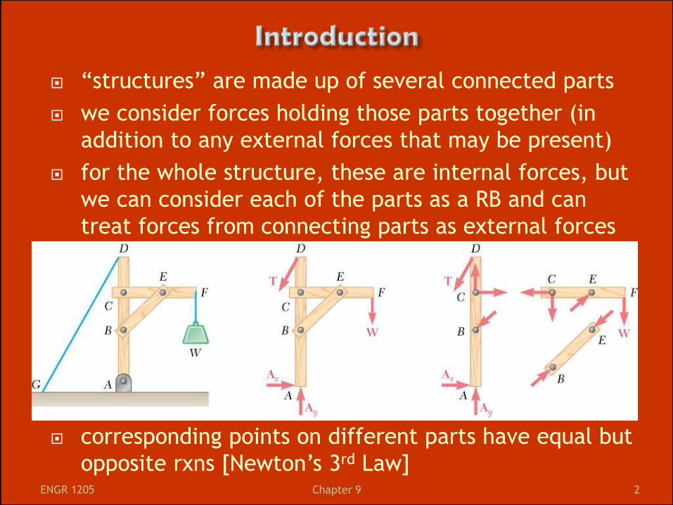
“structures” are made up of several connected parts
we consider forces holding those parts together (in
addition to any external forces that may be present)
for the whole structure, these are internal forces, but
we can consider each of the parts as a RB and can
treat forces from connecting parts as external forces
corresponding points on different parts have equal but
opposite rxns [Newton’s 3rd Law]
ENGR 1205 2 Chapter 9
in this chapter, we will look at:
Frames: they support loads, are usually
static and completely constrained, but they
have at least one multi-force member (as in
Figure on prior slide)
Machines: they transmit and modify forces -
they have moving parts and at least one
multi-force member
Trusses: they support loads, are static and
fully constrained, and are made of straight
members connected at joints - all parts are
“2 force elements”
ENGR 1205 3 Chapter 9
For all types of structures:
If the whole structure is in equilibrium then
any part of the structure must also be in
equilibrium
Can separate a structure into individual parts
(all in equilibrium)
Can “cut” a structure and examine a piece of
it (also in equilibrium)
ENGR 1205 4 Chapter 9
A system designed to support loads (forces and
moments)
Made up of multiple members
At least one member is acted upon by 3+ forces
(not two-force elements)
Can be internally stable or internally unstable
Stable – no matter what the external support
reactions are the frame maintains its shape
Unstable – if external support reactions are
removed the members of the frame move
relative to each other.
ENGR 1205 5 Chapter 9
frames are inter-connected rigid bodies
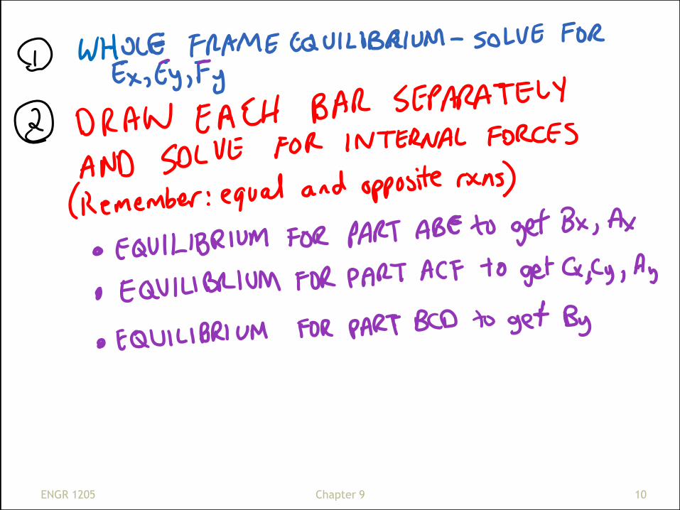
start by analyzing the whole system to get the
reactions at the supports (if possible – frames may
be statically indeterminate)
then isolate members or parts, for each one
separately draw a FBD and apply equations of
equilibrium
Total number of unknown force components must
be less than or equal to the number of
independent equations (3 per piece – the 3
equations for the whole frame are NOT
independent of the 3 equations for each piece)
ENGR 1205 6 Chapter 9
In general:
start with two force element and show their
member forces
guess at force senses, verify later by
looking at signs
then look at multi-force members
remember that Fx and Fy forces are same
magnitude but opposite sense on each side
of a connection
Write equilibrium equations for multi-force
member FBDs and back-substitute answers
to solve all of your FBDs ENGR 1205 7 Chapter 9
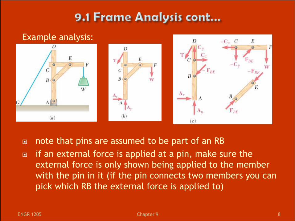
Example analysis:
note that pins are assumed to be part of an RB
if an external force is applied at a pin, make sure the
external force is only shown being applied to the member
with the pin in it (if the pin connects two members you can
pick which RB the external force is applied to)
ENGR 1205 8 Chapter 9
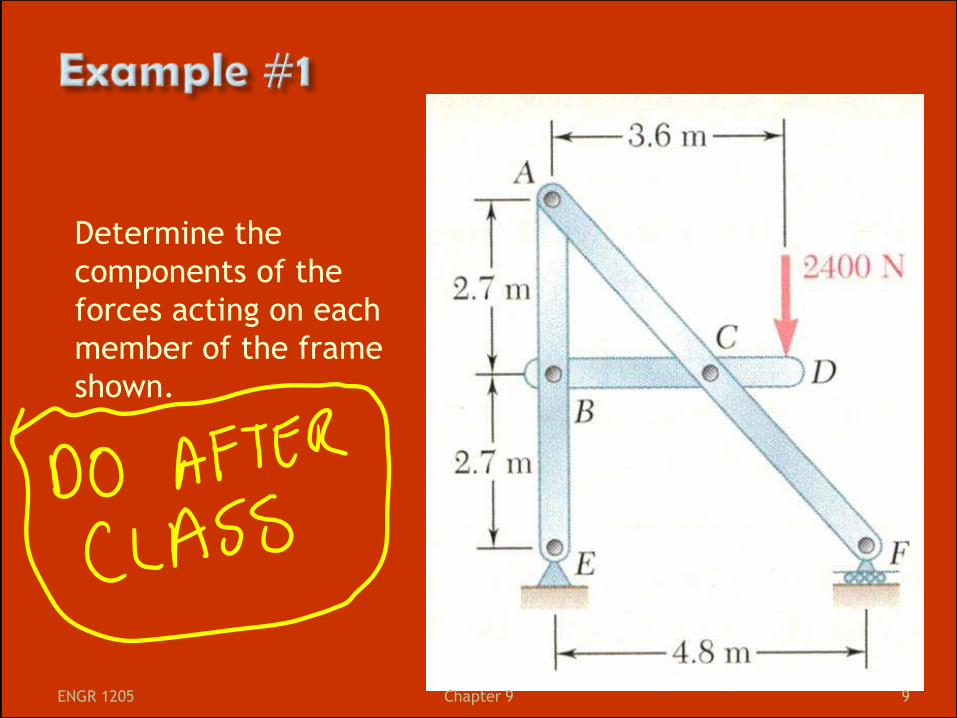
Determine the
components of the
forces acting on each
member of the frame
shown.
ENGR 1205 9 Chapter 9
ENGR 1205 10 Chapter 9

ENGR 1205 11 Chapter 9
Like frames (support loads, made of up multiple
members – at least one supports 3+ loads)
BUT, primary purpose is to transmit and modify
forces
they transform input forces (I/P) into output
forces (O/P)
Generally we want to find the magnitude of the
O/P knowing the I/P … or vice versa (ratio of
output:input is “mechanical advantage”)
Often, machines won’t be fully constrained
because they’re designed to move – but they are
in equilibrium (assume they are at rest)
ENGR 1205 12 Chapter 9
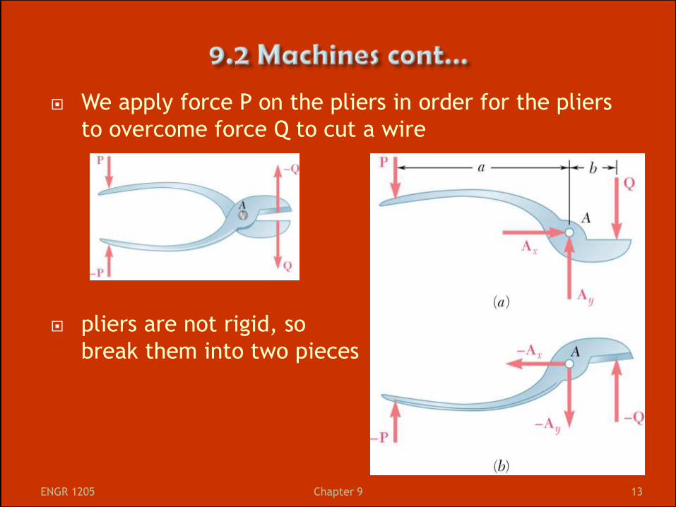
We apply force P on the pliers in order for the pliers
to overcome force Q to cut a wire
pliers are not rigid, so
break them into two pieces
ENGR 1205 13 Chapter 9
Use the same method as for frames
Draw FBD for each member
Put opposite forces at connections
Include input forces (act on the machine)
and the REACTIONS TO the output forces
(output forces act on something else – show
what the “something else” does to the
machine)
Often there are no external support reactions
ENGR 1205 14 Chapter 9

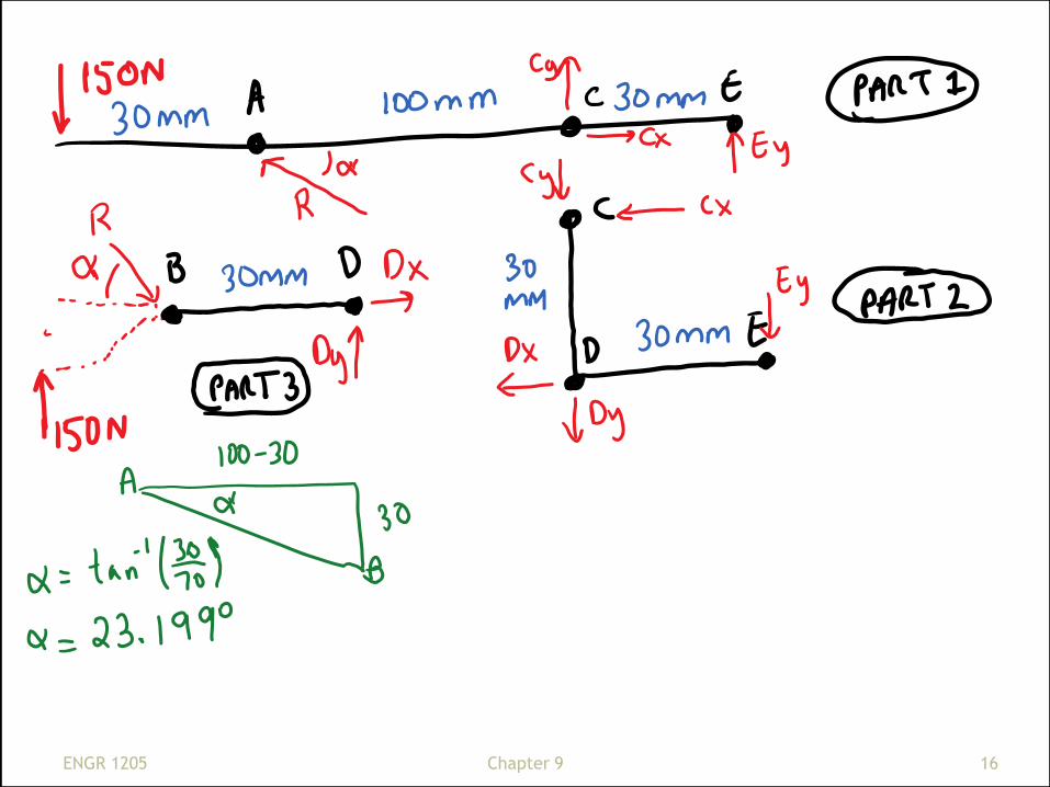
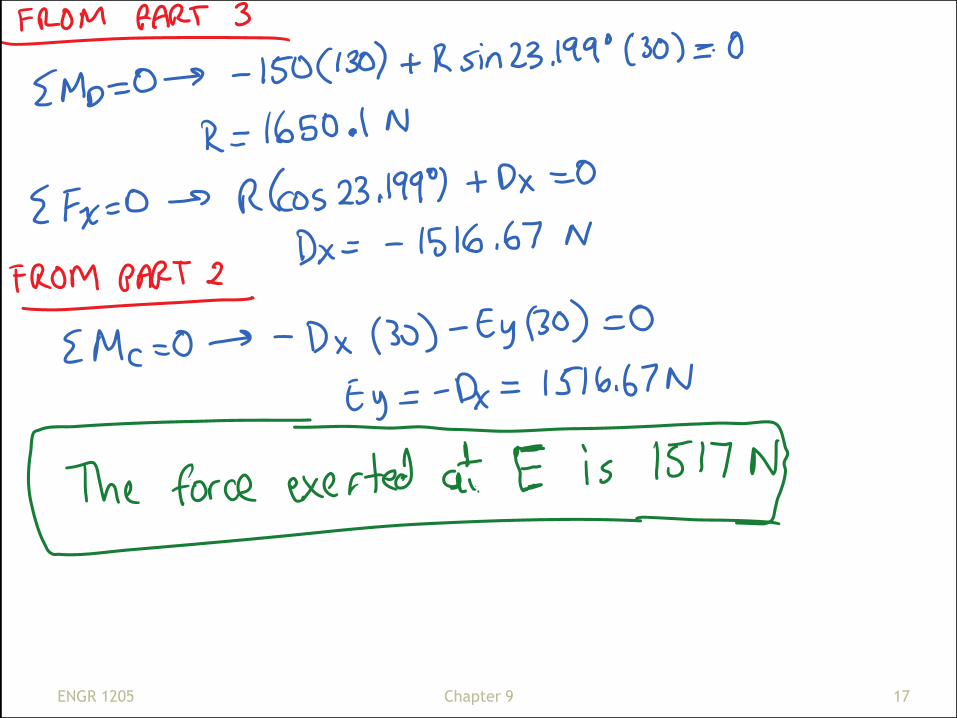
What forces are exerted on the bolt at E as a result of
the 150 N forces on the pliers?
ENGR 1205 15 Chapter 9
ENGR 1205 16 Chapter 9
ENGR 1205 17 Chapter 9
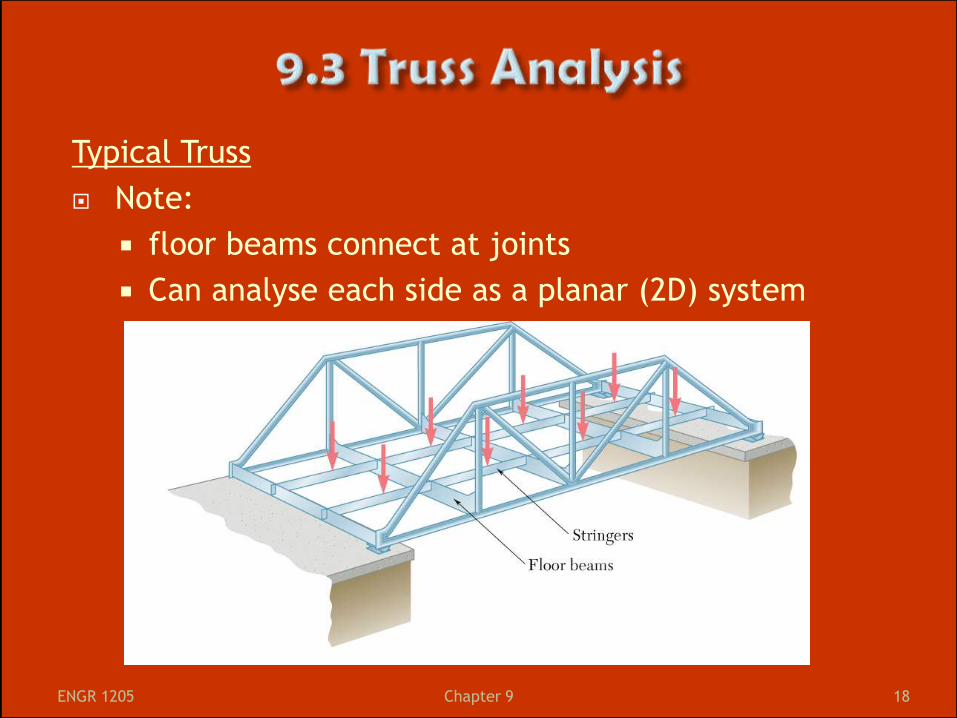
Typical Truss
Note:
floor beams connect at joints
Can analyse each side as a planar (2D) system
ENGR 1205 18 Chapter 9
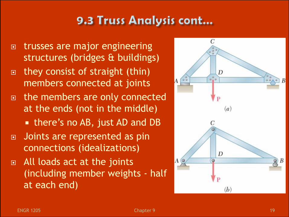
trusses are major engineering
structures (bridges & buildings)
they consist of straight (thin)
members connected at joints
the members are only connected
at the ends (not in the middle)
there’s no AB, just AD and DB
Joints are represented as pin
connections (idealizations)
All loads act at the joints
(including member weights - half
at each end)
ENGR 1205 19 Chapter 9
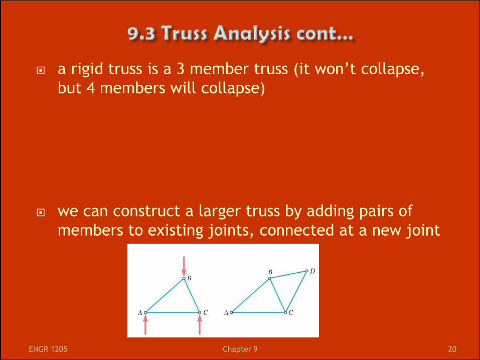
a rigid truss is a 3 member truss (it won’t collapse,
but 4 members will collapse)
we can construct a larger truss by adding pairs of
members to existing joints, connected at a new joint
ENGR 1205 20 Chapter 9
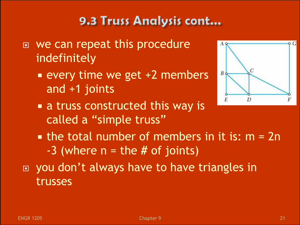
we can repeat this procedure
indefinitely
every time we get +2 members
and +1 joints
a truss constructed this way is
called a “simple truss”
the total number of members in it is: m = 2n
-3 (where n = the # of joints)
you don’t always have to have triangles in
trusses
ENGR 1205 21 Chapter 9
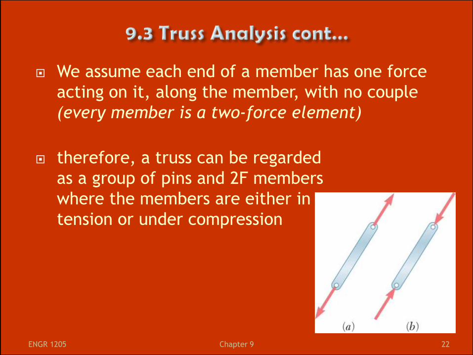
We assume each end of a member has one force
acting on it, along the member, with no couple
(every member is a two-force element)
therefore, a truss can be regarded
as a group of pins and 2F members
where the members are either in
tension or under compression
ENGR 1205 22 Chapter 9
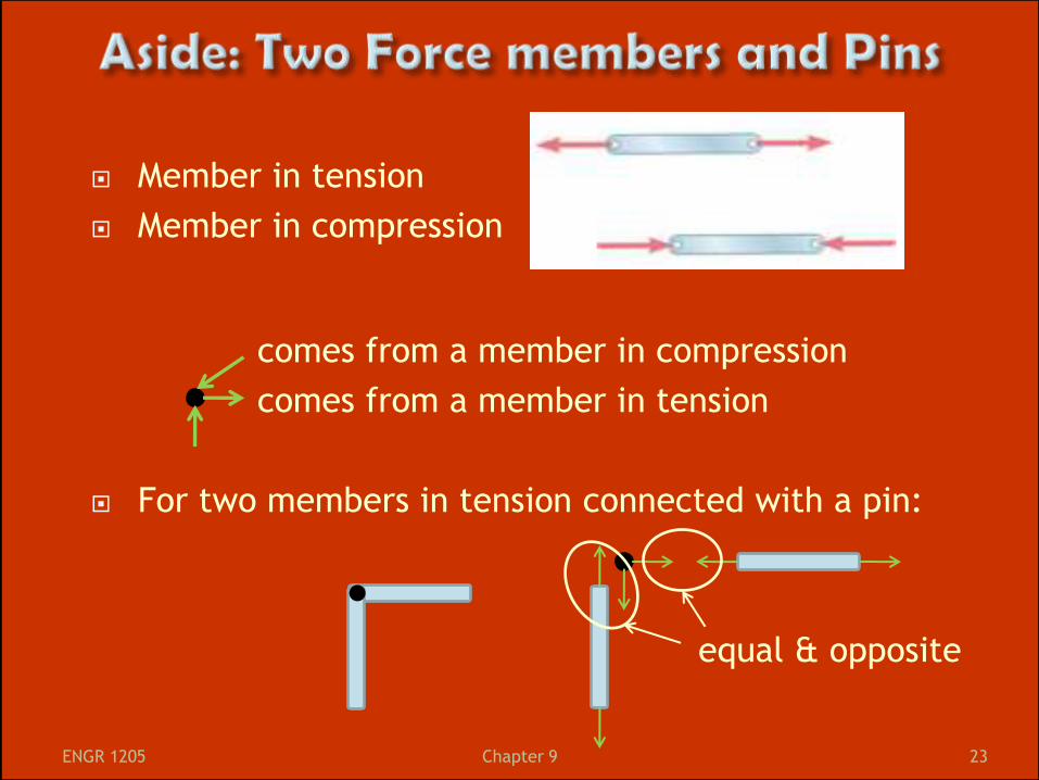
Member in tension
Member in compression
comes from a member in compression
comes from a member in tension
For two members in tension connected with a pin:
equal & opposite
ENGR 1205 23 Chapter 9
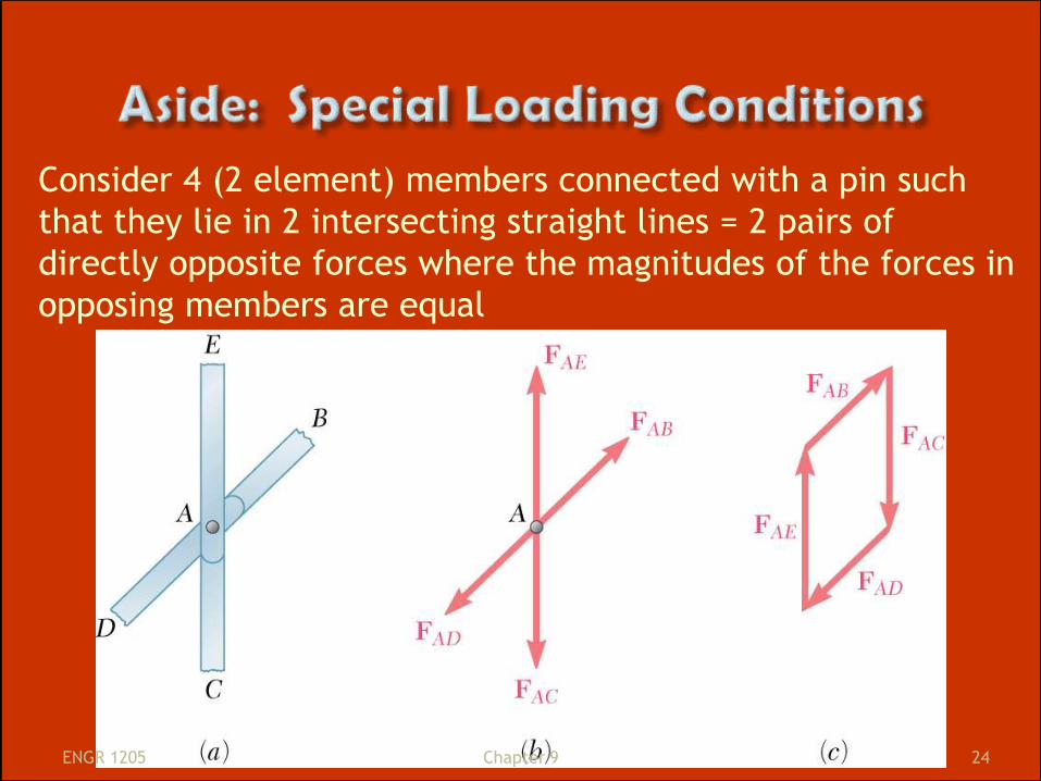
Consider 4 (2 element) members connected with a pin such
that they lie in 2 intersecting straight lines = 2 pairs of
directly opposite forces where the magnitudes of the forces in
opposing members are equal
ENGR 1205 24 Chapter 9
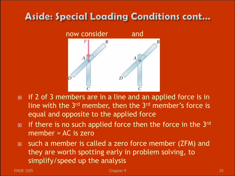
now consider and
if 2 of 3 members are in a line and an applied force is in
line with the 3rd member, then the 3rd member’s force is
equal and opposite to the applied force
if there is no such applied force then the force in the 3rd
member = AC is zero
such a member is called a zero force member (ZFM) and
they are worth spotting early in problem solving, to
simplify/speed up the analysis
ENGR 1205 25 Chapter 9
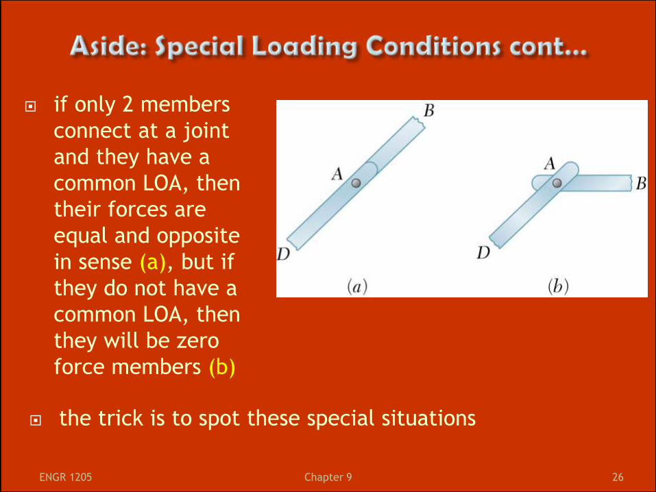
if only 2 members
connect at a joint
and they have a
common LOA, then
their forces are
equal and opposite
in sense (a), but if
they do not have a
common LOA, then
they will be zero
force members (b)
ENGR 1205 26 Chapter 9
the trick is to spot these special situations
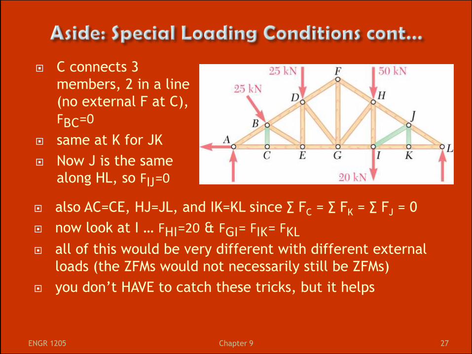
C connects 3
members, 2 in a line
(no external F at C),
FBC=0
same at K for JK
Now J is the same
along HL, so FIJ=0
ENGR 1205 27 Chapter 9
also AC=CE, HJ=JL, and IK=KL since ∑ FC = ∑ FK = ∑ FJ = 0
now look at I … FHI=20 & FGI= FIK= FKL
all of this would be very different with different external
loads (the ZFMs would not necessarily still be ZFMs)
you don’t HAVE to catch these tricks, but it helps
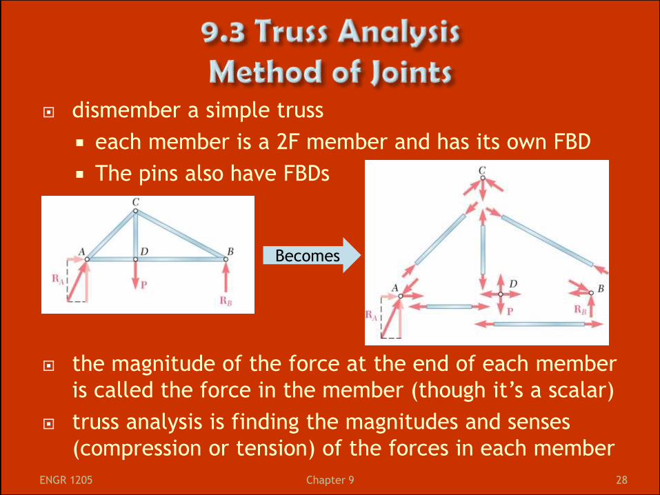
dismember a simple truss
each member is a 2F member and has its own FBD
The pins also have FBDs
the magnitude of the force at the end of each member
is called the force in the member (though it’s a scalar)
truss analysis is finding the magnitudes and senses
(compression or tension) of the forces in each member
Becomes
ENGR 1205 28 Chapter 9
since the truss is an RB in equilibrium, so
each pin (is a particle) has 2 equilibrium equations:
Σ𝐹𝑥 = 0 and Σ𝐹𝑦 = 0
if a truss has n pins, we have 2n equations to solve for
up to 2n unknowns
for a simple truss, m = 2n-3, so 2n = m+3
we can find the forces of all members + 3 rxns (e.g.
RAx, RAy, RBy) using pins as FBDs
the 3 equations we could use for the truss as a whole
are not independent of these pin equations, but you
can use them to find the rxns at the supports
ENGR 1205 29 Chapter 9
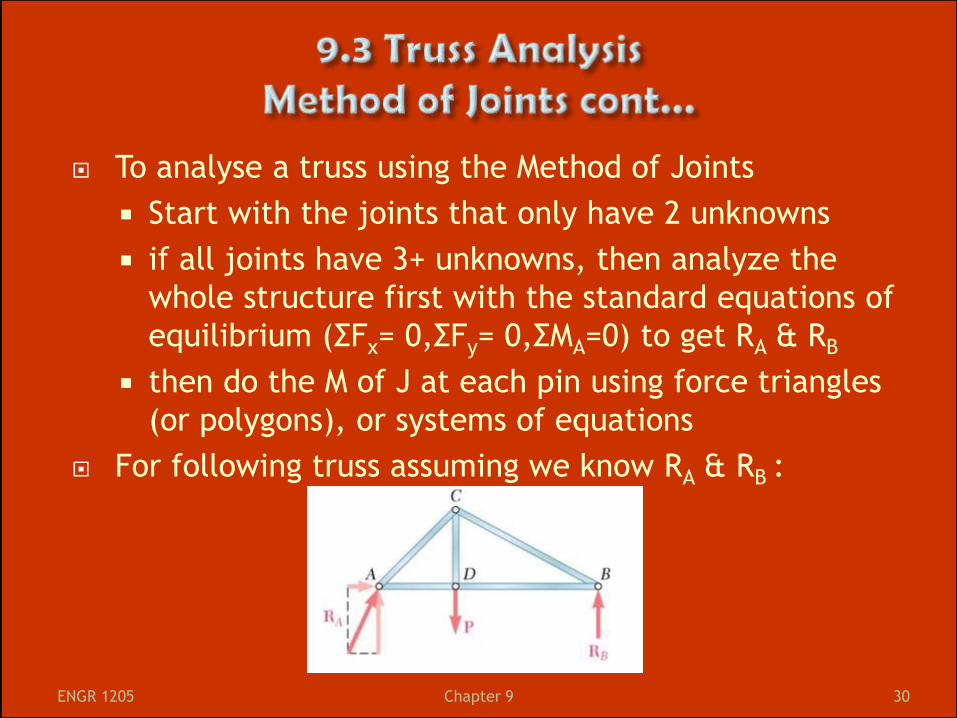
To analyse a truss using the Method of Joints
Start with the joints that only have 2 unknowns
if all joints have 3+ unknowns, then analyze the
whole structure first with the standard equations of
equilibrium (ΣFx= 0,ΣFy= 0,ΣMA=0) to get RA & RB
then do the M of J at each pin using force triangles
(or polygons), or systems of equations
For following truss assuming we know RA & RB :
ENGR 1205 30 Chapter 9
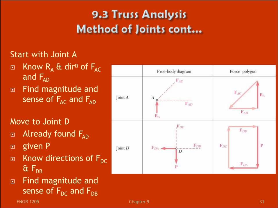
Start with Joint A
Know RA & dirn of FAC
and FAD
Find magnitude and
sense of FAC and FAD
Move to Joint D
Already found FAD
given P
Know directions of FDC
& FDB
Find magnitude and
sense of FDC and FDB
ENGR 1205 31 Chapter 9
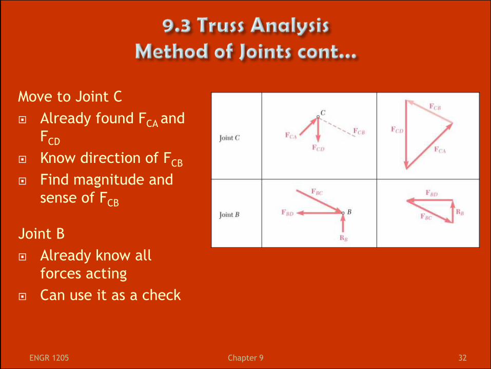
Move to Joint C
Already found FCA and
FCD
Know direction of FCB
Find magnitude and
sense of FCB
Joint B
Already know all
forces acting
Can use it as a check
ENGR 1205 32 Chapter 9
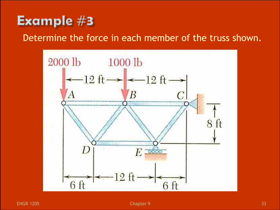
Determine the force in each member of the truss shown.
ENGR 1205 33 Chapter 9

ENGR 1205 34 Chapter 9
MofS is more efficient if you don’t need to solve for
all of the internal forces, you may only be asked for
forces for one or a few members
MofS is based on the idea that if the whole truss is in
static equilibrium then any section of the truss must
also be in equilibrium
Method:
“Cut” the truss through the members that you are
interested in solving for
Draw the FBD for the section you are left with
Ideally you have 3 unknowns (and 3 equations)
You may have to repeat the process
ENGR 1205 35 Chapter 9
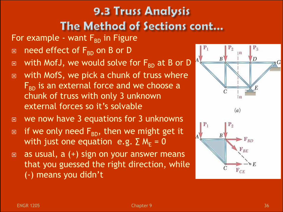
For example - want FBD in Figure
need effect of FBD on B or D
with MofJ, we would solve for FBD at B or D
with MofS, we pick a chunk of truss where
FBD is an external force and we choose a
chunk of truss with only 3 unknown
external forces so it’s solvable
we now have 3 equations for 3 unknowns
if we only need FBD, then we might get it
with just one equation e.g. ∑ ME = 0
as usual, a (+) sign on your answer means
that you guessed the right direction, while
(-) means you didn’t
ENGR 1205 36 Chapter 9
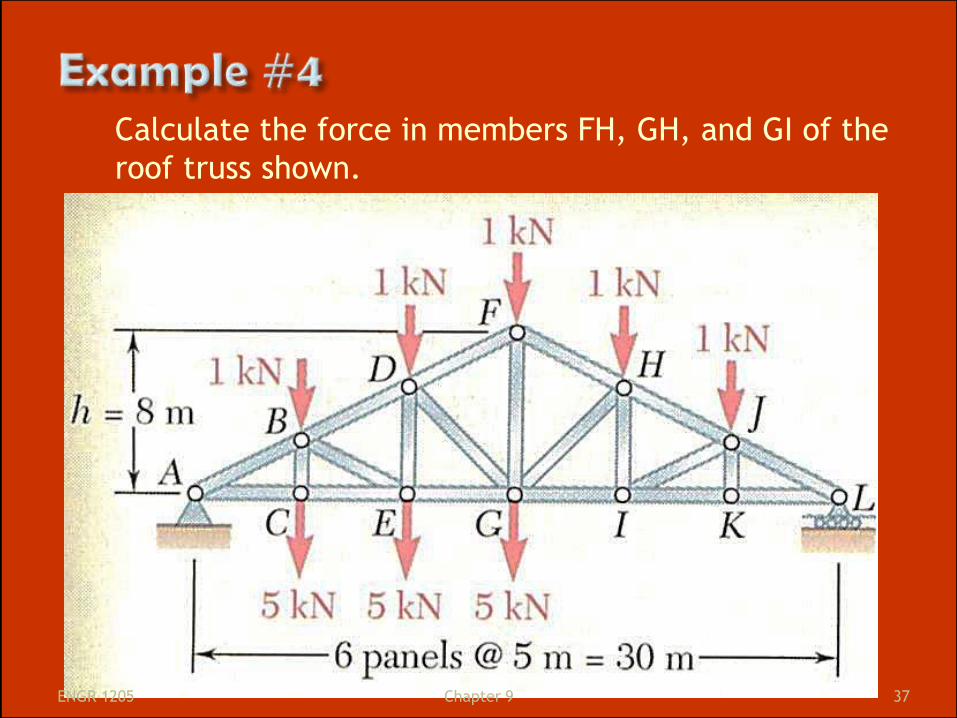
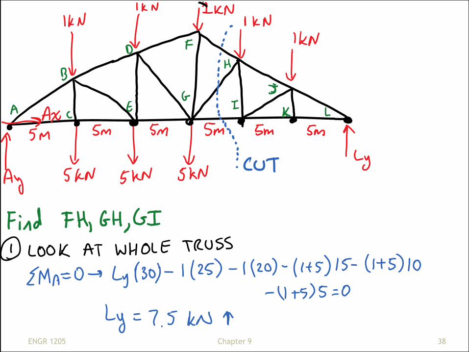
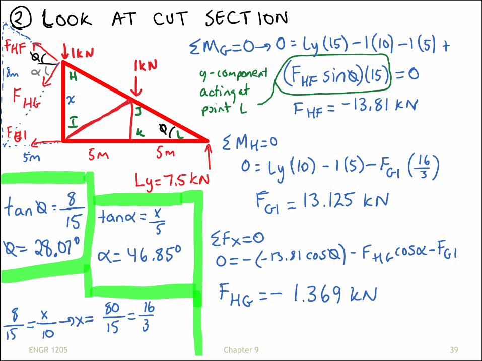
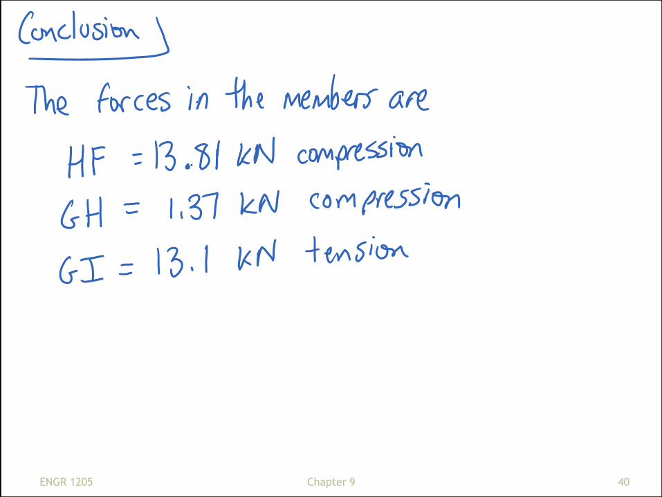
Calculate the force in members FH, GH, and GI of the
roof truss shown.
ENGR 1205 37 Chapter 9
ENGR 1205 38 Chapter 9
ENGR 1205 39 Chapter 9
ENGR 1205 40 Chapter 9
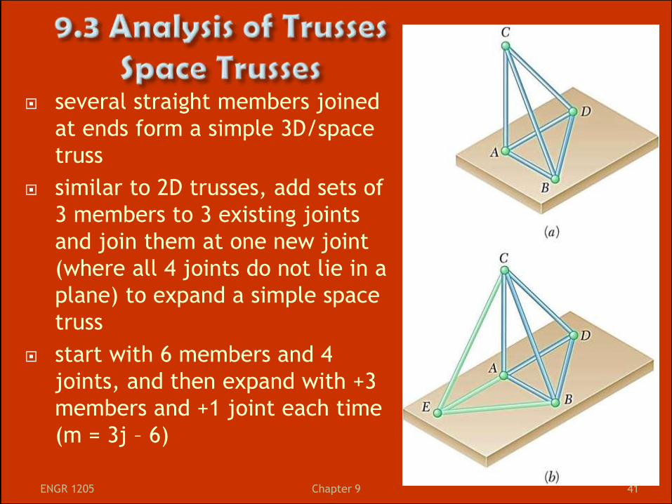
several straight members joined
at ends form a simple 3D/space
truss
similar to 2D trusses, add sets of
3 members to 3 existing joints
and join them at one new joint
(where all 4 joints do not lie in a
plane) to expand a simple space
truss
start with 6 members and 4
joints, and then expand with +3
members and +1 joint each time
(m = 3j – 6)
ENGR 1205 41 Chapter 9
for a space truss to be statically determinate and
completely constrained, use balls, rollers and ball and
socket joints to get 6 unknown rxns
(then use 6 equations of equilibrium for 3D)
for analyses, assume you have ball & socket joints
although they are often welds
therefore, each member is a 2F member and at each
joint you’ll have
∑ Fx = 0, ∑ Fy = 0, ∑ Fz = 0
in a truss with j joints, you get 3j equations and with
m = 3j-6 you get 3j = m + 6 (can solve for all the Fs in
the members + 6 rxns at supports)
start solving joints with ≤ 3 unknowns
ENGR 1205 42 Chapter 9
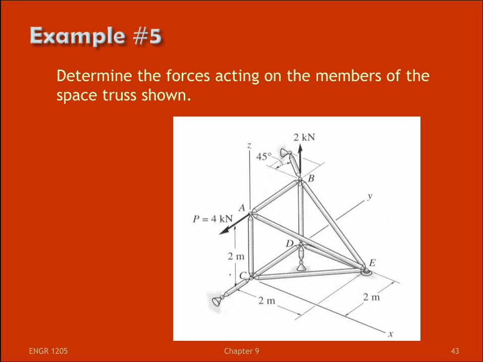
Determine the forces acting on the members of the
space truss shown.
ENGR 1205 43 Chapter 9

ENGR 1205 44 Chapter 9

ENGR 1205 45 Chapter 9

ENGR 1205 46 Chapter 9
simple trusses simply supported (1 pin and 1 roller) are
completely constrained and determinate trusses
for any other truss, if m = the # of members, j = the # of
joints, r = the # of rxns at supports, then we have 2j
independent equations of equilibrium
if (m+r) < 2j → we have fewer unknowns than equations and the
system is partially constrained (internally unstable)
if (m+r) > 2j → we have more unknowns than equations and the
system is statically determinate (redundancies exists)
if (m+r) = 2j → we have the same # of unknowns as equations
BUT it may not be determinate since some equations may
not be able to be satisfied
ONLY if all rxns and forces in members can be determined
will it be completely constrained and determinate
(otherwise it is improperly constrained)
ENGR 1205 47 Chapter 9