Embed Size (px)
Citation preview

1©2008 The Tokyo Electric Power Company, Inc. All Rights Reserved.
Outline of PostOutline of Post--Seismic InvestigationsSeismic Investigationsand Evaluation Plan forand Evaluation Plan for
KashiwazakiKashiwazaki--KariwaKariwa Nuclear Power Nuclear Power Station Unit 7Station Unit 7
January 2008
The Tokyo Electric Power Co., Inc.

2
OutlineOutline
Overview of Post-Seismic Investigations and Evaluations
Inspections of Systems, Structures and Components
Seismic Response Analyses
©2008 The Tokyo Electric Power Company, Inc. All Rights Reserved.

3
PostPost--Seismic Investigations and Evaluation PlanSeismic Investigations and Evaluation Plan• TEPCO has been conducting Post-Seismic Investigation and
Evaluation in accordance with the internal manuals.
• TEPCO has submitted the plan for mechanical, electrical and I&C components of Unit 7 to the extent instructed by NISA*.– *Instruction by NISA: “Plan to inspect and evaluate the soundness of
facilities at the Kashiwazaki-Kariwa Nuclear Power Station following the 2007 Niigataken Chuetsu-oki Earthquake” (issued on 11/9/07 )
• Current Inspections and Analyses that are now being taken place at Unit 7 are based on the Plan.
• Plans for other Units and/or Facilities are to be submitted.

4
Overview of Comprehensive Overview of Comprehensive PostPost--SeimicSeimicEvaluation Evaluation
【Seismic Response Analyses】
Seismic responseanalysis result
【Inspections of SSCs】
Basic inspection
Additionalinspection
【Comprehensive evaluation of equipment integrity】
Good
RelativelyLess margin
No detectionof abnormality
Abnormal
©2008 The Tokyo Electric Power Company, Inc. All Rights Reserved.
5
Inspections of Systems, Inspections of Systems, Structures and ComponentsStructures and Components
©2008 The Tokyo Electric Power Company, Inc. All Rights Reserved.

6
Analyze by the conditions at the earthquake hit and by following the same procedures as the ones on the construction permit.
Inspections for Seismic Classes A/AsInspections for Seismic Classes A/As
Term: August 2 to September 7, 2007Inspectors: 50 Manufactures’ Engineers and 10 TEPCO Engineers
(Completed)
Result: No significant abnormalities to possibly influence on Seismic Safety were identified.
Analyses
Inspection in detail by Seismic Structure Inspections ( Support, Foundation etc.), Functional Test and so on
BasicInspection
GeneralVisual
Inspection
Visual Inspections were taken place by seismic design specialists and confirmed no significant to maintain current cold shutdown.
Abnormality possibly to influence to major components
IdentifiedAbnormality
Point that the result of analysis is severe
Examples:Dimension MeasurementNon-destructive Test- Foundation Bolts,
PipingsDestructive Test using the
actual components- PLR Pipings etc.Shaking Test by Mockups- Viewpoint of Public
Acceptance should be taken in account
Based on the each inspection result, Cause Analysis is taken place by the detailed inspections.
AdditionalInspections
Evaluate the Soundness by the combination of these itemsComprehensiveEvaluation
Ex.) Insulation Fall
Completion Goal for Unit 7: June, 2008

7
Analyze some components that might cause repercussions for more significant components
(Completed)
Analyses(Partially)
Investigate in detail by Seismic Structure Inspections ( Support, Foundation etc.), Functional Test and so on
BasicInspections
WalkdownConfirmed the Post-Seismic Condition of Components and nonconformities by Engineers from TEPCO and its Partners.
IdentifiedAbnormality
Point that the result of analysis is severe
AdditionalInspections
Evaluate the Soundness by the combination of these itemsComprehensiveEvaluation
Examples of Abnormalities:B Class: Reactor Building Ceiling CraneC Class: Transformers, Fire Protection Piping,
Filtered Water Tank, etc.
Completion Goal for Unit 7: June, 2008
Inspections for Seismic Classes B/CInspections for Seismic Classes B/C
Examples:Dimension MeasurementNon-destructive TestDestructive Test using the
actual componentsShaking Test by Mockups
Based on the each inspection result, Cause Analysis is taken place by the detailed inspections.

8
Component Categories for Unit 7Component Categories for Unit 7
Dynamic Components Static Components
1) Vertical Pump2) Horizontal Pump3) Reciprocating Pump4) Turbine for Pump Drive5) Motor6) Fan7) Refrigerating Machine8) Air compressor9) Valve10)Damper11)Emergency Diesel Generator12)Control Rod13)Control Rod Drive14)Main Turbine15)Generator16)Internal Pump17)Fuel Handling Machine18)Crane
19)Reactor Pressure Vessel20)Reactor Internals21)Piping22)Fuel Rack23)Heat Exchanger24)Condenser, Feed Water Heater,
Moisture Separator & Reheater25)Pool Liner26)Transformer27)Battery28)Breaker29)Gauge, Relay,, Regulator, Detector,
Transducer30)Primary Containment Vessel31)Accumulator32)Filtration Demineralizer33)Strainer / Filter34)Steam Jet Air Ejector
35)Dehumidifier36)Tank37)Instrumental Rack38)Control Panel39)HVAC Duct40)Fuel Assembly
●Buildings and structures such as reactor building etc. are also checked and evaluated to their structural characteristics.
©2008 The Tokyo Electric Power Company, Inc. All Rights Reserved.

9
Inspections Inspections –– Dynamic ComponentsDynamic Components
SSC Basic inspectionResults of
Inspection &analysisAdditionalinspection
Dynam
ic Com
ponent
Disassemblyinspection
Visual inspection
Test run
Result
Judgment ofadditionalinspection
Result of seismic responseanalysis
・ vertical-type pump
・ horizontal-type pump
・ reciprocating pump
・ motors
・ fans
・ refrigerating machine
・ Control rod drive
・ main turbine
・ internal pump etc.
Performance
Vibration
Leakage
©2008 The Tokyo Electric Power Company, Inc. All Rights Reserved.

10
Inspections Inspections –– Static ComponentsStatic Components
SSC Basic inspectionResults of
Inspection &analysisAdditionalinspection
Static C
omponent
Detailed visual inspection
Confirmation of dimension
Nondestructive testing
Disassembly inspection
Pressure test
Material test
Visual inspection
Design evaluation
Result
Judgment ofadditionalinspection
Result of seismic responseanalysis
Visual inspection
Leak test
・ piping
・ heat exchanger
・ pool lining
・ tank etc.
・ reactor pressure vessel
etc.Selection of inspection point
©2008 The Tokyo Electric Power Company, Inc. All Rights Reserved.

11
Inspections Inspections –– Static Components (continued)Static Components (continued)
SSC Basic inspectionResults of
Inspection &analysisAdditionalinspection
Static C
omponent
Disassembly inspection
Characteristic test
Confirmation of dimension
Visual inspection
Function checkout test
Result
Judgment ofadditionalinspection
Result of seismic responseanalysis
Visual inspection・ control panel
・ instrumentation rack
etc.
・ trans former
・ control system
equipment
etc.
Insulation resistancemeasurement
Result
Judgment ofadditionalinspection
©2008 The Tokyo Electric Power Company, Inc. All Rights Reserved.

12
Inspections Inspections –– Support StructuresSupport Structures
SSC Basic inspectionResults of
Inspection &analysisAdditionalinspection
Support S
tructure
Percussion test
Nondestructive testing
Material test
Design evaluation
・ Basement of
equipmentSelection of inspection point Confirmation of loosed bolt
Surface inspection
Visual inspection Result
Judgment ofadditionalinspection
Result of seismic responseanalysis
Surface inspection
Nondestructive testing
Visual inspection Result
Judgment ofadditionalinspection
Result of seismic responseanalysis
・ Supporting leg
©2008 The Tokyo Electric Power Company, Inc. All Rights Reserved.

13
Inspections Inspections –– Support Structures (continued)Support Structures (continued)
SSC Basic inspectionResults of
Inspection &analysisAdditionalinspection
Support S
tructure
Material test
・ Static restraint
Surface inspection
Nondestructive testing
Visual inspection Result
Judgment ofadditionalinspection
Result of seismic responseanalysis
Shake down
Disassembly inspection
Visual inspection Result
Judgment ofadditionalinspection
Result of seismic responseanalysis
・ Dynamic restraint
©2008 The Tokyo Electric Power Company, Inc. All Rights Reserved.

14
Seismic Response AnalysesSeismic Response Analyses
©2008 The Tokyo Electric Power Company, Inc. All Rights Reserved.

15
Overall FlowOverall Flow
Middle floor data from the earthquake
ComparisonSeismic response analysis of the building FRS Other
equipmentLarge-sized components
Building –component
coupled analysis
Detailed analysis Calculating equipment response
Integrity evaluation (comparison with allowable stress)
Comprehensive Evaluations of Equipment Integrity
Equipment of Class A and As
Data from this earthquake
Evaluation of the Building
Response > allowable stress
©2008 The Tokyo Electric Power Company, Inc. All Rights Reserved.

16
Seismic Response AnalysisSeismic Response Analysisof Reactor Buildingof Reactor Building
©2008 The Tokyo Electric Power Company, Inc. All Rights Reserved.

17
Components to be Seismically AnalyzedComponents to be Seismically AnalyzedComponents that are classified as Classes 1, and 2 with immense seismic significance (Seismic classes As and Acomponents and the other components subject to seismic analysis with dynamic ground motion)
©2008 The Tokyo Electric Power Company, Inc. All Rights Reserved.

18
Analysis Overview of Reactor BuildingsAnalysis Overview of Reactor Buildings
Transfer function from the top of the foundation slab to each part of the building
(ω)HBR&&
(t)uB&&
Time history waveform of the seismic wave observed on the top of the foundation slab
(t)uF&&
(Time domain)
Time history waveform of the response of each part of the building
Fourier transformation of theresponse of
each part of the building
Time history waveform of the seismic wave observed on the top of the foundation slab
Fourier transformation of the seismic wave observed on the top of the foundation slab
(Frequency domain)
(ω)UF&&
(ω)UB&&
(ω)H(ω)*U(ω)U BRBF&&&&&& =
0
π
−π
(t)uB&&
Multiplication of transfer function
Am
plitude
Phase
Frequency Frequency0
0
π
π
Fourier inversetransformation
Fourier transformation
0
π
−π
Am
plitude
Phase
Frequency Frequency0
0
π
π
Unit 1 Reactor Building
88m
45m
©2008 The Tokyo Electric Power Company, Inc. All Rights Reserved.
19
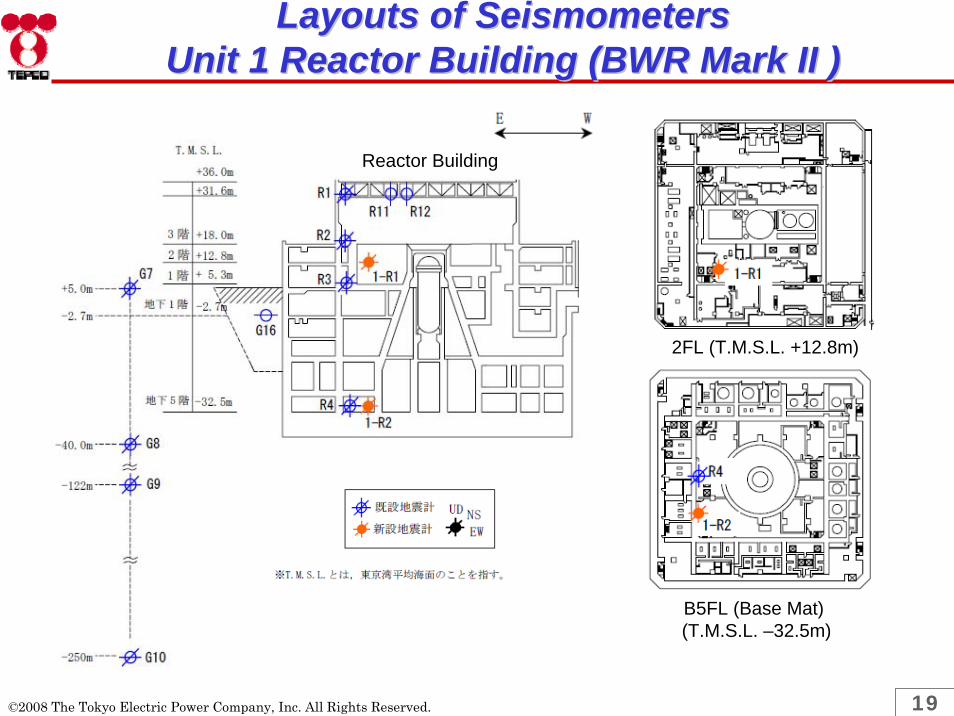
Layouts of SeismometersLayouts of SeismometersUnit 1 Reactor Building (BWR Mark II )Unit 1 Reactor Building (BWR Mark II )
©2008 The Tokyo Electric Power Company, Inc. All Rights Reserved.
B5FL (Base Mat)(T.M.S.L. –32.5m)
2FL (T.M.S.L. +12.8m)
Reactor Building

20
Layouts of Seismometers in Unit 7 R/BLayouts of Seismometers in Unit 7 R/B
©2008 The Tokyo Electric Power Company, Inc. All Rights Reserved.
Reactor Building
3FL (T.M.S.L. +23.5m)
B3FL (Base Mat)(T.M.S.L. –8.2m)
21
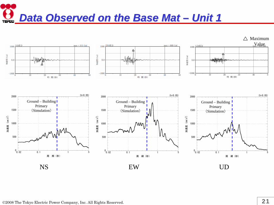
Data Observed on the Base Mat Data Observed on the Base Mat –– Unit 1Unit 1
NS EW UD
Maximum Value
0.1 10
500
1000
1500
2000
周 期(秒)
加速度 (cm/s2)
(h=0.05)
0.02 5 0.1 10
500
1000
1500
2000
周 期(秒)
加速度 (cm/s2)
(h=0.05)
0.02 5 0.1 10
500
1000
1500
2000
周 期(秒)
加速度 (cm/s2)
(h=0.05)
0.02 5
Ground – Building Primary
(Simulation)
Ground – Building Primary
(Simulation)
Ground – Building Primary
(Simulation)
©2008 The Tokyo Electric Power Company, Inc. All Rights Reserved.

22
NS EW UD
0.1 10
500
1000
1500
2000
周 期(秒)
加速度 (cm/s2)
(h=0.05)
0.02 5 0.1 10
500
1000
1500
2000
周 期(秒)
加速度 (cm/s2)
(h=0.05)
0.02 5 0.1 10
500
1000
1500
2000
周 期(秒)
加速度 (cm/s2)
(h=0.05)
0.02 5
Ground – Building Primary
(Simulation)
Ground – Building Primary
(Simulation)
Ground – Building Primary
(Simulation)
Data Observed on the Base Mat Data Observed on the Base Mat –– Unit 7Unit 7Maximum
Value
©2008 The Tokyo Electric Power Company, Inc. All Rights Reserved.

23
Analysis Models Analysis Models –– Unit 1 Reactor BuildingUnit 1 Reactor Building
T.M.S.L. 36.0m
T.M.S.L. 24.5m
T.M.S.L. 18.0m
T.M.S.L. 12.8m
T.M.S.L. 5.3m
T.M.S.L. -2.7m
T.M.S.L. -9.7m
T.M.S.L. -16.1m
T.M.S.L. -25.1m
T.M.S.L. -32.5m
T.M.S.L. -40.0m
Horizontal Vertical
T.M.S.L. 5.0m(GL)
T.M.S.L. 5.0m(GL)
©2008 The Tokyo Electric Power Company, Inc. All Rights Reserved.

24
Horizontal Vertical
GLGL
T.M.S.L. 49.7m
T.M.S.L. 38.2m
T.M.S.L. 31.7m
T.M.S.L. 23.5m
T.M.S.L. 18.1m
T.M.S.L. 12.3m
T.M.S.L. 4.8m
T.M.S.L. -1.7m
T.M.S.L. -8.2m
T.M.S.L. -13.7m
T.M.S.L. 12.0m(GL)
T.M.S.L. 12.0m(GL)
Analysis Models Analysis Models –– Units 7 Reactor BuildingUnits 7 Reactor Building
©2008 The Tokyo Electric Power Company, Inc. All Rights Reserved.

25
NS EW
* 1999 – Allowable Stress Design Method – Standards for Calculating Reinforced Concrete Structures and the Description Thereof by the Architectural Institute of Japan
B5F
B4F
B3F
B2F
B1F
1F
2F
3F
Overhead Crane
Rooftop
0 0.1 0.2 0.3 0.4
最大応答せん断ひずみ(×10-3)
K1 R/BNS
ひび割れ発生の目安値
0 0.1 0.2 0.3 0.4
最大応答せん断ひずみ(×10-3)
K1 R/BEW
ひび割れ発生の目安値
B5F
B4F
B3F
B2F
B1F
1F
2F
3F
Overhead Crane
Rooftop
Approximate value at which shear cracks would occur*
Approximate value at which shear cracks would occur*
Results of AnalysisResults of AnalysisUnit 1 Maximum Response Shear StrainUnit 1 Maximum Response Shear Strain
©2008 The Tokyo Electric Power Company, Inc. All Rights Reserved.
Max. Response Shear StrainMax. Response Shear Strain

26
NS EW
0 0.1 0.2 0.3 0.4-8.2
最大応答せん断ひずみ(×10-3)
T.M
.S.L. (m)
K7 R/BNS方向
ひび割れ発生の目安値
NS 外壁NS RCCV
0 0.1 0.2 0.3 0.4-8.2
最大応答せん断ひずみ(×10-3)
T.M
.S.L. (m)
K7 R/BEW方向
ひび割れ発生の目安値
EW 外壁EW RCCV
* 1999 – Allowable Stress Design Method – Standards for Calculating Reinforced Concrete Structures and the Description Thereof by the Architectural Institute of Japan
Approximate value at which shear cracks would occur*
Approximate value at which shear cracks would occur*
B4F
B3F
B2F
B1F
1F
2F
3F
4F
Crane floor
Rooftop
B4F
B3F
B2F
B1F
1F
2F
3F
4F
Crane floor
Rooftop
B4F
B3F
B2F
B1F
1F
2F
3F
4F
Overhead Crane
Rooftop
B4F
B3F
B2F
B1F
1F
2F
3F
4F
Overhead Crane
Rooftop
Results of AnalysisResults of AnalysisUnit 7 Maximum Response Shear StrainUnit 7 Maximum Response Shear Strain
©2008 The Tokyo Electric Power Company, Inc. All Rights Reserved.
Max. Response Shear Strain Max. Response Shear Strain
Exterior Wall Exterior Wall

27
Unit 7
Observed
Analyzed
Observed
Analyzed
Observed
Analyzed
K7 R/B UD(TMSL23.5m)h=0.05
Cycle (second)
Acc
eler
atio
n re
spon
se sp
ectru
m(m
/s2 )K7 R/B NS
(TMSL23.5m)h=0.05
K7 R/B EW(TMSL23.5m)h=0.05
Acc
eler
atio
n re
spon
se sp
ectru
m(m
/s2 )
Acc
eler
atio
n re
spon
se sp
ectru
m(m
/s2 )
Cycle (second) Cycle (second)
0
10
20
30
40
0.02 0.1 1 5
0
10
20
30
40
0.02 0.1 1 5
0
10
20
30
40
0.02 0.1 1 5
Results of AnalysesResults of AnalysesFloor Response Spectra (intermediate floors)Floor Response Spectra (intermediate floors)
©2008 The Tokyo Electric Power Company, Inc. All Rights Reserved.
Unit 1
NS EW UD
0
10
20
30
40
0.1 1
観測
解析
加速
度応
答ス
ペク
トル(m/s2)
周期(秒)
K1 R/B NS(TMSL12.8m)h=0.05
0.02 50
10
20
30
40
0.1 1
観測
解析
加速度応答スペクトル(m/s2)
周期(秒)
K1 R/B EW(TMSL12.8m)h=0.05
0.02 50
10
20
30
40
0.1 1
観測
解析
加速
度応
答ス
ペク
トル(m/s2)
周期(秒)
K1 R/B UD(TMSL12.8m)h=0.05
Acc
eler
atio
n re
spon
se sp
ectru
m(m
/s2 )
Acc
eler
atio
n re
spon
se sp
ectru
m(m
/s2 )
Acc
eler
atio
n re
spon
se sp
ectru
m(m
/s2 )
Cycle (second)Cycle (second)Cycle (second)
Observed
Analyzed
Observed
Analyzed
Observed
Analyzed
Observed
Analyzed
Observed
Analyzed

28
Result of Unit 7 ComponentResult of Unit 7 ComponentResponse AnalysesResponse Analyses
©2008 The Tokyo Electric Power Company, Inc. All Rights Reserved.

29
Structural Strength of Representative Unit 7 EquipmentStructural Strength of Representative Unit 7 Equipment
Subject Natural period Stress
Calculated Stress(N/mm2)
Allowable(IIIAS)
(N/mm2)Analysis
[Note 1]
Reactor pressure vessel(Foundation bolt) 0.07 Tension 120 490 A
Core support structure(Shroud support) 0.14 Axial
compression 40 240 B
Residual heat removal piping 0.21 Primary 200 270 B
Residual heat removal pump(Foundation bolt)
0.05 or lower Shear 10 350 A
Main steam piping 0.17 Primary 140 280 B
Containment vessel(Dry well)
0.43(NS)0.42(EW)
Bending 30 260 A
Note1. A indicates “simple evaluation”, and B indicates “evaluation equivalent to that performed during design”
©2008 The Tokyo Electric Power Company, Inc. All Rights Reserved.
Beginning of life
Middle of Life
End of Life Analysis
0.21 0.22 BRatio to Allowable Stress 0.35Fuel Cladding Tube
(Supporting Grid Interval)

30
Dynamic Functionality of RepresentativeDynamic Functionality of RepresentativeUnit 7 EquipmentUnit 7 Equipment
Relative Displacement (mm)Subject Natural
period*1Calculated Value*2 Functionality-Confirmed
Relative Displacement*2
Control rod insertion performance 0.21 10 40
*1 The natural period is horizontal and rounded off to the third decimal place.*2 The first digit is rounded up in the calculated value. The first digit is disregarded for functionality-confirmed relative displacement.*3 G=9.8065(m/s2)*4 The second digit after the decimal point is rounded up in the calculated value.
Subject Natural period*1
Horizontal Acceleration (G) *3 Vertical Acceleration (G) *3
Calculated Value*4
Functionality-confirmed
acceleration
Calculated Value*4
Functionality-confirmed
acceleration
Residual heat removal system pump 0.05 or lower 0.4 10.0 0.4 1.0
©2008 The Tokyo Electric Power Company, Inc. All Rights Reserved.

31
Unit 7 R/B Floor Response Spectra (1/4)Unit 7 R/B Floor Response Spectra (1/4)(Horizontal) (Vertical)
Overhead Crane Level
4F
KK-7 R/B TMSL +38.2m(減衰1.0%)
0.0
2.0
4.0
6.0
8.0
10.0
0.01 0.10 1.00
周期(秒)
加速
度(
G)
建設時静的震度(上下)
建屋応答解析結果(上下)
KK-7 R/B TMSL +31.7m(減衰1.0%)
0.0
2.0
4.0
6.0
8.0
10.0
0.01 0.10 1.00
周期(秒)
加速
度(
G)
建設時静的震度(上下)
建屋応答解析結果(上下)
KK-7 R/B TMSL +38.2m (減衰1.0%)
0.0
2.0
4.0
6.0
8.0
10.0
0.01 0.10 1.00
周期(秒)
加速
度(
G)
建設時S2(NS,EW包絡)
建屋応答解析結果(NS,EW包絡)
KK-7 R/B TMSL +31.7m (減衰1.0%)
0.0
2.0
4.0
6.0
8.0
10.0
0.01 0.10 1.00周期(秒)
加速
度(
G)
建設時S2(NS,EW包絡)
建屋応答解析結果(NS,EW包絡)
©2008 The Tokyo Electric Power Company, Inc. All Rights Reserved.
Cycle (second)
Cycle (second)
Cycle (second)
Cycle (second)
Acce
lera
tion
(G)
Acce
lera
tion
(G)
Acce
lera
tion
(G)
Acce
lera
tion
(G)
Black: Static seismic coefficient of the design (UD)Red: Result of Building Response Analysis (UD)
Black: Static seismic coefficient of the design (UD)Red: Result of Building Response Analysis (UD)
Black: S2 of the design (NS-EW Inclusion)Red: Result of Building Response Analysis (NS-EW
Inclusion)
Black: S2 of the design (NS-EW Inclusion)Red: Result of Building Response Analysis (NS-EW
Inclusion)
(D.F. 1.0%) (D.F. 1.0%)
(D.F. 1.0%) (D.F. 1.0%)

32
KK-7 R/B TMSL +23.5m (減衰1.0%)
0.0
2.0
4.0
6.0
8.0
10.0
0.01 0.10 1.00
周期(秒)
加速
度(
G)
建設時S2(NS,EW包絡)
建屋応答解析結果(NS,EW包絡)
観測波(NS,EW包絡)
KK-7 R/B TMSL +23.5m(減衰1.0%)
0.0
2.0
4.0
6.0
8.0
10.0
0.01 0.10 1.00
周期(秒)
加速
度(
G)
建設時静的震度(上下)
建屋応答解析結果(上下)
観測波(上下)
Observed data Observed data
(Horizontal) (Vertical)
3F
2F
KK-7 R/B TMSL +18.1m(減衰1.0%)
0.0
2.0
4.0
6.0
8.0
10.0
0.01 0.10 1.00
周期(秒)
加速
度(
G)
建設時静的震度(上下)
建屋応答解析結果(上下)
KK-7 R/B TMSL +18.1m (減衰1.0%)
0.0
2.0
4.0
6.0
8.0
10.0
0.01 0.10 1.00
周期(秒)
加速
度(
G)
建設時S2(NS,EW包絡)
建屋応答解析結果(NS,EW包絡)
Unit 7 R/B Floor Response Spectrum (2/4)Unit 7 R/B Floor Response Spectrum (2/4)
©2008 The Tokyo Electric Power Company, Inc. All Rights Reserved.
Acce
lera
tion
(G)
Acce
lera
tion
(G)
Acce
lera
tion
(G)
Acce
lera
tion
(G)
Cycle (second)
Cycle (second)
Cycle (second)
Cycle (second)
Black: S2 of the design (NS-EW Inclusion)Red: Result of Building Response Analysis (NS-EW
Inclusion)Blue: Observed Response (NS-EW Inclusion)
Black: S2 of the design (NS-EW Inclusion)Red: Result of Building Response Analysis (NS-EW
Inclusion)
Black: Static seismic coefficient of the design (UD)Red: Result of Building Response Analysis (UD)
Black: Static seismic coefficient of the design (UD)Red: Result of Building Response Analysis (UD)Blue: Observed Response (UD)
(D.F. 1.0%)
(D.F. 1.0%) (D.F. 1.0%)
(D.F. 1.0%)

33
(Horizontal) (Vertical)
1F
B1F
KK-7 R/B TMSL +12.3m(減衰1.0%)
0.0
2.0
4.0
6.0
8.0
10.0
0.01 0.10 1.00
周期(秒)
加速
度(
G)
建設時静的震度(上下)
建屋応答解析結果(上下)
KK-7 R/B TMSL +4.8m(減衰1.0%)
0.0
2.0
4.0
6.0
8.0
10.0
0.01 0.10 1.00
周期(秒)
加速
度(
G)
建設時静的震度(上下)
建屋応答解析結果(上下)
KK-7 R/B TMSL +12.3m (減衰1.0%)
0.0
2.0
4.0
6.0
8.0
10.0
0.01 0.10 1.00
周期(秒)
加速
度(
G)
建設時S2(NS,EW包絡)
建屋応答解析結果(NS,EW包絡)
KK-7 R/B TMSL +4.8m (減衰1.0%)
0.0
2.0
4.0
6.0
8.0
10.0
0.01 0.10 1.00
周期(秒)
加速
度(
G)
建設時S2(NS,EW包絡)
建屋応答解析結果(NS,EW包絡)
©2008 The Tokyo Electric Power Company, Inc. All Rights Reserved.
Unit 7 R/B Floor Response Spectra (3/4)Unit 7 R/B Floor Response Spectra (3/4)Ac
cele
ratio
n (G
)
Acce
lera
tion
(G)
Acce
lera
tion
(G)
Acce
lera
tion
(G)
Cycle (second) Cycle (second)
Cycle (second) Cycle (second)
Black: S2 of the design (NS-EW Inclusion)Red: Result of Building Response Analysis (NS-EW
Inclusion)
Black: S2 of the design (NS-EW Inclusion)Red: Result of Building Response Analysis (NS-EW
Inclusion)
Black: Static seismic coefficient of the design (UD)Red: Result of Building Response Analysis (UD)
Black: Static seismic coefficient of the design (UD)Red: Result of Building Response Analysis (UD)
(D.F. 1.0%) (D.F. 1.0%)
(D.F. 1.0%) (D.F. 1.0%)

34
KK-7 R/B TMSL -8.2m (減衰1.0%)
0.0
2.0
4.0
6.0
8.0
10.0
0.01 0.10 1.00周期(秒)
加速
度(
G)
建設時S2(NS,EW包絡)
観測波(NS,EW包絡)
KK-7 R/B TMSL -8.2m(減衰1.0%)
0.0
2.0
4.0
6.0
8.0
10.0
0.01 0.10 1.00
周期(秒)
加速
度(
G)
建設時静的震度(上下)
観測波(上下)
(Horizontal) (Vertical)
B2F
Observed data Observed data
KK-7 R/B TMSL -1.7m(減衰1.0%)
0.0
2.0
4.0
6.0
8.0
10.0
0.01 0.10 1.00周期(秒)
加速
度(
G)
建設時静的震度(上下)
建屋応答解析結果(上下)
KK-7 R/B TMSL -1.7m (減衰1.0%)
0.0
2.0
4.0
6.0
8.0
10.0
0.01 0.10 1.00周期(秒)
加速
度(
G)
建設時S2(NS,EW包絡)
建屋応答解析結果(NS,EW包絡)
Top of foundation slab
Unit 7 R/B Floor Response Spectra (4/4)Unit 7 R/B Floor Response Spectra (4/4)
©2008 The Tokyo Electric Power Company, Inc. All Rights Reserved.
Acce
lera
tion
(G)
Acce
lera
tion
(G)
Acce
lera
tion
(G)
Acce
lera
tion
(G)
Cycle (second) Cycle (second)
Cycle (second) Cycle (second)
Black: S2 of the design (NS-EW Inclusion)Red: Result of Building Response Analysis (NS-EW
Inclusion)
Black: Static seismic coefficient of the design (UD)Red: Result of Building Response Analysis (UD)
Black: Static seismic coefficient of the design (UD)Blue: Observed Response (UD)
Black: S2 of the design (NS-EW Inclusion)Blue: Observed Response (NS-EW Inclusion)
(D.F. 1.0%)
(D.F. 1.0%)
(D.F. 1.0%)
(D.F. 1.0%)

35
Seismic Response Analysis of Seismic Response Analysis of Unit 7 Large Component (1/2)Unit 7 Large Component (1/2)
Reactor vessel
(1.0, 1.0)
Containment vessel(5.0, 5.0)
Reactor building(5.0, 5.0)
Reactor pedestal(5.0, 5.0)
Reactor shielding wall(5.0, 5.0)
Reactor building
Reactor shielding
wall
Reactor vessel
Reactor pedestal Containment vessel
Damping coefficient in ( )[%](Horizontal, Vertical)
©2008 The Tokyo Electric Power Company, Inc. All Rights Reserved.

36
(Reactor internals analysis model)
Containment vessel
Reactor building
Reactor vessel
Steam separator stand pipe(1.0, 1.0)
Reactor pedestal
Fuel assembly(7.0, 1.0)Control rod guide tube(1.0, 1.0)Control rod drive mechanism housing(3.5, 1.0)
Core shroud(1.0, 1.0)
Reactor shielding wall
Reactor internals horizontal direction analysis model (NS)
Damping coefficient in ( )[%](Horizontal, Vertical)
Seismic Response Analysis of Seismic Response Analysis of Unit 7 Large Component (2/2)Unit 7 Large Component (2/2)
©2008 The Tokyo Electric Power Company, Inc. All Rights Reserved.

37
Unit 7 Main Steam Piping AnalysisUnit 7 Main Steam Piping Analysis
Main steam isolation valve
Primary containment
vessel penetration
Reactor pressure vessel
Main steam safety relief
valve
©2008 The Tokyo Electric Power Company, Inc. All Rights Reserved.
To Reactor Pressure Vessel
PCV PenetrationMain Steam Isolation Valve
Safety Relief Valves
Condition Design This Evaluation
Pressure 87.90kg/cm2 ←
Temperature 302℃ ←
Diameter 711.20mm(main pipe) ←
Thickness 35.70mm(main pipe) ←
Material STS480 (STS49 equivalent) ←
Damping Coefficient 2.0% ←
Input Static Seismic Coefficient, Design earthquake motions Earthquake motions by simulation

38
Unit 7 RHR Piping AnalysisUnit 7 RHR Piping Analysis
Primary containment
vessel penetration
Reactor pressure vessel
Primary containment
vessel penetration
Reactor pressure vessel
©2008 The Tokyo Electric Power Company, Inc. All Rights Reserved.
PCV Penetration
Reactor Pressure Vessel
Reactor Pressure Vessel
PCV Penetration
Condition Design This Evaluation
Pressure
Temperature
Diameter
Thickness
Material
Damping Coefficient
Input
87.90kg/cm2 ←
302℃ ←
216.30mm ←
15.10mm ←
STS42(STS410 equivalent)
2.0% ←
Static Seismic Coefficient, Design earthquake motions Earthquake motions by simulation

39
Unit 7 Shroud Support Leg AnalysisUnit 7 Shroud Support Leg Analysis
©2008 The Tokyo Electric Power Company, Inc. All Rights Reserved.
Conditions Design This Evaluation
Temperature 299℃ ←
Material NCF600-P ←
Input Output of the coupled model response analysis of reactor building and large component using the design earthquake motions
Output of the coupled model response analysis of reactor building and large component using the earthquake motions by simulation

40
Unit 7 RHR Pump AnalysisUnit 7 RHR Pump Analysis
Residual heat removal pump installation level
©2008 The Tokyo Electric Power Company, Inc. All Rights Reserved.
Conditions Design This Evaluation
Temperature 66℃ ←
Material SCM435 ←
Input Static Seismic Coefficient, Design earthquake motions Earthquake motions by simulation

41
Unit 7 Reactor Pressure Vessel Unit 7 Reactor Pressure Vessel Foundation Bolt AnalysisFoundation Bolt Analysis
©2008 The Tokyo Electric Power Company, Inc. All Rights Reserved.
Conditions Design This Evaluation
Temperature
Material
Input
57℃ ←
SNCM439 ←
Output of the coupled model response analysis of reactor building and large component using the design earthquake motions
Output of the coupled model response analysis of reactor building and large component using the earthquake motions by simulation

42
Unit 7 Reactor Containment VesselUnit 7 Reactor Containment Vessel(Dry Well) Analysis(Dry Well) Analysis
Reactor building
Reactor shielding
wall
Pressure vessel
Reactor body foundation
Containment vessel
Containment vessel
©2008 The Tokyo Electric Power Company, Inc. All Rights Reserved.
Conditions Design This Evaluation
Temperature 171℃ ←
Material SGV49(SGV480 equivalent) ←
Input Output of the coupled model response analysis of reactor building and large component using the design earthquake motions
Output of the coupled model response analysis of reactor building and large component using the earthquake motions by simulation
FlangePlates

43
Result of Unit 1 ComponentResult of Unit 1 ComponentResponse AnalysisResponse Analysis
©2008 The Tokyo Electric Power Company, Inc. All Rights Reserved.

44
Structural Strength of Representative Structural Strength of Representative Unit 1 EquipmentUnit 1 Equipment
Subject Natural period
Stress Classification
Calculated Stress(N/mm2)
Allowable(IIIAS)
(N/mm2)
Analysis[Note 1]
Reactor pressure vessel(Foundation bolt)
0.11 Combination 30 490 A
Core support structure(Shroud support)
0.09 Axial compression
50 230 B
Residual heat removal piping
0.09 Primary 90 270 B
Residual heat removal pump(foundation bolt)
0.05 or lower
Tension 20 490 A
Main steam piping 0.12 Primary 290 310 BContainment vessel(dry well)
0.05 or lower
Primary 30 340 A
Note1. A indicates “simple evaluation”, and B indicates “evaluation equivalent to that performed during design”
©2008 The Tokyo Electric Power Company, Inc. All Rights Reserved.

45
*1 The natural period is horizontal and rounded off to the third decimal place.*2 G=9.8065(m/s2)*3 The second digit after the decimal point is rounded up in the calculated value.
Horizontal Acceleration (G) *2 Vertical Acceleration (G) *2
Subject Natural period *1
Calculated Value *3
Functionality-confirmed
acceleration
Calculated Value *3
Functionality-confirmed
acceleration
Residual heat removal system pump 0.05 or lower 0.7 10.0 0.5 1.0
Dynamic Functionality of RepresentativeDynamic Functionality of RepresentativeUnit 1 EquipmentUnit 1 Equipment
©2008 The Tokyo Electric Power Company, Inc. All Rights Reserved.

46
(Horizontal) (Vertical)KK-1 R/B TMSL +24.5m (減衰1.0%)
0.0
2.0
4.0
6.0
8.0
0.01 0.10 1.00周期(秒)
加速
度(G
)
建設時設計地震動(NS,EW包絡)
建屋応答解析結果(NS,EW包絡)
KK-1 R/B TMSL +18.0m(減衰1.0%)
0.0
2.0
4.0
6.0
8.0
0.01 0.10 1.00周期(秒)
加速
度(G
)
建設時設計地震動(NS,EW包絡)
建屋応答解析結果(NS,EW包絡)
KK-1 R/B TMSL +24.5m(減衰1.0%)
0.0
2.0
4.0
6.0
8.0
0.01 0.10 1.00周期(秒)
加速
度(G
)
建設時静的震度(上下)
建屋応答解析結果(上下)
KK-1 R/B TMSL +18.0m(減衰1.0%)
0.0
2.0
4.0
6.0
8.0
0.01 0.10 1.00周期(秒)
加速
度(G
)
建設時静的震度(上下)
建屋応答解析結果(上下)
Overhead Crane Level
Unit 1 R/B Floor Response Spectra (1/5)Unit 1 R/B Floor Response Spectra (1/5)
3F
©2008 The Tokyo Electric Power Company, Inc. All Rights Reserved.
Acce
lera
tion
(G)
Acce
lera
tion
(G)
Acce
lera
tion
(G)
Acce
lera
tion
(G)
Cycle (second) Cycle (second)
Cycle (second) Cycle (second)
Black: S2 of the design (NS-EW Inclusion)Red: Result of Building Response Analysis (NS-EW
Inclusion)
Black: S2 of the design (NS-EW Inclusion)Red: Result of Building Response Analysis (NS-EW
Inclusion)
Black: Static seismic coefficient of the design (UD)Red: Result of Building Response Analysis (UD)
Black: Static seismic coefficient of the design (UD)Red: Result of Building Response Analysis (UD)
(D.F. 1.0%) (D.F. 1.0%)
(D.F. 1.0%) (D.F. 1.0%)

47
(Horizontal) (Vertical)KK-1 R/B TMSL +12.8m(減衰1.0%)
0.0
2.0
4.0
6.0
8.0
0.01 0.10 1.00周期(秒)
加速
度(G
)
建設時設計地震動(NS,EW包絡)
建屋応答解析結果(NS,EW包絡)
観測波(NS,EW包絡)
KK-1 R/B TMSL + 5.3m(減衰1.0%)
0.0
2.0
4.0
6.0
8.0
0.01 0.10 1.00周期(秒)
加速
度(G
)
建設時設計地震動(NS,EW包絡)
建屋応答解析結果(NS,EW包絡)
KK-1 R/B TMSL +12.8m(減衰1.0%)
0.0
2.0
4.0
6.0
8.0
0.01 0.10 1.00周期(秒)
加速
度(G
)
建設時静的震度(上下)
建屋応答解析結果(上下)
観測波(上下)
KK-1 R/B TMSL + 5.3m(減衰1.0%)
0.0
2.0
4.0
6.0
8.0
0.01 0.10 1.00
周期(秒)
加速
度(G
)
建設時静的震度(上下)
建屋応答解析結果(上下)
Observed dataObserved data
Unit 1 R/B Floor Response Spectra (2/5)Unit 1 R/B Floor Response Spectra (2/5)
1F
2F
©2008 The Tokyo Electric Power Company, Inc. All Rights Reserved.
Acce
lera
tion
(G)
Acce
lera
tion
(G)
Acce
lera
tion
(G)
Acce
lera
tion
(G)
Cycle (second) Cycle (second)
Cycle (second) Cycle (second)
Black: S2 of the design (NS-EW Inclusion)Red: Result of Building Response Analysis (NS-EW
Inclusion)
Black: S2 of the design (NS-EW Inclusion)Red: Result of Building Response Analysis (NS-EW
Inclusion)Blue: Observed Response (NS-EW Inclusion)
Black: Static seismic coefficient of the design (UD)Red: Result of Building Response Analysis (UD)Blue: Observed Response (UD)
Black: Static seismic coefficient of the design (UD)Red: Result of Building Response Analysis (UD)
(D.F. 1.0%) (D.F. 1.0%)
(D.F. 1.0%) (D.F. 1.0%)

48
(Horizontal) (Vertical)KK-1 R/B TMSL - 2.7m(減衰1.0%)
0.0
2.0
4.0
6.0
8.0
0.01 0.10 1.00周期(秒)
加速
度(G
)
建設時設計地震動(NS,EW包絡)
建屋応答解析結果(NS,EW包絡)
KK-1 R/B TMSL - 9.7m(減衰1.0%)
0.0
2.0
4.0
6.0
8.0
0.01 0.10 1.00周期(秒)
加速
度(G
)
建設時設計地震動(NS,EW包絡)
建屋応答解析結果(NS,EW包絡)
KK-1 R/B TMSL - 2.7m(減衰1.0%)
0.0
2.0
4.0
6.0
8.0
0.01 0.10 1.00周期(秒)
加速
度(G
)
建設時静的震度(上下)
建屋応答解析結果(上下)
KK-1 R/B TMSL - 9.7m(減衰1.0%)
0.0
2.0
4.0
6.0
8.0
0.01 0.10 1.00
周期(秒)
加速
度(G
)
建設時静的震度(上下)
建屋応答解析結果(上下)
Unit 1 R/B Floor Response Spectra (3/5)Unit 1 R/B Floor Response Spectra (3/5)
B1F
B2F
©2008 The Tokyo Electric Power Company, Inc. All Rights Reserved.
Acce
lera
tion
(G)
Acce
lera
tion
(G)
Acce
lera
tion
(G)
Acce
lera
tion
(G)
Cycle (second) Cycle (second)
Cycle (second) Cycle (second)
Black: S2 of the design (NS-EW Inclusion)Red: Result of Building Response Analysis (NS-EW
Inclusion)
Black: S2 of the design (NS-EW Inclusion)Red: Result of Building Response Analysis (NS-EW
Inclusion)
Black: Static seismic coefficient of the design (UD)Red: Result of Building Response Analysis (UD)
Black: Static seismic coefficient of the design (UD)Red: Result of Building Response Analysis (UD)
(D.F. 1.0%) (D.F. 1.0%)
(D.F. 1.0%) (D.F. 1.0%)

49
(Horizontal) (Vertical)KK-1 R/B TMSL -16.1m(減衰1.0%)
0.0
2.0
4.0
6.0
8.0
0.01 0.10 1.00
周期(秒)
加速
度(G
)
建設時設計地震動(NS,EW包絡)
建屋応答解析結果(NS,EW包絡)
KK-1 R/B TMSL -25.1m(減衰1.0%)
0.0
2.0
4.0
6.0
8.0
0.01 0.10 1.00周期(秒)
加速
度(G
)
建設時設計地震動(NS,EW包絡)
建屋応答解析結果(NS,EW包絡)
KK-1 R/B TMSL -16.1m(減衰1.0%)
0.0
2.0
4.0
6.0
8.0
0.01 0.10 1.00
周期(秒)
加速
度(G
)
建設時静的震度(上下)
建屋応答解析結果(上下)
KK-1 R/B TMSL -25.1m(減衰1.0%)
0.0
2.0
4.0
6.0
8.0
0.01 0.10 1.00周期(秒)
加速
度(G
)
建設時静的震度(上下)
建屋応答解析結果(上下)
Unit 1 R/B Floor Response Spectra (4/5)Unit 1 R/B Floor Response Spectra (4/5)
B3F
B4F
©2008 The Tokyo Electric Power Company, Inc. All Rights Reserved.
Acce
lera
tion
(G)
Acce
lera
tion
(G)
Acce
lera
tion
(G)
Acce
lera
tion
(G)
Cycle (second) Cycle (second)
Cycle (second) Cycle (second)
Black: S2 of the design (NS-EW Inclusion)Red: Result of Building Response Analysis (NS-EW
Inclusion)
Black: S2 of the design (NS-EW Inclusion)Red: Result of Building Response Analysis (NS-EW
Inclusion)
Black: Static seismic coefficient of the design (UD)Red: Result of Building Response Analysis (UD)
Black: Static seismic coefficient of the design (UD)Red: Result of Building Response Analysis (UD)
(D.F. 1.0%) (D.F. 1.0%)
(D.F. 1.0%) (D.F. 1.0%)
50
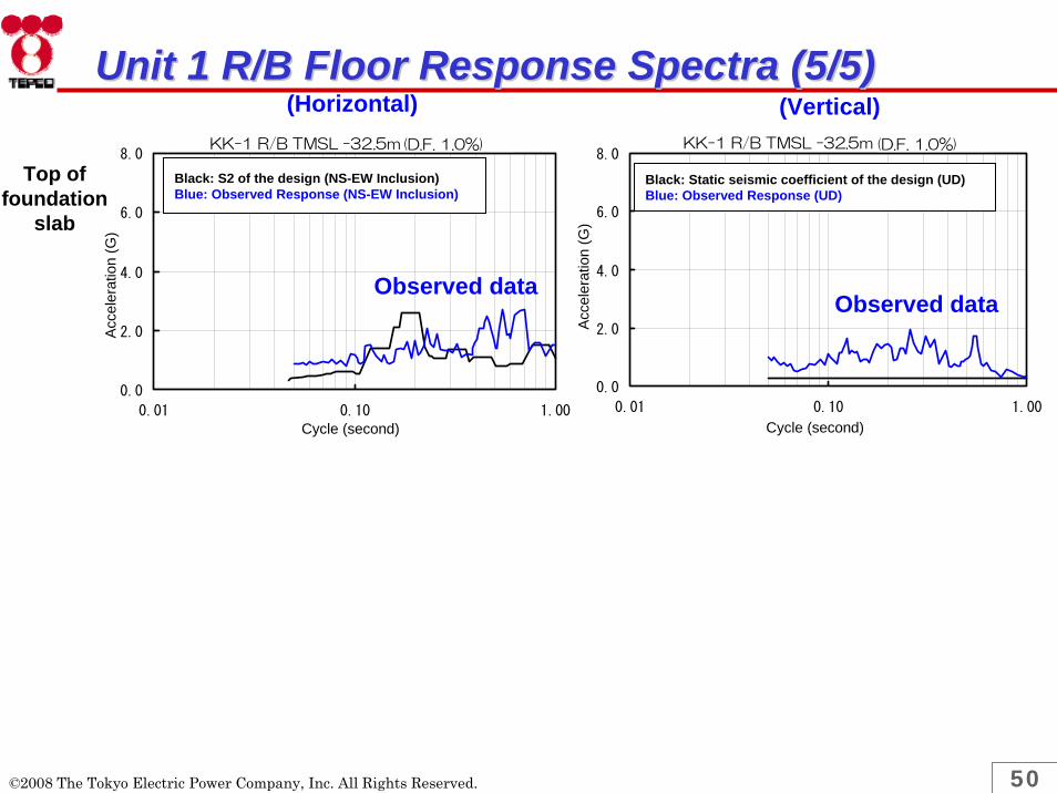
(Horizontal) (Vertical)KK-1 R/B TMSL -32.5m(減衰1.0%)
0.0
2.0
4.0
6.0
8.0
0.01 0.10 1.00周期(秒)
加速
度(G
)
建設時設計地震動(NS,EW包絡)
観測波(NS,EW包絡)
KK-1 R/B TMSL -32.5m(減衰1.0%)
0.0
2.0
4.0
6.0
8.0
0.01 0.10 1.00
周期(秒)
加速
度(G
)
建設時静的震度(上下)
観測波(上下)
Observed dataObserved data
Top of foundation
slab
Unit 1 R/B Floor Response Spectra (5/5)Unit 1 R/B Floor Response Spectra (5/5)
©2008 The Tokyo Electric Power Company, Inc. All Rights Reserved.
Acce
lera
tion
(G)
Acce
lera
tion
(G)
Cycle (second) Cycle (second)
Black: S2 of the design (NS-EW Inclusion)Blue: Observed Response (NS-EW Inclusion)
Black: Static seismic coefficient of the design (UD)Blue: Observed Response (UD)
(D.F. 1.0%)(D.F. 1.0%)

51
Reactor vessel
(1.0, 1.0)
Containment vessel(1.0, 1.0)
Reactor building(5.0, 5.0)
Reactor pedestal (5.0, 5.0)
Reactor shielding wall(5.0, 5.0)
Reactor building
Reactor shielding
wall
Reactor pedestal Containment vessel
Parentheses indicate damping factor [%](Horizontal, Vertical)
Seismic Response Analysis of Seismic Response Analysis of Unit 1 Large Component (1/2)Unit 1 Large Component (1/2)
Reactor vessel
©2008 The Tokyo Electric Power Company, Inc. All Rights Reserved.

52
(Reactor internals analysis model)
Control rod guide tube(1.0, 1.0)
Control rod drive mechanism housing(3.5, 1.0)
Reactor internals (outage state) horizontal direction analysis model
Parentheses indicate damping factor [%](Horizontal, Vertical)
Seismic Response Analysis of Seismic Response Analysis of Unit 1 Large Component (2/2)Unit 1 Large Component (2/2)
©2008 The Tokyo Electric Power Company, Inc. All Rights Reserved.
Core Shroud(1.0, 1.0)

53
Main Steam Piping AnalysisMain Steam Piping Analysis
Main steam isolation valve
Primary containment
vessel penetration
Reactor pressure vessel
Main steam safety relief
valve
©2008 The Tokyo Electric Power Company, Inc. All Rights Reserved.
Condition Design This Evaluation
Pressure ←
←
←
←
←
2.0%
Earthquake motions by simulation
Temperature
Diameter
Thickness
Material
Damping Coefficient
Input
87.90kg/cm2
302℃
660.40mm(main pipe)
33.30mm(main pipe)
STS49(STS480 equivalent)(main pipe)
0.5%
Static Seismic Coefficient, Design earthquake motions

54
Residual Heat Removal System Piping AnalysisResidual Heat Removal System Piping AnalysisReactor Pressure Vessel
Primary containment vessel penetration
©2008 The Tokyo Electric Power Company, Inc. All Rights Reserved.
Condition Design This Evaluation
Pressure 87.90kg/cm2 ←
Temperature 302℃ ←
Diameter 318.50mm ←
Thickness 21.40mm ←
Material STS42 (STS410 equivalent) ←
Damping Coefficient
0.5% 2.5%
Input Static Seismic Coefficient, Design earthquake motions
Earthquake motions by simulation

55
Shroud Support Leg AnalysisShroud Support Leg Analysis
©2008 The Tokyo Electric Power Company, Inc. All Rights Reserved.
Conditions Design This Evaluation
Temperature 297℃ ←
Material NCF1-P(NCF600-P equivalent) ←
Input Output of the coupled model response analysis of reactor building and large component using the design earthquake motions
Output of the coupled model response analysis of reactor building and large component using the earthquake motions by simulation

56
Residual Heat Removal Pump AnalysisResidual Heat Removal Pump Analysis
Residual heat removal pump installation level
©2008 The Tokyo Electric Power Company, Inc. All Rights Reserved.
Conditions Design This Evaluation
Temperature
Material
Input
- 66℃
SNCM439 ←
Static Seismic Coefficient, Design earthquake motions
Earthquake motions by simulation

57
Reactor Pressure Vessel Foundation Bolt AnalysisReactor Pressure Vessel Foundation Bolt Analysis
©2008 The Tokyo Electric Power Company, Inc. All Rights Reserved.
Conditions Design This Evaluation
Temperature
Material
Input
57℃ ←
SNCM 8 (SNCM439 equivalent) ←
Output of the coupled model response analysis of reactor building and large component using the design earthquake motions
Output of the coupled model response analysis of reactor building and large component using the earthquake motions by simulation

58
Primary Containment Vessel AnalysisPrimary Containment Vessel Analysis
©2008 The Tokyo Electric Power Company, Inc. All Rights Reserved.
Conditions Design This Evaluation
Temperature
Material
Input
171℃ ←
SGV49 (SGV480 equivalent) ←
Output of the coupled model response analysis of reactor building and large component using the design earthquake motions
Output of the coupled model response analysis of reactor building and large component using the earthquake motions by simulation

59
Concluding RemarksConcluding Remarks
©2008 The Tokyo Electric Power Company, Inc. All Rights Reserved.

60
Concluding RemarksConcluding RemarksTEPCO has submitted the plan for mechanical, electrical and I&C components installed in Unit 7, in response to the instruction issued by NISA
The soundness of representative equipment is analytically confirmed.
TEPCO keeps conducting such analyses.
Lessons learned during the inspections and restorations are to be deployed to the plans for the other units.
©2008 The Tokyo Electric Power Company, Inc. All Rights Reserved.

61

62
ReferencesReferences

63
Seismic Response AnalysesSeismic Response Analysesof Componentsof Components
©2008 The Tokyo Electric Power Company, Inc. All Rights Reserved.

64
Outline of the Seismic Response AnalysisOutline of the Seismic Response Analysis
Structural StrengthThe allowable stress condition IIIAS
Evaluation pointFixed parts (foundation bolts, legs, etc) with possible large seismic loads
Parts with relatively small design margins
Dynamic Functionality
Comparison between the response acceleration and the functionality-confirmed acceleration
Criteria
The 1991 addendum to JEAG4601
Additional test results
©2008 The Tokyo Electric Power Company, Inc. All Rights Reserved.

65
Concept of the Structural Strength AnalysisConcept of the Structural Strength Analysis
Margin evaluated reasonably using a method within the scope of the standards
Conduct analyses equivalent to design analyses, considering morereasonable evaluation within the allowable limits specified by codes and standards
Simplified analysis : components with relatively large margins
Detailed analyses : components with relatively small margins
Tolerance(IIIAS: Criteria limiting plastic collapse)
Actual value at which plastic collapse occurs
Simplified analysis
Analysis equivalent to design analysis
Detailed analysis
Actual responseConservative screening
Applying realistic damping coefficient
Time history analysis Improved modelsuch as FEM
▽Plastic collapse does not occur in reality
Actual response
Equipment AEquipment BEquipment AEquipment B
Equipment AEquipment BEquipment AEquipment B
Equipment AEquipment B Equipment AEquipment B
©2008 The Tokyo Electric Power Company, Inc. All Rights Reserved.

66
Structural Strength Analysis Methods (1/6)Structural Strength Analysis Methods (1/6)A. Simplified analysis (Response magnification method, etc.)
Large-sized equipment (containment vessel, reactor pressure vessel, reactor internals)Seismic force(acceleration, shear force, moment, and axial force) from building-equipment coupled response analysis.The ratio of the calculated seismic force to the design seismic force is multiplied by the design stress.
Equipment installed on floorsThe ratio of the floor response spectrum of this earthquake to the design floor response spectrum is multiplied by the design stress.
B. Analyses equivalent to design analysesLarge-sized equipment and equipment installed on floors
Equipment with a relatively small margin in the simplified analysis is subject to analysis equivalent to design analysis.
PipingSpectrum model method.
C. Detailed analysesEquipment not meeting the design criteria in the design analysis
Finite element method, time history response analysis, realistic damping coefficient, etc.
©2008 The Tokyo Electric Power Company, Inc. All Rights Reserved.

67
Structural Strength Analysis Methods (2/6)Structural Strength Analysis Methods (2/6)Seismic response analysis of large
equipment Seismic response analysis of buildings
Calculating the seismic force (acceleration, shear force, moment, axial force)
Calculating the floor response spectrum- No 10% widening- Observation data are used for the floor on which the earthquake
was observed
A. Simplified analysis
(Analysis using the response magnification method*, etc.)
B. Analysis equivalent to design analysis (spectrum model method)
Equal to or below the criteria?
B. Analysis equivalent to design analysis (spectrum model method, etc.)
End of analysis
Equal to or below the criteria?
Equal to or below the criteria?
C. Detailed analysis C. Detailed analysis
Yes
No
No No
Yes
Yes
Equipment
Piping
Confirming that the functionality can be maintained
Equal to or below the criteria?
End of analysis
No Yes
A. Simplified analysis
B. Analysis equivalent to design analysis
C. Detailed analysis
©2008 The Tokyo Electric Power Company, Inc. All Rights Reserved.

68
Simplified Analysis (Response Magnification Method)Structural Strength Analysis Methods (3/6)Structural Strength Analysis Methods (3/6)
(Response Ratio)Equipment for which acceleration, shear force, moment, and axial force are used to calculate stress : e.g. reactor pressure vessels and reactor internals
‒ Response ratio = Ratio of the seismic force based on the observation data to the design seismic force (Response ratio will be calculated for acceleration, shear force, moment, and axial force)
Equipment for which horizontal acceleration and vertical acceleration are used to calculate stress : e.g. pump foundation bolts
‒ Response ratio = Ratio of the square root of sum of squares of the horizontal acceleration and vertical acceleration based on the observation data to the square root of sum of squares of the design horizontal acceleration and vertical acceleration
©2008 The Tokyo Electric Power Company, Inc. All Rights Reserved.
Stress calculated based on the observation data of the earthquake
Design stress(seismic stress and non-seismic stress)
Response ratioX=
Stress calculated based on the observation data of the earthquake
Design stress(non-seismic stress)
Design stress(seismic stress)
X= + Response ratio

69
Structural Strength Analysis Methods (4/6)Structural Strength Analysis Methods (4/6)Conditions to take into account as necessary in “analysis equivalent to design analysis”
Analysis methods and parameters, the validity of which has been verified through tests and researches
Revision of damping coefficients (see the next page)
Combining the horizontal dynamic response with the vertical dynamic response using the square root-of-sum-of-squares method
Horizontal floor response spectrum
Analyzing the NS and EW floor response spectrums separately
Fine-tuning the analysis models
Revising the detailed conditions, such as support rigidity
Incorporating operating status
Applying conditions taking into account the operating status, e.g. with or without fuel loading
Setting the allowable stress according to the operating temperature
©2008 The Tokyo Electric Power Company, Inc. All Rights Reserved.

70
Structural Strength Analysis Methods (5/6)Structural Strength Analysis Methods (5/6)
Damping Factor (%)Equipment
Horizontal Vertical
Welded structures 1.0 1.0Bolted and riveted structures 2.0 2.0Mechanical equipment, such as pumps and fans 1.0 1.0
Electric panels 4.0 1.0Fuel assemblies 7.0 1.0Control rod drives 3.5 1.0Piping systems 0.5~3.0 0.5~3.0Spent fuel storage racks 7.0 1.0Fuel handling machines 1.5~2.0 1.5~2.0Reactor building ceiling cranes 2.0 2.0
©2008 The Tokyo Electric Power Company, Inc. All Rights Reserved.

71
Structural Strength Analysis Methods (6/6)Structural Strength Analysis Methods (6/6)
Conditions to take into account as needed in “detailed analysis”
Time history analysis
Applying time history analysis instead of the spectrum model method
More realistic damping coefficients
Applying the results of researches
Analyzing damping by the dissipation energy method
Applying the finite element method
Applicable when the validity thereof is verified based on experiments, etc. (JEAG4601)
Applicable under JEAG4601
Applicable under JEAG4601
©2008 The Tokyo Electric Power Company, Inc. All Rights Reserved.

72
Dynamic FunctionalityDynamic FunctionalityComparison with the functionality-confirmed acceleration
Response acceleration vs. functionality-confirmed acceleration
Functionality-confirmed acceleration
- 1991 Addendum to JEAG4601
- The vertical functionality-confirmed acceleration was specified and the horizontal value was revised based on test results. (The current JEAG specifies the horizontal acceleration only).
Relative displacement of the fuel assemblies vs. functionality-confirmed relative displacement for control rod insertion
Functionality-confirmed relative displacement
- Functionality-confirmed relative displacement, at which rod insertion performance has been verified through testing
©2008 The Tokyo Electric Power Company, Inc. All Rights Reserved.

73
Unit 7 Fuel Cladding Tube StressUnit 7 Fuel Cladding Tube Stress• Outline of Evaluation
– Allowable stress state IIIAS as set forth in JEAG4601-1991 • For primary stress: 0.7Su (tensile strength)
– Simple elastic analysis using thick-walled cylinder model– Stress based on shear strain energy theory– Evaluated statistically giving consideration to statistical distribution of values
including fuel rod dimensions, internal pressure and coolant pressure
Beginning of life
Middle of life
End of life
Support grid interval
Ratio to allowable stress
0.35(0.35)
0.21(0.21)
0.22(0.22)
Maximum design values comparison(Maximum value at 95% reliability)
Numbers in parentheses are values of existing evaluation.
Sufficient margin with respect to evaluation criteria
Note: In JEAG4601, with respect to primary + secondary stress, and primary + secondary + peak stress, “this is a product for which fuel cladding pipe material, dimensions, shape, etc. have strict tolerances, and in the current fuel design, when evaluated primary + secondary stress, and primary + secondary + peak stress the results had sufficient margin, and are thought not to greatly differ from the primary stress evaluation results.” (JEAG4601-1991 Supplement Edition). Therefore, additional evaluation is not required.
©2008 The Tokyo Electric Power Company, Inc. All Rights Reserved.


![Crustal structure of the Java margin from seismic ...eprints.uni-kiel.de/3071/1/jgrb12868.pdf[1] Seismic investigations across the convergent Sunda margin off Indonesia provide a detailed](https://img.pdfslide.net/doc/110x75/5d52bf3788c993383f8b6c3a/crustal-structure-of-the-java-margin-from-seismic-1-seismic-investigations.jpg)