Embed Size (px)
Citation preview
Strojarstvo 52 (5) 577-587 (2010) M. PUŠKÁR et. al., Output Performance Increasing... 577Output Performance Increasing... 577 577
CODEN STJSAO ISSN 0562-1887 ZX470/1479 UDK 621.432.4.053/.057
Preliminary noteAll high-efficiency engines are inclined to destruction tendencies resulting from detonation combustion. Most often the producers of engines solve this problem with limitation of maximum output performance but, in this, there is an efficiency decrease of fuel utilization. However, detonation combustion can also be useful because if it is kept to a certain level, then detonation combustion helps considerably in an additional increase of output performance. This article defines the termination expressed in a number of detonation units per overridden distance of track carried out by a single-track vehicle. Just for this limit, there is a detonation combustion beneficial to increase an output performance and not cause destruction in the engineering parts of an engine. The limit gives an idea about the influence of individual factors on detonation combustion as well as the influence on this combustion in obtaining maximum values and behaviours of engine output performance and torque with dependence on engine speed.
Povećanje performansi dvotaktnog Otto motora optimiranjem detonacijskog izgaranja
Prethodno priopćenjeSvi visoko učinski motori naginju detonacijskom načinu izgaranja. Mnogi proizvođači motora rješavaju taj problem ograničavanjem maksiomalnih izlaznih performansi motora, a što ima za posljedicu smanjenje stupnja iskoristivosti tog motora. No ipak detonacijsko izgaranje može biti i od koristi, jer ako se ono podržava na stvarnoj razini, tada takav način izgaranja omogućava primjetno povećavanje izlaznih performansi motora. Ovaj članak definira ograničenje broja detonacijskih jedinica nad cjelokupnim putanjom, koje je prešlo vozilo. Upravo za to ograničenje postoji benefit detonacijskog izgaranja u smislu povećavanja izlaznih performansi, a pri čemu ne dolazi do oštećivanja bilo kojeg drigog dijela motora. To ograničenje daje ideju o utjecaju pojedinačnih faktora na detonacijsko izgaranje, kao i utjecaj ovakvog načina izgaranja na dobivanje maksimalnih vrijednosti kao i na ponašanja izlaznih performansi motora i momenta ovisno o brzini motora.
michal PUŠKÁR and Peter BiGOŠ
KKDal SjF TU Košice,Letná 9, 040 01 KošiceSlovak Republic
KeywordsDetonation combustion Engine output performance
Ključne riječiDetonacijsko izgaranje Izlazne performanse motora
Received (primljeno): 2010-03-08 Accepted (prihvaćeno): 2010-07-25
Output Performance Increase of Two-stroke Combustion Engine with Detonation Combustion Optimization
1. Introduction and Aims
An arrangement of combustion space and plug replacement influence the shape and distribution of flame; therefore, they also influence heat and cylinder pressure developments. In petrol engines, the preparation of mixture begins at the time of a cylinder filling and continues during compression and finishes close before combustion. An ignition rate depends on a kind of mixture, combustion development and mixture movement. By means of the shape of combustion space it is possible to whirl up a mixture and so regulate combustion development. This shape influences an indicated pressure, efficiency and hard running engine. An advantage for shape of combustion space is evaluated together with a critical compression ratio, resulting in a detonation resistance. The value of a critical compression ratio should be as high as possible from the point of view of output performance and thermal efficiency of engine.
At a high level of mixture compression a faster and more perfect fire-through occurs, creating a higher effective pressure on a piston and, thus, it is possible to reach a high engine speed. That is why antiknock spacings (squishes) are used for combustion spaces. The basis is the antiknock spacing of approximately 0.4 to 1.2 mm. This spacing is between a piston and a cylinder head, if a piston is in TDC. At the end of a compression stroke, the spacing is reduced quickly and a mixture leaks from this place in the direction of the piston centre. The intense flow is evocated with this. The flow accelerates combustion and prevents a detonation occurrence. There are also other influences impacting the critical compression ratio, as for example: cooling, the shape of ignition curve and others. If compared, these impacts have to be kept as constant or optimal value.
A normal combustion is a controlled one through a mixture of fuel and air in a combustion chamber. It is a
578 M. PUŠKÁR et. al., Output Performance Increasing... Strojarstvo 52 (5) 577-587 (2010)
stable combustion, which develops at a spark plug and continues in a combustion chamber in a three-dimensional way.
A detonation is a phenomenon, which is classified as an abnormal combustion. It is an auto-ignition of a residual tresh mixture in a combustion chamber. It occus after normal combustion. At an initial phase, there is normal mixture combustion, then under the influence of high pressure and heat there are spontaneous ignitions, so detonation combustion occurs.
Detonations induce high pressure in a combustion chamber. This pressure takes a very short-time. In a combustion chamber, the pressure behaviour seems to be normal with an increasing development and then the pressure increases evidently. The rapid increase of pressure is indicated as excess compared with a normal one. These excesses exemplify the pressure, caused detonation combustion. Also this rapid increase of pressure evocates forces in a combustion chamber, which induces resonance in an engine construction. These resonances are characteristic in detonation combustion. The noise or vibrations present the phenomenon, which is recorded which a detonation counter.
It is important to know that detonation need not be necessarily destructive. Many engines operate with a certain number of detonations. Some engines can withstand strong detonations a very long time without destruction. The controlled detonation combustion is useful because it increases engine output performance. The aim of this contribution is to find a limit where an tested engine produces the highest performance, but detonation combustion does not damage its design components. Furthermore, the influence of detonation combustion on maximum values of output performance and torque as well as their behaviours depending on an engine speed, are taken into consideration.
2. Experimental Models and Devices
Detonations influence the design of a combustion chamber (shape, size, geometry, replacement of spark plug), compression ratio, the proportion of air and fuel in a combustion mixture, shape of ignition curve, atmospheric conditions and octane number of fuel. If the surface of a piston or the combustion space is damaged or destroyed, detonation combustion also starts in such conditions, which are not critical, but this damage affects directly as an initiator of detonation combustion. The engines, which are exposed to incodased detonation combustion, tend to overheat, which initiates an avalanche effect. With higher temperature, there is faster detonation combustion and faster destruction. The piston absorbs a great deal of heat; on four sides tit dilates, caouseing dilatation destruction. The combustion temperatures are very high at the moment
of detonation ignition, which causes a melting down of the piston and combustion space materials.
For this reason it is difficult to determine theoretically the limit for detonation combustion and then to prove its authenticity for a two-stroke petrol engine. Although there is software for a modelling of processes inside a cylinder and in an exhaust system during combustion, the real results are performed seriously. That is why the experiment was used to achieve the main goal. It is necessary to choose the experimental model for measurements. The development was carried out with this experimental model. Further, there is a need to choose the measurement devices (to provide feedback, to give information about real output proposition for concrete change in detonation combustion).
2.1. Experimental Models
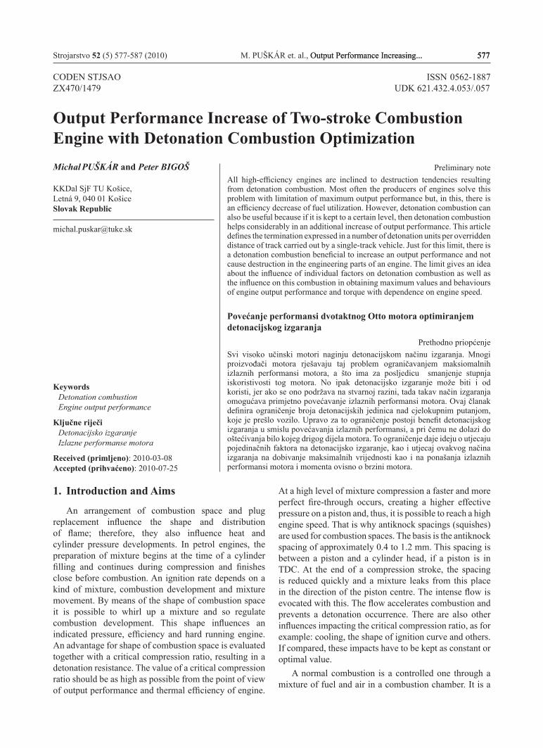
The motorcycle Aprilia RS 125 with a racing modification was used as the experimental model. This single-track vehicle is equipped with a two-stroke engine ROTAX 122 (Figure 1). In Table 1 there are the basic technical parameters for this engine.
Figure 1. Engine ROTAX 122Slika 1. Motor ROTAX 122
As results of long-time experience and motorcycle firms’ research, the compact semi-spherical combustion space is the most suitable. This shape, with small differences, is used for the large spectrum of motorcycle series as well as special two-stroke racing vehicles. For the requirements of the measurement, this shape was also applied in the combination of a standard piston with a vault.
The combustion development is presented in the introduction of paragraph 1.
Strojarstvo 52 (5) 577-587 (2010) M. PUŠKÁR et. al., Output Performance Increasing... 579Output Performance Increasing... 579 579
Table 1. Technical Parameters of Engine ROTAX 122Tablica 1. Tehnički parametri motora ROTAX 122
Type / Tip
Single-cylinder, two-stroke engine, liquid cooled, membrane filled, an electrical-controlled exhaust power valve / Jednocilindričan, dvotaktni motor, hlađen tekućinom, punjen u
membranama, električno kontroliran ventil ispuha
Displacement volume / Stapajni
volumen124.8 cm3
Bore x Stroke / Promjer x hod 54 x 54.5 mm
Carburator / Karburator Dell’Orto PHBH 28 BD
In Table 2 the compression ratios are given. The variations of antiknock spacing (paragraph 1) achieved the differences. The compression ratio, used in the article (Table 2), represents an effective compression ratio, which is calculated according to the relation:
(1)
where: VC – compression volume VS – stroke volume
An ignition curve, the shape of which is given with a graphic representation by means of the pre-ignition degrees depending on engine speed, was developed considerably. The newest and the latest shapes of ignition curves are common curves, which eliminate inadequacies, e.g. problems with filling for the concrete mode of an engine speed. For the needs of the experimental measurements the SP curve (declared by a producer) was used. It is provided for this motorcycle as a special part. This curve is very similar to the serial-one provided for the motorcycle since the 2006 year of production.
Table 2. Input conditions Tablica 2. Ulazni uvjeti
No. / Broj
Atmospheric Conditions / Atmosferski uvjeti
Compression Ratio / Omjer
kompresijeTemperature / Temperatura,
°C
Pressure / Tlak, kPa
Humidity / Relativna vlažnost,
%
1 27 97.3 37 14.462 21.2 98.2 36 14.433 17 97.5 65 14.674 18.8 97.2 44 14.71
2.2. Experimental Devices
Two testing and measuring devices were developed for the experimental measurements.
Engine Watch and Control System – EW&CThat is a data-recording system, i.e. a device which
scans and stores information during a motorcycle ride (in real conditions, in real loading). This device enables a diagnosis of parameters of a two-stroke combustion engine: an output performance, a torque and their behaviours, a temperature of exhaust system and its behaviour and other characteristics. A number and a kind of scanned parameters are related to the types and a number of sensors, which are installed on the combustion engine.
In Figure 3 there is the block diagram for data measurement, operating and evaluation. The engine activity record with dependence on time is the result of this system. The principle of EW&C system is in the measurement of the engine is instantaneous speed, an instantaneous temperature of exhaust system and scanning of an active speed gear or further parameters. The system does a functional record of engine activity on the basis of scanned and entered data (a wheel circumference, gear ratios of individual speed gears, a curve of air resistance and a motorcycle weight).
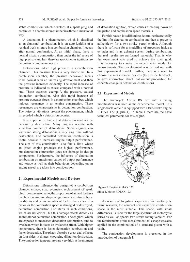
This record is stored in the memory of the EW&C system. After finishing the measurement, it is possible to copy the record by means of the parallel port into PC (Figure 2). On PC display (Figure 8) there is a record of engine activity with dependence on a time axis, graphically presented (by means of the software which is a component of EW&C system). Every point of the record covers an instantaneous speed, a temperature of exhaust system and an output at a crankshaft end.
Figure 2. Engine watch and control aystemSlika 2. Nadzorni i upravljački sustav motora
580 M. PUŠKÁR et. al., Output Performance Increasing... Strojarstvo 52 (5) 577-587 (2010)
Figure 3. Block diagram of EW&C systemSlika 3. Blok-dijagram kočnice motora
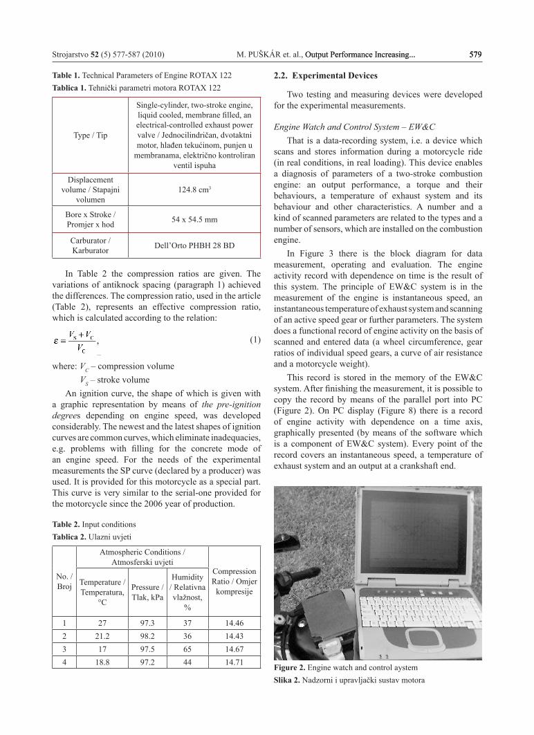
Detonation CounterIn Figure 4 there is the detonation counter, which
was used for the measurement of detonations. It was developed and produced by the racing department of Honda HRC company. The detonation counter sensor picks up an irregular combustion as the detonations in the engine and provides a number of detonation units. In Figure 9 this number on the display is displayed.
Legend: 1. Detonation Counter / Brojač detonacije, 2.Plug Cap / Kapa svjećice, 3.Spark Plug / Svjećica, 4. Sensor Assy / Assy osjetnik, 5. Detonation Counter Unit Stay / Jedinica brojača detonacije, 6. Washer / Podloška, 7. Wire Harness / Žičani spojevi, 8. Sub Harness / Pomoćni žičani spojevi.Figure 4. Detonation counter kitSlika 4. Oprema za brojanje detonacije
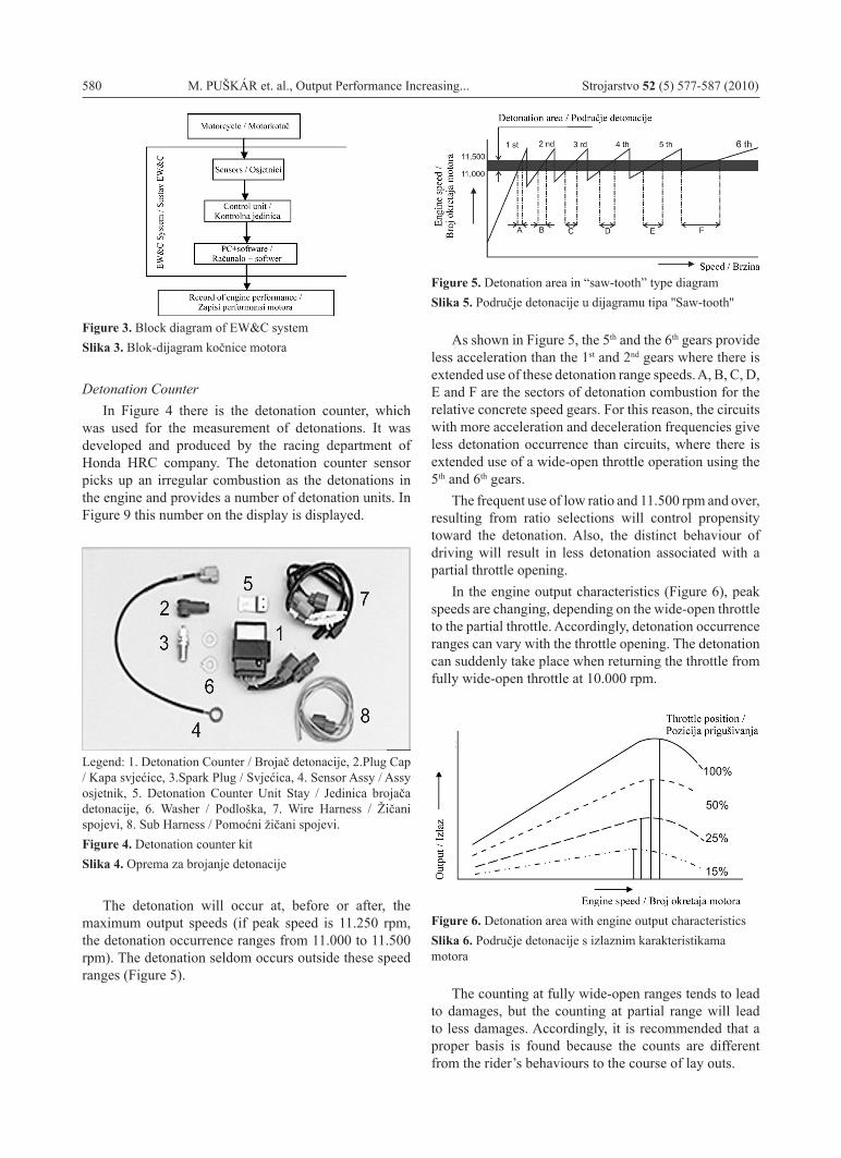
The detonation will occur at, before or after, the maximum output speeds (if peak speed is 11.250 rpm, the detonation occurrence ranges from 11.000 to 11.500 rpm). The detonation seldom occurs outside these speed ranges (Figure 5).
Figure 5. Detonation area in “saw-tooth” type diagramSlika 5. Područje detonacije u dijagramu tipa ''Saw-tooth''
As shown in Figure 5, the 5th and the 6th gears provide less acceleration than the 1st and 2nd gears where there is extended use of these detonation range speeds. A, B, C, D, E and F are the sectors of detonation combustion for the relative concrete speed gears. For this reason, the circuits with more acceleration and deceleration frequencies give less detonation occurrence than circuits, where there is extended use of a wide-open throttle operation using the 5th and 6th gears.
The frequent use of low ratio and 11.500 rpm and over, resulting from ratio selections will control propensity toward the detonation. Also, the distinct behaviour of driving will result in less detonation associated with a partial throttle opening.
In the engine output characteristics (Figure 6), peak speeds are changing, depending on the wide-open throttle to the partial throttle. Accordingly, detonation occurrence ranges can vary with the throttle opening. The detonation can suddenly take place when returning the throttle from fully wide-open throttle at 10.000 rpm.
Figure 6. Detonation area with engine output characteristicsSlika 6. Područje detonacije s izlaznim karakteristikama motora
The counting at fully wide-open ranges tends to lead to damages, but the counting at partial range will lead to less damages. Accordingly, it is recommended that a proper basis is found because the counts are different from the rider’s behaviours to the course of lay outs.
Strojarstvo 52 (5) 577-587 (2010) M. PUŠKÁR et. al., Output Performance Increasing... 581Output Performance Increasing... 581 581
The criteria for a detonation counter Honda HRC producer of the device recommends two
units for an overridden kilometre of a race track.In Japan on Suzuka Circuit a device was tested with
twelve units for one circuit, which is approximately six kilometres in length. Certainly, this is only the recommendation and it is enough apart from a limit where detonation combustion reaches a limiting value and has not damaged an engine design yet.
3. Experimental Results
The performed measurements are intended for the analysis of the detonation combustion influence with an output characteristic in consideration of the defined aim.
The aim of consecutive measurements determined the limit, expressed in a number of detonation units per overridden kilometre, where the combustion is beneficial and helps to increase output performance and does not cause destruction in the design components of an engine.
In the experimental model the diagnostic devices were applied, described in the above-mentioned paragraph. The measurements were performed for two racing circuits: the Hungaroring in Hungary and the Autodrom Most in the Czech Republic. The obtained results, which are presented in this paragraph, were verified with multiple consecutive measurements to prevent a potential random error.
In the introduction of previous paragraph the factors which influence detonation combustion are described. They are the design of a combustion chamber (shape, size, geometry, replacement of spark plug), compression ratio, the proportion of the combustion mixture, shape of ignition curve, the atmospheric conditions and octane number of a fuel.
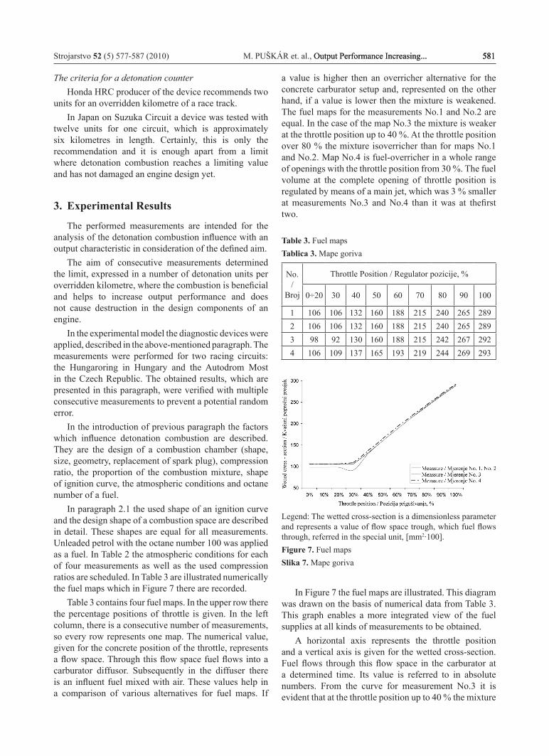
In paragraph 2.1 the used shape of an ignition curve and the design shape of a combustion space are described in detail. These shapes are equal for all measurements. Unleaded petrol with the octane number 100 was applied as a fuel. In Table 2 the atmospheric conditions for each of four measurements as well as the used compression ratios are scheduled. In Table 3 are illustrated numerically the fuel maps which in Figure 7 there are recorded.
Table 3 contains four fuel maps. In the upper row there the percentage positions of throttle is given. In the left column, there is a consecutive number of measurements, so every row represents one map. The numerical value, given for the concrete position of the throttle, represents a flow space. Through this flow space fuel flows into a carburator diffusor. Subsequently in the diffuser there is an influent fuel mixed with air. These values help in a comparison of various alternatives for fuel maps. If
a value is higher then an overricher alternative for the concrete carburator setup and, represented on the other hand, if a value is lower then the mixture is weakened. The fuel maps for the measurements No.1 and No.2 are equal. In the case of the map No.3 the mixture is weaker at the throttle position up to 40 %. At the throttle position over 80 % the mixture isoverricher than for maps No.1 and No.2. Map No.4 is fuel-overricher in a whole range of openings with the throttle position from 30 %. The fuel volume at the complete opening of throttle position is regulated by means of a main jet, which was 3 % smaller at measurements No.3 and No.4 than it was at thefirst two.
Table 3. Fuel mapsTablica 3. Mape goriva
No. /
Broj
Throttle Position / Regulator pozicije, %
0÷20 30 40 50 60 70 80 90 100
1 106 106 132 160 188 215 240 265 2892 106 106 132 160 188 215 240 265 2893 98 92 130 160 188 215 242 267 2924 106 109 137 165 193 219 244 269 293
Legend: The wetted cross-section is a dimensionless parameter and represents a value of flow space trough, which fuel flows through, referred in the special unit, [mm2·100].Figure 7. Fuel mapsSlika 7. Mape goriva
In Figure 7 the fuel maps are illustrated. This diagram was drawn on the basis of numerical data from Table 3. This graph enables a more integrated view of the fuel supplies at all kinds of measurements to be obtained.
A horizontal axis represents the throttle position and a vertical axis is given for the wetted cross-section. Fuel flows through this flow space in the carburator at a determined time. Its value is referred to in absolute numbers. From the curve for measurement No.3 it is evident that at the throttle position up to 40 % the mixture
582 M. PUŠKÁR et. al., Output Performance Increasing... Strojarstvo 52 (5) 577-587 (2010)
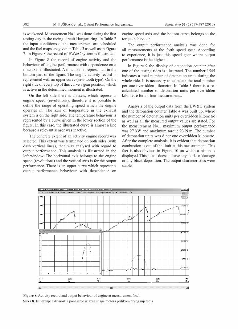
is weakened. Measurement No.1 was done during the first testing day in the racing circuit Hungaroring. In Table 2 the input conditions of the measurement are scheduled and the fuel maps are given in Table 3 as well as in Figure 7. In Figure 8 the record of EW&C system is illustrated.
In Figure 8 the record of engine activity and the behaviour of engine performance with dependence on a time axis is illustrated. A time axis is represented in the bottom part of the figure. The engine activity record is represented with an upper curve (saw-tooth type). On the right side of every top of this curve a gear position, which is active in the determined moment is illustrated.
On the left side there is an axis, which represents engine speed (revolutions); therefore it is possible to define the range of operating speed which the engine operates in. The axis of temperature in the exhaust system is on the right side. The temperature behaviour is represented by a curve given in the lower section of the figure. In this case, the illustrated curve is almost a line because a relevant sensor was inactive.
The concrete extent of an activity engine record was selected. This extent was terminated on both sides (with dash vertical lines), then was analysed with regard to output performance. This analysis is illustrated in the left window. The horizontal axis belongs to the engine speed (revolutions) and the vertical axis is for the output performance. There is an upper curve which represents output performance behaviour with dependence on
engine speed axis and the bottom curve belongs to the torque behaviour.
The output performance analysis was done for all measurements at the forth speed gear. According to experience, it is just this speed gear where output performance is the highest.
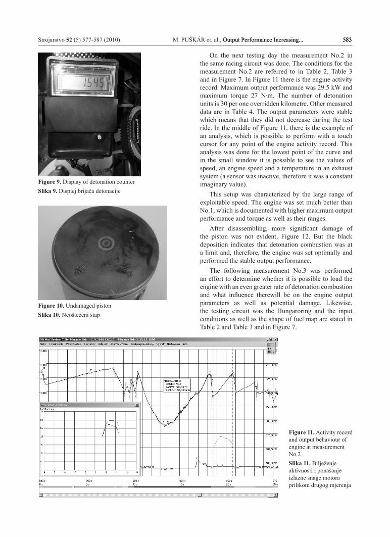
In Figure 9 the display of detonation counter after one of the testing rides is illustrated. The number 1545 indicates a total number of detonation units during the whole ride. It is necessary to calculate the total number per one overridden kilometre. In Table 3 there is a re-calculated number of detonation units per overridden kilometre for all four measurements.
Analysis of the output data from the EW&C system and the detonation counter Table 4 was built up, where the number of detonation units per overridden kilometre as well as all the measured output values are stated. For the measurement No.1 maximum output performance was 27 kW and maximum torque 23 N·m. The number of detonation units was 8 per one overridden kilometre. After the complete analysis, it is evident that detonation combustion is out of the limit at this measurement. This fact is also obvious in Figure 10 on which a piston is displayed. This piston does not have any marks of damage or any black deposition. The output characteristics were stable.
Figure 8. Activity record and output behaviour of engine at measurement No.1Slika 8. Bilježenje aktivnosti i ponašanje izlazne snage motora prilikom prvog mjerenja
Strojarstvo 52 (5) 577-587 (2010) M. PUŠKÁR et. al., Output Performance Increasing... 583Output Performance Increasing... 583 583
Figure 9. Display of detonation counterSlika 9. Displej brijača detonacije
Figure 10. Undamaged pistonSlika 10. Neoštećeni stap
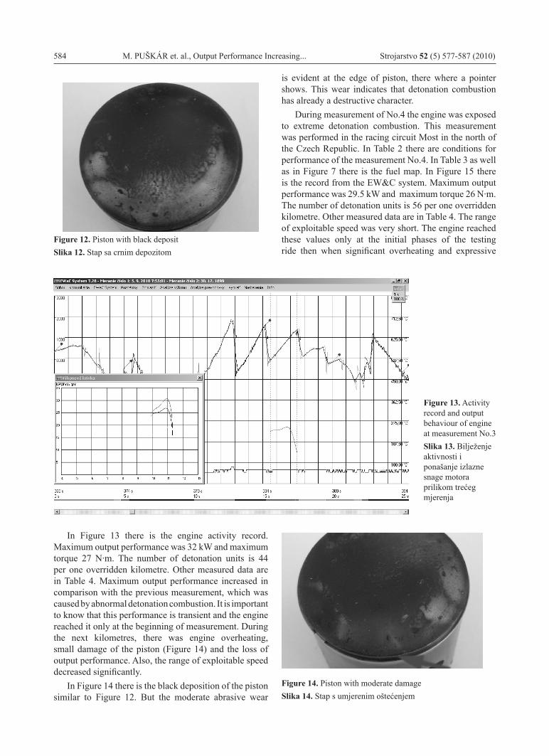
On the next testing day the measurement No.2 in the same racing circuit was done. The conditions for the measurement No.2 are referred to in Table 2, Table 3 and in Figure 7. In Figure 11 there is the engine activity record. Maximum output performance was 29.5 kW and maximum torque 27 N·m. The number of detonation units is 30 per one overridden kilometre. Other measured data are in Table 4. The output parameters were stable which means that they did not decrease during the test ride. In the middle of Figure 11, there is the example of an analysis, which is possible to perform with a touch cursor for any point of the engine activity record. This analysis was done for the lowest point of the curve and in the small window it is possible to see the values of speed, an engine speed and a temperature in an exhaust system (a sensor was inactive, therefore it was a constant imaginary value).
This setup was characterized by the large range of exploitable speed. The engine was set much better than No.1, which is documented with higher maximum output performance and torque as well as their ranges.
After disassembling, more significant damage of the piston was not evident, Figure 12. But the black deposition indicates that detonation combustion was at a limit and, therefore, the engine was set optimally and performed the stable output performance.
The following measurement No.3 was performed an effort to determine whether it is possible to load the engine with an even greater rate of detonation combustion and what influence therewill be on the engine output parameters as well as potential damage. Likewise, the testing circuit was the Hungaroring and the input conditions as well as the shape of fuel map are stated in Table 2 and Table 3 and in Figure 7.
Figure 11. Activity record and output behaviour of engine at measurement No.2Slika 11. Bilježenje aktivnosti i ponašanje izlazne snage motora prilikom drugog mjerenja
584 M. PUŠKÁR et. al., Output Performance Increasing... Strojarstvo 52 (5) 577-587 (2010)
Figure 12. Piston with black depositSlika 12. Stap sa crnim depozitom
In Figure 13 there is the engine activity record. Maximum output performance was 32 kW and maximum torque 27 N·m. The number of detonation units is 44 per one overridden kilometre. Other measured data are in Table 4. Maximum output performance increased in comparison with the previous measurement, which was caused by abnormal detonation combustion. It is important to know that this performance is transient and the engine reached it only at the beginning of measurement. During the next kilometres, there was engine overheating, small damage of the piston (Figure 14) and the loss of output performance. Also, the range of exploitable speed decreased significantly.
In Figure 14 there is the black deposition of the piston similar to Figure 12. But the moderate abrasive wear
Figure 13. Activity record and output behaviour of engine at measurement No.3Slika 13. Bilježenje aktivnosti i ponašanje izlazne snage motora prilikom trećeg mjerenja
Figure 14. Piston with moderate damageSlika 14. Stap s umjerenim oštećenjem
is evident at the edge of piston, there where a pointer shows. This wear indicates that detonation combustion has already a destructive character.
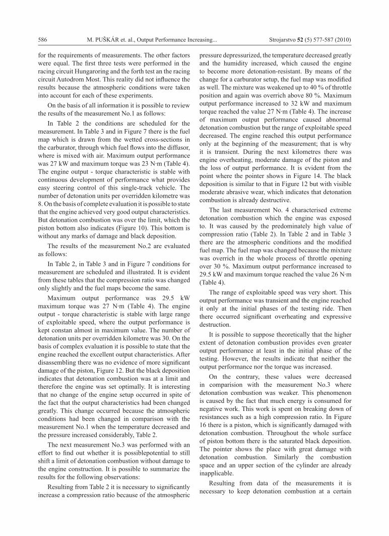
During measurement of No.4 the engine was exposed to extreme detonation combustion. This measurement was performed in the racing circuit Most in the north of the Czech Republic. In Table 2 there are conditions for performance of the measurement No.4. In Table 3 as well as in Figure 7 there is the fuel map. In Figure 15 there is the record from the EW&C system. Maximum output performance was 29.5 kW and maximum torque 26 N·m. The number of detonation units is 56 per one overridden kilometre. Other measured data are in Table 4. The range of exploitable speed was very short. The engine reached these values only at the initial phases of the testing ride then when significant overheating and expressive
Strojarstvo 52 (5) 577-587 (2010) M. PUŠKÁR et. al., Output Performance Increasing... 585Output Performance Increasing... 585 585
Figure 15. Activity record and Output Behaviour of Engine at Measurement No.4Slika 15. Bilježenje aktivnosti i ponašanje izlazne snage motora prilikom četvrtog mjerenja
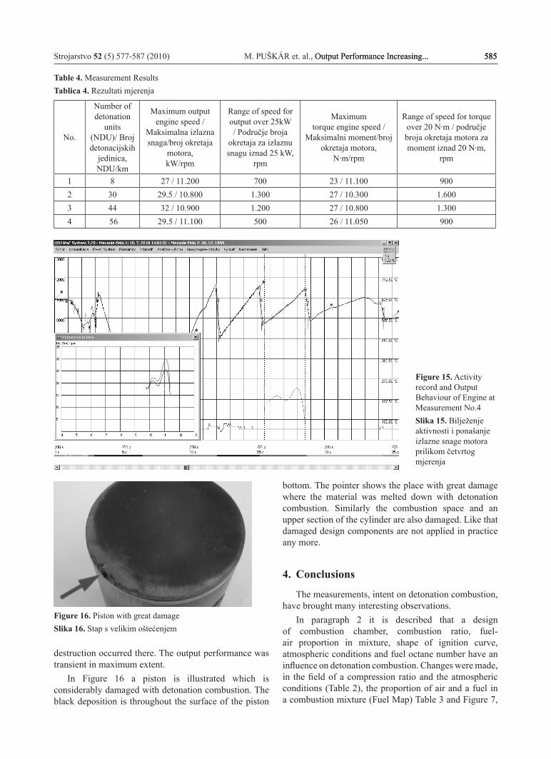
Table 4. Measurement ResultsTablica 4. Rezultati mjerenja
No.
Number of detonation
units (NDU)/ Broj detonacijskih
jedinica, NDU/km
Maximum output engine speed /
Maksimalna izlazna snaga/broj okretaja
motora,kW/rpm
Range of speed for output over 25kW / Područje broja
okretaja za izlaznu snagu iznad 25 kW,
rpm
Maximumtorque engine speed /
Maksimalni moment/broj okretaja motora,
N·m/rpm
Range of speed for torque over 20 N·m / područje broja okretaja motora za moment iznad 20 N·m,
rpm
1 8 27 / 11.200 700 23 / 11.100 9002 30 29.5 / 10.800 1.300 27 / 10.300 1.6003 44 32 / 10.900 1.200 27 / 10.800 1.3004 56 29.5 / 11.100 500 26 / 11.050 900
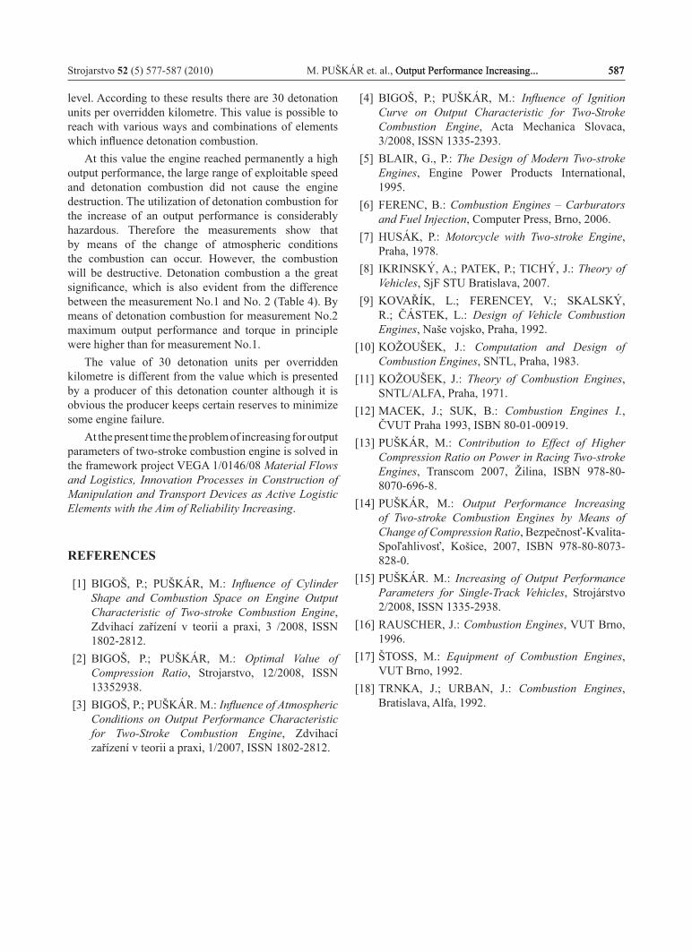
Figure 16. Piston with great damageSlika 16. Stap s velikim oštećenjem
bottom. The pointer shows the place with great damage where the material was melted down with detonation combustion. Similarly the combustion space and an upper section of the cylinder are also damaged. Like that damaged design components are not applied in practice any more.
4. Conclusions
The measurements, intent on detonation combustion, have brought many interesting observations.
In paragraph 2 it is described that a design of combustion chamber, combustion ratio, fuel-air proportion in mixture, shape of ignition curve, atmospheric conditions and fuel octane number have an influence on detonation combustion. Changes were made, in the field of a compression ratio and the atmospheric conditions (Table 2), the proportion of air and a fuel in a combustion mixture (Fuel Map) Table 3 and Figure 7,
destruction occurred there. The output performance was transient in maximum extent.
In Figure 16 a piston is illustrated which is considerably damaged with detonation combustion. The black deposition is throughout the surface of the piston
586 M. PUŠKÁR et. al., Output Performance Increasing... Strojarstvo 52 (5) 577-587 (2010)
for the requirements of measurements. The other factors were equal. The first three tests were performed in the racing circuit Hungaroring and the forth test an the racing circuit Autodrom Most. This reality did not influence the results because the atmospheric conditions were taken into account for each of these experiments.
On the basis of all information it is possible to review the results of the measurement No.1 as follows:
In Table 2 the conditions are scheduled for the measurement. In Table 3 and in Figure 7 there is the fuel map which is drawn from the wetted cross-sections in the carburator, through which fuel flows into the diffusor, where is mixed with air. Maximum output performance was 27 kW and maximum torque was 23 N·m (Table 4). The engine output - torque characteristic is stable with continuous development of performance what provides easy steering control of this single-track vehicle. The number of detonation units per overridden kilometre was 8. On the basis of complete evaluation it is possible to state that the engine achieved very good output characteristics. But detonation combustion was over the limit, which the piston bottom also indicates (Figure 10). This bottom is without any marks of damage and black deposition.
The results of the measurement No.2 are evaluated as follows:
In Table 2, in Table 3 and in Figure 7 conditions for measurement are scheduled and illustrated. It is evident from these tables that the compression ratio was changed only slightly and the fuel maps become the same.
Maximum output performance was 29.5 kW maximum torque was 27 N·m (Table 4). The engine output - torque characteristic is stable with large range of exploitable speed, where the output performance is kept constan almost in maximum value. The number of detonation units per overridden kilometre was 30. On the basis of complex evaluation it is possible to state that the engine reached the excellent output characteristics. After disassembling there was no evidence of more significant damage of the piston, Figure 12. But the black deposition indicates that detonation combustion was at a limit and therefore the engine was set optimally. It is interesting that no change of the engine setup occurred in spite of the fact that the output characteristics had been changed greatly. This change occurred because the atmospheric conditions had been changed in comparison with the measurement No.1 when the temperature decreased and the pressure increased considerably, Table 2.
The next measurement No.3 was performed with an effort to find out whether it is possiblepotential to still shift a limit of detonation combustion without damage to the engine construction. It is possible to summarize the results for the following observations:
Resulting from Table 2 it is necessary to significantly increase a compression ratio because of the atmospheric
pressure depressurized, the temperature decreased greatly and the humidity increased, which caused the engine to become more detonation-resistant. By means of the change for a carburator setup, the fuel map was modified as well. The mixture was weakened up to 40 % of throttle position and again was overrich above 80 %. Maximum output performance increased to 32 kW and maximum torque reached the value 27 N·m (Table 4). The increase of maximum output performance caused abnormal detonation combustion but the range of exploitable speed decreased. The engine reached this output performance only at the beginning of the measurement; that is why it is transient. During the next kilometres there was engine overheating, moderate damage of the piston and the loss of output performance. It is evident from the point where the pointer shows in Figure 14. The black deposition is similar to that in Figure 12 but with visible moderate abrasive wear, which indicates that detonation combustion is already destructive.
The last measurement No. 4 characterised extreme detonation combustion which the engine was exposed to. It was caused by the predominately high value of compression ratio (Table 2). In Table 2 and in Table 3 there are the atmospheric conditions and the modified fuel map. The fuel map was changed because the mixture was overrich in the whole process of throttle opening over 30 %. Maximum output performance increased to 29.5 kW and maximum torque reached the value 26 N·m (Table 4).
The range of exploitable speed was very short. This output performance was transient and the engine reached it only at the initial phases of the testing ride. Then there occurred significant overheating and expressive destruction.
It is possible to suppose theoretically that the higher extent of detonation combustion provides even greater output performance at least in the initial phase of the testing. However, the results indicate that neither the output performance nor the torque was increased.
On the contrary, these values were decreased in comparision with the measurement No.3 where detonation combustion was weaker. This phenomenon is caused by the fact that much energy is consumed for negative work. This work is spent on breaking down of resistances such as a high compression ratio. In Figure 16 there is a piston, which is significantly damaged with detonation combustion. Throughout the whole surface of piston bottom there is the saturated black deposition. The pointer shows the place with great damage with detonation combustion. Similarly the combustion space and an upper section of the cylinder are already inapplicable.
Resulting from data of the measurements it is necessary to keep detonation combustion at a certain
Strojarstvo 52 (5) 577-587 (2010) M. PUŠKÁR et. al., Output Performance Increasing... 587Output Performance Increasing... 587 587
level. According to these results there are 30 detonation units per overridden kilometre. This value is possible to reach with various ways and combinations of elements which influence detonation combustion.
At this value the engine reached permanently a high output performance, the large range of exploitable speed and detonation combustion did not cause the engine destruction. The utilization of detonation combustion for the increase of an output performance is considerably hazardous. Therefore the measurements show that by means of the change of atmospheric conditions the combustion can occur. However, the combustion will be destructive. Detonation combustion a the great significance, which is also evident from the difference between the measurement No.1 and No. 2 (Table 4). By means of detonation combustion for measurement No.2 maximum output performance and torque in principle were higher than for measurement No.1.
The value of 30 detonation units per overridden kilometre is different from the value which is presented by a producer of this detonation counter although it is obvious the producer keeps certain reserves to minimize some engine failure.
At the present time the problem of increasing for output parameters of two-stroke combustion engine is solved in the framework project VEGA 1/0146/08 Material Flows and Logistics, Innovation Processes in Construction of Manipulation and Transport Devices as Active Logistic Elements with the Aim of Reliability Increasing.
REFERENCES
[1] BIGOŠ, P.; PUŠKÁR, M.: Influence of Cylinder Shape and Combustion Space on Engine Output Characteristic of Two-stroke Combustion Engine, Zdvihací zařízení v teorii a praxi, 3 /2008, ISSN 1802-2812.
[2] BIGOŠ, P.; PUŠKÁR, M.: Optimal Value of Compression Ratio, Strojarstvo, 12/2008, ISSN 13352938.
[3] BIGOŠ, P.; PUŠKÁR. M.: Influence of Atmospheric Conditions on Output Performance Characteristic for Two-Stroke Combustion Engine, Zdvihací zařízení v teorii a praxi, 1/2007, ISSN 1802-2812.
[4] BIGOŠ, P.; PUŠKÁR, M.: Influence of Ignition Curve on Output Characteristic for Two-Stroke Combustion Engine, Acta Mechanica Slovaca, 3/2008, ISSN 1335-2393.
[5] BLAIR, G., P.: The Design of Modern Two-stroke Engines, Engine Power Products International, 1995.
[6] FERENC, B.: Combustion Engines – Carburators and Fuel Injection, Computer Press, Brno, 2006.
[7] HUSÁK, P.: Motorcycle with Two-stroke Engine, Praha, 1978.
[8] IKRINSKý, A.; PATEK, P.; TICHý, J.: Theory of Vehicles, SjF STU Bratislava, 2007.
[9] KOVAŘÍK, L.; FERENCEY, V.; SKALSKý, R.; ČÁSTEK, L.: Design of Vehicle Combustion Engines, Naše vojsko, Praha, 1992.
[10] KOŽOUŠEK, J.: Computation and Design of Combustion Engines, SNTL, Praha, 1983.
[11] KOŽOUŠEK, J.: Theory of Combustion Engines, SNTL/ALFA, Praha, 1971.
[12] MACEK, J.; SUK, B.: Combustion Engines I., ČVUT Praha 1993, ISBN 80-01-00919.
[13] PUŠKÁR, M.: Contribution to Effect of Higher Compression Ratio on Power in Racing Two-stroke Engines, Transcom 2007, Žilina, ISBN 978-80-8070-696-8.
[14] PUŠKÁR, M.: Output Performance Increasing of Two-stroke Combustion Engines by Means of Change of Compression Ratio, Bezpečnosť-Kvalita-Spoľahlivosť, Košice, 2007, ISBN 978-80-8073-828-0.
[15] PUŠKÁR. M.: Increasing of Output Performance Parameters for Single-Track Vehicles, Strojárstvo 2/2008, ISSN 1335-2938.
[16] RAUSCHER, J.: Combustion Engines, VUT Brno, 1996.
[17] ŠTOSS, M.: Equipment of Combustion Engines, VUT Brno, 1992.
[18] TRNKA, J.; URBAN, J.: Combustion Engines, Bratislava, Alfa, 1992.


![Effect of Engine Output on Maneuverability of a VLCC in ...tioned the engine output effect on the ship maneuverability in adverse weather conditions. Takahashi and Asai [8] investigated](https://img.pdfslide.net/doc/110x75/5e9756f1e2744c16fc4955fb/effect-of-engine-output-on-maneuverability-of-a-vlcc-in-tioned-the-engine-output.jpg)