Embed Size (px)
Citation preview
Over Pass Calea Sagului in Timisoara – Rehabilitation in progress
ADRIAN BOTA Civil Engineering Faculty
“Politehnica” University of Timisoara 2a Traian Lalescu street
ROMANIA [email protected]
Abstract: - The over pass is situated at the exit from Timisoara, assuring the passing of the rail way and thus the connection with the south-west part of the Banat region, respectively with the capital of Serbia, Belgrade. The over pass Calea Sagului was realized in the year 1974 and provides the continuity of an artery for international traffic. Thus the structure is submissive to a most intense and heterogenic traffic as structure and tonnage, an important ponderosity having the heavy traffic from trucks. The over pass is realized with 2 lanes for each direction, as 2 parallel structures separated through a longitudinal contraction joint. Due to the constructive deficiencies in the expansion joints areas and also due to the lack of maintenance works the over pass suffered a series of degradations. The paper presents the solution for providing the continuity of the prestressed concrete superstructure and also technological aspects specific for rehabilitation works in progress. Key-Words: - over pass, degradations, prestressed concrete, slab continuity, rehabilitation 1 General aspects The over pass Calea Sagului is situated in the southern part of Timisoara, half in an intense populated area and half in an industrial area. The crossing structure assures the continuity over the rail way of the national road 59, which makes the connection between Timisoara and the Republic of Serbia, respectively the county Caras-Severin. At the same time it facilitates the access to the industrial and commercial area, which is developing in the southern part of the city. 2 Technical information
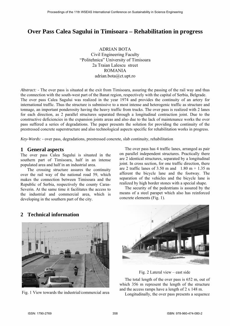
Fig. 1 View towards the industrial/commercial area
The over pass has 4 traffic lanes, arranged as pair on parallel independent structures. Practically there are 2 identical structures, separated by a longitudinal joint. In cross section, for one traffic direction, there are 2 traffic lanes of 3.50 m and 1.80 m + 1.35 m afferent the bicycle lane and the footway. The separation of the vehicles and the bicycle lane is realized by high border stones with a special shape. The security of the pedestrians is assured by the means of a steel parapet which also has reinforced concrete elements (Fig. 1).
Fig. 2 Lateral view – east side The total length of the over pass is 652 m, out of which 356 m represent the length of the structure and the access ramps have a length of 2 x 148 m. Longitudinally, the over pass presents a sequence
Proceedings of the 11th WSEAS International Conference on Sustainability in Science Engineering
ISSN: 1790-2769 358 ISBN: 978-960-474-080-2
of simply supported spans, which, depending on the construction material and the value of the span, can be grouped in three areas: access to Timisoara, constituted of 8 spans of 21 m, central span with L = 41 m and access to Resita with 7 spans of 21 m (Fig. 2). The access areas are realized as isostatic bridge decks with 4 precast prestressed concrete girders. The reinforced concrete slab is poured between the upper flanges of the girders. The steel bearing blocks, a dead abutment and a movable one, are placed in pair on each pile. The fixed bearing is located at the extremity towards the abutment of this specific area. The central span, which realizes the crossing of the rail way, is executed as a composite steel-concrete box girder. The bridge deck bears on steel bearing blocks. The technical documents put in readiness by the City Hall of Timisoara, show that the structure was initially dimensioned back in the 70’s, according to the Romanian standards, for the loading class E, meaning convoys of A30 (trucks of 300 kN) and V80 (special vehicles of 800 kN), fact that makes it compatible, regarding the bearing capacity, with the nowadays traffic and the one in perspective. 3 Actual structure status The carriage way shows numerous degradations, extended on considerable areas, which are more important during the winter time, even if the alternance of the positive and negative temperatures does not point out a significant difference. Due to this, it looses its continuity, the sealing role being thus diminished and the comfort for the users being not assured anymore.
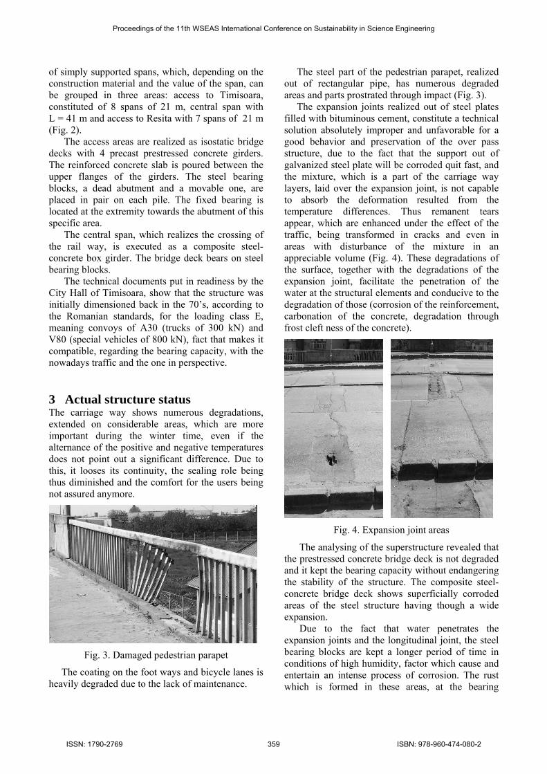
Fig. 3. Damaged pedestrian parapet
The coating on the foot ways and bicycle lanes is heavily degraded due to the lack of maintenance.
The steel part of the pedestrian parapet, realized out of rectangular pipe, has numerous degraded areas and parts prostrated through impact (Fig. 3). The expansion joints realized out of steel plates filled with bituminous cement, constitute a technical solution absolutely improper and unfavorable for a good behavior and preservation of the over pass structure, due to the fact that the support out of galvanized steel plate will be corroded quit fast, and the mixture, which is a part of the carriage way layers, laid over the expansion joint, is not capable to absorb the deformation resulted from the temperature differences. Thus remanent tears appear, which are enhanced under the effect of the traffic, being transformed in cracks and even in areas with disturbance of the mixture in an appreciable volume (Fig. 4). These degradations of the surface, together with the degradations of the expansion joint, facilitate the penetration of the water at the structural elements and conducive to the degradation of those (corrosion of the reinforcement, carbonation of the concrete, degradation through frost cleft ness of the concrete).
Fig. 4. Expansion joint areas
The analysing of the superstructure revealed that the prestressed concrete bridge deck is not degraded and it kept the bearing capacity without endangering the stability of the structure. The composite steel-concrete bridge deck shows superficially corroded areas of the steel structure having though a wide expansion. Due to the fact that water penetrates the expansion joints and the longitudinal joint, the steel bearing blocks are kept a longer period of time in conditions of high humidity, factor which cause and entertain an intense process of corrosion. The rust which is formed in these areas, at the bearing
Proceedings of the 11th WSEAS International Conference on Sustainability in Science Engineering
ISSN: 1790-2769 359 ISBN: 978-960-474-080-2

systems, leads to the diminishing of the mobility of the bearing blocks (Fig. 5 and 6).
Fig. 5. Fixed bearing
Fig. 6. Movable bearing
Thus appears the inconvenience in traffic, but also an enhancement of the dynamic effect when vehicles pass over.
Fig. 7. Degradations at the girder of the pier
Fig. 8. Degradations at the column of the pier
The most important degradations mentioned at the
substructure exist due to the water penetration through the expansion joint covering devices, which are heavily damaged. These damages, materialized through corroded reinforcement and exfoliated concrete, are localized on the bearing bench at the abutments but also at the piers expending on the girders of the piers (Fig. 7). Degradations can also be seen at the covering concrete of the circular columns of the piers (Fig. 8). 4 Rehabilitation solutions Considering the massive degradations of the structure in correlation with the causes which have produced them, specific mending solutions have been foreseen (Fig. 9).
Fig. 9. Designed 4 lanes cross section
In order to maintain the traffic on this sector of the national road, the works will develop on one of the longitudinal structures blocking thus only the traffic lanes afferent to the same traffic direction. The same procedure is applied ulterior also for the structure remained under traffic during the first stage of the works. The rehabilitation works differ from the superstructure to the substructure. 4.1 Superstructure In order to stop the degradation process of the joint areas and to seal them, the continuity of the structure regarding the plate was designed. This means, on one hand, keeping the girders as simply supported elements without changing the distribution of the efforts and, on the other hand, the elimination of the joints between the prestressed concrete bridge decks only by realizing a continuous reinforced concrete slab. As a consequence the entire superstructure of the over pass, for each traffic direction, is divided in three sectors. Only 4 expansion joints are kept, in order to separate these: access to Timisoara with 8 spans out of prestressed concrete, the span over the rail way and access to Resita with 7 spans out of prestressed concrete.
Proceedings of the 11th WSEAS International Conference on Sustainability in Science Engineering
ISSN: 1790-2769 360 ISBN: 978-960-474-080-2

In order to obtain these, certain steps have to be followed:
the layers of the carriage way will be demolished, and also from the foot ways and the bicycle lane;
the foundation needed to mount the provisory system for sustaining the superstructure during the rebuilding of the bearing system; the altitude of the foundation will be under the level of the terrain so it will be covered with earth and reused for the ulterior replacement of the bearing system;
the system for the temporary sustaining of the superstructure, made of sectors of steel tube, designed modular, in such way to have a minimum number of elements and to be reused as often as possible, is mounted considering the variable height of the piers. The intervention is done simultaneously at 4 spans (Fig. 10);
Fig. 10. Temporary sustaining system
at each span first the extremity having movable bearings is lifted (steel rolls) and the bearing areas are rebuild considering the requests of mounting new neoprene bearing blocks; the height of the bearing blocks is adjusted regarding the needs of movement of the specific span in accordance with the temperature variations and its emplacement in the assembly of the structure;
after the emplacement of the bridge deck on the new bearing blocks, the process of lifting respectively rebuilding of the bearing area and mounting adequate bearing blocks is repeated;
after placing all girders on the new bearing blocks (the procedure is not to be applied for the span over the rail way, where the existent bearing blocks are kept), the continuity of the slab over the bearing areas is realized; this area is realized as a double abutment hinge with adequate reinforcement and diminished section in the articulation area being though sufficient
for absorbing the efforts from the compression, which appear from the movement conditions of the bridge deck under the influence of the temperature variations (Fig. 11).
Fig. 11. Continuity of the concrete slab
At the span, which assures the passing over the rail way and which is build in a composite steel- concrete solution, the following works will be done: the maintenance of the steel bearing; cleaning of the intrados of the concrete slab and
of the corroded reinforcement; anticorrosive treatment of the reinforcement and
rebuilding of the covering concrete layer by using epoxy-mortar;
whole cleaning of the steel structure at the interior and exterior;
anticorrosive protection in an adequate multilayer system, as well for the steel structure as also for the concrete slab.
The next working stage means the laying of the waterproofing and of the asphalt carriage way, mounting of separating border stones with specific geometry and steel parapet between the carriage way and the bicycle lane, rebuilding of the foot way in a multi-layer epoxy-polyurethane system with quartz sand respectively replacing of the pedestrian parapet. 4.2 Substructure The works at the substructure are divided in two categories, namely construction works and consolidation works. The construction works mean the modifying of the bearing system of the prestressed concrete girders and namely the replacing of the steel bearings with neopren bearings, works described earlier. The consolidation works aim to bring the substructure at the initial bearing capacity and to assure its good behaviour considering the perspective loads. In order to achieve this, several stages have to be passed:
the degraded concrete, due to the frost-defrost process, is being removed through blasting;
Proceedings of the 11th WSEAS International Conference on Sustainability in Science Engineering
ISSN: 1790-2769 361 ISBN: 978-960-474-080-2

the same procedure is used also for the cleaning of the corroded reinforcement;
the protection concrete layer is rebuild by using epoxy mortar;
if necessary the reinforcement will be completed; the piers will be consolidated by using carbon
fibers; finally, the surface of the entire structure will be
protected with a multilayer system having a proper color.
5 Conclusions Fig. 12. Temporary fundation as steel-concrete
block The solution chosen for the rehabilitation of the over pass Calea Sagului from Timisoara, has reached the following objectives:
the continuity of the slab allows the reduction of the expansion joints from 17 pieces to 4 pieces with a movement capacity of ±50 mm;
the comfort for the users is substantially improved, due to the fact that the major dislevelments from the expansion joint areas are reduced;
the sealing of the areas near the expansion joints is achieved and implicit proper bearing conditions are provided;
the bearing capacity of the substructure is assured in relation to the loadings from the actual traffic and the one in perspective;
the amelioration of the functionality of the over pass is achieved;
the aesthetic aspect of the entire structure is also improved.
At the end of 2008 the rehabilitation works at the Calea Sagului over pass have started. Over the winter time the works were interrupted, being resumed in March 2009. Up to this moment the provisory sustaining systems of the girders for the first 4 spans (afferent the abutment Timisoara on the direction towards the city) were mounted. These systems consist of the temporary and mobile fundation as steel-concrete blocks (Fig. 12) and of the modular steel tube systems (Fig. 13).
Fig. 13. Modular steel tube system References: *** 2001. Consolidare pasaj Calea Şagului DN
59 km 5+000 - 6+600 – PT, SC APECC SRL Timisoara-RO, Contr. 324/2001.
At the moment of the conference, the lifting operations of the superstructure and also the replacing of the bearings are in progress *** 2003. Consolidare pasaj Calea Şagului DN
59 km 5+000 - 6+600 – Work drawings, SC APECC SRL Timisoara-RO, Contr. 324/2001.
*** 2007. Consolidare pasaj Calea Şagului DN 59 km 5+000 - 6+600 – Technical assistance, SC APECC SRL Timisoara-RO, Contr. 418/2007.
Proceedings of the 11th WSEAS International Conference on Sustainability in Science Engineering
ISSN: 1790-2769 362 ISBN: 978-960-474-080-2