Embed Size (px)
Citation preview

INSTRUCTION MANUAL FOR
OVERCURRENT PROTECTION SYSTEM BE1-851
Publication: 9289900990 Revision: M 02/08 www .
Elec
tricalP
artM
anua
ls . c
om

www . El
ectric
alPar
tMan
uals
. com

9289900990 Rev M BE1-851 Introduction i
INTRODUCTION This instruction manual provides information about the operation and installation of the BE1-851 Overcurrent Protection System. To accomplish this, the following information is provided:
• General information, specifications, and a Quick Start guide. • Functional description and setting parameters for the input/output functions, protection and control
functions, metering functions, and reporting and alarm functions. • BESTlogic programmable logic design and programming. • Documentation of the preprogrammed logic schemes and application tips. • Description of security and user interface setup including ASCII communication and the human-
machine interface (HMI). • Installation procedures, dimension drawings, and connection diagrams. • Description of the front panel HMI and the ASCII command interface with write access security
procedures. • A summary of setting, metering, reporting, control, and miscellaneous commands. • Testing and maintenance procedures. • Description of BESTCOMS graphical user interface (GUI). • Appendices containing time overcurrent characteristic curves, an ASCII command-HMI cross
reference, and terminal communication. Optional instruction manuals for the BE1-851 include: • Distributed Network Protocol (DNP) 3.0 (9289900995) • Modbus™ (9289900992).
WARNING! To avoid personal injury or equipment damage, only qualified personnel should perform the procedures in this manual.
NOTE Be sure that the relay is hard-wired to earth ground with no smaller than 12 AWG copper wire attached to the ground terminal on the rear of the unit case. When the relay is configured in a system with other devices, it is recommended to use a separate lead to the ground bus from each unit.
CAUTION Versions of BESTCOMS with version numbers below 1.31.00 are incompatible with newer versions of BE1-851 firmware. If your relay contains version 2.42 firmware or higher (most relays made after August 1999), you MUST upgrade to BESTCOMS version 1.31.00 or higher (version 2.00.00 and higher recommended) before connecting to the relay. Failure to upgrade BESTCOMS prior to connections will result in database corruption of all stored data in earlier versions of BESTCOMS.
www . El
ectric
alPar
tMan
uals
. com

ii BE1-851 Introduction 9289900990 Rev M
First Printing: March 1997
Printed in USA
© 2008 Basler Electric, Highland Illinois 62249 USA
All Rights Reserved
February 2008
It is not the intention of this manual to cover all details and variations in equipment, nor does this manual provide data for every possible contingency regarding installation or operation. The availability and design of all features and options are subject to modification without notice. Should further information be required, contact Basler Electric.
BASLER ELECTRIC ROUTE 143, BOX 269
HIGHLAND IL 62249 USA http://www.basler.com, [email protected]
PHONE +1 618.654.2341 FAX +1 618.654.2351
CONFIDENTIAL INFORMATION of Basler Electric, Highland Illinois, USA. It is loaned for confidential use, subject to return on request, and with the mutual understanding that it will not be used in any manner detrimental to the interest of Basler Electric.
www . El
ectric
alPar
tMan
uals
. com

9289900990 Rev M BE1-851 Introduction iii
REVISION HISTORY
The following information provides a historical summary of the changes made to the BE1-851 hardware, firmware, and software. The corresponding revisions made to this instruction manual (9289900990) are also summarized. Revisions are listed in reverse chronological order.
BESTCOMS Software Version and Date Change
2.05.02, 02/08 • Added “V” and “W” to Option 1 in Style Chart Drawing. (“G” version.) • Added support for relays with “V” or “W” chosen for option 1. (“G”
version.) 2.05.01, 03/07 • Enhanced Settings Compare feature. 2.05.00, 03/06 • Added “E”, “G”, and “R” to Case options in Style Chart Drawing.
• Added Settings Compare feature. • Improved Printer Setup feature. • Improved View/Download Relay Fault Files screen. • Added enable/disable feature for Automatic Output of ASCII Fault
Reports to Communication tab on General Operation screen. (“H” version.)
2.04.00, 06/05 • Added enable/disable feature for Automatic Output of ASCII Fault Reports to Communication tab on General Operation screen. (“G” version.)
2.03.00, 11/04 • Updated 62/162 Logic Timers to support up to 9,999 seconds. • Re-arranged the Global Security tab in the General Operation screen. • Updated the Input Labels and Virtual Switch Labels along with
printouts. • An opened Settings File is now added to the Recent Files List. • BESTCOMS now works with USB to RS-232 and Ethernet to RS-232
converters. 2.02.00, 06/03 • Improved printing. 2.01.01, 10/02 • Added an error message when virtual test switches, inputs, and
outputs are left blank. 2.00.00, 11/01 • Initial release of 32-bit version. 1.32.01, 03/00 • Added support for version 3 hardware. 1.01.01, 10/97 • Initial release of 16-bit version.
Application Firmware
Version and Date Change 4.49.00, 02/08 3.49.00, 02/08
• Added “V” and “W” to Option 1 of style number. When option 1 is “V” or “W”, two additional logic timers (262 and 362) are available and the 243 and 343 virtual switches are removed. (“G” version.)
• Added alternate DST (Daylight Saving Time) settings in Section 6, Reporting and Alarm Functions. (“G” version.)
4.48.03, 09/06 • Added SG-DATADUMP command to cause the fault report information to be automatically output to COM1. (“H” version”.)
• Enhanced the HMI to show Fault Report data on Screen 4.1.1. (“H” version.)
• Added style number and firmware version to fault reports. • Minor firmware improvements.
www . El
ectric
alPar
tMan
uals
. com

iv BE1-851 Introduction 9289900990 Rev M
Application Firmware Version and Date Change
4.48.01, 06/05 3.48.01, 06/05 2.48.01, 06/05
• Added SG-DATADUMP command to cause the fault report information to be automatically output to COM1. (“G” version.)
• Enhanced the HMI to show Fault Report data on Screen 4.1.1. (“G” version.)
4.46.02, 09/04 3.46.02, 09/04 2.45.02, 09/04
• Added DNP commands. (4.46.02 & 3.46.02 only.) • Improved performance of the 62 function to support time delays up to
9,999 seconds. • Enhanced performance of the 79 function.
3.45.00, 06/03 • Enabled target reset through Modbus. 3.43.09, 03/03 • Added the capability of changing Modbus Password Security with the
ASCII command. • Enhanced the 3rd parameter {C} for the SP-CURVE command (user
programmable time curve). • Insured year change update with IRIG connected, under all
conditions. 3.43.07, 03/02 • Enhanced fault data capture.
• Improved operation of the front panel Reset key with resettable data. • Improved the accuracy of oscillographic waveform amplitude. • Enhanced SA-BKR mode; more than one setting can be entered. • Improved the display of the reclose cycle. • Improved settings change capability. • Automatically display the Target screen on the HMI after fault. • Added operation of the 43 switches on the HMI scroll list.
3.43.06, 02/02 2.43.06, 02/02
• Improved accuracy of oscillographic waveform amplitude measurement.
• Added functionality of DNP Version 2 with BESTCOMS. 3.43.05, 02/02 2.43.05, 02/02
• Improved modes of operation for SA-BKR command used to read or set alarm settings.
• Changed alarm functionality so that an alarm threshold value of zero will disable the alarm.
• Mode settings entered with multiple digits now return an error. Only one digit may be entered for a mode setting.
• Improved the BE1-851 to prevent “lockup” from issuing too many settings changes at one time.
3.43.00, 02/00 • Updated the GF-VER and RG-VER commands to report Model Number BE1-851G for style type Gxxxxx and Model Number BE1-851 for style type Hxxxxx.
• Updated to support sensing type G (Florida Power Light) which replaces 51Q with 151N, 50TQ with 250TN, and 150TQ with 350TN. (This hex file version only works with style type Hxxxxx.)
3.42.01, 11/99 • Added DNP 3.0, Level 2 compliance. Requires Version 3.xx hardware.
• Added support for Version 3 hardware with additional memory. • Oscillographic recording is as follows:
Feature Version 3.xx Number of Oscillographic Records 16 Length of Oscillographic Records 15 cycles each Sample Resolution 24 samples/cycle
www . El
ectric
alPar
tMan
uals
. com

9289900990 Rev M BE1-851 Introduction v
Application Firmware Version and Date Change
• Improved target reporting function. • The trip LED only latches when there are targets to be displayed on
the HMI. The “pickup” condition, indicated by the Trip LED flashing, is now a higher priority than latching to indicate that targets are being displayed on the HMI.
• Improved HMI Target screen format. Screen now reports targets in a text format. Additional information such as fault current magnitudes and time and date of the fault were moved to a lower menu branch so that the targets are all that is displayed unless the user wants more detail.
• Added functionality to reset targets using a programmable logic expression in addition to the HMI Reset key and the ASCII command interface using the RG-TARG=0 command. This allows targets to be reset by pulsing a contact sensing input.
• Improved COMTRADE oscillography recording function by adding *.hdr (header) file to the COMTRADE mandatory files *.cfg and *.dat. The new *.hdr file is a text file that contains the Fault Summary Report and the appropriate settings that were active at the time of the event.
• Added all BESTlogic programmable logic bit status to oscillography files as digital channels. Logic variables with user programmable names are reported using the programmable name instead of the generic name.
• Improved Sequence of Events Recording function by increasing the number of events recorded from 127 to 255.
• Added additional reporting options. It is now possible to retrieve SER data for Alarm Events only, RS-ALM; Input/Output Events only, RS-IO; and Logic Variable Events only, RS-LGC.
• Improved BESTlogic functionality. • Eliminated the setting required to specify which logic scheme is
active. Now the user’s logic settings are always active. This setting used to be made from the ASCII command interface using the SP-LOGIC command.
• Changed default logic settings from everything disabled to a simple logic scheme with 50 and 51 protection enabled.
• Added Logic = None Alarm to alert the user if the relay has no programmable logic settings.
• Added Changes Lost Alarm to alert the user if the user has been editing settings and the access timer times out without an Exit; Save Setting? Yes command being entered.
• Added functionality to reset alarms using a programmable logic expression in addition to the HMI Reset key and the ASCII command interface using the RA=0 command. Allows alarms to be reset by pulsing a contact sensing input.
• Added new alarm logic variable to BESTlogic. ALMLGC can be used to link programmable alarm functions to your logic scheme without activating an Alarm LED on the HMI.
• Removed the relay trouble alarm logic variable, ALMREL, from programmable logic. Since programmable logic is disabled when this condition is TRUE, it was a superfluous variable. For rearward compatibility, the relay will not give an alarm if this logic variable is used in a logic expression.
• Improved the virtual switches 43 and 101 functions by adding
www . El
ectric
alPar
tMan
uals
. com

vi BE1-851 Introduction 9289900990 Rev M
Application Firmware Version and Date Change
functionality to set four modes of operation for the 43 Virtual Selector Switch and adding functionality to set two modes of operation for the 101 Virtual Breaker Control Switch.
• Change the preprogrammed logic schemes to include the new virtual switch functionality.
• Improved the 62 timer functions by adding Mode 5, Integrating Timer and Mode 6, Latch. Added targeting to 62 timer functions.
• Added functionality to allow the breaker monitoring duty accumulation to be blocked by a logic expression.
• Added automatic daylight saving time adjustment to the real time clock.
• Added functionality to the automatic setting group selection function to allow it to monitor protective functions in addition to the 51P function.
• Setting groups can be changed based on unbalanced currents by monitoring the 51N and 51Q functions.
• Setting groups can be changed during the reclosing sequence by monitoring the 79 shot counter.
• Changed the default settings for programmable variable names. Defaults are now all set to generic variable names with state names of TRUE or FALSE.
• Re-ordered the output of the S command to match the order of settings as listed in the instruction manual, Appendix C.
2.41.00, 06/99 • Added Modbus™ full write functionality. • Changed version format from x.xx to x.xx.xx. • Added Transducer Network Lite Protocol (TNP Lite). • Improved trip circuit monitor to allow use with ac trip voltage.
2.37, 11/98 • Increased the range of breaker duty I or I2 accumulation from 2.17e7 to 4.2e7.
2.36, 09/98 • Added Distributed Network Protocol (DNP) 3.0 with limited read and control functions.
2.31, 02/98 • Increase the range of the programmable 51 curve, A coefficient, from 0 - 100 to 0 - 600.
www . El
ectric
alPar
tMan
uals
. com

9289900990 Rev M BE1-851 Introduction vii
Application Firmware Version and Date Change
2.27, 01/98 • Improved 62 timer performance. • Changed minimum breaker failure time from 100 ms to 50 ms. • Added functionality to enable or disable targets for each protective
function. • Added functionality to allow HMI Alarm Reset pushbutton to be used
as a logic variable (RSTKEY). • Improved fault recording functions as follows:
o Phase, neutral, and negative-sequence currents are recorded one cycle after the TRIP trigger logic becomes TRUE.
o Added programmable alarm for Fault Record Time Out and changed the error readout to show N/A for this condition with BREAKER OPERATE TIME and FAULT CLEARING TIME.
o Change the RF-TRIP to show RF=TRIG instead of SERIAL for EVENT TYPE and FAULT TRIGGER.
o Second oscillographic record triggering point was changed from when the TRIP trigger logic became TRUE, to when both PU and LOGIC trigger logic became FALSE.
o Second oscillographic record was changed to record without a gap between the first and second records during specific conditions.
2.15, 05/97 • Initial release
Hardware
Version and Date Change Version 4, 05/03 • Added real time clock chip, 8-hour capacitor ride-through for real time
clock, optional battery backup for real time clock and jumper-selectable voltage rating for the contact sensing inputs.
Version 3, 11/99 • Label placed on the front panel stating, “WARNING to BESTCOMS USERS: When using BESTCOMS software you must upgrade to VER 1.31.00 or higher prior to communicating with this unit. Failure to do so will result in corruption of the settings database.”
• Contact sensing input circuits re-designed to turn on at specific voltage ranges. These ranges are specified in the instruction manual. Contact sensing circuits may turn on at voltages outside of these specified ranges with previous versions of the relay.
Version 2, 05/97 • Initial release
Manual
Revision and Date Change M, 02/08 • Added “V” and “W” to Option 1 in Style Chart. These options add 262
and 362 timers and remove 243 and 343 virtual switches. Updated manual with information on these changes.
• Added Settings Compare to Section 6, Reporting and Alarm Functions.
• Added Alternate DST (Daylight Saving Time) settings/commands to Sections 6, 11 and Appendix B.
www . El
ectric
alPar
tMan
uals
. com

viii BE1-851 Introduction 9289900990 Rev M
Manual Revision and Date Change
L, 12/06 • Updated front panel drawings throughout manual. • Added adapter bracket drawings, Figures 12-11 and 12-12. • Added CE statement in Section 1, General Information. • Updated output contact ratings in Section 1. • Added style number and firmware version to fault reports.
K, 03/06 • Removed Relay Settings Records Appendix. • Added examples to ASCII commands in Section 11. • Added GOST-R Certification to Section 1. • Added “E”, “G”, and “R” to Case options in style number. (N.O. Alarm
Output contacts.) J, 06/05 • Updated Figure 10-5 to show new Fault screens for “G” style relays.
• Added “Data Dump” to rear RS-232 port for “G” style relays. • Enhanced 62/162 function to support up to 9,999 seconds. • Updated BESTCOMS screen images.
H, 09/03 • Updated the discussion on Current Measurement Functions on page 3-1 and 3-2.
• In Table 4-11, changed “Disables” to “Enables” for the Initiate setting. • Did a general update of Section 6, Reporting and Alarm Functions
including an update of Table 6-10, a rewrite of Oscillographic Records, pages 6-24 and 6-25, and correction of screen or table references.
G, 06/02 • Revised instruction manual to focus on the use of BESTCOMS for setting the relay.
• Equation errors in Appendix A were corrected. F, 03/00 • Added paragraphs on Breaker Failure in Section 4.
• Updated the manual to reflect the sensing input type Gxxxxx units. • Converted the entire manual to a single volume.
E, 12/99 • Changed the manual to a two-volume set. • Updated the manual to reflect extended oscillographic reporting. • Added Modes 5 and 6 to 62/162 timer functionality. • Updated logic scheme tables and diagrams to reflect new default
settings. • Changed all of the default settings. • Removed the SP logic serial command but added the SA-LGC and
RA-LGC commands. • Changed the sequence of events recorder maximum number of
events from 127 to 255 in all references.
www . El
ectric
alPar
tMan
uals
. com

9289900990 Rev M BE1-851 Introduction ix
Manual Revision and Date Change
D, 03/98 • Manual was revised to reflect improvements in embedded software versions 2.29, 2.30, 2.31, and 2.32.
• SG-TARG and RSTKEY commands were added. • Replaced the text after and including Current Demand Reporting of
Section 3 with new alarms and outputs information. • Changed the BF Timer range in Section 1 from 100 - 999 ms to 50 -
999 ms. • In Table 1-3 the “A” parameter of curve “P” was changed from 0 - 100
to 0 - 600. • Added a new style chart, Figure 1-4, with S1 cover and DNP 3.0
options. • Curve names in Tables 1-4 through 1-20 were changed to match the
names in Figures 1-5 through 1-20. • Added a missing connection in the logic diagram, Figure 5-1. • Added UL and CSA logos to the style label shown on the front cover
graphics. —, 03/97 • Initial release
www . El
ectric
alPar
tMan
uals
. com

x BE1-851 Introduction 9289900990 Rev M
This page intentionally left blank.
www . El
ectric
alPar
tMan
uals
. com
9289900990 Rev M BE1-851 Introduction xi
CONTENTS
SECTION 1 • GENERAL INFORMATION ................................................................................................ 1-1
SECTION 2 • QUICK START.................................................................................................................... 2-1
SECTION 3 • INPUT AND OUTPUT FUNCTIONS................................................................................... 3-1
SECTION 4 • PROTECTION AND CONTROL......................................................................................... 4-1
SECTION 5 • METERING......................................................................................................................... 5-1
SECTION 6 • REPORTING AND ALARM FUNCTIONS .......................................................................... 6-1
SECTION 7 • BESTlogic PROGRAMMABLE LOGIC............................................................................... 7-1
SECTION 8 • APPLICATION .................................................................................................................... 8-1
SECTION 9 • SECURITY.......................................................................................................................... 9-1
SECTION 10 • HUMAN-MACHINE INTERFACE ................................................................................... 10-1
SECTION 11 • ASCII COMMAND INTERFACE..................................................................................... 11-1
SECTION 12 • INSTALLATION .............................................................................................................. 12-1
SECTION 13 • TESTING AND MAINTENANCE .................................................................................... 13-1
SECTION 14 • BESTCOMS SOFTWARE .............................................................................................. 14-1
APPENDIX A • TIME OVERCURRENT CHARACTERISTIC CURVES................................................... A-1
APPENDIX B • COMMAND CROSS-REFERENCE................................................................................. B-1
APPENDIX C • TERMINAL COMMUNICATION.......................................................................................C-1
www . El
ectric
alPar
tMan
uals
. com

xii BE1-851 Introduction 9289900990 Rev M
This page intentionally left blank.
www . El
ectric
alPar
tMan
uals
. com
9289900990 Rev M BE1-851 General Information i
SECTION 1 • GENERAL INFORMATION TABLE OF CONTENTS
SECTION 1 • GENERAL INFORMATION ................................................................................................ 1-1
GENERAL.............................................................................................................................................. 1-1 FEATURES............................................................................................................................................ 1-1
Input and Output Functions ................................................................................................................ 1-1 Protection and Control Functions....................................................................................................... 1-2 Metering.............................................................................................................................................. 1-3 Reporting and Alarm Functions.......................................................................................................... 1-3 BESTlogic Programmable Logic ........................................................................................................ 1-4 Security............................................................................................................................................... 1-4 Human-Machine Interface .................................................................................................................. 1-4 Communication................................................................................................................................... 1-4 BESTCOMS Software ........................................................................................................................ 1-5
PRIMARY APPLICATIONS ................................................................................................................... 1-5 MODEL AND SYLE NUMBER DESCRIPTION..................................................................................... 1-6
General............................................................................................................................................... 1-6 Sample Style Number ........................................................................................................................ 1-6
OPERATIONAL SPECIFICATIONS ...................................................................................................... 1-7 Metered Current Values and Accuracy .............................................................................................. 1-7 Calculated Values and Accuracy ....................................................................................................... 1-7 Real Time Clock ................................................................................................................................. 1-7 Time Overcurrent Functions............................................................................................................... 1-7 Time Current Characteristic Curves................................................................................................... 1-7 Instantaneous Overcurrent Functions ................................................................................................ 1-8 Reclosing Timers (79) ........................................................................................................................ 1-8 Breaker Fail Timer (BF)...................................................................................................................... 1-9 General Purpose Timers (62, 162, 262∗, 362∗) ................................................................................. 1-9 Automatic Setting Group Characteristics ........................................................................................... 1-9
GENERAL SPECIFICATIONS............................................................................................................... 1-9 AC Current Inputs............................................................................................................................... 1-9 Analog to Digital Converter ................................................................................................................ 1-9 Power Supply ................................................................................................................................... 1-10 Output Contacts ............................................................................................................................... 1-10 Control Inputs ................................................................................................................................... 1-10 IRIG .................................................................................................................................................. 1-10 Contact Inputs Recognition Time ..................................................................................................... 1-11 Communication Ports ....................................................................................................................... 1-11 Display.............................................................................................................................................. 1-11 Isolation ............................................................................................................................................ 1-11 Surge Withstand Capability .............................................................................................................. 1-11 Radio Frequency Interference (RFI) ................................................................................................ 1-11 Electrostatic Discharge (ESD).......................................................................................................... 1-11 Shock................................................................................................................................................ 1-11 Vibration ........................................................................................................................................... 1-12 Environment ..................................................................................................................................... 1-12 CE Qualified ..................................................................................................................................... 1-12 UL Recognition................................................................................................................................. 1-12 C.S.A. Certification ........................................................................................................................... 1-12 GOST-R Certification ....................................................................................................................... 1-12 DNP Certification.............................................................................................................................. 1-12 Physical ............................................................................................................................................ 1-12
Figures Figure 1-1. Style Number Identification Chart ........................................................................................... 1-6
www . El
ectric
alPar
tMan
uals
. com

ii BE1-851 General Information 9289900990 Rev M
Tables Table 1-1. Burden.................................................................................................................................... 1-10
www . El
ectric
alPar
tMan
uals
. com

9289900990 Rev M BE1-851 General Information 1-1
SECTION 1 • GENERAL INFORMATION GENERAL The BE1-851 Overcurrent Protection System is an economical, microprocessor based, multifunction system. It is available in S1 (Basler/GE style), H1 (half-rack), and F1 (Westinghouse FT-11 size) configurations. BE1-851 features include:
• Time & Instantaneous Overcurrent Protection • Control • Automatic Reclosing • Breaker Failure Protection
• Breaker Monitoring • Metering Functions • Communication
BE1-851 relays have four programmable contact sensing inputs, five programmable outputs, and one alarm output. Outputs can be assigned to perform protection, control, or indicator operations through logical programming. For example, protection functions could be programmed to cause a protective trip. Control functions could be programmed to cause a manual trip, manual close, or automatic reclose. Indicators could be configured to annunciate relay failure, a settings group change, and others. Protection scheme designers may select from a number of pre-programmed logic schemes that perform the most common protection and control requirements. Alternately, a custom scheme can be created using BESTlogic. A simplified “How To Get Started” procedure for BE1-851 users is provided in Section 2, Quick Start.
FEATURES The BE1-851 relay includes many features for the protection, monitoring, and control of power system equipment. These features include protection and control functions, metering functions, and reporting and alarm functions. A highly flexible programmable logic system called BESTlogic allows the user to apply the available functions with complete flexibility and customize the system to meet the requirements of the protected power system. Programmable I/O, extensive communication features, and an advanced human-machine interface (HMI) provide easy access to the features provided. The following information summarizes the capabilities of this multifunction device. Each feature along with how to set it up and how to use its outputs is described in complete detail in the later section of this manual.
Input and Output Functions Input functions consist of power system measurement and contact sensing inputs. Programmable contact outputs make up the output functions. Input and output functions are described in the following paragraphs.
Power System Measurement Functions BE1-851 relays are designed for operation on both 50 and 60 Hz systems and have four current inputs to measure phase and neutral currents. It is a numerical device that samples the analog current waveforms and uses mathematical algorithms to measure the operating quantities. One of three current measurement algorithms may be individually selected for phase and neutral. Those are:
• Fundamental • Average • Wideband RMS
The fundamental algorithm responds to the fundamental component of the current and rejects the harmonic components. The average algorithm emulates an RC measurement circuit and has a relatively flat response characteristic over a wide frequency range. The wideband RMS algorithm measures all components of the current up to the seventh harmonic. In addition, the relay measures the magnitude of the negative-sequence component of the fundamental phase current quantities. The negative-sequence measurement has by definition a fundamental response characteristic.
www . El
ectric
alPar
tMan
uals
. com

1-2 BE1-851 General Information 9289900990 Rev M
Each current sensing circuit is low burden and isolated. Negative-sequence current magnitudes are derived from the three-phase currents. Neutral current input is available for direct measurement of the current in a transformer neutral, tertiary winding, or flux balancing current transformer.
Contact Sensing Inputs Four programmable contact sensing inputs (IN1, IN2, IN3, and IN4) with programmable signal conditioning provide a binary logic interface to the protection and control system. Each input’s function and labeling is programmable using BESTlogic. A user-meaningful name can be assigned to each input and to each state (energized and de-energized) for use in reporting functions.
Contact Outputs Five programmable general-purpose contact outputs (OUT1, OUT2, OUT3, OUT4, and OUT5) provide a binary logic interface to the protection and control system. One programmable, fail-safe contact output (OUTA) provides an alarm output. Each output’s function and labeling is programmable using BESTlogic. A user-meaningful name can be assigned to each output and to each state (open and closed) for use in reporting functions. Output logic can be overridden to open, close, or pulse each output contact for testing or control purposes. All output contacts are trip rated.
Protection and Control Functions Protection functions consist of overcurrent, breaker reclosing, and breaker failure protection and general-purpose logic timers. Setting groups and virtual control switches make up the control functions. The following paragraphs describe each protection and control function.
Overcurrent Protection Overcurrent protection is provided by six instantaneous overcurrent functions and three time-overcurrent functions. Each instantaneous overcurrent function has a settable time delay. Sensing input type G relays have two phase and four neutral elements. Sensing input type H relays have two phase, two neutral, and two negative-sequence elements. Phase elements include 50TP and 150TP. Neutral elements include 50TN, 150TN, 250TN, and 350TN. Negative-sequence elements include 50TQ and 150TQ. A 51P phase element, 51Q negative-sequence element, and 51N and 151N neutral elements are provided for time overcurrent functions. Sensing input type G relays have one phase and two neutral elements. Sensing input type H units have one phase, one neutral, and one negative-sequence element. Time overcurrent functions employ a dynamic integrating timing algorithm covering a range from pickup to 40 times pickup with selectable instantaneous or integrated reset characteristics. Time overcurrent curves conform to the IEEE C37.112 document and include seven curves similar to Westinghouse/ABB CO curves, five curves similar to GE IAC curves, IEC types A, B, C, and G, a fixed time curve, and a user programmable curve.
Breaker Failure Protection One breaker failure protection block (BF) provides programmable breaker failure protection.
General Purpose Logic Timers Two general-purpose logic timers (62, 162) with six modes of operation are provided. Four general-purpose logic timers (62, 162, 262, 362) are provided when style option 1 is V or W.
Setting Groups Four setting groups allow adaptive relaying to be implemented to optimize BE1-851 settings for various operating conditions. Automatic and external logic can be employed to select the active setting group.
Virtual Control Switches BE1-851 virtual control switches include one virtual breaker control switch and four virtual switches. Trip and close control of a selected breaker can be controlled by the virtual breaker control switch (101). The virtual breaker control switch is accessed locally from the human-machine interface (HMI) or remotely from the communication ports. Additional control is provided by the four virtual switches: 43, 143, 243∗, and 343∗. These virtual switches are accessed locally from the HMI or remotely from the communication ports. Virtual switches can be used to trip and close additional switches or breakers, or enable and disable certain functions. ∗ 243 and 343 are not available when style option 1 is V or W.
www . El
ectric
alPar
tMan
uals
. com

9289900990 Rev M BE1-851 General Information 1-3
Metering Metering is provided for all measured currents, and all derived neutral and negative-sequence currents. One percent meter accuracy is provided down to ten percent of nominal current.
Reporting and Alarm Functions Several reporting and alarm functions provide fault reporting, demand, breaker, and trip circuit monitoring as well as relay diagnostic and firmware information.
Relay Identification Two free-form fields are provided for the user to enter information to identify the relay. These fields are used by many of the reporting functions to identify the relay that the report is from. Examples of relay identification field uses are station name, circuit number, relay system, purchase order, and others.
Clock A real-time clock is included with a capacitor backup and is available with an optional battery backup. Depending upon conditions, capacitor backup maintains timekeeping during an 8 to 24 hour loss of operating power. Battery backup maintains timekeeping when operating power is removed for up to five years or longer. A standard IRIG input is provided for receiving time synchronization signals from a master clock. Automatic daylight saving time compensation can be enabled. Time reporting is settable for 12 or 24-hour format. The date can be formatted as mm/dd/yy or dd/mm/yy.
General Status Reporting The BE1-851 provides extensive general status reporting for monitoring, commissioning, and troubleshooting. Status reports are available from the HMI or communication ports.
Demand Reporting Ampere demand registers monitor phase A, B, C, neutral, and negative-sequence values. The demand interval and demand calculation method are independently settable for phase, neutral, and negative-sequence measurements. Demand reporting records today’s peak, yesterday’s peak, and peak since reset with time stamps for each register.
Breaker Monitoring Breaker statistics are recorded for a single breaker. They include the number of operations, accumulated interrupted I or I2, and breaker time to trip. Each of these conditions can be set to trigger an alarm.
Trip Circuit Monitoring A trip circuit monitor function is provided to monitor the trip circuit of a breaker or lockout relay for loss of voltage (fuse blown) or loss of continuity (trip coil open). The monitoring input is internally connected across OUT1. Additional trip or close circuit monitors can be implemented in BESTlogic using additional inputs, logic timers, and programmable logic alarms.
Fault Reporting Fault reports consist of simple target information, fault summary reports, and detailed oscillography records to enable the user to retrieve information about disturbances in as much detail as is desired. The relay records and reports oscillography data in industry standard IEEE, COMTRADE format to allow using any fault analysis software.
Sequence of Events Recorder A 255-event Sequence of Events Recorder (SER) is provided that records and time stamps all relay inputs and outputs as well as all alarm conditions monitored by the relay. Time stamp resolution is to the nearest quarter-cycle. I/O and alarm reports can be extracted from the records as well as reports of events recorded during the time span associated with a specific fault report.
Alarm Function Extensive self-diagnostics will trigger a fatal relay trouble alarm if any of the relay’s core functions are adversely affected. Fatal relay trouble alarms are not programmable and are dedicated to the alarm output (OUTA) and the front panel Relay Trouble LED. Additional relay trouble alarms and all other alarm functions are programmable for major or minor priority. Programmed alarms are indicated by major and minor alarm LEDs on the front panel. Major and minor alarm points can also be programmed to any
www . El
ectric
alPar
tMan
uals
. com

1-4 BE1-851 General Information 9289900990 Rev M
output contact including OUTA. Over 20 alarm conditions are available to be monitored including user definable logic conditions using BESTlogic. Active alarms can be read and reset from the HMI or from the communication ports. A historical sequence of events report with time stamps lists when each alarm occurred and cleared. These reports are available through the communication ports.
Version Report The version of the embedded software (firmware) is available from the HMI or the communication ports. The unit serial number and style number is also available through the communication ports.
BESTlogic Programmable Logic Each BE1-851 protection and control function is implemented in an independent function block. Every function block is equivalent to its single function, discrete device counterpart so it is immediately familiar to the protection engineer. Each independent function block has all of the inputs and outputs that the discrete component counterpart might have. Programming with BESTlogic is equivalent to choosing the devices required by your protection and control scheme and then drawing schematic diagrams to connect the inputs and outputs to obtain the desired operating logic. Several preprogrammed logic schemes and a set of custom logic settings are provided. A preprogrammed scheme can be activated by merely selecting it. Custom logic settings allow you to tailor the relay functionality to match the needs of your operation’s practices and power system requirements.
Security Security can be defined for three distinct functional access areas: Settings, reports, and control. Each access area can be assigned its own password. A global password provides access to all three functional areas. Each of the four passwords can be unique or multiple access areas can share the same password. As second dimension of security is provided by allowing the user to restrict access for any of the access areas to only specific communication ports. For example, you could set up security to deny access to control commands from the rear RS-232 port that is connected through a modem to a telephone line. Security settings only affect write access. Read access is always available in any area through any port.
Human-Machine Interface Each BE1-851 comes with a front panel display with five LED indicators for Power Supply Status, Relay Trouble Alarm, Minor Alarm, Major Alarm, and Trip. The lighted, liquid crystal display (LCD) allows the relay to replace local indication and control function such as panel metering, alarm annunciation, and control switches. The LCD has automatic priority logic to govern what is being displayed on the screen so that when an operator approaches, the information of most interest is automatically displayed without having to navigate the menu structure. The order of priorities is:
1. Recloser active 2. Targets 3. Alarms 4. Programmable automatic scrolling list
Up to 16 screens can be defined in the programmable, automatic scroll list.
Communication Three independent, isolated communication ports provide access to all functions in the relay. COM0 is a 9-pin female RS-232 port located on the front of the case. COM1 is a 9-pin female RS-232 port located on the back of the case. An ASCII command interface allows easy interaction with the relay by using standard off the shelf communication software. The ASCII command interface is optimized to allow automating of the relay setting process. Settings files can be captured from the relay and edited using any software that supports the *.txt file format. These ASCII test files can then be used to set the relay using the send text file function of your communication software. Modbus™ and other common protocols are optionally available for the RS-485 communication port. A separate instruction manual is available for each available protocol. Consult the product bulletin or the factory for availability of these options and instruction manuals.
www . El
ectric
alPar
tMan
uals
. com

9289900990 Rev M BE1-851 General Information 1-5
BESTCOMS Software BESTCOMS is a Windows® based graphical user interface (GUI) that runs on IBM-compatible computers. The software is used to create settings files for protection, control, operating logic, breaker monitoring, metering, and fault recording functionality. A primary advantage to BESTCOMS is that these setting files may be created while off line (not connected to a unit). This feature gives the engineer flexibility in developing, testing, and replicating the settings before exporting them to a file and transmitting the file to technical personnel in the field. The BESTCOMS GUI also includes the same preprogrammed logic schemes that are contained in the relay. This allows engineers the flexibility of developing setting files using a preprogrammed logic scheme, customizing a preprogrammed logic scheme or building a scheme from scratch. Logic schemes are developed using the GUI Logic Builder. The logic builder uses basic Boolean and/or constructs to develop logic schemes.
PRIMARY APPLICATIONS The BE1-851 Overcurrent Protection System provides complete circuit protection with multiple overcurrent elements and is intended for use in any non-directional overcurrent application. Its unique capabilities make it ideally suited for applications where:
• Low burden is required to extend the linear range of CTs. • One relay provides the flexibility of wide settings ranges, multiple settings groups, and multiple
coordination curves. • A multifunction, multi-phase relay is desired for economical and space saving benefits. A single
BE1-851 provides all of the protection, local and remote indication, metering, and control required on a typical circuit.
• Communication capability and protocol support is desired. • Applications that require specific current response characteristics.
o The fundamental digital signal-processing (DSP) algorithm provides rejection of harmonics and low transient overreach.
o The RMS DSP algorithm provides true wide band RMS measurement. o The average DSP algorithm provides a flat response characteristic over a wide frequency
range. • Bus protection is provided by a high-speed overcurrent-blocking scheme on the transformer bus
mains instead of a bus differential circuit. • The capabilities of intelligent electronic devices (IEDs) are used to decrease relay and equipment
maintenance costs. • Applications where the optional case configurations facilitate retrofit in existing substations. One
electromechanical overcurrent or reclosing relay can be replaced by a BE1-851 relay. The remaining relays can be removed or left in service as backup.
• Applications where the capabilities of a digital multifunction relay are required yet test paddles and/or drawout construction is also required.
www . El
ectric
alPar
tMan
uals
. com
1-6 BE1-851 General Information 9289900990 Rev M
MODEL AND SYLE NUMBER DESCRIPTION
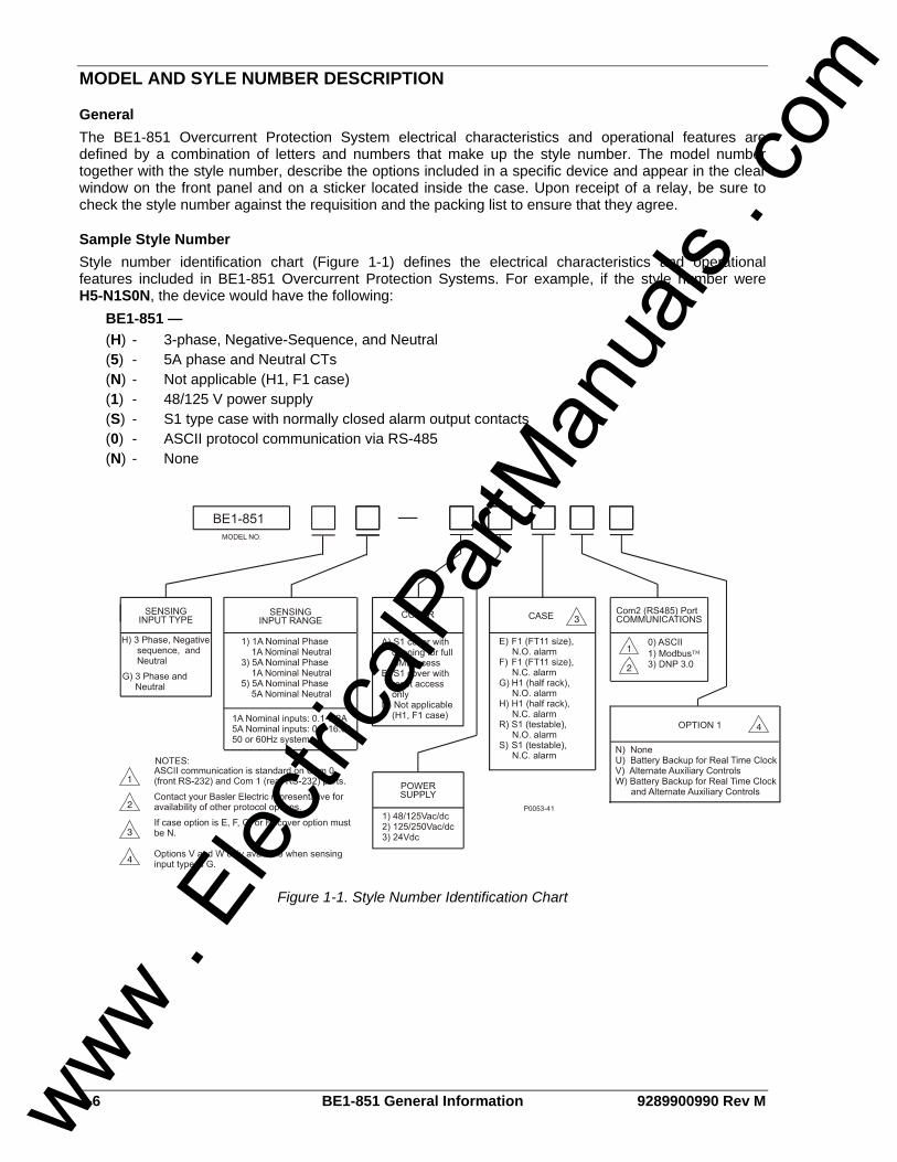
General The BE1-851 Overcurrent Protection System electrical characteristics and operational features are defined by a combination of letters and numbers that make up the style number. The model number together with the style number, describe the options included in a specific device and appear in the clear window on the front panel and on a sticker located inside the case. Upon receipt of a relay, be sure to check the style number against the requisition and the packing list to ensure that they agree.
Sample Style Number Style number identification chart (Figure 1-1) defines the electrical characteristics and operational features included in BE1-851 Overcurrent Protection Systems. For example, if the style number were H5-N1S0N, the device would have the following: BE1-851 —
(H) - 3-phase, Negative-Sequence, and Neutral (5) - 5A phase and Neutral CTs (N) - Not applicable (H1, F1 case) (1) - 48/125 V power supply (S) - S1 type case with normally closed alarm output contacts (0) - ASCII protocol communication via RS-485 (N) - None
Figure 1-1. Style Number Identification Chart
www . El
ectric
alPar
tMan
uals
. com

9289900990 Rev M BE1-851 General Information 1-7
OPERATIONAL SPECIFICATIONS BE1-851 relays have the following features and capabilities:
Metered Current Values and Accuracy Current Range: 0.1 to 1.5 nominal Accuracy (Phase and Neutral): ±1% of reading, ±1 least significant digit at 25°C Accuracy (Negative-Sequence): ±1.5% of reading, ±1 least significant digit at 25°C Temperature Dependence: ≤ ±0.02% per °C
Calculated Values and Accuracy
Demand Range: 0.1 to 1.5 nominal Type: Exponential Accuracy: ±1% of reading ±1 digit at 25°C Interval: 1 to 60 minutes
Real Time Clock Accuracy: 1 second per day at 25°C (free running) or ±2 milliseconds (with IRIG synchronization) Resolution: 1 millisecond Date and Time Setting Provisions: Front panel, communications port, and IRIG. Leap year correction provided. Clock Power Supply Holdup Capacitor: 8 to 24 hours, depending on conditions Clock Power Supply Holdup Battery: Greater than 5 years Backup Battery (Optional): Lithium battery 3.6 Vdc, 0.95 AH,
Basler Electric p/n: 9318700012, or Applied Power p/n: BM551902
Time Overcurrent Functions
Current Pickup, Phase & Neutral (51P, 51N, 151N) Pickup Accuracy 5 Ampere CT: ±2% or ±50 mA 1 Ampere CT: ±2% or ±10 mA Dropout/pickup ratio: 95%
Current Pickup, Negative-Sequence (51Q) Pickup Accuracy 5 Ampere CT: ±3% or ±75 mA 1 Ampere CT: ±3% or ±15 mA Dropout/pickup ratio: 90%
Current Input All 51 Functions 5 Ampere CT Range: 0.50 to 16.0 A Increments: 0.01 from 0.50 to 9.99 A 0.1 from 10.0 to 16.0 A 1 Ampere CT Range: 0.10 to 3.20 A Increments: 0.01 A
Time Current Characteristic Curves Timing Accuracy (All 51 Functions): Within ±5% or ±1½ cycles whichever is greater for
time dial settings greater than 0.1 and multiples of 2 to 40 times the pickup setting but not over 150 A for 5 A CT units or 30 A for 1 A CT units.
www . El
ectric
alPar
tMan
uals
. com

1-8 BE1-851 General Information 9289900990 Rev M
Instantaneous Overcurrent Functions
Current Pickup Accuracy Phase & Neutral (50TP, 50TN, 150TP, 150TN, 250TN, 350TN) 5 Ampere CT: ±2% or ±50 mA 1 Ampere CT: ±2% or ±10 mA Dropout/pickup ratio: 95% or higher Negative-Sequence (50TQ, 150TQ) 5 Ampere CT: ±3% or ±75 mA 1 Ampere CT: ±3% or ±15 mA Dropout/pickup ratio: 95% or higher
Current Pickup Ranges (50T, 150T) 5 Ampere CT Range: 0.5 to 150.0 A Increments: 0.01 from 0.50 to 9.99 A 0.1 from 10.0 to 99.99 A 1.0 from 100 to 150 A 1 Ampere CT Range: 0.1 to 30.0 A Increments: 0.01 from 0.01 to 9.99 A 0.1 from 10.0 to 30.0 A
Settable Time Delay Characteristics (50T, 150T) Definite time for any current exceeding pickup Time Range: 0.00 to 60.0 seconds Time Increments: 1 ms from 0 to 999 ms 0.1 s from 1.0 to 9.9 s 1 s from 10 to 60 s
Timing Accuracy 50TP, 50TN, 150TP, 150TN, 250TN, 350TN: ±0.5% or ±¼ cycle; whichever is greater plus trip
time for instantaneous response (0.0 setting) 50TQ, 150TQ: ±0.5% or ±1 cycle; whichever is greater plus trip
time for instantaneous response (0.0 setting)
Trip Time (for 0.0 delay setting) 50TP, 50TN, 150TP, 150TN, 250TN, 350TN: 1¼ cycles maximum for currents ≥ 5 times the
pickup setting. Three cycles maximum for a current of 1.5 times pickup. Four cycles maximum for a current of 1.05 times the pickup setting.
50TQ, 150TQ: 2¼ cycles maximum for currents ≥ 5 times the pickup setting. Three cycles maximum for a current of 1.5 times pickup. Five cycles maximum for a current of 1.05 times the pickup setting.
Reclosing Timers (79) Reclose (791, 792, 793, 794), Reset (79R), Max Cycle (79M), Reclose Fail (79F) Range: 100 milliseconds to 600 seconds Increments: 1 ms from 0 to 999 ms 0.1 s from 1.0 to 9.9 s 1 s from 10 to 600 s Accuracy: ±5% or (+1.75, -0 cycles); whichever is greater
www . El
ectric
alPar
tMan
uals
. com

9289900990 Rev M BE1-851 General Information 1-9
Breaker Fail Timer (BF) Current Detector Pickup: Fixed at 0.5 for 5 A units, 0.1 A for 1 A units Current Detector Pickup Accuracy: ±10% Delay Range: 50 to 999 milliseconds Increments: 1 millisecond Reset Time (Fundamental): Within 1¼ cycles of the current being removed
(excluding output contact operate time). Timer Accuracy: ±5% or (+1¼, -1¼ cycles); whichever is greater
General Purpose Timers (62, 162, 262∗, 362∗) Modes: Pickup/Dropout, Integrating, Retriggerable, Non-Retriggerable, Oscillator, and Latch Range: 0 to 9,999 seconds Increments: 1 ms from 0 to 999 ms 0.1 s from 1.0 to 9.9 s 1 s from 10 to 9,999 s Accuracy: ±5% or ±¾ cycles; whichever is greater ∗ 262 and 362 are available when style option 1 is V or W.
Automatic Setting Group Characteristics Number of Setting Groups: 4
Switch Level Switch Level Range: 0-150% of the setting group 0, 51 phase pickup
setting (SO-51P). Switch Level Accuracy: ±2% or ±50 mA (5 A), ±2% or ±10 mA (1 A)
Switch Timer Switch Timer Range: 0 to 60 minutes with 1 minute increments.
(0 = disabled) Switch Timer Accuracy: ±5% or ±2 seconds; whichever is greater
GENERAL SPECIFICATIONS
AC Current Inputs
5 Ampere CT Continuous Rating: 20 A One Second Rating: 400 A For other current levels, use the formula: I = (K/t)1/2 where t = time in seconds, K = 160,000 (S1 case); 90,000 (H1/F1 case). Begins to Clip (Saturate): 150 A Burden: 0.004 Ω or less at 5 A
1 Ampere CT Continuous Rating: 4 A One Second Rating: 80 A For other current levels, use the formula: I = (K/t)1/2 where t = time in seconds, K = 6,400. Begins to Clip (Saturate): 30 A Burden: 0.01 Ω or less at 1 A
Analog to Digital Converter Type: 16 bit Sampling Rate: 24 samples per cycle
www . El
ectric
alPar
tMan
uals
. com

1-10 BE1-851 General Information 9289900990 Rev M
Power Supply
Option 1 48, 110, and 125 Vdc: Range 35 to 150 Vdc 67, 110, and 120 Vac: Range 55 to 135 Vac
Option 2 110, 125, and 250 Vdc: Range 90 to 300 Vdc 110, 120, and 240 Vac: Range 90 to 270 Vac
Option 3 24 Vdc Range 17 to 32 Vdc
Frequency Range Options 1 and 2 only: 40 to 70 Hz
Burden Options 1, 2, and 3: 6 watts continuous, 8 watts maximum with all
outputs energized.
Output Contacts Make and Carry for Tripping Duty: 30 A for 0.2 seconds per IEEE C37.90; 7 A
continuous Break Resistive or Inductive: 0.3 A at 125 or 250 Vdc (L/R = 0.04 maximum)
Control Inputs Voltage Range: Same as control power 48/125 Vac/Vdc Power Supply: 26 to 100 V 125/250 Vac/Vdc Power Supply: 69 to 200 V 24 Vdc Power Supply: Approx. 5 Vdc Input Burden: Burden per contact for sensing depends on the
power supply model and the input voltage. Table 1-1 provides appropriate burden specifications.
Table 1-1. Burden
Power Supply Jumper Installed Burden
Jumper Not Installed Burden
1 (48/125V) 13 kΩ 25 kΩ 2 (125/250V) 25 kΩ 54 kΩ 3 (24Vdc) N/A 7 kΩ
IRIG Standard: 200-98, Format B002 Input Signal: Demodulated (dc level-shifted digital signal) Logic-High Voltage: 3.5 Vdc, minimum Logic-Low Voltage: 0.5 Vdc, maximum Input Voltage Range: +10 to -10 Vdc Resistance: Non-linear, approximately 4kΩ at 3.5 Vdc, approximately 3kΩ at 20 Vdc
www . El
ectric
alPar
tMan
uals
. com

9289900990 Rev M BE1-851 General Information 1-11
Contact Inputs Recognition Time Programmable, 4 to 255 milliseconds
Communication Ports
Interface Front RS-232: 300 to 19,200 baud, 8N1, full duplex Rear RS-232: 300 to 19,200 baud, 8N1, full duplex Rear RS-485: 300 to 19,200 baud, 8N1, half duplex
Display Type: Two line, 16 characters alphanumeric LCD (liquid
crystal display) with light emitting diode (LED) backlight.
Operating Temperature: -40°C (-40°F) to +70°C (+158°F) Display contrast may be impaired at temperatures below -20°C (-4°F).
Isolation All circuits to Ground: 2,828 Vdc (excludes communication ports) Communication Ports to Ground: 500 Vdc Input Circuits to Output Circuits: 2,000 Vac or 2,828 Vdc
Surge Withstand Capability
Oscillatory Qualified to IEEE C37.90.1-1989, Standard Surge Withstand Capability (SWC) Tests for Protective Relays and Relay Systems.
Fast Transient Qualified to IEEE C37.90.1-1989, Standard Surge Withstand Capability (SWC) Tests for Protective Relays and Relay Systems.
Radio Frequency Interference (RFI) Type tested using a five-watt, hand-held transceiver in the ranges of 144 and 440 MHz with the antenna placed six inches from the relay. Qualified to C37.90.2-1995, Standard For Withstand Capability Of Relay Systems To Radiated Electromagnetic Interference From Transceivers.
Electrostatic Discharge (ESD) 8 KV contact discharges and 15 KV air discharges applied in accordance with IEC EN61000-4-2 criterion.
Shock In standard tests, the relay has withstood 2 g in each of three mutually perpendicular planes shock without structural damage or degradation of performance.
NOTE All timing specifications are for the worst-case response. This includes output contact operate times and standard BESTlogic operation timing but excludes input debounce timing and non-standard logic configurations. If a non-standard logic scheme involves feedback, then one or more BESTlogic update rate delays must be included to calculate the worst-case delay. An example of feedback is virtual outputs driving function block inputs. For more information, see Section 7, BESTlogic Programmable Logic.
www . El
ectric
alPar
tMan
uals
. com

1-12 BE1-851 General Information 9289900990 Rev M
Vibration In standard tests, the relay has withstood 2 g in each of three mutually perpendicular planes, swept over the range of 10 to 500 Hz for a total of six sweeps, 15 minutes each sweep, without structural damage or degradation of performance.
Environment
Temperature Operating Range: -40°C to 70°C (-40°F to 158°F) Storage Range: -40°C to 70°C (-40°F to 158°F)
Humidity Qualified to IEC 86-2-38, 1st Edition 1974, Basic Environmental Test Procedures, Part 2: Test Z/AD: Composite Temperature Humidity Cyclic Test.
CE Qualified This product meets or exceeds the standards required for distribution in the European Community.
UL Recognition UL Recognized per Standard 508, UL File Number E97033. Note: Output contacts are not UL recognized for voltages greater than 250 V.
C.S.A. Certification C.S.A. certified per Standard CAN/CSA-C22.2 Number 14-M91, C.S.A. File Number LR23131. Note: Output contacts are not C.S.A. certified for voltages greater than 250 V.
GOST-R Certification GOST-R certified No. POCC US.ME05.B03391; is in compliance with the relevant standards of Gosstandart of Russia. Issued by accredited certification body POCC RU.0001.11ME05.
DNP Certification DNP 3.0 IED certified, Subset Level 2, by SUBNET Solutions, Inc.
Physical Weight: 12 lbs (5.44 kg) Case Size: See Section 12, Installation.
www . El
ectric
alPar
tMan
uals
. com
9289900990 Rev M BE1-851 Quick Start i
SECTION 2 • QUICK START TABLE OF CONTENTS
SECTION 2 • QUICK START.................................................................................................................... 2-1
GENERAL.............................................................................................................................................. 2-1 BESTLOGIC........................................................................................................................................... 2-1
Characteristics of Protection and Control Function Blocks ................................................................ 2-1 Function Block Logic Settings ............................................................................................................ 2-2 Output Logic Settings ......................................................................................................................... 2-3
USER INTERFACES ............................................................................................................................. 2-3 Front Panel HMI ................................................................................................................................. 2-3 ASCII Command Communications..................................................................................................... 2-4 BESTCOMS for BE1-851, Graphical User Interface.......................................................................... 2-5
GETTING STARTED ............................................................................................................................. 2-6 Entering General Settings .................................................................................................................. 2-7
FAQ/TROUBLESHOOTING .................................................................................................................. 2-9 Frequently Asked Questions (FAQs) ................................................................................................. 2-9
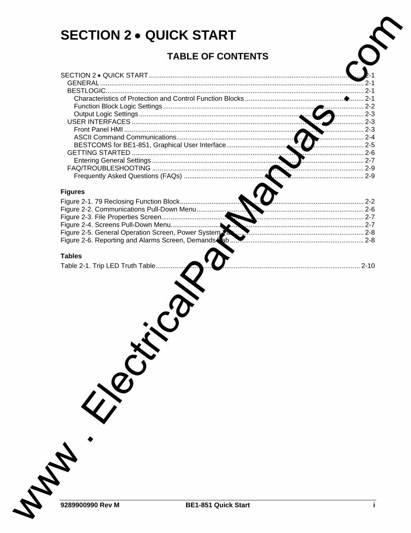
Figures Figure 2-1. 79 Reclosing Function Block................................................................................................... 2-2 Figure 2-2. Communications Pull-Down Menu.......................................................................................... 2-6 Figure 2-3. File Properties Screen............................................................................................................. 2-7 Figure 2-4. Screens Pull-Down Menu........................................................................................................ 2-7 Figure 2-5. General Operation Screen, Power System Tab ..................................................................... 2-8 Figure 2-6. Reporting and Alarms Screen, Demands Tab ........................................................................ 2-8
Tables Table 2-1. Trip LED Truth Table.............................................................................................................. 2-10
www . El
ectric
alPar
tMan
uals
. com

ii BE1-851 Quick Start 9289900990 Rev M
This page intentionally left blank.
www . El
ectric
alPar
tMan
uals
. com

9289900990 Rev M BE1-851 Quick Start 2-1
SECTION 2 • QUICK START GENERAL This section provides an overview of the BE1-851 Overcurrent Protection System. You should be familiar with the concepts behind the user interfaces and BESTlogic before you begin reading about the detailed BE1-851 functions. Sections 3 through 6 describe each function of the BE1-851 in detail. The following information is intended to provide the reader with a basic understanding of the three user interfaces (front panel HMI, ASCII serial communications link, and the BE1-851 BESTCOMS software) and the security features provided in the BE1-851 relay. Detailed information on the operation of the HMI (human-machine interface) can be found in Section 10, Human-Machine Interface, and the ASCII command communications in Section 11, ASCII Command Interface. Also covered in this section is an overview of BESTlogic, which is fundamental to how each of the protection and control functions are set up and used in the BE1-851 relay. Detailed information on using BESTlogic to design complete protection and control schemes for the protected circuit can be found in Section 7, BESTlogic, and Section 8, Application. Sections 3 through 6 describe each function provided in the BE1-851 relay and include references to the following items. Note that NOT all items are appropriate for each function.
• HMI Screens for setting the operational parameters. • ASCII commands for setting the operational parameters. • ASCII commands for setting up the BESTlogic required to use the function in your protection and
control scheme. • Outputs from the function such as alarm and BESTlogic variables or data reports. • HMI Screens for operation or interrogation of the outputs and reports provided by each function. • ASCII commands for operation or interrogation of the outputs and reports provided by each
function.
BESTLOGIC Each of the protection and control functions in the BE1-851 is implemented as an independent function block that is equivalent to a single function, discrete device counterpart. Each independent function block has all of the inputs and outputs that the discrete component counterpart might have. Programming BESTlogic is equivalent to choosing the devices required by your protection and control scheme and drawing schematic diagrams to connect the inputs and outputs to obtain the desired operational logic. The concept is the same but the method is different in that you choose each function block by enabling it and use Boolean logic expressions to connect the inputs and outputs. The result is that in designing your system, you have even greater flexibility than you had using discrete devices. An added benefit is that you are not constrained by the flexibility limitations inherent in many multifunction relays. One user programmable, custom logic scheme is in the user settings. To save you time, several preprogrammed logic schemes are also provided. Any of the preprogrammed schemes can be selected and used directly without having to make any BESTlogic settings. The logic scheme that is active is determined by a protection setting. Provisions have also been made to allow the protection engineer to copy one of the preprogrammed logic schemes into the user programmed custom logic settings so that it can simply be modified to fine tune it to the user’s requirements. There are two types of BESTlogic settings: function block logic settings and output logic settings. These are described briefly in the following paragraphs. Detailed information on using BESTlogic to design complete protection and control schemes for the protected circuit can be found in Section 7, BESTlogic Programmable Logic, and Section 8, Application.
Characteristics of Protection and Control Function Blocks As stated before, each function block is equivalent to a discrete device counterpart. For example, the recloser function block in the BE1-851 has all of the characteristics of a version of the BE1-79M reclosing relay with similar functionality. See Figure 2-1.
www . El
ectric
alPar
tMan
uals
. com

2-2 BE1-851 Quick Start 9289900990 Rev M
Figure 2-1. 79 Reclosing Function Block
Four inputs:
• RI (reclose initiate) • STATUS (breaker position) • WAIT • DTL/BLK (drive to lockout/block 79 operation)
Five Outputs:
• 79C (close) • 79RNG (recloser running) • 79F (reclose fail) • 79LO (lockout) • 79SCB (sequence controlled block signal)
One mode setting selected from three available settings:
• Disabled, power up to lockout mode, or power up to close mode Eight operational settings:
• Four reclose times (1, 2, 3, & 4) • Reset time • Reclose fail time • Max cycle time • Selected steps in the reclosing sequence that can be used to block tripping elements (same
functions as the toggle switches on the BE1-79M relay). Of the above characteristics, the operational settings are not included in the logic settings. They are contained in the protection settings. This is an important distinction. Since changing logic settings is similar to rewiring a panel, the logic settings are separate and distinct from the operational settings such as pickups and time delays.
Function Block Logic Settings To use a protection or control function block, the two items that need to be set are mode and input logic. The mode is equivalent to deciding which devices you want to install in your protection and control scheme. You then must set the logic variables that will be connected to the inputs.
www . El
ectric
alPar
tMan
uals
. com

9289900990 Rev M BE1-851 Quick Start 2-3
For example, the 51N function block has two modes (disabled and enabled) and one input, block (torque control). To use this function block, the logic setting command might be SL-51N=1,/IN2 for Set Logic-51N to be mode 1 (enabled) with the function blocked when contact sensing INput 2 is not (/) energized. Contact sensing input 2 would be wired to a ground relay enable switch. As noted before, the protection settings for this function block, pickup, time dial, and curve, must be set separately in the setting group settings. The setting might be S0-51N=6.5,2.1,S1R for Set in group 0 – the 51N function equal to pickup at 6.5 amps with a time dial of 2.1 using curve S1 with an integrating Reset characteristic. The 51N function block has two logic output variables, 51NT (Trip) and 51NPU (Picked Up). The combination of the logic settings and the operational settings for the function block govern how these variables respond to logic and current inputs.
Output Logic Settings BESTlogic, as implemented in the BE1-851, supports up to 16 output expressions. The output expressions are called virtual outputs to distinguish them from the physical output relays. VOA and VO1 through VO5 drive physical outputs Out A (fail safe alarm output) and Out 1 through Out 5, respectively. The rest of the virtual outputs can be used for intermediate logic expressions. For example, OUT1 is wired to the trip bus of the circuit breaker. To set up the logic to trip the breaker, the BESTlogic setting command might be SL-VO1=VO11+101T+BFPU for Set Logic – Virtual Output 1 = to Virtual Output 11 (which is the intermediate logic expression for all of the function block tripping outputs) or (+) 101T (the trip output of the virtual breaker control switch) or (+) BFPU (the pickup output of the breaker failure function block that indicates that breaker failure has been initiated).
USER INTERFACES Three user interfaces are provided for interacting with the BE1-851 relay: The front panel HMI, ASCII communications, and BESTCOMS communications software. The front panel HMI provides access to a subset of the total functionality of the device. ASCII communications provides access to all settings, controls, reports, and metering functions of the system. BESTCOMS for BE1-851 software provides a user friendly Windows ® environment for editing settings files and uploading and downloading them from the relay.
Front Panel HMI The front panel HMI consists of a two line by 16 characters LCD (liquid crystal display) with four scrolling pushbuttons, an edit pushbutton, and a reset pushbutton. The Edit pushbutton includes an LED to indicate when edit mode is active. There are five other LEDs for indicating power supply status, relay trouble alarm status, programmable major and minor alarm status, and a multipurpose trip LED that flashes to indicate that a protective element is picked up. The Trip LED lights continuously when the trip output is energized and seals in when a protective trip has occurred to indicate that target information is being displayed on the LCD. A complete description of the HMI is included in Section 10, Human-Machine Interface. The BE1-851 HMI is menu driven and organized into a menu tree structure with six branches. A complete menu tree description with displays is also provided in Section 10, Human-Machine Interface. A list of the menu branches and a brief description for scrolling through the menu is in the following paragraphs.
1. REPORT STATUS. Display and resetting of general status information such as targets, alarms, recloser status.
2. CONTROL. Operation of manual controls such as virtual switches, selection of active setting group, etc.
3. METERING. Display of real-time metering values. 4. REPORTS. Display and resetting of report information such as time and date, demand registers,
breaker duty statistics, etc. 5. PROTECTION. Display and setting of protective function setting parameters such as logic
scheme, pickups, time delays, etc. 6. GENERAL SETTINGS. Display and setting of non-protective function setting parameters such as
communication, LCD contrast, and CT ratios. Each screen in the menu tree displays the path in the upper left hand corner of the screen. Additionally, each screen is assigned a number in the HMI section. The number indicates the branch and level in the www .
Elec
tricalP
artM
anua
ls . c
om

2-4 BE1-851 Quick Start 9289900990 Rev M
menu tree structure. Screen numbering helps you to keep track of where you are when you leave the menu tree top level. You view each branch of the menu tree by using the RIGHT and LEFT scrolling pushbuttons. To go to a level of greater detail, you use the DOWN scrolling pushbutton. Each time a lower level in a menu branch is reached, the screen number changes to reflect the lower level. The following paragraphs and Figure 2-2 illustrate how the display screens are numbered in the menu tree. For example, to check or change the 51N pickup setting in setting group 3, you would press the RIGHT or LEFT scrolling pushbuttons to get to Screen 5 - PROTECTION LOGIC. You would then press the DOWN scrolling pushbutton to get to the next level of detail and the RIGHT or LEFT scrolling pushbutton to get to Screen 5.4 - SETTING GROUP 3. You would continue to press DOWN and RIGHT or LEFT scrolling pushbuttons to get to Screen 5.4.2 - 51 SETTINGS and then Screen 5.4.2.2 - 51N. On this screen, the pickup, time dial, and curve settings for the 51N function can be read and/or edited. To return to the top level from this location, you would press the UP scrolling pushbutton three times.
ASCII Command Communications The BE1-851 relay has three independent communications ports for serial communications. A computer terminal or PC running a terminal emulation program such as Windows® HyperTerminal® can be connected to any of the three ports so that commands can be sent to the relay. Communication with the relay uses a simple ASCII command language. When a command is entered via a serial port, the relay responds with the appropriate action. ASCII command communication is designed for both human-to-machine interactions and batch download type operations. The following paragraphs briefly describe the command structure and discuss human-to-machine interactions and batch command text file operations. The operation of the ASCII commands is described in detail in Section 11, ASCII Command Interface.
Command Structure An ASCII command consists of a command string made up of one or two letters followed by a hyphen and an object name. The first letter specifies the general command function and the second a sub-group. The object name is the specific function for which the command is intended. A command string entered by itself is a read command. A command string followed by an equal sign and one or more parameters is a write command. The general command groups are organized into five major groups plus several miscellaneous commands. These commands are as follows: C CONTROL. Commands to perform select before operate control actions such as tripping and closing
the circuit breaker, changing the active setting group, etc. Subgroups include S for Select and O for Operate.
G GLOBAL. Perform global operations that do not fall into the other general groups such as password security. Subgroups include: S for security settings.
M METERING. Read all real time metering values. This general command group has no subgroups. R REPORTS. Read and reset reporting functions such as time and date, demand registers, breaker
duty statistics, etc. Subgroups include: A for Alarm functions, B for Breaker monitoring functions, D for Demand recording functions, F for Fault summary reporting functions, G for General information, and S for Sequence of Events recorder functions.
S SETTINGS. Set all setting parameters that govern the functioning of the relay. Subgroups include: 0,1,2,3 for settings in setting groups, A for alarm settings, B for breaker monitoring settings, G for general settings, L for logic settings.
MISCELLANEOUS. Miscellaneous commands include ACCESS, EXIT, and HELP. Examples of object names would be 51N for the neutral inverse time overcurrent function or PIA for the A phase, peak current demand register. For example, to check the 51N pickup setting in setting group 3, you would enter S3-51N for Set, Group 3-51N. The relay would respond with the current pickup, time dial, and curve settings for the 51N function. To edit these settings the same command would be used with an = followed by the new settings and the enter pushbutton. Note that it is necessary to use the ACCESS and EXIT commands when using the write version of these commands.
Human-to-Machine ASCII Command Operations Using ASCII commands, settings can be read and changed on a function-by-function basis. The mnemonic format of the commands helps you interact with the relay. It isn't necessary to remember all of
www . El
ectric
alPar
tMan
uals
. com

9289900990 Rev M BE1-851 Quick Start 2-5
the object names. Most commands don't require that you specify a complete object name. If the first two letters of a command are entered, the relay will respond with all applicable object names. Example 1. Obtain a count of the breaker operations by entering RB (Report Breaker). The BE1-851
responds with the operations counter value along with all other breaker report objects. If you know that the object name for the breaker operations counter is OPCNTR, you can enter RB-OPCNTR and read only the number of breaker operations.
Partial object names are also supported. This allows multiple objects to be read or reset at the same time. Example 2. Read all peak-since-reset demand registers. Entering RD-PI (Report Demand - Peak
Current (I)) will return demand values and time stamps for phase A, B, C, Neutral, and Negative Sequence current. To read only the Neutral demand value, the full object name (RD-PIN) is entered. Entering RD-PI=0 resets all five of the peak-since-reset demand registers.
Batch Command Text File Operations With a few exceptions, each function of the relay uses one command to set it and each setting command operates on all of the parameters required by that function. See the example mentioned above in the paragraph titled Command Structure. This format results in a great many commands to fully set the relay. Also, the process of setting the relay does not use a prompting mode where the relay prompts you for each parameter in turn until you exit the setting process. For these reasons, a method for setting the relay using batch text files is recommended. In batch download type operations, the user creates an ASCII text file of commands and sends it to the relay. To facilitate this process, the response from a multiple read command is output from the BE1-851 in command format. So the user need only enter S for Set (with no subgroup) and the relay responds with all of the setting commands and their associated parameters. If the user enters S2 for Set Group 2, the relay responds with all of the setting commands for setting group 2. The user can capture this response to a file, edit it using any ASCII text editor, and then send the file back to the relay. See Section 11, ASCII Command Interface, for a more detailed discussion of how to use ASCII text files for setting the relay.
BESTCOMS for BE1-851, Graphical User Interface Basler Electric's graphical user interface (GUI) software is an alternative method for quickly developing setting files in a user-friendly, Windows® based environment. Using the GUI, you may prepare setting files off-line (without being connected to the relay) and then upload the settings to the relay at your convenience. These settings include protection and control, operating and logic, breaker and transformer monitoring, metering, and fault recording. Engineering personnel can develop, test, and replicate the settings before exporting it to a file and transmitting the file to technical personnel in the field. On the field end, the technician simply imports the file into the BESTCOMS database and uploads the file to the relay where it is stored in nonvolatile memory. The GUI also has the same preprogrammed logic schemes that are stored in the relay. This gives the engineer the option (off-line) of developing his setting file using a preprogrammed logic scheme, customizing a preprogrammed logic scheme, or building a scheme from scratch. Files may be exported from the GUI to a text editor where they can be reviewed or modified. The modified text file may then be uploaded to the relay. After it is uploaded to the relay, it can be brought into the GUI but it cannot be brought directly into the GUI from the text file. The GUI logic builder uses basic AND/OR gate logic combined with point and click variables to build the logic expressions. This reduces the design time and increases dependability. The GUI also allows for downloading industry standard COMTRADE files for analysis of stored oscillography data. Detailed analysis of the oscillography files may be accomplished using Basler Electric's BESTWAVE software. For more information on Basler Electric's Windows® based BESTCOMS (GUI) software or BESTWAVE, contact your local sales representative or Basler Electric Technical Support Services Department in Highland, Illinois.
www . El
ectric
alPar
tMan
uals
. com

2-6 BE1-851 Quick Start 9289900990 Rev M
GETTING STARTED Refer to Section 12, Installation, for typical external connection diagrams. If your relay has power supply option 1 or 2, it can be supplied by normal 120 Vac house power. These two power supply options (1 and 2) are the midrange and high range AC/DC power supplies. The contact sensing inputs are half-wave rectified opto-isolators. The default contact recognition and debounce settings enable their use on ac signals as well as dc signals. The relay measures the A phase, B phase, and C phase current magnitudes directly from the three current sensing inputs on Circuit #1 (this is dependent on style configuration). Circuit #2 measures the A phase, B phase, and C phase current magnitudes directly from the three current sensing inputs. The neutral and negative sequence magnitudes are calculated from the fundamental component of each of the three-phase currents. When evaluating the negative sequence functions, the relay can be tested using a two-phase current source. To fully evaluate the operation of the relay in the power system, it is desirable to use a three-phase current source. Using a serial cable, connect a computer to the relays front RS-232 port. Install BE1-851 BESTCOMS according to the procedure given in Section 14, BESTCOMS Software. Once BESTCOMS is installed, apply power to the relay. From the Basler Electric program group on your windows Start menu, select BESTCOMS for BE1-851 to start BESTCOMS. From the Communication pull-down menu, select Configure and verify communication is configured correctly. Once communication settings are correct, from the Communication pull-down menu select Download Settings from Device (Figure 2-2). This command will transfer the relays current settings to the BESTCOMS software, allowing the settings to be viewed easily in a windows environment. Before continuing, select the Save As command from the File menu. The File Properties Screen for the file you are saving will appear. Refer to Figure 2-3. Type in any comments about the file and select OK. The Save As dialog box will appear. Give the file a unique name that you will recognize at a later date and select Save. This action does not send the settings to the relay but rather saves them in a BESTCOMS settings file with a .bst extension. Once saved, the settings file may be retrieved, modified, and transmitted to the relay at any time.
Figure 2-2. Communications Pull-Down Menu
www . El
ectric
alPar
tMan
uals
. com
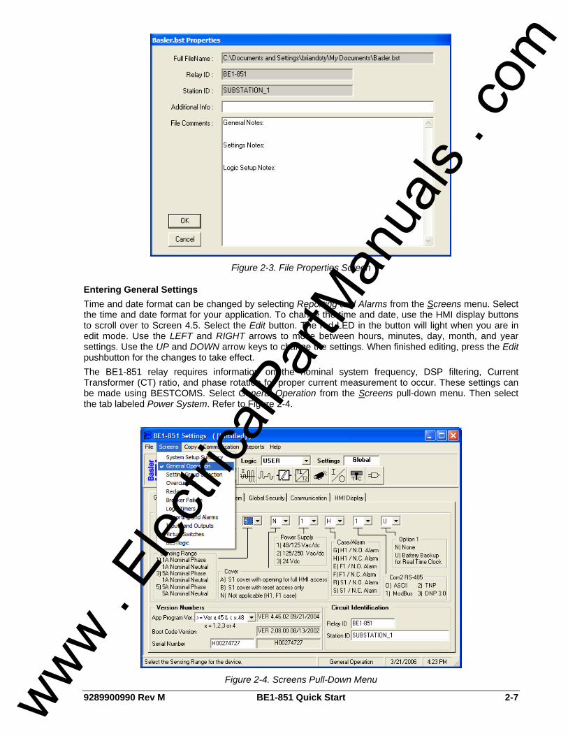
9289900990 Rev M BE1-851 Quick Start 2-7
Figure 2-3. File Properties Screen
Entering General Settings Time and date format can be changed by selecting Reporting and Alarms from the Screens menu. Select the time and date format for your application. To change the time and date, use the HMI display buttons to scroll over to Screen 4.5. Select the Edit button. The red LED in the button will light when you are in edit mode. Use the LEFT and RIGHT arrows to move between hours, minutes, day, month, and year settings. Use the UP and DOWN arrow keys to change the settings. When finished editing, press the Edit pushbutton for the changes to take effect. The BE1-851 relay requires information on the nominal system frequency, DSP filtering, Current Transformer (CT) ratio, and phase rotation for proper current measurement to occur. These settings can be made using BESTCOMS. Select General Operation from the Screens pull-down menu. Then select the tab labeled Power System. Refer to Figure 2-4.
Figure 2-4. Screens Pull-Down Menu
www . El
ectric
alPar
tMan
uals
. com
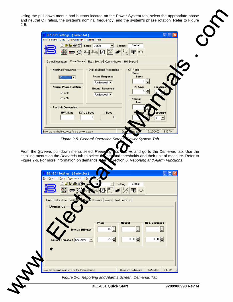
2-8 BE1-851 Quick Start 9289900990 Rev M
Using the pull-down menus and buttons located on the Power System tab, select the appropriate phase and neutral CT ratios, the system's nominal frequency, and the system's phase rotation. Refer to Figure 2-5.
Figure 2-5. General Operation Screen, Power System Tab
From the Screens pull-down menu, select Reporting and Alarms and go to the Demands tab. Use the scrolling menus on the Demands tab to select the demand thresholds and their unit of measure. Refer to Figure 2-6. For more information on demands refer to Section 6, Reporting and Alarm Functions.
Figure 2-6. Reporting and Alarms Screen, Demands Tab
www . El
ectric
alPar
tMan
uals
. com

9289900990 Rev M BE1-851 Quick Start 2-9
Use the remaining screens and associated tabs to make additional settings required for evaluation of the relay. Save the file. From the Communication pull-down menu, select Upload Settings to Device to send the settings to the relay. The relay's inputs and outputs as well as targets, alarms and current metering can be monitored from the Metering Screen. To open the Metering Screen, select Metering from the Reports pull-down menu. To begin viewing the relays metered values, select the Start Polling button in the bottom right hand corner of the screen.
FAQ/TROUBLESHOOTING
Frequently Asked Questions (FAQs) 1.) Why won't the trip LED reset when I press the RESET key on the front panel? The Reset key is context sensitive. To reset the trip LED or the targets, the Target Screen must
be displayed. To reset the alarms, the Alarm Screen must be displayed.
2.) Is the power supply polarity sensitive? No, the power supply will accept either an ac or dc voltage input. However, the contact sensing
for the programmable inputs is polarity sensitive. See Section 12, Installation, for a typical interconnection diagram.
3.) What voltage level is used to develop current flow through the contact sensing inputs? Voltage level is dependent on the power supply option (BE1-851 style) and the position of the
contact sensing jumper. See Section 12, Installation, for additional information.
4.) Does the BE1-851 trip output contact latch after a fault? The answer to the question is Yes and No. In general, once the fault goes away the output
contacts open. The BE1-851 does offer an option to ensure that the contact will stay closed for at least 200 milliseconds. See Section 3, Input and Output Functions, and Section 8, Application, for additional information on that function. But, BESTlogic can latch the relay outputs. Refer to, Section 8, Application, Application Tips, for additional information.
5.) Why won't a function work when I put in settings such as the pickup and time delays?
Make sure that the protective element is enabled in BESTlogic.
6.) Can I make logic settings from the front panel? No, the front panel cannot program logic settings. Logic settings must be programmed using the
ASCII command interface or BESTCOMS communication software. 7.) Does the BE1-851 have a battery installed as the back-up power source for the internal
clock on loss of power? No, the BE1-851 does not have a battery unless the option is specified. Without the battery
option, you have to reset the time and date every time you lose power. You can use the IRIG to automatically reset the time and date.
8.) Why do I keep getting access conflict errors when I am communicating with the relay?
Access can be granted to only one communication port at a time. The HMI is considered to be the same port as the front RS-232 communication port. The unit has three different communication ports. The front HMI and front RS-232 (COM 0) is the first port. The rear RS-232 (COM 1) is the second and the rear RS-485 (COM 3) is the third port. If you have gained access at the front panel HMI and the 5-minute time out has not ended, you cannot gain access at another port. The front RS-232 can still be accessed because HMI and the front RS-232 are considered to be the same port. If you have tried to gain access to more than one port at a time, an access conflict results. Access only needs to be gained when a change of a setting is needed. To read data or to get any reports this can be done without gaining access. After www . El
ectric
alPar
tMan
uals
. com

2-10 BE1-851 Quick Start 9289900990 Rev M
gaining access though one of the ports a session can be ended with an "Exit" command. If access is gained, but the session is not ended, a 5-minute time out will end the session and any changes that were not saved will be lost. If you are using the BESTCOMS program, the gaining access and the exit commands are done for you.
9.) Why doesn't the trip LED behave as expected when the relay picks up and trips? Another
closely related question would be, "Why don't the targets work?" If the logic is setup to the point were the protective element is tripping at the desired current
level, but the targets, Trip LED and fault records are not behaving as expected, then there are two commands that need to be checked for proper operation. The SG-TRIGGER command needs to have the PU trigger and TRIP trigger logic correctly programmed. This should initiate the fault record. The SG-TARGET command needs that protective element (function) enabled to log targets. Please refer Section 6, Reporting and Alarm Functions in the Instruction Manual under the section Fault Reporting to get further details on how to program these commands correctly. The Trip LED has two different functions in the relay. When the SG-TRIGGER PU expression is true, and the TRIP expression is false, the Trip LED flashes. When both the SG-TRIGGER TRIP and PU expression are true, the Trip LED lights solidly. When neither expression is true, the trip LED lights solidly if there are latched targets. A flashing LED means one of the protection elements is in a pickup state and timing towards trip. Once the trip occurs, the LED turns on solid. The LED will not change state until the target has been reset. If the fault has not cleared, the LED will turn on again.
Table 2-1. Trip LED Truth Table
SG-TRIGGER PU SG-TRIGGER TRIP Targets Latched Trip LED
True False No Flashes
True True No Lights Solid
False False Yes Lights Solid
10.) Is the IRIG signal modulated or demodulated?
The IRIG signal is demodulated (dc level-shifted digital signal). See Section 1, General Information, Operational Specifications, and Section 8, Application, for additional information.
11.) Can the IRIG signal be daisy-chained to multiple BE1-851 units? Yes, multiple BE1-851 units can use the same IRIG-B input signal by daisy-chaining the BE1-
851 inputs. The burden data is non-linear, approximately 4 k-ohms at 3.5 Vdc and 3 k-ohms at 20 Vdc. See, Section 8, Application, and Section 3, Input and Output Functions, for additional information.
12.) How can I find out what the version number is of my BE1-851?
The application version can be found in three different ways. One, use the HMI, Screen 4.6. Two, use the ASCII command interface with the RG-VER command. Three, use BESTCOMS for BE1-851. (The version is provided on the General Information tab of the General Operation screen.)
www . El
ectric
alPar
tMan
uals
. com
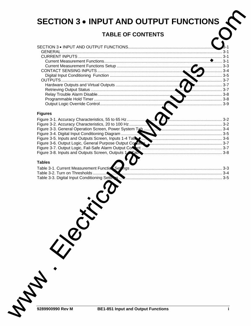
9289900990 Rev M BE1-851 Input and Output Functions i
SECTION 3 • INPUT AND OUTPUT FUNCTIONS TABLE OF CONTENTS
SECTION 3 • INPUT AND OUTPUT FUNCTIONS................................................................................... 3-1
GENERAL.............................................................................................................................................. 3-1 CURRENT INPUTS ............................................................................................................................... 3-1
Current Measurement Functions........................................................................................................ 3-1 Current Measurement Functions Setup ............................................................................................. 3-3
CONTACT SENSING INPUTS .............................................................................................................. 3-4 Digital Input Conditioning Function ................................................................................................... 3-5
OUTPUTS.............................................................................................................................................. 3-7 Hardware Outputs and Virtual Outputs .............................................................................................. 3-7 Retrieving Output Status .................................................................................................................... 3-7 Relay Trouble Alarm Disable.............................................................................................................. 3-8 Programmable Hold Timer ................................................................................................................. 3-8 Output Logic Override Control............................................................................................................ 3-9
Figures Figure 3-1. Accuracy Characteristics, 55 to 65 Hz .................................................................................... 3-2 Figure 3-2. Accuracy Characteristics, 20 to 100 Hz.................................................................................. 3-2 Figure 3-3. General Operation Screen, Power System Tab ..................................................................... 3-4 Figure 3-4. Digital Input Conditioning Diagram ......................................................................................... 3-5 Figure 3-5. Inputs and Outputs Screen, Inputs 1-4 Tab............................................................................ 3-6 Figure 3-6. Output Logic, General Purpose Output Contacts ................................................................... 3-7 Figure 3-7. Output Logic, Fail-Safe Alarm Output Contact ....................................................................... 3-7 Figure 3-8. Inputs and Outputs Screen, Outputs 1-5 Tab ......................................................................... 3-8
Tables Table 3-1. Current Measurement Function Settings ................................................................................. 3-3 Table 3-2. Turn on Thresholds .................................................................................................................. 3-4 Table 3-3. Digital Input Conditioning Settings ........................................................................................... 3-5
www . El
ectric
alPar
tMan
uals
. com

ii BE1-851 Input and Output Functions 9289900990 Rev M
This page intentionally left blank.
www . El
ectric
alPar
tMan
uals
. com

9289900990 Rev M BE1-851 Input and Output Functions 3-1
SECTION 3 • INPUT AND OUTPUT FUNCTIONS GENERAL The BE1-851 inputs consist of three-phase current inputs, neutral current inputs, and four contact sensing inputs. Five general-purpose output contacts and one dedicated, fail-safe alarm output make up the BE1-851 outputs. Each input and output is isolated and terminated at separate terminal blocks. This section describes the function and setup of each input and output.
CURRENT INPUTS Secondary current from power system equipment CT is applied to current transformers inside the relay. These internal transformers step down the monitored current to levels compatible with relay circuitry and provide isolation. Secondary current from each internal CT is converted to a voltage signal and then filtered by an analog, low-pass, anti-aliasing harmonic filter.
Current Measurement Functions The power system analog quantities for phase, neutral, and negative-sequence currents are calculated and used by all of the current dependent functions of the relay. There is no separate positive or zero-sequence value calculated. The filter response for phase and neutral calculations can be independently programmed. Operation of the current measurement function is governed by settings for nominal frequency, digital signal processing algorithm, current transformer ratio, and normal phase rotation.
Nominal Frequency Input waveforms are sampled by an analog-to-digital converter at 24 samples per cycle. A nominal frequency of either 50 or 60 Hz must be selected in order for the analog-to-digital converter to sample analog quantities at appropriate time intervals to achieve 24 samples per cycle.
Digital Signal Processing The digital signal processing (DSP) setting governs how the phase and neutral operating quantities are measured. The negative-sequence current is derived from the phase currents and is not independently settable. The three choices are Fundamental, RMS, and Average. This is independently settable for the phase and neutral quantities. Each setting causes the relay to respond differently in the presence of significant harmonics and for operation at significantly off-nominal frequency. Accuracy characteristics for each algorithm (Fundamental, RMS, and Average) are shown in Figure 3-1. This figure is for a 60 Hz nominal system with frequencies between 55 and 65 Hz. A 50 Hz nominal system would have similar characteristics. The fundamental setting (F) uses a Fourier filter to extract the fundamental frequency component of the measured current and reject the harmonic frequency components. This setting is best suited for most protection purposes due to its superior transient overreach and fast dropout characteristics. It is also recommended for applications where harmonic rejection is desired. For example, in a neutral circuit where the third harmonic component is additive and can result in unwanted tripping. The RMS setting uses a true RMS calculation to include harmonic components of the measured current. The presence of significant levels of harmonics can cause heating in protected equipment and increased sensitivity in electro-mechanical devices. This setting is recommended for equipment applications that require thermal overload protection. It is also recommended for applications where the transient overreach and sensitivity characteristics provide better coordination with induction disk type overcurrent protection systems.
www . El
ectric
alPar
tMan
uals
. com

3-2 BE1-851 Input and Output Functions 9289900990 Rev M
D2647-2809-10-03
Figure 3-1. Accuracy Characteristics, 55 to 65 Hz
The Average setting uses a digital measurement circuit. This circuit consists of a full wave rectifier with a two pole, low pass filter. A third digital filter tuned to the nominal frequency removes the ripple error that is inherent in this type of circuit. Due to the low pass filter, this setting has slower pickup and dropout characteristics than the other two settings. This setting is recommended in applications where protection is desired at frequencies that deviate significantly from nominal. The characteristics of the three algorithms from 20 to 100 Hz is shown in Figure 3-2. This plot is based on a setting of 60 Hz nominal (20 to 100 Hz). This setting also provides good coordination with induction disk type overcurrent relays and provides superior transient overreach characteristics.
D2647-2905-29-03
Figure 3-2. Accuracy Characteristics, 20 to 100 Hz
www . El
ectric
alPar
tMan
uals
. com

9289900990 Rev M BE1-851 Input and Output Functions 3-3
Negative-Sequence Current Negative-Sequence components are measured from the fundamental component of the three-phase current inputs. The relay can be set to accommodate ABC or ACB phase-sequence when calculating the negative-sequence component.
Neutral Current The current entering “D7” and leaving “D8” will be understood by the relay to be the neutral current. If nothing is connected, the relay will understand the neutral current to be zero. No neutral current will be calculated from any phase imbalance.
Fast-Dropout Current Detector A separate, fast-dropout current measurement algorithm is used by the breaker failure function and the breaker trip-speed monitoring function. This measurement algorithm has a sensitivity of 10 percent of nominal rating and detects current interruption in the circuit breaker much more quickly than the regular current measurement functions.
Current Measurement Functions Setup Current Input Circuit Settings. The BE1-851 requires information on the nominal system frequency, DSP filtering, CT ratio, and phase rotation. These settings are used by the metering and fault reporting functions to display measured quantities in primary units. The se settings can be entered at the HMI, see Section 10, Human-Machine Interface, or through the communication ports using the SG-FREQ, SG-DSP, SG-CT, and SG-PHROT setting general commands. Settings relating to current measurement are summarized in Table 3-1.
Table 3-1. Current Measurement Function Settings
Settings Password Access Range Default Unit of
Measure
Nominal Frequency Privilege G or S 50 or 60 60 Hertz
Digital Signal Processing for Phase and Neutral Response Privilege G or S Average, Fundamental,
RMS Fundamental N/A
Normal Phase Rotation None ABC or ACB ABC N/A
CT Ratio, Phase, and Neutral None 1 to 50,000 (Increment of 1) 1 Turns
CT ratio for phase and neutral, as shown in the table above, uses turns as its unit of measure. Note that the CT ratio can also be input as a ratio as in the example below (50:5). BESTCOMS will calculate either turns or primary amps depending on which value is entered. BESTCOMS does not calculate secondary amps. To make the settings using BESTCOMS, select General Operation from the Screens pull-down menu. Then select the Power System tab. Make selections for the above settings by using the appropriate pull-down menus and buttons on the Power System tab. Example 1. Make the following settings in BESTCOMS (refer to Figure 3-3): Nominal Frequency: 60 Hz Digital Signal Processing, Phase Response: RMS Digital Signal Processing, Neutral Response: Fundamental Normal Phase Rotation: ACB CT Ratio, Phase: 800:5 CT Ratio, Neutral: 50:5
www . El
ectric
alPar
tMan
uals
. com

3-4 BE1-851 Input and Output Functions 9289900990 Rev M
Figure 3-3. General Operation Screen, Power System Tab
CONTACT SENSING INPUTS BE1-851 relays have four contact sensing inputs to initiate BE1-851 relay actions. These inputs are isolated and require an external wetting voltage. Nominal voltage(s) of the external dc source(s) must fall within the relay dc power supply input voltage range. To enhance user flexibility, the BE1-851 relay uses wide range AC/DC power supplies that cover several common control voltage ratings. To further enhance flexibility, the input circuits are designed to respond to voltages at the lower end of the control voltage range while not overheating at the high end of the control voltage range. Energizing levels for the contact sensing inputs are jumper selectable for a minimum of approximately 5 Vdc for 24 Vdc nominal sensing voltages, 26 Vac or Vdc for 48/125 Vac or Vdc nominal sensing voltages or 69 Vac or Vdc for 125/250 Vac or Vdc nominal sensing voltages. See Table 3-2 for the control voltage ranges. Each BE1-851 is delivered without the contact sensing jumpers installed. The operation will be in the higher end of the control voltage range. If the contact sensing inputs are to be operated at the lower end of the control voltage range, the jumpers must be installed. See Section 12, Installation, for details on how to set the jumper positions in the contact sensing input circuits.
Table 3-2. Turn on Thresholds
Nominal Turn-On Voltage Range Nominal Control
Voltage Jumper Installed (Low Position)
Jumper Not Installed (High Position)
24 Vdc N/A Approx. 5 Vdc
48/125 Vac or Vdc 26 - 38 Vac or Vdc 69 - 100 Vac or Vdc
125/250 Vac or Vdc 69 - 100 Vac or Vdc 138 - 200 Vac or Vdc
www . El
ectric
alPar
tMan
uals
. com

9289900990 Rev M BE1-851 Input and Output Functions 3-5
Digital Input Conditioning Function Status of the contact sensing inputs is checked 24 times per cycle. When operating on a 60 Hz power system, this results in the input status being sampled every 0.7 milliseconds (0.8 milliseconds on 50 Hz systems). User settable digital contact recognition and debounce timers condition the signals applied to the inputs. These parameters can be adjusted to obtain the optimum compromise between speed and security for a specific application. Digital input conditioning is evaluated every quarter cycle. If the sampled status of a monitored contact is detected as energized for the recognition time, the logic variable changes from a de-energized (logic 0 or FALSE) state to an energized (logic 1 or TRUE) state. Once contact closure is recognized, the logic variable remains in the energized state until the sampled status of the monitored contact is detected to be open for a period that is longer than the debounce time. At this point, the logic variable will change from an energized (logic 1 or TRUE) state to a de-energized (logic 0 or FALSE) state. See Figure 3-4.
Figure 3-4. Digital Input Conditioning Diagram
Setting Up the Digital Input Conditioning Function The settings for the digital input signal conditioning function and related BESTCOMS features are shown in Table 3-3. Digital input conditioning settings could be entered using BESTCOMS. Alternately, the setting may be entered through the communication ports using the SG-IN ASCII command.
Table 3-3. Digital Input Conditioning Settings
Setting Range Increment Unit of Measure Default
Recognition Time 4 to 255 1∗ Milliseconds 4
Debounce Time 4 to 255 1∗ Milliseconds 16
Time Units Pull-down menu that selects the unit of measure for Recognition Time and Debounce Time. Units of measure available are: milliseconds, seconds, minutes, and cycles. The default is milliseconds.
Name User programmable label for the input contact. Used by the reporting function to give meaningful identification to the input contact. This label may be up to 10 characters long.
Energized State User programmable label for the contact’s energized state. It is used by the reporting function to give meaningful identification to the state of the input contact. This label may be up to seven characters long.
De-Energized StateUser programmable label for the contact’s de-energized state. It is used by the reporting function to give meaningful identification to the state of the input contact. This label may be up to seven characters long.
∗ Since the input conditioning function is evaluated every quarter cycle, the setting is internally rounded to the nearest multiple of 4.16 milliseconds (60 Hz systems) or 5 milliseconds (50 Hz systems).
www . El
ectric
alPar
tMan
uals
. com

3-6 BE1-851 Input and Output Functions 9289900990 Rev M
If you are concerned about ac voltage being coupled into the contact sensing circuits, the recognition time can be set to greater than one-half of the power system cycle period. This will take advantage of the half-wave rectification provided by the input circuitry. If an ac wetting voltage is used, the recognition time can be set to less than one-half of the power system cycle period and the debounce timer can be set to greater than one-half of the power system cycle period. The extended debounce time will keep the input energized during the negative half-cycle. The default settings of 4 and 16 milliseconds are compatible with ac wetting voltages. To make the settings using BESTCOMS, select Inputs and Outputs from the Screens pull-down menu. Then select the Inputs 1-4 tab. Make selections for the settings in Table 3-3 by using the appropriate pull-down menus, buttons, and text boxes on the Power System tab. Example 1. Make the following setting for Input 1 (refer to Figure 3-5): Recognition Time: 6 ms Debounce Time: 20 ms Name: BREAKER Energized State: OPEN De-Energized State: CLOSED
Figure 3-5. Inputs and Outputs Screen, Inputs 1-4 Tab
Retrieving Input Status Information from the Relay The relay’s inputs can be monitored from the Metering screen in BESTCOMS. To open the Metering screen, select Metering from the Reports pull-down menu. To begin viewing the relay’s metered values, select the Start Polling button in the bottom right hand corner of the screen. Alternately, input status is determined through HMI Screen 1.5.1 or through the communication ports using the RG-STAT (report general-status) command. See Section 6, Reporting and Alarm Functions, General Status Reporting, for more information.
www . El
ectric
alPar
tMan
uals
. com
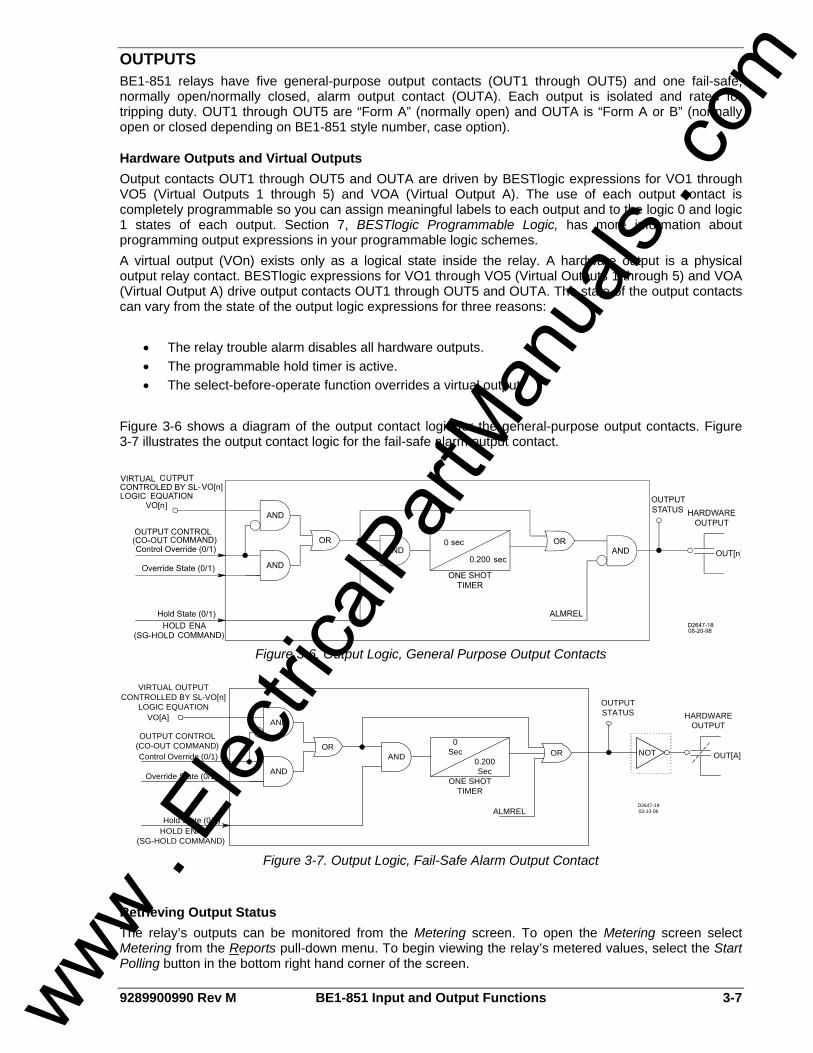
9289900990 Rev M BE1-851 Input and Output Functions 3-7
OUTPUTS BE1-851 relays have five general-purpose output contacts (OUT1 through OUT5) and one fail-safe, normally open/normally closed, alarm output contact (OUTA). Each output is isolated and rated for tripping duty. OUT1 through OUT5 are “Form A” (normally open) and OUTA is “Form A or B” (normally open or closed depending on BE1-851 style number, case option).
Hardware Outputs and Virtual Outputs Output contacts OUT1 through OUT5 and OUTA are driven by BESTlogic expressions for VO1 through VO5 (Virtual Outputs 1 through 5) and VOA (Virtual Output A). The use of each output contact is completely programmable so you can assign meaningful labels to each output and to the logic 0 and logic 1 states of each output. Section 7, BESTlogic Programmable Logic, has more information about programming output expressions in your programmable logic schemes. A virtual output (VOn) exists only as a logical state inside the relay. A hardware output is a physical output relay contact. BESTlogic expressions for VO1 through VO5 (Virtual Outputs 1 through 5) and VOA (Virtual Output A) drive output contacts OUT1 through OUT5 and OUTA. The state of the output contacts can vary from the state of the output logic expressions for three reasons:
• The relay trouble alarm disables all hardware outputs. • The programmable hold timer is active. • The select-before-operate function overrides a virtual output.
Figure 3-6 shows a diagram of the output contact logic for the general-purpose output contacts. Figure 3-7 illustrates the output contact logic for the fail-safe alarm output contact.
Figure 3-6. Output Logic, General Purpose Output Contacts
0.200 Sec
0 Sec OR
ONE SHOT TIMER
AND OUT[A]
HARDWAREOUTPUT
OUTPUTSTATUS
AND
AND
ORControl Override (0/1)
Override State (0/1)
Hold State (0/1)
VO[A]
VIRTUAL OUTPUT CONTROLLED BY SL-VO[n]
LOGIC EQUATION
HOLD ENA(SG-HOLD COMMAND)
OUTPUT CONTROL (CO-OUT COMMAND)
ALMRELD2647-1903-13-06
NOT
Figure 3-7. Output Logic, Fail-Safe Alarm Output Contact
Retrieving Output Status The relay’s outputs can be monitored from the Metering screen. To open the Metering screen select Metering from the Reports pull-down menu. To begin viewing the relay’s metered values, select the Start Polling button in the bottom right hand corner of the screen.
www . El
ectric
alPar
tMan
uals
. com
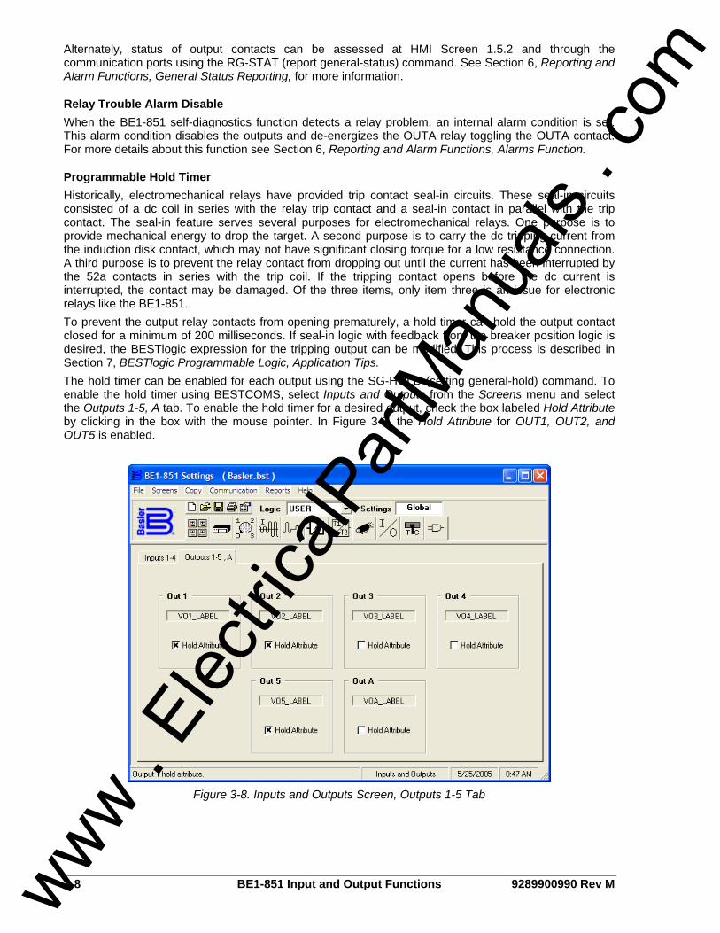
3-8 BE1-851 Input and Output Functions 9289900990 Rev M
Alternately, status of output contacts can be assessed at HMI Screen 1.5.2 and through the communication ports using the RG-STAT (report general-status) command. See Section 6, Reporting and Alarm Functions, General Status Reporting, for more information.
Relay Trouble Alarm Disable When the BE1-851 self-diagnostics function detects a relay problem, an internal alarm condition is set. This alarm condition disables the outputs and de-energizes the OUTA relay toggling the OUTA contact. For more details about this function see Section 6, Reporting and Alarm Functions, Alarms Function.
Programmable Hold Timer Historically, electromechanical relays have provided trip contact seal-in circuits. These seal-in circuits consisted of a dc coil in series with the relay trip contact and a seal-in contact in parallel with the trip contact. The seal-in feature serves several purposes for electromechanical relays. One purpose is to provide mechanical energy to drop the target. A second purpose is to carry the dc tripping current from the induction disk contact, which may not have significant closing torque for a low resistance connection. A third purpose is to prevent the relay contact from dropping out until the current has been interrupted by the 52a contacts in series with the trip coil. If the tripping contact opens before the dc current is interrupted, the contact may be damaged. Of the three items, only item three is an issue for electronic relays like the BE1-851. To prevent the output relay contacts from opening prematurely, a hold timer can hold the output contact closed for a minimum of 200 milliseconds. If seal-in logic with feedback from the breaker position logic is desired, the BESTlogic expression for the tripping output can be modified. This process is described in Section 7, BESTlogic Programmable Logic, Application Tips. The hold timer can be enabled for each output using the SG-HOLD (setting general-hold) command. To enable the hold timer using BESTCOMS, select Inputs and Outputs from the Screens menu and select the Outputs 1-5, A tab. To enable the hold timer for a desired output, check the box labeled Hold Attribute by clicking in the box with the mouse pointer. In Figure 3-8, the Hold Attribute for OUT1, OUT2, and OUT5 is enabled.
Figure 3-8. Inputs and Outputs Screen, Outputs 1-5 Tab
www . El
ectric
alPar
tMan
uals
. com

9289900990 Rev M BE1-851 Input and Output Functions 3-9
Output Logic Override Control Each output contact can be controlled directly using the select-before-operate output control function. The virtual output logic expression that normally controls the state of an output contact can be overridden and the contact pulsed, held open, or held closed. This function is useful for testing purposes. An alarm point is available in the programmable alarm function for monitoring when the output logic has been overridden. See Section 6, Reporting and Alarm Functions, Alarms Function, for more information about programmable alarms. Write access to control functions is required before using the select-before-operate control functions through the HMI or ASCII command interface.
Enabling Logic Override Control By default, logic override control is disabled. Output logic override must be enabled before the control can be used. Enabling of the output logic override control is not possible at the front panel HMI or through BESTCOMS. It can only be enabled through a communication port using the CS/CO-OUT=ena/dis (control select/control operate-output override = enable/disable) command. The CS/CO-OUT command only enables or disables override control of the output logic; it doesn’t enable or disable the outputs themselves.
Pulsing an Output Contact Pulsing BE1-851 outputs provides the same function as the push-to-energize feature of other Basler Electric solid-state relays. This feature is useful when testing the protection and control system. When pulsed, an output contact changes from the current state (as determined by the virtual output logic expression) to the opposite state for 200 milliseconds. After 200 milliseconds, the output contact is returned automatically to logic control.
Holding an Output Contact Open or Closed Outputs can be forced to a closed (logic 1 or TRUE) state or to an open (logic 0 or FALSE) state. This feature can be used to disable a contact during testing. Open or close logic override control is accessed at Screen 2.4.1 of the HMI by entering a 0 for open or 1 for closed in the field for the output contact to be controlled. Outputs are forced open or closed through a communication port by using the CS/CO-OUTn=P0/1 (control select/control operate-output contact n-0/1) command.
Returning an Output Contact to Logic Control When the output logic has been overridden and the contact is held in an open or closed state, it’s necessary to manually return the output to logic control. Outputs are returned to logic control through Screen 2.4.1 of the HMI. An L is entered in the field of the contact that is to be returned to logic control. Outputs are returned to logic control through a communication port by using the CS/CO-OUTn=L (control select/control operate-output contact n-0/1) command. The output control commands require the use of select-before-operate logic. First, the command must be selected using the CS-OUT command. After the command is selected, there is a 30 second window during which the CO-OUT control command can be entered. The control selected and operation selected syntax must match exactly or the command will be blocked. If the operate command isn’t entered within 30 seconds of the select command, the operate command will be blocked. An error message is returned when a control command is blocked. Output control commands are acted on immediately except when the ENA and DIS modes are used. ENA and DIS output control command changes aren’t executed until saved with the EXIT command. Output control status is saved in non-volatile memory and is maintained when the relay operating power is lost. All relay responses in the following examples and throughout the manual are printed in Courier New typeface.
www . El
ectric
alPar
tMan
uals
. com

3-10 BE1-851 Input and Output Functions 9289900990 Rev M
1. Enable the output control feature. >CS-OUT=ENA OUT=ENA SELECTED >CO-OUT=ENA OUT=ENA EXECUTED >E (exit) Save Changes (Y/N/C)? >Y (yes)
2. Test all outputs by pulsing momentarily. >CS-OUT=P OUT=P SELECTED >CO-OUT=P OUT=P EXECUTED
3. Disable the trip output (OUT1) by holding it at logic 0. >CS-OUT1=0 OUT1=0 SELECTED >CO-OUT1=0 OUT1=0 EXECUTED
4. Return OUT1 to logic control. >CS-OUT1=L OUT1=L SELECTED >CO-OUT1=0 OUT1=L EXECUTED
5. Disable the output control feature. >CS-OUT=DIS OUT=DIS SELECTED >CO-OUT=DIS OUT=DIS EXECUTED >E (exit) Save Changes (Y/N/C)? >Y (yes)
Retrieving Output Logic Override Status The status of the output contact logic override control can be viewed at HMI Screen 1.5.3. HMI Screen 2.4.1 is used for output control but can also display the current status. Output logic status can also be viewed using the RG-STAT (report general-status) command. An L indicates that the state of the output is controlled by logic. A 0 or 1 indicates that the logic has been overridden and the contact is held open (0) or closed (1) state. A P indicates that the contact is being pulsed and will return to logic control automatically. See Section 6, Reporting and Alarm Functions, General Status Reporting, for more information.
www . El
ectric
alPar
tMan
uals
. com
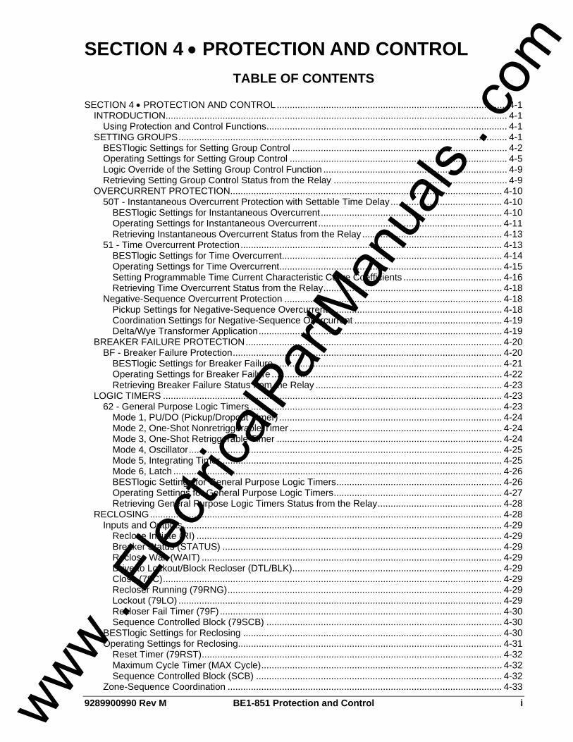
9289900990 Rev M BE1-851 Protection and Control i
SECTION 4 • PROTECTION AND CONTROL TABLE OF CONTENTS
SECTION 4 • PROTECTION AND CONTROL......................................................................................... 4-1
INTRODUCTION.................................................................................................................................... 4-1 Using Protection and Control Functions............................................................................................. 4-1
SETTING GROUPS............................................................................................................................... 4-1 BESTlogic Settings for Setting Group Control ................................................................................... 4-2 Operating Settings for Setting Group Control .................................................................................... 4-5 Logic Override of the Setting Group Control Function ....................................................................... 4-9 Retrieving Setting Group Control Status from the Relay ................................................................... 4-9
OVERCURRENT PROTECTION......................................................................................................... 4-10 50T - Instantaneous Overcurrent Protection with Settable Time Delay........................................... 4-10
BESTlogic Settings for Instantaneous Overcurrent...................................................................... 4-10 Operating Settings for Instantaneous Overcurrent....................................................................... 4-11 Retrieving Instantaneous Overcurrent Status from the Relay ...................................................... 4-13
51 - Time Overcurrent Protection..................................................................................................... 4-13 BESTlogic Settings for Time Overcurrent..................................................................................... 4-14 Operating Settings for Time Overcurrent...................................................................................... 4-15 Setting Programmable Time Current Characteristic Curve Coefficients ...................................... 4-16 Retrieving Time Overcurrent Status from the Relay..................................................................... 4-18
Negative-Sequence Overcurrent Protection .................................................................................... 4-18 Pickup Settings for Negative-Sequence Overcurrent................................................................... 4-18 Coordination Settings for Negative-Sequence Overcurrent ......................................................... 4-19 Delta/Wye Transformer Application.............................................................................................. 4-19
BREAKER FAILURE PROTECTION................................................................................................... 4-20 BF - Breaker Failure Protection........................................................................................................ 4-20
BESTlogic Settings for Breaker Failure ........................................................................................ 4-21 Operating Settings for Breaker Failure ......................................................................................... 4-22 Retrieving Breaker Failure Status from the Relay ........................................................................ 4-23
LOGIC TIMERS ................................................................................................................................... 4-23 62 - General Purpose Logic Timers ................................................................................................. 4-23
Mode 1, PU/DO (Pickup/Dropout Timer) ...................................................................................... 4-24 Mode 2, One-Shot Nonretriggerable Timer .................................................................................. 4-24 Mode 3, One-Shot Retriggerable Timer ....................................................................................... 4-24 Mode 4, Oscillator......................................................................................................................... 4-25 Mode 5, Integrating Timer............................................................................................................. 4-25 Mode 6, Latch ............................................................................................................................... 4-26 BESTlogic Settings for General Purpose Logic Timers................................................................ 4-26 Operating Settings for General Purpose Logic Timers................................................................. 4-27 Retrieving General Purpose Logic Timers Status from the Relay................................................ 4-28
RECLOSING........................................................................................................................................ 4-28 Inputs and Outputs ........................................................................................................................... 4-29
Reclose Initiate (RI) ...................................................................................................................... 4-29 Breaker Status (STATUS) ............................................................................................................ 4-29 Reclose Wait (WAIT) .................................................................................................................... 4-29 Drive to Lockout/Block Recloser (DTL/BLK)................................................................................. 4-29 Close (79C)................................................................................................................................... 4-29 Recloser Running (79RNG).......................................................................................................... 4-29 Lockout (79LO) ............................................................................................................................. 4-29 Recloser Fail Timer (79F) ............................................................................................................. 4-30 Sequence Controlled Block (79SCB) ........................................................................................... 4-30
BESTlogic Settings for Reclosing .................................................................................................... 4-30 Operating Settings for Reclosing...................................................................................................... 4-31
Reset Timer (79RST).................................................................................................................... 4-32 Maximum Cycle Timer (MAX Cycle)............................................................................................. 4-32 Sequence Controlled Block (SCB) ............................................................................................... 4-32
Zone-Sequence Coordination .......................................................................................................... 4-33
www . El
ectric
alPar
tMan
uals
. com
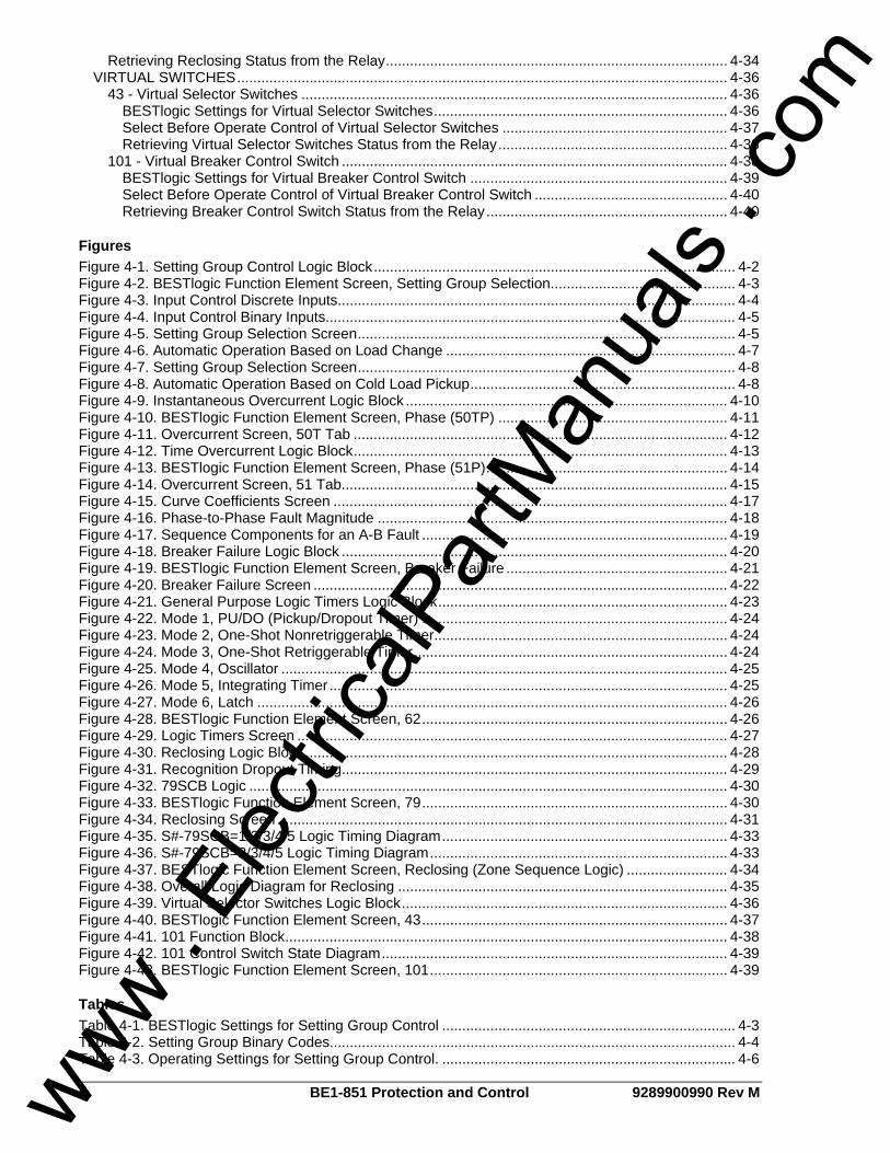
ii BE1-851 Protection and Control 9289900990 Rev M
Retrieving Reclosing Status from the Relay..................................................................................... 4-34 VIRTUAL SWITCHES.......................................................................................................................... 4-36
43 - Virtual Selector Switches .......................................................................................................... 4-36 BESTlogic Settings for Virtual Selector Switches......................................................................... 4-36 Select Before Operate Control of Virtual Selector Switches ........................................................ 4-37 Retrieving Virtual Selector Switches Status from the Relay......................................................... 4-38
101 - Virtual Breaker Control Switch ................................................................................................ 4-38 BESTlogic Settings for Virtual Breaker Control Switch ................................................................ 4-39 Select Before Operate Control of Virtual Breaker Control Switch ................................................ 4-40 Retrieving Breaker Control Switch Status from the Relay............................................................ 4-40
Figures Figure 4-1. Setting Group Control Logic Block.......................................................................................... 4-2 Figure 4-2. BESTlogic Function Element Screen, Setting Group Selection.............................................. 4-3 Figure 4-3. Input Control Discrete Inputs................................................................................................... 4-4 Figure 4-4. Input Control Binary Inputs...................................................................................................... 4-5 Figure 4-5. Setting Group Selection Screen.............................................................................................. 4-5 Figure 4-6. Automatic Operation Based on Load Change ........................................................................ 4-7 Figure 4-7. Setting Group Selection Screen.............................................................................................. 4-8 Figure 4-8. Automatic Operation Based on Cold Load Pickup.................................................................. 4-8 Figure 4-9. Instantaneous Overcurrent Logic Block ................................................................................ 4-10 Figure 4-10. BESTlogic Function Element Screen, Phase (50TP) ......................................................... 4-11 Figure 4-11. Overcurrent Screen, 50T Tab ............................................................................................. 4-12 Figure 4-12. Time Overcurrent Logic Block............................................................................................. 4-13 Figure 4-13. BESTlogic Function Element Screen, Phase (51P)............................................................ 4-14 Figure 4-14. Overcurrent Screen, 51 Tab................................................................................................ 4-15 Figure 4-15. Curve Coefficients Screen .................................................................................................. 4-17 Figure 4-16. Phase-to-Phase Fault Magnitude ....................................................................................... 4-18 Figure 4-17. Sequence Components for an A-B Fault ............................................................................ 4-19 Figure 4-18. Breaker Failure Logic Block ................................................................................................ 4-20 Figure 4-19. BESTlogic Function Element Screen, Breaker Failure ....................................................... 4-21 Figure 4-20. Breaker Failure Screen ....................................................................................................... 4-22 Figure 4-21. General Purpose Logic Timers Logic Block........................................................................ 4-23 Figure 4-22. Mode 1, PU/DO (Pickup/Dropout Timer) ............................................................................ 4-24 Figure 4-23. Mode 2, One-Shot Nonretriggerable Timer......................................................................... 4-24 Figure 4-24. Mode 3, One-Shot Retriggerable Timer.............................................................................. 4-24 Figure 4-25. Mode 4, Oscillator ............................................................................................................... 4-25 Figure 4-26. Mode 5, Integrating Timer................................................................................................... 4-25 Figure 4-27. Mode 6, Latch ..................................................................................................................... 4-26 Figure 4-28. BESTlogic Function Element Screen, 62............................................................................ 4-26 Figure 4-29. Logic Timers Screen ........................................................................................................... 4-27 Figure 4-30. Reclosing Logic Block ......................................................................................................... 4-28 Figure 4-31. Recognition Dropout Timing................................................................................................ 4-29 Figure 4-32. 79SCB Logic ....................................................................................................................... 4-30 Figure 4-33. BESTlogic Function Element Screen, 79............................................................................ 4-30 Figure 4-34. Reclosing Screen ................................................................................................................ 4-31 Figure 4-35. S#-79SCB=1/2/3/4/5 Logic Timing Diagram....................................................................... 4-33 Figure 4-36. S#-79SCB=2/3/4/5 Logic Timing Diagram.......................................................................... 4-33 Figure 4-37. BESTlogic Function Element Screen, Reclosing (Zone Sequence Logic) ......................... 4-34 Figure 4-38. Overall Logic Diagram for Reclosing .................................................................................. 4-35 Figure 4-39. Virtual Selector Switches Logic Block................................................................................. 4-36 Figure 4-40. BESTlogic Function Element Screen, 43............................................................................ 4-37 Figure 4-41. 101 Function Block.............................................................................................................. 4-38 Figure 4-42. 101 Control Switch State Diagram...................................................................................... 4-39 Figure 4-43. BESTlogic Function Element Screen, 101.......................................................................... 4-39
Tables Table 4-1. BESTlogic Settings for Setting Group Control ......................................................................... 4-3 Table 4-2. Setting Group Binary Codes..................................................................................................... 4-4 Table 4-3. Operating Settings for Setting Group Control. ......................................................................... 4-6
www . El
ectric
alPar
tMan
uals
. com
9289900990 Rev M BE1-851 Protection and Control iii
Table 4-4. BESTlogic Settings for Instantaneous Overcurrent ............................................................... 4-11 Table 4-5. Operating Settings for Instantaneous Overcurrent ................................................................ 4-13 Table 4-6. BESTlogic Settings for Time Overcurrent .............................................................................. 4-15 Table 4-7. Operating Settings for Time Overcurrent ............................................................................... 4-16 Table 4-8. Definitions for Equations 4-1 and 4-2..................................................................................... 4-17 Table 4-9. Programmable Time Current Characteristic Curve Coefficients............................................ 4-17 Table 4-10. Fault Type Multiplier ............................................................................................................. 4-19 Table 4-11. BESTlogic Settings for Breaker Failure................................................................................ 4-21 Table 4-12. Operating Settings for Breaker Failure................................................................................. 4-23 Table 4-13. BESTlogic Settings for General Purpose Logic Timers ....................................................... 4-27 Table 4-14. Operating Settings for General Purpose Logic Timers ........................................................ 4-28 Table 4-15. BESTlogic Settings for Reclosing ........................................................................................ 4-31 Table 4-16. Operating Settings for Reclosing ......................................................................................... 4-32 Table 4-17. Settings for Zone-Sequence Coordination........................................................................... 4-34 Table 4-18. BESTlogic Settings for Virtual Selector Switches ................................................................ 4-37 Table 4-19. BESTlogic Settings for Virtual Breaker Control Switch ........................................................ 4-40
Equations Equation 4-1. Time OC Characteristics for Trip ...................................................................................... 4-16 Equation 4-2. Time OC Characteristics for Reset ................................................................................... 4-16
www . El
ectric
alPar
tMan
uals
. com

iv BE1-851 Protection and Control 9289900990 Rev M
This page intentionally left blank.
www . El
ectric
alPar
tMan
uals
. com

9289900990 Rev M BE1-851 Protection and Control 4-1
SECTION 4 • PROTECTION AND CONTROL INTRODUCTION BE1-851 relays provide many functions that can be used to protect and control power system equipment in and around a protected zone. BE1-851 Type H protection functions include:
• Instantaneous Overcurrent with Settable Time Delay (50TP, 50TN, 50TQ, 150TP, 150TN, 150TQ)
• Time Overcurrent (51P, 51N, 51Q) • Breaker Failure (BF) • General Purpose Logic Timers (62, 162)
BE1-851 Type G protection functions include: • Instantaneous Overcurrent with Settable Time Delay (50TP, 150TP, 50TN, 150TN, 250TN,
350TN) • Time Overcurrent (51P, 51N, 151N) • Breaker Failure (BF) • General Purpose Logic Timers (62, 162), (262, 362 available when style option 1 is V or W.)
BE1-851 control functions include: • Reclosing (79) • Virtual Selector Switches (43, 143, 243, 343) (243, 343 not available when style option 1 is V or
W.) • Virtual Breaker Control Switches (101)
Four setting groups allow coordination to be adapted for changes in operating conditions. Setting groups can be selected using automatic or programmable logic criteria.
Using Protection and Control Functions Three steps must be taken before using a protection or control function block:
• The function block must be enabled in the active logic scheme by the SL-<function> command. • Function inputs and outputs must be connected properly in a logic scheme. • Function characteristics or settings must be programmed and based on the specific application
requirements. If a preprogrammed logic scheme is used in a typical application, the first two steps may be skipped. Most preprogrammed schemes are general in nature. Unneeded capabilities can be disabled by a setting of zero. For example, if the second negative-sequence instantaneous overcurrent function is enabled but not needed, disable it by setting the 150TQ pickup setting at zero (S#-150TQ=0). More information about the individual function blocks of item 1 is provided in this section. Information pertaining to items 2 and 3 is available in Section 7, BESTlogic Programmable Logic, and Section 8, Application.
SETTING GROUPS BE1-851 relays provide a normal setting group, SG0, and up to three auxiliary setting groups, SG1, SG2, and SG3. Auxiliary setting groups allow adapting the coordination settings to optimize them for a predictable situation. Sensitivity and time coordination settings can be adjusted to optimize sensitivity or clearing time based upon source conditions or to improve protection by eliminating compromises in coordination settings with adaptive setting groups is endless. Figure 4-1 outlines the setting group control function block. The group of settings that are active at any point in time is controlled by the setting group control function block. This function block allows for manual (logic) or automatic control. When manual control is enabled by the AUTOMATIC logic input not being asserted, the function block monitors logic inputs DO, D1, D2,
www . El
ectric
alPar
tMan
uals
. com

4-2 BE1-851 Protection and Control 9289900990 Rev M
and D3 and changes the active setting group according to the status of these inputs. These inputs can be connected to logic expressions such as contact sensing inputs. When automatic control is enabled by the AUTOMATIC logic input being asserted, the relay monitors loading or unbalance conditions and changes the active setting group according to the “switch to” and “return” criteria set. The change criteria for manual and automatic control are described in more detail later in this section.
SG0
SG1
SG3
SETTINGGROUPLOGIC
SL-GROUP
Mode0 - Disable1 - Discrete Input2 - Binary Input
SG2
P0029-1305-11-05
AUTOMATIC
D2D1
D3
D0
Figure 4-1. Setting Group Control Logic Block
The function block has four logic variable outputs, SG0, SG1, SG2, and SG3. The appropriate variable is asserted when each setting group is active. These logic variables can be used in programmable logic to modify the logic based upon which setting group is active. For example, it may be desired for the 51P to trip the low side breaker through OUT2 under normal conditions but to trip the 86T lockout relay through OUT1 only when in setting group 3. The logic for OUT1 would include the term 51PT*SG3 so that 51PT only actuates OUT1 when SG3 is asserted. The setting group control function block also has an alarm output variable SGC (Setting Group Changed). This output is asserted whenever the relay switches from one setting group to another. The SGC alarm bit is asserted for the SGCON time setting. This output can be used in the programmable alarms function if it is desired to monitor when the relay changes to a new setting group. See Section 6, Reporting and Alarm Functions, Alarms Function, for more information on using alarm outputs. The SGCON time setting also serves to provide anti-pump protection to prevent excessive changing between groups. Once a change in active group has been made, another change cannot take place for two times the SGCON setting. The SGC ACTIVE alarm output is typically used to provide an external acknowledgment that a setting group change occurred. If SCADA is used to change the active group, then this signal could be monitored to verify that the operation occurred. The SGC ACTIVE alarm output ON time is user programmable and should be set greater than the SCADA scan rate. This can be set through the ASCII command interface by using the SG-SGCON (settings general – SGC Alarm on time) command. When the relay switches to a new setting group, all functions are reset and initialized with the new operating parameters. This settings change occurs instantaneously so at no time is the relay off line. The active setting group is saved in non-volatile memory so that the relay will power up using the same setting group as it was using when it was powered down. To prevent the relay from changing settings while a fault condition is in process, setting group changes are blocked when the relay is in a picked-up state. Since the relay is completely programmable, the fault condition is defined by the pickup logic expression in the fault reporting functions. See Section 6, Reporting and Alarm Functions, Fault Reporting, for more information. The selection of the active setting group provided by this function block can also be overridden. When the logic override is used, a setting group is made active and the relay stays in that group regardless of the state of the automatic or manual logic control conditions.
BESTlogic Settings for Setting Group Control BESTlogic settings are made from the BESTlogic Function Element screen in BESTCOMS. Figure 4-2 illustrates the BESTCOMS screen used to select BESTlogic settings for the Setting Group Control function. To open the BESTlogic Function Element screen for Setting Group Selection, select Setting Group Selection from the Screens pull-down menu. Then select the BESTlogic button in the lower left hand corner of the screen. Alternately, settings may be made through the ASCII command interface using the SL-GROUP (settings logic-group control) command.
www . El
ectric
alPar
tMan
uals
. com
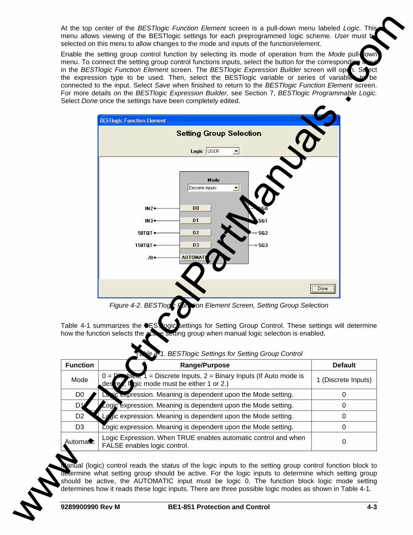
9289900990 Rev M BE1-851 Protection and Control 4-3
At the top center of the BESTlogic Function Element screen is a pull-down menu labeled Logic. This menu allows viewing of the BESTlogic settings for each preprogrammed logic scheme. User must be selected on this menu to allow changes to the mode and inputs of the function/element. Enable the setting group control function by selecting its mode of operation from the Mode pull-down menu. To connect the setting group control functions inputs, select the button for the corresponding input in the BESTlogic Function Element screen. The BESTlogic Expression Builder screen will open. Select the expression type to be used. Then, select the BESTlogic variable or series of variables to be connected to the input. Select Save when finished to return to the BESTlogic Function Element screen. For more details on the BESTlogic Expression Builder, see Section 7, BESTlogic Programmable Logic. Select Done once the settings have been completely edited.
Figure 4-2. BESTlogic Function Element Screen, Setting Group Selection
Table 4-1 summarizes the BESTlogic settings for Setting Group Control. These settings will determine how the function selects the active setting group when manual logic selection is enabled.
Table 4-1. BESTlogic Settings for Setting Group Control
Function Range/Purpose Default
Mode 0 = Disabled, 1 = Discrete Inputs, 2 = Binary Inputs (If Auto mode is desired, logic mode must be either 1 or 2.) 1 (Discrete Inputs)
D0 Logic expression. Meaning is dependent upon the Mode setting. 0 D1 Logic expression. Meaning is dependent upon the Mode setting. 0 D2 Logic expression. Meaning is dependent upon the Mode setting. 0 D3 Logic expression. Meaning is dependent upon the Mode setting. 0
Automatic Logic Expression. When TRUE enables automatic control and when FALSE enables logic control. 0
Manual (logic) control reads the status of the logic inputs to the setting group control function block to determine what setting group should be active. For the logic inputs to determine which setting group should be active, the AUTOMATIC input must be logic 0. The function block logic mode setting determines how it reads these logic inputs. There are three possible logic modes as shown in Table 4-1.
www . El
ectric
alPar
tMan
uals
. com

4-4 BE1-851 Protection and Control 9289900990 Rev M
When the setting group control function block is enabled for Discrete Inputs, there is a direct correspondence between each discrete logic input and the setting group that will be selected. That is, when input D0 is asserted, SG0 will be selected, and when input D1 is asserted SG1 will be selected, etc. The active setting group latches in after the input is read so they can be pulsed. It is not necessary that the input be maintained. If one or more inputs are asserted at the same time, the numerically higher setting group will be the active one. A pulse must be present for approximately one second for the setting group change to occur. After a setting group change occurs, no setting group change can occur within two times the SGC alarm-on time. Any pulses to the inputs will be ignored during that period. Figure 4-3 shows an example of how the inputs are read when the setting group control function block is enabled for Discrete Inputs. Note that a pulse on the D3 input while D0 was also active does not cause a setting group change to SG3 because the AUTO input is active.
D3
D2
D1
D0
AUTO
SG3
SG2
SG1
SG0
SGC
D2647-2008-21-98
Figure 4-3. Input Control Discrete Inputs
When the setting group control function block is enabled for Binary Inputs, the inputs on D0 and D1 are read as binary encoded as shown in Table 4-2. Inputs D2 and D3 are ignored. A new coded input must be stable for approximately 1 second for the setting group change to occur. After a setting group change occurs, no setting group change can occur within two times the SGC alarm on time.
Table 4-2. Setting Group Binary Codes
Binary Code D1 D0
Decimal Equivalent Setting Group
0 0 0 SG0 0 1 1 SG1 1 0 2 SG2 1 1 3 SG3
When using control mode 2, the active setting group is controlled by a binary signal applied to the discrete inputs D0-D1. This requires separate logic equations for only D0 and D1 if all setting groups are to be used. Figure 4-4 shows how the active setting group follows the binary sum of the D0 and D1 inputs except when blocked by the AUTO input. Note that a pulse on the D1 input while D0 was also active does not cause a setting group change to SG3 because the AUTO input is active. Figure 4-4 shows an example of how the inputs are read when the setting group control function block is enabled for Binary Inputs. Note that a pulse on the D1 input while D0 was also active does not cause a setting group change to SG3 because the Auto input is active.
www . El
ectric
alPar
tMan
uals
. com
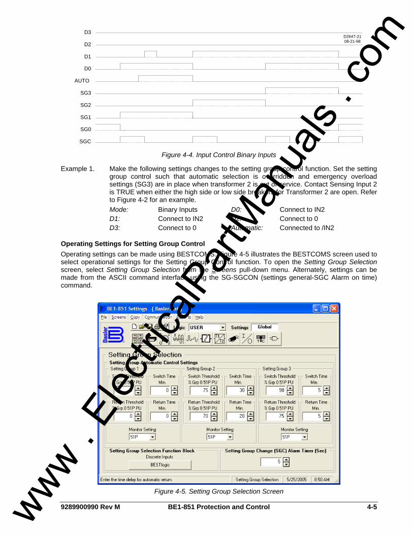
9289900990 Rev M BE1-851 Protection and Control 4-5
D2647-2108-21-98
D3
D2
D1
D0
AUTO
SG3
SG2
SG1
SG0
SGC
Figure 4-4. Input Control Binary Inputs
Example 1. Make the following settings changes to the setting group control function. Set the setting group control such that automatic selection is overridden and emergency overload settings (SG3) are in place when transformer 2 is out of service. Contact Sensing Input 2 is TRUE when either the high side or low side breakers for Transformer 2 are open. Refer to Figure 4-2 for an example.
Mode: Binary Inputs D0: Connect to IN2 D1: Connect to IN2 D2: Connect to 0 D3: Connect to 0 Automatic: Connected to /IN2
Operating Settings for Setting Group Control Operating settings can be made using BESTCOMS. Figure 4-5 illustrates the BESTCOMS screen used to select operational settings for the Setting Group Control function. To open the Setting Group Selection screen, select Setting Group Selection from the Screens pull-down menu. Alternately, settings can be made from the ASCII command interface using the SG-SGCON (settings general-SGC Alarm on time) command.
Figure 4-5. Setting Group Selection Screen
www . El
ectric
alPar
tMan
uals
. com

4-6 BE1-851 Protection and Control 9289900990 Rev M
At the top center of the screen is a pull-down menu labeled Logic. This menu allows viewing of the BESTlogic settings for each preprogrammed logic scheme. Using the pull-down menus and buttons, make the application-appropriate settings to the Setting Group Control function. Table 4-3 summarizes the operating settings for Setting Group Control.
Table 4-3. Operating Settings for Setting Group Control.
Setting Range Increment Unit of Measure Default Switch Threshold 0 – 150 1 % of SG0 51* Pickup 0 Switch Time 0 = Disabled, 1 – 60 1 Minutes 0 Return Threshold 0 – 150 1 % of SG0 51* Pickup 0 Return Time 0 = Disabled, 1 – 60 1 Minutes 0 Monitored Element See Note N/A N/A 51P Setting Group Change (SGC) Alarm Timer 0 = Disabled, 1 - 10 1 Seconds 5
The SGC alarm output (SGC ACTIVE) is typically used to provide an external acknowledgement that a setting group change occurred. If SCADA was used to change the active group, then this signal could be monitored to verify that the operation occurred. The SGC ACTIVE alarm output ON time is user programmable using the Setting Group Change (SGC) Alarm Timer (sec.) setting on the BESTCOMS screen (refer to Figure 4-5). The setting should be set greater than the SCADA scan rate. Example 1. Set the SGC alarm timer to 5 seconds. Refer to Figure 4-5. Setting Group Change (SGC) Alarm timer (sec.): 5 Automatic control of the active setting group allows the relay to automatically change configuration for optimum protection based on the current system conditions. For example, in locations where seasonal variations can cause large variations in loading, the overcurrent protection can be set with sensitive settings during the majority of the time and switch to a setting group with lower sensitivity (higher pickups) during the few days of the year when the loading is at peak. There are five settings for each group that are used for automatic control. Each group has a switch to threshold and time delay, a return threshold and time delay, and a monitored element. The switch to and return thresholds are a percentage of the SG0 pickup setting for the monitored element. The monitored element can be any of the 51 protective functions. Thus, if you wish to switch settings based upon loading, you could set it to monitor 51P. If you with to switch settings based upon unbalance, you could set it to monitor 51N or 51Q. When the monitored element is 51P, any one phase must be above the switch to threshold for the switch to time delay for the criteria to be met. All phases must be below the return threshold for the return time delay for the return criteria to be met. Figure 4-6 shows an example of using the automatic setting group selection settings to change setting groups based upon loading. Figure 4-5 illustrates the operating settings used in the diagram shown in Figure 4-6. Note that the AUTO input must be at a TRUE logic state in order to allow the automatic logic to operate. At time = 0, current begins to increase. When current reaches 75 percent of pickup, setting group two begins timing (30 minutes). When current reaches 90 percent of pickup, setting group three begins timing (5 minutes). After 5 minutes, at time = 37, with the current still above setting group three threshold, setting group three becomes active and the setting group change output pulses. At time = 55, setting group two timer times out but no setting group change occurs because a higher setting group takes precedence. The faint dashed line for SG2, between time = 55 and 75 shows that setting group two would be active except for setting group three. Current decreases to 75 percent at time = 70 and setting
NOTE Monitored element for sensing input type H is any 51 element: 51P, 51N, 51Q, 791, 792, 793, and 794. Monitored element for Sensing Input Type G is any 51 element: 51P, 51N, 151N, 791, 792, 793, and 794.
www . El
ectric
alPar
tMan
uals
. com

9289900990 Rev M BE1-851 Protection and Control 4-7
group three return timer begins timing. Current varies but stays below 75 percent for 5 minutes and at time = 75, setting group two becomes active and the setting change output pulses. After 20 minutes, setting group zero becomes active and the setting change output pulses.
Load Currentas % of S0-51 <pickup>
090
80
70
60
50
40
30
20
10
100
40
30
20
10
100
90
80
70
60
50
120
110
140
130
150
TIME(MINUTES)
305
20
5
SP-GROUP3=5,90,5,75,51P
SP-GROUP2=30,75,20,70,51P
SG3
SG2
SG1
SG0
SGCD2837-23.vsd
01-07-99
Figure 4-6. Automatic Operation Based on Load Change
This function can also be used to automatically change the active setting group for cold load pickup conditions. If the switch to threshold for a group is set to 0%, the function will switch to that group when there is no current flow for the time delay period indicating that the breaker is open or the circuit source is out of service. The threshold for this is 10% nominal rating of the relay current input. Figure 4-8 shows how the active setting group follows the load current and time delay settings. Figure 4-7 illustrates the operating settings used in the diagram shown in Figure 4-8. Note that the AUTO input must be at a TRUE (1) logic state for the automatic logic to operate. When the breaker opens, the load current falls to zero, time = 15 minutes. After 10 minutes, setting group one becomes active and the setting group change output pulses TRUE. When the breaker is closed, time = 40 minutes, load current increases to approximately 90 percent of pickup. As the load current decreases to 50 percent of pickup, the setting group one return timer begins timing. After ten minutes, setting group one output goes FALSE, the setting group returns to setting group zero, and the setting group change output pulses TRUE. When the switch to criteria is met for more than one setting group at a time, the function will use the numerically higher of the enabled setting groups. If the switch to time delay setting is set to 0 for a setting group, automatic control for that group is disabled. If the return time delay setting is set to 0 for a setting group, automatic return for that group is disabled and the relay will remain in that setting group until returned manually by logic override control.
www . El
ectric
alPar
tMan
uals
. com
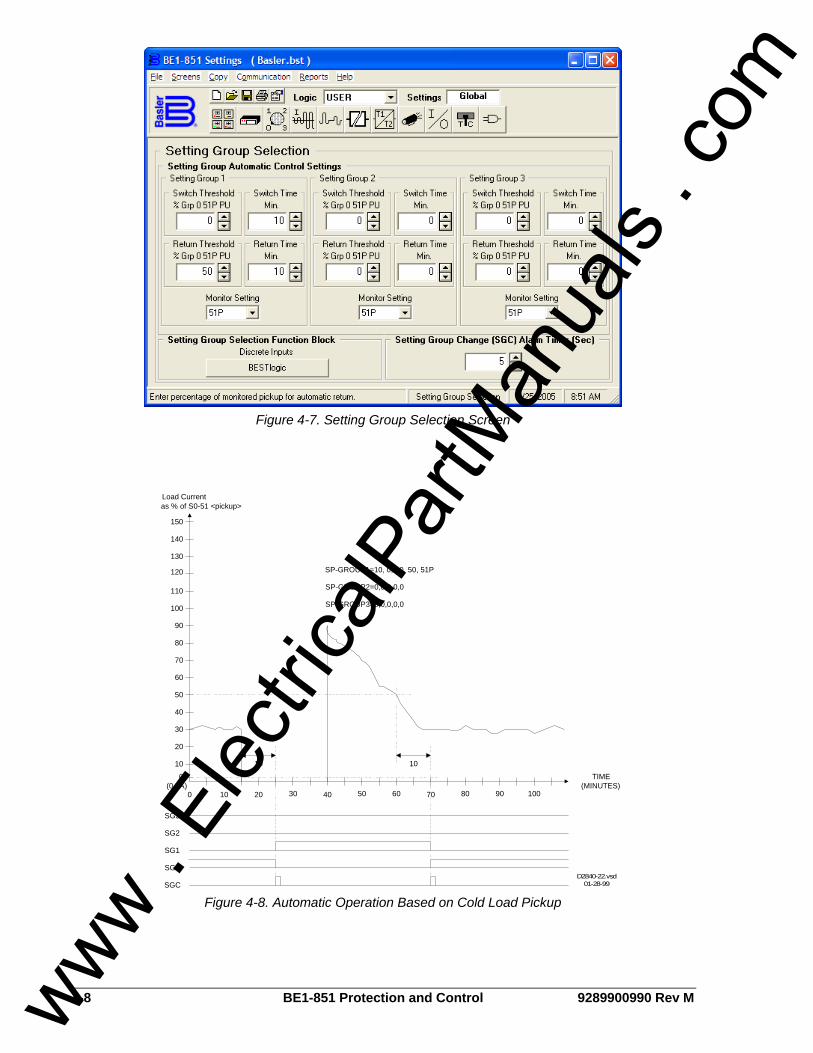
4-8 BE1-851 Protection and Control 9289900990 Rev M
Figure 4-7. Setting Group Selection Screen
SG3
SG2
SG1
SG0
SGC
Load Currentas % of S0-51 <pickup>
40
30
20
10
100
90
80
70
60
50
120
110
140
130
150
SP-GROUP1=10, 0, 10, 50, 51P
10 10
SP-GROUP3=0,0,0,0,0
SP-GROUP2=0,0,0,0,0
0 908070605040302010 100
TIME(MINUTES)
0(0.5A)
D2840-22.vsd01-28-99
Figure 4-8. Automatic Operation Based on Cold Load Pickup
www . El
ectric
alPar
tMan
uals
. com

9289900990 Rev M BE1-851 Protection and Control 4-9
Logic Override of the Setting Group Control Function Control of the active setting group from the setting group control function can be overridden. This can be accomplished from the HMI Screen 2.3.1, \CONTROL\SETTING GROUP CONTROL\SET GROUP LOGIC OVERRIDE or from the ASCII command interface using the select before operate CS/CO-GROUP (control select-setting group/control operate-setting group) command. This cannot be done using BESTCOMS. A setting group change using logic override control is also blocked for two times the SGC on setting after a setting group change and when the fault reporting pickup expression is TRUE. The setting group change takes place immediately without having to execute an EXIT – SAVE setting command. A group override alarm bit is set in the programmable alarm function when the logic has been overridden. This output can be used in the programmable alarms function if it is desired to monitor when the function has been overridden. See Section 6, Reporting and Alarm Functions, Alarms Function, for more information on using alarm outputs. The group control commands require the use of Select before Operate logic. First the command must be selected using the CS-GROUP command. After the command is selected there is a 30 second window during which the CO-GROUP control command can be entered. The control selected and operation selected must exactly match or the command is blocked. If the command is not entered within the 30-second window, the command is blocked. If the control command is blocked, an error message is output. Example 1. Read the current status of setting group override that is overridden and held in SG0. >CO-GROUP 0
Example 2. Override logic control and change the active setting group to SG3. >CS-GROUP=3 GROUP=3 SELECTED >CO-GROUP=3 GROUP=3 EXECUTED
Example 3. Return control of the active setting group to the setting group control function. >CS-GROUP=L GROUP=L SELECTED >CO-GROUP=L GROUP=L EXECUTED
Example 4. Group override error due to time out of select. >CS-GROUP=3 GROUP=3 SELECTED >CO-GROUP=3 ERROR:NO SELECT ?
Retrieving Setting Group Control Status from the Relay The active setting group can be determined from the HMI Screen 1.5.5, \REPORT STATUS\OPERATIONAL STATUS\ACTIVE GROUP. The setting group can be determined from the ASCII command interface using the RG-STAT command. It cannot be determined using BESTCOMS. See Section 6, Reporting and Alarm Functions, General Status Reporting, for more information. The status of logic override can be determined from the HMI Screen 2.3.1, \CONTROL\SETTING GROUP CONTROL\SET GROUP LOGIC OVERRIDE. The status of logic override can be determined from the ASCII command interface using the RG-STAT command. See Section 6, Reporting and Alarm Functions, General Status Reporting, for more information.
www . El
ectric
alPar
tMan
uals
. com

4-10 BE1-851 Protection and Control 9289900990 Rev M
OVERCURRENT PROTECTION BE1-851 overcurrent protection includes instantaneous elements for Phase, Neutral, and Negative-Sequence, as well as time overcurrent elements for Phase, Neutral, and Negative-Sequence.
50T - Instantaneous Overcurrent Protection with Settable Time Delay There are two independent BESTlogic function blocks for phase (50TP, 150TP), two for neutral (50TN, 150TN), and two for negative-sequence (50TQ, 150TQ) instantaneous overcurrent protection. Sensing input type G relays have four neutral elements and two phase elements. Sensing input type H units have two neutral, two phase, and two negative-sequence elements. The BESTlogic mode setting can connect each function block to any of the CT inputs. The instantaneous overcurrent functions are labeled 50T and 150T because each function has an adjustable time delay. If a function block has a time delay setting of zero, then that function block will operate as an instantaneous overcurrent relay. Each of the six independent function blocks has two logic outputs, pickup, and trip. A T at the end of its label indicates the trip output and a PU indicates pickup. The first letter of the label indicates the element type where P is a phase element, N is a neutral element, and Q is a negative-sequence element. The 50T element illustrated in Figure 4-9 is a phase element.
Figure 4-9. Instantaneous Overcurrent Logic Block
Each function block has a Block input that can be used to disable the function. A BESTlogic expression is used to define the Block input. When this expression is TRUE, forcing the outputs to logic zero and resetting the timers to zero disable the function block. This feature functions in a similar way to the torque control contact of an electro-mechanical relay. A logic mode input allows each instantaneous overcurrent function block to be enabled or disabled. More information about logic mode selection is provided in the following paragraph titled BESTlogic Settings for Instantaneous Overcurrent paragraph. Each instantaneous overcurrent function has a pickup and time delay setting. When the measured current increases above the pickup threshold, the pickup output (x50TPPU) becomes TRUE and the timer starts. If the current stays above pickup for the duration of the time delay setting, the trip output (x50TPT) becomes TRUE. If the current decreases below the dropout ratio, which is 95 percent of pickup, the timer is reset to zero (¼ to ½ cycles later). The phase overcurrent protective functions include three independent comparators and timers, one for each phase. If the current increases above the pickup setting for any one phase, the pickup output asserts. If the trip condition is TRUE for any one phase, the trip logic output asserts. If the target is enabled for the function block, the target reporting function will record a target for the appropriate phase when the protective function trip output is TRUE and the fault recording function trip logic expression is TRUE. See Section 6, Reporting and Alarm Functions, Fault Reporting, for more information about target reporting.
BESTlogic Settings for Instantaneous Overcurrent BESTlogic settings are made from the BESTlogic Function Element screen in BESTCOMS. Figure 4-10 illustrates the BESTCOMS screen used to select BESTlogic settings for the Instantaneous Overcurrent element. To open the BESTlogic Function Element screen for Instantaneous Overcurrent with Settable Time Delay, select Overcurrent from the Screens pull-down menu and select either the 50T or 150T tab. Then select the BESTlogic button for the element you wish to edit. Alternately, logic settings for the 50T and 150T functions can be made using the SL-x50T ASCII command.
www . El
ectric
alPar
tMan
uals
. com
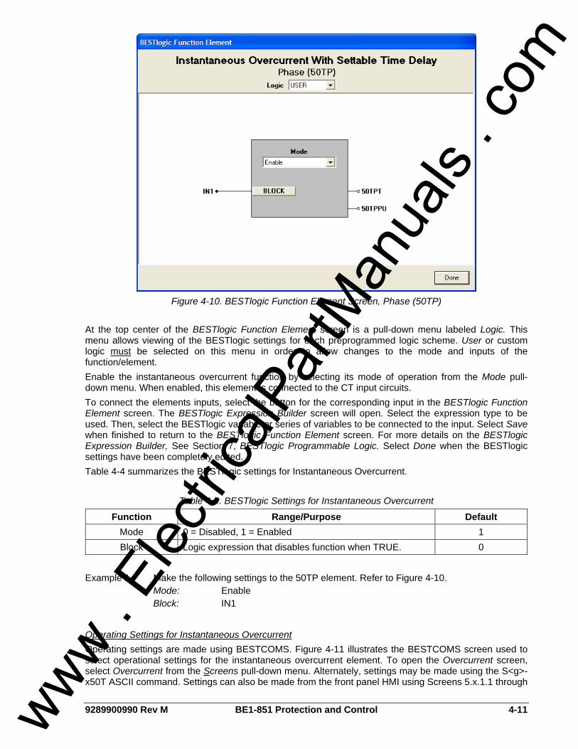
9289900990 Rev M BE1-851 Protection and Control 4-11
Figure 4-10. BESTlogic Function Element Screen, Phase (50TP)
At the top center of the BESTlogic Function Element screen is a pull-down menu labeled Logic. This menu allows viewing of the BESTlogic settings for each preprogrammed logic scheme. User or custom logic must be selected on this menu in order to allow changes to the mode and inputs of the function/element. Enable the instantaneous overcurrent function by selecting its mode of operation from the Mode pull-down menu. When enabled, this element is connected to the CT input circuits. To connect the elements inputs, select the button for the corresponding input in the BESTlogic Function Element screen. The BESTlogic Expression Builder screen will open. Select the expression type to be used. Then, select the BESTlogic variable or series of variables to be connected to the input. Select Save when finished to return to the BESTlogic Function Element screen. For more details on the BESTlogic Expression Builder, See Section 7, BESTlogic Programmable Logic. Select Done when the BESTlogic settings have been completely edited. Table 4-4 summarizes the BESTlogic settings for Instantaneous Overcurrent.
Table 4-4. BESTlogic Settings for Instantaneous Overcurrent
Function Range/Purpose Default Mode 0 = Disabled, 1 = Enabled 1 Block Logic expression that disables function when TRUE. 0
Example 1. Make the following settings to the 50TP element. Refer to Figure 4-10. Mode: Enable Block: IN1
Operating Settings for Instantaneous Overcurrent Operating settings are made using BESTCOMS. Figure 4-11 illustrates the BESTCOMS screen used to select operational settings for the instantaneous overcurrent element. To open the Overcurrent screen, select Overcurrent from the Screens pull-down menu. Alternately, settings may be made using the S<g>-x50T ASCII command. Settings can also be made from the front panel HMI using Screens 5.x.1.1 through
www . El
ectric
alPar
tMan
uals
. com
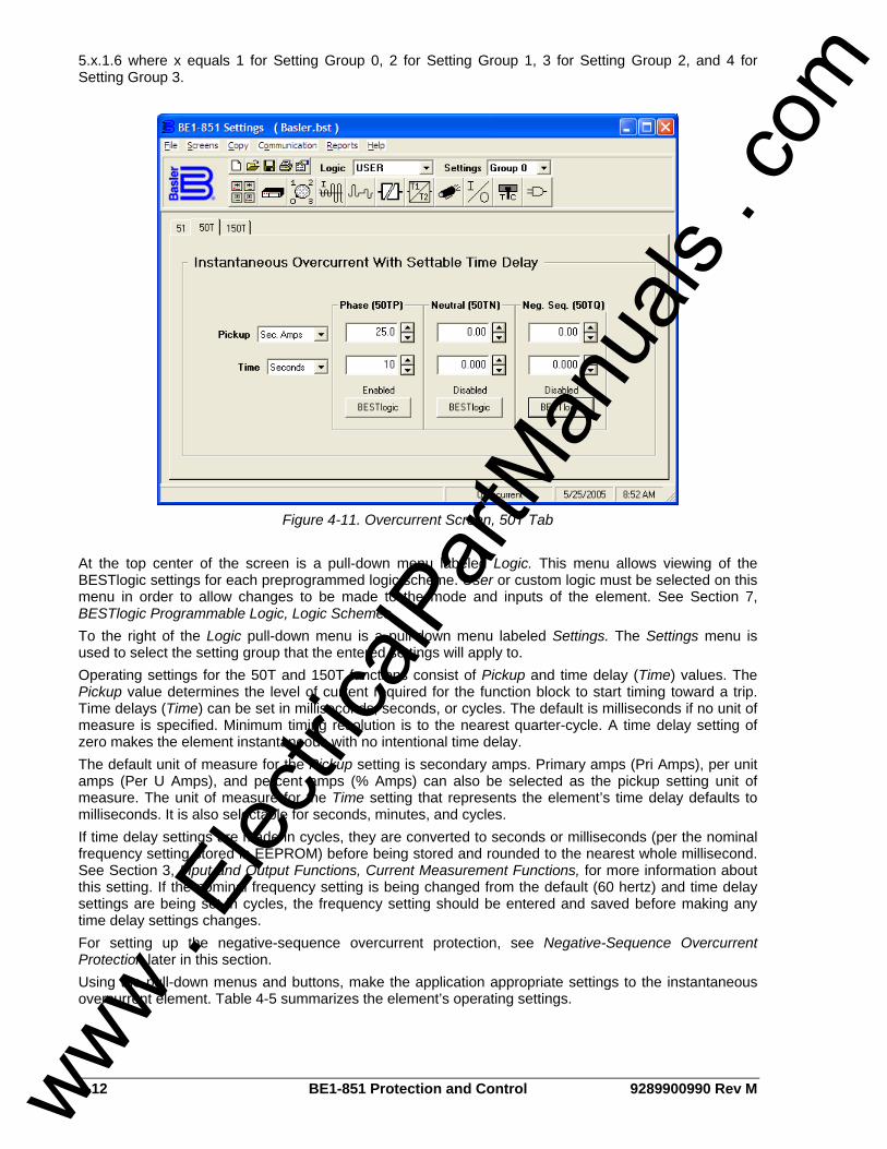
4-12 BE1-851 Protection and Control 9289900990 Rev M
5.x.1.6 where x equals 1 for Setting Group 0, 2 for Setting Group 1, 3 for Setting Group 2, and 4 for Setting Group 3.
Figure 4-11. Overcurrent Screen, 50T Tab
At the top center of the screen is a pull-down menu labeled Logic. This menu allows viewing of the BESTlogic settings for each preprogrammed logic scheme. User or custom logic must be selected on this menu in order to allow changes to be made to the mode and inputs of the element. See Section 7, BESTlogic Programmable Logic, Logic Schemes. To the right of the Logic pull-down menu is a pull-down menu labeled Settings. The Settings menu is used to select the setting group that the entered settings will apply to. Operating settings for the 50T and 150T functions consist of Pickup and time delay (Time) values. The Pickup value determines the level of current required for the function block to start timing toward a trip. Time delays (Time) can be set in milliseconds, seconds, or cycles. The default is milliseconds if no unit of measure is specified. Minimum timing resolution is to the nearest quarter-cycle. A time delay setting of zero makes the element instantaneous with no intentional time delay. The default unit of measure for the Pickup setting is secondary amps. Primary amps (Pri Amps), per unit amps (Per U Amps), and percent amps (% Amps) can also be selected as the pickup setting unit of measure. The unit of measure for the Time setting that represents the element’s time delay defaults to milliseconds. It is also selectable for seconds, minutes, and cycles. If time delay settings are made in cycles, they are converted to seconds or milliseconds (per the nominal frequency setting stored in EEPROM) before being stored and rounded to the nearest whole millisecond. See Section 3, Input and Output Functions, Current Measurement Functions, for more information about this setting. If the nominal frequency setting is being changed from the default (60 hertz) and time delay settings are being set in cycles, the frequency setting should be entered and saved before making any time delay settings changes. For setting up the negative-sequence overcurrent protection, see Negative-Sequence Overcurrent Protection later in this section. Using the pull-down menus and buttons, make the application appropriate settings to the instantaneous overcurrent element. Table 4-5 summarizes the element’s operating settings.
www . El
ectric
alPar
tMan
uals
. com
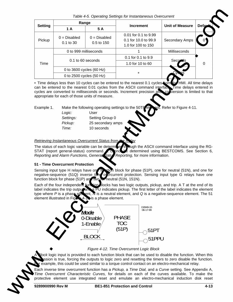
9289900990 Rev M BE1-851 Protection and Control 4-13
Table 4-5. Operating Settings for Instantaneous Overcurrent
Range Setting
1 A 5 A Increment Unit of Measure Default
Pickup 0 = Disabled
0.1 to 30 0 = Disabled
0.5 to 150
0.01 for 0.1 to 9.99 0.1 for 10.0 to 99.9 1.0 for 100 to 150
Secondary Amps 0
0 to 999 milliseconds 1 Milliseconds 0.1 for 0.1 to 9.9
0.1 to 60 seconds 1.0 for 10 to 60
Seconds
0 to 3600 cycles (60 Hz) Time
0 to 2500 cycles (50 Hz) ∗ Cycles
0
∗ Time delays less than 10 cycles can be entered to the nearest 0.1 cycles from the HMI. All time delays can be entered to the nearest 0.01 cycles from the ASCII command interface. Time delays entered in cycles are converted to milliseconds or seconds. Increment precision after conversion is limited to that appropriate for each of those units of measure. Example 1. Make the following operating settings to the 50TP element. Refer to Figure 4-11. Logic: User Settings: Setting Group 0 Pickup: 25 secondary amps Time: 10 seconds
Retrieving Instantaneous Overcurrent Status from the Relay The status of each logic variable can be determined through the ASCII command interface using the RG-STAT (report general-status) command. It cannot be determined using BESTCOMS. See Section 6, Reporting and Alarm Functions, General Status Reporting, for more information.
51 - Time Overcurrent Protection Sensing input type H relays have one function block for phase (51P), one for neutral (51N), and one for negative-sequence (51Q) inverse time overcurrent protection. Sensing input type G relays have one function block for phase (51P) and two for neutral (51N, 151N). Each of the four independent function blocks has two logic outputs, pickup, and trip. A T at the end of its label indicates the trip output and a PU indicates pickup. The first letter of the label indicates the element type where P is a phase element, N is a neutral element, and Q is a negative-sequence element. The 51 element illustrated in Figure 4-12 is a phase element.
BLOCK51PT
51PPU
Mode0-Disable1-Enable
PHASETOC(51P)
D2849-1506-17-99
Figure 4-12. Time Overcurrent Logic Block
A Block logic input is provided to each function block that can be used to disable the function. When this expression is true, forcing the outputs to logic zero and resetting the timers to zero disable the function. For example, this could be used similar to a torque control contact on an electro-mechanical relay. Each inverse time overcurrent function has a Pickup, a Time Dial, and a Curve setting. See Appendix A, Time Overcurrent Characteristic Curves, for details on each of the curves available. To make the protective element use integrated reset and emulate an electro-mechanical induction disk reset
www . El
ectric
alPar
tMan
uals
. com
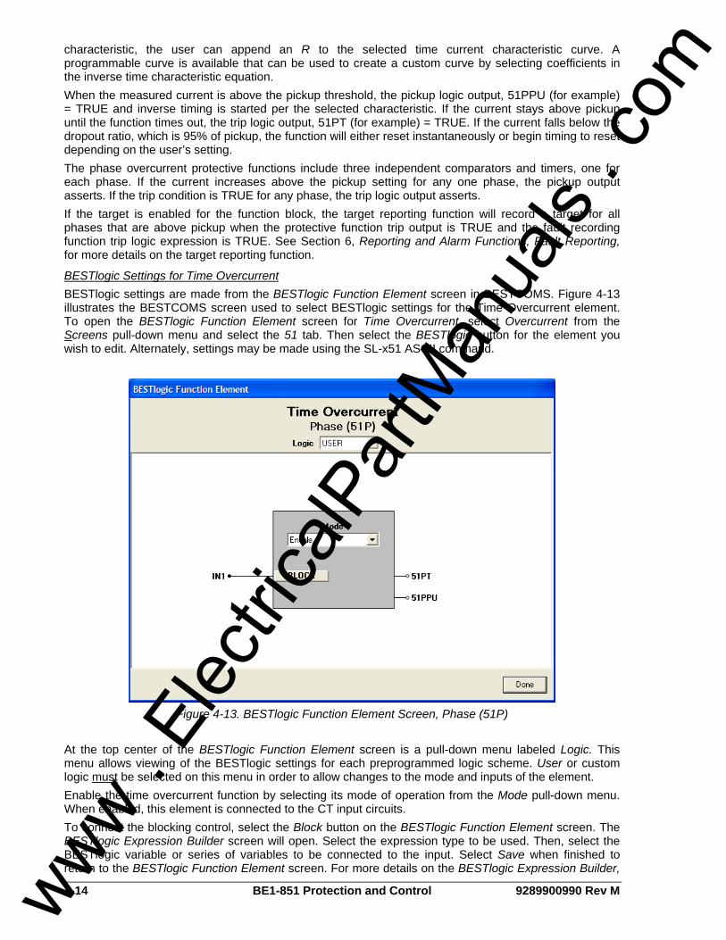
4-14 BE1-851 Protection and Control 9289900990 Rev M
characteristic, the user can append an R to the selected time current characteristic curve. A programmable curve is available that can be used to create a custom curve by selecting coefficients in the inverse time characteristic equation. When the measured current is above the pickup threshold, the pickup logic output, 51PPU (for example) = TRUE and inverse timing is started per the selected characteristic. If the current stays above pickup until the function times out, the trip logic output, 51PT (for example) = TRUE. If the current falls below the dropout ratio, which is 95% of pickup, the function will either reset instantaneously or begin timing to reset depending on the user’s setting. The phase overcurrent protective functions include three independent comparators and timers, one for each phase. If the current increases above the pickup setting for any one phase, the pickup output asserts. If the trip condition is TRUE for any phase, the trip logic output asserts. If the target is enabled for the function block, the target reporting function will record a target for all phases that are above pickup when the protective function trip output is TRUE and the fault recording function trip logic expression is TRUE. See Section 6, Reporting and Alarm Functions, Fault Reporting, for more details on the target reporting function.
BESTlogic Settings for Time Overcurrent BESTlogic settings are made from the BESTlogic Function Element screen in BESTCOMS. Figure 4-13 illustrates the BESTCOMS screen used to select BESTlogic settings for the Time Overcurrent element. To open the BESTlogic Function Element screen for Time Overcurrent, select Overcurrent from the Screens pull-down menu and select the 51 tab. Then select the BESTlogic button for the element you wish to edit. Alternately, settings may be made using the SL-x51 ASCII command.
Figure 4-13. BESTlogic Function Element Screen, Phase (51P)
At the top center of the BESTlogic Function Element screen is a pull-down menu labeled Logic. This menu allows viewing of the BESTlogic settings for each preprogrammed logic scheme. User or custom logic must be selected on this menu in order to allow changes to the mode and inputs of the element. Enable the time overcurrent function by selecting its mode of operation from the Mode pull-down menu. When enabled, this element is connected to the CT input circuits. To connect the blocking control, select the Block button on the BESTlogic Function Element screen. The BESTlogic Expression Builder screen will open. Select the expression type to be used. Then, select the BESTlogic variable or series of variables to be connected to the input. Select Save when finished to return to the BESTlogic Function Element screen. For more details on the BESTlogic Expression Builder,
www . El
ectric
alPar
tMan
uals
. com
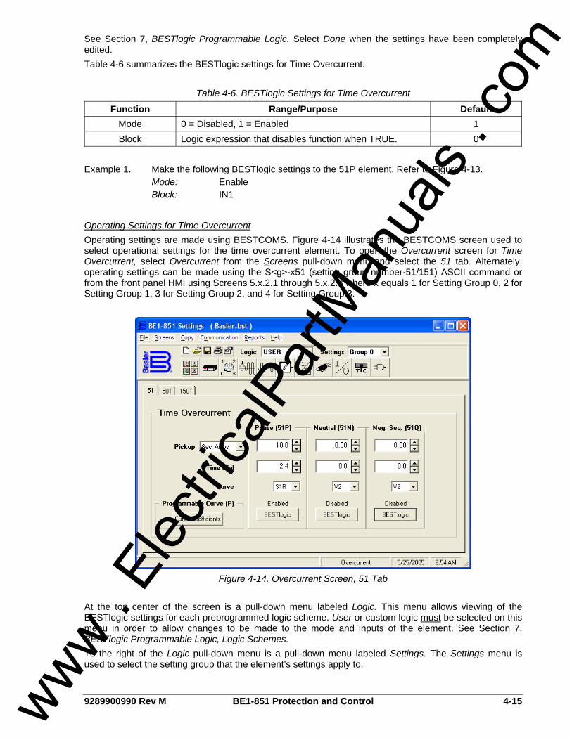
9289900990 Rev M BE1-851 Protection and Control 4-15
See Section 7, BESTlogic Programmable Logic. Select Done when the settings have been completely edited. Table 4-6 summarizes the BESTlogic settings for Time Overcurrent.
Table 4-6. BESTlogic Settings for Time Overcurrent
Function Range/Purpose Default Mode 0 = Disabled, 1 = Enabled 1 Block Logic expression that disables function when TRUE. 0
Example 1. Make the following BESTlogic settings to the 51P element. Refer to Figure 4-13. Mode: Enable Block: IN1
Operating Settings for Time Overcurrent Operating settings are made using BESTCOMS. Figure 4-14 illustrates the BESTCOMS screen used to select operational settings for the time overcurrent element. To open the Overcurrent screen for Time Overcurrent, select Overcurrent from the Screens pull-down menu and select the 51 tab. Alternately, operating settings can be made using the S<g>-x51 (setting group number-51/151) ASCII command or from the front panel HMI using Screens 5.x.2.1 through 5.x.2.3 where x equals 1 for Setting Group 0, 2 for Setting Group 1, 3 for Setting Group 2, and 4 for Setting Group 3.
Figure 4-14. Overcurrent Screen, 51 Tab
At the top center of the screen is a pull-down menu labeled Logic. This menu allows viewing of the BESTlogic settings for each preprogrammed logic scheme. User or custom logic must be selected on this menu in order to allow changes to be made to the mode and inputs of the element. See Section 7, BESTlogic Programmable Logic, Logic Schemes. To the right of the Logic pull-down menu is a pull-down menu labeled Settings. The Settings menu is used to select the setting group that the element’s settings apply to.
www . El
ectric
alPar
tMan
uals
. com

4-16 BE1-851 Protection and Control 9289900990 Rev M
The pickup value determines the level of current required for the element to start timing toward a trip. Time Dial is used to select the time delay between pickup and trip based on the selected Curve. See Appendix A, Time Overcurrent Characteristic Curves. The unit of measure for the Pickup setting defaults to secondary amps though it is selectable for primary amps (Pri Amps), per unit amps (Per U Amps), and percent amps (% Amps). Using the pull-down menus and buttons, make the application appropriate settings to the time overcurrent element. Table 4-7 summarizes the operating settings for Time Overcurrent.
Table 4-7. Operating Settings for Time Overcurrent
Range Setting
1 A 5 A Increment Unit of Measure Default
Pickup 0 = Disabled
0.1 to 3.2 0 = Disabled
0.5 to 16 0.01 for 0.1 to 9.99 0.1 for 10.0 to 16.0
Secondary Amps 0
Time Dial 0.0 to 9.9 0.1 N/A 0 Curve See Appendix A, Table A-1 N/A N/A V2
Example 1. Make the following operating settings to the 51P element. Refer to Figure 4-15. Logic: User Settings: Setting Group 0 Pickup: 10 secondary amps Time Dial: 2.4 Curve: S1R
Setting Programmable Time Current Characteristic Curve Coefficients Equation 4-1 and Equation 4-2 define time current characteristics for trip and reset respectively. These equations comply with IEEE standard C37.112-1996. The curve specific coefficients are defined for the standard curves as listed in Appendix A, Time Overcurrent Characteristic Curves. Standard curves can be selected for each 51 or 151 protection element by selecting them from the desired elements Curve pull-down menu. When time current characteristic curve P is selected, the coefficients used in the equation are those defined by the user. Definitions for these equations are provided in Table 4-8.
Equation 4-1. Time OC Characteristics for Trip
KBDCM
ADTNT ++−
=
Equation 4-2. Time OC Characteristics for Reset
12 −=
MRDTR
NOTE Changing settings while the relay is in service will return an error message (PU CONDITON) if the new setting is within approximately 90 percent of the metered current level. This is intended to prevent the user from inadvertently causing a trip when changing a setting.
www . El
ectric
alPar
tMan
uals
. com

9289900990 Rev M BE1-851 Protection and Control 4-17
Table 4-8. Definitions for Equations 4-1 and 4-2
Parameter Description Explanation TT Time to trip Time that the 51 function will take to time out and trip. D Time dial setting Time dial setting for the 51 function.
M Multiple of pickup Measured current in multiples of pickup. The timing algorithm has a dynamic range of 0 to 40 times pickup.
A Coefficient specific to selected curve Affects the effective range of the time dial.
B Coefficient specific to selected curve
Affects a constant term in the timing equation. Has greatest effect on curve shape at high multiples of tap.
C Coefficient specific to selected curve
Affects the multiple of PU where the curve would approach infinity if allowed to continue below pickup. Has greatest effect on curve shape near pickup.
N Exponent specific to selected curve
Affects how inverse the characteristics are. Has greatest effect on curve shape at low to medium multiples of tap.
K Constant Characteristic minimum delay term. TR Time to reset Relevant if 51 function is set for integrating reset.
R Coefficient specific to selected curve Affects the speed of reset when integrating reset is selected.
Curve coefficients can be entered using BESTCOMS. Alternately, curve coefficients can be entered using the SP-CURVE (Settings Protection-programmable curve) command. Table 4-9 lists the programmable curve settings.
Table 4-9. Programmable Time Current Characteristic Curve Coefficients
Setting Range Increment Default A Coefficient 0 to 600 0.0001 0.2663 B Coefficient 0 to 25 0.0001 0.0339 C Coefficient 0.0 to 1.0 0.0001 1.0000 N Coefficient 0.5 to 2.5 0.0001 1.2969 R Coefficient 0 to 30 0.0001 0.5000
Curve coefficients are entered by selecting the Curve Coefficients button on the 51 or 151 tab in the Overcurrent screen (refer to Figure 4-14). The Curve Coefficients screen will appear. See Figure 4-15. Enter the calculated values for each constant and select Done.
Figure 4-15. Curve Coefficients Screen
www . El
ectric
alPar
tMan
uals
. com
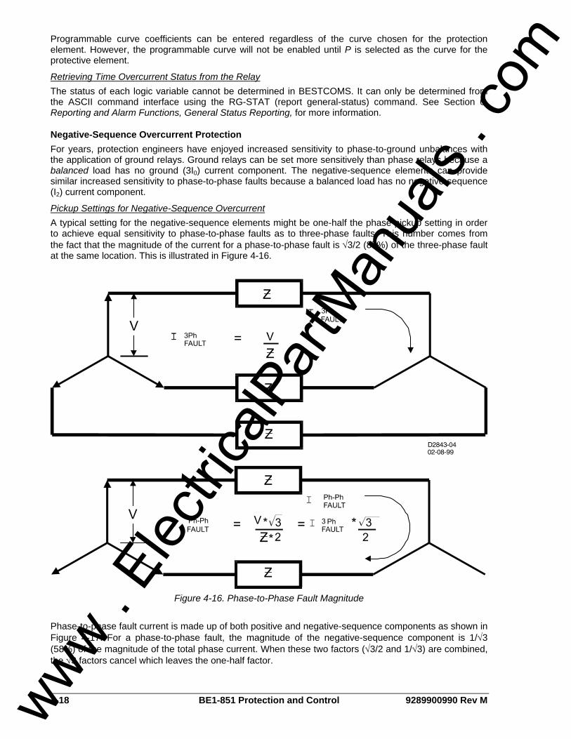
4-18 BE1-851 Protection and Control 9289900990 Rev M
Programmable curve coefficients can be entered regardless of the curve chosen for the protection element. However, the programmable curve will not be enabled until P is selected as the curve for the protective element.
Retrieving Time Overcurrent Status from the Relay The status of each logic variable cannot be determined in BESTCOMS. It can only be determined from the ASCII command interface using the RG-STAT (report general-status) command. See Section 6, Reporting and Alarm Functions, General Status Reporting, for more information.
Negative-Sequence Overcurrent Protection For years, protection engineers have enjoyed increased sensitivity to phase-to-ground unbalances with the application of ground relays. Ground relays can be set more sensitively than phase relays because a balanced load has no ground (3I0) current component. The negative-sequence elements can provide similar increased sensitivity to phase-to-phase faults because a balanced load has no negative-sequence (I2) current component.
Pickup Settings for Negative-Sequence Overcurrent A typical setting for the negative-sequence elements might be one-half the phase pickup setting in order to achieve equal sensitivity to phase-to-phase faults as to three-phase faults. This number comes from the fact that the magnitude of the current for a phase-to-phase fault is √3/2 (87%) of the three-phase fault at the same location. This is illustrated in Figure 4-16.
Figure 4-16. Phase-to-Phase Fault Magnitude
Phase-to-phase fault current is made up of both positive and negative-sequence components as shown in Figure 4-17. For a phase-to-phase fault, the magnitude of the negative-sequence component is 1/√3 (58%) of the magnitude of the total phase current. When these two factors (√3/2 and 1/√3) are combined, the √3 factors cancel which leaves the one-half factor.
www . El
ectric
alPar
tMan
uals
. com

9289900990 Rev M BE1-851 Protection and Control 4-19
Figure 4-17. Sequence Components for an A-B Fault
Coordination Settings for Negative-Sequence Overcurrent The 51Q settings should be checked for coordination with phase-only sensing devices such as downstream fuses and reclosers and/or ground relays. To plot the negative-sequence time current characteristics on the same plot for the phase devices, you need to multiply the negative-sequence element pickup value by the correct multiplier. The multiplier is the ratio of phase current to negative-sequence current for the fault type for which you are interested. To plot the negative-sequence time current characteristics on the same plot for the ground devices, you need to multiply the pickup value by the multiplier for phase-to-ground faults. See Table 4-10.
Table 4-10. Fault Type Multiplier
Fault Type Multiplier Ph-Ph m =1.732
Ph-Ph-G m > 1.732 Ph-G m =3
3-phase m = infinity
For example, a downstream phase 51 element has a pickup of 150 amperes. The upstream 51Q element has a pickup of 200 amperes. To check the coordination between these two elements for a phase-to-phase fault, the phase overcurrent element would be plotted normally with pickup at 150 amperes. The 51Q element would be shifted to the right by the appropriate factor m. Thus, the characteristic would be plotted on the coordination graph with pickup at: (200 amperes) * 1.732 = 346 amperes. Generally, for coordination with downstream phase overcurrent devices, phase-to-phase faults are the most critical to consider. All other fault types result in an equal or greater shift of the time current characteristic curve to the right on the plot.
Delta/Wye Transformer Application Often, the phase relays on the delta side of a delta/wye transformer must provide backup protection for faults on the wye side. For faults not involving ground, this is not a problem since the phase relays will see 1.0 per unit fault current for three-phase faults and 2/√3 (1.15) per unit fault current for phase-to-phase faults. However, for faults involving ground, the sensitivity is reduced because the zero-sequence components are trapped in the delta and not seen by the delta-side phase relays. The phase relays will see only 1/√3 (0.577) per unit current for phase-to-ground faults. Negative-sequence overcurrent protection is immune to the effect caused by the zero-sequence trap and 30° phase shift provided by the delta/wye transformer. For a phase-to-ground fault, the magnitude of the negative-sequence components is 1/3 the magnitude of the total fault current. On a per unit basis, this is true for the fault current on the delta side of the transformer as well. (The previous statement specifies per unit since the actual magnitudes will be adjusted by the inverse of the voltage ratio of the delta/wye transformer.) Thus, backup protection for phase-to-ground faults on the wye side of the transformer can be obtained by using negative-sequence overcurrent protection on the delta side with the pickup sensitivity set at 1/3 per unit of the magnitude of the phase-to-ground fault for which you wish to have backup protection.
www . El
ectric
alPar
tMan
uals
. com
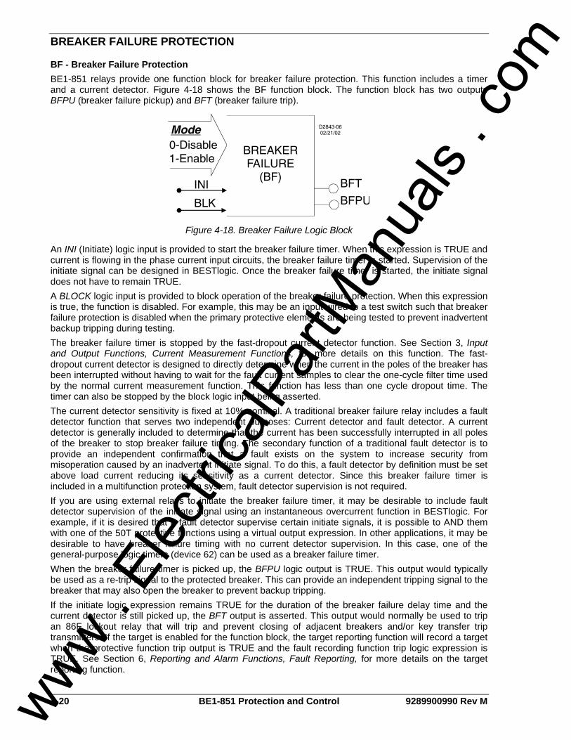
4-20 BE1-851 Protection and Control 9289900990 Rev M
BREAKER FAILURE PROTECTION
BF - Breaker Failure Protection BE1-851 relays provide one function block for breaker failure protection. This function includes a timer and a current detector. Figure 4-18 shows the BF function block. The function block has two outputs BFPU (breaker failure pickup) and BFT (breaker failure trip).
Figure 4-18. Breaker Failure Logic Block
An INI (Initiate) logic input is provided to start the breaker failure timer. When this expression is TRUE and current is flowing in the phase current input circuits, the breaker failure timer is started. Supervision of the initiate signal can be designed in BESTlogic. Once the breaker failure timer is started, the initiate signal does not have to remain TRUE. A BLOCK logic input is provided to block operation of the breaker failure protection. When this expression is true, the function is disabled. For example, this may be an input wired to a test switch such that breaker failure protection is disabled when the primary protective elements are being tested to prevent inadvertent backup tripping during testing. The breaker failure timer is stopped by the fast-dropout current detector function. See Section 3, Input and Output Functions, Current Measurement Functions, for more details on this function. The fast-dropout current detector is designed to directly determine when the current in the poles of the breaker has been interrupted without having to wait for the fault current samples to clear the one-cycle filter time used by the normal current measurement function. This function has less than one cycle dropout time. The timer can also be stopped by the block logic input being asserted. The current detector sensitivity is fixed at 10% nominal. A traditional breaker failure relay includes a fault detector function that serves two independent purposes: Current detector and fault detector. A current detector is generally included to determine that the current has been successfully interrupted in all poles of the breaker to stop breaker failure timing. The secondary function of a traditional fault detector is to provide an independent confirmation that a fault exists on the system to increase security from misoperation caused by an inadvertent initiate signal. To do this, a fault detector by definition must be set above load current reducing its sensitivity as a current detector. Since this breaker failure timer is included in a multifunction protection system, fault detector supervision is not required. If you are using external relays to initiate the breaker failure timer, it may be desirable to include fault detector supervision of the initiate signal using an instantaneous overcurrent function in BESTlogic. For example, if it is desired that a fault detector supervise certain initiate signals, it is possible to AND them with one of the 50T protective functions using a virtual output expression. In other applications, it may be desirable to have breaker failure timing with no current detector supervision. In this case, one of the general-purpose logic timers (device 62) can be used as a breaker failure timer. When the breaker failure timer is picked up, the BFPU logic output is TRUE. This output would typically be used as a re-trip signal to the protected breaker. This can provide an independent tripping signal to the breaker that may also open the breaker to prevent backup tripping. If the initiate logic expression remains TRUE for the duration of the breaker failure delay time and the current detector is still picked up, the BFT output is asserted. This output would normally be used to trip an 86F lockout relay that will trip and prevent closing of adjacent breakers and/or key transfer trip transmitters. If the target is enabled for the function block, the target reporting function will record a target when the protective function trip output is TRUE and the fault recording function trip logic expression is TRUE. See Section 6, Reporting and Alarm Functions, Fault Reporting, for more details on the target reporting function.
www . El
ectric
alPar
tMan
uals
. com
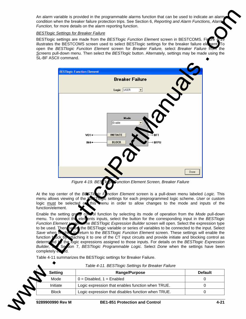
9289900990 Rev M BE1-851 Protection and Control 4-21
An alarm variable is provided in the programmable alarms function that can be used to indicate an alarm condition when the breaker failure protection trips. See Section 6, Reporting and Alarm Functions, Alarms Function, for more details on the alarm reporting function.
BESTlogic Settings for Breaker Failure BESTlogic settings are made from the BESTlogic Function Element screen in BESTCOMS. Figure 4-19 illustrates the BESTCOMS screen used to select BESTlogic settings for the breaker failure element. To open the BESTlogic Function Element screen for Breaker Failure, select Breaker Failure from the Screens pull-down menu. Then select the BESTlogic button. Alternately, settings may be made using the SL-BF ASCII command.
Figure 4-19. BESTlogic Function Element Screen, Breaker Failure
At the top center of the BESTlogic Function Element screen is a pull-down menu labeled Logic. This menu allows viewing of the BESTlogic settings for each preprogrammed logic scheme. User or custom logic must be selected on this menu in order to allow changes to the mode and inputs of the function/element. Enable the setting group control function by selecting its mode of operation from the Mode pull-down menu. To connect the elements inputs, select the button for the corresponding input in the BESTlogic Function Element screen. The BESTlogic Expression Builder screen will open. Select the expression type to be used. Then, select the BESTlogic variable or series of variables to be connected to the input. Select Save when finished to return to the BESTlogic Function Element screen. These settings will enable the function block by attaching it to one of the CT input circuits and provide initiate and blocking control as determined by the logic expressions assigned to those inputs. For details on the BESTlogic Expression Builder, see Section 7, BESTlogic Programmable Logic. Select Done when the settings have been completely edited. Table 4-11 summarizes the BESTlogic settings for Breaker Failure.
Table 4-11. BESTlogic Settings for Breaker Failure
Setting Range/Purpose Default Mode 0 = Disabled, 1 = Enabled 0 Initiate Logic expression that enables function when TRUE. 0 Block Logic expression that disables function when TRUE. 0
www . El
ectric
alPar
tMan
uals
. com
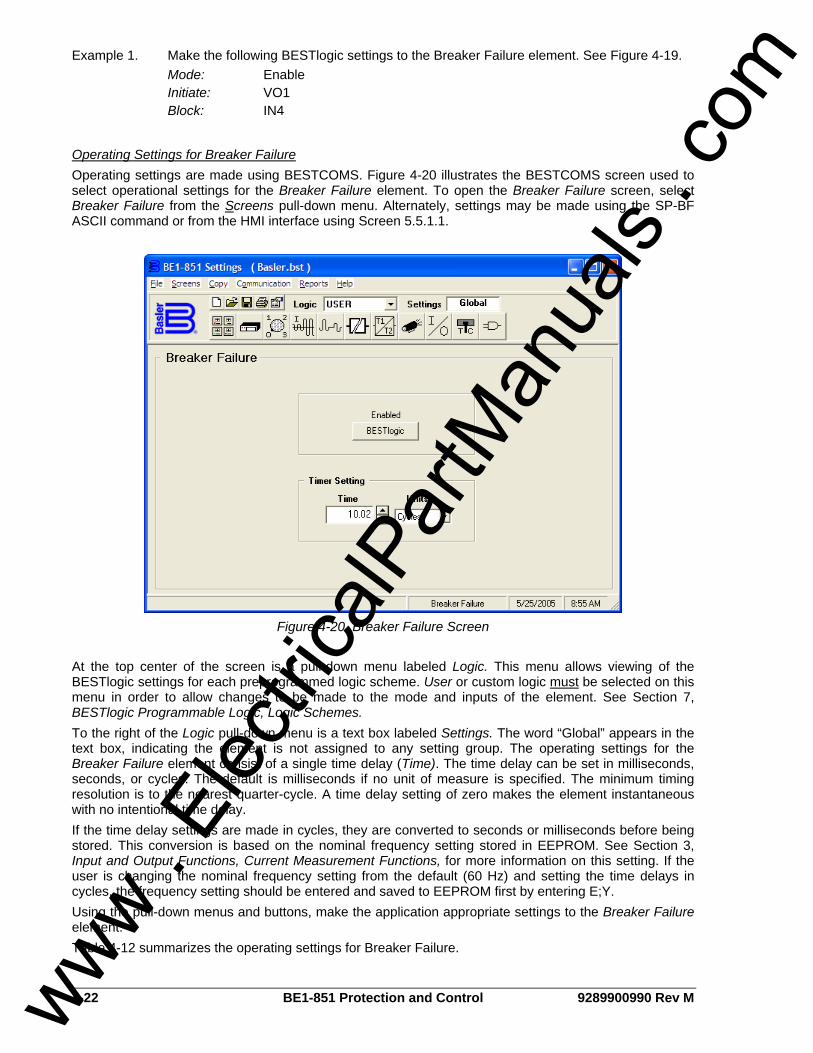
4-22 BE1-851 Protection and Control 9289900990 Rev M
Example 1. Make the following BESTlogic settings to the Breaker Failure element. See Figure 4-19. Mode: Enable Initiate: VO1 Block: IN4
Operating Settings for Breaker Failure Operating settings are made using BESTCOMS. Figure 4-20 illustrates the BESTCOMS screen used to select operational settings for the Breaker Failure element. To open the Breaker Failure screen, select Breaker Failure from the Screens pull-down menu. Alternately, settings may be made using the SP-BF ASCII command or from the HMI interface using Screen 5.5.1.1.
Figure 4-20. Breaker Failure Screen
At the top center of the screen is a pull-down menu labeled Logic. This menu allows viewing of the BESTlogic settings for each preprogrammed logic scheme. User or custom logic must be selected on this menu in order to allow changes to be made to the mode and inputs of the element. See Section 7, BESTlogic Programmable Logic, Logic Schemes. To the right of the Logic pull-down menu is a text box labeled Settings. The word “Global” appears in the text box, indicating the element is not assigned to any setting group. The operating settings for the Breaker Failure element consist of a single time delay (Time). The time delay can be set in milliseconds, seconds, or cycles. The default is milliseconds if no unit of measure is specified. The minimum timing resolution is to the nearest quarter-cycle. A time delay setting of zero makes the element instantaneous with no intentional time delay. If the time delay settings are made in cycles, they are converted to seconds or milliseconds before being stored. This conversion is based on the nominal frequency setting stored in EEPROM. See Section 3, Input and Output Functions, Current Measurement Functions, for more information on this setting. If the user is changing the nominal frequency setting from the default (60 Hz) and setting the time delays in cycles, the frequency setting should be entered and saved to EEPROM first by entering E;Y. Using the pull-down menus and buttons, make the application appropriate settings to the Breaker Failure element. Table 4-12 summarizes the operating settings for Breaker Failure.
www . El
ectric
alPar
tMan
uals
. com

9289900990 Rev M BE1-851 Protection and Control 4-23
Table 4-12. Operating Settings for Breaker Failure
Setting Range Increment Unit of Measure Default
0 = Disabled N/A N/A
50 to 999 ms 1 ms Milliseconds
0.05 to 0.999 sec. 0.001 sec. Seconds Time
0 to 59.96 (60 Hz) or 0 to 49.97 (50 Hz) ∗ Cycles
0
∗ Time delays less than 10 cycles can be entered to the nearest 0.1 cycles from the HMI. All time delays can be entered to the nearest 0.01 cycles from the ASCII command interface. Time delays entered in cycles are converted to milliseconds or seconds. Increment precision after conversion is limited to that appropriate for each of those units of measure. Example 1. Make the following operating settings to the Breaker Failure element. See Figure 4-20. Logic: User Timer Setting, Time: 10.02 cycles
Retrieving Breaker Failure Status from the Relay The status of each logic variable can be determined from the ASCII command interface using the RG-STAT (report general-status) command. Logic status cannot be determined using BESTCOMS. See Section 6, Reporting and Alarm Functions, General Status Reporting, for more information.
LOGIC TIMERS
62 - General Purpose Logic Timers BE1-851 relays provide two general-purpose logic timers that are extremely versatile. Two additional general-purpose logic timers are available when style option 1 is V or W. Each can be set for one of five modes of operation to emulate virtually any type of timer. Each function block has one output (x62, where x = none, 1, 2, or 3) that is asserted when the timing criteria has been met according to the BESTlogic mode setting. Figure 4-21 shows the 62 function block as an example. Each mode of operation is described in detail in the following paragraphs.
Figure 4-21. General Purpose Logic Timers Logic Block
An INITIATE logic input is provided to start the timing sequence. A BLOCK logic input is provided to block operation of the timer. When this expression is TRUE, the function is disabled. Each timer has a T1 time setting and a T2 time setting. The functioning of these settings is dependent upon the type of timer as specified by the mode setting in BESTlogic.
If the target is enabled for the function block, the target reporting function will record a target when the timer output is TRUE and the fault recording function trip logic expression is TRUE. See Section 6, Reporting and Alarm Functions, Fault Reporting, for more details on the target reporting function.
www . El
ectric
alPar
tMan
uals
. com
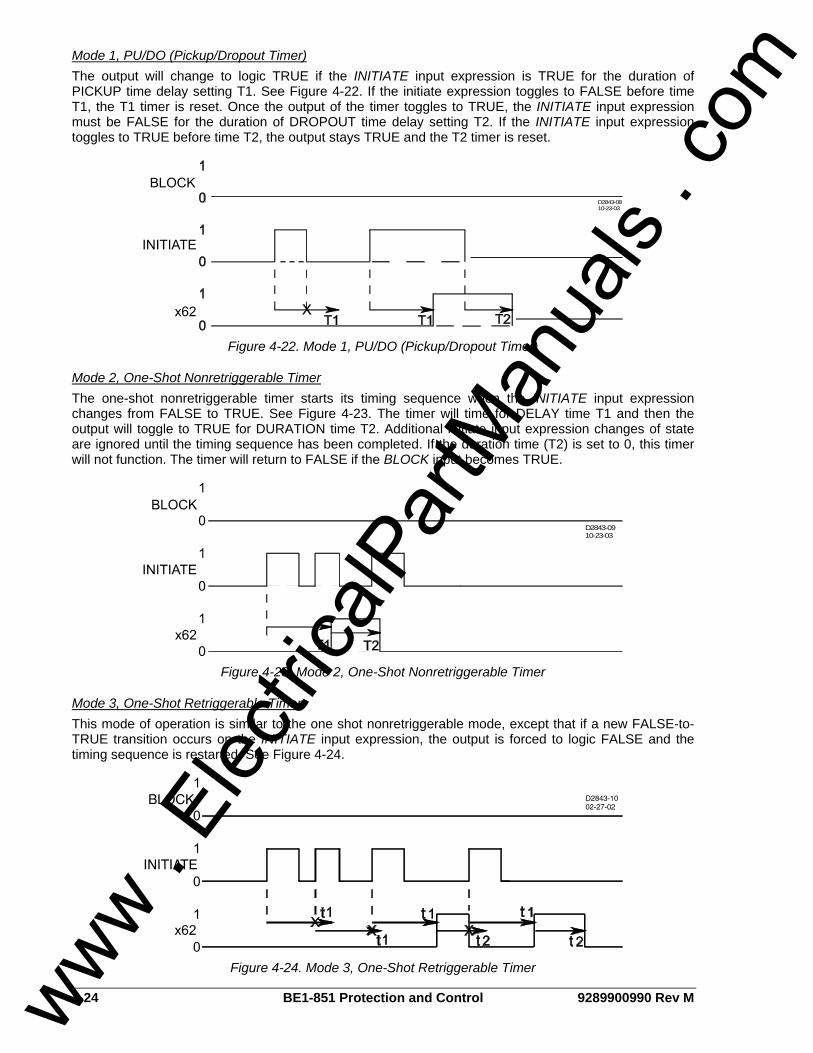
4-24 BE1-851 Protection and Control 9289900990 Rev M
Mode 1, PU/DO (Pickup/Dropout Timer) The output will change to logic TRUE if the INITIATE input expression is TRUE for the duration of PICKUP time delay setting T1. See Figure 4-22. If the initiate expression toggles to FALSE before time T1, the T1 timer is reset. Once the output of the timer toggles to TRUE, the INITIATE input expression must be FALSE for the duration of DROPOUT time delay setting T2. If the INITIATE input expression toggles to TRUE before time T2, the output stays TRUE and the T2 timer is reset.
D2843-0810-23-03
Figure 4-22. Mode 1, PU/DO (Pickup/Dropout Timer)
Mode 2, One-Shot Nonretriggerable Timer The one-shot nonretriggerable timer starts its timing sequence when the INITIATE input expression changes from FALSE to TRUE. See Figure 4-23. The timer will time for DELAY time T1 and then the output will toggle to TRUE for DURATION time T2. Additional initiate input expression changes of state are ignored until the timing sequence has been completed. If the duration time (T2) is set to 0, this timer will not function. The timer will return to FALSE if the BLOCK input becomes TRUE.
D2843-0910-23-03
Figure 4-23. Mode 2, One-Shot Nonretriggerable Timer
Mode 3, One-Shot Retriggerable Timer This mode of operation is similar to the one shot nonretriggerable mode, except that if a new FALSE-to-TRUE transition occurs on the INITIATE input expression, the output is forced to logic FALSE and the timing sequence is restarted. See Figure 4-24.
Figure 4-24. Mode 3, One-Shot Retriggerable Timer
www . El
ectric
alPar
tMan
uals
. com
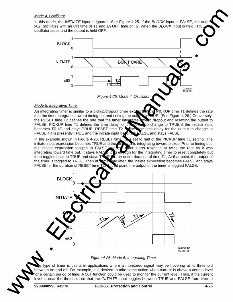
9289900990 Rev M BE1-851 Protection and Control 4-25
Mode 4, Oscillator In this mode, the INITIATE input is ignored. See Figure 4-25. If the BLOCK input is FALSE, the output, x62, oscillates with an ON time of T1 and an OFF time of T2. When the BLOCK input is held TRUE, the oscillator stops and the output is held OFF.
Figure 4-25. Mode 4, Oscillator
Mode 5, Integrating Timer An integrating timer is similar to a pickup/dropout timer except that the PICKUP time T1 defines the rate that the timer integrates toward timing out and setting the output to TRUE. (See Figure 4-26.) Conversely, the RESET time T2 defines the rate that the timer integrates toward dropout and resetting the output to FALSE. PICKUP time T1 defines the time delay for the output to change to TRUE if the initiate input becomes TRUE and stays TRUE. RESET time T2 defines the time delay for the output to change to FALSE if it is presently TRUE and the initiate input becomes FALSE and stays FALSE. In the example shown in Figure 4-26, RESET time T2 is set to half of the PICKUP time T1 setting. The initiate input expression becomes TRUE and the timer starts integrating toward pickup. Prior to timing out, the initiate expression toggles to FALSE and the timer starts resetting at twice the rate as it was integrating toward time out. It stays FALSE long enough for the integrating timer to reset completely but then toggles back to TRUE and stays TRUE for the entire duration of time T1. At that point, the output of the timer is toggled to TRUE. Then at some time later, the initiate expression becomes FALSE and stays FALSE for the duration of RESET time T2. At that point, the output of the timer is toggled FALSE.
D2843-1210-23-03
Figure 4-26. Mode 5, Integrating Timer
This type of timer is useful in applications where a monitored signal may be hovering at its threshold between on and off. For example, it is desired to take some action when current is above a certain level for a certain period of time. A 50T function could be used to monitor the current level. Thus, if the current level is near the threshold so that the INITIATE input toggles between TRUE and FALSE from time to
www . El
ectric
alPar
tMan
uals
. com
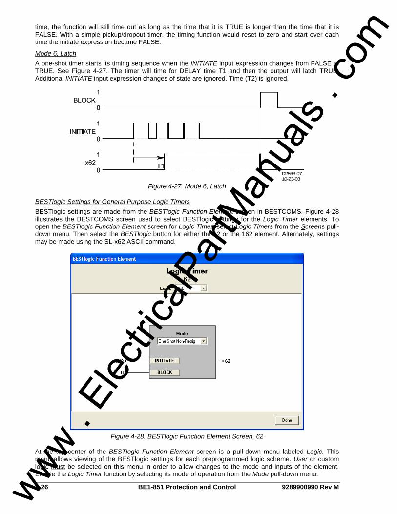
4-26 BE1-851 Protection and Control 9289900990 Rev M
time, the function will still time out as long as the time that it is TRUE is longer than the time that it is FALSE. With a simple pickup/dropout timer, the timing function would reset to zero and start over each time the initiate expression became FALSE.
Mode 6, Latch A one-shot timer starts its timing sequence when the INITIATE input expression changes from FALSE to TRUE. See Figure 4-27. The timer will time for DELAY time T1 and then the output will latch TRUE. Additional INITIATE input expression changes of state are ignored. Time (T2) is ignored.
D2863-0710-23-03
Figure 4-27. Mode 6, Latch
BESTlogic Settings for General Purpose Logic Timers BESTlogic settings are made from the BESTlogic Function Element screen in BESTCOMS. Figure 4-28 illustrates the BESTCOMS screen used to select BESTlogic settings for the Logic Timer elements. To open the BESTlogic Function Element screen for Logic Timer, select Logic Timers from the Screens pull-down menu. Then select the BESTlogic button for either the 62 or the 162 element. Alternately, settings may be made using the SL-x62 ASCII command.
Figure 4-28. BESTlogic Function Element Screen, 62
At the top center of the BESTlogic Function Element screen is a pull-down menu labeled Logic. This menu allows viewing of the BESTlogic settings for each preprogrammed logic scheme. User or custom logic must be selected on this menu in order to allow changes to the mode and inputs of the element. Enable the Logic Timer function by selecting its mode of operation from the Mode pull-down menu.
www . El
ectric
alPar
tMan
uals
. com
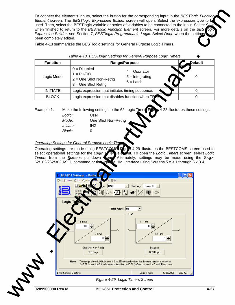
9289900990 Rev M BE1-851 Protection and Control 4-27
To connect the element’s inputs, select the button for the corresponding input in the BESTlogic Function Element screen. The BESTlogic Expression Builder screen will open. Select the expression type to be used. Then, select the BESTlogic variable or series of variables to be connected to the input. Select Save when finished to return to the BESTlogic Function Element screen. For more details on the BESTlogic Expression Builder, see Section 7, BESTlogic Programmable Logic. Select Done when the settings have been completely edited. Table 4-13 summarizes the BESTlogic settings for General Purpose Logic Timers.
Table 4-13. BESTlogic Settings for General Purpose Logic Timers
Function Range/Purpose Default
Logic Mode
0 = Disabled 1 = PU/DO 2 = One Shot Non-Retrig 3 = One Shot Retrig
4 = Oscillator 5 = Integrating 6 = Latch
0
INITIATE Logic expression that initiates timing sequence. 0 BLOCK Logic expression that disables function when TRUE. 0
Example 1. Make the following settings to the 62 Logic Timer. Figure 4-28 illustrates these settings. Logic: User Mode: One Shot Non-Retrig Initiate: IN2 Block: 0
Operating Settings for General Purpose Logic Timers Operating settings are made using BESTCOMS. Figure 4-29 illustrates the BESTCOMS screen used to select operational settings for the Logic Timers element. To open the Logic Timers screen, select Logic Timers from the Screens pull-down menu. Alternately, settings may be made using the S<g>-62/162/262/362 ASCII command or through the HMI interface using Screens 5.x.3.1 through 5.x.3.4.
Figure 4-29. Logic Timers Screen
www . El
ectric
alPar
tMan
uals
. com

4-28 BE1-851 Protection and Control 9289900990 Rev M
At the top center of the screen is a pull-down menu labeled Logic. This menu allows viewing of the BESTlogic settings for each preprogrammed logic scheme. User or custom logic must be selected on this menu in order to allow changes to be made to the mode and inputs of the element. To the right of the Logic pull-down menu is a pull-down menu labeled Settings. The Settings menu is used to select the setting group that the element’s settings apply to. See Section 7, BESTlogic Programmable Logic, Logic Schemes. Using the pull-down menus and buttons, make the application appropriate settings to the Logic Timers element. Table 4-14 summarizes the operating settings for General Purpose Logic Timers.
Table 4-14. Operating Settings for General Purpose Logic Timers
Setting Range Increment Unit of Measure Default 0 to 999 ms 1 Milliseconds
0.1 for 0.1 to 9.9 sec. 0.1 to 9999 sec.
1.0 for 10 to 9999 sec. Seconds T1 Time,
T2 Time 0 to 599,940 (60 Hz) 0 to 499,950 (50Hz) ∗ Cycles
0
∗ Time delays less than 10 cycles can be entered to the nearest 0.1 cycles through the HMI. All time delays can be entered to the nearest 0.01 cycles from the ASCII command interface. Time delays entered in cycles are converted to milliseconds or seconds. Increment precision after conversion is limited to that appropriate for each of those units of measure. Example 1. Make the following operating settings to the 62 element. See Figure 4-29. Logic: User Setting: Group 0 Time Units: ms T1 Time: 100 T2 Time: 0
Retrieving General Purpose Logic Timers Status from the Relay The status of each logic variable can be determined from the ASCII command interface by using the RG-STAT (report general-status) command. Status cannot be determined using BESTCOMS. See Section 6, Reporting and Alarm Functions, General Status Reporting, for more information.
RECLOSING The BE1-851 reclosing function provides up to four reclosing attempts that can be initiated by a protective trip or by one of the contact sensing inputs. The reclosers allow supervisory control and coordination of tripping and reclosing with other system devices. Any of the four recloser shots can be used to select a different setting group when the appropriate shot is reached in a reclosing sequence. This change in setting groups allows changing protection coordination during the reclosing sequence. For example, you could have a fast 51 curve on the first two trips in the reclosing sequence and then switch to a new group on the second reclose that uses a slow 51 curve. Detailed information about relay setting groups can be found earlier in this section under the heading of Setting Groups. Recloser function block inputs and outputs are shown in Figure 4-30 and are described in the following paragraphs. An overall logic diagram for the recloser function is shown in Figure 4-38.
Figure 4-30. Reclosing Logic Block
www . El
ectric
alPar
tMan
uals
. com
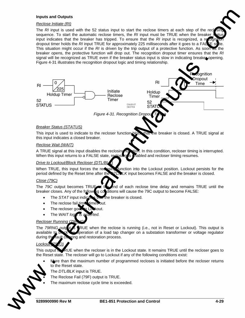
9289900990 Rev M BE1-851 Protection and Control 4-29
Inputs and Outputs
Reclose Initiate (RI) The RI input is used with the 52 status input to start the reclose timers at each step of the reclosing sequence. To start the automatic reclose timers, the RI input must be TRUE when the breaker status input indicates that the breaker has tripped. To ensure that the RI input is recognized, a recognition dropout timer holds the RI input TRUE for approximately 225 milliseconds after it goes to a FALSE state. This situation might occur if the RI is driven by the trip output of a protective function. As soon as the breaker opens, the protective function will drop out. The recognition dropout timer ensures that the RI signal will be recognized as TRUE even if the breaker status input is slow in indicating breaker opening. Figure 4-31 illustrates the recognition dropout logic and timing relationship.
Figure 4-31. Recognition Dropout Timing
Breaker Status (STATUS) This input is used to indicate to the recloser function block that the breaker is closed. A TRUE signal at this input indicates a closed breaker.
Reclose Wait (WAIT) A TRUE signal at this input disables the reclosing function. In this condition, recloser timing is interrupted. When this input returns to a FALSE state, reclosing is enabled and recloser timing resumes.
Drive to Lockout/Block Recloser (DTL/BLK) When TRUE, this input forces the reclosing function into the Lockout position. Lockout persists for the period defined by the Reset time after the DTL/BLK input becomes FALSE and the breaker is closed.
Close (79C) The 79C output becomes TRUE at the end of each reclose time delay and remains TRUE until the breaker closes. Any of the following conditions will cause the 79C output to become FALSE:
• The STAT input indicates that the breaker is closed. • The reclose fail timer times out. • The recloser goes to Lockout. • The WAIT logic is asserted.
Recloser Running (79RNG) The 79RNG output is TRUE when the reclose is running (i.e., not in Reset or Lockout). This output is available to block the operation of a load tap changer on a substation transformer or voltage regulator during the fault clearing and restoration process.
Lockout (79LO) This output is TRUE when the recloser is in the Lockout state. It remains TRUE until the recloser goes to the Reset state. The recloser will go to Lockout if any of the following conditions exist:
• More than the maximum number of programmed recloses is initiated before the recloser returns to the Reset state.
• The DTL/BLK input is TRUE. • The Reclose Fail (79F) output is TRUE. • The maximum reclose cycle time is exceeded.
www . El
ectric
alPar
tMan
uals
. com
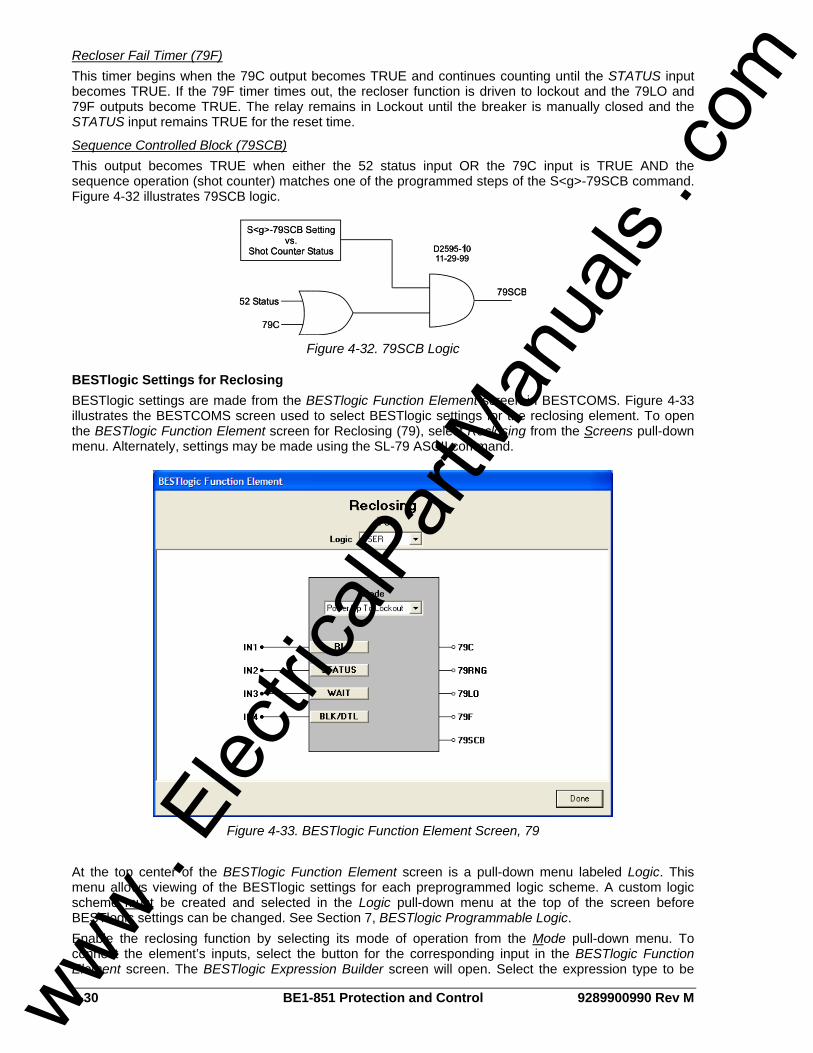
4-30 BE1-851 Protection and Control 9289900990 Rev M
Recloser Fail Timer (79F) This timer begins when the 79C output becomes TRUE and continues counting until the STATUS input becomes TRUE. If the 79F timer times out, the recloser function is driven to lockout and the 79LO and 79F outputs become TRUE. The relay remains in Lockout until the breaker is manually closed and the STATUS input remains TRUE for the reset time.
Sequence Controlled Block (79SCB) This output becomes TRUE when either the 52 status input OR the 79C input is TRUE AND the sequence operation (shot counter) matches one of the programmed steps of the S<g>-79SCB command. Figure 4-32 illustrates 79SCB logic.
Figure 4-32. 79SCB Logic
BESTlogic Settings for Reclosing BESTlogic settings are made from the BESTlogic Function Element screen in BESTCOMS. Figure 4-33 illustrates the BESTCOMS screen used to select BESTlogic settings for the reclosing element. To open the BESTlogic Function Element screen for Reclosing (79), select Reclosing from the Screens pull-down menu. Alternately, settings may be made using the SL-79 ASCII command.
Figure 4-33. BESTlogic Function Element Screen, 79
At the top center of the BESTlogic Function Element screen is a pull-down menu labeled Logic. This menu allows viewing of the BESTlogic settings for each preprogrammed logic scheme. A custom logic scheme must be created and selected in the Logic pull-down menu at the top of the screen before BESTlogic settings can be changed. See Section 7, BESTlogic Programmable Logic. Enable the reclosing function by selecting its mode of operation from the Mode pull-down menu. To connect the element’s inputs, select the button for the corresponding input in the BESTlogic Function Element screen. The BESTlogic Expression Builder screen will open. Select the expression type to be
www . El
ectric
alPar
tMan
uals
. com
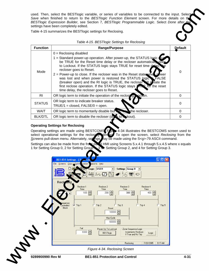
9289900990 Rev M BE1-851 Protection and Control 4-31
used. Then, select the BESTlogic variable, or series of variables to be connected to the input. Select Save when finished to return to the BESTlogic Function Element screen. For more details on the BESTlogic Expression Builder, see Section 7, BESTlogic Programmable Logic. Select Done after the settings have been completely edited. Table 4-15 summarizes the BESTlogic settings for Reclosing.
Table 4-15. BESTlogic Settings for Reclosing
Function Range/Purpose Default
Mode
0 = Reclosing disabled 1 = Standard power-up operation. After power-up, the STATUS logic must
be TRUE for the Reset time delay or the recloser automatically goes to Lockout. If the STATUS logic stays TRUE for reset time delay, the recloser goes to Reset.
2 = Power-up to close. If the recloser was in the Reset state when power was lost and when power is restored the STATUS logic is FALSE (breaker open) and the RI logic is TRUE, the recloser will initiate the first reclose operation. If the STATUS logic stays TRUE for the reset time delay, the recloser goes to Reset.
0
RI OR logic term to initiate the operation of the reclosing function. 0
STATUS OR logic term to indicate breaker status. TRUE/1 = closed, FALSE/0 = open. 0
WAIT OR logic term to momentarily disable but not reset the recloser. 0 BLK/DTL OR logic term to disable the recloser (drive to lockout). 0
Operating Settings for Reclosing Operating settings are made using BESTCOMS. Figure 4-34 illustrates the BESTCOMS screen used to select operational settings for the reclosing element. To open the screen, select Reclosing from the Screens pull-down menu. Alternately, settings may be made using the S<g>-79 ASCII command. Settings can also be made from the front panel HMI using Screens 5.x.4.1 through 5.x.4.5 where x equals 1 for Setting Group 0, 2 for Setting Group 1, 3 for Setting Group 2, and 4 for Setting Group 3.
Figure 4-34. Reclosing Screen
www . El
ectric
alPar
tMan
uals
. com

4-32 BE1-851 Protection and Control 9289900990 Rev M
At the top of the screen is a pull-down menu labeled Logic. This menu allows viewing of the BESTlogic settings for each preprogrammed logic scheme. A custom logic scheme must be created and selected in the Logic pull-down menu at the top of the screen before BESTlogic setting can be changed. See Section 7, BESTlogic Programmable Logic. To the right of the Logic pull-down menu is a pull-down menu labeled Settings. The Settings menu is used to select the setting group that the element’s settings apply to. Selecting the time units selects the time measurement that applies to all of the reclosing timers, Reset timer, Max Cycle timer, and Reset Fail timer. Using the pull-down menus and buttons, make the application appropriate settings to the reclosing function. Table 4-16 summarizes the operating settings for Reclosing.
Table 4-16. Operating Settings for Reclosing
Setting Range Increment Default 791 = 0 792 = 0 793 = 0 794 = 0
79R = 10s 79F = 1s
Time Delays
0.1 to 600 seconds
0.001 second (0 to 0.999 seconds) 0.1 second (1.0 to 9.9 seconds) 1 second (10 to 600 seconds) 0.1 cycles (6 to 36000 cycles)
79M = 60s
Step List
1. 79SCB TRUE during Reset and while timing to Reset after Lockout.
2. 79SCB TRUE when 79C is TRUE for first reclose and while timing to Reset after first reclose.
3. 79SCB TRUE when 79C is TRUE for second reclose and while timing to Reset after second reclose.
4. 79SCB TRUE when 79C is TRUE for third reclose and while timing to Reset after third reclose.
5. 79SCB TRUE when 79C is TRUE for fourth reclose and while timing to Reset after fourth reclose.
0
Reset Timer (79RST) The 79RST is TRUE when the recloser is in the reset position. This setting can be changed on the Reclosing screen in BESTCOMS. See Figure 4-34.
Maximum Cycle Timer (MAX Cycle) Max Cycle is the reclose maximum operation time. If a reclose operation is not completed before the maximum operate time expires, the recloser goes to Lockout. This timer limits the total fault clearing and restoration sequence to a definable period. The timer starts when the first trip command is issued from a protective element of the relay. The Max Cycle timer stops when the recloser is reset. If the total reclosing time between Reset states exceeds the maximum reclose cycle timer setting, the recloser will go Lockout. If the WAIT input goes high during the Max Cycle timing sequence, Max Cycle timing will “pause” until the WAIT input goes low. If not desired, the Max Cycle timer can be disabled by setting it at zero. This setting can be changed on the Reclosing screen in BESTCOMS. See Figure 4-34.
Sequence Controlled Block (SCB) The 79SCB output is TRUE when the breaker is closed, the 79 close output (79C) is TRUE, and the reclose sequence step is enabled with a non-zero value in the S#-79SCB command. A 0 (zero) disables the 79SCB output. This setting can be changed on the Reclosing screen in BESTCOMS. See Figure 4-34. Figure 4-35 shows a logic timing diagram showing all possible sequence control blocks enabled (TRUE). In Figure 4-36, 79RTD is the reclose reset time delay and 79#TD is the reclose time delay where # is the reclose shot number.
www . El
ectric
alPar
tMan
uals
. com
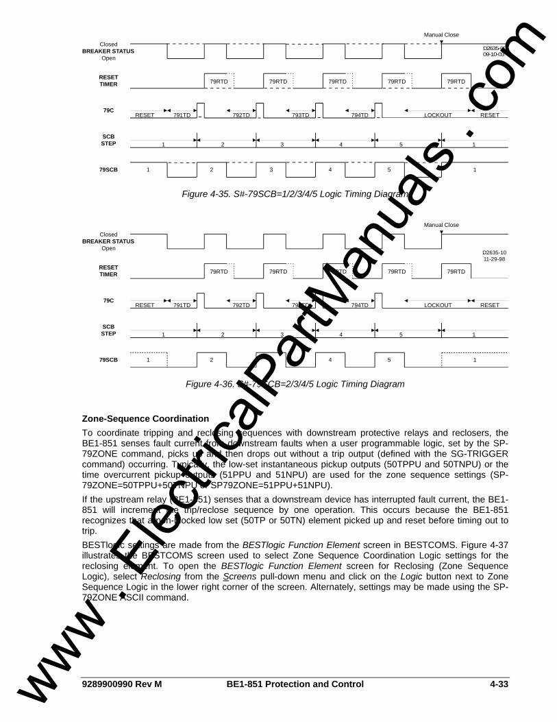
9289900990 Rev M BE1-851 Protection and Control 4-33
79RTD 79RTD 79RTD 79RTD 79RTD
RESET 791TD 792TD 793TD 794TD LOCKOUT RESET
Manual Close
1 2 3 4 5 1
1 2 3 4 5 1
ClosedBREAKER STATUS
Open
RESETTIMER
79C
SCBSTEP
79SCB
D2635-0909-10-03
Figure 4-35. S#-79SCB=1/2/3/4/5 Logic Timing Diagram
79RTD 79RTD 79RTD 79RTD 79RTD
RESET 791TD 792TD 793TD 794TD LOCKOUT RESET
Manual Close
1 2 3 4 5 1
1 2 3 4 5 1
ClosedBREAKER STATUS
Open
RESETTIMER
79C
SCBSTEP
79SCB
D2635-1011-29-98
Figure 4-36. S#-79SCB=2/3/4/5 Logic Timing Diagram
Zone-Sequence Coordination To coordinate tripping and reclosing sequences with downstream protective relays and reclosers, the BE1-851 senses fault current from downstream faults when a user programmable logic, set by the SP-79ZONE command, picks up and then drops out without a trip output (defined with the SG-TRIGGER command) occurring. Typically, the low-set instantaneous pickup outputs (50TPPU and 50TNPU) or the time overcurrent pickup outputs (51PPU and 51NPU) are used for the zone sequence settings (SP-79ZONE=50TPPU+50TNPU or SP79ZONE=51PPU+51NPU). If the upstream relay (BE1-851) senses that a downstream device has interrupted fault current, the BE1-851 will increment the trip/reclose sequence by one operation. This occurs because the BE1-851 recognizes that a non-blocked low set (50TP or 50TN) element picked up and reset before timing out to trip. BESTlogic settings are made from the BESTlogic Function Element screen in BESTCOMS. Figure 4-37 illustrates the BESTCOMS screen used to select Zone Sequence Coordination Logic settings for the reclosing element. To open the BESTlogic Function Element screen for Reclosing (Zone Sequence Logic), select Reclosing from the Screens pull-down menu and click on the Logic button next to Zone Sequence Logic in the lower right corner of the screen. Alternately, settings may be made using the SP-79ZONE ASCII command.
www . El
ectric
alPar
tMan
uals
. com
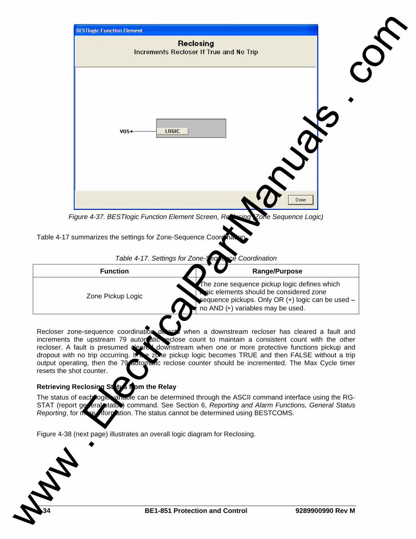
4-34 BE1-851 Protection and Control 9289900990 Rev M
Figure 4-37. BESTlogic Function Element Screen, Reclosing (Zone Sequence Logic)
Table 4-17 summarizes the settings for Zone-Sequence Coordination.
Table 4-17. Settings for Zone-Sequence Coordination
Function Range/Purpose
Zone Pickup Logic
The zone sequence pickup logic defines which logic elements should be considered zone sequence pickups. Only OR (+) logic can be used – no AND (∗) variables may be used.
Recloser zone-sequence coordination detects when a downstream recloser has cleared a fault and increments the upstream 79 automatic reclose count to maintain a consistent count with the other recloser. A fault is presumed cleared downstream when one or more protective functions pickup and dropout with no trip occurring. If the zone pickup logic becomes TRUE and then FALSE without a trip output operating, then the 79 automatic reclose counter should be incremented. The Max Cycle timer resets the shot counter.
Retrieving Reclosing Status from the Relay The status of each logic variable can be determined through the ASCII command interface using the RG-STAT (report general-status) command. See Section 6, Reporting and Alarm Functions, General Status Reporting, for more information. The status cannot be determined using BESTCOMS. Figure 4-38 (next page) illustrates an overall logic diagram for Reclosing.
www . El
ectric
alPar
tMan
uals
. com
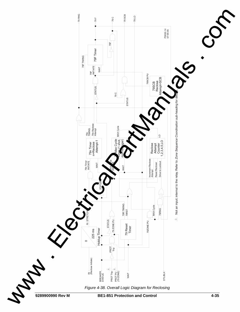
9289900990 Rev M BE1-851 Protection and Control 4-35
Figure 4-38. Overall Logic Diagram for Reclosing
www . El
ectric
alPar
tMan
uals
. com

4-36 BE1-851 Protection and Control 9289900990 Rev M
VIRTUAL SWITCHES
43 - Virtual Selector Switches BE1-851 relays have four virtual selector switches that can provide manual control, locally and remotely, without using physical switches and/or interposing relays. Only two virtual selector switches are provided when style option 1 is V or W. Each virtual switch can be set for one of three modes of operation to emulate virtually any type of binary (two position) switch. An example would be an application that requires a recloser or 51N ground cutoff. The traditional approach might be to install a switch on the panel and wire the output to a contact sensing input on the relay. Instead, a virtual switch can be used to reduce costs with the added benefit of being able to operate the switch both locally through the HMI and remotely from a substation computer or through a modem connection to a remote operator’s console. The state of the switches can be controlled from the HMI or ASCII command interface. The BESTlogic mode setting can set control actions. When set for the On/Off/Pulse mode, each switch can be controlled to open (logic 0), close (logic 1), or pulse such that the output toggles from its current state to the opposite state and then returns. Additional modes allow the switch operation to be restricted. In the On/Off mode, the switch emulates a two-position selector switch, and only open and close commands are accepted. In the Off/Momentary On mode, a momentary close, spring return switch is emulated and only the pulse command is accepted. Because switch status information is saved in nonvolatile memory, the relay powers up with the switches in the same state as when the relay was powered down. Each virtual selector switch function block (see Figure 4-39) has one output: 43, 143, 243, or 343. The output is TRUE when the switch is in the closed state; the output is FALSE when the switch is in the open state. Since both the output and the inverse of the output of these switches can be used as many times as desired in your programmable logic, they can emulate a switch with as many normally open and normally closed decks as desired.
43
Mode0-Disable1-On/Off/Pulse2-On/Off3-Off/Momentary On
43 AUXSWITCH
D2861-0503-13-00
Figure 4-39. Virtual Selector Switches Logic Block
User specified labels could be assigned to each virtual switch and to both states of each switch. In the previous differential cutoff switch example, you might enable one of the switches in BESTlogic as On/Off and connect the output of that switch to the Block input of the 51P protection element block. This would disable the differential when the switch is closed (logic 1) and enable it when the switch is open (logic 0). For the application, you might set the switch label to be 51_CUTOFF (10 character maximum). The closed position on the switch might be labeled DISABLD (7 character maximum) and the open position might be labeled NORMAL. Section 7, BESTlogic Programmable Logic, has more details about setting user programmable names for programmable logic variables.
BESTlogic Settings for Virtual Selector Switches BESTlogic settings are made from the BESTlogic Function Element screen in BESTCOMS. Figure 4-40 illustrates the BESTCOMS screen used to select BESTlogic setting for the Virtual Switch element. To open the BESTlogic Function Element screen for Virtual Switch, select Virtual Switches from the Screens pull-down menu. Then select the BESTlogic button for the 43, 143, 243, or 343 element. Alternately, settings may be made using SL-<x>43 ASCII command.
www . El
ectric
alPar
tMan
uals
. com
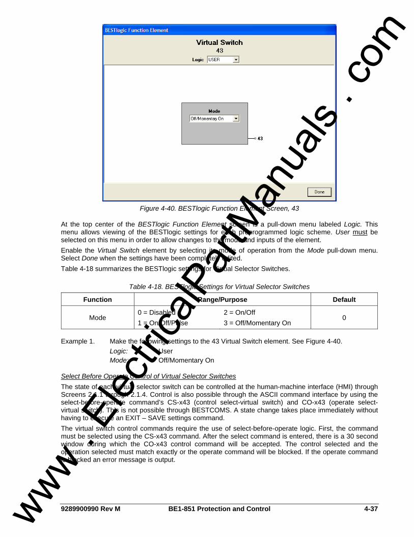
9289900990 Rev M BE1-851 Protection and Control 4-37
Figure 4-40. BESTlogic Function Element Screen, 43
At the top center of the BESTlogic Function Element screen is a pull-down menu labeled Logic. This menu allows viewing of the BESTlogic settings for each preprogrammed logic scheme. User must be selected on this menu in order to allow changes to the mode and inputs of the element. Enable the Virtual Switch element by selecting its mode of operation from the Mode pull-down menu. Select Done when the settings have been completely edited. Table 4-18 summarizes the BESTlogic settings for Virtual Selector Switches.
Table 4-18. BESTlogic Settings for Virtual Selector Switches
Function Range/Purpose Default
Mode 0 = Disabled 1 = On/Off/Pulse
2 = On/Off 3 = Off/Momentary On
0
Example 1. Make the following settings to the 43 Virtual Switch element. See Figure 4-40. Logic: User Mode: Off/Momentary On
Select Before Operate Control of Virtual Selector Switches The state of each virtual selector switch can be controlled at the human-machine interface (HMI) through Screens 2.1.1 through 2.1.4. Control is also possible through the ASCII command interface by using the select-before-operate command’s CS-x43 (control select-virtual switch) and CO-x43 (operate select-virtual switch). This is not possible through BESTCOMS. A state change takes place immediately without having to execute an EXIT – SAVE settings command. The virtual switch control commands require the use of select-before-operate logic. First, the command must be selected using the CS-x43 command. After the select command is entered, there is a 30 second window during which the CO-x43 control command will be accepted. The control selected and the operation selected must match exactly or the operate command will be blocked. If the operate command is blocked an error message is output.
www . El
ectric
alPar
tMan
uals
. com

4-38 BE1-851 Protection and Control 9289900990 Rev M
CS/CO-x43 Command Examples:
Example 1. Read the current status of virtual switch 43. >CO-43 0
Example 2. Momentarily toggle the state of switch 43 to closed. >CS-43=P 43=P SELECTED >CO-43=P 43=P EXECUTED
Example 3. An example of an operate command not matching the select command. >CS-243=P CS-243 SELECTED >CO-243=1 ERROR:NO SELECT
Retrieving Virtual Selector Switches Status from the Relay The state of each virtual selector switch can be determined from HMI Screen 1.5.4. This information is also available through the ASCII command interface by using the RG-STAT or RG-x43STAT commands. This is not available through BESTCOMS. See Section 6, Reporting and Alarm Functions, General Status Reporting, for more information. HMI Screens 2.1.1 through 2.1.4 provide switch control and can also display the current status of their respective switches. ASCII command CO-x43 returns the state of each virtual selector switch in a read-only mode. See the previous example 1.
101 - Virtual Breaker Control Switch The virtual breaker control switch (see Figure 4-41) provides manual control of a circuit breaker or switch without using physical switches and/or interposing relays. Both local and remote control is possible. A virtual switch can be used instead of a physical switch to reduce costs with the added benefit that the virtual switch can be operated both locally from the HMI and remotely from a substation computer or modem connection to an operator’s console.
D2861-0608-05-99
Figure 4-41. 101 Function Block
The breaker control switch emulates a typical breaker control switch with a momentary close, spring return, trip contact (Output 101T), a momentary close, spring return, close contact (Output 101C), and a slip contact (Output 101SC). The slip contact output retains the status of the last control action. That is, it is FALSE (open) in the after-trip state and TRUE (closed) in the after-close state. Figure 4-42 shows the state of the 101SC logic output with respect to the state of the 101T and 101C Outputs.
www . El
ectric
alPar
tMan
uals
. com

9289900990 Rev M BE1-851 Protection and Control 4-39
Figure 4-42. 101 Control Switch State Diagram When the virtual control switch is controlled to trip, the 101T output pulses TRUE (closed) for approximately 200 milliseconds and the 101SC output goes FALSE (open). When the virtual control switch is controlled to close, the 101SC output pulses TRUE (closed). The status of the slip contact output is saved to nonvolatile memory so that the relay will power up with the contact in the same state as when the relay was powered down.
BESTlogic Settings for Virtual Breaker Control Switch BESTlogic settings are made from the BESTlogic Function Element screen in BESTCOMS. Figure 4-43 illustrates the BESTCOMS screen used to select BESTlogic settings for the Virtual Breaker Control 101 element. To open the BESTlogic Function Element screen for Virtual Breaker Control 101, select Virtual Switches from the Screens pull-down menu. Then select the BESTlogic button in for the 101 element. Alternately, setting may be made using the SL-101 ASCII command.
Figure 4-43. BESTlogic Function Element Screen, 101
At the top center of the BESTlogic Function Element screen is a pull-down menu labeled Logic. This menu allows viewing of the BESTlogic settings for each preprogrammed logic scheme. User must be selected on this menu in order to allow changes to the mode and inputs of the element. Enable the Virtual Breaker Control 101 element by selecting its mode of operation from the Mode pull-down menu. Select Done when the settings have been completely edited. Table 4-19 summarizes the BESTlogic settings for Virtual Breaker Control Switch.
www . El
ectric
alPar
tMan
uals
. com

4-40 BE1-851 Protection and Control 9289900990 Rev M
Table 4-19. BESTlogic Settings for Virtual Breaker Control Switch
Function Range/Purpose Default
Mode 0 = Disable, 1 = Enable 0
Example 1. Make the following BESTlogic settings to the Virtual Breaker Control 101 element. Figure
4-43 illustrates these settings. Logic: User Mode: Enable
Select Before Operate Control of Virtual Breaker Control Switch The state of each virtual selector switch can be controlled at the HMI through Screen 2.2.1. Control is also possible through the ASCII command interface by using the select-before-operate commands CS-101 (control select-virtual control switch) and CO-101 (control operate-virtual control switch). This cannot be done using BESTCOMS. A state change takes place immediately without having to execute an EXIT – SAVE settings command. The virtual switch control commands require the use of select-before-operate logic. First, the command must be selected using the CS-101 command. After the select command is entered, there is a 30 second window during which the CO-101 control command will be accepted. The control selected and the operation selected must match exactly or the operate command will be blocked. If the operate command is blocked, an error message is output. CS/CO Command Examples:
Example 1. Read the current status of the virtual control switch. >CO-101 C
The returned setting indicated that the switch is in the after-close state. Example 2. Trip the breaker by closing the trip output of the virtual control switch. >CS-101=T 101=T SELECTED >CO-101=T 101=T EXECUTED
Retrieving Breaker Control Switch Status from the Relay The virtual control switch state (after-trip or after-close) can be determined through the ASCII command interface by using the RG-STAT (reports general-status) command. This cannot be done using BESTCOMS. See Section 6, Reporting and Alarm Functions, General Status Reporting, for more information. HMI Screen 2.2.1 provides switch control and also displays the current status of the virtual control switches (after-trip or after-close). As the previous Example 1 demonstrated, the state of each virtual selector switch can be determined using the CO-101 command in a read-only mode.
www . El
ectric
alPar
tMan
uals
. com

9289900990 Rev M BE1-851 Metering i
SECTION 5 • METERING TABLE OF CONTENTS
SECTION 5 • METERING......................................................................................................................... 5-1
GENERAL.............................................................................................................................................. 5-1 METERING FUNCTIONS...................................................................................................................... 5-1
Figures Figure 5-1. BE1-851 Metering Screen....................................................................................................... 5-1
www . El
ectric
alPar
tMan
uals
. com

ii BE1-851 Metering 9289900990 Rev M
This page intentionally left blank.
www . El
ectric
alPar
tMan
uals
. com
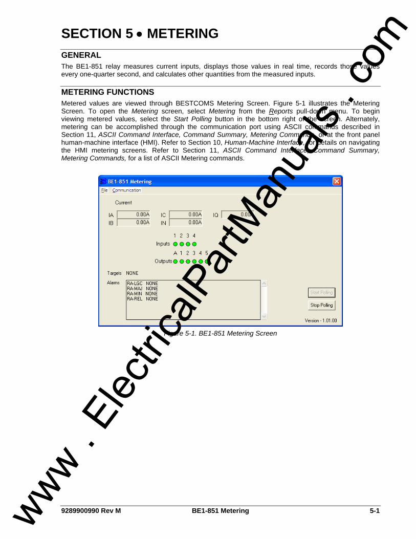
9289900990 Rev M BE1-851 Metering 5-1
SECTION 5 • METERING GENERAL The BE1-851 relay measures current inputs, displays those values in real time, records those values every one-quarter second, and calculates other quantities from the measured inputs.
METERING FUNCTIONS Metered values are viewed through BESTCOMS Metering Screen. Figure 5-1 illustrates the Metering Screen. To open the Metering screen, select Metering from the Reports pull-down menu. To begin viewing metered values, select the Start Polling button in the bottom right of the screen. Alternately, metering can be accomplished through the communication port using ASCII commands described in Section 11, ASCII Command Interface, Command Summary, Metering Commands, or at the front panel human-machine interface (HMI). Refer to Section 10, Human-Machine Interface, for details on navigating the HMI metering screens. Refer to Section 11, ASCII Command Interface, Command Summary, Metering Commands, for a list of ASCII Metering commands.
Figure 5-1. BE1-851 Metering Screen
www . El
ectric
alPar
tMan
uals
. com

5-2 BE1-851 Metering 9289900990 Rev M
This page intentionally left blank.
www . El
ectric
alPar
tMan
uals
. com
9289900990 Rev M BE1-851 Reporting and Alarm Functions i
SECTION 6 • REPORTING AND ALARM FUNCTIONS
TABLE OF CONTENTS SECTION 6 • REPORTING AND ALARM FUNCTIONS .......................................................................... 6-1
GENERAL.............................................................................................................................................. 6-1 RELAY IDENTIFIER INFORMATION.................................................................................................... 6-1 CLOCK................................................................................................................................................... 6-2
IRIG Port............................................................................................................................................. 6-2 Setting the Clock Function ................................................................................................................. 6-2 Reading and Setting the Clock........................................................................................................... 6-3 Alternate DST (Daylight Saving Time) Settings ................................................................................. 6-3
GENERAL STATUS REPORTING ........................................................................................................ 6-4 General Status Report........................................................................................................................ 6-4 Other RG Commands......................................................................................................................... 6-6
DEMAND FUNCTIONS ......................................................................................................................... 6-6 Demand Reporting ............................................................................................................................. 6-6
BREAKER MONITORING ..................................................................................................................... 6-9 Breaker Status Reporting ................................................................................................................... 6-9 Breaker Duty Monitoring................................................................................................................... 6-11 Breaker Alarms................................................................................................................................. 6-13
TRIP CIRCUIT MONITOR ................................................................................................................... 6-16 FAULT REPORTING ........................................................................................................................... 6-18
Logic Expressions for Fault Reporting ............................................................................................. 6-18 Targets ............................................................................................................................................. 6-19 Fault Summary Reports ................................................................................................................... 6-21 Oscillographic Records .................................................................................................................... 6-24
SEQUENCE OF EVENTS RECORDER.............................................................................................. 6-26 Retrieving SER Information Using BESTCOMS .............................................................................. 6-26 Retrieving SER Information Using ASCII Commands...................................................................... 6-27
ALARMS FUNCTION........................................................................................................................... 6-27 Relay Trouble Alarms....................................................................................................................... 6-27 Major, Minor, and Logic Programmable Alarms............................................................................... 6-28 Links between Programmable Alarms and BESTlogic .................................................................... 6-31
HARDWARE AND SOFTWARE VERSION......................................................................................... 6-32 SETTINGS COMPARE........................................................................................................................ 6-33
Figures Figure 6-1. General Operation Screen, General Information Tab............................................................. 6-1 Figure 6-2. Reporting and Alarms Screen, Clock Display Mode Tab........................................................ 6-2 Figure 6-3. Reporting and Alarms Screen, Demands Tab ........................................................................ 6-8 Figure 6-4. BESTlogic Function Element Screen, Breaker Status.......................................................... 6-10 Figure 6-5. Reporting and Alarms Screen, Breaker Monitoring Tab....................................................... 6-12 Figure 6-6. BESTlogic Function Element Screen, Breaker Duty Monitoring........................................... 6-12 Figure 6-7. Reporting and Alarms Screen, Breaker Monitoring Tab....................................................... 6-14 Figure 6-8. Protective Fault Analysis....................................................................................................... 6-15 Figure 6-9. Trip Circuit Voltage and Continuity Monitor .......................................................................... 6-17 Figure 6-10. TCM with Other Devices ..................................................................................................... 6-17 Figure 6-11. BESTlogic Function Element Screen, Fault Recording ...................................................... 6-19 Figure 6-12. Reporting and Alarms Screen, Fault Recording Tab .......................................................... 6-20 Figure 6-13. View/Download Relay Fault Files Screen........................................................................... 6-21 Figure 6-14. View/Download Relay Fault Files ....................................................................................... 6-25 Figure 6-15. Browse for Folder Screen ................................................................................................... 6-25 Figure 6-16. Fault Record Filenames...................................................................................................... 6-25 Figure 6-17. View/Download Relay Fault Files Screen........................................................................... 6-26 Figure 6-18. Reporting and Alarms Screen, Alarms Tab ........................................................................ 6-30 Figure 6-19. Programmable Alarm Function ........................................................................................... 6-31 www .
Elec
tricalP
artM
anua
ls . c
om
ii BE1-851 Reporting and Alarm Functions 9289900990 Rev M
Figure 6-20. BESTlogic Function Element Screen Alarm Reset Logic ................................................... 6-32 Figure 6-21. Settings Compare Setup Dialog Box .................................................................................. 6-33 Figure 6-22. Settings Compare Dialog Box............................................................................................. 6-33
Tables Table 6-1. Circuit Identification Parameters .............................................................................................. 6-1 Table 6-2. Time and Date Format Settings ............................................................................................... 6-3 Table 6-3. Logic Variable Status Report Format for Sensing Input Type H Relays.................................. 6-5 Table 6-4. Logic Variable Status Report Format for Sensing Input Type G Relays.................................. 6-5 Table 6-5. SG-DI Command Settings........................................................................................................ 6-9 Table 6-6. Breaker Duty Monitoring Settings .......................................................................................... 6-13 Table 6-7. Breaker Alarms Settings......................................................................................................... 6-14 Table 6-8. Legend for Figure 6-8............................................................................................................. 6-16 Table 6-9. Fault Recording Trigger Settings ........................................................................................... 6-19 Table 6-10. Targets as Displayed............................................................................................................ 6-20 Table 6-11. Oscillographic Hardware Support ........................................................................................ 6-24 Table 6-12. Relay Trouble Alarms........................................................................................................... 6-28 Table 6-13. Programmable Alarms.......................................................................................................... 6-28 Table 6-14. Programmable Alarm Settings ............................................................................................. 6-30
Equations Equation 6-1. Demand Current Equation .................................................................................................. 6-7 Equation 6-2. Exponential Response Constant......................................................................................... 6-7 Equation 6-3. Step Change Demand Calculation...................................................................................... 6-7 Equation 6-4. Dmax Set by Number of Operations ................................................................................. 6-11 Equation 6-5. Dmax Set Using Square Root Factor................................................................................ 6-11
www . El
ectric
alPar
tMan
uals
. com
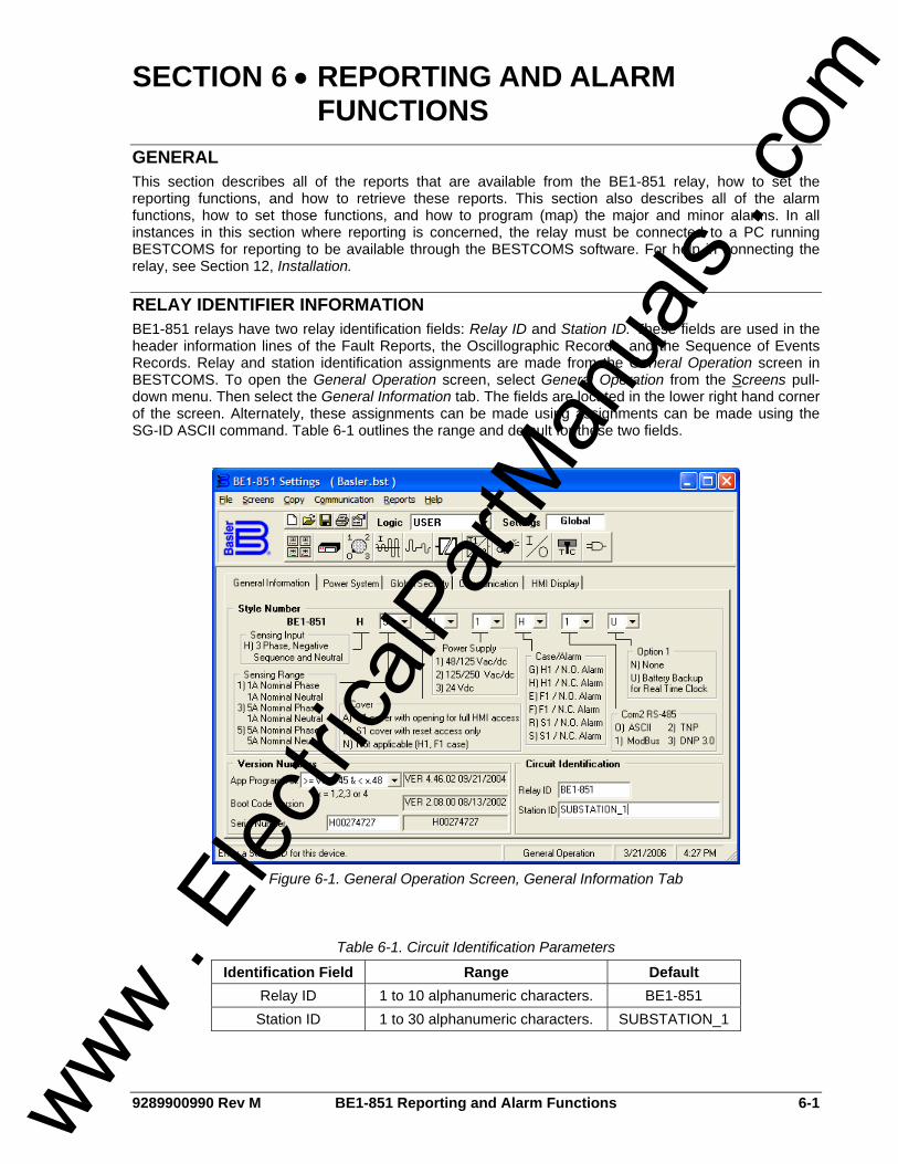
9289900990 Rev M BE1-851 Reporting and Alarm Functions 6-1
SECTION 6 • REPORTING AND ALARM FUNCTIONS
GENERAL This section describes all of the reports that are available from the BE1-851 relay, how to set the reporting functions, and how to retrieve these reports. This section also describes all of the alarm functions, how to set those functions, and how to program (map) the major and minor alarms. In all instances in this section where reporting is concerned, the relay must be connected to a PC running BESTCOMS for reporting to be available through the BESTCOMS software. For help in connecting the relay, see Section 12, Installation.
RELAY IDENTIFIER INFORMATION BE1-851 relays have two relay identification fields: Relay ID and Station ID. These fields are used in the header information lines of the Fault Reports, the Oscillographic Records, and the Sequence of Events Records. Relay and station identification assignments are made from the General Operation screen in BESTCOMS. To open the General Operation screen, select General Operation from the Screens pull-down menu. Then select the General Information tab. The fields are located in the lower right hand corner of the screen. Alternately, these assignments can be made using assignments can be made using the SG-ID ASCII command. Table 6-1 outlines the range and default for these two fields.
Figure 6-1. General Operation Screen, General Information Tab
Table 6-1. Circuit Identification Parameters
Identification Field Range Default Relay ID 1 to 10 alphanumeric characters. BE1-851 Station ID 1 to 30 alphanumeric characters. SUBSTATION_1
www .
Elec
tricalP
artM
anua
ls . c
om
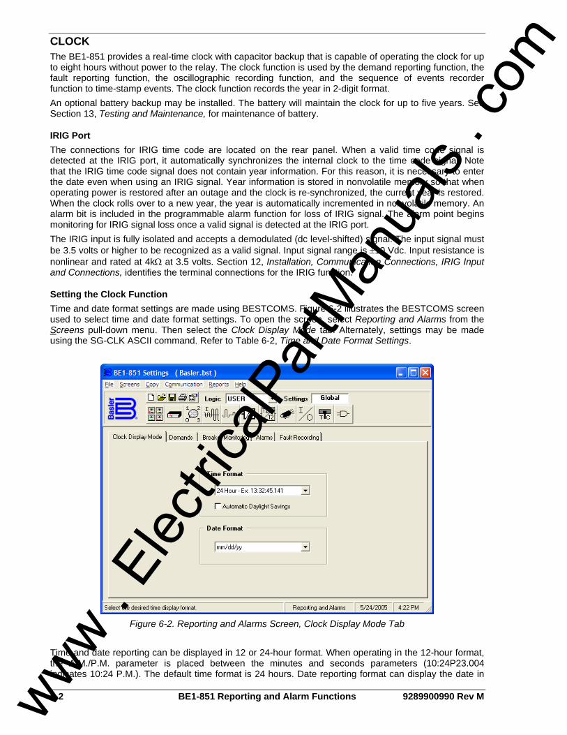
6-2 BE1-851 Reporting and Alarm Functions 9289900990 Rev M
CLOCK The BE1-851 provides a real-time clock with capacitor backup that is capable of operating the clock for up to eight hours without power to the relay. The clock function is used by the demand reporting function, the fault reporting function, the oscillographic recording function, and the sequence of events recorder function to time-stamp events. The clock function records the year in 2-digit format. An optional battery backup may be installed. The battery will maintain the clock for up to five years. See Section 13, Testing and Maintenance, for maintenance of battery.
IRIG Port The connections for IRIG time code are located on the rear panel. When a valid time code signal is detected at the IRIG port, it automatically synchronizes the internal clock to the time code signal. Note that the IRIG time code signal does not contain year information. For this reason, it is necessary to enter the date even when using an IRIG signal. Year information is stored in nonvolatile memory so that when operating power is restored after an outage and the clock is re-synchronized, the current year is restored. When the clock rolls over to a new year, the year is automatically incremented in nonvolatile memory. An alarm bit is included in the programmable alarm function for loss of IRIG signal. The alarm point begins monitoring for IRIG signal loss once a valid signal is detected at the IRIG port. The IRIG input is fully isolated and accepts a demodulated (dc level-shifted) signal. The input signal must be 3.5 volts or higher to be recognized as a valid signal. Input signal range is ±10 Vdc. Input resistance is nonlinear and rated at 4kΩ at 3.5 volts. Section 12, Installation, Communication Connections, IRIG Input and Connections, identifies the terminal connections for the IRIG function.
Setting the Clock Function Time and date format settings are made using BESTCOMS. Figure 6-2 illustrates the BESTCOMS screen used to select time and date format settings. To open the screen, select Reporting and Alarms from the Screens pull-down menu. Then select the Clock Display Mode tab. Alternately, settings may be made using the SG-CLK ASCII command. Refer to Table 6-2, Time and Date Format Settings.
Figure 6-2. Reporting and Alarms Screen, Clock Display Mode Tab
Time and date reporting can be displayed in 12 or 24-hour format. When operating in the 12-hour format, the A.M./P.M. parameter is placed between the minutes and seconds parameters (10:24P23.004 indicates 10:24 P.M.). The default time format is 24 hours. Date reporting format can display the date in
www . El
ectric
alPar
tMan
uals
. com

9289900990 Rev M BE1-851 Reporting and Alarm Functions 6-3
mm/dd/yy or dd/mm/yy format. The default date format is mm/dd/yy. The relay clock can also accommodate daylight saving time changes. Automatic daylight saving time adjustments are optional and they are disabled by default.
Table 6-2. Time and Date Format Settings
Parameter Range Default
Time Format 12 (12 hour format) 24 (24 hour format) 24
Date Format m (mm-dd-yy) d (dd-mm-yy) M
Automatic Daylight Savings 0 (daylight saving time disabled) 1 (daylight saving time enabled) 0
Reading and Setting the Clock Clock information can be viewed and set at the front panel human-machine interface (HMI) and through the communication ports using ASCII commands or BESTCOMS. Write access to reports is required to set the clock at the HMI and communication ports. An alarm point is provided in the programmable alarms to detect when the relay has powered up and the clock has not been set. Time and date information is read and set at HMI Screen 4.5, through the communication ports using the RG-DATE and RG-TIME ASCII commands, and through BESTCOMS by selecting the Communication pull-down menu and then selecting Set Date and Time.
Alternate DST (Daylight Saving Time) Settings Alternate DST settings are necessary when not using a time zone in the United States. These settings can only be adjusted using ASCII commands. They cannot be set with BESTCOMS or through the HMI. The following serial commands must be entered in the order shown with all parameters entered for the alternate DST settings to function properly.
Select Floating Date or Fixed Date Configuration SG-DST=1 (Floating Date) or 2 (Fixed Date) Example: SG-DST=2 selects Fixed Date configuration
If using Floating Date Configuration SG-DSTSTART=Mo,D,H,M,O and SG-DSTSTOP=Mo,D,H,M,O Mo (Month) = 1 (January) to 12 (December) D (Day of Week) = 0 (Sunday) to 6 (Saturday) H (Hour) = 0 (12:00am) to 23 (11:00pm) M (Minutes) = 0 to 59 O (Occurrence) = 1 (First D (Day) of the month) to 5 (Fifth D (Day) of the month)
Examples: SG-DSTSTART=5,3,2,15,3 is the 3rd Wednesday in May at 2:15am SG-DSTSTOP=7,6,5,45,2 is the 2nd Saturday in July at 5:45am
If using Fixed Date Configuration SG-DSTSTART=Mo,D,H,M,O and SG-DSTSTOP=Mo,D,H,M,O Mo (Month) = 1 (January) to 12 (December) D (Day of Month) = 1 to 31 H (Hour) = 0 (12:00am) to 23 (11:00pm) M (Minutes) = 0 to 59 O (Occurrence) = 0 (Not used for Fixed Date configuration)
Examples: SG-DSTSTART=5,20,2,15,0 is May 20th at 2:15am SG-DSTSTOP=7,10,15,30,0 is July 10th at 3:30pm
www . El
ectric
alPar
tMan
uals
. com

6-4 BE1-851 Reporting and Alarm Functions 9289900990 Rev M
UTC (Coordinated Universal Time) SG-UTC=M,R,B M (Offset from UTC in Minutes) = -720 to 840 R (Reference Time) = 0 (Local) or 1 (UTC) B (Bias: amount of minutes to adjust DST) = 0 to 300
Example: SG-UTC=0,0,60 for UTC offset of 0 minutes, local reference for the DST change, and adjustment amount of 60 minutes
The RG-DST command reports start and stop times and dates for Daylight Saving Time referenced to local time. Refer to Section 11, ASCII Command Interface, for a list of all ASCII commands.
GENERAL STATUS REPORTING BE1-851 relays have extensive capabilities for reporting relay status. This is important for determining the health and status of the system for diagnostics and troubleshooting. Throughout this manual, reference is made to the RG-STAT (report general – status) report and the appropriate HMI screens for determining the status of various functions.
General Status Report A General Status Report is available through the communication ports using the RG-STAT command. This report lists all of the information required to determine the status of the relay. An example of a typical general status report follows. In the explanation of what each line represents, cross-references are made to the corresponding HMI screens that contain that data. >RG-STAT INPUT(1234) STATUS : 0000 OUTPUT(A12345) STATUS : 000000 CO-OUT(A12345) STATUS : LLLLLL CO-43/143/243/343 STATUS : 0000 CO-101(101SC) STATUS : AFTER CLOSE(1) CO-GROUP STATUS : L ACTIVE LOGIC STATUS : USER LOGIC VAR(00-31) STATUS : 00000000 00000000 00000000 00000000 LOGIC VAR(32-63) STATUS : 00000000 00000000 00000010 00011000 RECLOSER(79) STATUS : OFF ACTIVE GROUP STATUS : 0 BREAKER(52) STATUS : CLOSED DIAG/ALARM STATUS : 0 RELAY, 0 LOGIC, 0 MAJOR, 0 MINOR
Input (1234) This line reports the status of contact sensing inputs IN1, IN2, IN3, and IN4. Input information is available at HMI Screen 1.5.1. 0 indicates a de-energized input and 1 indicates an energized input. See Section 3, Input and Output Functions, for more information about contact sensing input operation.
Output (A12345) Current output contact status is reported on this line. This information is also available at HMI Screen 1.5.2. 0 indicates a de-energized output and 1 indicates an energized output. More information about output contact operation is available in Section 3, Input and Output Functions.
CO-OUT (A12345) This line reports the logic override of the output contacts. Logic override status is reported at HMI Screen 1.5.3. Section 3, Input and Output Functions, provides more information about overriding output contacts.
CO-43/143/243/343 Virtual switch function status is reported on this line. This information is also available at HMI Screen 1.5.4. See Section 4, Protection and Control, for more information about virtual switch operation.
www . El
ectric
alPar
tMan
uals
. com

9289900990 Rev M BE1-851 Reporting and Alarm Functions 6-5
CO-101 (101SC) This line reports the status of the virtual breaker control switch slip-contact output. More information about the virtual breaker control switch is available in Section 4, Protection and Control, Virtual Switches.
CO-Group The logic override status of the setting group selection function is reported on this line. For more information about this function, refer to Section 4, Protection and Control, Setting Groups.
Active Logic This line reports the name of the active logic scheme. The active logic scheme name can be viewed at HMI Screen 5 and with the SL-N command. See Section 7, BESTlogic Programmable Logic, Logic Schemes, for more information about this function.
Logic Var (00-31), Logic Var (32-63) These two lines report the status of each BESTlogic variable. These lines can be entered into Table 6-3 and Table 6-4 to determine the status of each logic variable. Section 7, BESTlogic Programmable Logic, provides more information about BESTlogic variables.
Table 6-3. Logic Variable Status Report Format for Sensing Input Type H Relays
5 0 TPT
150TPT
50TNT
150TNT
50TQT
150TQT
BFT
51PT
51NT
51QT
50TPPU
150TPPU
50TNPU
150TNPU
50TQPU
150TQPU
BFPU
51PPU
51NPU
51QPU
62
162
43
143
243
343
79C
79RNG
79LO
79F
79SCB
SPARE
00
01
02
03
04
05
06
07
08
09
10
11
12
13
14
15
16
17
18
19
20
21
22
23
24
25
26
27
28
29
30
31
VOA
VO1
VO2
VO3
VO4
VO5
VO6
VO7
VO8
VO9
VO10
VO11
VO12
VO13
VO14
VO15
IN1
IN2
IN3
IN4
101T
101C
101SC
RSTKEY
ALMLGC
ALMMAJ
ALMMIN
OUT1MON
SG0
SG1
SG2
SG3
32
33
34
35
36
37
38
39
40
41
42
43
44
45
46
47
48
49
50
51
52
53
54
55
56
57
58
59
60
61
62
63
Table 6-4. Logic Variable Status Report Format for Sensing Input Type G Relays
5 0 TPT
150TPT
50TNT
150TNT
250TNT
350TNT
BFT
51PT
51NT
51QT
50TPPU
150TPPU
50TNPU
150TNPU
250TNPU
350TNPU
BFPU
51PPU
51NPU
51QPU
62
162
43∗
143∗
243∗
343∗
79C
79RNG
79LO
79F
79SCB
SPARE
00
01
02
03
04
05
06
07
08
09
10
11
12
13
14
15
16
17
18
19
20
21
22
23
24
25
26
27
28
29
30
31
www . El
ectric
alPar
tMan
uals
. com

6-6 BE1-851 Reporting and Alarm Functions 9289900990 Rev M
VOA
VO1
VO2
VO3
VO4
VO5
VO6
VO7
VO8
VO9
VO10
VO11
VO12
VO13
VO14
VO15
IN1
IN2
IN3
IN4
101T
101C
101SC
RSTKEY
ALMLGC
ALMMAJ
ALMMIN
OUT1MON
SG0
SG1
SG2
SG3
32
33
34
35
36
37
38
39
40
41
42
43
44
45
46
47
48
49
50
51
52
53
54
55
56
57
58
59
60
61
62
63
∗ The following applies when style option 1 is V or W.
Logic Bit Function22 262 23 362 24 43 25 143
See Tables 7-1 and 7-2, Logic Variable Names and Descriptions, for a cross-reference of each BESTlogic bit.
Recloser (79) The status of the recloser is reported on this line. HMI Screen 1.1 also reports this information. More information about the recloser function is available in Section 4, Protection and Control Functions.
Active Group The active group is indicated on this line. HMI Screen 1.5.5 also provides this information. See Section 4, Protection and Control, for more information about setting groups.
Breaker (52) This line reports the state of the breaker. This information is also available at HMI Screen 1.5.6. More information about breaker status is provided in the Breaker Monitoring subsection.
Diag/Alarm This line reports the status of the Relay Trouble Alarm, Major Alarm, Minor Alarm, and Logic Alarm. The status of these alarms can be viewed at HMI Screen 1.3. Front panel LEDs also indicate the status of the Relay Trouble Alarm, Minor Alarm, and Major Alarm. Alarm status is also available through the communication ports. The SA-MIN command reports the Minor Alarm status, the SA-MAJ command reports the Major Alarm status, and the SA-LGC command reports the Logic Alarm status.
Other RG Commands There are several other RG commands in addition to the RG-STAT command. These include RG-TIME, RG-DATE, RG-TARG, and RG-VER. These commands are covered in detail in respective paragraphs in this section. As with other commands, a combination read command is available to read several items in a group. If the command RG is entered by itself, the relay reports the time, date, target information, and other reports in the following example. RG-VER and RG-STAT commands have multiple line outputs and these are not read at the RG command.
DEMAND FUNCTIONS
Demand Reporting The demand reporting function continuously calculates demand values for the three-phase currents, neutral current, and negative-sequence current. Demand values are recorded with time stamps for Peak Since Reset, Yesterday’s Peak, and Today’s Peak. Programmable alarm points can be set to alarm if thresholds are exceeded for overload and unbalanced loading conditions.
www . El
ectric
alPar
tMan
uals
. com

9289900990 Rev M BE1-851 Reporting and Alarm Functions 6-7
Demand Calculation and Reporting An algorithm in the demand reporting function digitally simulates a thermal or exponential response. An exponential algorithm computes demand values with the demand interval or response period defined as the time taken by the meter to reach 90 percent of the final value for a step change in the current being measured. Demand interval can be set independently for the phase, neutral, and negative-sequence demand calculations. The reactive power and power demand intervals always match the phase demand interval setting. The following equation is used to calculate demand current:
( )11 −−+−= nnn DIMIKDIDI Equation 6-1. Demand Current Equation
Where:
nDI = Demand current for sampling period n ( nt = 15 seconds)
nMI = Average metered current value for sampling period n
K = Exponential response constant
The following equation is used for K :
⎟⎟
⎠
⎞
⎜⎜
⎝
⎛−= − I
n
Tt
eK 434.01 Equation 6-2. Exponential Response Constant
Where:
IT = Demand interval (programmed with SG-DI command)
nt = Fixed demand update rate of 15 seconds
Demand is calculated for a step change in current by the following equation:
MIeDI I
n
Tt
⎟⎟
⎠
⎞
⎜⎜
⎝
⎛−= − 434.01 Equation 6-3. Step Change Demand Calculation
Demand calculation example for a step change in current: If the current steps from 0 to 1,000 amperes, then the peak demand will change from 0 to 900 amperes after one demand interval ( )ITt = .
Each time that the value in the current demand register is updated, it is compared to the values stored in the Peak Since Reset and the Today’s Peak registers. If the new demand is greater, the new value and time stamp is entered into the appropriate registers. In addition, the demand reporting function keeps an additional set of registers for Yesterday’s Peak. Each day at midnight, the demand reporting function replaces the values and time stamps stored in Yesterday’s Peak registers with the values and time stamps from Today’s Peak registers. It then starts recording new information in Today’s Peak registers. Demand registers are stored in volatile memory. Today’s Peak and Yesterday’s Peak registers are read only. Values in the Peak Since Reset registers can be reset to zero or preset to a predetermined value. For example, if some loads will be switched to remove a feeder from service and you do not want the abnormal loading to affect the Peak Since Reset
www . El
ectric
alPar
tMan
uals
. com
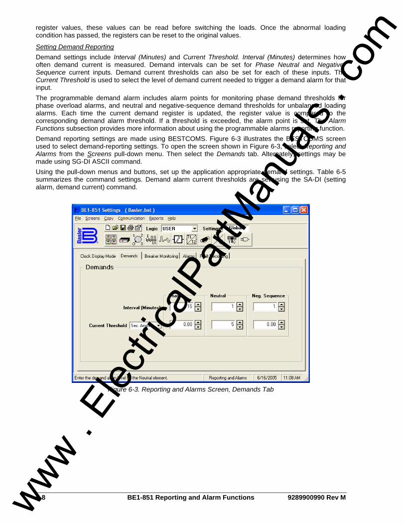
6-8 BE1-851 Reporting and Alarm Functions 9289900990 Rev M
register values, these values can be read before switching the loads. Once the abnormal loading condition has passed, the registers can be reset to the original values.
Setting Demand Reporting Demand settings include Interval (Minutes) and Current Threshold. Interval (Minutes) determines how often demand current is measured. Demand intervals can be set for Phase Neutral and Negative-Sequence current inputs. Demand current thresholds can also be set for each of these inputs. The Current Threshold is used to select the level of demand current needed to trigger a demand alarm for that input. The programmable demand alarm includes alarm points for monitoring phase demand thresholds for phase overload alarms, and neutral and negative-sequence demand thresholds for unbalanced loading alarms. Each time the current demand register is updated, the register value is compared to the corresponding demand alarm threshold. If a threshold is exceeded, the alarm point is set. The Alarm Functions subsection provides more information about using the programmable alarms reporting function. Demand reporting settings are made using BESTCOMS. Figure 6-3 illustrates the BESTCOMS screen used to select demand-reporting settings. To open the screen shown in Figure 6-3, select Reporting and Alarms from the Screens pull-down menu. Then select the Demands tab. Alternately, settings may be made using SG-DI ASCII command. Using the pull-down menus and buttons, set up the application appropriate demand settings. Table 6-5 summarizes the command settings. Demand alarm current thresholds are set using the SA-DI (setting alarm, demand current) command.
Figure 6-3. Reporting and Alarms Screen, Demands Tab
www . El
ectric
alPar
tMan
uals
. com

9289900990 Rev M BE1-851 Reporting and Alarm Functions 6-9
Table 6-5. SG-DI Command Settings
Range Setting
5 A 1 A Increment Unit of
Measure Default
Current Threshold 0 = Disabled
0.5 – 16.0 0 = Disabled
0.1 – 3.2 0.01for 0.1 to 9.99 0.1 for 10.0 to 16.0
Sec. Amps Pri. Amps
Per U Amps % Amps
0
Phase 0 to 60 1 Minutes 15
Neutral 0 to 60 1 Minutes 1 Interval (minutes)
Negative-Sequence 0 to 60 1 Minutes 1
Example 1. Make the following demand settings. See Figure 6-3. Interval Minutes Phase: 15 Interval Minutes Neutral: 1 Interval Minutes Negative-Sequence: 1 Current Threshold (Sec. Amps) Phase: 0.00 Current Threshold (Sec. Amps) Neutral: 5.00 Current Threshold (Sec. Amps) Neg. Seq.: 0.00
Retrieving Demand Reporting Information Values and time stamps in the demand registers are reported in primary amperes. They can be read at the front panel HMI and through the communication ports. Today’s Peak, Yesterday’s Peak, and Peak Since Reset demand values are accessed through HMI Screen 4.4, DEMAND REPORTS. Demand values viewed at the HMI can be reset by pressing the Reset key. When the Reset key is pressed, the viewed register value is set to zero and then updated on the next processing loop with the currently calculated demand value. No write access is needed to reset demand register values at the HMI. It is also possible to preset a value into the Peak Since Demand registers. Pressing the Edit key can do this. Write access to the Reports functional area is required to preset values at the HMI. Values and time stamps in the demand registers can also be read through the communication ports by using the RD (report demands) command. Demand information specific to current, can be obtained by including an object name with the command function (R) and subgroup (D). Today’s Peak, Yesterday’s Peak, and Peak Since Reset information for current is available using the RD-TI, RD-YI, and RD-PI commands.
BREAKER MONITORING Breaker monitoring helps manage equipment inspection and maintenance expenses by providing extensive monitoring and alarms for the circuit breaker. Breaker monitoring functions include breaker status and operations counter reporting, fault current interruption duty monitoring and trip-speed monitoring. Each function can be set up as a programmable alarm. The Alarms Function subsection has more information about the use of programmable alarms. The breaker trip circuit voltage and continuity monitor is a related function and is described in the Trip Circuit Monitor subsection.
Breaker Status Reporting The breaker status monitoring function monitors the position of the breaker for reporting purposes. Opening breaker strokes are also counted and recorded in the breaker operations counter register. Circuit breaker status is also used by the breaker trip circuit voltage and continuity monitor. The Trip Circuit Monitor subsection provides more details.
www . El
ectric
alPar
tMan
uals
. com
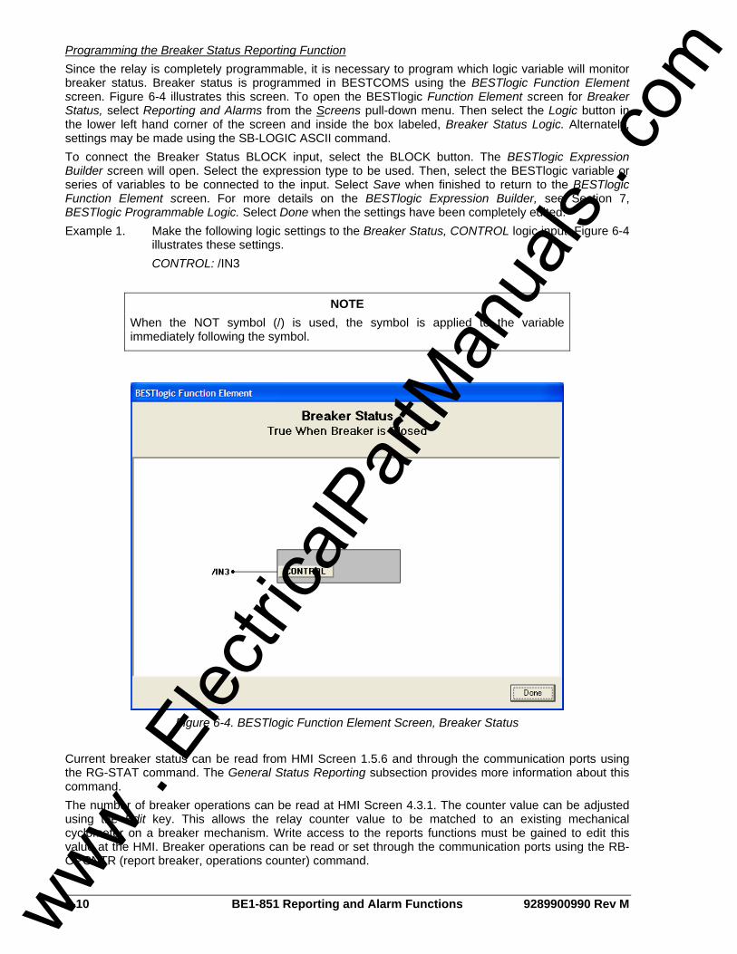
6-10 BE1-851 Reporting and Alarm Functions 9289900990 Rev M
Programming the Breaker Status Reporting Function Since the relay is completely programmable, it is necessary to program which logic variable will monitor breaker status. Breaker status is programmed in BESTCOMS using the BESTlogic Function Element screen. Figure 6-4 illustrates this screen. To open the BESTlogic Function Element screen for Breaker Status, select Reporting and Alarms from the Screens pull-down menu. Then select the Logic button in the lower left hand corner of the screen and inside the box labeled, Breaker Status Logic. Alternately, settings may be made using the SB-LOGIC ASCII command. To connect the Breaker Status BLOCK input, select the BLOCK button. The BESTlogic Expression Builder screen will open. Select the expression type to be used. Then, select the BESTlogic variable or series of variables to be connected to the input. Select Save when finished to return to the BESTlogic Function Element screen. For more details on the BESTlogic Expression Builder, see Section 7, BESTlogic Programmable Logic. Select Done when the settings have been completely edited. Example 1. Make the following logic settings to the Breaker Status, CONTROL logic input. Figure 6-4
illustrates these settings. CONTROL: /IN3
Figure 6-4. BESTlogic Function Element Screen, Breaker Status
Current breaker status can be read from HMI Screen 1.5.6 and through the communication ports using the RG-STAT command. The General Status Reporting subsection provides more information about this command. The number of breaker operations can be read at HMI Screen 4.3.1. The counter value can be adjusted using the Edit key. This allows the relay counter value to be matched to an existing mechanical cyclometer on a breaker mechanism. Write access to the reports functions must be gained to edit this value at the HMI. Breaker operations can be read or set through the communication ports using the RB-OPCNTR (report breaker, operations counter) command.
NOTE When the NOT symbol (/) is used, the symbol is applied to the variable immediately following the symbol.
www . El
ectric
alPar
tMan
uals
. com

9289900990 Rev M BE1-851 Reporting and Alarm Functions 6-11
The breaker operations counter can be monitored to give an alarm when the value exceeds a threshold. See Breaker Alarms in this section for more information about this feature.
Breaker Duty Monitoring When the breaker opens, the current interrupted in each pole of the circuit breaker is accumulated by the breaker duty monitor. Breaker opening is defined by the breaker status monitoring function. Figure 6-8 illustrates breaker status during a fault and protective trip. Table 6-8 serves as a legend for the call-outs of Figure 6-8. Every time the breaker trips, the breaker duty monitor updates two sets of registers for each pole of the breaker. In the Accumulated I Duty registers, the breaker duty monitor adds the measured current in primary amperes. In the Accumulated I2 Duty registers, the function adds the measured current squared in primary amperes. The user selects which of the two sets of duty registers are reported and monitored when setting up the breaker duty monitor. Even though duty register values are calculated and stored in primary amperes or primary amperes-squared, the duty value is reported as a percent of maximum. The user sets the value that the relay will use for 100 percent duty (Dmax). The value set for maximum duty is used directly for reporting the accumulated I Duty. The square of the value set for maximum duty is used for reporting the accumulated I2 Duty. If the breaker monitoring mode is set to sum I (not I2), the relay sums the sum of the currents that are interrupted and will set the breaker duty alarm when the sum passes that breaker duty setting (Dmax). The approach to set Dmax is to select the maximum number of operations at some current level and enter a Dmax calculated by the equation:
( )operations*#ImaxD erruptint= Equation 6-4. Dmax Set by Number of Operations
The setting is in terms of primary amps (the relay multiples by the CT ratio before doing calculations). If the breaker-monitoring mode is set to sum I2, the relay internally squares the setting that is entered for Dmax. The relay sums the square of the currents interrupted and it will set the breaker duty alarm when the sum exceeds the square of the Dmax setting. The approach to set Dmax is to select the maximum number of operations at some current level and enter a Dmax calculated by the equation:
( ) 502 .erruptint operations*#ImaxD = Equation 6-5. Dmax Set Using Square Root Factor
Again, the setting is in terms of primary amps. The 0.5 power (i.e., square root factor) shown above for the Dmax setting is to compensate for the fact that the relay internally squares the Dmax that is entered. When testing the relay by injecting currents into the relay, the values in the duty registers should be read and recorded before the start of testing. Once testing is complete and the relay is returned to service, the registers should be reset to the original pre-test values. A block accumulation logic input may be used when testing so that simulated breaker duty is not added to the duty registers. The Block Accumulation Logic function is an OR logic term (e.g., IN1 or VO7) which blocks the breaker monitoring logic when TRUE (1). Block Accumulation Logic is set to zero to disable blocking. When breaker monitoring is blocked (logic expression equals 1), breaker duty is not accumulated.
Setting the Breaker Duty Monitoring Function Breaker Duty Monitoring settings are made using BESTCOMS. Figure 6-5 illustrates the BESTCOMS screen used to select settings for the Breaker Duty Monitoring function. To open the Reporting and Alarms screen, select Reporting and Alarms from the Screens pull-down menu. Then select the Breaker Monitoring tab. Settings may also be made using the SB-DUTY ASCII command. At the top left of the screen is a pull-down menu labeled Logic. This menu allows viewing of the BESTlogic settings for each preprogrammed logic scheme. User must be selected on this menu in order to allow changes to be made to the mode and inputs of the function/element. Using the pull-down menus and buttons, make the application appropriate settings to the Breaker Duty Monitoring function. Table 6-6 summarizes the Breaker Duty Monitoring settings.
www . El
ectric
alPar
tMan
uals
. com
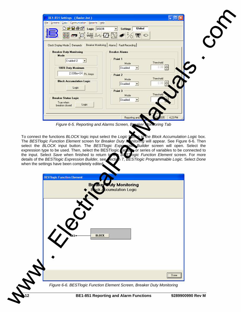
6-12 BE1-851 Reporting and Alarm Functions 9289900990 Rev M
Figure 6-5. Reporting and Alarms Screen, Breaker Monitoring Tab
To connect the functions BLOCK logic input select the Logic button in the Block Accumulation Logic box. The BESTlogic Function Element screen for Breaker Duty Monitoring will appear. See Figure 6-6. Then select the BLOCK input button. The BESTlogic Expression Builder screen will open. Select the expression type to be used. Then, select the BESTlogic variable or series of variables to be connected to the input. Select Save when finished to return to the BESTlogic Function Element screen. For more details of the BESTlogic Expression Builder, see Section 7, BESTlogic Programmable Logic. Select Done when the settings have been completely edited.
Figure 6-6. BESTlogic Function Element Screen, Breaker Duty Monitoring
www . El
ectric
alPar
tMan
uals
. com

9289900990 Rev M BE1-851 Reporting and Alarm Functions 6-13
Table 6-6. Breaker Duty Monitoring Settings
Setting Range/Purpose Default
Mode 0 = Disabled 1 = Enabled I 2 = Enabled I2
0
100% Duty Maximum
0 to 4.2e+7 The Dmax parameter represents the maximum duty that the breaker contacts can withstand before needing service. Dmax is programmed in primary amperes using exponential floating-point format.
0
Block Accumulation
Logic
OR logic term (e.g., IN1 or VO7) that blocks the breaker monitoring logic when TRUE (1). A setting of 0 disabled blocking (breaker operation are no longer counted).
0
Example 1. Make the following settings to the Breaker Duty Monitoring Function. Refer to Figure 6-5
and Figure 6-6. Mode: Enabled I2 100% Duty Maximum: 2.000e+04 Block Accumulation Logic: IN3
Retrieving Breaker Duty Information Breaker duty values can be read at HMI Screen 4.3.2. Duty values can be changed by using the front panel Edit key. Write access to reports is required to edit breaker duty values. Duty values can also be read or changed through the communication ports using the RB-DUTY command.
Breaker Clearing Time Monitoring The breaker clearing time monitor tracks the time from when a <TRIP> logic expression of the “Fault Recording” feature (SG-TRIGGER=<TRIP>,<PU>,<LOGIC>) goes TRUE, until the fast current dropout detector is FALSE (current = 0 amps in all three phases). The trip output (i.e., 51PT, 51NT, etc.) of any protective element can be programmed to the Fault Recording <TRIP> logic expression. Therefore, when the trip output of the protective element goes TRUE, the <TRIP> logic expression goes TRUE. This time is reported as a line in the fault summary reports. See the Fault Reporting subsection for more information about the TRIP logic expression and Fault Summary Reports. Breaker clearing time can be monitored to give an alarm when the value exceeds a threshold. The following Breaker Alarms subsection provides more information about this feature.
Breaker Alarms Three alarm points are included in the programmable alarms for checking breaker-monitoring functions. Each alarm point can be programmed to monitor any of the three breaker monitoring functions: operations counter, interruption duty, or clearing time. An alarm threshold can be programmed to monitor each function. Alternately, three different thresholds can be programmed to monitor one of the monitored functions. Breaker Alarms settings are made using BESTCOMS. Figure 6-7 illustrates the BESTCOMS screen used to select settings for the Breaker Alarms function. To open the Reporting and Alarms screen, select Reporting and Alarms from the Screens pull-down menu. Then select the Breaker Monitoring tab. Settings may also be made using the SB-BKR ASCII command. At the top left of the screen is a pull-down menu labeled Logic. This menu allows viewing of the BESTlogic settings for each preprogrammed logic scheme. User must be selected on this menu in order to allow changes to be made to the mode and inputs of the function.
www . El
ectric
alPar
tMan
uals
. com

6-14 BE1-851 Reporting and Alarm Functions 9289900990 Rev M
Figure 6-7. Reporting and Alarms Screen, Breaker Monitoring Tab
Using the pull-down menus and buttons, make the application appropriate settings to the Breaker Alarms function. Table 6-7 summarizes the Breaker Alarms settings.
Table 6-7. Breaker Alarms Settings
Setting Range/Purpose Default
Mode
0 = Disabled, 1 = Duty breaker alarm function enabled and set for percent duty, 2 = Operations breaker alarm function enabled and set for operations counting, 3 = Clearing Time breaker alarm function enabled and set for breaker operate time.
0
Alarm Threshold (in mode 1)
0 to 100%; Increment=0.01; Measured in % of Dmax which is programmed using the SB-DUTY command. The breaker to be monitored (CT1 or CT2) is also programmed using the SB-DUTY command.
0
Alarm Threshold (in mode 2)
0 to 99999, Increment=1; Number of operations counter value which when reached would cause an alarm. 0
Alarm Threshold (in mode 3)
Ranges are 20 to 1,000 milliseconds and 2 to 60 cycles. Setting is reported in milliseconds if less than 1 second but may be entered in milliseconds (m), seconds (s), or cycles (c).
0
Example 1. Make the following setting to the Breaker Alarms function. Refer to Figure 6-7 Breaker Alarms Point 1, Mode: Operations Breaker Alarms Point 1, Threshold: 20 Breaker Alarms Point 2, Mode: Duty Breaker Alarms Point 2, Threshold: 50 Breaker Alarms Point 3, Mode: Clearing Time Breaker Alarms Point 3, Threshold: 20
www . El
ectric
alPar
tMan
uals
. com
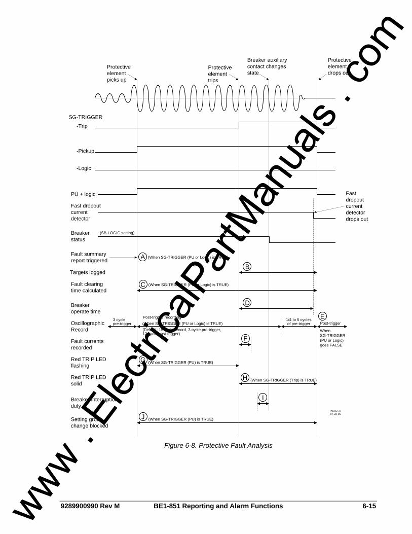
9289900990 Rev M BE1-851 Reporting and Alarm Functions 6-15
Protective element picks up
Protective element trips
Breaker auxiliary contact changes state
Protective element drops out
Fast dropout current detector drops out
SG-TRIGGER
-Pickup
-Logic
PU + logic
Fast dropout current detector
Breaker status
Fault summary report triggered
(When SG-TRIGGER (PU or Logic) is TRUE)AB
Targets logged
CFault clearing time calculated
DBreaker operate time
OscillographicRecord
3 cyclepre-trigger
Post-trigger recording
(Default: 15 cycle record, 3 cycle pre-trigger, 12 cycle post-trigger)
Post-trigger1/4 to 5 cycles of pre-trigger
E
FFault currents recorded
GRed TRIP LED flashing
(When SG-TRIGGER (PU) is TRUE)
HRed TRIP LED solid
Breaker interruption duty
Setting group change blocked
I
JP0032-1707-22-05
(SB-LOGIC setting)
-Trip
WhenSG-TRIGGER (PU or Logic) goes FALSE
(When SG-TRIGGER (PU or Logic) is TRUE)
(When SG-TRIGGER (PU or Logic) is TRUE)
(When SG-TRIGGER (PU) is TRUE)
(When SG-TRIGGER (Trip) is TRUE)
Figure 6-8. Protective Fault Analysis
www . El
ectric
alPar
tMan
uals
. com

6-16 BE1-851 Reporting and Alarm Functions 9289900990 Rev M
Table 6-8. Legend for Figure 6-8
Call-Out Description
A A fault summary report and an oscillographic record are triggered when either the SG-TRIGGER PICKUP or LOGIC expression becomes TRUE.
B
During the time that the SG-TRIGGER TRIP expression is TRUE, targets are logged from each of the protective functions that reach a TRIP state. If a protective function is not being used for tripping purposes, the associated target function can be disabled through the SG-TARG setting.
C Fault clearing time is calculated as the duration of the time that either the SG-TRIGGER PICKUP or LOGIC expression is TRUE.
D Breaker operate time is calculated as the time from when the SG-TRIGGER TRIP expression becomes TRUE until the fast-dropout current detector senses that the breaker has successfully interrupted the current in all poles of the breaker.
E
A second oscillography record is triggered to record the end of the fault if the SG-TRIGGER TRIP expression becomes FALSE. If the SG-TRIGGER TRIP expression does not become TRUE (as would occur if the fault were cleared by a down stream device), the fault current recorded in the fault summary report will be for the power system cycle ending two cycles before the end of the fault record. This is also the case if the fault record was triggered using the RF-TRIG command.
F
The fault currents are recorded in the fault summary report and on the Target Screen of the HMI for the power system cycle immediately following the SG-TRIGGER TRIP expression becoming TRUE. If the SG-TRIGGER TRIP expression does not become TRUE as would occur if the fault were cleared by a down stream device, the fault current recorded in the fault summary report will be for the power system cycle ending two cycles before the end of the fault record. This is also the case if the fault record was triggered through the ASCII command interface by the RF-TRIG command.
G During the time that the SG-TRIGGER PICKUP expression is TRUE, the red Trip LED on the front panel flashes indicating that the relay is picked up.
H During the time the SG-TRIGGER TRIP expression is TRUE, the red Trip LED on the front panel lights steadily indicating that the relay is in a tripped state. If targets have been logged for the fault, the Trip LED is sealed in until the targets have been reset.
I
Breaker operations and interruption duty functions are driven by the breaker status function. The operations counter is incremented on breaker opening. The magnitudes of the currents that are used for accumulating breaker duty are recorded for the power system cycle ending when the breaker status changes state. Breaker duty is accumulated every time that the breaker opens even if it is not opening under fault.
J Setting group changes are blocked when the SG-TRIGGER PICKUP expression is TRUE to prevent protective functions from being reinitialized with new operating parameters while a fault is occurring.
TRIP CIRCUIT MONITOR The trip circuit monitor continually monitors the circuit breaker trip circuit for voltage and continuity. A closed breaker with no voltage detected across the trip contacts can indicate that a trip circuit fuse is open or there is a loss of continuity in the trip coil circuit. Breaker status (open or closed) is obtained through the breaker status reporting function. The detector circuit used by the trip circuit monitor is hardwired across the OUT1 contact. This contact is used in all of the preprogrammed logic schemes as the main trip output. The detector circuit draws less than 1 milliampere of current through the trip coil when the breaker is closed. Figure 6-9 illustrates typical trip circuit monitor connections for the BE1-851. If the breaker status reporting function detects a closed breaker and no trip circuit voltage is sensed by the trip circuit monitor after the appropriate coordination time delay (about 500 milliseconds), an alarm bit in the programmable alarms function is set and the OUT1MON BESTlogic variable is set to TRUE.
www . El
ectric
alPar
tMan
uals
. com
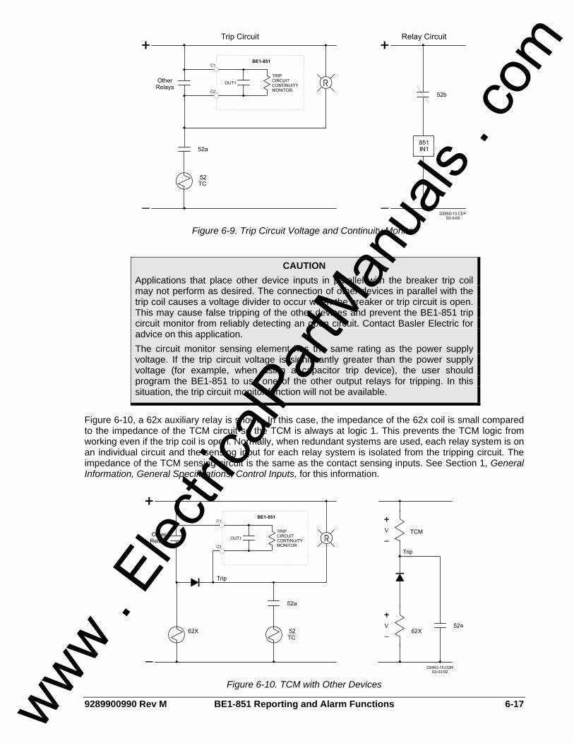
9289900990 Rev M BE1-851 Reporting and Alarm Functions 6-17
Figure 6-9. Trip Circuit Voltage and Continuity Monitor
Figure 6-10, a 62x auxiliary relay is shown. In this case, the impedance of the 62x coil is small compared to the impedance of the TCM circuit so the TCM is always at logic 1. This prevents the TCM logic from working even if the trip coil is open. Normally, when redundant systems are used, each relay system is on an individual circuit and the sensing input for each relay system is isolated from the tripping circuit. The impedance of the TCM sensing circuit is the same as the contact sensing inputs. See Section 1, General Information, General Specifications, Control Inputs, for this information.
Figure 6-10. TCM with Other Devices
CAUTION Applications that place other device inputs in parallel with the breaker trip coil may not perform as desired. The connection of other devices in parallel with the trip coil causes a voltage divider to occur when the breaker or trip circuit is open. This may cause false tripping of the other devices and prevent the BE1-851 trip circuit monitor from reliably detecting an open circuit. Contact Basler Electric for advice on this application. The circuit monitor sensing element has the same rating as the power supply voltage. If the trip circuit voltage is significantly greater than the power supply voltage (for example, when using a capacitor trip device), the user should program the BE1-851 to use one of the other output relays for tripping. In this situation, the trip circuit monitor function will not be available.
www . El
ectric
alPar
tMan
uals
. com

6-18 BE1-851 Reporting and Alarm Functions 9289900990 Rev M
FAULT REPORTING The fault reporting function records and reports information about faults that have been detected by the relay. The BE1-851 provides many fault reporting features. These features include Targets, Fault Summary Reports, Oscillographic Records, and Sequence of Events Recorder Reports.
Logic Expressions for Fault Reporting Logic expressions are used to define the three conditions for fault reporting. These conditions are TRIPPED, PICKED UP, and LOGIC trigger. Figure 6-8 and Table 6-8 illustrate how each of these logic expressions is used by the various relay functions. Note that even though BESTlogic expressions are used to define these conditions, these expressions are not included here. Section 7, BESTlogic Programmable Logic, provides information about using BESTlogic to program the relay.
Tripped TRIPPED expressions are used by the fault reporting function to start logging targets for an event and to record the fault current magnitudes at the time of trip. The HMI used the trip expression to seal-in the Trip LED. The breaker clearing time monitor uses the TRIP expression to begin timing the opening of the circuit breaker. The resulting time is compared to the “Breaker Clearing Time” setting.
Picked Up PICKED UP expressions are used by the fault reporting function to time-stamp the fault summary record, time the length of the fault from pickup to dropout (fault clearing time), and to control the recording of oscillographic data. The HMI uses the pickup expression to control the flashing of the Trip LED. A pickup expression is also used by the setting group selection function to prevent a setting group change during a fault.
Logic LOGIC trigger expressions allow the fault reporting function to be triggered even though the relay is not picked up. A logic trigger expression provides an input to the fault reporting function much as the pickup expression does. This logic expression is not used by the setting group selection or the HMI.
Fault Reporting Trigger Settings Fault reporting trigger settings are made from the BESTlogic Function Element screen in BESTCOMS. Figure 6-11 illustrates the BESTCOMS screen used to select BESTlogic settings for the Fault Recording function. To open the BESTlogic Function Element Screen for Fault Recording, select Reporting and Alarms from the Screens pull-down menu. Select the Fault Recording tab. Then select the Logic button in the upper left hand corner of the screen. Alternately, settings may be made using SG-TRIGGER ASCII command. To connect the function’s inputs, select the button for the corresponding input in the BESTlogic Function Element screen. The BESTlogic Expression Builder screen will open. Select the expression type to be used. Select the BESTlogic variable or series of variables to be connected to the input. Select Save when finished to return to the BESTlogic Function Element screen. For details on the BESTlogic Expression Builder, See Section 7, BESTlogic Programmable Logic. Select Done when the settings have been completely edited. Trigger settings for fault reports are made using the SG-TRIGGER (settings-general, trigger) command.
www . El
ectric
alPar
tMan
uals
. com
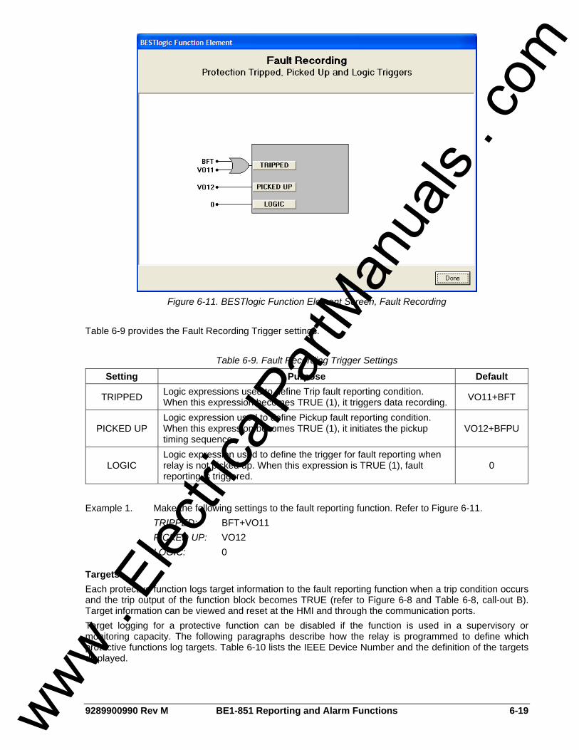
9289900990 Rev M BE1-851 Reporting and Alarm Functions 6-19
Figure 6-11. BESTlogic Function Element Screen, Fault Recording
Table 6-9 provides the Fault Recording Trigger settings.
Table 6-9. Fault Recording Trigger Settings
Setting Purpose Default
TRIPPED Logic expressions used to define Trip fault reporting condition. When this expression becomes TRUE (1), it triggers data recording. VO11+BFT
PICKED UP Logic expression used to define Pickup fault reporting condition. When this expression becomes TRUE (1), it initiates the pickup timing sequence.
VO12+BFPU
LOGIC Logic expression used to define the trigger for fault reporting when relay is not picked up. When this expression is TRUE (1), fault reporting is triggered.
0
Example 1. Make the following settings to the fault reporting function. Refer to Figure 6-11. TRIPPED: BFT+VO11 PICKED UP: VO12 LOGIC: 0
Targets Each protective function logs target information to the fault reporting function when a trip condition occurs and the trip output of the function block becomes TRUE (refer to Figure 6-8 and Table 6-8, call-out B). Target information can be viewed and reset at the HMI and through the communication ports. Target logging for a protective function can be disabled if the function is used in a supervisory or monitoring capacity. The following paragraphs describe how the relay is programmed to define which protective functions log targets. Table 6-10 lists the IEEE Device Number and the definition of the targets displayed.
www . El
ectric
alPar
tMan
uals
. com
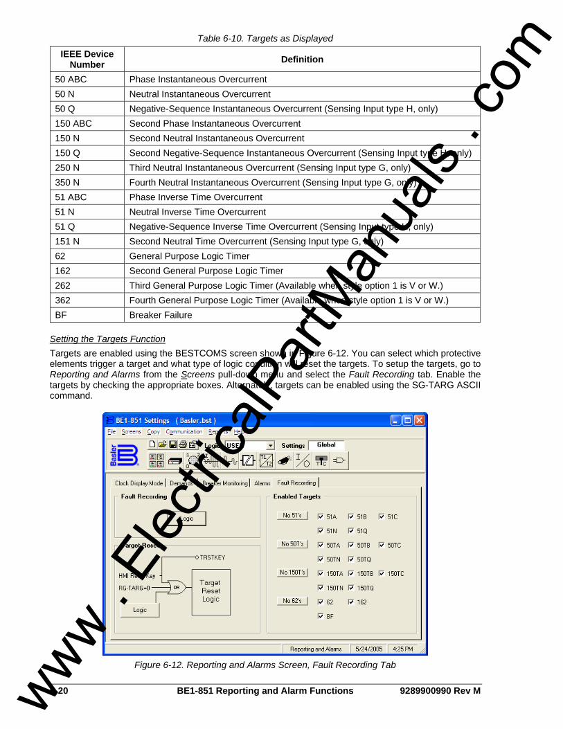
6-20 BE1-851 Reporting and Alarm Functions 9289900990 Rev M
Table 6-10. Targets as Displayed
IEEE Device Number Definition
50 ABC Phase Instantaneous Overcurrent 50 N Neutral Instantaneous Overcurrent 50 Q Negative-Sequence Instantaneous Overcurrent (Sensing Input type H, only) 150 ABC Second Phase Instantaneous Overcurrent 150 N Second Neutral Instantaneous Overcurrent 150 Q Second Negative-Sequence Instantaneous Overcurrent (Sensing Input type H, only) 250 N Third Neutral Instantaneous Overcurrent (Sensing Input type G, only) 350 N Fourth Neutral Instantaneous Overcurrent (Sensing Input type G, only) 51 ABC Phase Inverse Time Overcurrent 51 N Neutral Inverse Time Overcurrent 51 Q Negative-Sequence Inverse Time Overcurrent (Sensing Input type H, only) 151 N Second Neutral Time Overcurrent (Sensing Input type G, only) 62 General Purpose Logic Timer 162 Second General Purpose Logic Timer 262 Third General Purpose Logic Timer (Available when style option 1 is V or W.) 362 Fourth General Purpose Logic Timer (Available when style option 1 is V or W.) BF Breaker Failure
Setting the Targets Function Targets are enabled using the BESTCOMS screen shown in Figure 6-12. You can select which protective elements trigger a target and what type of logic condition will reset the targets. To setup the targets, go to Reporting and Alarms from the Screens pull-down menu and select the Fault Recording tab. Enable the targets by checking the appropriate boxes. Alternately, targets can be enabled using the SG-TARG ASCII command.
Figure 6-12. Reporting and Alarms Screen, Fault Recording Tab
www . El
ectric
alPar
tMan
uals
. com

9289900990 Rev M BE1-851 Reporting and Alarm Functions 6-21
Retrieving Target Information Targets can be viewed at HMI Screen 1.2 and through the communication ports using the RG-TARG (report general, targets) command. The relay provides target information from the most recent trip event. Target information is specific to an event; it is not cumulative. Targets for previous events are recorded in the fault summary reports that are described in the following subsection. When a protective trip occurs and targets are logged, the HMI Trip LED seals-in and Screen 1.2 is automatically displayed. The LCD scrolls between the targets and the fault current magnitudes that were recorded during the fault. Pressing the HMI Reset key will clear these targets and the Trip LED. Password access is not required to reset targets at the HMI. The RG-TARG (report general, targets) command is used to read and reset targets through the communication ports.
Fault Summary Reports The BE1-851 records information about faults and creates fault summary reports. A maximum of 16 fault summary reports are stored in the relay. The two most recent reports are stored in nonvolatile memory. When a new fault summary report is generated, the relay discards the oldest of the 16 fault records and replaces it with a new one. Each fault summary report is assigned a sequential number (from 1 to 255) by the relay. After event number 255 has been assigned, the numbering starts over at 1. Fault reports can be viewed at HMI Screen 4.1.1. To view fault reports using BESTCOMS, select Oscillography Download from the Reports pull-down menu. A screen such as the one shown in Figure 6-13 will appear. From this screen, you can View Fault Details or View Fault Sequence of Events by selecting your choice at the top of the screen and then highlighting the fault to be displayed. In Figure 6-13, fault 002 is highlighted. The Trigger button allows a fault to be manually triggered. This can also be done using the SG-TRIGGER ASCII command. The Refresh button is used to refresh the list of faults. The Download button will download the selected fault, storing it on the selected drive as either a binary or ASCII file, selected beneath the button.
Figure 6-13. View/Download Relay Fault Files Screen
www . El
ectric
alPar
tMan
uals
. com

6-22 BE1-851 Reporting and Alarm Functions 9289900990 Rev M
Fault Summary Report Example A fault summary report collects several items of information about a fault that can aid in determining why a fault occurred without having to sort through all of the detailed information available. The following example illustrates a typical fault summary report. Call-outs shown in the report are references to the legend of Table 6-8.
Example 1. Fault Summary Report.
Style Number. This line reports the style number of the relay. Firmware Version. This line reports the version of firmware that the relay holds. Fault Date and Time. These lines report the date and the time of the initial trigger of the event. This is based on either the pickup logic expression or the logic trigger expression becoming TRUE as defined by the SG-TRIGGER command. Refer to Figure 6-8 and Table 6-8, call-out A. Station ID and Relay ID. These lines report station and device identifier information as defined by the SG-ID command. Relay Address. This line reports the communications port address from which the report was requested. The relay address number is assigned using the SG-COM command, described in Section 11, ASCII Command Interface. Fault Number. This line reports the sequential number (from 1 to 255) assigned to the report by the BE1-851. Fault Trigger. This line reports the logic variables in the pickup or logic trigger expressions that became TRUE to trigger the recording of the event. Event Type. This line reports the type of event that occurred. There are five fault event categories.
• Trip: A fault was detected as defined by the pickup expression and the relay tripped to clear the fault.
• Pickup: A fault was detected as defined by the pickup expression but the relay never tripped indicating that the fault was cleared by another device.
• Logic: A fault report was recorded by the logic trigger expression but no fault was detected as defined by the pickup expression.
• Breaker Failure: A fault was detected as defined by the pickup expression and the breaker failure trip became TRUE before the fault was cleared.
• RF=TRIG: A fault report was recorded by the ASCII command interface.
www . El
ectric
alPar
tMan
uals
. com

9289900990 Rev M BE1-851 Reporting and Alarm Functions 6-23
Active Group. This line reports what setting group was active at the time that the fault occurred. Targets. This line reports the targets that were logged to the fault report between the time that the trip expression became TRUE until the end of the fault. Refer to Figure 6-8 and Table 6-8, call-out B. Recloser State. This line reports the state of the recloser shot counter before the fault that triggered the report. Fault Clearing Time. This line reports the time from when the relay detected the fault until the relay detected that the fault had cleared. Refer to Figure 6-8 and Table 6-8, call-out C. If the fault report was triggered manually from the View/Download Relay Fault Files screen, the recording of the report was terminated after 60 seconds and this line is reported as N/A. If the pickup or logic expressions stay TRUE for more than 60 seconds, an alarm bit in the programmable alarm function is set and this line is reported as N/A. In this situation, the fault reporting functions (including targets) will not operate again until the pickup and logic trigger expressions return to a FALSE state to enable another trigger. Breaker Operate Time. This line reports the breaker trip time from the breaker monitoring and alarm function. This is the time measured from when the breaker is tripped until the fast-dropout current detector function detects that the arc has been extinguished. Refer to Figure 6-8 and Table 6-8, cal-out D. Oscillographic Reports. This line reports the number of oscillographic records (1 or 2) that are stored in memory for this fault report. Refer to Figure 6-8 and Table 6-8, call-out E. Recording of oscillographic records is described in the Oscillographic Records subsection. IA, IB, IC, IN, IQ. These lines report the current magnitudes measured two power system cycles immediately following the trigger trip. If the fault is cleared before the relay tripping, the recorded fault currents are for the power system cycle two cycles before the end of the fault. If the relay has been set to the average current measurement algorithm, these currents may not be representative due to the time constant inherent in the measurement algorithm. Refer to Figure 6-8 and Table 6-8, call-out F.
Retrieving Fault Report Information from the Relay Fault Summary Directory Report. The fault reporting function provides a directory of fault summary reports that lists the number assigned to the fault summary report along with the date and time of the fault, the event type, and the total number of oscillography records stored in memory for that event. The event number is important because it is required to retrieve information about that event from the relay. This directory report can be accessed by using the RF command.
New Faults Counter. One line of the fault summary directory report contains the new faults counter. The new faults counter tracks how many new fault reports have been recorded since the new faults counter was reset to 0. This counter provides a way to check the fault information and then reset the new faults counter. Then, the next time that the relay is checked, it is easy to determine if any fault reports have been entered. Resetting the new faults counter is achieved using the RF-NEW=0 command. Write access to Reports must be gained to reset the new faults counter through the communication ports. The new faults counter can also be viewed and reset at HMI Screen 4.1. Fault Summary Reports. Individual fault summary reports can be retrieved using the RF-n command where n represents the number assigned to the fault summary report. To obtain the most recent report, use the command RF-NEW. If additional detail is desired, Sequence of Events Recorder data and oscillographic data can also be obtained for the faults. This is discussed in detail later in this section.
Receiving Fault Report Information from COM1 using the SG-DATADUMP command When the DATADUMP function is enabled, a fault summary report is automatically sent to COM1 (Rear RS-232) each time a fault occurs. For more information on fault summary reports, see Fault Summary Reports, explained previously in this section.
Refer to Section 14, BESTCOMS Software, Setting the Relay, General Operation, Communication for information on enabling the DATADUMP through BESTCOMS.
NOTE If ACCESS is held on COM1 (Rear RS-232), the DATADUMP function will be paused until ACCESS is released by using the “EXIT” command.
www . El
ectric
alPar
tMan
uals
. com

6-24 BE1-851 Reporting and Alarm Functions 9289900990 Rev M
Oscillographic Records The fault reporting function can record up to 16 IEEE Standard Common Format for Transient Data Exchange (COMTRADE) oscillographic records. Each record is 15 cycles long and records 24 samples per cycle for the A, B, C, and N current inputs. The relay uses 24 samples per cycle in its operation. Each time the fault reporting function starts recording a fault summary report, it freezes a 3-cycle pre-fault buffer and records for 12 post-trigger cycles. If the fault is not cleared within that time, the fault reporting function records a second oscillographic record. If a second oscillographic record is required, the fault recording function will continue to record sample data in the second record with no gap. During this time, a 5-cycle buffer is being filled. If the fault is cleared within 5 cycles of the start of the second record, the record is terminated after it has recorded 15 cycles. IF the fault does not clear in that period, the fault reporting function continues to save 5 cycles of sample data in its buffer until the fault is cleared. At that point, it freezes the 5-cycle buffer, providing 5 cycles of end of fault data and 10 cycles of post-fault data. An oscillographic record is triggered when the PICKED Up or LOGIC Expressions defined by the FAULT RECORDING logic becomes TRUE. The oscillographic record will contain 3 cycles of pre-trigger data and 8 cycles of post-trigger data. Twelve samples will be stored every cycle. Each sample will contain 16-bit A/D values for all four analog channels (IA, IB, IC, and IN) and a 1 or 0 for each of the 64 digital channels. The digital channels are updated every ¼ cycle, but they are recorded every 1/24 cycle. If the fault is not cleared by the end of the record, then a second oscillographic report will be triggered as soon as the first ends. The first report will cover the initiation of the fault (start fault) and the second report will cover the breaker operate time (end fault). Oscillographic records are stored in volatile memory. As additional faults are recorded, the oldest records are overwritten.
Table 6-11. Oscillographic Hardware Support
Feature Version 2.xx Version 3.xx Version 4.xx Number of Oscillographic Records 12 16 16
Length of Oscillographic Records 11 cycles each 15 cycles each 15 cycles each
Sample Resolution 24 samples per cycle 24 samples per cycle 24 samples per cycle
Retrieving Oscillographic Records The fault summary directory and the fault summary reports list the numbers assigned to each fault record and the number of oscillographic records associated with each fault. Oscillographic records can be retrieved using BESTCOMS. Alternately, oscillographic records can be retrieved using the RO ASCII command. To download oscillographic records, select Oscillography Download from the Reports pull-down menu. Highlight the record that you would like to downloaded and select either ASCII or binary as the file type for download. Select the Download button. In Figure 6-14, record 019 is selected for a binary download. When the Download button is selected, the Browse for Folder screen appears. See Figure 6-15. Select a location for the file to be stored, or create a New Folder and press OK. The Fault Record Filename screen will appear. Type the base filename in the first row, the rest of the filenames will respond by changing to match the base filename. Select OK to save the file.
www . El
ectric
alPar
tMan
uals
. com
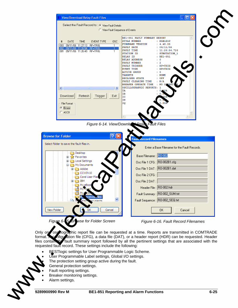
9289900990 Rev M BE1-851 Reporting and Alarm Functions 6-25
Figure 6-14. View/Download Relay Fault Files
Figure 6-15. Browse for Folder Screen
Figure 6-16. Fault Record Filenames
Only one oscillographic report file can be requested at a time. Reports are transmitted in COMTRADE format. A configuration file (CFG), a data file (DAT), or a header report (HDR) can be requested. Header files contain the fault summary report followed by all the pertinent settings that are associated with the requested fault record. These settings include the following:
• BESTlogic settings for User Programmable Logic Scheme. • User Programmable Label settings, Global I/O settings. • The protection setting group active during the fault. • General protection settings. • Fault reporting settings. • Breaker monitoring settings. • Alarm settings.
www . El
ectric
alPar
tMan
uals
. com
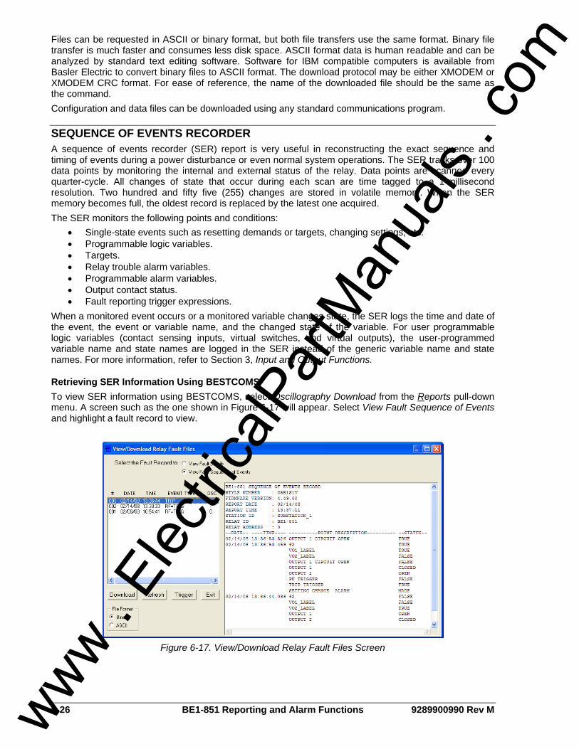
6-26 BE1-851 Reporting and Alarm Functions 9289900990 Rev M
Files can be requested in ASCII or binary format, but both file transfers use the same format. Binary file transfer is much faster and consumes less disk space. ASCII format data is human readable and can be analyzed by standard text editing software. Software for IBM compatible computers is available from Basler Electric to convert binary files to ASCII format. The download protocol may be either XMODEM or XMODEM CRC format. For ease of reference, the name of the downloaded file should be the same as the command. Configuration and data files can be downloaded using any standard communications program.
SEQUENCE OF EVENTS RECORDER A sequence of events recorder (SER) report is very useful in reconstructing the exact sequence and timing of events during a power disturbance or even normal system operations. The SER tracks over 100 data points by monitoring the internal and external status of the relay. Data points are scanned every quarter-cycle. All changes of state that occur during each scan are time tagged to a 1-millisecond resolution. Two hundred and fifty five (255) changes are stored in volatile memory. When the SER memory becomes full, the oldest record is replaced by the latest one acquired. The SER monitors the following points and conditions:
• Single-state events such as resetting demands or targets, changing settings, etc. • Programmable logic variables. • Targets. • Relay trouble alarm variables. • Programmable alarm variables. • Output contact status. • Fault reporting trigger expressions.
When a monitored event occurs or a monitored variable changes state, the SER logs the time and date of the event, the event or variable name, and the changed state of the variable. For user programmable logic variables (contact sensing inputs, virtual switches, and virtual outputs), the user-programmed variable name and state names are logged in the SER instead of the generic variable name and state names. For more information, refer to Section 3, Input and Output Functions.
Retrieving SER Information Using BESTCOMS To view SER information using BESTCOMS, select Oscillography Download from the Reports pull-down menu. A screen such as the one shown in Figure 6-17 will appear. Select View Fault Sequence of Events and highlight a fault record to view.
Figure 6-17. View/Download Relay Fault Files Screen
www . El
ectric
alPar
tMan
uals
. com

9289900990 Rev M BE1-851 Reporting and Alarm Functions 6-27
Retrieving SER Information Using ASCII Commands SER information is retrieved through SER Directory Reports, the New Events Counter, and by obtaining specific SER Reports. SER Directory Report. A directory report lists the number of events currently in memory and the time span that the events cover. Directory reports are accessed using the RS (report SER) command. New Events Counter. The new events counter tracks how many new entries have been logged to the SER since the new events counter was reset to zero. After SER information is checked, the new events counter can be reset. Then, the next time that the relay is checked, it is easy to determine if there are new events that have not been evaluated. One line of an SER directory report contains the new events counter information. The new events counter is reset by obtaining write access to Reports and using the RS=0 command. The new events counter can be viewed but not reset at HMI Screen 4.2. SER. A directory of SERs can be obtained using the RS (report SER) command. Six sub-reports are available through the RS command: RS-n, RS-Fn, RS-ALM, RS-I/O, RS-LGC, and RS-NEW. These sub-reports give specific types of data without confusing the user with every internal state change and event occurrence. Each sub-report is defined in the following paragraphs. RS-n (report SER, number of most recent events). Events are retrieved for the most recent entries. Entering RS-4 would view an SER for the last four events. RS-F<n> (report SER, for Fault <event number>). Events are retrieved for the period specific to a fault event. The report includes all events within the time span of the fault plus one event before and after the fault. Entering RS-F9 will show an SER associated with fault record 9. RS-ALM (report SER, alarm). This command retrieves all alarm events that exist since the last RS=0 command was issued. (RS=0 resets the new records counter to zero.) This information can also be obtained using the RA-SER command. RS-I/O (report SER, input/output). This command reports all input and output events since the last RS=0 command was issued. (RS=0 resets the New Records counter to 0.) RS-LGC (report SER, logic). A report is retrieved for all logic events since the last RS=0 command was issued. (RS=0 resets the New Records counter to zero.) RS-NEW (report SER, new events since RS=0 reset). Events are retrieved for the period of time covered by the New Events Counter register.
ALARMS FUNCTION The “alarms function” monitors internal relay systems, external relay interfaces, and power system equipment. Alarm points are segregated into Relay Trouble Alarms and Programmable Alarms. Alarm point status is stored in nonvolatile memory and is retained when relay operating power is lost. The ability to program the reporting and display of alarms along with the automatic display priority feature of the HMI gives the relay the functionality to annunciate local and remote alarms. See Section 10, Human-Machine Interface, for more information on the automatic display priority logic.
Relay Trouble Alarms All internal circuitry and software that affects how the relay functions is monitored by the continuous self-test diagnostics function of the relay trouble alarms. A detailed list of relay trouble alarms is provided in Table 6-12. If any one of these points asserts, the fail-safe alarm output relay de-energizes allowing the OUTA contact to close or open depending on the style number, the HMI Relay Trouble LED to light, all output relays to become disabled, and the relay to be taken offline. The relay trouble alarms function is not programmable. If power is lost to the relay, the OUTA contact will close or open depending on the style number. If your application requires a normally closed contact that opens to indicate a relay trouble condition, use BESTlogic to program the output logic. One of the output relays with normally open contacts (OUT1 through OUT5) can be programmed so that it is held closed. For example, to open OUT5 for indication of relay trouble, set the VO5 logic expression at /0 (SL-VO5=/0). A “not zero” setting is equal to logic 1. When the relay is fully functional, the OUT5 output contact is closed. Since all output relays are disabled when a relay trouble alarm exists, OUT5 opens when relay trouble occurs. www .
Elec
tricalP
artM
anua
ls . c
om

6-28 BE1-851 Reporting and Alarm Functions 9289900990 Rev M
Table 6-12. Relay Trouble Alarms
I.D. # Name Description 1 RAM FAILURE Static RAM read/write error. 2 ROM FAILURE EPROM program memory checksum error. 3 UP FAILURE Microprocessor exception or self-test error. 4 EEPROM FATAL ERROR EEPROM read/write error. 5 ANALOG FAILURE Analog to digital converter error. 6 CALIBRATION ERR Relay not calibrated or calibration checksum error. 7 PWR SUPPLY ERR Power supply out of tolerance. 8 WATCHDOG FAILURE Microprocessor watchdog circuit timed out. 9 SET DEFLTS LOADED Relay using setting defaults.
10 CAL DFLTS LOADED Relay using calibration defaults.
Relay trouble alarms, except for CALIBRATION ERR, EEPROM FATAL ERR, SET DFLTS LOADED, and CAL DFLTS LOADED indicate that the relay is not functional and causes the self-test diagnostics to force a microprocessor reset to try to correct the problem. CALIBRATION ERR, EEPROM FATAL ERROR, or DFLTS LOADED errors indicate that the relay is functional but needs re-calibration or the setting re-programmed. Any relay trouble alarm will disable the protection functions, light the Relay Trouble LED, and place the output contacts in their normal, de-energized state. If a relay trouble (RA-REL) alarm is cleared by pressing the HMI Reset key while viewing Screen 1.3 or using the RA=0 or RA-REL=0 commands, then the relay will attempt to return back online by issuing a software reset. The relay resets by going through a full startup and initialization cycle. If no problems are detected, the relay returns online and enables protection.
Major, Minor, and Logic Programmable Alarms The programmable alarms function covers all circuits monitored by the continuous self-test diagnostics function that does not affect the relay core functions. The alarm function used to monitor the power system and equipment is part of the programmable alarms. Table 6-13 provides a detailed list of all programmable alarms. The programmable alarm points can be prioritized into Major and Minor alarms using the SA-MAJ (setting alarms, major) and SA-MIN (setting alarms, minor) commands. Major alarm points, when triggered, cause the HMI Major Alarm LED to light and the BESTlogic variable ALMMAJ to assert. Minor alarm points, when triggered, cause the HMI Minor Alarm LED to light and the BESTlogic variable ALMMIN to assert.
Table 6-13. Programmable Alarms
I.D. # Name Description
1 OUT1 CKT OPEN ALARM ∗ Trip circuit continuity and voltage monitor.
2 BKR FAIL ALARM Breaker failure trip.
3 RECLOSER FAIL ALARM ∗ Reclose fail timer timed out before breaker closed.
4 RECLOSER LOCKOUT ALARM ∗ Recloser went through sequence without success.
5 BREAKER ALARM 1 Breaker Alarm 1 threshold (SA-BKR1 setting) exceeded.
6 BREAKER ALARM 2 Breaker Alarm 2 threshold (SA-BKR1 setting) exceeded.
7 BREAKER ALARM 3 Breaker Alarm 3 threshold (SA-BKR1 setting) exceeded.
8 P DEMAND ALARM ∗ Phase demand.
9 N DEMAND ALARM ∗ Neutral unbalance demand.
www . El
ectric
alPar
tMan
uals
. com

9289900990 Rev M BE1-851 Reporting and Alarm Functions 6-29
I.D. # Name Description
10 Q DEMAND ALARM ∗ Negative-sequence unbalance demand.
11 GROUP OVERRIDE ALARM ∗ Setting group control logic override.
12 SYS I/O DELAY ALARM Excessive delay in HMI or serial communication operation.
13 COMM ERROR ALARM Communication failure.
14 CLOCK ERROR ∗ Real-time clock not set.
15 uP RESET ALARM Microprocessor has been reset.
16 SETTING CHANGE ALARM Setting change made by user.
17 EE NONFATAL ERR ALARM EEPROM nonfatal recoverable error.
18 OUTPUT OVERRIDE ALARM ∗ One or more output contacts have logic override condition.
19 IRIG SYNC LOST ALARM Loss of IRIG synchronization.
20 SGC ACTIVE ALARM ∗ Active setting group changed.
21 VO13 LOGIC ALRM ∗ VO13 logic is TRUE (user programmable logic alarm).
22 VO14 LOGIC ALRM ∗ VO14 logic is TRUE (user programmable logic alarm).
23 VO15 LOGIC ALRM ∗ VO15 logic is TRUE (user programmable logic alarm).
24 FLT RPT TIMEOUT ALARM TRUE if fault event trigger lasts longer than 60 seconds.
25 LOGIC=NONE ALARM Active Logic=NONE.
26 CHANGES LOST ALARM Changes made on serial port not saved after 5 minutes.
∗ Alarms with an asterisk (∗) are non-latching. A non-latching alarm clears itself automatically when the alarm condition goes away. All other alarms are latching and must be manually reset by using the HMI Reset button or the RA=0 command. The output of any programmable alarm can also be used in programmable logic expressions without being programmed to be reported by the programmable alarm reporting function. The ALMLGC variable is provided for this purpose. Programmable alarm variables can be masked to drive BESTlogic variable ALMLGC by using the SA-LGC command.
Programming Alarm Priorities Alarm setting include Major, Minor, and Logic alarm priorities, Demand alarm points, and the Breaker alarm points. Programming details for Demand alarm points are available in the Demand Functions subsection. Refer to the Breaker Monitoring subsection for details about programming Breaker alarm points. Major, Minor, and Logic programmable alarm settings are made using BESTCOMS. To select alarm priority, select Reporting and Alarms from the Reports pull-down menu. Select the Alarms tab (see Figure 6-18). Set the alarm point priority by checking the box or boxes to its right. Table 6-14 summarizes major, minor, and logic programmable alarm settings.
www . El
ectric
alPar
tMan
uals
. com
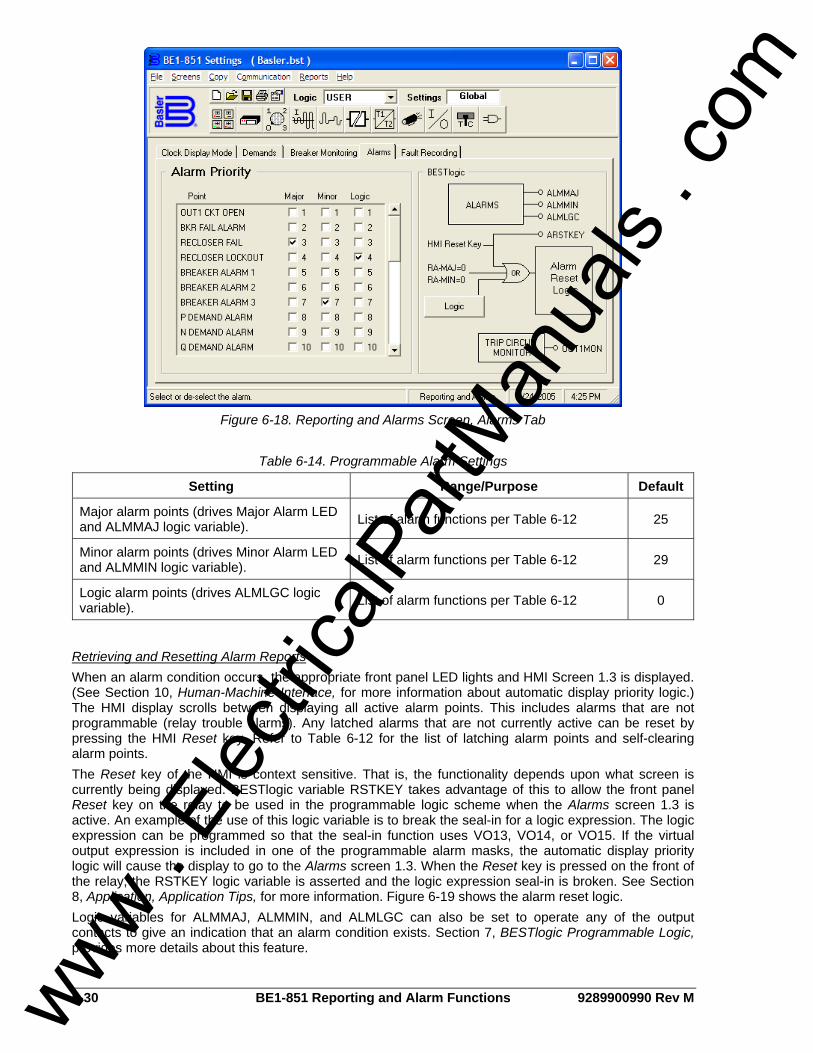
6-30 BE1-851 Reporting and Alarm Functions 9289900990 Rev M
Figure 6-18. Reporting and Alarms Screen, Alarms Tab
Table 6-14. Programmable Alarm Settings
Setting Range/Purpose Default
Major alarm points (drives Major Alarm LED and ALMMAJ logic variable). List of alarm functions per Table 6-12 25
Minor alarm points (drives Minor Alarm LED and ALMMIN logic variable). List of alarm functions per Table 6-12 29
Logic alarm points (drives ALMLGC logic variable). List of alarm functions per Table 6-12 0
Retrieving and Resetting Alarm Reports When an alarm condition occurs, the appropriate front panel LED lights and HMI Screen 1.3 is displayed. (See Section 10, Human-Machine Interface, for more information about automatic display priority logic.) The HMI display scrolls between displaying all active alarm points. This includes alarms that are not programmable (relay trouble alarms). Any latched alarms that are not currently active can be reset by pressing the HMI Reset key. Refer to Table 6-12 for the list of latching alarm points and self-clearing alarm points. The Reset key of the HMI is context sensitive. That is, the functionality depends upon what screen is currently being displayed. BESTlogic variable RSTKEY takes advantage of this to allow the front panel Reset key on the relay to be used in the programmable logic scheme when the Alarms screen 1.3 is active. An example of the use of this logic variable is to break the seal-in for a logic expression. The logic expression can be programmed so that the seal-in function uses VO13, VO14, or VO15. If the virtual output expression is included in one of the programmable alarm masks, the automatic display priority logic will cause the display to go to the Alarms screen 1.3. When the Reset key is pressed on the front of the relay, the RSTKEY logic variable is asserted and the logic expression seal-in is broken. See Section 8, Application, Application Tips, for more information. Figure 6-19 shows the alarm reset logic. Logic variables for ALMMAJ, ALMMIN, and ALMLGC can also be set to operate any of the output contacts to give an indication that an alarm condition exists. Section 7, BESTlogic Programmable Logic, provides more details about this feature.
www . El
ectric
alPar
tMan
uals
. com

9289900990 Rev M BE1-851 Reporting and Alarm Functions 6-31
D2863-16.vsd12-06-99
RA-MAJ=0
Logic
AlarmResetLogic
RA-MIN=0
RSTKEY
HMI RESET KEY
Figure 6-19. Programmable Alarm Function
The status of the three front-panel LEDs (Relay Trouble, Minor Alarm, and Major Alarm) can be read through the communication ports by using the RG-STAT command. Alarm status is given in the DIAG/ALARM line of the General Status Report. Refer to the General Status Reporting subsection for more information about obtaining relay status with the RG-STAT command. The RA (report alarms) command can be used to read detailed alarm reports and reset latched alarms.
Links between Programmable Alarms and BESTlogic Several links between the programmable alarms and BESTlogic allow alarm functions to be used in the logic scheme and programmable logic functions to be used in the alarm reporting function.
Programmable Alarms Controlled by BESTlogic Elements Virtual outputs VO13, VO14, and VO15 are driven by BESTlogic expressions and are available in the programmable alarms function. These three virtual outputs have labels that can be assigned meaningful names. When a logic condition that is used for an alarm exists, the label will be reported in the alarm reporting function.
Programmable Alarms Reset Programmable alarms can be reset by any one of three methods:
• The programmable alarms reset logic expression becomes TRUE. • Pressing the front panel Reset key when HMI Screen 1.3 is active. • By connecting the alarms reset logic in BESTCOMS. Alternately, this can be done using the SA-
RESET ASCII command.
To reset the alarms using BESTCOMS, select Reporting and Alarms from the Screens pull-down menu. Then select the Alarms tab. Select the Logic button in the BESTlogic box on the right side of the screen. Refer to Figure 6-18. The BESTlogic Function Element screen for Alarm Reset Logic will appear. See Figure 6-20. To connect the function’s input, select the RESET button in the BESTlogic Function Element screen. The BESTlogic Expression Builder screen will open. Select the expression type to be used. Then, select the BESTlogic variable or series of variables to be connected to the input. Select Save when finished to return to the BESTlogic Function Element screen. For more details on the BESTlogic Expression Builder, see Section 7, BESTlogic Programmable Logic. Select Done when the settings have been completely edited. In the example of Figure 6-20, the programmable alarms will be reset when either IN3 or IN4 becomes TRUE.
www . El
ectric
alPar
tMan
uals
. com
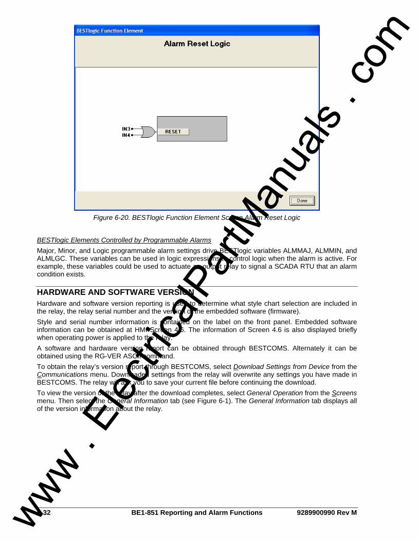
6-32 BE1-851 Reporting and Alarm Functions 9289900990 Rev M
Figure 6-20. BESTlogic Function Element Screen Alarm Reset Logic
BESTlogic Elements Controlled by Programmable Alarms Major, Minor, and Logic programmable alarm settings drive BESTlogic variables ALMMAJ, ALMMIN, and ALMLGC. These variables can be used in logic expressions to control logic when the alarm is active. For example, these variables could be used to actuate an output relay to signal a SCADA RTU that an alarm condition exists.
HARDWARE AND SOFTWARE VERSION Hardware and software version reporting is used to determine what style chart selection are included in the relay, the relay serial number and the version of the embedded software (firmware). Style and serial number information is contained on the label on the front panel. Embedded software information can be obtained at HMI Screen 4.6. The information of Screen 4.6 is also displayed briefly when operating power is applied to the relay. A software and hardware version report can be obtained through BESTCOMS. Alternately it can be obtained using the RG-VER ASCII command. To obtain the relay’s version report through BESTCOMS, select Download Settings from Device from the Communications menu. Downloaded settings from the relay will overwrite any settings you have made in BESTCOMS. The relay will ask you to save your current file before continuing the download. To view the version of the relay after the download completes, select General Operation from the Screens menu. Then select the General Information tab (see Figure 6-1). The General Information tab displays all of the version information about the relay.
www . El
ectric
alPar
tMan
uals
. com
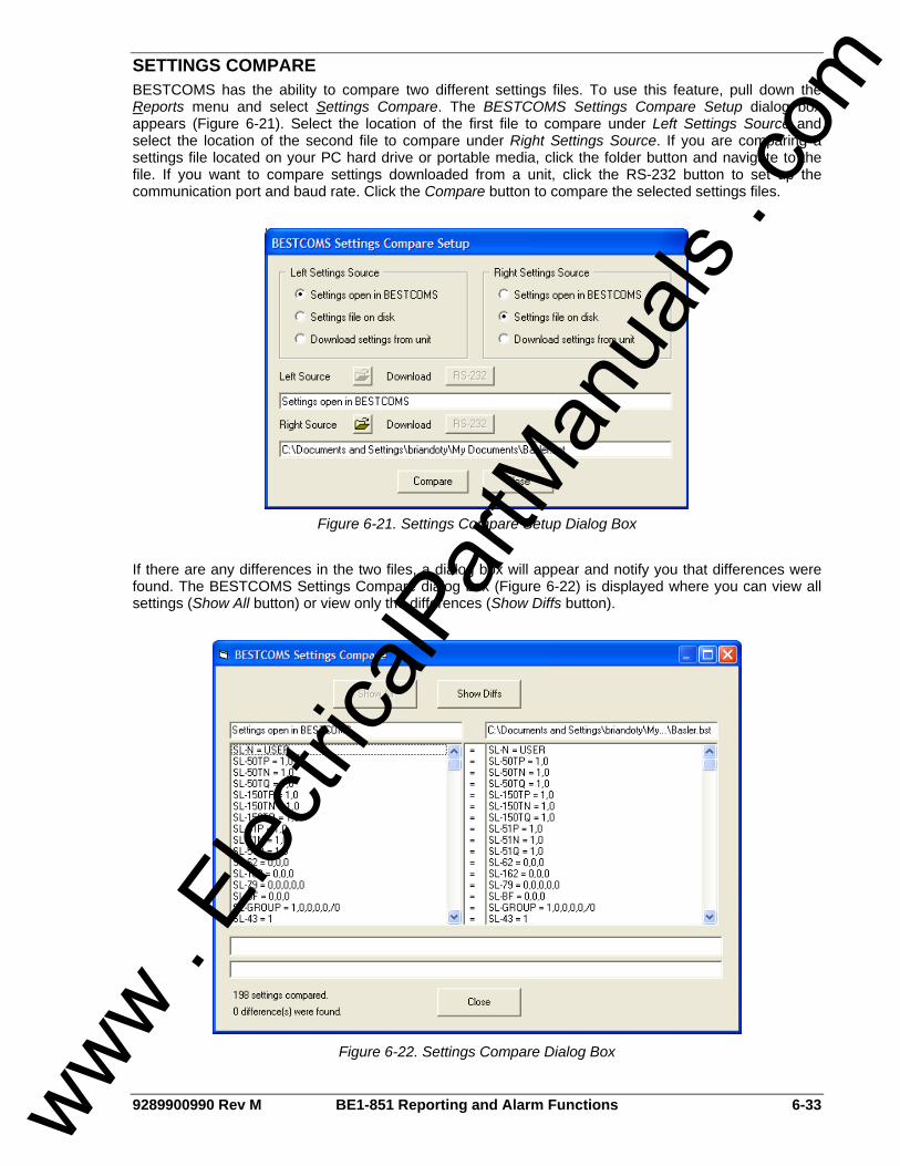
9289900990 Rev M BE1-851 Reporting and Alarm Functions 6-33
SETTINGS COMPARE BESTCOMS has the ability to compare two different settings files. To use this feature, pull down the Reports menu and select Settings Compare. The BESTCOMS Settings Compare Setup dialog box appears (Figure 6-21). Select the location of the first file to compare under Left Settings Source and select the location of the second file to compare under Right Settings Source. If you are comparing a settings file located on your PC hard drive or portable media, click the folder button and navigate to the file. If you want to compare settings downloaded from a unit, click the RS-232 button to set up the communication port and baud rate. Click the Compare button to compare the selected settings files.
Figure 6-21. Settings Compare Setup Dialog Box
If there are any differences in the two files, a dialog box will appear and notify you that differences were found. The BESTCOMS Settings Compare dialog box (Figure 6-22) is displayed where you can view all settings (Show All button) or view only the differences (Show Diffs button).
Figure 6-22. Settings Compare Dialog Box
www . El
ectric
alPar
tMan
uals
. com

6-34 BE1-851 Reporting and Alarm Functions 9289900990 Rev M
This page intentionally left blank.
www . El
ectric
alPar
tMan
uals
. com
9289900990 Rev M BE1-851 BESTlogic Programmable Logic i
SECTION 7 • BESTLOGIC PROGRAMMABLE LOGIC
TABLE OF CONTENTS SECTION 7 • BESTLOGIC PROGRAMMABLE LOGIC ........................................................................... 7-1
INTRODUCTION.................................................................................................................................... 7-1 WORKING WITH PROGRAMMABLE LOGIC ....................................................................................... 7-1
Function Block Logic Settings ............................................................................................................ 7-6 Output Logic Settings ......................................................................................................................... 7-6
LOGIC SCHEMES ................................................................................................................................. 7-8 User Logic Scheme ............................................................................................................................ 7-9 Custom Logic Schemes ................................................................................................................... 7-10 Creating or Customizing a Logic Scheme........................................................................................ 7-10 Sending and Retrieving Relay Settings............................................................................................ 7-10 Debugging the Logic Scheme .......................................................................................................... 7-11
USER INPUT AND OUTPUT LOGIC VARIABLE NAMES.................................................................. 7-11 BESTLOGIC APPLICATION TIPS....................................................................................................... 7-12
Figures Figure 7-1. BESTlogic Sensing Input Type G Function Blocks................................................................. 7-2 Figure 7-2. BESTlogic Sensing Input Type H Function Blocks ................................................................. 7-3 Figure 7-3. 79 Reclosing Logic Function Block ......................................................................................... 7-6 Figure 7-4. Virtual Output Logic................................................................................................................. 7-7 Figure 7-5. BESTlogic Expression Builder Screen.................................................................................... 7-8 Figure 7-6. BESTlogic Screen, Logic Select Tab. ..................................................................................... 7-9
Tables Table 7-1. Logic Variable Names and Descriptions for Sensing Input Type H Relays ............................. 7-4 Table 7-2. Logic Variable Names and Descriptions for Sensing Input Type G Relays............................. 7-5 Table 7-3. Label Settings for INPUTS ..................................................................................................... 7-11 Table 7-4. Label Settings for OUTPUTS ................................................................................................. 7-11 Table 7-5. Label Settings for 43 SWITCHES .......................................................................................... 7-11
www . El
ectric
alPar
tMan
uals
. com

ii BE1-851 BESTlogic Programmable Logic 9289900990 Rev M
This page intentionally left blank.
www . El
ectric
alPar
tMan
uals
. com
9289900990 Rev M BE1-851 BESTlogic Programmable Logic 7-1
SECTION 7 • BESTLOGIC PROGRAMMABLE LOGIC
INTRODUCTION Multifunction relays are similar in nature to a panel of single-function protective relays. Both must be wired together with ancillary devices to operate as a complete protection and control system. In the single-function static and electromechanical environment, elementary diagrams, and wiring diagrams provide direction for wiring protective elements, switches, meters, and indicator lights into a unique protection and control system. In the digital, multifunctional environment, the process of wiring individual protection or control elements is replaced with the entry of logic settings. The process of creating a logic scheme is the digital equivalent of wiring a panel. It integrates the multifunction protection, control, and input/output elements into a unique protection and control system. BESTlogic is a programming method used for managing the input, output, protection, control, monitoring, and reporting capabilities of Basler Electric’s digital, multifunction, protective relay systems. Each relay system has multiple, self-contained function blocks that have all of the inputs and outputs of its discrete component counterpart. Each independent function block interacts with control inputs, virtual outputs, and hardware outputs based on logic variables defined in equation form with BESTlogic. BESTlogic equations entered and saved in the relay system’s nonvolatile memory integrate (electronically wire) the selected or enabled protection and control blocks with control inputs, virtual outputs, and hardware outputs. A group of logic equations defining the function of the multifunction relay is called a logic scheme. Several preprogrammed logic schemes are stored in relay memory. Each scheme is configured for a typical protection application and virtually eliminates the need for start-from-scratch programming. Any of the preprogrammed schemes can be copied and saved as the active logic. Preprogrammed logic schemes can also be copied and then customized to suit your application. Detailed information about preprogrammed logic schemes is provided later in this section. BESTlogic is not used to define the operating settings (pickup thresholds and time delays) of the individual protection and control functions. Operating settings and logic settings are interdependent but separately programmed functions. Changing logic settings is similar to rewiring a panel, and is separate and distinct from making the operating settings that control the pickup thresholds and time delays of a relay. Detailed information about operating settings is provided in Section 4, Protection and Control.
WORKING WITH PROGRAMMABLE LOGIC BESTlogic uses two types of logic settings: output logic settings and function block logic settings. These two types of settings are discussed in the following subsections. Output logic settings are entered in equation form and control the hardware outputs of the relay. BESTlogic function blocks are illustrated in Figures 7-1 and 7-2. These are discussed in the following paragraphs. Names assigned to inputs, outputs, timers, and protection and control elements represent the logic variables in the equations. Tables 7-1 and 7-2 list the logic variable names and descriptions.
www . El
ectric
alPar
tMan
uals
. com

7-2 BE1-851 BESTlogic Programmable Logic 9289900990 Rev M
Figure 7-1. BESTlogic Sensing Input Type G Function Blocks
www . El
ectric
alPar
tMan
uals
. com

9289900990 Rev M BE1-851 BESTlogic Programmable Logic 7-3
Figure 7-2. BESTlogic Sensing Input Type H Function Blocks
www . El
ectric
alPar
tMan
uals
. com

7-4 BE1-851 BESTlogic Programmable Logic 9289900990 Rev M
Table 7-1. Logic Variable Names and Descriptions for Sensing Input Type H Relays
Variable Name Description Variable
Name Description
Inputs and Outputs Time Overcurrent IN1 – IN4 Inputs 1 through 4 Status 51PT 51 Phase Tripped
VOA Relay Trouble Alarm Output Status 51PPU 51 Phase Picked Up
VO1 – VO5 Virtual Outputs 1 through 5 (hardware outputs) 51NT 51 Neutral Tripped
VO6 – VO15 Virtual Outputs 6 through 15 51NPU 51 Neutral Picked Up
Controls 51QT 51 Negative-Sequence Tripped
RSTKEY HMI Target Reset Key 51QPU 51 Negative-Sequence Picked Up
101T Virtual Breaker Control Switch Tripped Instantaneous Overcurrent 101C Virtual Breaker Control Switch Closed 50TPT 50T Phase Tripped
101SC Virtual Breaker Control Switch Slip Contact 50TPPU 50T Phase Picked Up
62 62 Timer Output 50TNT 50T Neutral Tripped
162 162 Timer Output 50TNPU 50T Neutral Picked Up
43 Virtual Switch 43 Output 50TQT 50T Negative-Sequence Tripped
143 Virtual Switch 143 Output 50TQPU 50T Negative-Sequence Picked Up
243 Virtual Switch 243 Output 150TPT 150T Phase Tripped
343 Virtual Switch 343 Output 150TPPU 150T Phase Picked Up
SG0 Setting Group 0 Active (default) 150TNT 150T Neutral Tripped
SG1 Setting Group 1 Active 150TNPU 150T Neutral Picked Up
SG2 Setting Group 2 Active 150TQT 150T Negative-Sequence Tripped
SG3 Setting Group 3 Active 150TQPU 150T Negative-Sequence Picked Up
Alarms and Monitor ALMLGC Logic Alarm
ALMMAJ Major Alarm
ALMMIN Minor Alarm
OUT1MON Output 1 Monitor (circuit continuity)
Reclosing 79C 79 Close Signal
79RNG 79 Running/Block Tap Changer
79LO 79 Lockout
79F 79 Reclose Fail
79SCB 79 Sequence Control Block
Breaker Failure BFT Breaker Failure Tripped
BFPU Breaker Failure Picked Up
www . El
ectric
alPar
tMan
uals
. com
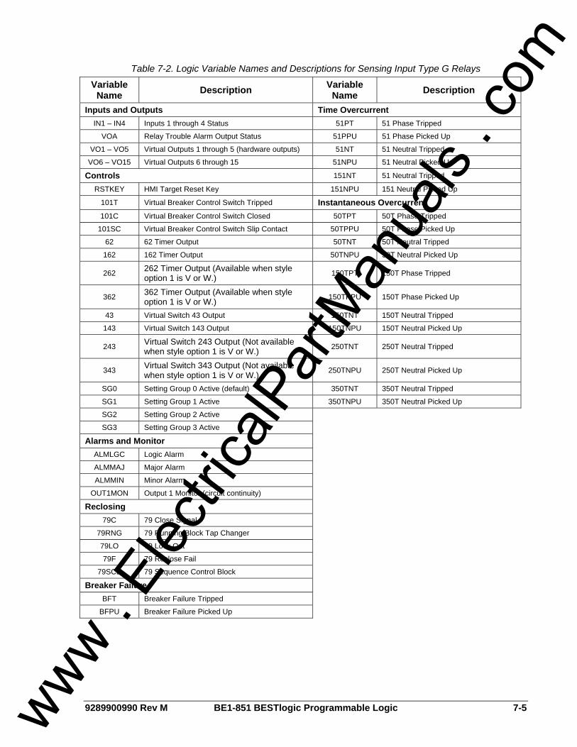
9289900990 Rev M BE1-851 BESTlogic Programmable Logic 7-5
Table 7-2. Logic Variable Names and Descriptions for Sensing Input Type G Relays
Variable Name Description Variable
Name Description
Inputs and Outputs Time Overcurrent IN1 – IN4 Inputs 1 through 4 Status 51PT 51 Phase Tripped
VOA Relay Trouble Alarm Output Status 51PPU 51 Phase Picked Up
VO1 – VO5 Virtual Outputs 1 through 5 (hardware outputs) 51NT 51 Neutral Tripped
VO6 – VO15 Virtual Outputs 6 through 15 51NPU 51 Neutral Picked Up
Controls 151NT 51 Neutral Tripped
RSTKEY HMI Target Reset Key 151NPU 151 Neutral Picked Up
101T Virtual Breaker Control Switch Tripped Instantaneous Overcurrent 101C Virtual Breaker Control Switch Closed 50TPT 50T Phase Tripped
101SC Virtual Breaker Control Switch Slip Contact 50TPPU 50T Phase Picked Up
62 62 Timer Output 50TNT 50T Neutral Tripped
162 162 Timer Output 50TNPU 50T Neutral Picked Up
262 262 Timer Output (Available when style option 1 is V or W.) 150TPT 150T Phase Tripped
362 362 Timer Output (Available when style option 1 is V or W.) 150TPPU 150T Phase Picked Up
43 Virtual Switch 43 Output 150TNT 150T Neutral Tripped
143 Virtual Switch 143 Output 150TNPU 150T Neutral Picked Up
243 Virtual Switch 243 Output (Not available when style option 1 is V or W.) 250TNT 250T Neutral Tripped
343 Virtual Switch 343 Output (Not available when style option 1 is V or W.) 250TNPU 250T Neutral Picked Up
SG0 Setting Group 0 Active (default) 350TNT 350T Neutral Tripped
SG1 Setting Group 1 Active 350TNPU 350T Neutral Picked Up
SG2 Setting Group 2 Active
SG3 Setting Group 3 Active
Alarms and Monitor ALMLGC Logic Alarm
ALMMAJ Major Alarm
ALMMIN Minor Alarm
OUT1MON Output 1 Monitor (circuit continuity)
Reclosing 79C 79 Close Signal
79RNG 79 Running/Block Tap Changer
79LO 79 Lock Out
79F 79 Reclose Fail
79SCB 79 Sequence Control Block
Breaker Failure BFT Breaker Failure Tripped
BFPU Breaker Failure Picked Up
www . El
ectric
alPar
tMan
uals
. com

7-6 BE1-851 BESTlogic Programmable Logic 9289900990 Rev M
Function Block Logic Settings Each BESTlogic function block is equivalent to its discrete device counterpart. For example, the Reclosing Logic Function Block of Figure 7-3 has many of the characteristics of a BE1-79M Relay.
Figure 7-3. 79 Reclosing Logic Function Block
Before using a protection or control function block, two items must be set: the mode and the input logic. Setting the Mode is equivalent to deciding which protection or control functions will be used in a logic scheme. The input logic establishes control of a function block. Mode and input logic information is contained in logic setting command strings. Depending on the command, the mode setting can either enable or disable a logic input or determine how a function block operates. Input logic defines which logic variables will control or disable a logic function. An example of an input BLOCK logic equation is IN3+VO6. The IN3+VO6 expression indicates that the 51P function is disabled when Input e (IN3) or Virtual Output 6 (VO6) is TRUE. The AND operator may not be applied to the terms of an input logic equation. Any number of variables or their inverse can be combined in a function block input logic expression. Section 4, Protection and Control, provides detailed information about setting the logic for each function block.
Output Logic Settings
Defining Output Operation Output operation is defined by Boolean logic equations. Each variable in an equation corresponds to the current state (evaluated every quarter cycle) of an input, output, or timer. Figure 7-4 illustrates this relationship. Every quarter cycle, output expressions are evaluated as TRUE or FALSE. If a logic output that corresponds to a hardware output changes state, then the corresponding output relay contact also changes state.
www . El
ectric
alPar
tMan
uals
. com
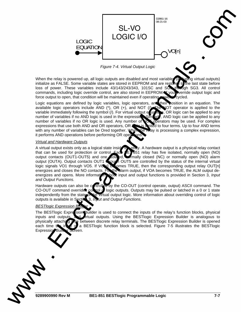
9289900990 Rev M BE1-851 BESTlogic Programmable Logic 7-7
VO[n]
LOGICEQUATION
D2861-1608-21-03
Figure 7-4. Virtual Output Logic When the relay is powered up, all logic outputs are disabled and most variables (including virtual outputs) initialize as FALSE. Some variable states are stored in EEPROM and are restored to the last state before loss of power. These variables include 43/143/243/343, 101SC and SG0 through SG3. All control commands, including logic override control, are also stored in EEPROM. If you override output logic and force output to open, that condition will be maintained even if operating power is cycled. Logic equations are defined by logic variables, logic operators, and their position in an equation. The available logic operators include AND (*), OR (+), and NOT (/). The NOT operator is applied to the variable immediately following the symbol (/). For virtual output equations, OR logic can be applied to any number of variables if no AND logic is used in the expression. Similarly, AND logic can be applied to any number of variables if no OR logic is used. Any number of NOT operators may be used. For complex expressions that use both AND and OR operators, OR logic is limited to four terms. Up to four AND terms with any number of variables can be Ored together. When the relay is processing a complex expression, it performs AND operations before performing OR operations.
Virtual and Hardware Outputs A virtual output exists only as a logical state inside the relay. A hardware output is a physical relay contact that can be used for protection or control. Each BE1-851 relay has five isolated, normally open (NO) output contacts (OUT1-OUT5) and one isolated, normally closed (NC) or normally open (NO) alarm output (OUTA). Output contacts OUT1 through OUT5 are controlled by the status of the internal virtual logic signals VO1 through VO5. If VO[n] becomes TRUE, then the corresponding output relay OUT[n] energizes and closes the NO contacts. For the alarm output, if VOA becomes TRUE, the ALM output de-energizes and opens. More information about input and output functions is provided in Section 3, Input and Output Functions. Hardware outputs can also be controlled by the CO-OUT (control operate, output) ASCII command. The CO-OUT command overrides control of logic outputs. Outputs may be pulsed or latched in a 0 or 1 state independently from the state of the virtual output logic. More information about overriding control of logic outputs is available in Section 3, Input and Output Functions.
BESTlogic Expression Builder The BESTlogic Expression Builder is used to connect the inputs of the relay’s function blocks, physical inputs and outputs, and virtual outputs. Using the BESTlogic Expression Builder is analogous to physically attaching wire between discrete relay terminals. The BESTlogic Expression Builder is opened each time the input of a BESTlogic function block is selected. Figure 7-5 illustrates the BESTlogic Expression Builder Screen.
www . El
ectric
alPar
tMan
uals
. com
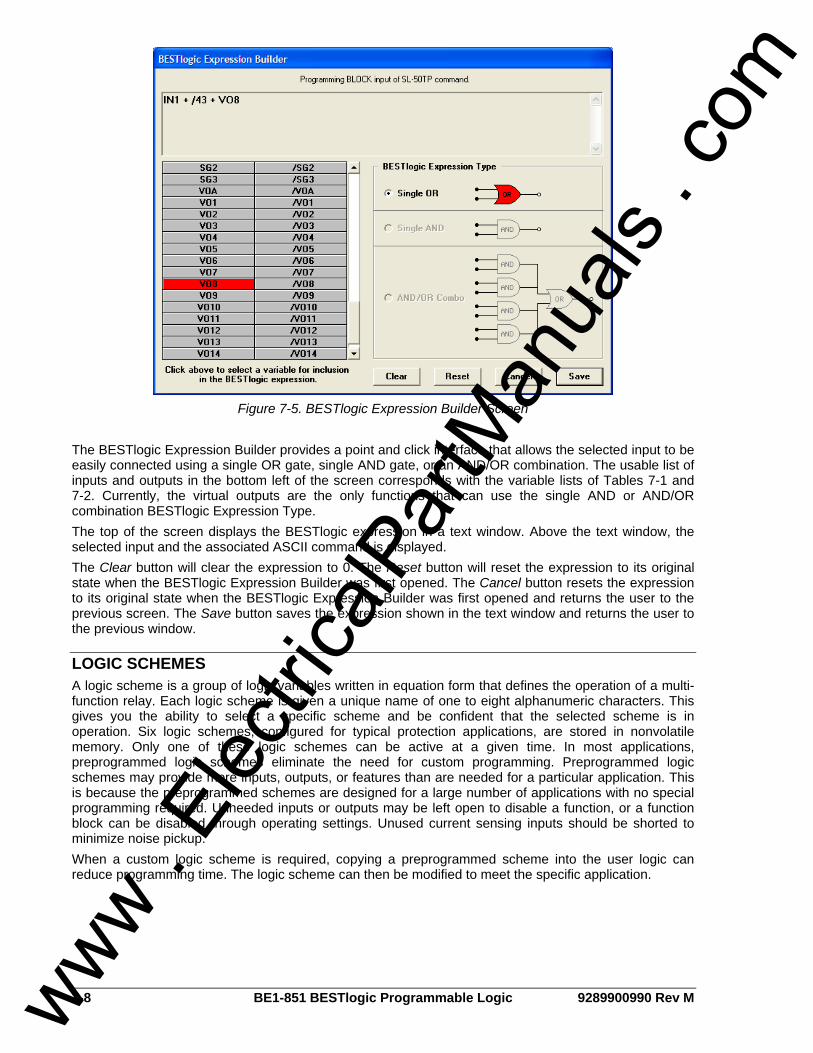
7-8 BE1-851 BESTlogic Programmable Logic 9289900990 Rev M
Figure 7-5. BESTlogic Expression Builder Screen
The BESTlogic Expression Builder provides a point and click interface that allows the selected input to be easily connected using a single OR gate, single AND gate, or an AND/OR combination. The usable list of inputs and outputs in the bottom left of the screen corresponds with the variable lists of Tables 7-1 and 7-2. Currently, the virtual outputs are the only functions that can use the single AND or AND/OR combination BESTlogic Expression Type. The top of the screen displays the BESTlogic expression in a text window. Above the text window, the selected input and the associated ASCII command is displayed. The Clear button will clear the expression to 0. The Reset button will reset the expression to its original state when the BESTlogic Expression Builder was first opened. The Cancel button resets the expression to its original state when the BESTlogic Expression Builder was first opened and returns the user to the previous screen. The Save button saves the expression shown in the text window and returns the user to the previous window.
LOGIC SCHEMES A logic scheme is a group of logic variables written in equation form that defines the operation of a multi-function relay. Each logic scheme is given a unique name of one to eight alphanumeric characters. This gives you the ability to select a specific scheme and be confident that the selected scheme is in operation. Six logic schemes, configured for typical protection applications, are stored in nonvolatile memory. Only one of these logic schemes can be active at a given time. In most applications, preprogrammed logic schemes eliminate the need for custom programming. Preprogrammed logic schemes may provide more inputs, outputs, or features than are needed for a particular application. This is because the preprogrammed schemes are designed for a large number of applications with no special programming required. Unneeded inputs or outputs may be left open to disable a function, or a function block can be disabled through operating settings. Unused current sensing inputs should be shorted to minimize noise pickup. When a custom logic scheme is required, copying a preprogrammed scheme into the user logic can reduce programming time. The logic scheme can then be modified to meet the specific application.
www . El
ectric
alPar
tMan
uals
. com
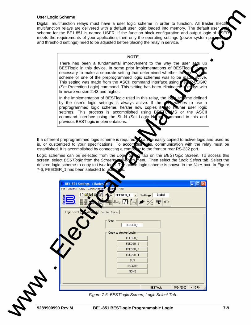
9289900990 Rev M BE1-851 BESTlogic Programmable Logic 7-9
User Logic Scheme Digital, multifunction relays must have a user logic scheme in order to function. All Basler Electric multifunction relays are delivered with a default user logic loaded into memory. The default user logic scheme for the BE1-851 is named USER. If the function block configuration and output logic of USER meets the requirements of your application, then only the operating settings (power system parameters and threshold settings) need to be adjusted before placing the relay in service.
If a different preprogrammed logic scheme is required, it can be easily copied to active logic and used as is, or customized to your specifications. To accomplish this, communication with the relay must be established. It is accomplished by connecting a computer to the front or rear RS-232 port. Logic schemes can be selected from the Logic Select tab on the BESTlogic Screen. To access this screen, select BESTlogic from the Screens pull-down menu. Then select the Logic Select tab. Select the desired logic scheme to copy to User logic. The active logic scheme is shown in the User box. In Figure 7-6, FEEDER_1 has been selected to user logic.
Figure 7-6. BESTlogic Screen, Logic Select Tab.
NOTE There has been a fundamental improvement to the way the user sets up BESTlogic in this device. In some prior implementations of BESTlogic, it was necessary to make a separate setting that determined whether the user’s logic scheme or one of the preprogrammed logic schemes was to be made active. This setting was made from the ASCII command interface using the SP-LOGIC (Set Protection Logic) command. This setting has been eliminated in relays with firmware version 2.43 and higher. In the implementation of BESTlogic used in this relay, the logic scheme defined by the user’s logic settings is always active. If the user wishes to use a preprogrammed logic scheme, he/she now copies it into his/her user logic settings. This process is accomplished using BESTCOMS or the ASCII command interface using the SL-N (Set Logic Name) command in this and previous BESTlogic implementations.
www . El
ectric
alPar
tMan
uals
. com

7-10 BE1-851 BESTlogic Programmable Logic 9289900990 Rev M
Custom Logic Schemes A custom logic scheme can be created from scratch by copying NONE to active logic and then renaming the logic. To rename a scheme, place the mouse pointer over the name shown in the User box. This will highlight the current name. Simply choose a name that is appropriate for your application and type the new name over the current name. Modifying one of the preprogrammed logic schemes after copying it to active logic and renaming can also create a custom logic scheme. Preprogrammed logic schemes copied to active logic with no name change are read-only schemes and cannot have their logic expressions altered. Before modifying a logic scheme copied to active logic, the scheme must be assigned a unique name of one to eight alphanumeric characters. This scheme is then referred to as a custom or user programmable logic scheme because the variable expressions of the logic can be customized or created from scratch to suit the needs of an application. A custom logic scheme may be revised many times, but only the most recent changes are saved to active logic.
Creating or Customizing a Logic Scheme Before customizing a preprogrammed logic scheme, the scheme must be renamed. The following procedure outlines the process of customizing or creating a logic scheme: Step 1. Copy the preprogrammed logic scheme. Step 2. Rename the scheme with a unique, non-preprogrammed name. Step 3. Using BESTCOMS, enable or disable the desired relay functions. Step 4. Edit the logic expressions as required. Step 5. Save the changes. Refer to Section 14, BESTCOMS Software, for more information on how to
save and export settings files.
Sending and Retrieving Relay Settings
Retrieving Relay Settings To retrieve settings from the relay, the relay must be connected to a computer through a serial port. Once the necessary connections are made, settings can be downloaded from the relay by selecting Download Settings from Device on the Communication pull-down menu.
CAUTION Selecting a logic scheme to be active in BESTCOMS does not automatically make that scheme active in the relay. See the paragraphs later in this section titled Sending and Retrieving Relay Settings.
NOTE A copied logic scheme must be renamed in order to become a custom logic scheme. If it is not renamed, you will not be allowed to change the settings associated with that scheme.
CAUTION Always remove the relay from service before changing or modifying the active logic scheme. Attempting a logic scheme change while the relay is in service could generate unexpected or unwanted outputs.
www . El
ectric
alPar
tMan
uals
. com

9289900990 Rev M BE1-851 BESTlogic Programmable Logic 7-11
Sending Relay Settings To send settings to the relay, the relay must be connected to a computer through a serial port. Once the necessary connections are made, settings can be uploaded to the relay by selecting Upload Settings to Device on the Communication pull-down menu.
Debugging the Logic Scheme If there are problems with a customized logic scheme, the RG-STAT command can be used to check the status of all logic variables. More information about the RG-STAT command can be found in Section 6, Reporting and Alarm Functions.
USER INPUT AND OUTPUT LOGIC VARIABLE NAMES Assigning meaningful names to the inputs and outputs makes sequential events reports easier to analyze. Input and output logic variable names are assigned by typing them into the appropriate text box on the related BESTCOMS screen. All of the BE1-851’s inputs, outputs, and 43 switches have labels that can be edited. Tables 7-3, 7-4, and 7-5 show the range and purpose of each label. Alternately, labels may be edited using the SN-[name]=[label] ASCII command.
Table 7-3. Label Settings for INPUTS
Setting Range/Purpose Default
Name 1 to 10 characters. User label to replace default label.
INPUT_x (where x = 1, 2, 3, or 4)
Energized State 1 to 7 characters. User label to replace default label.
TRUE
De-Energized State 1 to 7 characters. User label to replace default label.
FALSE
Table 7-4. Label Settings for OUTPUTS
Setting Range/Purpose Default
Label 1 to 10 characters. User label to replace default label.
VOx_LABEL (where x = 1, 2, 3, 4, 5, or A)
True State 1 to 7 characters. User label to replace default label.
TRUE
False State 1 to 7 characters. User label to replace default label.
FALSE
Table 7-5. Label Settings for 43 SWITCHES
Setting Range/Purpose Default
Label 1 to 10 characters. User label to replace default label.
SWITCH_x (where x = 43, 143, 243, or 343)
True State 1 to 7 characters. User label to replace default label.
TRUE
False State 1 to 7 characters. User label to replace default label.
FALSE
www . El
ectric
alPar
tMan
uals
. com

7-12 BE1-851 BESTlogic Programmable Logic 9289900990 Rev M
BESTLOGIC APPLICATION TIPS When designing a completely new logic scheme, logic evaluation order should be considered. Contact sensing inputs are evaluated first, then the function blocks and then the virtual outputs. VO15 is evaluated first and VOA is evaluated last. If a virtual output is used in a logic expression to control another virtual output, the virtual output used in the expression should be numerically higher. Otherwise, a logic expression for a numerically smaller virtual output will not be available to a numerically higher virtual output until the next processing interval. Logic is evaluated every quarter cycle. When designing custom protection schemes, avoid confusion by maintaining consistency between input and output functions in the custom scheme and the preprogrammed schemes. OUT1 through OUT5 have normally open contacts (coil is de-energized). Normally open contacts can be used as normally closed outputs by inverting the logic expressions that drive them. Inverting an output logic expression causes the coil to be energized with the contacts closed in the normal state. Caution should be taken with normally closed contact logic because there are no shorting bars to maintain the closed condition if the draw-out assembly is removed from the chassis. In applications where a normally closed output is needed even when the electronics are removed, a normally open contact from the relay can be used to drive a low-cost auxiliary relay. The normally closed output of the auxiliary relay will maintain the closed output when the draw-out assembly is removed from the case. Alternately, an external switch can be used to short across a normally closed relay output when the draw-out assembly is removed. Extra care is required to ensure that the switch is closed before removing the draw-out assembly and that the switch is open after the relay is placed back in service. Several links between the programmable alarm functions and BESTlogic programmable logic allow alarm functions to be used in a logic scheme and programmable logic functions to be used in the alarm reporting function. Programmable alarm settings for Major, Minor, and Logic alarms drive BESTlogic variables ALMMAJ, ALMMIN, and ALMLGC. These variables can be used in logic expressions to control logic when an alarm is active. Virtual outputs VO13, VO14, and VO15 are driven by BESTlogic expressions. These three logic variables are also available in the programmable alarm function. Virtual outputs can also be assigned user programmable labels (described previously). With this feature, a logic condition can be designed and used for an alarm. The virtual output label would then be reported in the alarm reporting function.
www . El
ectric
alPar
tMan
uals
. com

9289900990 Rev M BE1-851 Application i
SECTION 8 • APPLICATION TABLE OF CONTENTS
SECTION 8 • APPLICATION .................................................................................................................... 8-1
GENERAL.............................................................................................................................................. 8-1 EXPLANATION OF TERMS .................................................................................................................. 8-1 OVERVIEW OF PREPROGRAMMED LOGIC SCHEMES ................................................................... 8-2
Factory Default Logic Settings ........................................................................................................... 8-2 Feeder_1 Logic Scheme .................................................................................................................... 8-2 Feeder_2 Logic Scheme .................................................................................................................... 8-2 Feeder_3 Logic Scheme .................................................................................................................... 8-2 Feeder_4 Logic Scheme .................................................................................................................... 8-2 BUS Logic Scheme ............................................................................................................................ 8-2 BACKUP Logic Schemes ................................................................................................................... 8-2
DETAILS OF PREPROGRAMMED LOGIC SCHEMES........................................................................ 8-3 FACTORY DEFAULT LOGIC SETTINGS ............................................................................................. 8-3
Operation - Protection ........................................................................................................................ 8-3 Operation - Setting Group Selection .................................................................................................. 8-3 Operations - Alarms ........................................................................................................................... 8-3 Factory Default Logic Settings and Equations for Sensing Input Type H Relays .............................. 8-8 Factory Default Logic Settings and Equations for Sensing Input Type G Relays.............................. 8-8
FEEDER_1 LOGIC SCHEME................................................................................................................ 8-9 Normal Operation - Protection............................................................................................................ 8-9 Normal Operation - Setting Group Selection...................................................................................... 8-9 Normal Operation - Bus Protection .................................................................................................... 8-9 Normal Operation - Alarms............................................................................................................... 8-10 Contingency Operation - Test Mode ................................................................................................ 8-10 Contingency Operation - Backup Protection for Feeder Breaker Failure ........................................ 8-10 Contingency Operation - Backup Protection for Feeder Relay Out-of-Service................................ 8-10 Feeder_1 Logic Settings and Equations for Sensing Input Type H Relays ..................................... 8-16 Feeder_1 Logic Settings and Equations for Sensing Input Type G Relays..................................... 8-16
FEEDER_2 LOGIC SCHEME.............................................................................................................. 8-17 Normal Operation - Control .............................................................................................................. 8-17 Normal Operation - Protection.......................................................................................................... 8-17 Normal Operation - Reclosing.......................................................................................................... 8-17 Normal Operation - Setting Group Selection.................................................................................... 8-18 Normal Operation - Bus Protection .................................................................................................. 8-18 Normal Operation - Alarms............................................................................................................... 8-18 Contingency Operation - Test Mode ................................................................................................ 8-18 Contingency Operation - Backup Protection for Feeder Breaker Failure ........................................ 8-19 Contingency Operation - Backup Protection for Feeder Relay Out-of-Service................................ 8-19 Feeder_2 Logic Settings and Equations for Sensing Input Type H Relays ..................................... 8-25 Feeder_2 Logic Settings and Equations for Sensing Input Type G Relays..................................... 8-25
FEEDER_3 LOGIC SCHEME.............................................................................................................. 8-26 Normal Operation - Control .............................................................................................................. 8-26 Normal Operation - Protection.......................................................................................................... 8-26 Normal Operation - Reclosing.......................................................................................................... 8-26 Normal Operation - Setting Group Selection.................................................................................... 8-27 Normal Operation - Bus Protection .................................................................................................. 8-27 Normal Operation - Alarms............................................................................................................... 8-27 Contingency Operation - Test Mode ................................................................................................ 8-27 Contingency Operation - Backup Protection for Feeder Breaker Failure ........................................ 8-28 Contingency Operation - Backup Protection for Feeder Relay Out-of-Service................................ 8-28 Feeder_3 Logic Settings and Equations for Sensing Input Type H Relays ..................................... 8-34 Feeder_3 Logic Settings and Equations for Sensing Input Type G Relays..................................... 8-34
FEEDER_4 LOGIC SCHEME.............................................................................................................. 8-35 Normal Operation - Control .............................................................................................................. 8-35 Normal Operation - Protection.......................................................................................................... 8-35
www . El
ectric
alPar
tMan
uals
. com

ii BE1-851 Application 9289900990 Rev M
Normal Operation - Reclosing .......................................................................................................... 8-35 Normal Operation - Bus Protection .................................................................................................. 8-36 Normal Operation - Alarms............................................................................................................... 8-36 Contingency Operation - Test Mode ................................................................................................ 8-36 Contingency Operation - Backup Protection for Feeder Breaker Failure......................................... 8-37 Contingency Operation - Backup Protection for Feeder Relay Out-of-Service................................ 8-37 Feeder_4 Logic Settings and Equations for Sensing Input Type H Relays ..................................... 8-43 Feeder_4 Logic Settings and Equations for Sensing Input Type G Relays..................................... 8-43
BUS AND BACKUP LOGIC SCHEMES .............................................................................................. 8-44 Normal Operation - Control .............................................................................................................. 8-44 Normal Operation - Bus Protection .................................................................................................. 8-44 Normal Operation - Setting Group Selection.................................................................................... 8-45 Normal Operation - Alarms............................................................................................................... 8-45 Contingency Operation - Test Mode ................................................................................................ 8-45 Contingency Operation - Backup Protection for Bus Breaker Failure.............................................. 8-45 Contingency Operation - Backup Protection for BUS Relay Out-of-Service.................................... 8-46 Contingency Operation - Backup Protection for BACKUP Relay Out-of-Service ............................ 8-46 Contingency Operation - Backup Protection for Feeder Relay Out-of-Service................................ 8-46 BUS Logic Settings and Equations for Sensing Input Type H Relays ............................................. 8-52 BUS Logic Settings and Equations for Sensing Input Type H Relays ............................................. 8-52 BACKUP Logic Settings and Equations for Sensing Input Type H Relays...................................... 8-59 BACKUP Logic Settings and Equations for Sensing Input Type G Relays ..................................... 8-59
MISCELLANEOUS LOGIC SETTINGS ............................................................................................... 8-61 APPLICATION TIPS ............................................................................................................................ 8-61
Trip Circuit Continuity and Voltage Monitor...................................................................................... 8-61 Close Circuit Monitor ........................................................................................................................ 8-62 High-Speed Reclose ........................................................................................................................ 8-63 Block Load Tap Changer.................................................................................................................. 8-63 Block Neutral and Negative-Sequence Protection ........................................................................... 8-63 Setting Group Selection ................................................................................................................... 8-64 Output Contact Seal-In..................................................................................................................... 8-64 Oscillograhpic Recording of Breaker Closures and Openings......................................................... 8-65
Figures Figure 8-1. Typical One-Line Diagram for Factory Default Logic Settings................................................ 8-6 Figure 8-2. Factory Default Logic Settings Diagram ................................................................................. 8-7 Figure 8-3. Typical One-Line Diagram for Feeder_1 Logic ..................................................................... 8-14 Figure 8-4. Feeder_1 Logic Diagram....................................................................................................... 8-15 Figure 8-5. Typical One-Line Diagram for Feeder_2 Logic ..................................................................... 8-23 Figure 8-6. Feeder_2 Logic Diagram....................................................................................................... 8-24 Figure 8-7. Typical One-Line Diagram for Feeder_3 Logic ..................................................................... 8-32 Figure 8-8. Feeder_3 Logic Diagram....................................................................................................... 8-33 Figure 8-9. Typical One-Line Diagram for Feeder_4 Logic ..................................................................... 8-41 Figure 8-10. Feeder_4 Logic Diagram..................................................................................................... 8-42 Figure 8-11. Typical One-Line Diagram for BUS Logic ........................................................................... 8-50 Figure 8-12. BUS Logic Diagram............................................................................................................. 8-51 Figure 8-13. Typical One-Line Diagram for Backup Logic ...................................................................... 8-57 Figure 8-14. BACKUP Logic Diagram ..................................................................................................... 8-58 Figure 8-15. Interconnection Diagram for Integrated Protective System ................................................ 8-60 Figure 8-16. Trip Circuit Continuity and Voltage Monitor ........................................................................ 8-62 Figure 8-17. Close Circuit Monitor Logic ................................................................................................. 8-62 Figure 8-18. High-Speed Reclose Interlock Logic................................................................................... 8-63 Figure 8-19. Output Seal-In Logic Diagram............................................................................................. 8-65
Tables Table 8-1. Factory Default Contact Sensing Input Logic Settings............................................................. 8-3 Table 8-2. Factory Default Function Blocks Logic Settings....................................................................... 8-4 Table 8-3. Factory Default Virtual Switch Logic Settings .......................................................................... 8-4 Table 8-4. Factory Default Virtual Output Logic Settings .......................................................................... 8-5 Table 8-5. Feeder_1 Contact Sensing Input Logic.................................................................................. 8-10
www . El
ectric
alPar
tMan
uals
. com

9289900990 Rev M BE1-851 Application iii
Table 8-6. Feeder_1 Function Block Logic.............................................................................................. 8-11 Table 8-7. Feeder_1 Virtual Switches Logic............................................................................................ 8-12 Table 8-8. Feeder_1 Virtual Outputs ....................................................................................................... 8-12 Table 8-9. Feeder_2 Contact Sensing Input Logic.................................................................................. 8-19 Table 8-10. Feeder_2 Function Block Logic............................................................................................ 8-19 Table 8-11. Feeder_2 Virtual Switches Logic.......................................................................................... 8-21 Table 8-12. Feeder_2 Virtual Outputs ..................................................................................................... 8-21 Table 8-13. Feeder_3 Contact Sensing Input Logic................................................................................ 8-28 Table 8-14. Feeder_3 Function Block Logic............................................................................................ 8-29 Table 8-15. Feeder_3 Virtual Switches Logic.......................................................................................... 8-30 Table 8-16. Feeder_3 Virtual Outputs ..................................................................................................... 8-30 Table 8-17. Feeder_4 Contact Sensing Input Logic................................................................................ 8-37 Table 8-18. Feeder_4 Function Block Logic............................................................................................ 8-37 Table 8-19. Feeder_4 Virtual Switches Logic.......................................................................................... 8-39 Table 8-20. Feeder_4 Virtual Outputs ..................................................................................................... 8-39 Table 8-21. BUS Contact Sensing Input Logic........................................................................................ 8-47 Table 8-22. BUS Function Block Logic.................................................................................................... 8-47 Table 8-23. BUS Virtual Switch Logic ..................................................................................................... 8-48 Table 8-24. BUS Virtual Outputs ............................................................................................................. 8-48 Table 8-25. BACKUP Contact Sensing Input Logic ................................................................................ 8-53 Table 8-26. BACKUP Function Block Logic ............................................................................................ 8-53 Table 8-27. BACKUP Virtual Switch Logic .............................................................................................. 8-54 Table 8-28. BACKUP Virtual Outputs...................................................................................................... 8-55 Table 8-29. Miscellaneous Logic Expressions ........................................................................................ 8-61
www . El
ectric
alPar
tMan
uals
. com

iv BE1-851 Application 9289900990 Rev M
This page intentionally left blank.
www . El
ectric
alPar
tMan
uals
. com

9289900990 Rev M BE1-851 Application 8-1
SECTION 8 • APPLICATION GENERAL This section discusses application of the BE1-851 Overcurrent Protection System using the pre-programmed logic schemes. The Details of Preprogrammed Logic Schemes subsection describes the characteristics of each logic scheme and how they combine to create an overcurrent protection system for a radial system substation. A detailed description of each preprogrammed scheme is also provided. This section concludes with application tips for programming a custom logic scheme to meet the requirements of your application. The preprogrammed logic schemes are designed to accommodate most common distribution or sub-transmission radial system overcurrent coordination schemes. The protection engineer can choose a logic scheme that most closely meets his application practices and adapt it by changing the function block operation and settings. This eliminates the need to create a custom logic scheme. It should be noted that each preprogrammed logic scheme also illustrates typical ways of using or controlling various functions. The user may choose to create a custom logic scheme by mixing the logic from several of the preprogrammed schemes. The logic can also be modified to incorporate some of the features described in the application tips provided at the end of this section. The flexibility of BESTlogic allows the protection engineer to create a custom scheme that exactly meets the requirements of the application.
EXPLANATION OF TERMS The following terms and definitions will facilitate the understanding of the application discussions to follow. Function Block - A stand-alone protection or control function that is equivalent to its discrete component counterpart. Torque Control - Torque control refers to blocking the start of an overcurrent function block. The pickup and trip outputs are held to zero and the timing function is not allowed to operate. This is in contrast to merely blocking the trip output. This applies to all overcurrent function blocks including those that do not emulate induction disk type (51) relays. Virtual Switches - These logic switches emulate traditional switches used on relay and control panels such as the breaker control switch (101) and selector switches (43). Virtual switches may be operated via communication commands or the human-machine interface (HMI). Operation of these switches can be disabled or password protected if the user chooses not to use them without changing the preprogrammed BESTlogic schemes. Radial System - As used in this section, a radial system is one where the loads are fed from only one source at a time.
NOTE All preprogrammed schemes are shown for sensing input type H relays. Relays with sensing input type G do not have negative-sequence elements.
www . El
ectric
alPar
tMan
uals
. com

8-2 BE1-851 Application 9289900990 Rev M
OVERVIEW OF PREPROGRAMMED LOGIC SCHEMES There are six preprogrammed logic schemes available. Four logic schemes are intended for use on feeder breakers. Two schemes are intended for use on the bus main breaker. This is typically the low-side bank breaker of the step-down power transformer.
Factory Default Logic Settings BE1-851 relays are shipped from the factory with default logic settings that are designed to allow the relay to be used directly in applications that do not require any of the relays advanced features. These default settings provide a basic overcurrent protection scheme. The default setting for the logic scheme name is “USER”. This scheme can be modified as outlined in Section 7, BESTlogic Programmable Logic, Logic Schemes. However, if you choose to change these settings, the defaults can only be brought back through BESTCOMS, manual programming, or by reloading the entire factory defaults.
Feeder_1 Logic Scheme This logic scheme provides time and instantaneous overcurrent protection. Breaker failure protection is also included. Functions such as manual control and automatic reclosing are not included. Logic is provided to maintain feeder protection when the relay is out of service. A bus relay using the preprogrammed logic scheme BACKUP will be signaled to continue protection.
Feeder_2 Logic Scheme This logic scheme provides time and both high set and low set instantaneous overcurrent protection. Automatic reclosing is included with reclosing initiated by a protective trip (reclose initiate scheme). Breaker Failure and manual control functions are also included. Logic is included to signal a bus relay using the preprogrammed logic scheme BACKUP to provide feeder protection when the relay is out of service. This scheme is not provided when style option 1 is V or W.
Feeder_3 Logic Scheme This logic scheme provides time and both high set and low set instantaneous overcurrent protection. Automatic reclosing is included. Reclosing is initiated when the breaker opens. Reclosing is disabled after a manual trip by a control switch slip contact. Driving the recloser to lockout disables the recloser. Breaker Failure and manual control functions are also provided. Logic is included to signal a bus relay using preprogrammed logic scheme BACKUP to provide feeder protection when the relay is out of service. This scheme is not provided when style option 1 is V or W.
Feeder_4 Logic Scheme This logic scheme provides time and instantaneous overcurrent protection. Automatic reclosing is included. Reclosing is initiated when the breaker opens. Interrupting the reclose initiate input disables the recloser. Reclosing is disabled after a manual trip by a control switch slip contact. Breaker Failure and manual control functions are also included. Backup for an out of service relay is to be provided by redundant relays on the feeder breaker. Logic is included to interconnect with the redundant relays for an external breaker failure initiate and blocking of the external instantaneous. This scheme is not provided when style option 1 is V or W.
BUS Logic Scheme This logic scheme is applied to a bus main relay to provide primary bus overcurrent protection. It contains logic to interconnect with the feeder logic schemes to provide high-speed overcurrent protection for the bus under normal conditions. It also contains logic to trip the feeder breakers while the feeder relays using Feeder_1, Feeder_2, or Feeder_3 logic schemes are out of service. This scheme is not provided when style option 1 is V or W.
BACKUP Logic Schemes This logic scheme is applied to a bus main relay to provide backup bus overcurrent protection as well as breaker failure protection for the bus breaker under normal conditions. It also provides primary bus overcurrent protection when the relay using BUS logic is providing feeder protection or when the primary bus relay is out of service. This scheme is not provided when style option 1 is V or W.
www . El
ectric
alPar
tMan
uals
. com
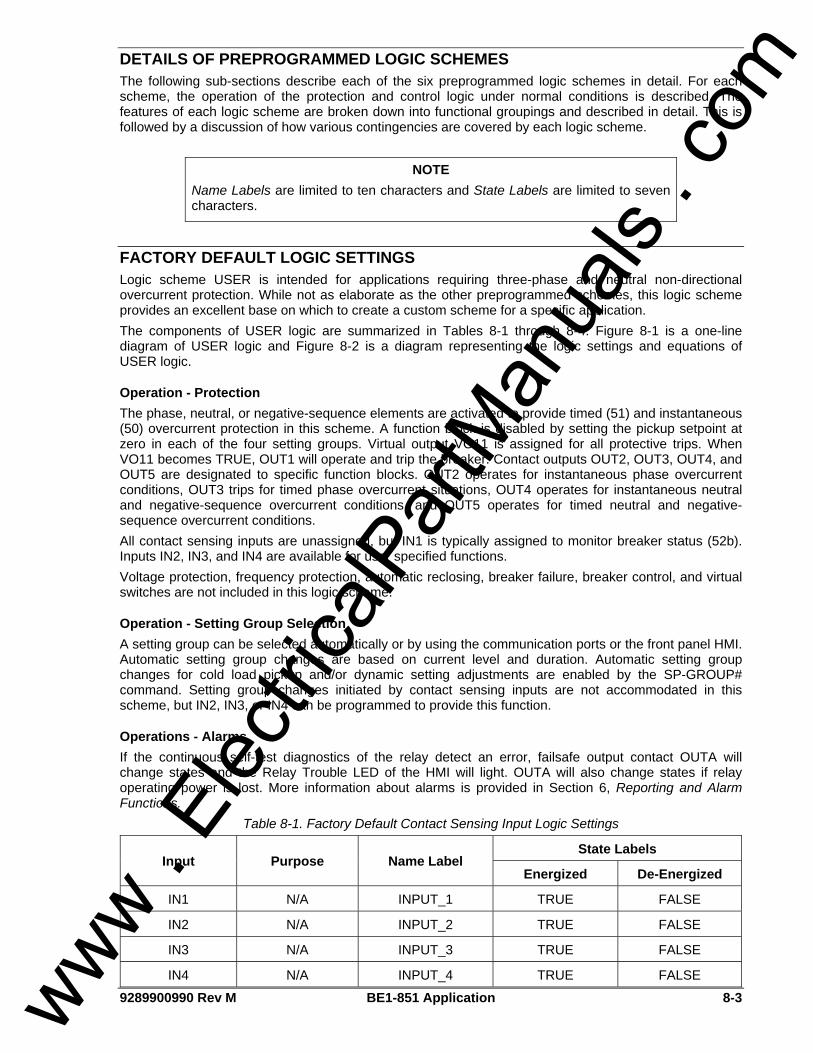
9289900990 Rev M BE1-851 Application 8-3
DETAILS OF PREPROGRAMMED LOGIC SCHEMES The following sub-sections describe each of the six preprogrammed logic schemes in detail. For each scheme, the operation of the protection and control logic under normal conditions is described. The features of each logic scheme are broken down into functional groupings and described in detail. This is followed by a discussion of how various contingencies are covered by each logic scheme.
FACTORY DEFAULT LOGIC SETTINGS Logic scheme USER is intended for applications requiring three-phase and neutral non-directional overcurrent protection. While not as elaborate as the other preprogrammed schemes, this logic scheme provides an excellent base on which to create a custom scheme for a specific application. The components of USER logic are summarized in Tables 8-1 through 8-4. Figure 8-1 is a one-line diagram of USER logic and Figure 8-2 is a diagram representing the logic settings and equations of USER logic.
Operation - Protection The phase, neutral, or negative-sequence elements are activated to provide timed (51) and instantaneous (50) overcurrent protection in this scheme. A function block is disabled by setting the pickup setpoint at zero in each of the four setting groups. Virtual output VO11 is assigned for all protective trips. When VO11 becomes TRUE, OUT1 will operate and trip the breaker. Contact outputs OUT2, OUT3, OUT4, and OUT5 are designated to specific function blocks. OUT2 operates for instantaneous phase overcurrent conditions, OUT3 trips for timed phase overcurrent situations, OUT4 operates for instantaneous neutral and negative-sequence overcurrent conditions, and OUT5 operates for timed neutral and negative-sequence overcurrent conditions. All contact sensing inputs are unassigned, but IN1 is typically assigned to monitor breaker status (52b). Inputs IN2, IN3, and IN4 are available for user specified functions. Voltage protection, frequency protection, automatic reclosing, breaker failure, breaker control, and virtual switches are not included in this logic scheme.
Operation - Setting Group Selection A setting group can be selected automatically or by using the communication ports or the front panel HMI. Automatic setting group changes are based on current level and duration. Automatic setting group changes for cold load pickup and/or dynamic setting adjustments are enabled by the SP-GROUP# command. Setting group changes initiated by contact sensing inputs are not accommodated in this scheme, but IN2, IN3, or IN4 can be programmed to provide this function.
Operations - Alarms If the continuous self-test diagnostics of the relay detect an error, failsafe output contact OUTA will change states and the Relay Trouble LED of the HMI will light. OUTA will also change states if relay operating power is lost. More information about alarms is provided in Section 6, Reporting and Alarm Functions.
Table 8-1. Factory Default Contact Sensing Input Logic Settings
State Labels Input Purpose Name Label
Energized De-Energized
IN1 N/A INPUT_1 TRUE FALSE
IN2 N/A INPUT_2 TRUE FALSE
IN3 N/A INPUT_3 TRUE FALSE
IN4 N/A INPUT_4 TRUE FALSE
NOTE Name Labels are limited to ten characters and State Labels are limited to seven characters.
www . El
ectric
alPar
tMan
uals
. com
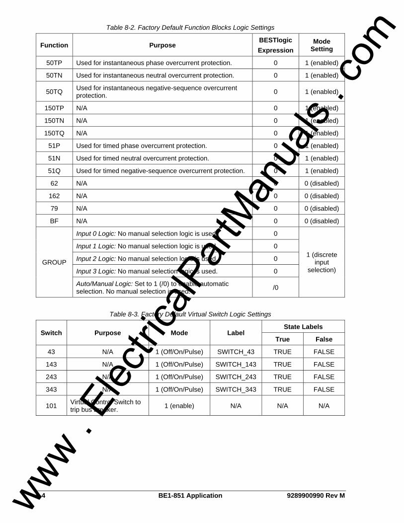
8-4 BE1-851 Application 9289900990 Rev M
Table 8-2. Factory Default Function Blocks Logic Settings
Function Purpose BESTlogic Expression
Mode Setting
50TP Used for instantaneous phase overcurrent protection. 0 1 (enabled)
50TN Used for instantaneous neutral overcurrent protection. 0 1 (enabled)
50TQ Used for instantaneous negative-sequence overcurrent protection. 0 1 (enabled)
150TP N/A 0 1 (enabled)
150TN N/A 0 1 (enabled)
150TQ N/A 0 1 (enabled)
51P Used for timed phase overcurrent protection. 0 1 (enabled)
51N Used for timed neutral overcurrent protection. 0 1 (enabled)
51Q Used for timed negative-sequence overcurrent protection. 0 1 (enabled)
62 N/A 0 0 (disabled)
162 N/A 0 0 (disabled)
79 N/A 0 0 (disabled)
BF N/A 0 0 (disabled)
Input 0 Logic: No manual selection logic is used. 0
Input 1 Logic: No manual selection logic is used. 0
Input 2 Logic: No manual selection logic is used. 0
Input 3 Logic: No manual selection logic is used. 0 GROUP
Auto/Manual Logic: Set to 1 (/0) to enable automatic selection. No manual selection is used. /0
1 (discrete input
selection)
Table 8-3. Factory Default Virtual Switch Logic Settings
State Labels Switch Purpose Mode Label
True False
43 N/A 1 (Off/On/Pulse) SWITCH_43 TRUE FALSE
143 N/A 1 (Off/On/Pulse) SWITCH_143 TRUE FALSE
243 N/A 1 (Off/On/Pulse) SWITCH_243 TRUE FALSE
343 N/A 1 (Off/On/Pulse) SWITCH_343 TRUE FALSE
101 Virtual Control Switch to trip bus breaker. 1 (enable) N/A N/A N/A
www . El
ectric
alPar
tMan
uals
. com

9289900990 Rev M BE1-851 Application 8-5
Table 8-4. Factory Default Virtual Output Logic Settings
State Labels Output Purpose Description Label
True False
VOA (OUTA)
Alarm Output Contact. Alarm contact changes states automatically when relay trouble alarm occurs. (Style dependent.)
ALARM ACTIVE NORMAL
BESTlogic Expression: VOA=0
VO1 (OUT1)
Breaker Trip Contact. Contact closes when protective trip expression is TRUE. BKR_TRIP TRIP NORMAL
BESTlogic Expression: VO1=VO11
VO2 (OUT2)
Instantaneous Phase Overcurrent Auxiliary Contact.
Contact closes when instantaneous phase overcurrent trip occurs.
50TP_TRIP TRIP NORMAL
BESTlogic Expression: VO2=50TPT
VO3 (OUT3)
Timed Phase Overcurrent Auxiliary Contact.
Contact closes when timed phase overcurrent trip occurs. 51P_TRIP TRIP NORMAL
BESTlogic Expression: VO3=51PT
VO4 (OUT4)
Instantaneous Neutral and Negative-Sequence Overcurrent.
Contact closes when instantaneous neutral or instantaneous negative-sequence overcurrent condition occurs.
INST_N&Q TRIP NORMAL
BESTlogic Expression: VO4=50TNT+50TQT
VO5 (OUT5)
Timed Neutral and Negative-Sequence Overcurrent.
Contact closes when timed neutral or timed negative-sequence overcurrent condition exists.
51N & QTRP TRIP NORMAL
BESTlogic Expression: VO5=51NT+51QT
VO6 N/A N/A VO6_LABEL TRUE FALSE
BESTlogic Expression: VO6=0
VO7 N/A N/A VO7_LABEL TRUE FALSE
BESTlogic Expression: VO7=0
VO8 N/A N/A VO8_LABEL TRUE FALSE
BESTlogic Expression: VO8=0
VO9 N/A N/A VO9_LABEL TRUE FALSE
BESTlogic Expression: VO9=0
VO10 N/A N/A VO10_LABEL TRUE FALSE
BESTlogic Expression: VO10=0
VO11 Protective Trip Expression.
TRUE when any 50 or 51 element times out. PROT_TRIP TRIP NORMAL
BESTlogic Expression: VO11=50TPT+50TNT+50TQT+51PT+51NT+51QT
www . El
ectric
alPar
tMan
uals
. com
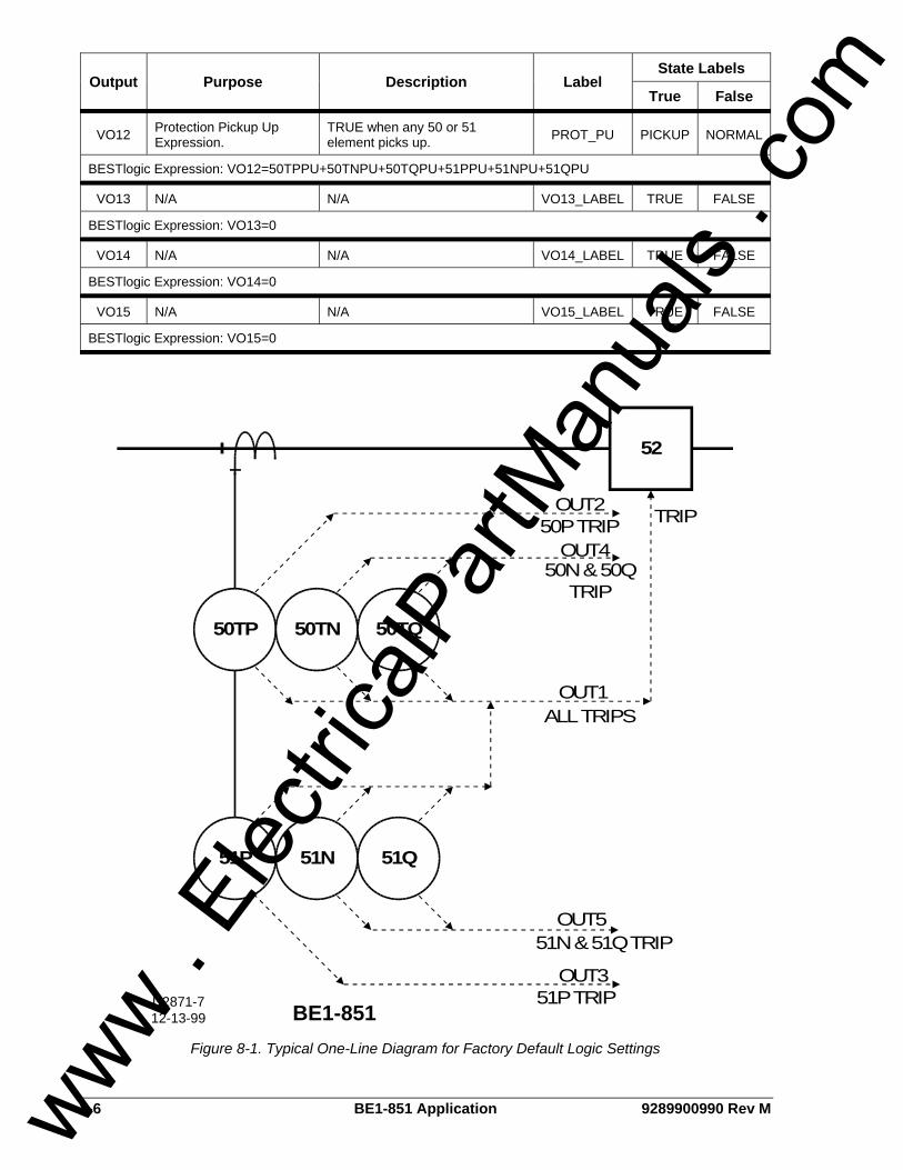
8-6 BE1-851 Application 9289900990 Rev M
State Labels Output Purpose Description Label
True False
VO12 Protection Pickup Up Expression.
TRUE when any 50 or 51 element picks up. PROT_PU PICKUP NORMAL
BESTlogic Expression: VO12=50TPPU+50TNPU+50TQPU+51PPU+51NPU+51QPU
VO13 N/A N/A VO13_LABEL TRUE FALSE
BESTlogic Expression: VO13=0
VO14 N/A N/A VO14_LABEL TRUE FALSE
BESTlogic Expression: VO14=0
VO15 N/A N/A VO15_LABEL TRUE FALSE
BESTlogic Expression: VO15=0
52
50TP 50TN 50TQ
51P 51N 51Q
OUT2
OUT4
OUT3
OUT5
OUT1
TRIP
BE1-851D2871-712-13-99
51P TRIP
51N & 51Q TRIP
ALL TRIPS
50N & 50QTRIP
50P TRIP
Figure 8-1. Typical One-Line Diagram for Factory Default Logic Settings
www . El
ectric
alPar
tMan
uals
. com
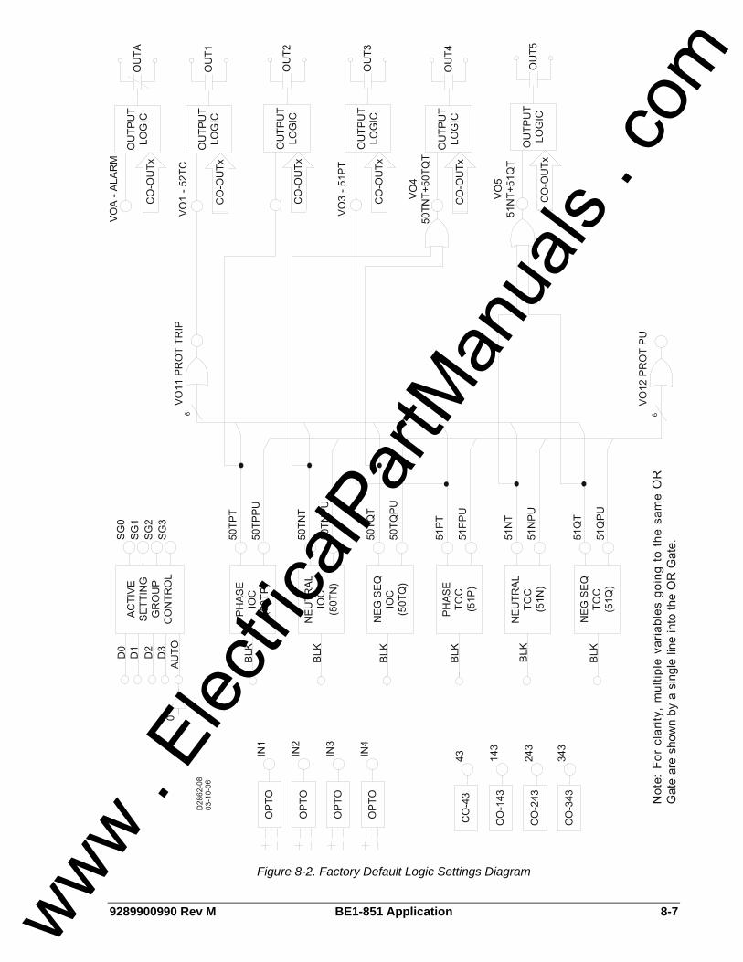
9289900990 Rev M BE1-851 Application 8-7
Figure 8-2. Factory Default Logic Settings Diagram
www . El
ectric
alPar
tMan
uals
. com
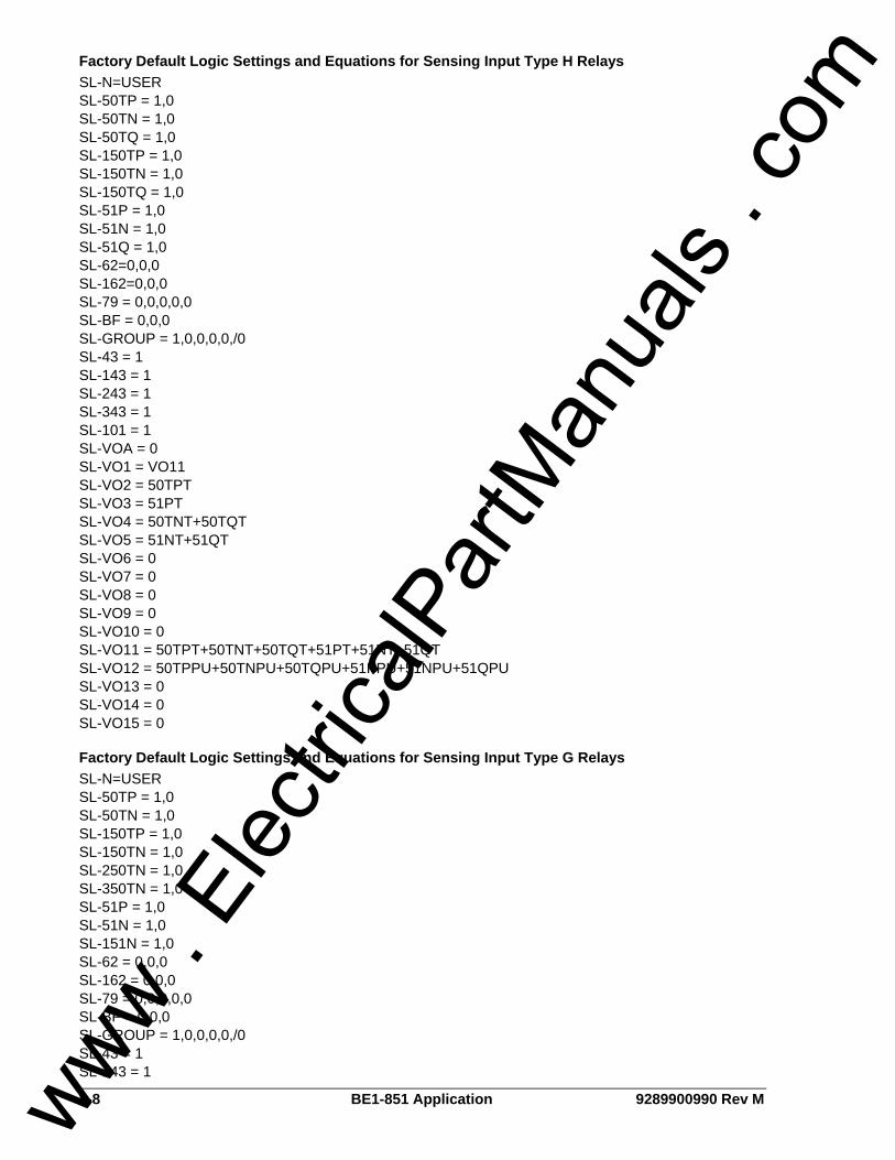
8-8 BE1-851 Application 9289900990 Rev M
Factory Default Logic Settings and Equations for Sensing Input Type H Relays SL-N=USER SL-50TP = 1,0 SL-50TN = 1,0 SL-50TQ = 1,0 SL-150TP = 1,0 SL-150TN = 1,0 SL-150TQ = 1,0 SL-51P = 1,0 SL-51N = 1,0 SL-51Q = 1,0 SL-62=0,0,0 SL-162=0,0,0 SL-79 = 0,0,0,0,0 SL-BF = 0,0,0 SL-GROUP = 1,0,0,0,0,/0 SL-43 = 1 SL-143 = 1 SL-243 = 1 SL-343 = 1 SL-101 = 1 SL-VOA = 0 SL-VO1 = VO11 SL-VO2 = 50TPT SL-VO3 = 51PT SL-VO4 = 50TNT+50TQT SL-VO5 = 51NT+51QT SL-VO6 = 0 SL-VO7 = 0 SL-VO8 = 0 SL-VO9 = 0 SL-VO10 = 0 SL-VO11 = 50TPT+50TNT+50TQT+51PT+51NT+51QT SL-VO12 = 50TPPU+50TNPU+50TQPU+51PPU+51NPU+51QPU SL-VO13 = 0 SL-VO14 = 0 SL-VO15 = 0
Factory Default Logic Settings and Equations for Sensing Input Type G Relays SL-N=USER SL-50TP = 1,0 SL-50TN = 1,0 SL-150TP = 1,0 SL-150TN = 1,0 SL-250TN = 1,0 SL-350TN = 1,0 SL-51P = 1,0 SL-51N = 1,0 SL-151N = 1,0 SL-62 = 0,0,0 SL-162 = 0,0,0 SL-79 = 0,0,0,0,0 SL-BF = 0,0,0 SL-GROUP = 1,0,0,0,0,/0 SL-43 = 1 SL-143 = 1
www . El
ectric
alPar
tMan
uals
. com

9289900990 Rev M BE1-851 Application 8-9
SL-243 = 1 SL-343 = 1 SL-101 = 1 SL-VOA = 0 SL-VO1 = VO11 SL-VO2 = 50TPT SL-VO3 = 51PT SL-VO4 = 50TNT SL-VO5 = 51NT SL-VO6 = 0 SL-VO7 = 0 SL-VO8 = 0 SL-VO9 = 0 SL-VO10 = 0 SL-VO11 = 50TPT+50TNT+51PT+51NT SL-VO12 = 50TPPU+50TNPU+51PPU+51NPU SL-VO13 = 0 SL-VO14 = 0 SL-VO15 = 0
FEEDER_1 LOGIC SCHEME Logic scheme Feeder_1 is meant for use on a feeder breaker and provides overcurrent and breaker failure protection for a typical feeder in a non-directional overcurrent protection application. This logic scheme is intended for use in conjunction with other programmable relays using the BUS and BACKUP logic schemes to provide protection when the relay is out of service. Automatic reclosing and other control functions such as virtual switches are not provided. When used with other programmable relays using logic scheme BUS and BACKUP, this scheme can provide complete high-speed overcurrent protection for the transformers. The components of Feeder_1 logic are summarized in Tables 8-5 through 8-8. Figure 8-3 is a one-line diagram of Feeder_1 logic and Figure 8-4 is a diagram representing the logic settings and equations of Feeder_1 logic.
Normal Operation - Protection The 51 function blocks and the breaker failure function block re-trip output are enabled in the logic for tripping via OUT1. The 50T function blocks are enabled in the logic for tripping through OUT2. Each overcurrent function block can be disabled by setting its pickup setting at 0 in each of the four setting groups. The 50T ground (N) and negative-sequence (Q), and the 51N and 51Q overcurrent function blocks are torque controlled by IN3. Modifying the inputs to these function blocks can disable all N & Q function blocks or only the 51N & Q function blocks.
Normal Operation - Setting Group Selection Setting group selection can be done automatically or by communications command/HMI override. Automatic setting group changes for cold load pickup and/or dynamic setting adjustments are enabled by the SP-GROUP# commands. Setting group changes initiate by a contact sensing input is not accommodated in this scheme. IN2, IN3, or IN4 can be reprogrammed to provide this function if desired. The automatic change logic can be disabled by IN2.
Normal Operation - Bus Protection When any of the 50T or 51 overcurrent function blocks is picked up, OUT4 closes. The signal from OUT4 is wired to IN2 of the upstream relay using BUS logic. The upstream relay blocks the 50T elements that are set to trip the bus breaker or bus lockout relay. If the fault is not on a feeder, the 50T elements of the bus relay are not blocked. The bus relay 50T elements are set with a time delay of 2 to 4 cycles to provide a minimal coordination interval for feeder relay OUT4 to close. Should there be a problem with the blocking logic, the bus relay 51 functions are not blocked to allow bus fault clearing with a traditional coordination interval. When used to provide high-speed overcurrent protection for the substation bus, it is recommended that all 51 function timing curves be set for instantaneous reset.
www . El
ectric
alPar
tMan
uals
. com

8-10 BE1-851 Application 9289900990 Rev M
Normal Operation - Alarms Two alarm logic variables drive the front panel alarm LEDs: Major alarm (ALMMAJ) and Minor alarm (ALMMIN). ALMMAJ is set to drive the fail-safe output OUTA. ALMMIN is not set to drive an output relay. The logic can be modified to place ALMMIN in the BESTlogic expression for VOA if all alarms are to be combined. ALMMIN can be placed in the BESTlogic expression for another output if it is desired that these conditions be enunciated separately.
Contingency Operation - Test Mode The test mode is intended to increase the security of the feeder protection system if external test switches are not installed on all outputs. When the relay is out of service for testing, the breaker failure and block upstream instantaneous functions are disabled. Backup by the upstream relay is enabled and the instantaneous function block trips are redirected to OUT1. De-energizing IN4 will put the logic scheme in the test mode. IN4 can be controlled by a panel mounted selector switch that is closed in the normal state and open in the test state. IN4 can also be controlled by a pole of a standard external test switch that is opened with the rest of the test switch poles. The logic expression for test mode drives Virtual Output 15 (VO15). This virtual output is alarm bit #23 in the programmable alarm mask. It can be masked to drive an alarm LED to provide indication when the relay is in test mode.
Contingency Operation - Backup Protection for Feeder Breaker Failure OUT5 is programmed as the breaker failure trip output. OUT5 can be wired to trip the bus breaker or a lockout relay. The breaker failure pickup (BFPU) output trips the feeder breaker directly via Output 1 to provide a breaker re-trip signal for added security. Initiation of the BF function block by external relays is not accommodated in this scheme. IN2, IN3, or IN4 can be programmed to provide this function or Feeder_4 logic may be used. The breaker failure function block is initiated by a protective trip. This function block has an independent fast drop out phase and ground current detector that detects a breaker opening and stops timing. An open breaker is detected when the current drops below 10% of nominal. Setting the time delay at zero can disable the BF function block. This permits the traditional radial systems backup scheme of coordinated relays tripping different breakers. Feeder_1 logic stops the block signal to allow the bus relay to trip the bus breaker through its 50T elements if a direct trip is not desired. This provides clearing of the fault on the circuit with the failed breaker in feeder relay breaker failure time (or bus relay 50T time whichever is greater) instead of the bus relay 51 time but is limited by the sensitivity constraints of the bus relay.
Contingency Operation - Backup Protection for Feeder Relay Out-of-Service When the relay is out of service or it has failed, OUT3 opens to signal the upstream relays providing backup protection. OUT3 operates in a fail-safe mode where the outputs are closed during normal operation and open during a relay failure. This provides backup mode signaling when the feeder relay is extracted from the case. Backup for relay failure can be implemented using the BUS and BACKUP preprogrammed logic schemes. These logic schemes are described later in this section.
Table 8-5. Feeder_1 Contact Sensing Input Logic
State Labels Input Purpose Name Label
Energized De-Energized
IN1 52b Breaker Status. BREAKER OPEN CLOSED
IN2 Automatic setting group change logic auto/manual switch. SETGRPAUTO ENABLED DISABLD
www . El
ectric
alPar
tMan
uals
. com

9289900990 Rev M BE1-851 Application 8-11
State Labels Input Purpose Name Label
Energized De-Energized
IN3 Enable neutral and negative-sequence, 50 and 51 protection when IN3 is energized.
N&Q_ENABLE ENABLED DISABLD
IN4
Put the relay in test mode so that breaker failure is disabled and all trips go through OUT1 when IN4 is de-energized.
TESTDISABL NORMAL TSTMODE
Table 8-6. Feeder_1 Function Block Logic
Function Purpose BESTlogic Expression
Mode Setting
50TP Used for instantaneous phase overcurrent protection. 0 1 (enabled)
50TN Used for instantaneous neutral overcurrent protection. Enabled when IN3 energized. /IN3 1 (enabled)
50TQ Used for instantaneous negative-sequence overcurrent protection. Enabled when IN3 energized. /IN3 1 (enabled)
150TP N/A 0 0 (disabled)
150TN N/A 0 0 (disabled)
150TQ N/A 0 0 (disabled)
51P Used for time phase overcurrent protection. 0 1 (enabled)
51N Used for timed neutral overcurrent protection. Enabled when IN3 energized. /IN3 1 (enabled)
51Q Used for timed negative-sequence overcurrent protection. Enabled when IN3 energized. /IN3 1 (enabled)
62 N/A 0 0 (disabled)
162 N/A 0 0 (disabled)
79 N/A 0 0 (disabled)
Initiate breaker failure when breaker failure initiate expression is TRUE. VO10
BF Block breaker failure protection when relay is in test mode. /IN4
1 (enabled)
No manual selection logic is used. 0
No manual selection logic is used. 0
No manual selection logic is used. 0
No manual selection logic is used. 0 GROUP
Disable automatic selection when switch connected to IN2 is in the manual position. IN2
1 (Discrete Inputs)
www . El
ectric
alPar
tMan
uals
. com

8-12 BE1-851 Application 9289900990 Rev M
Table 8-7. Feeder_1 Virtual Switches Logic
State Labels Switch Purpose Mode Label
True False
43 N/A 0 (Disable) SWITCH_43 CLOSED OPEN
143 N/A 0 (Disable) SWITCH_143 CLOSED OPEN
243 N/A 0 (Disable) SWITCH_243 CLOSED OPEN
343 N/A 0 (Disable) SWITCH_343 CLOSED OPEN
101 N/A 0 (Disable) N/A N/A N/A
Table 8-8. Feeder_1 Virtual Outputs
State Labels Output Purpose Description Label
True False
VOA (OUTA)
Alarm Output Contact. Changes state of alarm contact when relay failure or major programmable alarm is TRUE.
ALARM ACTIVE NORMAL
BESTlogic Expression: VOA=ALMMAJ
VO1 (OUT1)
50T Trip Output.
Close OUT1 when time overcurrent trip is TRUE or when breaker failure is initiated or when a protective trip occurs while in test mode.
51_TRIP TRIP NORMAL
BESTlogic Expression: VO1=VO8*IN4+BFPU+VO11*/IN4
VO2 (OUT2)
50T Trip Output. Trip breaker when instantaneous overcurrent trip is TRUE and not in test mode.
50_TRIP TRIP NORMAL
BESTlogic Expression: VO2=VO9*IN4
VO3 (OUT3)
Enable backup of relay by upstream relay.
Hold output closed if relay is not out of service because it is in test mode and it is not out of service due to relay failure
IN_SERVICE NORMAL BACKUP
BESTlogic Expression: VO3=IN4
VO4 (OUT4)
Block upstream instantaneous elements when relay is picked up for high-speed bus overcurrent protection logic.
Block upstream instantaneous elements when the protective pickup expression is TRUE and the relay is not in test mode and the breaker has not failed.
BLK_UPSTRM BLOCKED NORMAL
BESTlogic Expression: VO4=VO12*/VO5*IN4
VO5 (OUT5)
Breaker failure trip contact.
Trip backup if breaker failure protection times out. BKR_FAIL TRIP NORMAL
BESTlogic Expression: VO5=BFT
VO6 N/A N/A VO6 TRUE FALSE
BESTlogic Expression: VO6=0
www . El
ectric
alPar
tMan
uals
. com
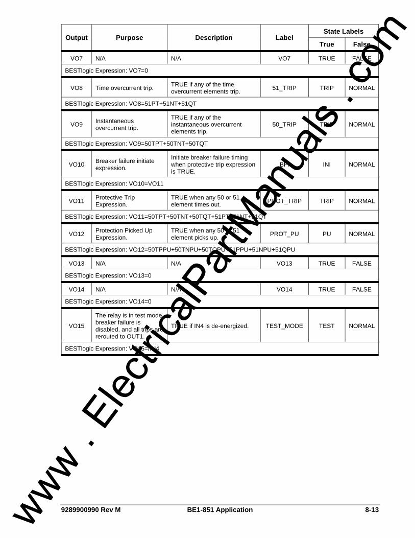
9289900990 Rev M BE1-851 Application 8-13
State Labels Output Purpose Description Label
True False
VO7 N/A N/A VO7 TRUE FALSE
BESTlogic Expression: VO7=0
VO8 Time overcurrent trip. TRUE if any of the time overcurrent elements trip. 51_TRIP TRIP NORMAL
BESTlogic Expression: VO8=51PT+51NT+51QT
VO9 Instantaneous overcurrent trip.
TRUE if any of the instantaneous overcurrent elements trip.
50_TRIP TRIP NORMAL
BESTlogic Expression: VO9=50TPT+50TNT+50TQT
VO10 Breaker failure initiate expression.
Initiate breaker failure timing when protective trip expression is TRUE.
BFI INI NORMAL
BESTlogic Expression: VO10=VO11
VO11 Protective Trip Expression.
TRUE when any 50 or 51 element times out. PROT_TRIP TRIP NORMAL
BESTlogic Expression: VO11=50TPT+50TNT+50TQT+51PT+51NT+51QT
VO12 Protection Picked Up Expression.
TRUE when any 50 or 51 element picks up. PROT_PU PU NORMAL
BESTlogic Expression: VO12=50TPPU+50TNPU+50TQPU+51PPU+51NPU+51QPU
VO13 N/A N/A VO13 TRUE FALSE
BESTlogic Expression: VO13=0
VO14 N/A N/A VO14 TRUE FALSE
BESTlogic Expression: VO14=0
VO15
The relay is in test mode, breaker failure is disabled, and all trips are rerouted to OUT1.
TRUE if IN4 is de-energized. TEST_MODE TEST NORMAL
BESTlogic Expression: VO15=/IN4
www . El
ectric
alPar
tMan
uals
. com
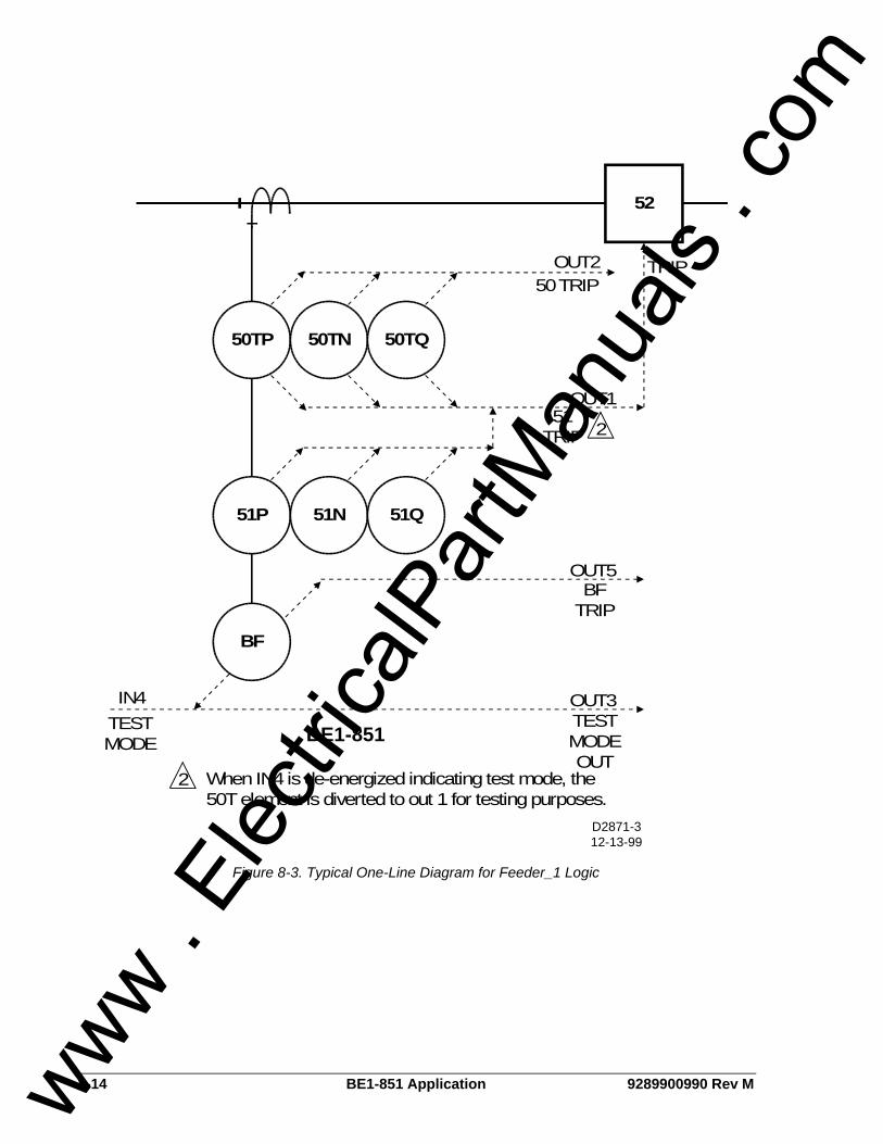
8-14 BE1-851 Application 9289900990 Rev M
52
50TP 50TN 50TQ
51P 51N 51Q
OUT2
IN4 OUT3
OUT5
OUT1
TRIP
BE1-851
D2871-312-13-99
BF
2
2 When IN4 is de-energized indicating test mode, the50T element is diverted to out 1 for testing purposes.
TESTMODE
TESTMODEOUT
BFTRIP
51TRIP
50 TRIP
Figure 8-3. Typical One-Line Diagram for Feeder_1 Logic
www . El
ectric
alPar
tMan
uals
. com
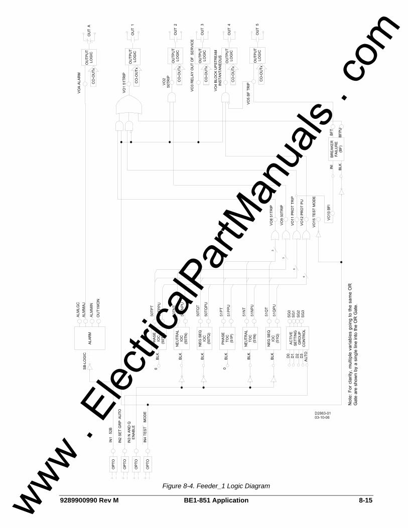
9289900990 Rev M BE1-851 Application 8-15
Figure 8-4. Feeder_1 Logic Diagram
www . El
ectric
alPar
tMan
uals
. com
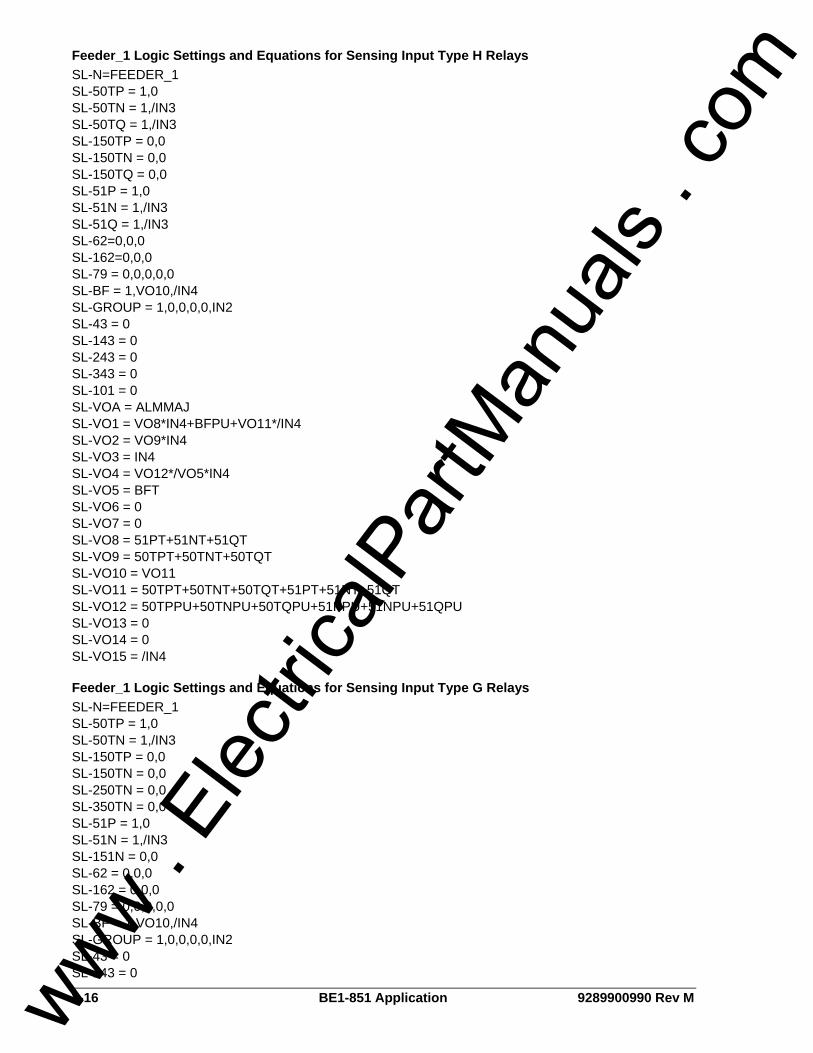
8-16 BE1-851 Application 9289900990 Rev M
Feeder_1 Logic Settings and Equations for Sensing Input Type H Relays SL-N=FEEDER_1 SL-50TP = 1,0 SL-50TN = 1,/IN3 SL-50TQ = 1,/IN3 SL-150TP = 0,0 SL-150TN = 0,0 SL-150TQ = 0,0 SL-51P = 1,0 SL-51N = 1,/IN3 SL-51Q = 1,/IN3 SL-62=0,0,0 SL-162=0,0,0 SL-79 = 0,0,0,0,0 SL-BF = 1,VO10,/IN4 SL-GROUP = 1,0,0,0,0,IN2 SL-43 = 0 SL-143 = 0 SL-243 = 0 SL-343 = 0 SL-101 = 0 SL-VOA = ALMMAJ SL-VO1 = VO8*IN4+BFPU+VO11*/IN4 SL-VO2 = VO9*IN4 SL-VO3 = IN4 SL-VO4 = VO12*/VO5*IN4 SL-VO5 = BFT SL-VO6 = 0 SL-VO7 = 0 SL-VO8 = 51PT+51NT+51QT SL-VO9 = 50TPT+50TNT+50TQT SL-VO10 = VO11 SL-VO11 = 50TPT+50TNT+50TQT+51PT+51NT+51QT SL-VO12 = 50TPPU+50TNPU+50TQPU+51PPU+51NPU+51QPU SL-VO13 = 0 SL-VO14 = 0 SL-VO15 = /IN4
Feeder_1 Logic Settings and Equations for Sensing Input Type G Relays SL-N=FEEDER_1 SL-50TP = 1,0 SL-50TN = 1,/IN3 SL-150TP = 0,0 SL-150TN = 0,0 SL-250TN = 0,0 SL-350TN = 0,0 SL-51P = 1,0 SL-51N = 1,/IN3 SL-151N = 0,0 SL-62 = 0,0,0 SL-162 = 0,0,0 SL-79 = 0,0,0,0,0 SL-BF = 1,VO10,/IN4 SL-GROUP = 1,0,0,0,0,IN2 SL-43 = 0 SL-143 = 0
www . El
ectric
alPar
tMan
uals
. com

9289900990 Rev M BE1-851 Application 8-17
SL-243 = 0 SL-343 = 0 SL-101 = 0 SL-VOA = ALMMAJ SL-VO1 = VO8*IN4+BFPU+VO11*/IN4 SL-VO2 = VO9*IN4 SL-VO3 = IN4 SL-VO4 = VO12*/IN5*IN4 SL-VO5 = BFT SL-VO6 = 0 SL-VO7 = 0 SL-VO8 = 51PT+51NT SL-VO9 = 50TPT+50TNT SL-VO10 = VO11 SL-VO11 = 50TPT+50TNT+51PT+51NT SL-VO12 = 50TPPU+50TNPU+51PPU+51NPU SL-VO13 = 0 SL-VO14 = 0 SL-VO15 = /IN4
FEEDER_2 LOGIC SCHEME Logic scheme Feeder_2 is meant for use on a feeder breaker and provides overcurrent, breaker failure protection, reclosing, and the control functions required for a typical feeder in a non-directional overcurrent protection application. This logic scheme is intended for use in conjunction with other programmable relays using the BUS and BACKUP logic schemes to provide protection when the relay is out of service. Automatic reclosing uses a reclose initiate scheme and is initiated by protective trip. When used with other programmable relays using logic scheme BUS and BACKUP, this scheme can provide complete high-speed overcurrent protection for the transformers, bus, and feeders in a radial system substations. The components of Feeder_2 logic are summarized in Tables 8-9 through 8-12. Figure 8-5 is a one-line diagram of Feeder_2 logic and Figure 8-6 represents the logic settings and equations of Feeder_2.
Normal Operation - Control The virtual breaker control switch is programmed to provide manual trip and close control of the breaker. The control functions of this logic scheme use both traditional contact sensing inputs and virtual switches. Virtual switches that are not needed may simply go unused. The protection engineer may choose to free up contact sensing inputs for other uses by using the virtual switches exclusively for the various control functions.
Normal Operation - Protection All overcurrent function blocks and the breaker failure function block re-trip output are enabled in Feeder_2 logic for tripping via OUT1. The 150T function blocks are set up as high set instantaneous functions which drive the recloser to lockout when they trip. Setting the pickup at 0 in the four setting groups can individually disable each overcurrent function block. The 50TN, 50TQ, 51N, and 51Q function blocks are torque controlled by either IN3 or virtual switch 243. All N and Q function blocks or only the 51N and 51Q function blocks may be inhibited. This is done in BESTlogic by modifying the inputs to the function blocks.
Normal Operation - Reclosing The reclosing logic in Feeder_2 uses a reclose initiate (RI) scheme where each step in the reclosing sequence is initiated by a protective trip. Setting the first reclose time at zero in the four setting groups can disable the recloser function block. Reclosing can be disabled by either IN2 or Virtual Switch 143 that is connected to the drive to lockout (DTL) input of the recloser function block. In this scheme, enabling the recloser after a “one shot” trip will
www . El
ectric
alPar
tMan
uals
. com

8-18 BE1-851 Application 9289900990 Rev M
cause the recloser to be in lockout. When the breaker is manually closed, the relay will time out to a reset condition. Drive to lockout also occurs if any of the 150TP/N/Q functions (typically used for high set instantaneous protection) trip or a breaker failure occurs. It should be noted that the 150TP/N/Q functions drive both the RI and the DTL inputs to the recloser function block. The DTL input takes priority over the RI input. Setting an appropriate logic expression for 79ZONE can enable zone-sequence coordination. Zone-sequence uses a BESTlogic expression but is not within the logic settings. The Feeder_2 logic scheme uses the expression SP-79ZONE=VO12. Feeder_2 logic provides for the recloser to torque control the 50TP/N/Q functions (typically used for low set instantaneous protection) during various steps in the reclosing sequence. Setting the recloser sequence controlled blocking output in the four setting groups is done using the S#-79SCB command. Recloser timing is stopped by the wait input if an overcurrent protection function block is picked up and timing. This prevents the reset timer from resetting the reclose function for a situation where a 51 element is just above pickup and the time to trip is longer than the reset time. Initiation of the recloser function block by external relays is not accommodated in this scheme. IN2, IN3, or IN4 can be reprogrammed to provide this function if desired. A block load tap changer output is not provided in this scheme. OUT5 can be reprogrammed as a 79RNG (recloser running/block tap changer) output and wired to energized normally closed auxiliary relay.
Normal Operation - Setting Group Selection Setting group selection can be done automatically or externally by communications command/HMI override. Automatic setting group changes for cold load pickup and/or dynamic setting adjustments are enabled by SP-GROUP# commands. Setting group changes initiated by contact sensing inputs are not accommodated in this scheme. IN2, IN3, or IN4 can be reprogrammed to provide this function if desired. Virtual Switch 43 can disable the automatic change logic.
Normal Operation - Bus Protection When any of the overcurrent function blocks are picked up, OUT4 closes. The signal from OUT4 is wired to IN2 of the upstream relay using BUS logic. The upstream relay blocks the 50T elements that are set up to trip the bus breaker or bus lockout relay. If the fault is not on a feeder, the 50T elements of the bus relay are not blocked. The bus relay 50T elements are set with a time delay of 2 to 4 cycles to provide a minimal coordination interval for the feeder relay OUT4 to close. Should there be a problem with the blocking logic, the bus relay 51 functions are not blocked to allow bus fault clearing with a traditional coordination interval.
Normal Operation - Alarms Two alarm logic variables drive the front panel alarm LEDs: Major alarm (ALMMAJ) and Minor alarm (ALMMIN). ALMMAJ is set to drive the fail-safe output OUTA. ALMMIN is not set to drive an output relay. The logic can be modified to place ALMMIN in the BESTlogic expression for VOA if all alarms are to be combined. ALMMIN can be placed in the BESTlogic expression for another output if it is desired that these conditions be enunciated separately.
Contingency Operation - Test Mode The test mode is intended to increase the security of the feeder protection and control system if external test switches are not installed on all outputs. When the relay is out of service for testing, the breaker failure, automatic reclosing, and block upstream instantaneous functions are disabled. Backup by the upstream relay is enabled. De-energizing IN4 or closing Virtual Switch 343 will put the logic scheme in the test mode. IN4 can be controlled by a panel mounted selector switch that is closed in the normal state and open in the test state. IN4 can also be controlled by a pole of a standard external test switch that is opened with the rest of the test switch poles. The logic expression for test mode drives virtual output 15 (VO15). This virtual output is alarm bit #23 in the programmable alarm mask. It can be masked to drive an alarm LED to provide indication when the relay is in test mode.
www . El
ectric
alPar
tMan
uals
. com

9289900990 Rev M BE1-851 Application 8-19
Contingency Operation - Backup Protection for Feeder Breaker Failure OUT5 is configured as the breaker failure trip output. OUT5 can be wired to trip the bus breaker or a lockout relay. The breaker failure pickup (BFPU) output trips the feeder breaker directly via output 1 to provide a breaker re-trip signal for added security. Initiation of the BF function block by external relays is not accommodated in this scheme. IN2, IN3, or IN4 can be programmed to provide this function or Feeder_4 logic may be used. The breaker failure function block is initiated by a protective trip. This function block has an independent fast drop out phase and ground current detector that detects a breaker opening and stops timing. An open breaker is detected when the current drops below 10 percent of nominal. Setting the time delay at zero disables the BF function block. This permits the traditional radial system backup scheme of coordinated relays tripping different breakers. Feeder_2 logic stops the block signal to allow the bus relay to trip the bus breaker through its 50T elements if a direct trip is not desired. This provides clearing of the fault on the circuit with the failed breaker in feeder relay breaker time (or bus relay 50T time; whichever is greater) instead of the bus relay 51 time but is limited by the sensitivity constraints of the bus relay.
Contingency Operation - Backup Protection for Feeder Relay Out-of-Service When the relay is out of service or it has failed, OUT3 opens to signal the upstream relays providing backup protection. OUT3 operates in a fail-safe mode; the output is closed during normal operation and open during a relay failure. This provides backup mode signaling when the feeder relay is extracted from the case. Backup for relay failure can be implemented using the BUS and BACKUP preprogrammed logic schemes. These logic schemes are described later in this section.
Table 8-9. Feeder_2 Contact Sensing Input Logic
State Labels Input Purpose Name Label
Energized De-Energized
IN1 52b Breaker Status. BREAKER OPEN CLOSED
IN2 Enable recloser when IN2 is energized. RCL_ENABLE ENABLED DISABLD
IN3 Enable neutral and negative-sequence, 50 and 51 protection when IN3 is energized.
N&Q_ENABLE ENABLED DISABLD
IN4 Put the relay in test mode so that reclosing and breaker failure are disabled when IN4 is de-energized.
TESTDISABL NORMAL TSTMODE
Table 8-10. Feeder_2 Function Block Logic
Function Purpose BESTlogic Expression
Mode Setting
50TP Used for instantaneous phase overcurrent protection. Block when recloser sequence controlled blocking output is TRUE.
79SCB 1 (enabled)
50TN
Used for instantaneous neutral overcurrent protection. Block when recloser sequence controlled blocking output is TRUE or when disabled by IN3 or Virtual Switch 243.
79SCB+/IN3+243 1 (enabled)
www . El
ectric
alPar
tMan
uals
. com

8-20 BE1-851 Application 9289900990 Rev M
Function Purpose BESTlogic Expression
Mode Setting
50TQ
Used for instantaneous negative-sequence overcurrent protection. Block when recloser sequence controlled blocking output is TRUE or when disabled by /IN3 or Virtual Switch 243.
79SCB+/IN3+243 1 (enabled)
150TP Used for instantaneous phase overcurrent protection. 0 1 (enabled)
150TN Used for instantaneous neutral overcurrent protection. 0 1 (enabled)
150TQ Used for instantaneous negative-sequence overcurrent protection. 0 1 (enabled)
51P Used for timed phase overcurrent protection. 0 1 (enabled)
51N Used for timed neutral overcurrent protection. Block when disabled by IN3 or Virtual Switch 243. /IN3+243 1 (enabled)
51Q Used for timed negative-sequence overcurrent protection. Block when disabled by IN3 or Virtual Switch 243.
/IN3+243 1 (enabled)
62 N/A 0 0 (disabled)
162 N/A 0 0 (disabled)
RI Logic: Initiate when reclose initiate expression is TRUE. VO8
STATUS Logic: Breaker closed when IN1 is de-energized. /IN1
WAIT Logic: Stop recloser timing when timing for a fault trip. TRUE when protection picked up expression is TRUE.
VO12 79
BLK/DTL Logic: Drive recloser to lockout when recloser drive to lockout expression is TRUE or when relay is in test mode.
VO9+/IN4+343
1 (Power Up to Lockout)
Initiate breaker failure when breaker failure initiate expression is TRUE. VO10
BF Block breaker failure protection when relay is in test mode. /IN4+343
1 (enabled)
No manual selection logic is used. 0
No manual selection logic is used. 0
No manual selection logic is used. 0
No manual selection logic is used. 0 GROUP
Disable automatic selection when Virtual Switch 43 is in the manual position. /43
1 (Discrete Inputs)
www . El
ectric
alPar
tMan
uals
. com

9289900990 Rev M BE1-851 Application 8-21
Table 8-11. Feeder_2 Virtual Switches Logic
State Labels Switch Purpose Mode Label
True False
43 Automatic setting group change logic auto/manual switch. 2 (On/Off) SETGRP_MAN MANUAL AUTO
143 Disable recloser when virtual switch is closed. 2 (On/Off) RCL_DISABL DISABLD ENABLED
243 Disable neutral and negative-sequence, 50 and 51 protection when virtual switch is closed.
2 (On/Off) N&Q_DISABL DISABLD ENABLED
343
Put the relay in test mode so that reclosing and breaker failure are disabled when virtual switch is closed.
2 (On/Off) TESTENABLE TSTMODE NORMAL
101 Virtual Control Switch to trip bus breaker. 1 (Enable) N/A N/A N/A
Table 8-12. Feeder_2 Virtual Outputs
State Labels Output Purpose Description Label
True False
VOA (OUTA)
Alarm Output Contact. Change state of alarm contact when relay failure or major programmable alarm is TRUE.
ALARM ACTIVE NORMAL
BESTlogic Expression: VOA=ALMMAJ
VO1 (OUT1)
Breaker trip contact.
Trip breaker when protective trip expression is TRUE or when breaker failure is initiated or when virtual breaker control switch is operated to trip
51_TRIP TRIP NORMAL
BESTlogic Expression: VO1=VO11+BFPU+101T
VO2 (OUT2)
Breaker close contact.
Close breaker when recloser close output it TRUE or when virtual breaker control switch is operated to close.
50_TRIP CLOSE NORMAL
BESTlogic Expression: VO2=79C+101C
VO3 (OUT3)
Enable backup of relay by upstream relay.
Hold output closed if relay is not out of service because it is in test mode and it is not out of service due to relay failure
IN_SERVICE NORMAL BACKUP
BESTlogic Expression: VO3=IN4*/343
VO4 (OUT4)
Block upstream instantaneous elements when relay is picked up for high-speed bus overcurrent protection logic.
Block upstream instantaneous elements when the protective pickup expression is TRUE and the relay is not in test mode and the breaker has not failed.
BLK_UPSTRM BLOCKED NORMAL
BESTlogic Expression: VO4=VO12*/VO5*IN4*/343
www . El
ectric
alPar
tMan
uals
. com
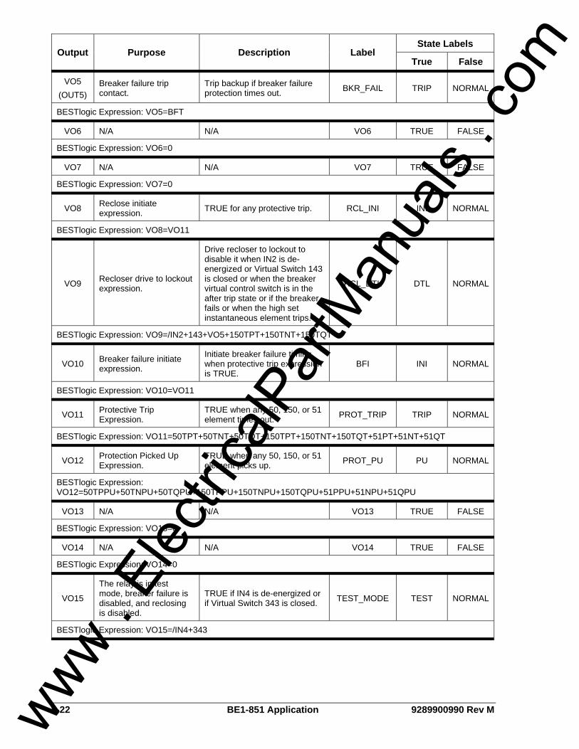
8-22 BE1-851 Application 9289900990 Rev M
State Labels Output Purpose Description Label
True False
VO5 (OUT5)
Breaker failure trip contact.
Trip backup if breaker failure protection times out. BKR_FAIL TRIP NORMAL
BESTlogic Expression: VO5=BFT
VO6 N/A N/A VO6 TRUE FALSE
BESTlogic Expression: VO6=0
VO7 N/A N/A VO7 TRUE FALSE
BESTlogic Expression: VO7=0
VO8 Reclose initiate expression. TRUE for any protective trip. RCL_INI INI NORMAL
BESTlogic Expression: VO8=VO11
VO9 Recloser drive to lockout expression.
Drive recloser to lockout to disable it when IN2 is de-energized or Virtual Switch 143 is closed or when the breaker virtual control switch is in the after trip state or if the breaker fails or when the high set instantaneous element trips.
RCL_DTL DTL NORMAL
BESTlogic Expression: VO9=/IN2+143+VO5+150TPT+150TNT+150TQT
VO10 Breaker failure initiate expression.
Initiate breaker failure timing when protective trip expression is TRUE.
BFI INI NORMAL
BESTlogic Expression: VO10=VO11
VO11 Protective Trip Expression.
TRUE when any 50, 150, or 51 element times out. PROT_TRIP TRIP NORMAL
BESTlogic Expression: VO11=50TPT+50TNT+50TQT+150TPT+150TNT+150TQT+51PT+51NT+51QT
VO12 Protection Picked Up Expression.
TRUE when any 50, 150, or 51 element picks up. PROT_PU PU NORMAL
BESTlogic Expression: VO12=50TPPU+50TNPU+50TQPU+150TPPU+150TNPU+150TQPU+51PPU+51NPU+51QPU
VO13 N/A N/A VO13 TRUE FALSE
BESTlogic Expression: VO13=0
VO14 N/A N/A VO14 TRUE FALSE
BESTlogic Expression: VO14=0
VO15
The relay is in test mode, breaker failure is disabled, and reclosing is disabled.
TRUE if IN4 is de-energized or if Virtual Switch 343 is closed. TEST_MODE TEST NORMAL
BESTlogic Expression: VO15=/IN4+343
www . El
ectric
alPar
tMan
uals
. com
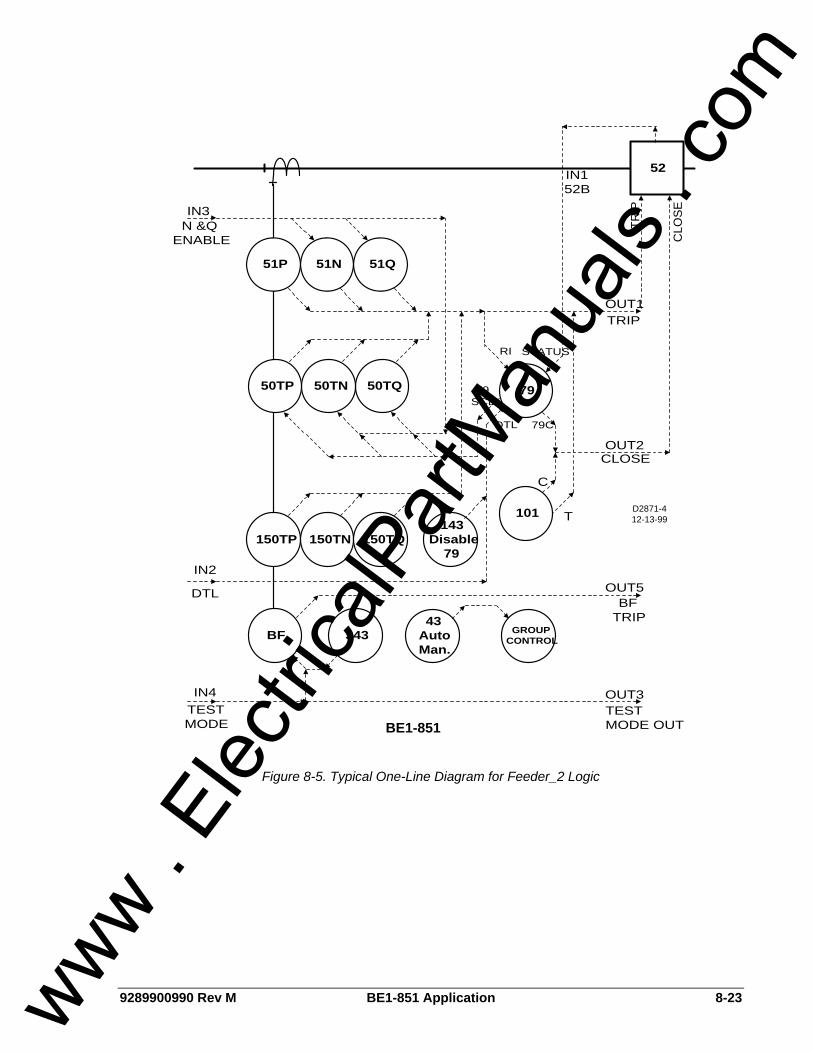
9289900990 Rev M BE1-851 Application 8-23
52
CLO
SE
51P 51N 51Q
D2871-412-13-99
OUT1
TRIP
TRIP
79
T
C
101
79C
RI
IN3N &Q
ENABLE
79SCB
50TQ50TN50TP
BE1-851
OUT3
GROUPCONTROL
43AutoMan.
343
OUT5
BF
BFTRIP
IN4TESTMODE
TESTMODE OUT
150TP 150TN 150TQ
DTL
OUT2CLOSE
143Disable
79IN2
DTL
STATUS
IN152B
Figure 8-5. Typical One-Line Diagram for Feeder_2 Logic
www . El
ectric
alPar
tMan
uals
. com
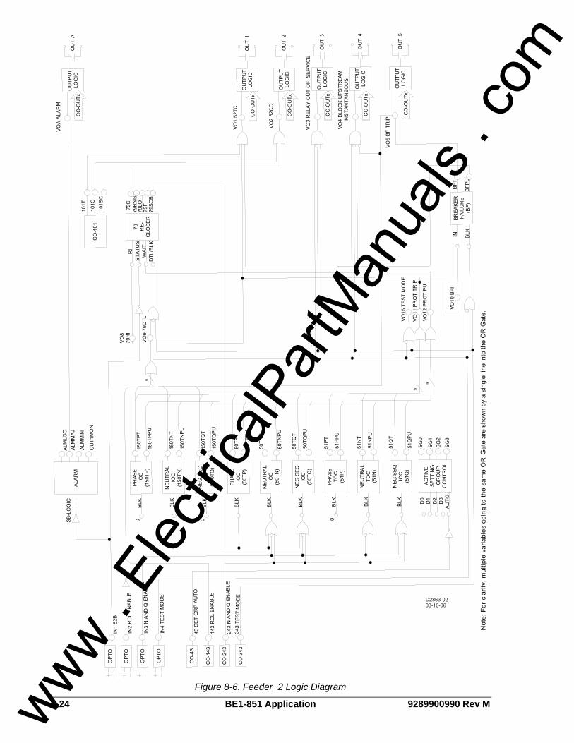
8-24 BE1-851 Application 9289900990 Rev M
Figure 8-6. Feeder_2 Logic Diagram
www . El
ectric
alPar
tMan
uals
. com
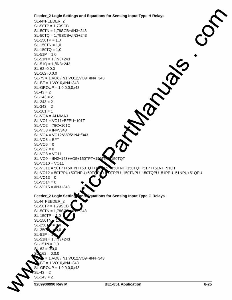
9289900990 Rev M BE1-851 Application 8-25
Feeder_2 Logic Settings and Equations for Sensing Input Type H Relays SL-N=FEEDER_2 SL-50TP = 1,79SCB SL-50TN = 1,79SCB+/IN3+243 SL-50TQ = 1,79SCB+/IN3+243 SL-150TP = 1,0 SL-150TN = 1,0 SL-150TQ = 1,0 SL-51P = 1,0 SL-51N = 1,/IN3+243 SL-51Q = 1,/IN3+243 SL-62=0,0,0 SL-162=0,0,0 SL-79 = 1,VO8,/IN1,VO12,VO9+/IN4+343 SL-BF = 1,VO10,/IN4+343 SL-GROUP = 1,0,0,0,0,/43 SL-43 = 2 SL-143 = 2 SL-243 = 2 SL-343 = 2 SL-101 = 1 SL-VOA = ALMMAJ SL-VO1 = VO11+BFPU+101T SL-VO2 = 79C+101C SL-VO3 = IN4*/343 SL-VO4 = VO12*/VO5*IN4*/343 SL-VO5 = BFT SL-VO6 = 0 SL-VO7 = 0 SL-VO8 = VO11 SL-VO9 = /IN2+143+VO5+150TPT+150TNT+150TQT SL-VO10 = VO11 SL-VO11 = 50TPT+50TNT+50TQT+150TPT+150TNT+150TQT+51PT+51NT+51QT SL-VO12 = 50TPPU+50TNPU+50TQPU+150TPPU+150TNPU+150TQPU+51PPU+51NPU+51QPU SL-VO13 = 0 SL-VO14 = 0 SL-VO15 = /IN3+343
Feeder_2 Logic Settings and Equations for Sensing Input Type G Relays SL-N=FEEDER_2 SL-50TP = 1,79SCB SL-50TN = 1,78SCB+/IN3+243 SL-150TP = 1,0 SL-150TN = 1,0 SL-250TN = 0,0 SL-350TN = 0,0 SL-51P = 1,0 SL-51N = 1,/IN3+243 SL-151N = 0,0 SL-62 = 0,0,0 SL-162 = 0,0,0 SL-79 = 1,VO8,/IN1,VO12,VO9+/IN4+343 SL-BF = 1,VO10,/IN4+343 SL-GROUP = 1,0,0,0,0,/43 SL-43 = 2 SL-143 = 2
www . El
ectric
alPar
tMan
uals
. com

8-26 BE1-851 Application 9289900990 Rev M
SL-243 = 2 SL-343 = 2 SL-101 = 1 SL-VOA = ALMMAJ SL-VO1 = VO11+BFPU+101T SL-VO2 = 79C+101C SL-VO3 = IN4*/343 SL-VO4 = VO12*/VO5*IN4*/343 SL-VO5 = BFT SL-VO6 = 0 SL-VO7 = 0 SL-VO8 = VO11 SL-VO9 = /IN2+143+/101SC+VO5+150TPT+150TNT SL-VO10 = VO11 SL-VO11 = 50TPT+50TNT+150TPT+150TNT+51PT+51NT SL-VO12 = 50TPPU+50TNPU+150TPPU+150TNPU+51PPU+51NPU SL-VO13 = 0 SL-VO14 = 0 SL-VO15 = /IN4+343
FEEDER_3 LOGIC SCHEME Logic scheme Feeder_3 is meant for use on a feeder breaker and provides all overcurrent and breaker failure protection, reclosing, and control functions required for a typical feeder in a non-directional overcurrent protection application. This logic scheme is intended for use in conjunction with other programmable relays using BUS and BACKUP schemes to provide protection when the relay is out of service. Automatic reclosing is initiated by the breaker opening. Reclosing is disabled after a manual trip by a control switch slip contact. In this logic scheme, the disable logic is connected to the drive to lockout (DTL) input. The recloser will remain in lockout until the breaker closes and the reset timer times out. When used with other programmable relays using logic scheme BUS and BACKUP, this scheme can provide complete high-speed overcurrent protection for the transformers, bus, and feeders in a radial system substation. The components of Feeder_3 logic are summarized in Tables 8-13 through 8-16. Figure 8-7 is a one-line diagram of Feeder_3 logic and Figure 8-8 is a diagram representing the logic settings and equations of Feeder_3 logic.
Normal Operation - Control The virtual breaker control switch is programmed to provide manual trip and close control of the breaker. Control functions of this logic scheme use traditional contact sensing inputs and virtual switches. Virtual switches that are not needed may simply go unused. The protection engineer may choose to free up contact sensing inputs for other uses by using the virtual switches exclusively for control functions.
Normal Operation - Protection All overcurrent function blocks and the breaker failure function block re-trip output are enabled in Feeder_3 logic for tripping via OUT1. The 150T function blocks are set up as high set instantaneous functions which drive the recloser to lockout when they trip. Setting the pickup at zero in the four setting groups can individually disable each overcurrent function block. The 50TN, 50TQ, 51N, and 51Q function blocks are torque controlled by either IN3 or Virtual Switch 243. All N and Q function blocks or only the 51N and 51Q function blocks may be inhibited. This is done in BESTlogic by modifying the inputs to the function blocks.
Normal Operation - Reclosing The reclosing logic in Feeder_3 is initiated by the breaker opening. Automatic reclosing is disabled for a manual trip by a control switch slip contact. Setting the first reclose time can disable the recloser function block = zero in the four setting groups.
www . El
ectric
alPar
tMan
uals
. com

9289900990 Rev M BE1-851 Application 8-27
Reclosing can be disabled by IN2 or Virtual Switch 143 that is connected to the drive to lockout (DTL) input of the recloser function block. In this scheme, enabling the recloser after a “one shot” trip will cause the recloser to be in lockout. Once the breaker is manually closed, the recloser will time out to a reset condition. If an external control switch slip contact is used, it should be wired in series with the reclose enable switch to IN2. The BESTlogic can be modified so that the reclosing disable logic interrupts the RI input to the recloser instead of driving the recloser to lockout. This is accomplished by using variables IN2, 143, and 101SC in the RI expression instead of the DTL expression. This recloser control logic is used in preprogrammed logic scheme Feeder_4. Drive to lockout also occurs if any of the 150TP/N/Q functions (typically used for high set instantaneous protection) trip or breaker failure occurs. It should be noted that the 150TP/N/Q functions drive both the RI and the DTL inputs to the recloser function block. The DTL input takes priority over the RI input. Setting an appropriate logic expression for 79ZONE can enable zone-sequence coordination. Zone-sequence uses a BESTlogic expression but is not within the logic settings. The Feeder_3 logic scheme uses the expression SP-79ZONE=VO12. Feeder_3 logic provides for the recloser to torque control the 50TP/N/Q functions (typically used for low set instantaneous protection) during various steps in the reclosing sequence. Setting the recloser sequence controlled blocking output in the four setting groups is done using the S#-79SCB command. Recloser timing is stopped by the wait input if an overcurrent protection function block is picked up and timing. This prevents the reset timer from resetting the reclose function for a situation where a 51 element is just above pickup and the time to trip is longer than the reset time. A block load tap changer output is not provided in this scheme. OUT5 can be reprogrammed as a 79RNG (recloser running/block tap changer) output and wired to energize a normally closed auxiliary relay.
Normal Operation - Setting Group Selection Setting group selection can be done automatically or externally by communications command/HMI override. Automatic setting group changes for cold load pickup and/or dynamic setting adjustments are enabled by SP-GROUP# commands. Setting group changes initiated by contact sensing inputs are not accommodated in this scheme. IN3 or IN4 can be reprogrammed to provide this function instead of their programmed functions if desired. Virtual Switch 43 can disable the automatic change logic.
Normal Operation - Bus Protection When any of the overcurrent function blocks are picked up, OUT4 closes. The signal from OUT4 is wired to IN2 of the upstream relay using BUS logic. The upstream relay blocks the 50T elements that are set up to trip the bus breaker or bus lockout relay. If the fault is not on a feeder, the 50T elements of the bus relay are not blocked. The bus relay 50T elements are set with a time delay of 2 to 4 cycles to provide a minimal coordination interval for the feeder relay OUT4 to close. Should there be a problem with the blocking logic, the bus relay 51 functions are not blocked to allow bus fault clearing with a traditional coordination interval. When used to provide high-speed overcurrent protection for the substation bus, it is recommended that all 51 function timing curves be set for instantaneous reset.
Normal Operation - Alarms Two alarm logic variables drive the front panel alarm LEDs: Major alarm (ALMMAJ) and Minor alarm (ALMMIN). ALMMAJ is set to drive the fail-safe output OUTA. ALMMIN is not set to drive an output relay. The logic can be modified to place ALMMIN in the BESTlogic expression for VOA if all alarms are to be combined. ALMMIN can be placed in the BESTlogic expression for another output if it is desired that these conditions be enunciated separately.
Contingency Operation - Test Mode The test mode is intended to increase the security of the feeder protection and control system if external test switches are not installed on all outputs. When the relay is out of service for testing, the breaker failure, automatic reclosing, and block upstream instantaneous functions are disabled. Backup by the upstream relay is enabled. De-energizing IN4 or closing Virtual Switch 343 will put the logic in test mode. IN4 can be controlled by a panel mounted selector switch that is closed in the normal state and open in the test state. IN4 can also
www . El
ectric
alPar
tMan
uals
. com

8-28 BE1-851 Application 9289900990 Rev M
be controlled by a pole of a standard external test switch that is opened with the rest of the test switch poles. The logic expression for test mode drives virtual output 15 (VO15). This virtual output is alarm bit #23 in the programmable alarm mask. It can be masked to drive an alarm LED to provide indication when the relay is in test mode.
Contingency Operation - Backup Protection for Feeder Breaker Failure OUT5 is configured as the breaker failure trip output. OUT5 can be wired to trip the bus breaker or a lockout relay. The breaker failure pickup (BFPU) output trips the feeder breaker directly via output 1 to provide a breaker re-trip signal for added security. Initiation of the BF function block by external relays is not accommodated in this scheme. IN2, IN3, or IN4 can be programmed to provide this function or Feeder_4 logic may be used. The breaker failure function block is initiated by a protective trip. This function block has an independent fast drop out phase and ground current detector that detects opening and stops timing. An open breaker is detected when the current drops below 10% of nominal. Setting the time delay at zero disables the BF function block. This permits the traditional radial system backup scheme of coordinated relays tripping different breakers. Feeder_3 logic stops the block signal to allow the bus relay to trip the bus breaker through its 50T elements if a direct trip is not desired. This provides clearing of the fault on the circuit with the failed breaker in feeder relay breaker failure time (or bus relay 50T time; whichever is greater) instead of the bus relay 51 time; but is limited by the sensitivity constraints of the bus relay.
Contingency Operation - Backup Protection for Feeder Relay Out-of-Service When the relay is out of service or it has failed, OUT3 opens to signal the upstream relays providing backup protection. OUT3 operates in a fail-safe mode; the output is closed during normal operation and open during a relay failure. This provides backup mode signaling when the feeder relay is extracted from the case. Backup for relay failure can be implemented using the BUS and BACKUP preprogrammed logic schemes. These logic schemes are described later in this section.
Table 8-13. Feeder_3 Contact Sensing Input Logic
State Labels Input Purpose Name Label
Energized De-Energized
IN1 52b Breaker Status. BREAKER OPEN CLOSED
IN2 Enable recloser when IN2 is energized. RCL_ENABLE ENABLED DISABLD
IN3 Enable neutral and negative-sequence, 50 and 51 protection when IN3 is energized.
N&Q_ENABLE ENABLED DISABLD
IN4 Put the relay in test mode so that reclosing and breaker failure are disabled when IN4 is de-energized.
TESTDISABL NORMAL TSTMODE
www . El
ectric
alPar
tMan
uals
. com

9289900990 Rev M BE1-851 Application 8-29
Table 8-14. Feeder_3 Function Block Logic
Function Purpose BESTlogic Expression
Mode Setting
50TP Used for instantaneous phase overcurrent protection. Block when recloser sequence controlled blocking output is TRUE.
79SCB 1 (enabled)
50TN
Used for instantaneous neutral overcurrent protection. Block when recloser sequence controlled blocking output is TRUE or when disabled by IN3 or Virtual Switch 243.
79SCB+/IN3+243 1 (enabled)
50TQ
Used for instantaneous negative-sequence overcurrent protection. Block when recloser sequence controlled blocking output is TRUE or when disabled by /IN3 or Virtual Switch 243.
79SCB+/IN3+243 1 (enabled)
150TP Used for instantaneous phase overcurrent protection. 0 1 (enabled)
150TN Used for instantaneous neutral overcurrent protection. 0 1 (enabled)
150TQ Used for instantaneous negative-sequence overcurrent protection. 0 1 (enabled)
51P Used for timed phase overcurrent protection. 0 1 (enabled)
51N Used for timed neutral overcurrent protection. Block when disabled by IN3 or Virtual Switch 243. /IN3+243 1 (enabled)
51Q Used for timed negative-sequence overcurrent protection. Block when disabled by IN3 or Virtual Switch 243.
/IN3+243 1 (enabled)
62 N/A 0 0 (disabled)
162 N/A 0 0 (disabled)
RI Logic: Strapped high. /0
STATUS Logic: Breaker closed when IN1 is de-energized. /IN1
WAIT Logic: Stop recloser timing when timing for a fault trip. TRUE when protection picked up expression is TRUE.
VO12 79
BLK/DTL Logic: Drive recloser to lockout when recloser drive to lockout expression is TRUE or when relay is in test mode.
VO9+/IN4+343
1 (Power Up to Lockout)
Initiate breaker failure when breaker failure initiate expression is TRUE. VO10
BF Block breaker failure protection when relay is in test mode. /IN4+343
1 (enabled)
No manual selection logic is used. 0
No manual selection logic is used. 0
No manual selection logic is used. 0
No manual selection logic is used. 0 GROUP
Disable automatic selection when Virtual Switch 43 is in the manual position. /43
1 (Discrete Inputs)
www . El
ectric
alPar
tMan
uals
. com

8-30 BE1-851 Application 9289900990 Rev M
Table 8-15. Feeder_3 Virtual Switches Logic
State Labels Switch Purpose Mode Label
True False
43 Automatic setting group change logic auto/manual switch. 2 (On/Off) SETGRP_MAN MANUAL AUTO
143 Disable recloser when virtual switch is closed. 2 (On/Off) RCL_DISABL DISABLD ENABLED
243 Disable neutral and negative-sequence, 50 and 51 protection when virtual switch is closed.
2 (On/Off) N&Q_DISABL DISABLD ENABLED
343
Put the relay in test mode so that reclosing and breaker failure are disabled when virtual switch is closed.
2 (On/Off) TESTENABLE TSTMODE NORMAL
101 Virtual Control Switch to trip bus breaker. 1 (Enable) N/A N/A N/A
Table 8-16. Feeder_3 Virtual Outputs
State Labels Output Purpose Description Label
True False
VOA (OUTA)
Alarm Output Contact. Change state of alarm contact when relay failure or major programmable alarm is TRUE.
ALARM ACTIVE NORMAL
BESTlogic Expression: VOA=ALMMAJ
VO1 (OUT1)
Breaker trip contact.
Trip breaker when protective trip expression is TRUE or when breaker failure is initiated or when virtual breaker control switch is operated to trip
BKR_TRIP TRIP NORMAL
BESTlogic Expression: VO1=VO11+BFPU+101T
VO2 (OUT2)
Breaker close contact.
Close breaker when recloser close output it TRUE or when virtual breaker control switch is operated to close.
BKR_CLOSE CLOSE NORMAL
BESTlogic Expression: VO2=79C+101C
VO3 (OUT3)
Enable backup of relay by upstream relay.
Hold output closed if relay is not out of service because it is in test mode and it is not out of service due to relay failure
IN_SERVICE NORMAL BACKUP
BESTlogic Expression: VO3=IN4*/343
VO4 (OUT4)
Block upstream instantaneous elements when relay is picked up for high-speed bus overcurrent protection logic.
Block upstream instantaneous elements when the protective pickup expression is TRUE and the relay is not in test mode and the breaker has not failed.
BLK_UPSTRM BLOCKED NORMAL
BESTlogic Expression: VO4=VO12*/VO5*IN4*/343
www . El
ectric
alPar
tMan
uals
. com
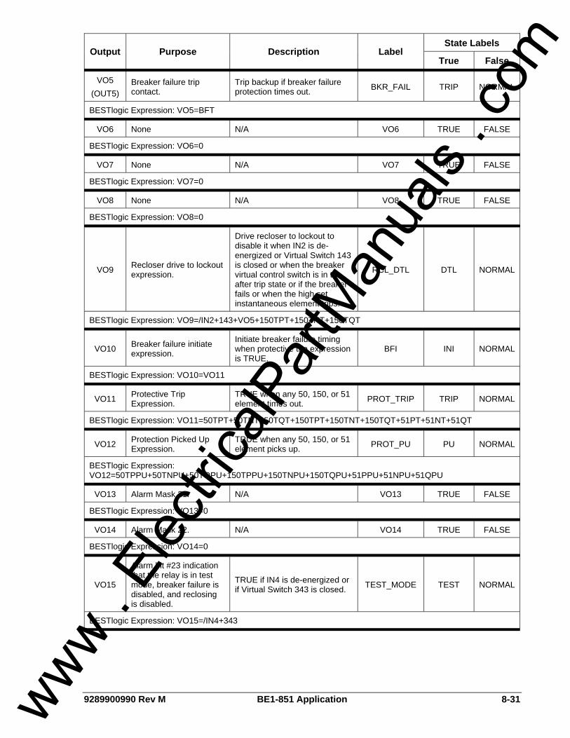
9289900990 Rev M BE1-851 Application 8-31
State Labels Output Purpose Description Label
True False
VO5 (OUT5)
Breaker failure trip contact.
Trip backup if breaker failure protection times out. BKR_FAIL TRIP NORMAL
BESTlogic Expression: VO5=BFT
VO6 None N/A VO6 TRUE FALSE
BESTlogic Expression: VO6=0
VO7 None N/A VO7 TRUE FALSE
BESTlogic Expression: VO7=0
VO8 None N/A VO8 TRUE FALSE
BESTlogic Expression: VO8=0
VO9 Recloser drive to lockout expression.
Drive recloser to lockout to disable it when IN2 is de-energized or Virtual Switch 143 is closed or when the breaker virtual control switch is in the after trip state or if the breaker fails or when the high set instantaneous element trips.
RCL_DTL DTL NORMAL
BESTlogic Expression: VO9=/IN2+143+VO5+150TPT+150TNT+150TQT
VO10 Breaker failure initiate expression.
Initiate breaker failure timing when protective trip expression is TRUE.
BFI INI NORMAL
BESTlogic Expression: VO10=VO11
VO11 Protective Trip Expression.
TRUE when any 50, 150, or 51 element times out. PROT_TRIP TRIP NORMAL
BESTlogic Expression: VO11=50TPT+50TNT+50TQT+150TPT+150TNT+150TQT+51PT+51NT+51QT
VO12 Protection Picked Up Expression.
TRUE when any 50, 150, or 51 element picks up. PROT_PU PU NORMAL
BESTlogic Expression: VO12=50TPPU+50TNPU+50TQPU+150TPPU+150TNPU+150TQPU+51PPU+51NPU+51QPU
VO13 Alarm Mask 21. N/A VO13 TRUE FALSE
BESTlogic Expression: VO13=0
VO14 Alarm Mask 22. N/A VO14 TRUE FALSE
BESTlogic Expression: VO14=0
VO15
Alarm bit #23 indication that the relay is in test mode, breaker failure is disabled, and reclosing is disabled.
TRUE if IN4 is de-energized or if Virtual Switch 343 is closed. TEST_MODE TEST NORMAL
BESTlogic Expression: VO15=/IN4+343
www . El
ectric
alPar
tMan
uals
. com
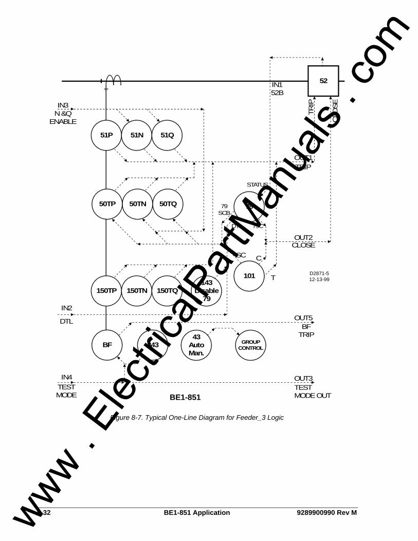
8-32 BE1-851 Application 9289900990 Rev M
52
CLO
SE
51P 51N 51Q
D2871-512-13-99
OUT1
TRIP
TRIP
79
T
C
101
79C
IN3N &Q
ENABLE
79SCB
50TQ50TN50TP
BE1-851
OUT3
GROUPCONTROL
43AutoMan.
343
OUT5
BF
BFTRIP
IN4TESTMODE
TESTMODE OUT
150TP 150TN 150TQ
DTL
OUT2CLOSE
143Disable
79IN2
DTL
STATUS
IN152B
SC
Figure 8-7. Typical One-Line Diagram for Feeder_3 Logic
www . El
ectric
alPar
tMan
uals
. com
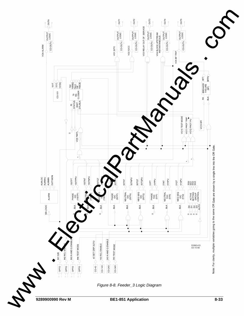
9289900990 Rev M BE1-851 Application 8-33
Figure 8-8. Feeder_3 Logic Diagram
www . El
ectric
alPar
tMan
uals
. com
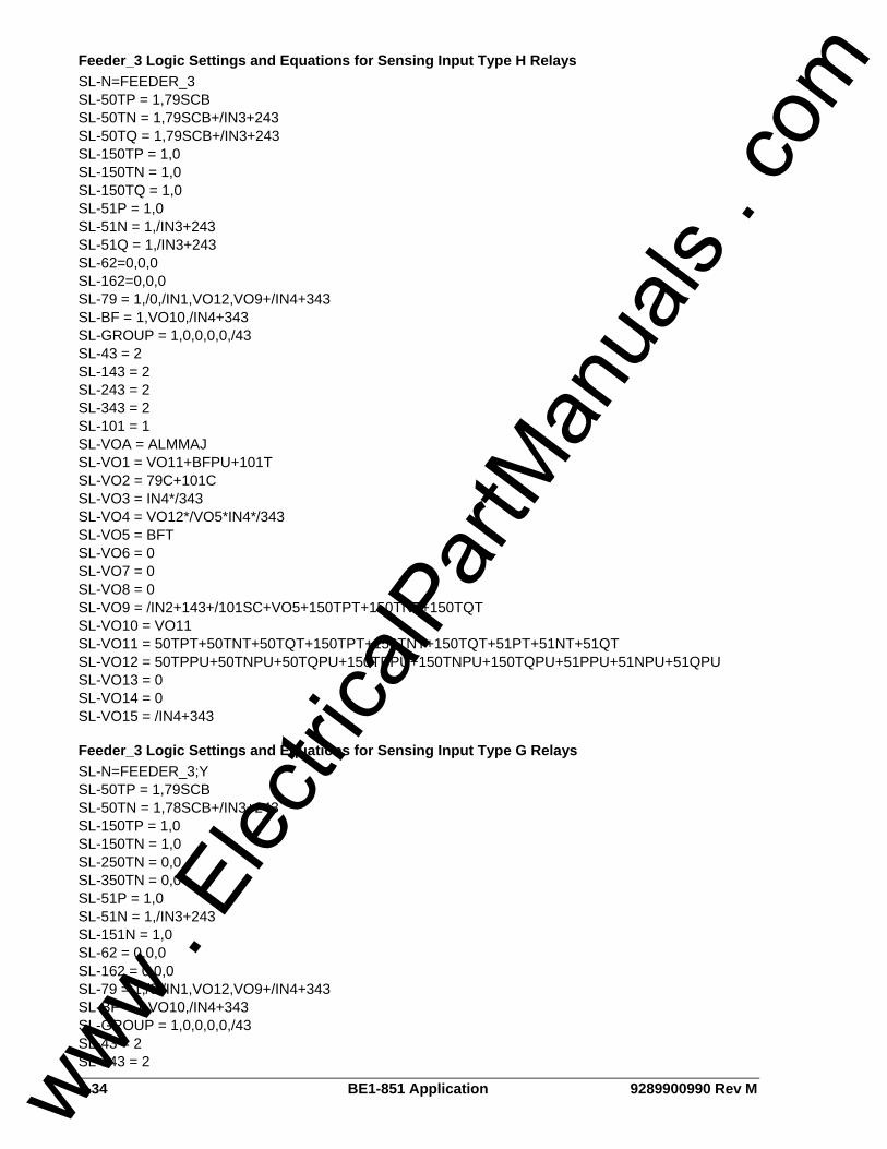
8-34 BE1-851 Application 9289900990 Rev M
Feeder_3 Logic Settings and Equations for Sensing Input Type H Relays SL-N=FEEDER_3 SL-50TP = 1,79SCB SL-50TN = 1,79SCB+/IN3+243 SL-50TQ = 1,79SCB+/IN3+243 SL-150TP = 1,0 SL-150TN = 1,0 SL-150TQ = 1,0 SL-51P = 1,0 SL-51N = 1,/IN3+243 SL-51Q = 1,/IN3+243 SL-62=0,0,0 SL-162=0,0,0 SL-79 = 1,/0,/IN1,VO12,VO9+/IN4+343 SL-BF = 1,VO10,/IN4+343 SL-GROUP = 1,0,0,0,0,/43 SL-43 = 2 SL-143 = 2 SL-243 = 2 SL-343 = 2 SL-101 = 1 SL-VOA = ALMMAJ SL-VO1 = VO11+BFPU+101T SL-VO2 = 79C+101C SL-VO3 = IN4*/343 SL-VO4 = VO12*/VO5*IN4*/343 SL-VO5 = BFT SL-VO6 = 0 SL-VO7 = 0 SL-VO8 = 0 SL-VO9 = /IN2+143+/101SC+VO5+150TPT+150TNT+150TQT SL-VO10 = VO11 SL-VO11 = 50TPT+50TNT+50TQT+150TPT+150TNT+150TQT+51PT+51NT+51QT SL-VO12 = 50TPPU+50TNPU+50TQPU+150TPPU+150TNPU+150TQPU+51PPU+51NPU+51QPU SL-VO13 = 0 SL-VO14 = 0 SL-VO15 = /IN4+343
Feeder_3 Logic Settings and Equations for Sensing Input Type G Relays SL-N=FEEDER_3;Y SL-50TP = 1,79SCB SL-50TN = 1,78SCB+/IN3+243 SL-150TP = 1,0 SL-150TN = 1,0 SL-250TN = 0,0 SL-350TN = 0,0 SL-51P = 1,0 SL-51N = 1,/IN3+243 SL-151N = 1,0 SL-62 = 0,0,0 SL-162 = 0,0,0 SL-79 = 1,/0,/IN1,VO12,VO9+/IN4+343 SL-BF = 1,VO10,/IN4+343 SL-GROUP = 1,0,0,0,0,/43 SL-43 = 2 SL-143 = 2
www . El
ectric
alPar
tMan
uals
. com

9289900990 Rev M BE1-851 Application 8-35
SL-243 = 2 SL-343 = 2 SL-101 = 1 SL-VOA = ALMMAJ SL-VO1 = VO11+BFPU+101T SL-VO2 = 79C+101C SL-VO3 = IN4*/343 SL-VO4 = VO12*/VO5*IN4*/343 SL-VO5 = BFT SL-VO6 = 0 SL-VO7 = 0 SL-VO8 = 0 SL-VO9 = /IN2+143+/101SC+VO5+150TPT+150TNT SL-VO10 = VO11 SL-VO11 = 50TPT+50TNT+150TPT+150TNT+51PT+51NT SL-VO12 = 50TPPU+50TNPU+150TPPU+150TNPU+51PPU+51NPU SL-VO13 = 0 SL-VO14 = 0 SL-VO15 = /IN4+343
FEEDER_4 LOGIC SCHEME Logic scheme Feeder_4 is meant for use on a feeder breaker and provides all overcurrent and breaker failure protection, reclosing, and control functions required for a typical feeder in a non-directional overcurrent protection application. This logic is intended for use in conjunction with redundant protective relays such as existing electromechanical relays to provide backup when the relay is out of service. Automatic reclosing is initiated by the breaker opening. Reclosing is disabled after a manual trip by a control switch slip contact. In this logic scheme, the disable logic is connected to the reclose initiate (RI) input. Once re-enabled, the recloser will start the sequence and automatically close the breaker if it is open. When used in conjunction with other programmable relays using logic scheme BUS, it can provide complete overcurrent protection for the transformers, bus, and feeders in a radial system substation. The components of Feeder_4 logic are summarized in Tables 8-17 through 8-20. Figure 8-9 is a one-line diagram of Feeder_4 logic and Figure 8-10 is a diagram representing the logic settings and equations of Feeder_4 logic.
Normal Operation - Control The virtual breaker control switch is programmed to provide manual trip and close control of the breaker. The control functions of this logic scheme use both traditional contact sensing inputs and virtual switches. Virtual switches that are not needed may simply go unused. The protection engineer may choose to free up contact sensing inputs for other uses by using the virtual switches exclusively for the various control functions.
Normal Operation - Protection The 50T and 51 function blocks and the breaker failure function block re-trip output are enabled in Feeder_4 logic for tripping via OUT1. Setting the pickup at zero in the four setting groups can individually disable each overcurrent function block. The 50TN, 50TQ, 51N, and 51Q function blocks are torque controlled by Virtual Switch 243. All N and Q function blocks or only the 51N and 51Q function blocks may be inhibited. This is done in BESTlogic by modifying the inputs to the function blocks.
Normal Operation - Reclosing The reclosing logic in Feeder_4 is initiated by the breaker opening. Automatic reclosing is disabled for a manual trip by a control switch slip contact. Setting the first reclose time = zero can disable the recloser function block in the four setting groups. Reclosing can be disabled by IN2 or Virtual Switch 143 that interrupts the RI input to the recloser function block. In this scheme, enabling the recloser after a “one shot” trip will cause the recloser to start the
www . El
ectric
alPar
tMan
uals
. com

8-36 BE1-851 Application 9289900990 Rev M
reclosing sequence and automatically close the breaker. If the control switch slip contact is in the after trip position, the recloser will not automatically start. If an external control switch slip contact is used, it should be wired in series with the reclose enable switch to IN2. The BESTlogic can be modified so that the reclosing disable logic drives the recloser to lockout instead of interrupting the RI input. This is accomplished by using variables IN2, 143, and 101SC in the DTL expression instead of the RI expression. This recloser control logic is used in preprogrammed logic scheme Feeder_3. The recloser will be driven to lockout if a breaker failure occurs. Setting an appropriate logic expression for 79ZONE can enable zone-sequence coordination. Zone-sequence uses a BESTlogic expression but is not within the logic settings. The Feeder_4 logic scheme uses the expression SP-79ZONE=VO12. Feeder_4 logic provides for the recloser to torque control the 50TP/N/Q functions (typically used for low set instantaneous protection) during various steps in the reclosing sequence. Setting the recloser sequence controlled blocking output in the four setting groups is done using the S#-79SCB command. Blocking of external instantaneous elements is done through OUT3. Recloser timing is stopped by the wait input if an overcurrent protection function block is picked up and timing. This prevents the reset timer from resetting the reclose function for a situation where a 51 element is just above pickup and the time to trip is longer than the reset time. A block load tap changer output is not provided in this scheme. OUT5 can be reprogrammed as a 79RNG (recloser running/block tap changer) output and wired to energize a normally closed auxiliary relay.
Normal Operation - Bus Protection When any of the 50T or 51 function blocks is picked up, OUT4 closes. The signal from OUT4 is wired to IN2 of the upstream relay using BUS logic. The upstream relay blocks the 150T elements that are set up to trip the bus breaker or bus lockout relay. If the fault is not on a feeder, the 150T elements of the bus relay are not blocked. The bus relay 150T elements are set with a time delay of 2 to 20 cycles to provide a coordination interval for the feeder relay OUT4 to close or the redundant feeder relays to trip the feeder breaker. Should there be a problem with the blocking logic, the bus relay 51 functions are not blocked to allow bus fault clearing with a traditional coordination interval. When used to provide high-speed overcurrent protection for the substation bus, it is recommended that all 51 function timing curves be set for instantaneous reset. Use of this protection feature with redundant electromechanical relays should be done with caution. Retrofit of the electromechanical relays with BE1-50/51B solid-state overcurrent relays can mitigate this concern.
Normal Operation - Alarms Two alarm logic variables drive the front panel alarm LEDs: Major alarm (ALMMAJ) and Minor alarm (ALMMIN). ALMMAJ is set to drive the fail-safe output OUTA. ALMMIN is not set to drive an output relay. The logic can be modified to place ALMMIN in the BESTlogic expression for VOA if all alarms are to be combined. ALMMIN can be placed in the BESTlogic expression for another output if it is desired that these conditions be enunciated separately.
Contingency Operation - Test Mode The test mode is intended to increase the security of the feeder protection and control system if external test switches are not installed on all outputs. When the relay is out of service for testing, the breaker failure, automatic reclosing, and block upstream instantaneous functions are disabled. Backup by the upstream relay is enabled. De-energizing IN4 or closing Virtual Switch 343 will put the logic in test mode. IN4 can be controlled by a panel mounted selector switch that is closed in the normal state and open in the test state. IN4 can also be controlled by a standard external test switch that is opened with the rest of the test switch poles. The logic expression for test mode drives virtual output 15 (VO15). This virtual output is alarm bit #23 in the programmable alarm mask. It can be masked to drive an alarm LED to provide indication when the relay is in Test Mode.
www . El
ectric
alPar
tMan
uals
. com

9289900990 Rev M BE1-851 Application 8-37
Contingency Operation - Backup Protection for Feeder Breaker Failure OUT5 is configured as the breaker failure trip output. OUT5 can be wired to trip the bus breaker or a lockout relay. The breaker failure pickup (BFPU) output trips the feeder breaker directly via output 1 to provide a breaker re-trip signal for added security. Initiation of the BF function block by external relays is provided by IN3. The 150T function blocks provide fault detector supervision of the external initiate signal. The logic uses the pickup outputs of the function blocks. In this application, the time delay settings should be set to maximum so that they do not time out and trip targets. If the external BFI signal from protective relays such as 81 or 87T where fault detector supervision is not desired, the BESTlogic expression for VO12 which is the BFI logic expression in this logic scheme, can be modified. The BF function block is also initiated by a protective trip. This function block has an independent fast drop out phase and ground current detector that detects a breaker opening and stops timing. An open breaker is detected when the current drops below 10% of nominal. Setting the time delay at zero disables the BF function block. This permits the traditional radial system backup scheme of coordinated relays tripping different breakers. Feeder_4 logic stops the block signal to allow the bus relay to trip the bus breaker through its 50T elements if a direct trip is not desired. This provides clearing of the fault on the circuit with the failed breaker in feeder relay breaker failure time (or bus relay 50T time; whichever is greater) instead of the bus relay 51 time but is limited by the sensitivity constraints of the bus relay.
Contingency Operation - Backup Protection for Feeder Relay Out-of-Service Primary protection for relay failure is provided by redundant relays applied to the feeder.
Table 8-17. Feeder_4 Contact Sensing Input Logic
State Labels Input Purpose Name Label
Energized De-Energized
IN1 52b Breaker Status. BREAKER OPEN CLOSED
IN2 Enable recloser when IN2 is energized. RCL_ENABLE ENABLED DISABLD
IN3 Enable neutral and negative-sequence, 50 and 51 protection when IN3 is energized.
N&Q_ENABLE ENABLED DISABLD
IN4 Put the relay in test mode so that reclosing and breaker failure are disabled when IN4 is de-energized.
TESTDISABL NORMAL TSTMODE
Table 8-18. Feeder_4 Function Block Logic
Function Purpose BESTlogic Expression
Mode Setting
50TP Used for instantaneous phase overcurrent protection. Block when recloser sequence controlled blocking output is TRUE.
79SCB 1 (enabled)
50TN
Used for instantaneous neutral overcurrent protection. Block when recloser sequence controlled blocking output is TRUE or when disabled by Virtual Switch 243.
79SCB+243 1 (enabled)
www . El
ectric
alPar
tMan
uals
. com

8-38 BE1-851 Application 9289900990 Rev M
Function Purpose BESTlogic Expression
Mode Setting
50TQ
Used for instantaneous negative-sequence overcurrent protection. Block when recloser sequence controlled blocking output is TRUE or when disabled by Virtual Switch 243.
79SCB+243 1 (enabled)
150TP Used for instantaneous phase overcurrent protection. 0 1 (enabled)
150TN Used for instantaneous neutral overcurrent protection. 0 1 (enabled)
150TQ Used for instantaneous negative-sequence overcurrent protection. 0 1 (enabled)
51P Used for timed phase overcurrent protection. 0 1 (enabled)
51N Used for timed neutral overcurrent protection. Block when disabled by Virtual Switch 243. 243 1 (enabled)
51Q Used for timed negative-sequence overcurrent protection. Block when disabled by Virtual Switch 243. 243 1 (enabled)
62 N/A 0 0 (disabled)
162 N/A 0 0 (disabled)
RI Logic: Initiate when reclose initiate expression is TRUE VO8
STATUS Logic: Breaker closed when IN1 is de-energized. /IN1
WAIT Logic: Stop recloser timing when timing for a fault trip. TRUE when protection picked up expression is TRUE.
VO12 79
BLK/DTL Logic: Drive recloser to lockout when recloser drive to lockout expression is TRUE or when relay is in test mode.
VO9+/IN4+343
1 (Power Up to Lockout)
Initiate breaker failure when breaker failure initiate expression is TRUE. VO10
BF Block breaker failure protection when relay is in test mode. /IN4+343
1 (enabled)
No manual selection logic is used. 0
No manual selection logic is used. 0
No manual selection logic is used. 0
No manual selection logic is used. 0 GROUP
Disable automatic selection when Virtual Switch 43 is in the manual position. /43
1 (Discrete Inputs)
www . El
ectric
alPar
tMan
uals
. com
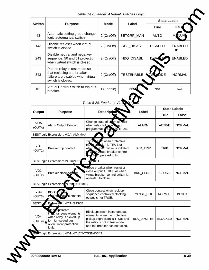
9289900990 Rev M BE1-851 Application 8-39
Table 8-19. Feeder_4 Virtual Switches Logic
State Labels Switch Purpose Mode Label
True False
43 Automatic setting group change logic auto/manual switch. 2 (On/Off) SETGRP_MAN AUTO MANUAL
143 Disable recloser when virtual switch is closed. 2 (On/Off) RCL_DISABL DISABLD ENABLED
243 Disable neutral and negative-sequence, 50 and 51 protection when virtual switch is closed.
2 (On/Off) N&Q_DISABL DISABLD ENABLED
343
Put the relay in test mode so that reclosing and breaker failure are disabled when virtual switch is closed.
2 (On/Off) TESTENABLE TSTMODE NORMAL
101 Virtual Control Switch to trip bus breaker. 1 (Enable) N/A N/A N/A
Table 8-20. Feeder_4 Virtual Outputs
State Labels Output Purpose Description Label
True False
VOA (OUTA)
Alarm Output Contact. Change state of alarm contact when relay failure or major programmable alarm is TRUE.
ALARM ACTIVE NORMAL
BESTlogic Expression: VOA=ALMMAJ
VO1 (OUT1)
Breaker trip contact.
Trip breaker when protective trip expression is TRUE or when breaker failure is initiated or when virtual breaker control switch is operated to trip
BKR_TRIP TRIP NORMAL
BESTlogic Expression: VO1=VO11+BFPU+101T
VO2 (OUT2)
Breaker close contact.
Close breaker when recloser close output it TRUE or when virtual breaker control switch is operated to close.
BKR_CLOSE CLOSE NORMAL
BESTlogic Expression: VO2=79C+101C
VO3 (OUT3)
Block external instantaneous elements.
Close contact when recloser sequence controlled blocking output is not TRUE.
79INST_BLK NORMAL BLOCK
BESTlogic Expression: VO3=/79SCB
VO4 (OUT4)
Block upstream instantaneous elements when relay is picked up for high-speed bus overcurrent protection logic.
Block upstream instantaneous elements when the protective pickup expression is TRUE and the relay is not in test mode and the breaker has not failed.
BLK_UPSTRM BLOCKED NORMAL
BESTlogic Expression: VO4=VO12*/VO5*IN4*/343
www . El
ectric
alPar
tMan
uals
. com
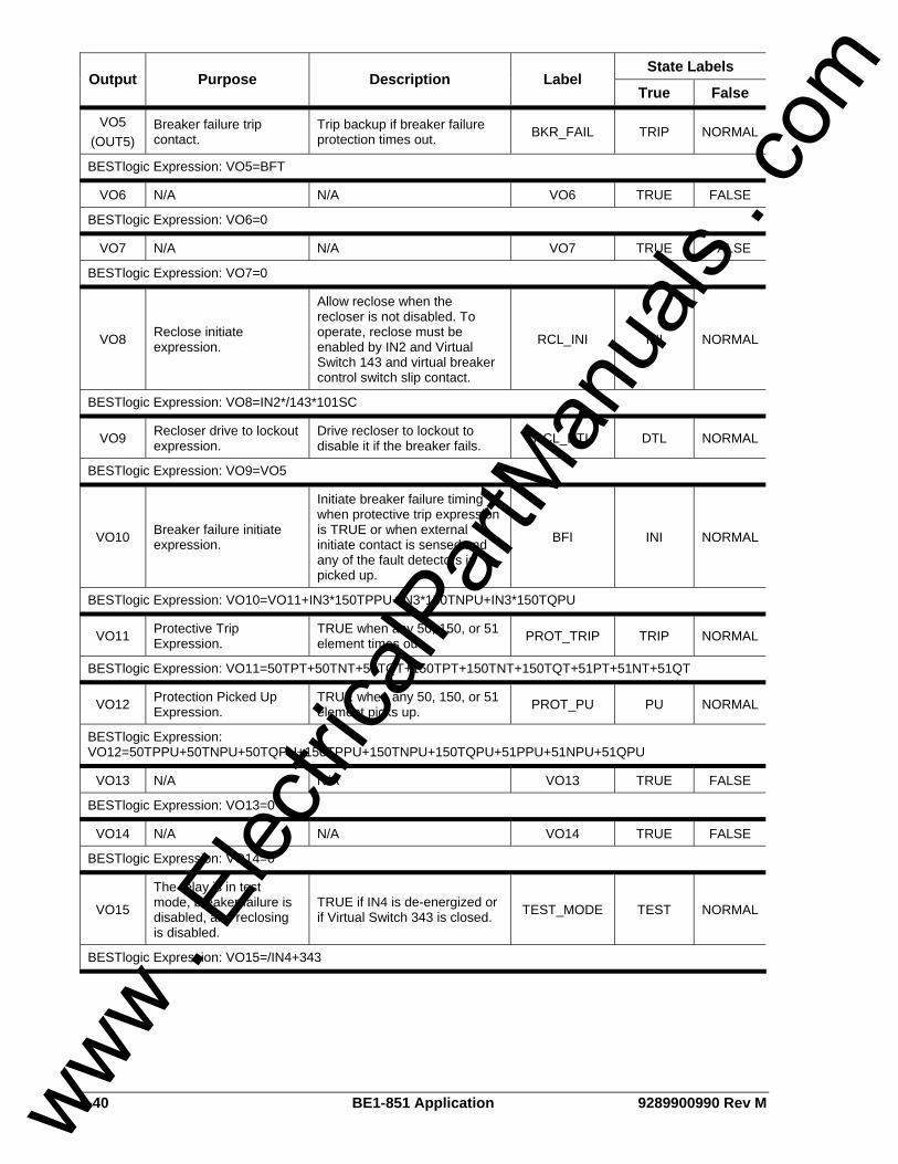
8-40 BE1-851 Application 9289900990 Rev M
State Labels Output Purpose Description Label
True False
VO5 (OUT5)
Breaker failure trip contact.
Trip backup if breaker failure protection times out. BKR_FAIL TRIP NORMAL
BESTlogic Expression: VO5=BFT
VO6 N/A N/A VO6 TRUE FALSE
BESTlogic Expression: VO6=0
VO7 N/A N/A VO7 TRUE FALSE
BESTlogic Expression: VO7=0
VO8 Reclose initiate expression.
Allow reclose when the recloser is not disabled. To operate, reclose must be enabled by IN2 and Virtual Switch 143 and virtual breaker control switch slip contact.
RCL_INI INI NORMAL
BESTlogic Expression: VO8=IN2*/143*101SC
VO9 Recloser drive to lockout expression.
Drive recloser to lockout to disable it if the breaker fails. RCL_DTL DTL NORMAL
BESTlogic Expression: VO9=VO5
VO10 Breaker failure initiate expression.
Initiate breaker failure timing when protective trip expression is TRUE or when external initiate contact is sensed and any of the fault detectors is picked up.
BFI INI NORMAL
BESTlogic Expression: VO10=VO11+IN3*150TPPU+IN3*150TNPU+IN3*150TQPU
VO11 Protective Trip Expression.
TRUE when any 50, 150, or 51 element times out. PROT_TRIP TRIP NORMAL
BESTlogic Expression: VO11=50TPT+50TNT+50TQT+150TPT+150TNT+150TQT+51PT+51NT+51QT
VO12 Protection Picked Up Expression.
TRUE when any 50, 150, or 51 element picks up. PROT_PU PU NORMAL
BESTlogic Expression: VO12=50TPPU+50TNPU+50TQPU+150TPPU+150TNPU+150TQPU+51PPU+51NPU+51QPU
VO13 N/A N/A VO13 TRUE FALSE
BESTlogic Expression: VO13=0
VO14 N/A N/A VO14 TRUE FALSE
BESTlogic Expression: VO14=0
VO15
The relay is in test mode, breaker failure is disabled, and reclosing is disabled.
TRUE if IN4 is de-energized or if Virtual Switch 343 is closed. TEST_MODE TEST NORMAL
BESTlogic Expression: VO15=/IN4+343
www . El
ectric
alPar
tMan
uals
. com
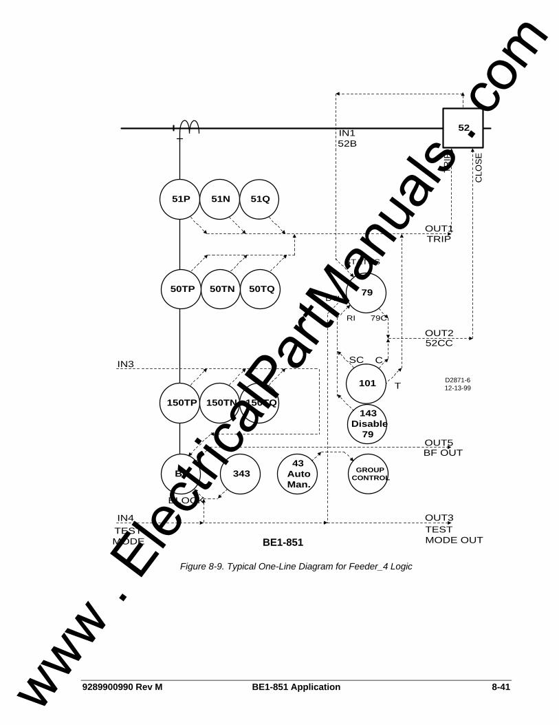
9289900990 Rev M BE1-851 Application 8-41
52
CLO
SE
51P 51N 51Q
D2871-612-13-99
OUT1
TRIP
TRIP
79
T
C
101
79C
STATUS
50TQ50TN50TP
BE1-851
OUT3
GROUPCONTROL
43AutoMan.
343
OUT5
BF
BF OUT
TESTMODE OUT
150TP 150TN 150TQ
RI
OUT252CC
143Disable
79
SCIN3
IN152B
DTL
IN4TESTMODE
BLOCK
Figure 8-9. Typical One-Line Diagram for Feeder_4 Logic
www . El
ectric
alPar
tMan
uals
. com
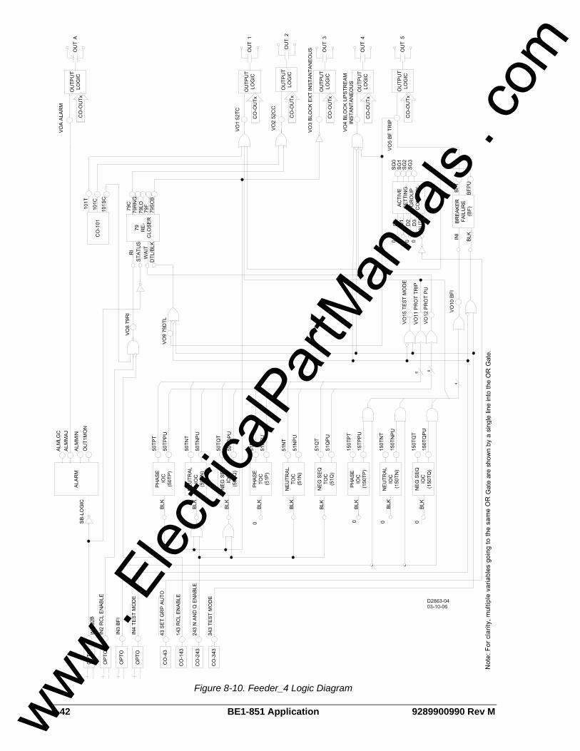
8-42 BE1-851 Application 9289900990 Rev M
Figure 8-10. Feeder_4 Logic Diagram
www . El
ectric
alPar
tMan
uals
. com
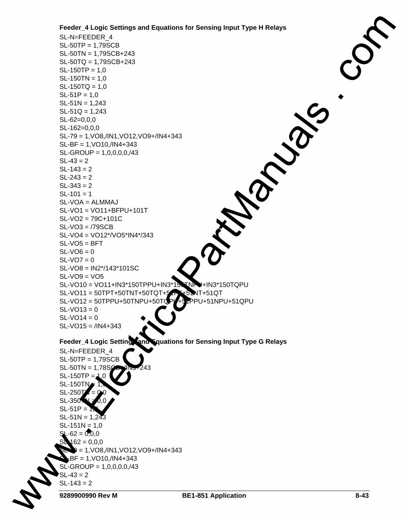
9289900990 Rev M BE1-851 Application 8-43
Feeder_4 Logic Settings and Equations for Sensing Input Type H Relays SL-N=FEEDER_4 SL-50TP = 1,79SCB SL-50TN = 1,79SCB+243 SL-50TQ = 1,79SCB+243 SL-150TP = 1,0 SL-150TN = 1,0 SL-150TQ = 1,0 SL-51P = 1,0 SL-51N = 1,243 SL-51Q = 1,243 SL-62=0,0,0 SL-162=0,0,0 SL-79 = 1,VO8,/IN1,VO12,VO9+/IN4+343 SL-BF = 1,VO10,/IN4+343 SL-GROUP = 1,0,0,0,0,/43 SL-43 = 2 SL-143 = 2 SL-243 = 2 SL-343 = 2 SL-101 = 1 SL-VOA = ALMMAJ SL-VO1 = VO11+BFPU+101T SL-VO2 = 79C+101C SL-VO3 = /79SCB SL-VO4 = VO12*/VO5*IN4*/343 SL-VO5 = BFT SL-VO6 = 0 SL-VO7 = 0 SL-VO8 = IN2*/143*101SC SL-VO9 = VO5 SL-VO10 = VO11+IN3*150TPPU+IN3*150TNPU+IN3*150TQPU SL-VO11 = 50TPT+50TNT+50TQT+51PT+51NT+51QT SL-VO12 = 50TPPU+50TNPU+50TQPU+51PPU+51NPU+51QPU SL-VO13 = 0 SL-VO14 = 0 SL-VO15 = /IN4+343
Feeder_4 Logic Settings and Equations for Sensing Input Type G Relays SL-N=FEEDER_4 SL-50TP = 1,79SCB SL-50TN = 1,78SCB+/IN3+243 SL-150TP = 1,0 SL-150TN = 1,0 SL-250TN = 0,0 SL-350TN = 0,0 SL-51P = 1,0 SL-51N = 1,243 SL-151N = 1,0 SL-62 = 0,0,0 SL-162 = 0,0,0 SL-79 = 1,VO8,/IN1,VO12,VO9+/IN4+343 SL-BF = 1,VO10,/IN4+343 SL-GROUP = 1,0,0,0,0,/43 SL-43 = 2 SL-143 = 2
www . El
ectric
alPar
tMan
uals
. com

8-44 BE1-851 Application 9289900990 Rev M
SL-243 = 2 SL-343 = 2 SL-101 = 1 SL-VOA = ALMMAJ SL-VO1 = VO11+BFPU+101T SL-VO2 = 79C+101C SL-VO3 = /79SCB SL-VO4 = VO12*/VO5*IN4*/343 SL-VO5 = BFT SL-VO6 = 0 SL-VO7 = 0 SL-VO8 = IN2*/143*101SC SL-VO9 = VO5 SL-VO10 = VO11+IN3*150TPPU+IN3*150TNPU SL-VO11 = 50TPT+50TNT+51PT+51NT SL-VO12 = 50TPPU+50TNPU+51PPU+51NPU SL-VO13 = 0 SL-VO14 = 0 SL-VO15 = /IN4+343
BUS AND BACKUP LOGIC SCHEMES Logic schemes BUS and BACKUP are meant for use on a bus main breaker, and provide all overcurrent protection and control functions required for a typical bus main breaker in a non-directional overcurrent protection application. These logic schemes are intended for use in conjunction with other programmable relays using the Feeder_1, Feeder_2, and Feeder_3 logic schemes to provide complete overcurrent protection for the transformers, bus, and feeders in a radial system substation. The components of BUS logic are summarized in Tables 8-21 through 8-24. Figure 8-11 is a one-line diagram of BUS logic and Figure 8-12 is a diagram representing the logic settings and equations of BUS logic. The components of BACKUP logic are summarized in Tables 8-25 through 8-28. Figure 8-13 is a one-line diagram of BACKUP logic and Figure 8-14 is a diagram representing the logic settings and equations of BACKUP logic. When interconnected with feeder relays using logic scheme Feeder_1, Feeder_2, or Feeder_3, the BACKUP logic scheme provides complete backup (except for reclosing) for the feeder relays if relay failure occurs or when they are out of service for testing or maintenance. Figure 8-15 shows the interconnection of Feeder, BUS, and BACKUP relays to achieve this integrated protection system.
Normal Operation - Control The virtual breaker control switch is programmed to provide manual trip and close control of the bus breaker in both BUS and BACKUP logic. The control functions of these logic schemes use both traditional contact sensing inputs and virtual switches. Virtual switches that are not needed may simply go unused. The protection engineer may choose to free up contact sensing inputs for other uses by using the virtual switches exclusively for the various control functions.
Normal Operation - Bus Protection The BUS relay logic primary task in normal operation is to provide high-speed bus fault protection (2-4 cycles coordination interval) and timed overload or high unbalanced load protection. The BACKUP relay logic primary task is to backup the Bus relay for bus faults with a coordination interval of 18-20 cycles When any of the feeder relay overcurrent elements are picked up and timing, OUT4 on the feeder relay closes. This signal is wired to IN2 of the upstream (primary) bus relay using Bus logic that blocks the 50T elements. These are set with a delay of 2 to 4 cycles. If the fault is not on a feeder, the 50T elements of the bus relays are not blocked. The 50T function blocks are set up to trip the bus breaker by an external bus lockout relay (86B) via OUT4. The BACKUP relay does not get blocked when the feeder relays are picked up so its 50T elements are set with a time delay long enough to allow the feeder breaker to interrupt the fault. These are set up to trip the 86B relay also via OUT4. If a bus fault lockout relay is not used, OUT4 can be wired in parallel with OUT1 to direct trip the bus breaker.
www . El
ectric
alPar
tMan
uals
. com

9289900990 Rev M BE1-851 Application 8-45
The BUS and BACKUP 50T functions should be set with a higher pickup that the highest feeder instantaneous elements to ensure that they will not pickup before any feeder relay. If there is a contingency problem such as a relay removed from service, 51 protection is still provided. The BUS and BACKUP 51 functions are enabled for tripping via OUT1. The 51 functions are not blocked to allow clearing a bus fault with a traditional coordination interval. When used to provide high-speed overcurrent protection for the substation bus, it is recommended that all 51 function timing curves be set for instantaneous reset.
Normal Operation - Setting Group Selection For normal operation, the BUS and BACKUP relays are in setting group 0. In setting group 0, the two relays will only trip the bus breaker. Input 2 to the BACKUP relay identifies when a feeder relay is out of service. The BACKUP relay then closes OUT3 that is connected to input 3 of the BUS relay. The two relays then switch to setting group 1. Setting group selection mode 2, binary coded selection, is used to recognize the group setting state. When input D0 to the setting group selection function block is a 1, it is interpreted as a binary 1 causing the logic to switch to group 1. When the relay is in setting group 1, the relays are operating in feeder relay backup mode. This expression is programmed to virtual output 13 of the BUS relay that drives alarm bit #21 in the programmable alarm mask. It can be masked to drive an alarm LED and alarm display to indicate when the BUS relay is in feeder backup mode and to trip a feeder breaker instead of the bus breaker.
Normal Operation - Alarms Two alarm logic variables drive the front panel alarm LEDs: Major alarm (ALMMAJ) and Minor alarm (ALMMIN). ALMMAJ is set to drive the fail-safe output OUTA. ALMMIN is not set to drive an output relay. The logic can be modified to place ALMMIN in the BESTlogic expression for VOA if all alarms are to be combined. ALMMIN can be placed in the BESTlogic expression for another output if it is desired that these conditions be enunciated separately.
Contingency Operation - Test Mode The test mode is intended to increase the security of the protection and control system if external test switches are not installed on all outputs. When the BUS relay is out of service for testing, the overcurrent protection function trip outputs are routed to OUT1 only. When the BACKUP relay is out of service for testing, the overcurrent protection function trip outputs are routed to OUT1 only and the breaker failure function is disabled. De-energizing IN4 or closing Virtual Switch 343 will put the logic in test mode. IN4 can be controlled by a panel mounted selector switch that is closed in the normal state and open in the test state. IN4 can also be controlled by a pole of a standard external test switch that is opened with the rest of the test switch poles. The logic expression for test mode drives virtual output 15 (VO15). This virtual output is alarm bit #23 in the programmable alarm mask. It can be masked to drive an alarm LED and HMI alarm display to provide indication when the relay is in test mode.
Contingency Operation - Backup Protection for Bus Breaker Failure Bus breaker failure protection is provided by the main bus relay using preprogrammed logic scheme BACKUP. OUT5 is configured as the breaker failure trip output. OUT5 can be wired to trip the upstream breaker or a bus breaker failure lockout relay or other lockout relay that trips the transformer high side such as the 86T transformer differential lockout relay. Initiation of the BF function block by external relays is provided by IN3. The 150T function blocks provide fault detector supervision of the external initiate signal. The logic uses the pickup outputs of the function blocks. In this application, the time delay settings should be set to maximum so that they do not time out and trip targets. If the external BFI signal from protective relays such as 81 or 87T where fault detector supervision is not desired, the BESTlogic expression for VO12 which is the BFI logic expression in this logic scheme, can be modified. The BF function block is also initiated by a protective trip. If you are tripping for a bus fault via a lockout relay, the additional time delay of the lockout relay should be added to your breaker failure time setting. This function block has an independent fast drop out phase and ground current detector that detects a breaker opening and stops timing. An open breaker is detected when the current drops below 10% of nominal.
www . El
ectric
alPar
tMan
uals
. com

8-46 BE1-851 Application 9289900990 Rev M
Setting the time delay at zero disables the BF function block. This permits the traditional radial system backup scheme of coordinated relays tripping different breakers.
Contingency Operation - Backup Protection for BUS Relay Out-of-Service When the BUS relay is out of service, backup protection is provided by the BACKUP main bus relay. The BACKUP main bus relay provides permanent backup protection for the BUS relay regardless of other feeder contingencies. Under this contingency, protection for bus faults will be delayed by an 18-20 cycle coordination interval.
Contingency Operation - Backup Protection for BACKUP Relay Out-of-Service When the BACKUP relay is out of service, full high-speed bus fault protection and overload protection are provided by the BUS relay. Under this contingency, bus breaker failure protection is not provided, as this is a double contingency situation.
Contingency Operation - Backup Protection for Feeder Relay Out-of-Service OUT3 of each of the feeder relays should be wired to an auxiliary transfer relay (83/Fn) with one normally open and one normally closed contact. Under normal conditions, OUT3 of the feeder relay is closed and the 83 aux. Relay is picked up. When the feeder relay is out of service due to failure, being in test mode, or if it is drawn out from its case, the 83 auxiliary relay will drop out. The normally open contact (NO in shelf state) of the 83/Fn aux. relay is wired to Input 2 of the BACKUP relay to signal the BUS and BACKUP relays to change to setting group 1. When the BUS relay is in setting group 1, the 50T and 51 overcurrent function blocks trip an auxiliary tripping relay (94/BU) via OUT5. In setting group 1, the BACKUP relay 51 time settings must coordinate with the BUS relay 51 time dial settings. Since the feeder relays provide a blocking signal to the BUS relay upon pickup of the 51 function blocks, it is not necessary for the 51 time dial settings on the BUS relay to coordinate with the feeder relays in setting group 1. Therefore, the 51 time dial settings of the BUS relay can be reduced in setting group 1 to provide the necessary coordination interval between the BUS relay and the BACKUP relay for this contingency. This minimizes the time delay that needs to be added to the 51 time dial settings for the BACKUP relay and provides a greater opportunity to keep the setting below the transformer damage curve. The tripping output of the 94/BU auxiliary relay and the normally closed contacts (form B) of the 83/Fn auxiliary relay are wired in series with the feeder breaker trip coil. This allows the 94/BU relay to trip the feeder breaker when the feeder relay is out of service. When the BUS and BACKUP relays are in feeder relay backup mode, operation for the various faults is as follows:
• A fault on a feeder with its relay still in service will send a blocking signal to the BUS relay preventing it from tripping high-speed. The 51 functions of the BUS and BACKUP relays are set to coordinate with each other and the feeder relays.
• A fault on the feeder with the relay out of service will not send a blocking signal to the BUS relay so it will trip the feeder breaker via the 94 and 83 relay contacts. Fault clearing will be after the 2 to 4 cycle coordination interval set on the BUS relay 50T functions or in BUS relay 51 time if the fault is farther out. For this reason, the BACKUP relay 51 functions must be set to coordinate with the BUS relay in this setting group.
• A fault on the bus will cause the BUS relay to trip the feeder breaker with the relay out of service because no blocking signal will be sent by any of the feeder relays. Since this will not clear the fault, the BACKUP relay will clear the fault with its 18-20 cycle coordination interval.
www . El
ectric
alPar
tMan
uals
. com

9289900990 Rev M BE1-851 Application 8-47
Table 8-21. BUS Contact Sensing Input Logic
State Labels Input Purpose Name Label
Energized De-Energized
IN1 52b Breaker Status. BREAKER OPEN CLOSED
IN2 Block instantaneous FEEDER_PU PICKUP NORMAL
IN3 Signal from relay on bus source that is using BACKUP logic that a feeder relay is out of service.
BACKUPMODE BACKUP NORMAL
IN4 Put the relay in test mode so that reclosing and breaker failure are disabled when IN4 is de-energized.
TESTDISABL NORMAL TSTMODE
Table 8-22. BUS Function Block Logic
Function Purpose BESTlogic Expression
Mode Setting
50TP Used for instantaneous phase overcurrent protection. Block when feeder relay is picked up indicating that the fault is on a feeder.
IN2 1 (enabled)
50TN Used for instantaneous neutral overcurrent protection. Block when feeder relay is picked up indicating that the fault is on a feeder.
IN2 1 (enabled)
50TQ Used for instantaneous negative-sequence overcurrent protection. Block when feeder relay is picked up indicating that the fault is on a feeder.
IN2 1 (enabled)
150TP N/A 0 0 (disabled)
150TN N/A 0 0 (disabled)
150TQ N/A 0 0 (disabled)
51P Used for timed phase overcurrent protection. 0 1 (enabled)
51N Used for timed neutral overcurrent protection. 0 1 (enabled)
51Q Used for timed negative-sequence overcurrent protection. 0 1 (enabled)
62 Initiate time delay when 51 trip expressions are TRUE to provide backup tripping of the bus breaker when the relay is being used for backup feeder protection.
VO8 1 (PU/DO)
162 N/A 0 0 (disabled)
79 N/A 0 0 (disabled)
BF N/A 0 0 (disabled)
Switch to setting group 1 if feeder relay is out of service. IN3
No manual logic is used. 0
No manual logic is used. 0
No manual logic is used. 0 GROUP
Fix Auto/Manual switch in the manual position only. Selection by contact sensing only. No automatic selection logic. 0
2(Binary Inputs)
www . El
ectric
alPar
tMan
uals
. com
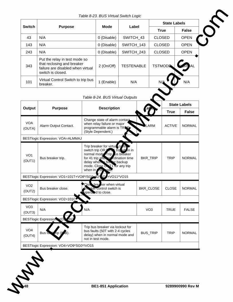
8-48 BE1-851 Application 9289900990 Rev M
Table 8-23. BUS Virtual Switch Logic
State Labels Switch Purpose Mode Label
True False
43 N/A 0 (Disable) SWITCH_43 CLOSED OPEN
143 N/A 0 (Disable) SWITCH_143 CLOSED OPEN
243 N/A 0 (Disable) SWITCH_243 CLOSED OPEN
343
Put the relay in test mode so that reclosing and breaker failure are disabled when virtual switch is closed.
2 (On/Off) TESTENABLE TSTMODE NORMAL
101 Virtual Control Switch to trip bus breaker. 1 (Enable) N/A N/A N/A
Table 8-24. BUS Virtual Outputs
State Labels Output Purpose Description Label
True False
VOA (OUTA)
Alarm Output Contact.
Change state of alarm contact when relay failure or major programmable alarm is TRUE. (Style Dependent.)
ALARM ACTIVE NORMAL
BESTlogic Expression: VOA=ALMMAJ
VO1 (OUT1)
Bus breaker trip.
Trip breaker for virtual control switch trip OR for 51 trip when in normal mode. Trip bus breaker for 41 trip after coordination time delay when in feeder backup mode. Close OUT1 for any trip when in test mode.
BKR_TRIP TRIP NORMAL
BESTlogic Expression: VO1=101T+VO8*/SG0+62*SG1+VO11*VO15
VO2 (OUT2)
Bus breaker close. Close breaker when virtual breaker control switch is operated to close.
BKR_CLOSE CLOSE NORMAL
BESTlogic Expression: VO2=101C
VO3 (OUT3)
N/A N/A VO3 TRUE FALSE
BESTlogic Expression: VO3=/IN2
VO4 (OUT4)
Bus fault trip (86B).
Trip bus breaker via lockout for bus faults (50T with 2-4 cycles delay) when in normal mode and not in test mode.
BUS_TRIP TRIP NORMAL
BESTlogic Expression: VO4=VO9*SG0*/VO15
www . El
ectric
alPar
tMan
uals
. com
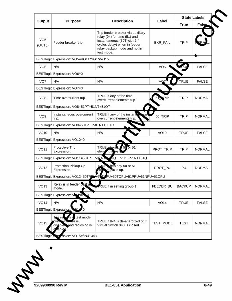
9289900990 Rev M BE1-851 Application 8-49
State Labels Output Purpose Description Label
True False
VO5 (OUT5)
Feeder breaker trip.
Trip feeder breaker via auxiliary relay (94) for time (51) and instantaneous (50T with 2-4 cycles delay) when in feeder relay backup mode and not in test mode.
BKR_FAIL TRIP NORMAL
BESTlogic Expression: VO5=VO11*SG1*/VO15
VO6 N/A N/A VO6 TRUE FALSE
BESTlogic Expression: VO6=0
VO7 N/A N/A VO7 TRUE FALSE
BESTlogic Expression: VO7=0
VO8 Time overcurrent trip. TRUE if any of the time overcurrent elements trip. 51_TRIP TRIP NORMAL
BESTlogic Expression: VO8=51PT+51NT+51QT
VO9 Instantaneous overcurrent trip.
TRUE if any of the instantaneous overcurrent elements trip. 50_TRIP TRIP NORMAL
BESTlogic Expression: VO9=50TPT+50TNT+50TQT
VO10 N/A N/A VO10 TRUE FALSE
BESTlogic Expression: VO10=0
VO11 Protective Trip Expression.
TRUE when any 50 or 51 element times out. PROT_TRIP TRIP NORMAL
BESTlogic Expression: VO11=50TPT+50TNT+50TQT+51PT+51NT+51QT
VO12 Protection Pickup Up Expression.
TRUE when any 50 or 51 element picks up. PROT_PU PU NORMAL
BESTlogic Expression: VO12=50TPPU+50TNPU+50TQPU+51PPU+51NPU+51QPU
VO13 Relay is in feeder backup mode. TRUE if in setting group 1. FEEDER_BU BACKUP NORMAL
BESTlogic Expression: VO13=SG1
VO14 N/A N/A VO14 TRUE FALSE
BESTlogic Expression: VO14=0
VO15
The relay is in test mode, breaker failure is disabled, and reclosing is disabled.
TRUE if IN4 is de-energized or if Virtual Switch 343 is closed. TEST_MODE TEST NORMAL
BESTlogic Expression: VO15=/IN4+343
www . El
ectric
alPar
tMan
uals
. com
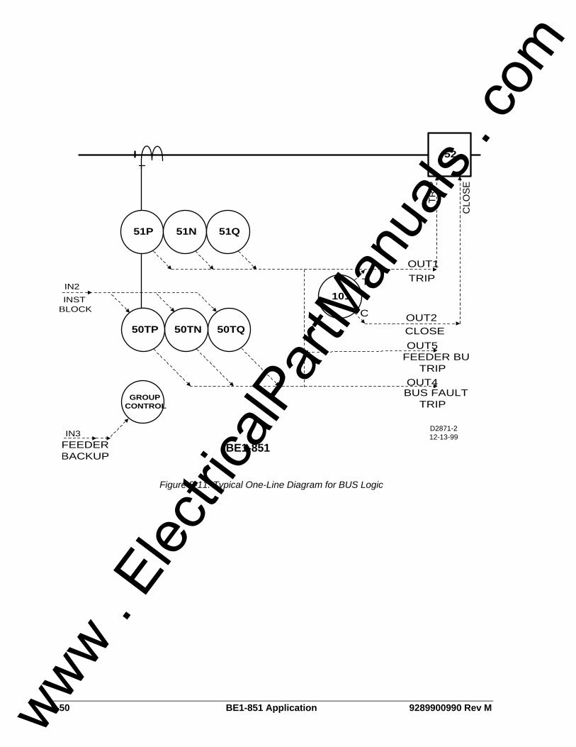
8-50 BE1-851 Application 9289900990 Rev M
52
CLO
SE
51P 51N 51Q
D2871-212-13-99
OUT1
TRIP
C
101
50TQ50TN50TP
OUT4GROUP
CONTROL
OUT5
OUT2
IN2INST
BLOCK
IN3
T
BE1-851
BUS FAULTTRIP
FEEDER BUTRIP
CLOSE
TRIP
FEEDERBACKUP
Figure 8-11. Typical One-Line Diagram for BUS Logic
www . El
ectric
alPar
tMan
uals
. com
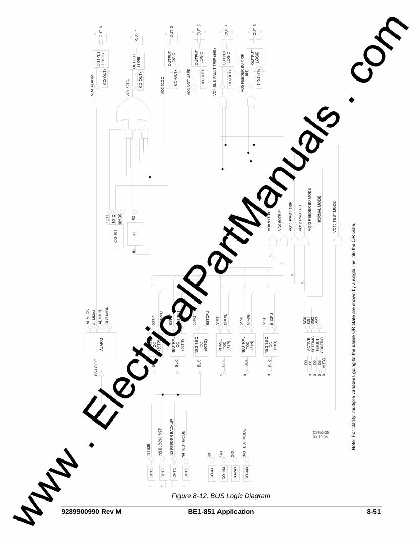
9289900990 Rev M BE1-851 Application 8-51
Figure 8-12. BUS Logic Diagram
www . El
ectric
alPar
tMan
uals
. com
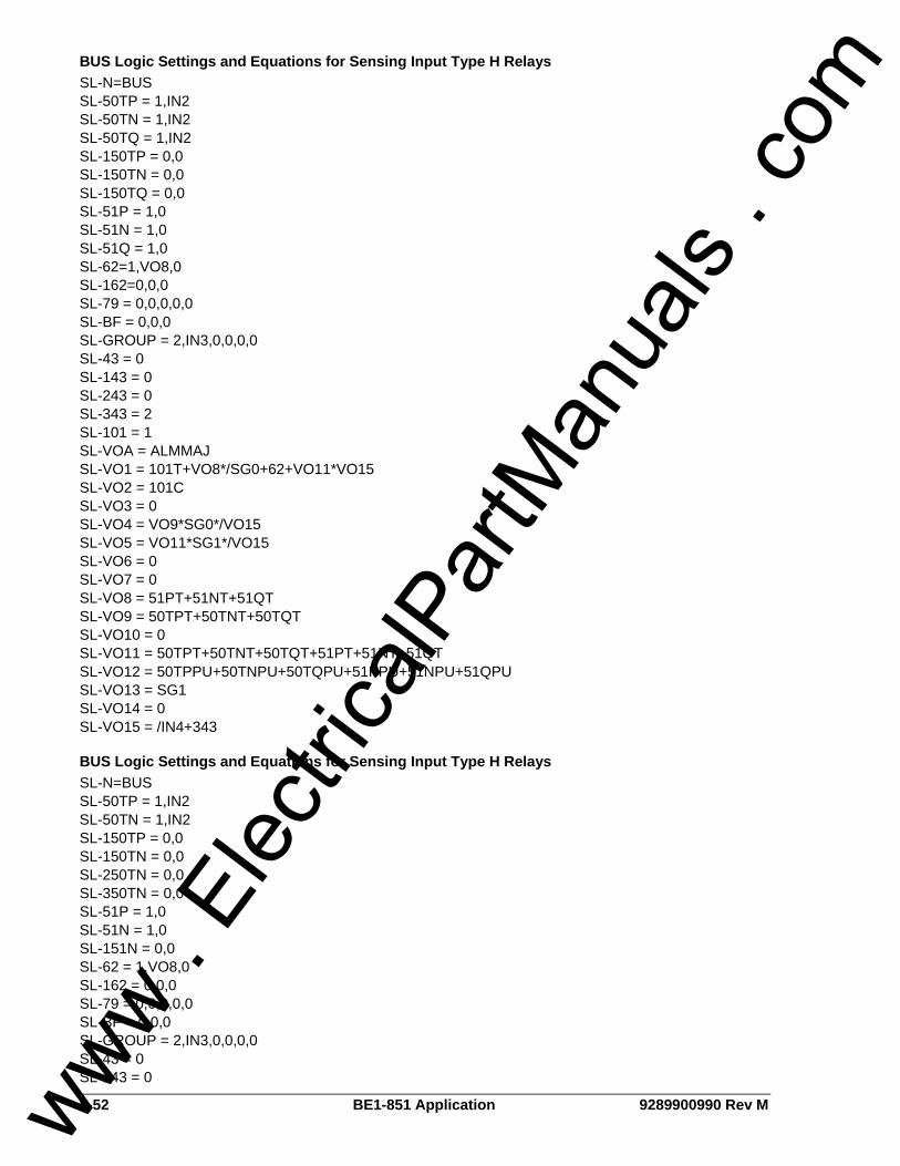
8-52 BE1-851 Application 9289900990 Rev M
BUS Logic Settings and Equations for Sensing Input Type H Relays SL-N=BUS SL-50TP = 1,IN2 SL-50TN = 1,IN2 SL-50TQ = 1,IN2 SL-150TP = 0,0 SL-150TN = 0,0 SL-150TQ = 0,0 SL-51P = 1,0 SL-51N = 1,0 SL-51Q = 1,0 SL-62=1,VO8,0 SL-162=0,0,0 SL-79 = 0,0,0,0,0 SL-BF = 0,0,0 SL-GROUP = 2,IN3,0,0,0,0 SL-43 = 0 SL-143 = 0 SL-243 = 0 SL-343 = 2 SL-101 = 1 SL-VOA = ALMMAJ SL-VO1 = 101T+VO8*/SG0+62+VO11*VO15 SL-VO2 = 101C SL-VO3 = 0 SL-VO4 = VO9*SG0*/VO15 SL-VO5 = VO11*SG1*/VO15 SL-VO6 = 0 SL-VO7 = 0 SL-VO8 = 51PT+51NT+51QT SL-VO9 = 50TPT+50TNT+50TQT SL-VO10 = 0 SL-VO11 = 50TPT+50TNT+50TQT+51PT+51NT+51QT SL-VO12 = 50TPPU+50TNPU+50TQPU+51PPU+51NPU+51QPU SL-VO13 = SG1 SL-VO14 = 0 SL-VO15 = /IN4+343
BUS Logic Settings and Equations for Sensing Input Type H Relays SL-N=BUS SL-50TP = 1,IN2 SL-50TN = 1,IN2 SL-150TP = 0,0 SL-150TN = 0,0 SL-250TN = 0,0 SL-350TN = 0,0 SL-51P = 1,0 SL-51N = 1,0 SL-151N = 0,0 SL-62 = 1,VO8,0 SL-162 = 0,0,0 SL-79 = 0,0,0,0,0 SL-BF = 0,0,0 SL-GROUP = 2,IN3,0,0,0,0 SL-43 = 0 SL-143 = 0
www . El
ectric
alPar
tMan
uals
. com
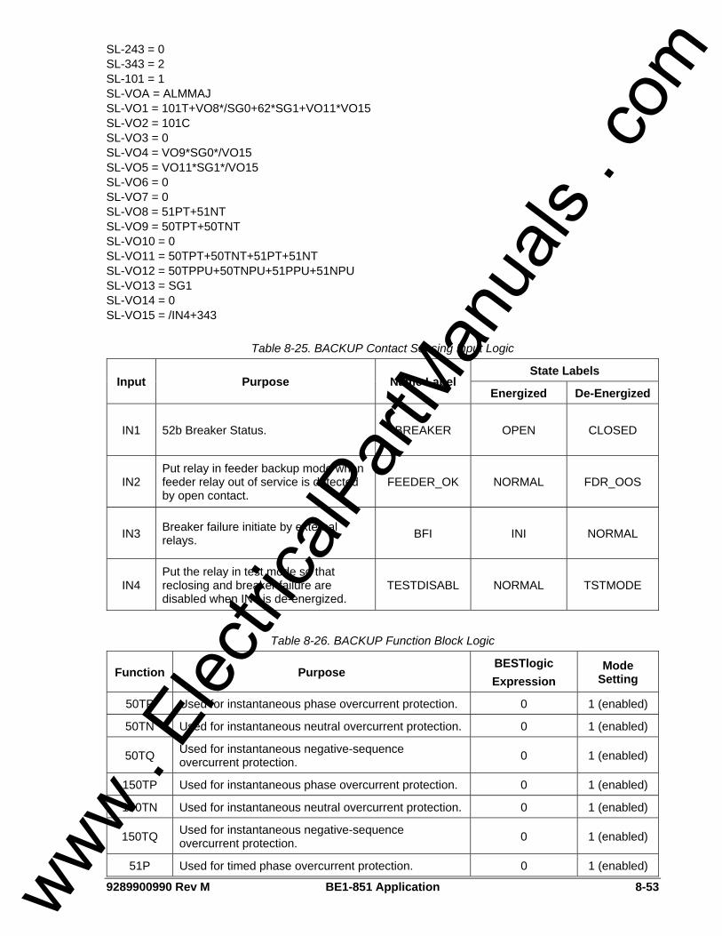
9289900990 Rev M BE1-851 Application 8-53
SL-243 = 0 SL-343 = 2 SL-101 = 1 SL-VOA = ALMMAJ SL-VO1 = 101T+VO8*/SG0+62*SG1+VO11*VO15 SL-VO2 = 101C SL-VO3 = 0 SL-VO4 = VO9*SG0*/VO15 SL-VO5 = VO11*SG1*/VO15 SL-VO6 = 0 SL-VO7 = 0 SL-VO8 = 51PT+51NT SL-VO9 = 50TPT+50TNT SL-VO10 = 0 SL-VO11 = 50TPT+50TNT+51PT+51NT SL-VO12 = 50TPPU+50TNPU+51PPU+51NPU SL-VO13 = SG1 SL-VO14 = 0 SL-VO15 = /IN4+343
Table 8-25. BACKUP Contact Sensing Input Logic
State Labels Input Purpose Name Label
Energized De-Energized
IN1 52b Breaker Status. BREAKER OPEN CLOSED
IN2 Put relay in feeder backup mode when feeder relay out of service is detected by open contact.
FEEDER_OK NORMAL FDR_OOS
IN3 Breaker failure initiate by external relays. BFI INI NORMAL
IN4 Put the relay in test mode so that reclosing and breaker failure are disabled when IN4 is de-energized.
TESTDISABL NORMAL TSTMODE
Table 8-26. BACKUP Function Block Logic
Function Purpose BESTlogic Expression
Mode Setting
50TP Used for instantaneous phase overcurrent protection. 0 1 (enabled)
50TN Used for instantaneous neutral overcurrent protection. 0 1 (enabled)
50TQ Used for instantaneous negative-sequence overcurrent protection. 0 1 (enabled)
150TP Used for instantaneous phase overcurrent protection. 0 1 (enabled)
150TN Used for instantaneous neutral overcurrent protection. 0 1 (enabled)
150TQ Used for instantaneous negative-sequence overcurrent protection. 0 1 (enabled)
51P Used for timed phase overcurrent protection. 0 1 (enabled)
www . El
ectric
alPar
tMan
uals
. com

8-54 BE1-851 Application 9289900990 Rev M
Function Purpose BESTlogic Expression
Mode Setting
51N Used for timed neutral overcurrent protection. 0 1 (enabled)
51Q Used for timed negative-sequence overcurrent protection. 0 1 (enabled)
62 N/A 0 0 (disabled)
162 N/A 0 0 (disabled)
79 N/A 0 0 (disabled)
Initiate breaker failure when breaker failure initiate expression is TRUE. VO10
BF Block breaker failure protection when relay is in test mode. VO15
1 (enabled)
Switch to setting group 1 if feeder relay is out of service as indicated by open contact from feeder relays.
/IN2
No manual logic is used. 0
No manual logic is used. 0
No manual logic is used. 0
GROUP
Fix Auto/Manual switch in the manual position only. Selection by contact sensing only. No automatic selection logic.
0
2(Binary Inputs)
Table 8-27. BACKUP Virtual Switch Logic
State Labels Switch Purpose Mode Label
True False
43 N/A 0 (Disable) SWITCH_43 CLOSED OPEN
143 N/A 0 (Disable) SWITCH_143 CLOSED OPEN
243 N/A 0 (Disable) SWITCH_243 CLOSED OPEN
343
Put the relay in test mode so that reclosing and breaker failure are disabled when virtual switch is closed.
2 (On/Off) TESTENABLE TSTMODE NORMAL
101 Virtual Control Switch to trip bus breaker. 1 (Enable) N/A N/A N/A
www . El
ectric
alPar
tMan
uals
. com
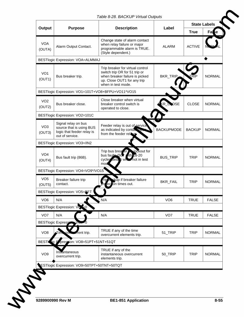
9289900990 Rev M BE1-851 Application 8-55
Table 8-28. BACKUP Virtual Outputs
State Labels Output Purpose Description Label
True False
VOA (OUTA)
Alarm Output Contact.
Change state of alarm contact when relay failure or major programmable alarm is TRUE. (Style dependent.)
ALARM ACTIVE NORMAL
BESTlogic Expression: VOA=ALMMAJ
VO1 (OUT1)
Bus breaker trip.
Trip breaker for virtual control switch trip OR for 51 trip or when breaker failure is picked up. Close OUT1 for any trip when in test mode.
BKR_TRIP TRIP NORMAL
BESTlogic Expression: VO1=101T+VO8+BFPU+VO11*VO15
VO2 (OUT2)
Bus breaker close. Close breaker when virtual breaker control switch is operated to close.
BKR_CLOSE CLOSE NORMAL
BESTlogic Expression: VO2=101C
VO3 (OUT3)
Signal relay on bus source that is using BUS logic that feeder relay is out of service.
Feeder relay is out of service as indicated by contact open from the feeder relays.
BACKUPMODE BACKUP NORMAL
BESTlogic Expression: VO3=/IN2
VO4 (OUT4)
Bus fault trip (86B).
Trip bus breaker via lockout for bus faults (50T with 18-20 cycles delay) when not in test mode.
BUS_TRIP TRIP NORMAL
BESTlogic Expression: VO4=VO9*/VO15
VO5 (OUT5)
Breaker failure trip contact.
Trip backup if breaker failure protection times out. BKR_FAIL TRIP NORMAL
BESTlogic Expression: VO5=BFT
VO6 N/A N/A VO6 TRUE FALSE
BESTlogic Expression: VO6=0
VO7 N/A N/A VO7 TRUE FALSE
BESTlogic Expression: VO7=0
VO8 Time overcurrent trip. TRUE if any of the time overcurrent elements trip. 51_TRIP TRIP NORMAL
BESTlogic Expression: VO8=51PT+51NT+51QT
VO9 Instantaneous overcurrent trip.
TRUE if any of the instantaneous overcurrent elements trip.
50_TRIP TRIP NORMAL
BESTlogic Expression: VO9=50TPT+50TNT+50TQT
www . El
ectric
alPar
tMan
uals
. com
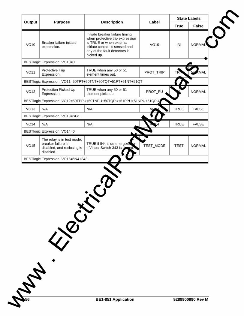
8-56 BE1-851 Application 9289900990 Rev M
State Labels Output Purpose Description Label
True False
VO10 Breaker failure initiate expression.
Initiate breaker failure timing when protective trip expression is TRUE or when external initiate contact is sensed and any of the fault detectors is picked up.
VO10 INI NORMAL
BESTlogic Expression: VO10=0
VO11 Protective Trip Expression.
TRUE when any 50 or 51 element times out. PROT_TRIP TRIP NORMAL
BESTlogic Expression: VO11=50TPT+50TNT+50TQT+51PT+51NT+51QT
VO12 Protection Picked Up Expression.
TRUE when any 50 or 51 element picks up. PROT_PU PU NORMAL
BESTlogic Expression: VO12=50TPPU+50TNPU+50TQPU+51PPU+51NPU+51QPU
VO13 N/A N/A VO13 TRUE FALSE
BESTlogic Expression: VO13=SG1
VO14 N/A N/A VO14 TRUE FALSE
BESTlogic Expression: VO14=0
VO15
The relay is in test mode, breaker failure is disabled, and reclosing is disabled.
TRUE if IN4 is de-energized or if Virtual Switch 343 is closed. TEST_MODE TEST NORMAL
BESTlogic Expression: VO15=/IN4+343
www . El
ectric
alPar
tMan
uals
. com
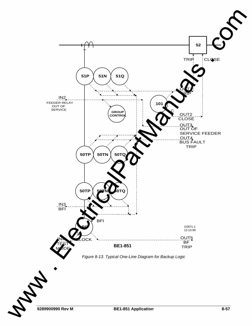
9289900990 Rev M BE1-851 Application 8-57
D2871-112-13-99
52
OUT1
TRIP
51P 51N 51Q
OUT5
101T
C
CLOSE
OUT2
OUT3
TRIP
CLOSE
OUT OFSERVICE FEEDER
GROUPCONTROL
IN2FEEDER RELAY
OUT OFSERVICE
BE1-851
OUT4
50TQ50TN50TP
BF
BFTRIP
50TQ50TN50TP
IN3BFI
BUS FAULTTRIP
IN4TESTMODE
BFI
BLOCK
Figure 8-13. Typical One-Line Diagram for Backup Logic
www . El
ectric
alPar
tMan
uals
. com
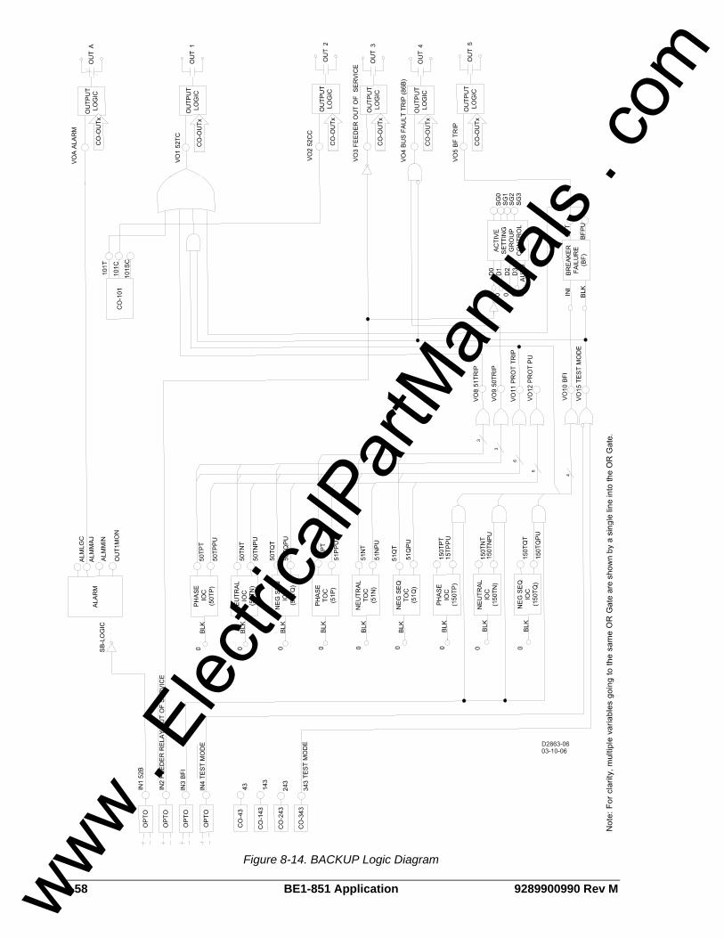
8-58 BE1-851 Application 9289900990 Rev M
Figure 8-14. BACKUP Logic Diagram
www . El
ectric
alPar
tMan
uals
. com
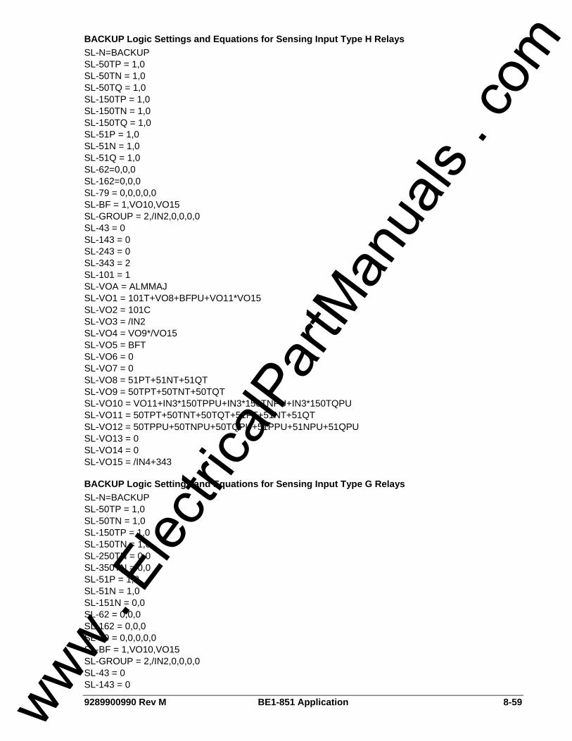
9289900990 Rev M BE1-851 Application 8-59
BACKUP Logic Settings and Equations for Sensing Input Type H Relays SL-N=BACKUP SL-50TP = 1,0 SL-50TN = 1,0 SL-50TQ = 1,0 SL-150TP = 1,0 SL-150TN = 1,0 SL-150TQ = 1,0 SL-51P = 1,0 SL-51N = 1,0 SL-51Q = 1,0 SL-62=0,0,0 SL-162=0,0,0 SL-79 = 0,0,0,0,0 SL-BF = 1,VO10,VO15 SL-GROUP = 2,/IN2,0,0,0,0 SL-43 = 0 SL-143 = 0 SL-243 = 0 SL-343 = 2 SL-101 = 1 SL-VOA = ALMMAJ SL-VO1 = 101T+VO8+BFPU+VO11*VO15 SL-VO2 = 101C SL-VO3 = /IN2 SL-VO4 = VO9*/VO15 SL-VO5 = BFT SL-VO6 = 0 SL-VO7 = 0 SL-VO8 = 51PT+51NT+51QT SL-VO9 = 50TPT+50TNT+50TQT SL-VO10 = VO11+IN3*150TPPU+IN3*150TNPU+IN3*150TQPU SL-VO11 = 50TPT+50TNT+50TQT+51PT+51NT+51QT SL-VO12 = 50TPPU+50TNPU+50TQPU+51PPU+51NPU+51QPU SL-VO13 = 0 SL-VO14 = 0 SL-VO15 = /IN4+343
BACKUP Logic Settings and Equations for Sensing Input Type G Relays SL-N=BACKUP SL-50TP = 1,0 SL-50TN = 1,0 SL-150TP = 1,0 SL-150TN = 1,0 SL-250TN = 0,0 SL-350TN = 0,0 SL-51P = 1,0 SL-51N = 1,0 SL-151N = 0,0 SL-62 = 0,0,0 SL-162 = 0,0,0 SL-79 = 0,0,0,0,0 SL-BF = 1,VO10,VO15 SL-GROUP = 2,/IN2,0,0,0,0 SL-43 = 0 SL-143 = 0
www . El
ectric
alPar
tMan
uals
. com
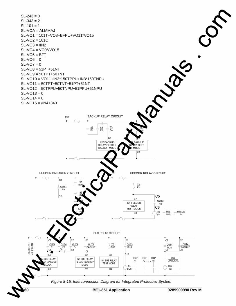
8-60 BE1-851 Application 9289900990 Rev M
SL-243 = 0 SL-343 = 2 SL-101 = 1 SL-VOA = ALMMAJ SL-VO1 = 101T+VO8+BFPU+VO11*VO15 SL-VO2 = 101C SL-VO3 = /IN2 SL-VO4 = VO9*/VO15 SL-VO5 = BFT SL-VO6 = 0 SL-VO7 = 0 SL-VO8 = 51PT+51NT SL-VO9 = 50TPT+50TNT SL-VO10 = VO11+IN3*150TPPU+IN3*150TNPU SL-VO11 = 50TPT+50TNT+51PT+51NT SL-VO12 = 50TPPU+50TNPU+51PPU+51NPU SL-VO13 = 0 SL-VO14 = 0 SL-VO15 = /IN4+343
Figure 8-15. Interconnection Diagram for Integrated Protective System
www . El
ectric
alPar
tMan
uals
. com

9289900990 Rev M BE1-851 Application 8-61
MISCELLANEOUS LOGIC SETTINGS There are five logic variables that are classified as miscellaneous logic expressions. These expressions are: SG-TARG, SG-TRIGGER, SB-DUTY, SB-LOGIC, and SA-RESET. The equations associated with these variables determine how the BE1-851 responds to conditions such as when to target what triggers fault reporting, defining breaker status monitoring, and setup for remote alarm/target reset provisions. These variables aren’t included in any of the BESTlogic preprogrammed schemes. However, the factory default equations are compatible with each scheme. The default miscellaneous expressions are common among the preprogrammed and custom schemes. When a preprogrammed scheme is modified or a new scheme is created, the miscellaneous logic expressions should be reviewed to ensure desired performance. The default expressions for the miscellaneous logic settings are as follows: SB-LOGIC=/IN1 SG-TRIGGER=BFT+VO11,BFPU+VO12,0 SP-79ZONE=0 SG-TARG=50TA/50TB/50TC/50TN/50TQ/62/162/BF/150TA/150TB/150TC/150TN/150TQ/51A/51B/51C/51N/51Q,0 SA-RESET=0 SB-DUTY=0,0.000e+00,0
Table 8-29 lists the miscellaneous commands and the sections of this manual where detailed information about each command may be found.
Table 8-29. Miscellaneous Logic Expressions
Command Reference
SB-LOGIC Section 6, Reporting and Alarm Functions
SG-TRIGGER Section 6, Reporting and Alarm Functions
SP-79ZONE Section 4, Protection and Control
SG-TARG Section 6, Reporting and Alarm Functions
SA-RESET Section 6, Reporting and Alarm Functions
SB-DUTY Section 6, Reporting and Alarm Functions
APPLICATION TIPS
Trip Circuit Continuity and Voltage Monitor OUT1 has a built in trip circuit voltage and continuity monitor that drives logic variable OUT1MON. This variable can be used to improve breaker failure logic or to automatically enhance security during testing. If the relay detects a loss of voltage or continuity in the breaker trip circuit, it is possible to speed up fault clearing time by bypassing the breaker failure timer. Since relay failure and breaker failure are covered by different backup actions, it is desirable to reduce common mode failure mechanisms. It is recommended that separate control power fuses or breakers supply the feeder breaker and feeder protection circuits. The equation for the Breaker Failure Trip logic (VO5) can be modified by ORing the Breaker Failure Initiate with the expression VO10*OUT1MON. VO10 is designated in each of the preprogrammed logic schemes as the Breaker Failure Initiate expression. Example 1 illustrates how the BFT logic expression is modified. It is important that the breaker failure timer bypass logic also be disabled in test mode. Example 2 shows the expression for blocking the upstream instantaneous element. Figure 8-16 illustrates using the trip circuit continuity monitor in breaker failure logic. Example 1. Breaker failure trip expression: SL-VO5=BFT+VO10*OUT1MON*IN4*/343 Example 2. Block upstream instantaneous expression: SL-VO4=VO12*/VO5*/OUT1MON*IN4*/343 If the internal breaker failure function block is not being used, the trip circuit continuity and voltage monitor alarm can be used to detect when the test paddle or test switches have been opened. This will automatically place the relay in the test mode. Each of the preprogrammed logic schemes has logic to detect when the relay is out of service for test. This enables the backup logic and enhances security. It
www . El
ectric
alPar
tMan
uals
. com
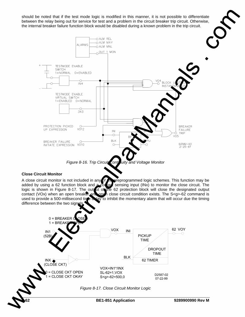
8-62 BE1-851 Application 9289900990 Rev M
should be noted that if the test mode logic is modified in this manner, it is not possible to differentiate between the relay being out for service for test and a problem in the circuit breaker trip circuit. Otherwise, the internal breaker failure function block would be disabled during a known problem in the trip circuit.
Figure 8-16. Trip Circuit Continuity and Voltage Monitor
Close Circuit Monitor A close circuit monitor is not included in any of the preprogrammed logic schemes. This function may be added by using a 62 function block and a contact sensing input (INx) to monitor the close circuit. The logic is shown in Figure 8-17. The output of the 62 protection block will close the designated output contact (VOx) when an open breaker and open close circuit condition exists. The S<g>-62 command is used to provide a 500-millisecond time delay to inhibit the momentary alarm that will occur due the timing difference between the two signals.
Figure 8-17. Close Circuit Monitor Logic
www . El
ectric
alPar
tMan
uals
. com

9289900990 Rev M BE1-851 Application 8-63
High-Speed Reclose Each reclose time delay can be set as low as 100 milliseconds. If the application requires a reclose time delay of less than 250 milliseconds, it is recommended that the close logic expression be modified to prevent mis-coordination between the TRIP and CLOSE outputs. A hold timer for each output relay is provided to hold the output closed for approximately 200 milliseconds. This prevents the relay contacts from opening before the breaker auxiliary contact interrupts the trip coil current. For high-speed reclosing, the hold timer must be disabled so that the output contact follows the VO1 output expression. To modify the logic, add the expression “reclose 79C AND NOT trip VO1” to the close logic. Examples 1 and 2 show a close expression and hold disable setting for high-speed reclosing. Figure 8-18 illustrates this high-speed reclose interlock logic scheme. Example 1. Close expression: SL-VO2=79C*/VO1+101C Example 2. Hold disable setting: SG-HOLD1=0
Figure 8-18. High-Speed Reclose Interlock Logic
Block Load Tap Changer A block load tap changer output is not provided in any of the preprogrammed logic schemes. One of the output relays can be programmed to operate when the recloser is running (79RNG) and wired to energize a normally closed auxiliary relay. The 79RNG logic variable is high when any of the timers are timing and low when the reclosing function is in a lockout or reset state.
Block Neutral and Negative-Sequence Protection The neutral and negative-sequence overcurrent elements provide greater sensitivity to unbalanced faults than the phase overcurrent elements because they can be set to pickup below balanced three phase load. This can lead to a mis-operation during periods of load imbalance. The BE1-851 provides a neutral and negative-sequence demand function that allows monitoring and alarming to prevent load imbalances.
www . El
ectric
alPar
tMan
uals
. com

8-64 BE1-851 Application 9289900990 Rev M
However, distribution systems with single pole fault clearing and switching devices or long single-phase laterals may have mis-operations during switching activities. The preprogrammed logic schemes provide for the use of a cutoff switch to block the ground and negative-sequence 50T (used for low set instantaneous) and the 51 (inverse time) function blocks during switching activities. This is the most conservative approach. The protection engineer may wish to evaluate this strategy based on his/her system, operating practices, and setting practices. For instance, on systems with wye-connected loads, the ground units are most sensitive to this situation. It may not be necessary to block the instantaneous units if their settings prevent them from tripping for a switching imbalance. To maintain proper coordination, the logic of the feeder relays may be interconnected with the upstream bus relay to block the equivalent ground and/or negative-sequence function blocks in the upstream relay.
Setting Group Selection The BE1-851 Overcurrent Protection System provides multiple settings groups for adaptive relaying. The preprogrammed logic schemes barely tap the flexibility that is available. The following examples illustrate how the settings groups can be adapted for different conditions and how different setting groups can be used to vary the system logic. Example 1. Adapting the relay settings for different conditions. In overcurrent protection systems, the source conditions can have a major impact on sensitivity, coordination intervals, and clearing times. Generally, the pickup and time dial settings are a compromise between a normal condition and a worst-case condition. Contact logic from the position of the source breakers can select which settings group is active. To do this, assign input D0 or D1 to a contact sensing input. Set the Setting Group Selection Mode at 2 for binary coded selection. If D0 is set, Group 0 will be selected when the input is off (binary code 00). Group 1 will be selected when the input is on (binary code 01). Similarly, if D1 is set, Group 2 will be selected when the input is on (binary coded 10). This logic is useful in a situation where two transformers feed a single bus or two busses have a bus tie between them. The feeder and bus relays must be coordinated for the situation where only one source is in service (bus tie open or one transformer out of service). However, when both sources are in service, such as when the bus tie is closed, each bus relay sees only half of the current for a fault. This results in poor sensitivity and slow clearing time for the bus relays. Example 2. Adapting the logic in different setting groups. The logic in most of the preprogrammed logic schemes can be varied in each of the different setting groups. This is accomplished by disabling functions by setting their primary settings at zero. It is also possible to do more sophisticated modification of the logic in each of the different setting groups by using the active setting group logic variables SG0, SG1, SG2, and SG3 in the BESTlogic expressions.
Output Contact Seal-In Trip contact seal-in circuits have historically been provided with electromechanical relays. These seal-in circuits consisted of a dc coil in series with the relay trip contact and a seal-in contact in parallel with the trip contact. The seal-in feature serves several purposes for the electromechanical relays. One is to provide mechanical energy to drop the target. Second is to carry the dc tripping current from the induction disk contact that may not have significant closing torque for a low resistance connection. The third is to prevent the relay contact from dropping out until the current has been interrupted by the 52a contacts in series with the trip coil. If the tripping contact opens before the dc current in interrupted, the contact may be damaged. The first two of these items are not an issue for solid-state relays but the third item is an issue. To prevent the output relay contacts from opening prematurely, a 200 millisecond hold timer can be selected with the SG-HOLDn=1 command. Refer to Section 3, Input and Output Functions, for more information on this feature. If the protection engineer desires seal-in logic with feed back from the breaker position logic, he/she can provide this logic by modifying the BESTlogic expression for the tripping output. To do this, use one of the general purpose timers 62 or 162 and set it for Mode 1 (Pickup/Dropout Timer). Set the timer logic so that it is initiated by the breaker position input and set the timer for two cycles pickup and two cycles dropout. Then AND the timer output with the tripping output and OR it into the expression for the tripping output. The same can be done for the closing output. Figure 8-19 provides a seal-in logic diagram.
www . El
ectric
alPar
tMan
uals
. com

9289900990 Rev M BE1-851 Application 8-65
OUTPUTLOGIC
OPTO OUTPUTLOGIC
INI62
BLK
IN1
52b
+
+
62
-
TRIPPINGLOGIC
52TC
CLOSINGLOGIC
52CC OUT2
OUT1
+
-
52a 52b
52TC 52CC
D2590-1003-23-98
VO1
VO2VO7
VO6
Figure 8-19. Output Seal-In Logic Diagram
Example 1. Turn off the hold timer for Output 1: SG-HOLD1=0;SG-HOLD2=0 Set the timer logic: SL-62=1,IN1,0 Set the pickup and dropout times: S#-62=2c,2c Set the output logic: VO1=101T+BFPU+VO11+VO6*/62 VO2=101C+79C+VO7*62 VO6=VO1*/62 VO7=VO2*62
Oscillograhpic Recording of Breaker Closures and Openings How do I program the relay to create an oscillographic record when the breaker closes or opens? Monitor the circuit breaker status by connecting the 52b contacts to IN1. Set a general-purpose logic timer (62) for Mode 1 (Pickup/Dropout), initiated by not input one (/IN1) and no blocking with T1 equal to 0.15 seconds, and T2 equal to 0.015 seconds (SL-62=1,?in1,0 and S<#>-62=0.015,0.015). Program a virtual output (VO10) to be TRUE (high) when the input to IN1is FALSE and the 62 output is False or when the IN1 input is TRUE and the 62 Output is TRUE (VO10=/IN1*/62+IN1*62). Set the SG-TRIGGER command for a logic trigger when VO10 is TRUE (SG-TRIGGER=<TRIP trigger>,<PICKUP trigger>,VO10). Here is the scenario: The breaker has been open for a while. Therefore, IN1 input is TRUE and the 62 Output is FALSE. When the breaker closes, the IN1 input becomes FALSE and because the 62 Output is FALSE, Virtual Output 10 goes TRUE for the duration of T1 (15 milliseconds). After the T1 time delay, the 62 Output goes TRUE and remains TRUE until the initiate input (IN1) goes FALSE for the duration of T2. Virtual Output 10 was TRUE for the 15 milliseconds time delay of T1 and triggered the oscillographic record when the breaker closed. Before the breaker opens, IN1 if FALSE and the 62 output is TRUE. When the breaker opens, IN1 becomes TRUE longer than time delay T2. During that time T2, Virtual Output 10 is TRUE because both IN1 and the 62 Output are TRUE because both IN1 and the 62 Output are TRUE. This time, an oscillographic record is triggered because the circuit breaker opened.
NOTE This example is based on the Feeder_2, Feeder_3, or Feeder_4 preprogrammed logic schemes.
www . El
ectric
alPar
tMan
uals
. com

8-66 BE1-851 Application 9289900990 Rev M
This page intentionally left blank.
www . El
ectric
alPar
tMan
uals
. com

9289900990 Rev M BE1-851 Security i
SECTION 9 • SECURITY TABLE OF CONTENTS
SECTION 9 • SECURITY.......................................................................................................................... 9-1
INTRODUCTION.................................................................................................................................... 9-1 Setting Password Protection .............................................................................................................. 9-1
Figures Figure 9-1. General Operation Screen, Global Security Tab .................................................................... 9-2 Figure 9-2. General Operation, Global Security Tab with Passwords Shown .......................................... 9-2
Tables Table 9-1. Password Protection Settings .................................................................................................. 9-3
www . El
ectric
alPar
tMan
uals
. com

ii BE1-851 Security 9289900990 Rev M
This page intentionally left blank.
www . El
ectric
alPar
tMan
uals
. com

9289900990 Rev M BE1-851 Security 9-1
SECTION 9 • SECURITY INTRODUCTION In this section, security, in the form of multilevel password protection, is discussed along with the information required for protecting specific function groups and user interface components against unauthorized access. Passwords provide access security for three distinct functional access areas: Settings, Reports, and Control. Each functional area can be assigned a unique password or one password can be assigned to multiple areas. A global password is used to access all three of the functional areas. BE1-851 passwords are not case sensitive; either lowercase or uppercase letters may be entered. Password security only limits write operations; passwords are never required to read information from any area. Additional security is provided by controlling the functional areas that can be accessed from a particular communication port. For example, security can be configured so that access to Control commands from the rear RS-232 port (COM 1) is denied. Then, an attempt to issue a Control command through COM 1 will cause the relay to respond with an ACCESS DENIED and/or INVALID PASSWORD message. This will occur whether a valid password is entered or not. When configuring communication port access areas, you should be aware that the front RS-232 port (COM 0) and the front panel HMI are treated as the same port. The communication ports and password parameters act as a two-dimensional control to limit changes. For a command to be accepted, the entered password must be correct and the command must be entered through a valid port. Only one password can be active at one time for any area or port. For example, if a user gains write access at COM1, then users at other areas (COM0, front panel HMI, and COM2) will not be able to gain write access until the user at COM1 uses the EXIT command to release access control. If a port holding access privileges sees no activity (command entered or HMI key pressed) for approximately five minutes, access privileges and any pending changes will be lost. This feature ensures that password protection cannot be accidentally left in a state where access privileges are enabled for one area and other areas locked out for an indefinite period. If password protection is disabled, then entering ACCESS= followed by no password or any alphanumeric character string will obtain access to the unprotected area(s).
Setting Password Protection Password protection is configured for each access area port and communication port using BESTCOMS. Alternately, password protection can be configured using the GS-PW ASCII command. To configure password protection using BESTCOMS, select General Operation from the Screens pull-down menu. Then select the Global Security tab. Refer to Figure 9-1.
www . El
ectric
alPar
tMan
uals
. com
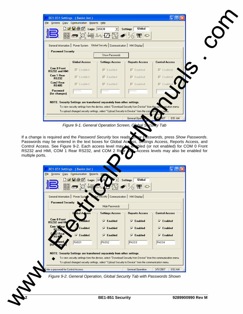
9-2 BE1-851 Security 9289900990 Rev M
Figure 9-1. General Operation Screen, Global Security Tab
If a change is required and the Password Security box reads Show Passwords, press Show Passwords. Passwords may be entered in the text boxes for Global Access, Settings Access, Reports Access, and Control Access. See Figure 9-2. Each access level may be enabled (or not enabled) for COM 0 Front RS232 and HMI, COM 1 Rear RS232, and COM 2 Rear 485. Access levels may also be enabled for multiple ports.
Figure 9-2. General Operation, Global Security Tab with Passwords Shown
www . El
ectric
alPar
tMan
uals
. com

9289900990 Rev M BE1-851 Security 9-3
Table 9-1 lists password protection settings.
Table 9-1. Password Protection Settings
Setting Range/Purpose
Password User defined alphanumeric string with a maximum of 8 characters. A setting of 0 (zero) disables password protection.
Com ports 0 = Front RS-232 port 1 = Rear RS-232 port 2 = Rear RS-485 port
www . El
ectric
alPar
tMan
uals
. com

9-4 BE1-851 Security 9289900990 Rev M
This page intentionally left blank.
www . El
ectric
alPar
tMan
uals
. com
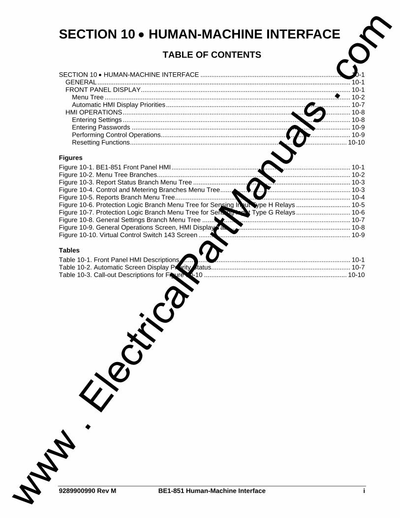
9289900990 Rev M BE1-851 Human-Machine Interface i
SECTION 10 • HUMAN-MACHINE INTERFACE TABLE OF CONTENTS
SECTION 10 • HUMAN-MACHINE INTERFACE ................................................................................... 10-1
GENERAL............................................................................................................................................ 10-1 FRONT PANEL DISPLAY.................................................................................................................... 10-1
Menu Tree ........................................................................................................................................ 10-2 Automatic HMI Display Priorities...................................................................................................... 10-7
HMI OPERATIONS.............................................................................................................................. 10-8 Entering Settings .............................................................................................................................. 10-8 Entering Passwords ......................................................................................................................... 10-9 Performing Control Operations......................................................................................................... 10-9 Resetting Functions........................................................................................................................ 10-10
Figures Figure 10-1. BE1-851 Front Panel HMI................................................................................................... 10-1 Figure 10-2. Menu Tree Branches........................................................................................................... 10-2 Figure 10-3. Report Status Branch Menu Tree ....................................................................................... 10-3 Figure 10-4. Control and Metering Branches Menu Tree........................................................................ 10-3 Figure 10-5. Reports Branch Menu Tree................................................................................................. 10-4 Figure 10-6. Protection Logic Branch Menu Tree for Sensing Input Type H Relays .............................. 10-5 Figure 10-7. Protection Logic Branch Menu Tree for Sensing Input Type G Relays .............................. 10-6 Figure 10-8. General Settings Branch Menu Tree .................................................................................. 10-7 Figure 10-9. General Operations Screen, HMI Display Tab ................................................................... 10-8 Figure 10-10. Virtual Control Switch 143 Screen .................................................................................... 10-9
Tables Table 10-1. Front Panel HMI Descriptions .............................................................................................. 10-1 Table 10-2. Automatic Screen Display Priority Status............................................................................. 10-7 Table 10-3. Call-out Descriptions for Figure 10-10 ............................................................................... 10-10
www . El
ectric
alPar
tMan
uals
. com

ii BE1-851 Human-Machine Interface 9289900990 Rev M
This page intentionally left blank.
www . El
ectric
alPar
tMan
uals
. com
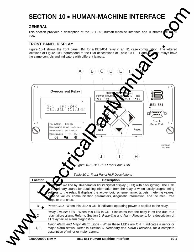
9289900990 Rev M BE1-851 Human-Machine Interface 10-1
SECTION 10 • HUMAN-MACHINE INTERFACE GENERAL This section provides a description of the BE1-851 human-machine interface and illustrates the menu tree.
FRONT PANEL DISPLAY Figure 10-1 shows the front panel HMI for a BE1-851 relay in an H1 case configuration. The lettered locations of Figure 10-1 correspond to the HMI descriptions of Table 10-1. F1 and S1 style relays have the same controls and indicators with different layouts.
Figure 10-1. BE1-851 Front Panel HMI
Table 10-1. Front Panel HMI Descriptions
Locator Description
A
Display - Two line by 16-character liquid crystal display (LCD) with backlighting. The LCD is the primary source for obtaining information from the relay or when locally programming settings to the relay. It displays the active logic scheme name, targets, metering values, demand values, communication parameters, diagnostic information, and the menu tree steps or branches.
B Power LED - When this LED is ON, it indicates operating power is applied to the relay.
C Relay Trouble LED - When this LED is ON, it indicates that the relay is off-line due to a relay failure alarm. Refer to Section 6, Reporting and Alarm Functions, for a description of all relay failure alarm diagnostics.
D, E Minor Alarm and Major Alarm LEDs - When these LEDs are ON, it indicates a minor or major alarm status. Refer to Section 6, Reporting and Alarm Functions, for a complete description of minor or major alarms.
www . El
ectric
alPar
tMan
uals
. com

10-2 BE1-851 Human-Machine Interface 9289900990 Rev M
Locator Description F Trip LED - When this LED is flashing ON, it indicates that a protective element is pickup
up. When this LED in ON continuously, it indicates that a trip output is closed. The LED is sealed-in if a protective trip has occurred and there are targets being displayed.
G Communication Port 0 - This is an RS-232 serial port. A computer terminal or PC running BESTCOMS software or terminal emulation software (such as Windows® Hyper Terminal) can be connected to this port so that the user may send commands to the relay or receive reports from the relay. Communication with the relay uses a simple ASCII command language.
H Reset Pushbutton Switch - Pushing this switch resets data including sealed-in trip targets, the Trip LED, peak demand currents, and alarms. It aborts the editing session without saving changes.
I Scrolling Pushbuttons - Scrolls UP/DOWN/LEFT/RIGHT through the LCD’s menu tree or when in the Edit mode.
J Edit Pushbutton Switch - Enable settings changes.
K Identification Label - This ID label lists the relay’s sensing input current range, power supply type, serial number, and style number.
Menu Tree The menu tree has six branches. These branches are:
1. REPORT STATUS. Display and resetting of general status information such as targets, alarms, recloser status, etc.
2. CONTROL. Operation of control functions such as controlling virtual switches, selection of active setting group, etc.
3. METERING. Display of real time metering values. 4. REPORTS. Display and resetting of report information such as time and date, demand registers,
breaker duty statistics, etc. 5. PROTECTION LOGIC. Display and setting of protective function setting parameters such as
pickups, time delays, etc. 6. GENERAL SETTINGS. Display and setting of non-protective function setting parameters such as
communication, CT ratios, connections, etc. Each screen in the menu tree is numbered in the upper left hand corner of the screen. This number indicates the current branch and level in the menu tree structure so that you do not loose track of where you are when you have left the top level of the menu tree. You scroll through each level of the menu tree by using the RIGHT and LEFT scrolling keys. To go to a level of detail, you use the DOWN scrolling key. Each time you go to a lower level in the menu tree, another number is added to the screen number separated by a period. Figures 10-2 through 10-8 illustrate all branches in the menu tree.
Figure 10-2. Menu Tree Branches
www . El
ectric
alPar
tMan
uals
. com
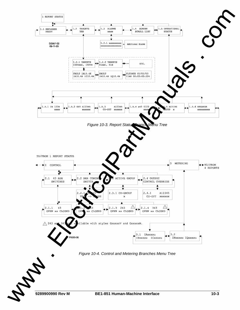
9289900990 Rev M BE1-851 Human-Machine Interface 10-3
Figure 10-3. Report Status Branch Menu Tree
Figure 10-4. Control and Metering Branches Menu Tree
www . El
ectric
alPar
tMan
uals
. com
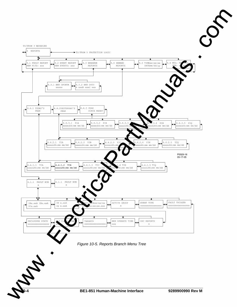
10-4 BE1-851 Human-Machine Interface 9289900990 Rev M
Figure 10-5. Reports Branch Menu Tree
www . El
ectric
alPar
tMan
uals
. com
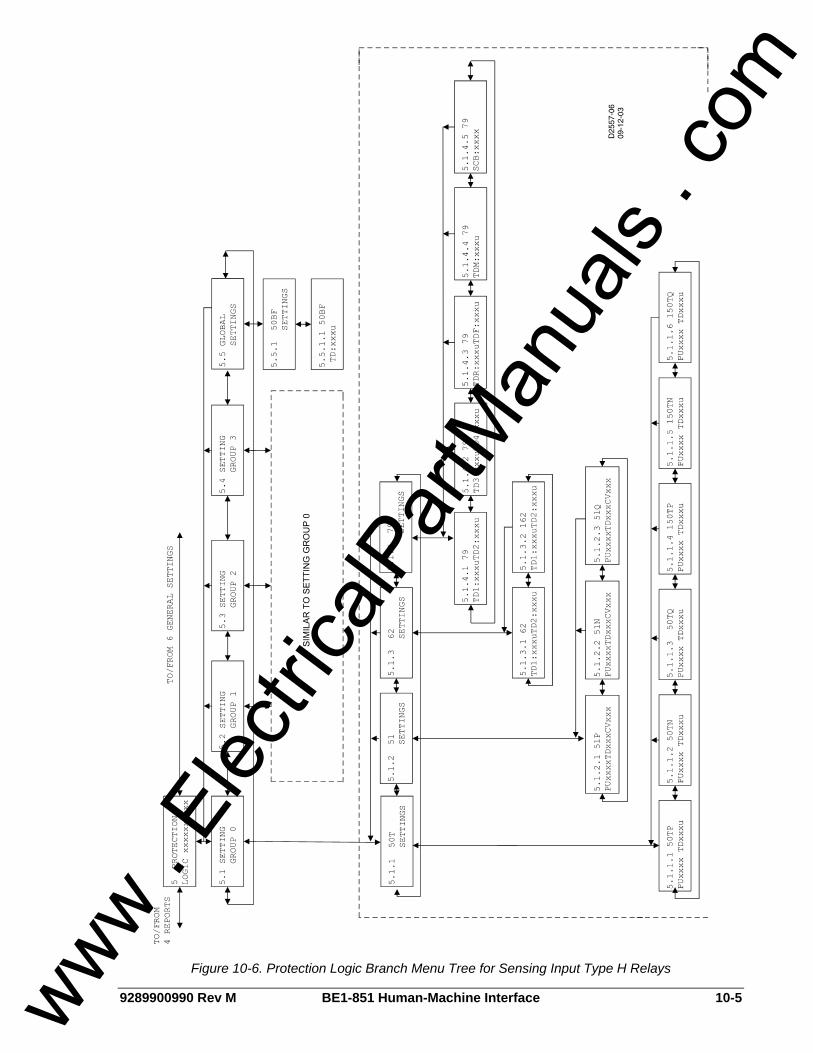
9289900990 Rev M BE1-851 Human-Machine Interface 10-5
Figure 10-6. Protection Logic Branch Menu Tree for Sensing Input Type H Relays
www . El
ectric
alPar
tMan
uals
. com
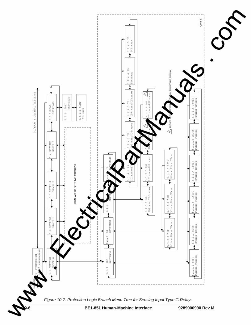
10-6 BE1-851 Human-Machine Interface 9289900990 Rev M
Figure 10-7. Protection Logic Branch Menu Tree for Sensing Input Type G Relays
www . El
ectric
alPar
tMan
uals
. com
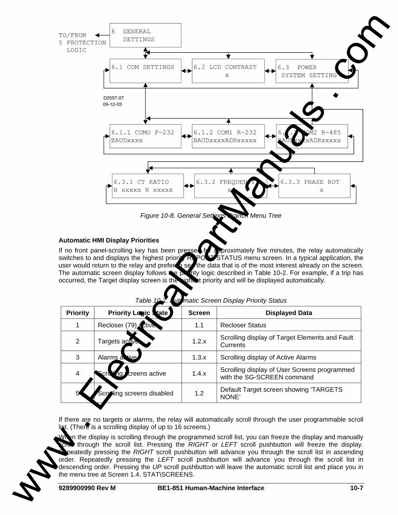
9289900990 Rev M BE1-851 Human-Machine Interface 10-7
Figure 10-8. General Settings Branch Menu Tree
Automatic HMI Display Priorities If no front panel-scrolling key has been pressed for approximately five minutes, the relay automatically switches to and displays the highest priority REPORT STATUS menu screen. In a typical application, the user would return to the relay and prefer to see the data that is of the most interest already on the screen. The automatic screen display follows the priority logic described in Table 10-2. For example, if a trip has occurred, the Target display screen is the highest priority and will be displayed automatically.
Table 10-2. Automatic Screen Display Priority Status
Priority Priority Logic State Screen Displayed Data
1 Recloser (79) active 1.1 Recloser Status
2 Targets active 1.2.x Scrolling display of Target Elements and Fault Currents
3 Alarms active 1.3.x Scrolling display of Active Alarms
4 Scrolling screens active 1.4.x Scrolling display of User Screens programmed with the SG-SCREEN command
5 Scrolling screens disabled 1.2 Default Target screen showing ‘TARGETS NONE’
If there are no targets or alarms, the relay will automatically scroll through the user programmable scroll list. (There is a scrolling display of up to 16 screens.) When the display is scrolling through the programmed scroll list, you can freeze the display and manually scroll through the scroll list. Pressing the RIGHT or LEFT scroll pushbutton will freeze the display. Repeatedly pressing the RIGHT scroll pushbutton will advance you through the scroll list in ascending order. Repeatedly pressing the LEFT scroll pushbutton will advance you through the scroll list in descending order. Pressing the UP scroll pushbutton will leave the automatic scroll list and place you in the menu tree at Screen 1.4, STAT\SCREENS.
www . El
ectric
alPar
tMan
uals
. com
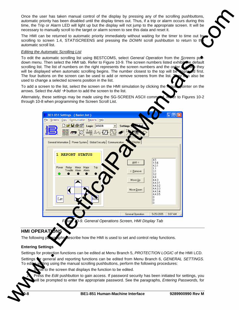
10-8 BE1-851 Human-Machine Interface 9289900990 Rev M
Once the user has taken manual control of the display by pressing any of the scrolling pushbuttons, automatic priority has been disabled until the display times out. Thus, if a trip or alarm occurs during this time, the Trip or Alarm LED will light up but the display will not jump to the appropriate screen. It will be necessary to manually scroll to the target or alarm screen to see this data and reset it. The HMI can be returned to automatic priority immediately without waiting for the timer to time out by scrolling to screen 1.4, STAT\SCREENS and pressing the DOWN scroll pushbutton to return to the automatic scroll list.
Editing the Automatic Scrolling List To edit the automatic scrolling list using BESTCOMS, select General Operation from the Screens pull-down menu. Then select the HMI tab. Refer to Figure 10-9. The screen numbers listed exhibit the default scrolling list. The list of numbers on the right represents the screen numbers and the order in which they will be displayed when automatic scrolling begins. The number closest to the top will be displayed first. The four buttons on the screen can be used to add or remove screens from the list. They can also be used to change a selected screens position in the list. To add a screen to the list, select the screen on the HMI simulation by clicking the mouse pointer on the arrows. Select the Add button to add the screen to the list. Alternately, these settings may be made using the SG-SCREEN ASCII command. Refer to Figures 10-2 through 10-8 when programming the Screen Scroll List.
Figure 10-9. General Operations Screen, HMI Display Tab
HMI OPERATIONS The following paragraphs describe how the HMI is used to set and control relay functions.
Entering Settings Settings for protection functions can be edited at Menu Branch 5, PROTECTION LOGIC of the HMI LCD. Settings for general and reporting functions can be edited from Menu Branch 6, GENERAL SETTINGS. To edit a setting using the manual scrolling pushbuttons, perform the following procedures:
1. Scroll to the screen that displays the function to be edited. 2. Press the Edit pushbutton to gain access. If password security has been initiated for settings, you
will be prompted to enter the appropriate password. See the paragraphs, Entering Passwords, for
www . El
ectric
alPar
tMan
uals
. com

9289900990 Rev M BE1-851 Human-Machine Interface 10-9
details on entering passwords from the HMI. Once access has been gained, the Edit LED will be lighted and a cursor will appear in the first settings field on the screen.
3. Press the UP or DOWN scrolling key to select the desired setting. Some settings require entering a number one character at a time. For example, to enter a 51 pickup as 7.3 amps, you would press the UP pushbutton until the 7 is showing. Then, press the RIGHT pushbutton to move the cursor over and press the UP pushbutton until the “.” is showing. Then press the RIGHT pushbutton to move the cursor over and press the UP pushbutton until the 3 is showing. Other settings require scrolling through a list of selections. For example, you would move the cursor over to the CRV field and then scroll through a list of available TCC curves.
4. Once all of the settings on the screen have been entered, press the Edit pushbutton a second time and the settings will be validated. If the settings are in range, the screen will flash CHANGES SAVED, and the Edit LED will go out. If you want to abort the edit session without changing any settings, press the Reset pushbutton before you press the Edit pushbutton the second time. The screen will flash CHANGES LOST and the Edit LED will go out.
Entering Passwords If password security has been initiated for a function, the HMI will prompt you to enter a password when the Edit pushbutton is pressed. To gain access, you must enter the appropriate password. A field of eight asterisks appears with the cursor located under the leftmost character position. You can enter passwords by performing the following procedure:
1. Press the UP or DOWN scrolling pushbuttons until the proper first character of the password appears. Pressing the UP pushbutton scrolls through the alphabet and then the numbers in ascending order. Pressing DOWN scrolls through the numbers and then the alphabet in descending order.
2. Press the RIGHT scrolling pushbutton to move the cursor to the next character of the password and select the appropriate character.
3. Continue the process until the entire password has been spelled out. If the password is less than eight characters, leave the remaining asterisks in place instead of entering blanks.
4. Press the Edit pushbutton to enter the password. If the proper password has been entered, the screen will flash ACCESS GRANTED. If an incorrect password has been entered, the screen will flash ACCESS DENIED and the Edit LED will go out.
5. Once you gain access, it remains in affect for five minutes. As long as you continue to press the Edit key for a function for which you have gained access, the five-minute timer will be refreshed and you will not be prompted for a password.
Performing Control Operations Control operations can be executed at Menu Branch 2, CONTROL of the HMI LCD. These functions allow you to control the state of virtual switches, override logic, control the active setting group, and control the state of output contacts. All of these functions work similarly to the process of entering settings in that you press the Edit pushbutton for the action to be executed. Figure 10-10 shows Virtual Switch 143 as an example of a virtual switch screen. See Section 4, Protection and Control, for more details on the x43 and 101 functions. Table 10-3 describes each of the locators shown on Figure 10-10. The user programmable label for this switch has been set to RCL_DISABL. The TRUE (closed) state label has been set to DISABLD. The FALSE (open) state label has been set to ENABLED. The logical mode for this application would be set to Mode 2 (On/Off switch).
2.1.2 RCL_DISABLENABLED< DISABLD
D2849-1606-22-99
A B
CDE Figure 10-10. Virtual Control Switch 143 Screen
www . El
ectric
alPar
tMan
uals
. com

10-10 BE1-851 Human-Machine Interface 9289900990 Rev M
Table 10-3. Call-out Descriptions for Figure 10-10
Locator Description
A This is the screen number. It eases navigation by indicating the current branch and level in the menu tree structure.
B User selectable label (meaningful name) for specific virtual switches. The ‘Switch 143’ identification label is set to ‘RCL_DISABL’.
C User selectable label for the closed (1) state for Virtual Switch 143. The ‘Switch 143’ closed label is set to ‘DISABLD’.
D An arrow icon indicates the current switch position (status). In Figure 10-10, the status is open (0), which is labeled ‘ENABLD’.
E User selectable label for the open (0) state for Virtual Switch 143. The ‘Switch 143’ open label is set to ‘ENABLED’.
To operate the switch, you would use the following procedure:
1. Use the manual scrolling pushbuttons to scroll to Screen 2.1.x (43 AUX SWITCHES). If the screen has been placed in the automatic scroll list and it is scrolling at the time, simply wait for it to appear and press the RIGHT or LEFT scroll pushbutton to stop the scrolling on Screen 2.1.x.
2. Press the Edit pushbutton to gain access. If password security has been initiated for control functions, you will be prompted to enter the appropriate password. Once access is gained to the control function, the Edit LED will light.
3. Press the UP or DOWN scrolling key to select the new state (as indicated by the arrow) for the switch. The “P” selection will pulse the state of the switch from its present state to the opposite state for approximately 200 milliseconds. The allowable states are dependent upon the logic mode setting for the switch. If the switch is set to Mode 1(On/Off/Pulse), the “P” (pulse) selection will give an “:INVALID PARAMETER” error. If set to Mode 3 (Off/Momentary On), selecting one of the two states will give an “INVALID PARAMETER” error.
4. Press the Edit pushbutton a second time and the switch will change to the selected position, the screen will flash CHANGES SAVED, and the Edit LED will go out. If you want to abort the editing session without changing any controls, press the Reset pushbutton before you press the Edit pushbutton the second time. The screen will flash CHANGES LOST and the Edit LED will go out.
Resetting Functions The Reset pushbutton is context sensitive. Its function is dependent upon the screen that is presently being displayed. For example, pressing the Reset key when the Demand screen is displayed will reset the demands but it will not reset the alarms, etc. It is necessary to scroll through the menu tree to the Alarm screen to reset an alarm. You are not prompted for a password when using the Reset key. There are two BESTlogic variables associated with the HMI Reset pushbutton. Logic variable TRSTKEY becomes TRUE when the Reset pushbutton is pressed while the Target screen is displayed. Logic variable ARSTKEY becomes TRUE when the Reset pushbutton is pressed while the Alarm screen is displayed. See Section 8, Application, Application Tips, for examples on the use of these variables.
www . El
ectric
alPar
tMan
uals
. com
9289900990 Rev M BE1-851 ASCII Command Interface i
SECTION 11 • ASCII COMMAND INTERFACE TABLE OF CONTENTS
SECTION 11 • ASCII COMMAND INTERFACE..................................................................................... 11-1
INTRODUCTION.................................................................................................................................. 11-1 SERIAL PORT ..................................................................................................................................... 11-1
RS-485 Port...................................................................................................................................... 11-1 RS-232 Ports .................................................................................................................................... 11-1
ASCII COMMAND INTERFACE .......................................................................................................... 11-1 Command Structure ......................................................................................................................... 11-1 Using the ASCII Command Interface ............................................................................................... 11-2
Human to Machine ASCII Command Operations......................................................................... 11-2 Command Text File Operations.................................................................................................... 11-2 Embedding Comments into ASCII Text Files ............................................................................... 11-2
Miscellaneous Command Descriptions ............................................................................................ 11-3 HELP Command........................................................................................................................... 11-3 ACCESS Command ..................................................................................................................... 11-3 EXIT Command ............................................................................................................................ 11-4
Settings (S) Command Descriptions ................................................................................................ 11-4 Reading All Settings ..................................................................................................................... 11-4 Reading Specific Groups of Settings............................................................................................ 11-5 Reading Logic Settings................................................................................................................. 11-6 Configuring the Serial Port Communication Protocol ................................................................... 11-7
COMMAND SUMMARY....................................................................................................................... 11-8 Miscellaneous Commands ............................................................................................................... 11-8 Metering Commands ........................................................................................................................ 11-9 Report Commands ........................................................................................................................... 11-9 Setting Command........................................................................................................................... 11-12 Alarm Setting Commands .............................................................................................................. 11-12 Breaker Monitor Setting Commands .............................................................................................. 11-13 General Setting Commands........................................................................................................... 11-13 Programmable Logic Setting Commands ...................................................................................... 11-15 User Programmable Name Setting Command............................................................................... 11-17 Protection Setting Commands........................................................................................................ 11-17 Global Commands.......................................................................................................................... 11-18
Tables Table 11-1. Communication Settings ...................................................................................................... 11-8
www . El
ectric
alPar
tMan
uals
. com

ii BE1-851 ASCII Command Interface 9289900990 Rev M
This page intentionally left blank.
www . El
ectric
alPar
tMan
uals
. com

9289900990 Rev M BE1-851 ASCII Command Interface 11-1
SECTION 11 • ASCII COMMAND INTERFACE INTRODUCTION Relay and power system information can be retrieved from a remote location using the ASCII command interface. The ASCII command interface is also used to enter settings, retrieve reports and metering information, and perform control operations. A communication port on the relay front panel provides a temporary, local interface for communication. Communication ports on the rear panel provide a permanent communication interface. Front and rear panel communication ports can be connected to computers, terminals, serial printers, modems, and intermediate communication/control interfaces such as RS-232 serial multiplexors. BE1-851 communication protocols support ASCII and binary data transmissions. ASCII data is used to send and receive human readable data and commands. Binary data is used for computer communication and transmission of raw oscillographic fault data, if available. Modbus™ and other common protocols are also available. An instruction manual (9289900992) for using Modbus™ protocol with the BE1-851 is available as well as instruction manual (9289900995) for using DNP protocol. For information about other protocols, consult your Basler Electric Representative.
SERIAL PORT Communication connections consist of two standard RS-232 ports, one RS-485 port, and one IRIG port. BE1-851 communication protocol is compatible with readily available modem/terminal software. If required, password protection provides security against unauthorized operation. Detailed information about making communication connections is provided in Section 12, Installation.
RS-485 Port RS-485 terminal block connections are located on the rear panel and designated COM 2. This port supports half-duplex, multi-drop operation. Multi-drop (polled mode) operation is possible if a polling address is programmed for the port.
RS-232 Ports Two female RS-232 (DB-9) connectors are provided. One port is located on the front panel and is designated COM 0. Another port is located on the rear panel and is designated COM 1. Both ports support full-duplex operation. Polled operation is possible at the rear port using a simple RS-232 splitter if a polling address is programmed for COM 1.
ASCII COMMAND INTERFACE A computer terminal or PC running terminal emulation software can be used at any of the three serial ports to send commands to the relay. Simple ASCII command language is used to communicate with the relay. When the relay receives a command, it responds with the appropriate action. ASCII commands can be used in human machine interactions and in batch download type operations.
Command Structure An ASCII command consists of a string made up of one or two letters followed by a hyphen and an object name.
xy-object name
x Specifies the general command function.
y Specifies the command subgroup.
Object Name Defines the specific object to which the command refers.
Examples of object names include 51N (neutral inverse time overcurrent function) and PIA (phase A peak current demand register). A command string entered alone is a read command. A command string followed by an equal sign (=) and one or more parameters is a write command.
www . El
ectric
alPar
tMan
uals
. com

11-2 BE1-851 ASCII Command Interface 9289900990 Rev M
General command functions are organized into five major groups plus one group of miscellaneous commands. These groups are listed below: CONTROL (C): Control commands perform select-before-operate control actions such as circuit
breaker tripping and closing and active setting group changes. Subgroups include Select (S) and Operate (O).
GLOBAL (G): One Global command performs operations that don’t fall into the other general groups. The command for reading and changing passwords (GS-PW) is the only global command available.
METERING (M): Commands in this group report all real-time metering values. No subgroup is used with metering commands.
REPORTS (R): These commands read and reset reporting functions such as time and date, demand registers, and breaker duty statistics.
SETTINGS (S): This group contains all of the setting parameters that govern relay function. Subgroups include Setting Groups 0, 1, 2, and 3, Protection Settings (P) not in setting groups, Alarm Settings (A), Breaker Monitor Settings (B), General Settings (G), and Logic Settings (L).
MISCELLANEOUS: Miscellaneous commands include Access, Exit, and Help. Note that only the first letter of these commands must be entered; entering the full command name is optional.
Using the ASCII Command Interface
Human to Machine ASCII Command Operations When using ASCII commands, settings can be read and changed on a function-by-function basis. The mnemonic format of the commands helps the user interact with the relay. It isn’t necessary to remember all of the object names. Most commands don’t require that you specify a complete object name. If the first two letters of a command are entered, the relay will respond with all applicable object names. ASCII Command Examples:
1. Obtain the breaker operations count by entering RB (Report Breaker). The BE1-851 responds with the operations counter value along with all other breaker report objects. If you know that the object name for the breaker operations counter is OPCNTR, you can enter RB-OPCNTR and read only the number of breaker operations.
Partial object names are also supported. This allows multiple objects to be read or reset at the same time. 2. Read all peak-since-reset demand current registers. Entering RD-PI (Report Demand – Peak
Current (I)) will return demand values and time stamps for Phase A, B, C, Neutral, and Negative Sequence current. To read only the Neutral demand value, the full object name (RD-PIN) is entered. Entering RD-PI=0 resets all five of the peak-since-reset current demand registers.
Command Text File Operations In command text file operations, an ASCII text file operations, and ASCII text file of commands is created and sent to the relay. For example, the S command is used to retrieve a complete list of settings from the relay in ASCII command format. This list of commands is captured, saved to a file, edited with any ASCII text editor, and then uploaded to the relay. Because the number of relay settings is so large, loading settings with a text file is the preferred method of setting the BE1-851.
Embedding Comments into ASCII Text Files Adding comments to ASCII settings files is an easy way to organize and label your settings. A Comment line is started with two forward slashes (//) followed by the comment text. When the relay encounters // in a text file, it ignores all the following characters until the next carriage return or linefeed character. Example of embedding comments in a settings file: //Group0 is used during normal operation S0-50TP=7.50,0m;S0-50TN=2.5,0m,,, //Group1 is used during cold load pickup S1-50TP=0,0m;S1-50TN=0,0m;S1-toTQ=0,0m
www . El
ectric
alPar
tMan
uals
. com

9289900990 Rev M BE1-851 ASCII Command Interface 11-3
Miscellaneous Command Descriptions
HELP Command The HELP (H) command provides general information on command syntax and functionality when the manual is not available. Entering HELP or H provides information about using the HELP command. HELP1 or H1 returns a complete list of relay commands. Entering HELP <cmd> where <cmd> is a specific command, returns information about the use and format of the command along with an example of how the command is used. HELP Command Purpose: Obtain help on command operation Syntax: HELP {cmd} or H {cmd} for help on {cmd}, H1 for command list Example: HELP, H1, H SG-COM
ACCESS Command Before making settings changes through a communication port, the ACCESS command must be used to obtain programming access. Enter ACCESS=<password> to obtain access to change settings associated with the password. Different passwords give the ability or access to perform different operations. The relay will deny access if an invalid password is entered or if another user has already been granted programming access through another serial port or at the front panel. Only one user can have access at any one time. Even if password protection is not used, it is still necessary to obtain access so that accidental changes are prevented. If password protection is disabled, then ACCESS= will be accepted in place of a password. The relay will respond with ACCESS GRANTED: GLOBAL if the command entered was received and executed. The relay will respond with an error message and a question mark (?) if the command could not be executed. The ACCESS (A) command and the EXIT (E) command are used to change relay settings, reset report registers, and enable control commands through a serial port. These commands prevent changes from being made concurrently from two areas. For example, a user cannot make changes through COM0 at the same time a remote user is making changes through COM2. ACCESS Command Purpose: Read/Set Access level in order to change settings Syntax: ACCESS[={password}] Example: ACCESS=851 Comments: The ACCESS command must be used before any changes to settings can be made.
Available ACCESS privileges are summarized in the following paragraphs. READ-ONLY. This is the default access privilege when no passwords are active. Read-only access allows you to read settings and reports but not make settings changes. PRIVILEGE G: GLOBAL ACCESS. Global access is obtained by password G (PWG). Global access permits entry of any command with no restrictions. PRIVILEGE S: SETTING ACCESS. Setting access is obtained by password S (PWS). Setting access allows changes to any settings. PRIVILEGE C: CONTROL ACCESS. Control access is obtained by password C (PWC). Control access enables relay control operations. PRIVILEGE R: REPORT ACCESS. Report access is obtained by password R (PWR). Report access enables report operations to be performed. An access privilege is obtained only when the appropriate password is entered. When a valid password is entered, the relay responds with the access privilege provided by the password entered. If an invalid password is entered, an error message is returned. If password protection is disabled in one or more privileges, then entering any string will provide access to the unprotected privileges.
www . El
ectric
alPar
tMan
uals
. com

11-4 BE1-851 ASCII Command Interface 9289900990 Rev M
ACCESS Command Examples: 1. A valid password is entered.
Sent: ACCESS=OPENUP Received: ACCESS GRANTED : GLOBAL
2. An invalid password is entered. Sent: ACCESS=POENUP Received: ACCESS DENIED INVALID PASSWORD
3. The current access privilege is read. Sent: ACCESS Received: ACCESS : GLOBAL
EXIT Command If changes have been made, the new data will be saved or discarded after using the EXIT command. Prior to saving or discarding any changes, you must confirm that you wish to exit the programming mode. There are three exit options: Y (YES), N (NO), or C (CONTINUE). EXIT Command Purpose: Exit the programming mode. Syntax: EXIT (Note: Relay will prompt for verification.) Example: EXIT Comments: It’s important to make all programming changes before executing the EXIT command.
This prevents a partial or incomplete protection scheme from being implemented. When access privileges are obtained, all programming changes are made to a temporary, scratchpad copy of relay settings. These changes aren’t saved to nonvolatile memory and initiated until the EXIT command is invoked and confirmed. After the EXIT command is entered, the relay prompts to confirm that the new data should be saved. Three options, Y, N, or C are available. Entering Y will save the data. If N is entered, the relay will clear the changes and resume operating with the old settings. Entering C will abort the EXIT command and allow programming to continue. EXIT Command Example:
Release programming privileges and save settings changes. Sent: EXIT<CR> Received: SAVE CHANGES (Y/N/C)? Prompt to save YES, NO, or CONTINUE Sent: Y<CR> Confirmation to SAVE CHANGES Received: CHANGES SAVED Confirmation that CHANGES WERE SAVED
Settings (S) Command Descriptions
Reading All Settings All user programmable settings can be listed using the S command. This read-only command is useful for documenting relay status during installation. The settings retrieved by the S command can be saved to a standard text file and sent to another relay to be configured with the same settings. This type of settings transfer takes less than one minute. S Command Purpose: Read all relay setting parameters. Syntax: S Example: S
www . El
ectric
alPar
tMan
uals
. com

9289900990 Rev M BE1-851 ASCII Command Interface 11-5
The S command returns the values of relay setting parameters in the same form that they are programmed. It can be used at the end of a programming session to make a record of the relay settings. If saved in a file, the report can be sent to another BE1-851 that will use the same settings. Because the report that is created is a set of commands, sending the report to a different relay re-programs that relay with the settings contained in the S report.
Reading Specific Groups of Settings While the S command is useful for reading all relay settings, several commands are available to read specific groups of settings. Note: In the examples of this section, relay responses are printed in Courier New typeface. SA Command Purpose: Read all alarm settings for Major and Minor alarms. Syntax: SA Example: SA SA Command Example: Read all alarm settings. >SA SA-BKR1= 0,0; SA-BKR2= 0,0; SA-BKR3= 0,0 A-DIP=0.00; SA-DIN=0.00; SA-DIQ=0.00 A-LGC=0 A-MAJ=25 A-MIN=26 A-RESET=0
SB Command Purpose: Read all breaker settings. Syntax: SB Example: SB SB Command Example: Read all breaker settings. >SB SB-DUTY=0,0.000e+00,0
SB-LOGIC=/62
SG Command Purpose: Read all general settings. Syntax: SG Example: SG SG Command Example: Obtain a report of all general settings. >SG SG-CLK=M,24,0 SG-DST= 1 SG-DSTSTART= 3, 0, 2, 0, 2 SG-DSTSTOP= 11, 0, 2, 0, 1 SG-UTC= 0, 0, 60 SG-COM0=9600,A0,P0,R1,X1; SG-COM1=9600,A0,P0,R1,X1 SG-COM2=9600,A0,P0,R1,X0,MF1,MPN,MR10,MS1,PW0 SG-CTP=1; SG-CTN=1 SG-DIP=15; SG-DIN= 1; SG-DIQ= 1 SG-DSPP=F; SG-DSPN=F
www . El
ectric
alPar
tMan
uals
. com
11-6 BE1-851 ASCII Command Interface 9289900990 Rev M
SG-FREQ=60 SG-HOLDA=0; SG-HOLD1=1; SG-HOLD2=1; SG-HOLD3=0 SG-HOLD4=0; SG-HOLD5=1 SG-ID=BE1-851,SUBSTATION_1 SG-IN1= 4, 16; SG-IN2= 4, 16; SG-IN3= 4, 16; SG-IN4= 4, 16 SG-PHROT=1 SG-SCREEN1=4.5; SG-SCREEN2=1.5.6; SG-SCREEN3=4.3.1; SG-SCREEN4=1.1 SG-SCREEN5=3.1; SG-SCREEN6=3.2; SG-SCREEN7=4.4; SG-SCREEN8=4.4.3 SG-SCREEN9=4.4.3.1; SG-SCREEN10=4.4.3.2;SG-SCREEN11=4.4.3.3;SG-SCREEN12=4.4.3.4 SG-SCREEN13=4.4.3.5;SG-SCREEN14=0; SG-SCREEN15=0; SG-SCREEN16=0
SG-SGCON= 5 SG-DATADUMP= 0 SG-TARG=50TA/50TB/50TC/50TN/62/162/BF/150TA/150TB/150TC/150TN/250TN/350TN/51A/51B/51C/51N/262/362/151N,0
SG-TRIGGER=BFT+VO11,BFPU+VO12,0
SN Command Purpose: Read/Set User Programmable Names Syntax: SN[-{var}[={name},{TRUE label},{FALSE label}] Example: SN or SN-VO1=TRIP,CLOSED,OPEN or SN-IN1=BREAKER,OPEN,CLOSED SN Command Example: Read the programmed labels for the alarm output (OUTA). >SN-VOA VOA_LABEL,TRUE,FALSE S<g> Command Purpose: Read all Protection settings Syntax: S{g} where g=setting group 0-3 or # for all groups Example: S# or S0 or S1 S<g> Command Example: Obtain a list of settings for settings group 2. >S2 S2-50TP=0.00, 0m; S2-50TN=0.00, 0m; S2-50TQ=0.00, 0m
S2-150TP=0.00, 0m; S2-150TN=0.00, 0m; S2-150TQ=0.00, 0m S2-51P=0.00,0.0,V2; S2-51N=0.00,0.0,V2; S2-51Q=0.00,0.0,V2 S2-62= 0m, 0m S2-162= 0m, 0m S2-791= 0m; S2-792= 0m; S2-793= 0m; S2-794= 0m S2-79R= 10s; S2-79F=1.0s; S2-79M= 60s S2-79SCB=0 SP-79ZONE=0 SP-BF= 0m SP-CURVE= 0.2663, 0.0339, 1.0000, 1.2969, 0.5000 SP-GROUP1= 0, 0, 0, 0,51P; SP-GROUP2= 0, 0, 0, 0,51P SP-GROUP3= 0, 0, 0, 0,51P
Reading Logic Settings The SL command is used to view the names of available logic schemes in memory. It also will return all of the logic equations for a specific logic scheme.
SL Command Purpose: Obtain Setting Logic Information Syntax: SL:[{name}] Example: SL, SL: or SL:BASIC-OC Comments: No password access is required to read settings.
www . El
ectric
alPar
tMan
uals
. com

9289900990 Rev M BE1-851 ASCII Command Interface 11-7
Entering SL by itself returns all of the logic equations associated with the active logic scheme. Entering SL: returns the names of all available logic schemes. Entering SL:<name> returns all logic equations and settings for the named logic scheme. SL Command Examples:
1. Read the available logic schemes in memory. >SL USER, FEEDER_1, FEEDER_2, FEEDER_3, FEEDER_4, BUS, BACKUP, NONE
2. Read all logic settings associated with the BACKUP logic scheme. >SL:BACKUP SL-50TP:1,0; SL-50TN:1,0; SL-50TQ:1,0 SL-150TP:1,0; SL-150TN:1,0; SL-150TQ:1,0 SL-51P:1,0; SL-51N:1,0; SL-51Q:1,0 SL-62:0,0,0 SL-162:0,0,0 SL-79:0,0,0,0,0 SL-BF:1,VO10,VO15 SL-GROUP:2,/IN2,0,0,0,0 SL-43:0 SL-143:0 SL-243:0 SL-343:2 SL-101:1 SL-VOA:ALMMAJ SL-VO1:101T+VO8+BFPU+VO11*VO15 SL-VO2:101C SL-VO3:/IN2 SL-VO4:VO9*/VO15 SL-VO5:BFT SL-VO6:0 SL-VO7:0 SL-VO8:51PT+51NT+51QT SL-VO9:50TPT+50TNT+50TQT SL-VO10:VO11+150TPPU*IN3+150TNPU*IN3+150TQPU*IN3 SL-VO11:50TPT+50TNT+50TQT+51PT+51NT+51QT SL-VO12:50TPPU+50TNPU+50TQPU+51PPU+51NPU+51QPU SL-VO13:0 SL-VO14:0 SL-VO15:343+/IN4
Configuring the Serial Port Communication Protocol The BE1-851 Overcurrent Protection System has three independent communications ports for serial communications. A computer terminal or PC running a terminal emulation program such as Windows® Terminal can be connected to any of the three ports so that commands may be sent to the relay. Communication with the relay uses a simple ASCII command language. When a command is entered through a serial port, the relay responds with the appropriate action. The ASCII command language is designed for use in both human to machine interactions and in batch download type operations. Operation of the ASCI commands is described in detail in Section 11, ASCII Command Interface. The ASCII communication byte framing parameters are fixed at 8 data bits, no parity, and 1 stop bit. View or change these settings using the SG-COM command. These parameters are also settable from the human-machine interface (HMI) from Screen 6.1.x. There are several additional settings described in Table 11-1 to further customize the ASCII communications. The additional parameters for page length, reply acknowledgement, and software handshaking are only settable from the ASCII command interface using the SG-COM command. www .
Elec
tricalP
artM
anua
ls . c
om

11-8 BE1-851 ASCII Command Interface 9289900990 Rev M
Table 11-1. Communication Settings
Parameter Description Range Default
Baud Baud Rate 300, 600, 1200, 2400, 4800, 9600, or 19K
9600
A Address for Polled Operation
A0 (disabled) A1 to A65534
A0
P Page Length P0 (no page mode) P1 to P40
P0
R Reply Acknowledgement
R0 (disabled) R1 (enabled)
R1
X Xon/Xoff (hardware handshaking) setting
X0 (disabled) X1 (enabled)
X1 (COM0,1) X0 (COM2)
SG-COM Command Purpose: Read/Set serial communications protocol Syntax: SG-COM[#[={baud},A{addr},P{pglen},R{reply ack},X{XON ena}]] Example: SG-COM0=9600 or SG-COM1=9600,A0,P24,R1,X1 Comments: Password access privilege G or S is required to change settings. # = port number. (0 = front, 1 = rear RS-232, 2 = rear RS-485) SG-COM Command Examples:
1. Program the front communication port for 1200 baud. >SG-COM0=1200
2. Read the communication settings for all ports. Sent: >SG-COM Received: SG-COM0=9600,A0,P0,R1,X1;
SG-COM1=9600,A0,P0,R1,X1
SG-COM2=9600,A0,P0,R1,X0,MF1,MPN,MR10,MS1,PW0
If the ‘A’ parameter is set at a nonzero value, the relay will ignore all commands that are not preceded by the proper address number. If an address of 0 is programmed, the relay will respond with an error message for any command preceded by an address. With polling enabled, a command preceded by 0 is treated as a global command. All networked relays will execute the command, but no relay will respond to the command. This avoids communication bus conflicts. The front panel communication port (COM0) is not configured for polling, so an attempt to program a non-zero address will result in an error message.
COMMAND SUMMARY
Miscellaneous Commands
ACCESS Command Purpose: Read/Set Access level in order to change settings Syntax: ACCESS[={password}] Example: ACCESS=851 Reference: Section 11, ASCII Command Interface, Miscellaneous Command Descriptions
www . El
ectric
alPar
tMan
uals
. com

9289900990 Rev M BE1-851 ASCII Command Interface 11-9
EXIT Command Purpose: Exit programming mode Syntax: EXIT - Note: Relay will prompt for verification Example: EXIT Reference: Section 11, ASCII Command Interface, Miscellaneous Command Descriptions
HELP Command Purpose: Obtain help on command operation Syntax: HELP {cmd} or H {cmd} for help on {cmd}, H1 for command list Example: HELP, H1, H SG-COM Reference: Section 11, ASCII Command Interface, Miscellaneous Command Descriptions
Metering Commands
M Command Purpose: Read all metered values Syntax: M Example: M Reference: Section 5, Metering
M-I Command Purpose: Read metered current (I) in primary units Syntax: M-I[{phase}] where phase = A/B/C/N/Q Example: M-I or M-IA or M-IN Reference: Section 5, Metering
Report Commands
RA Command Purpose: Report/Reset Alarm information Syntax: RA[=0] Example: RA Reference: Section 6, Reporting and Alarm Functions, Alarms Function
RA-MAJ Command Purpose: Report/Reset Major Alarm information Syntax: RA-MAJ[=0] Example: RA-MAJ Reference: Section 6, Reporting and Alarm Functions, Alarms Function
RA-MIN Command Purpose: Report/Reset Minor Alarm information Syntax: RA-MIN[=0] Example: RA-MIN Reference: Section 6, Reporting and Alarm Functions, Alarms Function
RA-REL Command Purpose: Report/Reset Relay Alarm information Syntax: RA-REL[=0] Example: RA-REL Reference: Section 6, Reporting and Alarm Functions, Alarms Function
www . El
ectric
alPar
tMan
uals
. com

11-10 BE1-851 ASCII Command Interface 9289900990 Rev M
RB Command Purpose: Read breaker status Syntax: RB Example: RB Reference: Section 6, Reporting and Alarm Functions, Breaker Monitoring
RB-DUTY Command Purpose: Read/Set breaker contact Duty Log Syntax: RB-DUTY[{phase}[={%duty}]] where %duty is % of dmax set with SB-DUTY Example: RB-DUTYA or RB-DUTYB=50 Reference: Section 6, Reporting and Alarm Functions, Breaker Monitoring
RB-OPCNTR Command Purpose: Read/Set Breaker Operation Counter Syntax: RB-OPCNTR[={#operations}] Example: RB-OPCNTR=32 or RB-OPCNTR=652 Reference: Section 6, Reporting and Alarm Functions, Breaker Monitoring
RD Command Purpose: Report all demand data Syntax: RD Example: RD Reference: Section 6, Reporting and Alarm Functions, Demand Functions
RD-PI Command Purpose: Read/Reset peak demand current (I) Syntax: RD-PI[{p}[=0]] where p=A/B/C/N/Q Example: RD-PI or RD-PIA or RD-PIN or RD-PI=0 Reference: Section 6, Reporting and Alarm Functions, Demand Functions
RD-TI Command Purpose: Report today's demand current (I) Syntax: RD-TI[{p}] where p=A/B/C/N/Q Example: RD-TI or RD-TIA or RD-TIN Reference: Section 6, Reporting and Alarm Functions, Demand Functions
RD-YI Command Purpose: Report yesterday's demand current (I) Syntax: RD-YI[{p}] where p=A/B/C/N/Q Example: RD-YI or RD-YIA or RD-YIN Reference: Section 6, Reporting and Alarm Functions, Demand Functions
RF Command Purpose: Read/Reset Fault Report Data Syntax: RF[-n/NEW][=0] Example: RF (displays a directory of all fault reports in memory) RF-23 (view summary report for fault record 23) RF-NEW (view summary report for newest fault record since RF=0 reset) RF=TRIG (Manually Trigger a fault record) RF=0 (reset NEW fault counter) Reference: Section 6, Reporting and Alarm Functions, Fault Reporting
www . El
ectric
alPar
tMan
uals
. com

9289900990 Rev M BE1-851 ASCII Command Interface 11-11
RG Command Purpose: Report General Information Syntax: RG Example: RG Reference: Section 6, Reporting and Alarm Functions, Clock
RG-DATE Command Purpose: Report/Set Date Syntax: RG-DATE[={M/D/Y}] or RG-DATE[={D-M-Y}] Example: RG-DATE=12/31/96 or RG-DATE=31-12-96 (Format set by SG-CLK Command) Reference: Section 6, Reporting and Alarm Functions, Clock
RG-DST Command Purpose: Report start and stop times and dates for Daylight Saving Time referenced to local time. Syntax: RG-DST Example: RG-DST Reference: Section 6, Reporting and Alarm Functions, Clock
RG-STAT Command Purpose: Report relay status Syntax: RG-STAT Example: RG-STAT Reference: Section 6, Reporting and Alarm Functions, General Status Reporting
RG-TARG Command Purpose: Report/Reset Target status Syntax: RG-TARG Example: RG-TARG or RG-TARG=0 Reference: Section 6, Reporting and Alarm Functions, Fault Reporting
RG-TIME Command Purpose: Report/Set Time Syntax: RG-TIME[=hr:mn:sc] or RG-TIME[=hr:mn{f}sc]] Example: RG-TIME=13:25:00 or RG-TIME=1:25P00 (Format(f) set by SG-CLK Command) Reference: Section 6, Reporting and Alarm Functions, Clock
RG-VER Command Purpose: Read Model #, Style #, Program Version, Serial # Syntax: RG-VER Example: RG-VER Reference: Section 6, Reporting and Alarm Functions, Hardware and Software Version Reporting
RO Command Purpose: Read Oscillographic COMTRADE .DAT/.CFG/.HDR Fault Report Syntax: RO-nA/B[#].CFG/DAT/HDR where n=report number,A=ASCII/B=BINARY,#=OSC 1/2 Example: RO-3A1.CFG or RO-3A1.DAT or RO-5B2.CFG or RO-5B2.DAT or RO-5A.HDR Reference: Section 6, Reporting and Alarm Functions, Fault Reporting
www . El
ectric
alPar
tMan
uals
. com

11-12 BE1-851 ASCII Command Interface 9289900990 Rev M
RS Command Purpose: Read/Reset Sequence of Events Record Data Syntax: RS[-n/Fn/ALM/IO/LGC/NEW][=0] where n=# of events and Fn=fault record # Example: RS (displays a directory of all event records in memory) RS-23 (view SER report for last 23 events) RS-F12 (view SER report associated with fault record 12) RS-ALM (view all SER report ALARM events since RS=0 reset) RS-IO (view all SER report INPUT OUTPUT events since RS=0 reset) RS-LGC (view all SER report LOGIC events since RS=0 reset) RS-NEW (view all SER report events since RS=0 reset) RS=0 (reset NEW records counter) Reference: Section 6, Reporting and Alarm Functions, Sequence of Events Recorder
Setting Command
S Command Purpose: Read all relay setting parameters Syntax: S Example: S Reference: Section 11, ASCII Command Interface, Settings (S) Command Descriptions
Alarm Setting Commands
SA Command Purpose: Read all alarm settings for Major and Minor alarms Syntax: SA Example: SA Reference: Section 6, Reporting and Alarm Functions, Alarms Function
SA-BKR Command Purpose: Read/Set breaker alarm settings Syntax: SA-BKR[n][={mode},{alarm limit}] where mode=0-3(disabled/%duty/#op/clr) and alarm
limit=0 means disabled Example: SA-BKR or SA-BKR1=1,80 or SA-BKR2=2,250, or SA-BKR3=3,6c Reference: Section 6, Reporting and Alarm Functions, Breaker Monitoring
SA-DI Command Purpose: Read/Set demand alarm settings Syntax: SA-DI[p][={alarm level}] where p=P/N/Q, alarm level=Secondary Amps Example: SA-DI or SA-DIP=8.0 or SA-DIN=2.4 Reference: Section 6, Reporting and Alarm Functions, Demand Functions
SA-LGC Command Purpose: Read/Set logic alarm setting mask Syntax: SA-LGC[={alarm num 1}[/{alarm num 2}]...[/{alarm num n}]] Example: SA-LGC or SA-LGC=2/6/7/10/11 Reference: Section 6, Reporting and Alarm Functions, Alarms Function
SA-MAJ Command Purpose: Read/Set major alarm setting mask Syntax: SA-MAJ[={alarm num 1}[/{alarm num 2}]...[/{alarm num n}]] Example: SA-MAJ or SA-MAJ=1/3/5/12 Reference: Section 6, Reporting and Alarm Functions, Alarms Function
www . El
ectric
alPar
tMan
uals
. com

9289900990 Rev M BE1-851 ASCII Command Interface 11-13
SA-MIN Command Purpose: Read/Set minor alarm setting mask Syntax: SA-MIN[={alarm num 1}[/{alarm num 2}]...[/{alarm num n}]] Example: SA-MIN or SA-MIN=2/6/7/10/11 Reference: Section 6, Reporting and Alarm Functions, Alarms Function
SA-RESET Command Purpose: Read/Set Programmable Alarms Reset logic Syntax: SA-RESET[={rst alm logic}] Example: SA-RESET or SA-RESET=VO1 Reference: Section 6, Reporting and Alarm Functions, Alarms Function
Breaker Monitor Setting Commands
SB Command Purpose: Read all breaker settings Syntax: SB Example: SB Reference: Section 6, Reporting and Alarm Functions, Breaker Monitoring
SB-DUTY Command Purpose: Read/Set Breaker Contact Duty where mode = 0/1/2 (disabled/I/I^2) Syntax: SB-DUTY[={mode},{dmax},{BLKBKR logic}] Example: SB-DUTY=1,60E3,IN5 Reference: Section 6, Reporting and Alarm Functions, Breaker Monitoring
SB-LOGIC Command Purpose: Read/Set Breaker Contact Logic Syntax: SB-LOGIC[={breaker close logic}] Example: SB-LOGIC=IN1 (IN1=52a) or SB-LOGIC=/IN2 (IN2=52b) Reference: Section 6, Reporting and Alarm Functions, Breaker Monitoring
General Setting Commands
SG Command Purpose: Read all general settings Syntax: SG Example: SG Reference: Section 11, ASCII Command Interface, Settings (S) Command Descriptions
SG-CLK Command Purpose: Read/Program format of date and time display Syntax: SG-CLK[={date format(M/D)},{time format(12/24)},{dst enable(0/1)}] Example: SG-CLK=D,12,1 or SG-CLK=M,24,0 Reference: Section 6, Reporting and Alarm Functions, Clock
SG-COM Command Purpose: Read/Set serial communications protocol Syntax: SG-COM[#[={baud},A{addr},P{pglen},R{reply ack},X{XON ena}]] Example: SG-COM0=9600 or SG-COM1=9600,A0,P24,R1,X1 Reference: Section 11, ASCII Command Interface, Settings (S) Command Descriptions, Configuring
the Serial Port Communication Protocol
www . El
ectric
alPar
tMan
uals
. com

11-14 BE1-851 ASCII Command Interface 9289900990 Rev M
SG-DATADUMP Command Purpose: Report/Set fault record DATADUMP to COM1 Syntax: SG-DATADUMP[={mode}] where mode is 0/1 (disabled/enabled) Example: SG-DATADUMP or SG-DATADUMP=1 Reference: Section 6, Reporting and Alarm Functions, Fault Reporting
SG-DI Command Purpose: Read/Set demand current interval Syntax: SG-DI[p][={interval}] where p=P/N/Q, interval=0-60 (min) Example: SG-DI or SG-DIP=15 or SG-DIN=1 Reference: Section 6, Reporting and Alarm Functions, Demand Functions
SG-DST Command Purpose: Read/Set Daylight Saving Time (DST) type Syntax: SG-DST[=1/2] where 1 means floating date, and 2 means fixed date Example: SG-DST, SG-DST=1, SG-DST=2 Reference: Section 6, Reporting and Alarms Function, Clock
SG-DSTSTART Command Purpose: Read/Set settings for start of Daylight Saving Time Syntax: SG-DSTSTART[={Mo,D,H,M,O}] where Mo=Month, D=Day of week (or month), H=Hour,
M=Min, O=# of occurrence of 'D' in the month] Example: SG-DSTSTART, SG-DSTSTART=3,1,2,0,1 (For 2AM Mar 1) or SG-
DSTSTART=4,0,2,15,2 (For 2:15AM on 2nd Sunday in April) Reference: Section 6, Reporting and Alarms Function, Clock
SG-DSTSTOP Command Purpose: Read/Set settings for end of Daylight Saving Time Syntax: SG-DSTSTOP[={Mo,D,H,M,O}] where Mo=Month, D=Day of week (or month), H=Hour,
M=Min, O=# of occurrence of 'D' in the month] Example: SG-DSTSTOP, SG-DSTSTOP=11,21,3,15,1 (For 3:15AM Nov. 21) or SG-
DSTSTOP=11,2,23,20,1 (For 11:20AM on 1st Tue in Nov.) Reference: Section 6, Reporting and Alarms Function, Clock
SG-FREQ Command Purpose: Read/Enter power system Frequency Syntax: SG-FREQ[={freq(HZ)}] Example: SG-FREQ=60 or SG-FREQ=50 Reference: Section 3, Input and Output Functions, Current Inputs
SG-HOLD Command Purpose: Read/Program Output Hold operation Syntax: SG-HOLD[n][={1/0 hold ena}] where 1=TRUE, 0=FALSE Example: SG-HOLD or SG-HOLD1=1 or SG-HOLD2=0 Reference: Section 3, Input and Output Functions, Outputs
SG-ID Command Purpose: Read/Set relay ID and station ID used in reports Syntax: SG-ID[={relayID(up to 30 char)},{StationID(up to 30 char)}] Example: SG-ID=448,SUBSTATION3 or SG-ID=BUS851, POWERPOINT_SUBSTATION Reference: Section 6, Reporting and Alarm Functions, Relay Identifier Information
www . El
ectric
alPar
tMan
uals
. com

9289900990 Rev M BE1-851 ASCII Command Interface 11-15
SG-IN Command Purpose: Read/Set Input recognition/debounce Syntax: SG-IN[#[={r(ms)},{db(ms)}]] where ms=1-255msec Example: SG-IN or SG-IN3 or SG-IN3=4,16 Reference: Section 3, Input and Output Functions, Contact Sensing Inputs
SG-PHROT Command Purpose: Read/Set Phase Rotation setting Syntax: SG-PHROT[={phase rotation 1/2}] where 1=ABC, 2=ACB Example: SG-PHROT or SG-PHROT=2 Reference: Section 3, Input and Output Functions, Current Inputs
SG-SCREEN Command Purpose: Read/Set default screen(s) Syntax: SG-SCREEN[n][={default screen number}] Example: SG-SCREEN or SG-SCREEN1=2.2.1 or SG-SCREEN2=2.2.2 Reference: Section 10, Human-Machine Interface, Front Panel Display
SG-SGCON Command Purpose: Read/Set SGC output on time Syntax: SG-SGCON[={time}] where time is in (m)sec, (s)ec or (c)ycles Example: SG-SGCON or SG-SGCON=1S or SG-SGCON = 500m Reference: Section 4, Protection and Control, Setting Groups
SG-TARG Command Purpose: Report/Enable Target List and Reset Target Logic Syntax: SG-TARG[={x/x/..x},{rst TARG logic}] where x=50,51,150 etc. Example: SG-TARG or SG-TARG=51/50TA/50TB/50TC/50TN/50TQ/150 Reference: Section 6, Reporting and Alarm Functions, Fault Reporting
SG-TRIGGER Command Purpose: Read/Set Trigger logic Syntax: SG-TRIGGER[={TRIP trigger},{PU trigger},{LOGIC trigger}] Example: SG-TRIGGER or SG-TRIGGER=VO1,VO12,IN4 Reference: Section 6, Reporting and Alarm Functions, Fault Reporting
SG-UTC Command Purpose: Read/Set UTC information for Daylight Saving Time Syntax: SG-UTC[=M,R,B] where M=Offset from UTC in minutes,R=Ref time: 0/1 for local/UTC, B=DSTBias: The amount in minutes to adjust DST Example: SG-UTC, SG-UTC=60,0,60, or SG-UTC=-120,1,60, or local time is UTC-4:15 with UTC
ref, bias is 120 min => SG-UTC=-255,1,120 Reference: Section 6, Reporting and Alarm Functions, Clock
Programmable Logic Setting Commands
SL Command Purpose: Obtain Setting Logic Information Syntax: SL:[{name}] Example: SL, SL: or SL:FEEDER_1 Reference: Section 11, ASCII Command Interface, Settings (S) Command Descriptions
www . El
ectric
alPar
tMan
uals
. com

11-16 BE1-851 ASCII Command Interface 9289900990 Rev M
SL-101 Command Purpose: Read/Set Logic for Virtual Breaker switch (101) Syntax: SL-101[=mode] where mode=0/1 (disabled/enabled) Example: SL-101 or SL-101=0 or SL-101=1 Reference: Section 4, Protection and Control, Virtual Switches
SL-43 Command Purpose: Read/Set Logic for Virtual switch (x43) Syntax: SL-{x}43[=mode] where x = blank/1/2/3, mode=0/1/2/3 Example: SL-43 or SL-143=0 or SL-243=1 Reference: Section 4, Protection and Control, Virtual Switches
SL-50T Command Purpose: Read/Set Logic for x50 Function Modules where x = blank or 1 Syntax: SL-x50T[{p}[={mode},{BLK logic}]] where p = P/N/Q and mode = 0/1/2 Example: SL-50T or SL-50T=1,0 or SL-150TN=1,IN3 Reference: Section 4, Protection and Control, Overcurrent Protection
SL-51 Command Purpose: Read/Set Logic for x51 Function Modules Syntax: SL-x51[{p}[={mode},{BLK logic}]] where p=P/N/Q Example: SL-51 or SL-51P=1,0 or SL-51N=1,IN3 Reference: Section 4, Protection and Control, Overcurrent Protection
SL-62 Command Purpose: Read/Set Logic for 62 Function Modules Syntax: SL-{f}62[={mode},{INI logic},{BLK logic}] where f= 0/1 Example: SL-62 or SL-62=1,VO10,0 or SL-162=2,VO9,VO8 Reference: Section 4, Protection and Control, General Purpose Logic Timers (62/162)
SL-79 Command Purpose: Read/Set for 79 Function Syntax: SL-79[={mode},{RI logic},{STATUS logic},{WAIT logic},{LOCKOUT logic}] Example: SL-79 or SL-79=1,VO1+IN4,/IN1,IN2,IN3 Reference: Section 4, Protection and Control, Reclosing
SL-BF Command Purpose: Read/Set Logic for Breaker Failure Function Modules Syntax: SL-BF[{p}[={mode},{INI logic},{BLK logic}]] Example: SL-BF or SL-BF=1,VO1,0 or SL-BF=1,VO1,IN1 Reference: Section 4, Protection and Control, Breaker Failure Protection
SL-GROUP Command Purpose: Read/Set Logic for Setting Group Module Syntax: SL-GROUP[={mode},{D0logic},{D1logic},{D2logic},{D3logic},{AUTOlogic}] Example: SL-GROUP or SL-GROUP=1,IN3,IN4,0,0,0 Reference: Section 4, Protection and Control, Setting Groups
SL-N Command Purpose: Read/Set Name of the custom logic Syntax: SL-N[={name}] Example: SL-N=851TEST Reference: Section 7, BESTlogic Programmable Logic, Logic Schemes
www . El
ectric
alPar
tMan
uals
. com

9289900990 Rev M BE1-851 ASCII Command Interface 11-17
SL-VO Command Purpose: Read/Set Output Logic Syntax: SL-VO[x[={Boolean equation}]] where x is 1 - 15 or A Example: SL-VO or SL-VO1=50TPT+50TNT+51PT+51NT+101T or SL-VO2=101C+79C*/O2 Reference: Section 7, BESTlogic Programmable Logic, Working With Programmable Logic
User Programmable Name Setting Command
SN Command Purpose: Read/Set User Programmable Names Syntax: SN[-{var}[={name},{TRUE label},{FALSE label}] Example: SN or SN-VO1=TRIP,CLOSED,OPEN or SN-IN1=BREAKER,OPEN,CLOSED Reference: Section 7, BESTlogic Programmable Logic, User Input and Output Logic Variable Names
Protection Setting Commands
S<g> Command Purpose: Read all Protection settings Syntax: S{g} where g=setting group 0-3 or # for all groups Example: S# or S0 or S1 Reference: Section 11, ASCII Command Interface, Settings (S) Command Descriptions
S<g>-50T Command Purpose: Read/Set x50T pickup level and time delay where x = blank or 1 Syntax: S{g}-x50T[{p}][={pu(A)}[,{td(m)}]] where g = 0-3, p = P/N/Q Example: S0-50T or S1-50TP=25,0 or S1-150TN=3,20 Reference: Section 4, Protection and Control, Overcurrent Protection
S<g>-51 Command Purpose: Read/Set 51 pickup level, time delay and curve where x = blank or 1 Syntax: S{g}-x51[{p}][={pu(A)},{td(m)},{crv}] where p=P/N/Q, g=0-3 Example: S0-51 or S0-51P=7.5,6.5,S1 or S1-51N=3,2.0,S1 Reference: Section 4, Protection and Control, Overcurrent Protection
S<g>-62 Command Purpose: Read/Set 62 Time Delay Syntax: S{g}-{f}62[={td1},{td2}] where td suffix m=msec,s=sec,c=cy Example: S0-62=500m,200m or S0-62=0.5s,0.2s or S2-162=30c,12c Reference: Section 4, Protection and Control, General Purpose Logic Timers (62/162)
S<g>-79 Command Purpose: Read/Set 79 Time Delay Syntax: S{g}-79[#][={td}] where suffix m=msec,s=sec,c=cy Example: S0-791=100m or S0-792=0.5s or S0-793=60c Reference: Section 4, Protection and Control, Reclosing
S<g>-79SCB Command Purpose: Read/Set 79 Sequence Controlled Block Output Syntax: S{g}-79SCB[={step list}] where g=0,1,2,3 Example: S0-79SCB=2/4 Reference: Section 4, Protection and Control, Reclosing
www . El
ectric
alPar
tMan
uals
. com

11-18 BE1-851 ASCII Command Interface 9289900990 Rev M
SP-79ZONE Command Purpose: Read/Set 79 Zone Sequence Logic Syntax: SP-79ZONE[={zone pickup logic}] Example: SP-79ZONE or SP-79ZONE=50TPPU+50TNPU+150TPPU+150TNPU Reference: Section 4, Protection and Control, Reclosing
SP-BF Command Purpose: Read/Set the Breaker Failure Timer Setting Syntax: SP-BF[={time}[m/s/c]] where m=msec,s=sec,c=cycle Example: SP-BF or SP-BF=50m or SP-BF=3c Reference: Section 4, Protection and Control, Breaker Failure Protection
SP-CURVE Command Purpose: Read/Set the user programmable 51 curve parameters Syntax: SP-CURVE[={A},{B},{C},{N},{R}] Example: SP-CURVE or SP-CURVE=1.0,0,0,2.5,0 Reference: Section 4, Protection and Control, Overcurrent Protection
SP-GROUP Command Purpose: Read/Program auxiliary setting group 1-3 operation Syntax: SP-GROUP{g}=[{sw_time},{sw_level},{ret_time},{ret_level},{prot_ele}] Example: SP-GROUP, SP-GROUP1=10,75,10,50,51P or SP-GROUP3=0,0,0,0,793 Reference: Section 4, Protection and Control, Setting Groups
Global Commands
GS-PW Command Purpose: Read/Set Password and password access port(s) Syntax: GS-PW[{t}[={password},{com ports(0/1/2)}]] where t=G/S/C/R Example: GS-PWG=TEST,0 or GS-PWS=XYZ,1/2 Reference: Section 9, Security
www . El
ectric
alPar
tMan
uals
. com
9289900990 Rev M BE1-851 Installation i
SECTION 12 • INSTALLATION TABLE OF CONTENTS
SECTION 12 • INSTALLATION .............................................................................................................. 12-1
GENERAL............................................................................................................................................ 12-1 CONTACT SENSING INPUT JUMPERS ............................................................................................ 12-1 REGISTRATION OF RELAY ............................................................................................................... 12-2 MOUNTING.......................................................................................................................................... 12-2
Case Cutouts and Dimensions......................................................................................................... 12-2 Dovetailing Procedure .................................................................................................................... 12-13
RELAY CONNECTIONS.................................................................................................................... 12-14 Typical DC and AC Connections.................................................................................................... 12-17 Terminal Blocks.............................................................................................................................. 12-19
SETTINGS ......................................................................................................................................... 12-19 PREPARING THE RELAY FOR SERVICE ....................................................................................... 12-19 COMMUNICATION CONNECTIONS ................................................................................................ 12-19
Front/Rear RS-232 Connectors...................................................................................................... 12-19 RS-485 Connector.......................................................................................................................... 12-22 IRIG Input and Connections ........................................................................................................... 12-22 Terminal Assignments.................................................................................................................... 12-23
Figures Figure 12-1. Contact Sensing Jumper Locations .................................................................................... 12-2 Figure 12-2. S1 Case, Overall Dimensions ............................................................................................. 12-3 Figure 12-3. S1 Case, Cutout Dimensions.............................................................................................. 12-4 Figure 12-4. S1 Case, Adapter Plate (FT32 Opening to S1 Case) ......................................................... 12-5 Figure 12-5. S1 Case, Adapter Plate (S2 and FT2 Opening to S1 Case) .............................................. 12-6 Figure 12-6. H1 Case, Overall Dimensions............................................................................................. 12-7 Figure 12-7. H1 Case, Single Relay Mounting Plate Dimensions........................................................... 12-8 Figure 12-8. H1 Case, Single Relay Mounting Dimensions for Panel Mounting without an Escutcheon Plate......................................................................................................................................................... 12-8 Figure 12-9. H1 Case, Two-Relay Mounting Plate Dimensions.............................................................. 12-9 Figure 12-10. H1 Case, Two-Relay Mounting Dimensions for Panel Mounting without an Escutcheon Plate....................................................................................................................................................... 12-10 Figure 12-11. Adapter Bracket for Mounting a Single Relay in a 19-inch Rack.................................... 12-11 Figure 12-12. Adapter Bracket for 19-inch Rack Mount with ABB FT Cutout Switch ........................... 12-11 Figure 12-13. F1 Case, Overall Dimensions ......................................................................................... 12-12 Figure 12-14. F1 Case, Cutout Dimensions .......................................................................................... 12-13 Figure 12-15. Dovetailing Procedure Diagram...................................................................................... 12-14 Figure 12-16. F1 Case, Rear View, Terminal Connections................................................................... 12-15 Figure 12-17. H1 Case, Rear View, Terminal Connections .................................................................. 12-15 Figure 12-18. S1 Case, Rear View, Terminal Connections .................................................................. 12-16 Figure 12-19. Typical AC Connection Diagram..................................................................................... 12-17 Figure 12-20. Typical DC Connection Diagram..................................................................................... 12-18 Figure 12-21. RFL 9060 Protective Relay Switch to BE1-851 Cable.................................................... 12-20 Figure 12-22. Personal Computer to BE1-851 (Straight Cable)............................................................ 12-21 Figure 12-23. Modem to BE1-851 (Null Modem Cable) ........................................................................ 12-21 Figure 12-24. RS-485 DB-37 to BE1-851.............................................................................................. 12-22 Figure 12-25. IRIG, RS-485, and RS-232 Connections ........................................................................ 12-23
Tables Table 12-1. Contact Sensing Turn-On Voltage ....................................................................................... 12-1 Table 12-2. RS-232 Pin-outs (COM0 and COM1)................................................................................. 12-20 Table 12-3. RS-485 Pin-outs (COM2) ................................................................................................... 12-22 Table 12-4. IRIG Pin-outs...................................................................................................................... 12-22
www . El
ectric
alPar
tMan
uals
. com

ii BE1-851 Installation 9289900990 Rev M
This page intentionally left blank.
www . El
ectric
alPar
tMan
uals
. com

9289900990 Rev M BE1-851 Installation 12-1
SECTION 12 • INSTALLATION GENERAL BE1-851 Overcurrent Protection Systems are delivered with this instruction manual and BESTCOMS software in a sturdy carton to prevent shipping damages. Upon receipt of the relay, check the model and style number against the requisition and packaging list for agreement. Inspect for damage and if there is evidence of such, immediately file a claim with the carrier and notify the Basler Electric Regional Sales Office, your sales representative, or a sales representative at Basler Electric, Highland, Illinois. If the relay is not installed immediately, store it in the original shipping package in a moisture and dust free environment.
CONTACT SENSING INPUT JUMPERS
Four contact sensing inputs provide external stimulus to initiate BE1-851 actions. An external wetting voltage is required for the contact sensing inputs. The nominal voltage level of the external dc source must comply with the dc power supply input voltage ranges listed in Section 1, General Information, General Specifications. To enhance user flexibility, the BE1-851 uses wide range AC/DC power supplies that cover several common control voltages. The contact sensing input circuits are designed to respond to voltages at the lower end of the control voltage range while not overheating at the high end of the range. Energizing levels for the contact sensing inputs are jumper selectable for a minimum of approximately 5 Vdc for 24 Vdc nominal sensing voltages, 26 Vac or Vdc for 48/125 Vac or Vdc nominal sensing voltages or 69 Vac or Vdc for 125/250 Vac or Vdc nominal voltages. See Table 12-1 for the control voltage ranges.
Table 12-1. Contact Sensing Turn-On Voltage
Nominal Turn-On Voltage Range Nominal Control
Voltage Jumper Installed (Low Position)
Jumper Not Installed (High Position)
24 Vdc N/A Approx. 5 Vdc
48/125 Vac or Vdc 26 - 38 Vac or Vdc 69 - 100 Vac or Vdc
125/250 Vac or Vdc 69 - 100 Vac or Vdc 138 - 200 Vac or Vdc
Each BE1-851 is delivered with the contact sensing jumpers removed for operation in the higher end of the control voltage range. If the contact sensing inputs are to be operated at the lower end of the control voltage range, the jumpers must be installed. The following describes how to locate and remove/change the contact sensing input jumpers:
1. Remove the draw-out assembly by loosening the two thumbscrews and pulling the assembly out of the case. Observe all electrostatic discharge (ESD) precautions when handing the draw-out assemble.
2. Locate the two jumper blocks that are mounted on the Digital Circuit Board. The Digital Circuit Board is the middle board in the assembly and the jumper terminal blocks are located on the component side of the circuit board. Each terminal block has two sets of pins. With the jumper as installed at the factory, one pin should be visible when viewed from the side of the unit. This configuration allows the inputs to Operate at the higher end of the control voltage range. Figure 12-1 illustrates the location of the jumper terminal blocks as well as the position of a jumper placed in the high voltage position.
ATTENTION The BE1-851 relay comes shipped with the input jumpers removed. Read the following paragraphs closely before placing the relay in service.
www . El
ectric
alPar
tMan
uals
. com
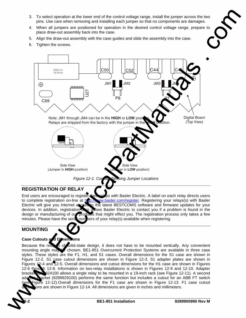
12-2 BE1-851 Installation 9289900990 Rev M
3. To select operation at the lower end of the control voltage range, install the jumper across the two pins. Use care when removing and installing each jumper so that no components are damages.
4. When all jumpers are positioned for operation in the desired control voltage range, prepare to place draw-out assembly back into the case.
5. Align the draw-out assembly with the case guides and slide the assembly into the case. 6. Tighten the screws.
Figure 12-1. Contact Sensing Jumper Locations
REGISTRATION OF RELAY End users are encouraged to register their relays with Basler Electric. A label on each relay directs users to complete registration on-line at http://www.basler.com/register. Registering your relays(s) with Basler Electric will give you Internet access to the latest BESTCOMS software and firmware updates for your devices. In addition, registration also allows Basler Electric to contact you if a problem is found in the design or manufacturing of our products that might effect you. The registration process only takes a few minutes. Please have the serial numbers of your relay(s) available when registering.
MOUNTING
Case Cutouts and Dimensions Because the relay is of solid-state design, it does not have to be mounted vertically. Any convenient mounting angle may be chosen. BE1-851 Overcurrent Protection Systems are available in three case styles. These styles are the F1, H1, and S1 cases. Overall dimensions for the S1 case are shown in Figure 12-2. S1 case cutout dimensions are shown in Figure 12-3. S1 adapter plates are shown in Figures 12-4 and 12-5. Overall dimensions and cutout dimensions for the H1 case are shown in Figures 12-6 through 12-8. Information on two-relay installations is shown in Figures 12-9 and 12-10. Adapter bracket 9289924100 allows a single relay to be mounted in a 19-inch rack (see Figure 12-11). A second adapter bracket (9289929100) performs the same function but includes a cutout for an ABB FT switch (see Figure 12-12).Overall dimensions for the F1 case are shown in Figure 12-13. F1 case cutout dimensions are shown in Figure 12-14. All dimensions are given in inches and millimeters.
www . El
ectric
alPar
tMan
uals
. com

9289900990 Rev M BE1-851 Installation 12-3
Edit Reset
Relay Minor MajorPower Trouble Alarm Alarm Trip
Overcurrent Relay
BE1-851
R
Com 0Serial Port
STYLE NUMBER:H5N1S0U
SENSING INPUTRANGE:5A PH, 5A N
POWER SUPPLY:48/125V AC/DC
SERIAL NUMBER:H00015713
P0029-0703-29-06
Figure 12-2. S1 Case, Overall Dimensions
www . El
ectric
alPar
tMan
uals
. com

12-4 BE1-851 Installation 9289900990 Rev M
Figure 12-3. S1 Case, Cutout Dimensions
www . El
ectric
alPar
tMan
uals
. com

9289900990 Rev M BE1-851 Installation 12-5
NO
TE:
DE
-BU
RR
AN
DBR
EAK
ALL
SH
AR
PE
DG
ES.
0
0
D2863-1807/22/04
CUTOUTBasler ElectricAdapter Plate
P/N 9108551022
.158
(4.0
).3
43 (8
.7)
.407
(10.
3)
5.97
0 (1
51.6
)
6.03
3 (1
53.2
)6.
218
(157
.9)
6.37
6 (1
62.0
)
.250
(6.4
)(4
PLA
CE
S)
.060
(1.5
) R4
PLA
CES
.375 (9.5)
3.935 (100.0)4.130 (104.9)
12.380 (314.5)12.565 (319.2)
16.125 (409.6)
16.500 (419.1)
Figure 12-4. S1 Case, Adapter Plate (FT32 Opening to S1 Case)
www . El
ectric
alPar
tMan
uals
. com

12-6 BE1-851 Installation 9289900990 Rev M
CUTOUT
Basler Electric Adapter Plate
P/N 9108551021
.375(9.5)
1.089(27.7)
9.339(237.2)
10.063(255.6)
10.438(265.1)
.245 (6.2) .005 DIA., C’SINK+100 DEG TO .386 (9.8) DIA.
(8 PLACES)
2.438(61.9)
8.00(203.2)
.060 (1.5) R(4 PLACES)
D2863-1707-22-04
.258
(6.6
)
6.38
1(1
62.1
)6.
640
(168
.7)
.539
(13.
7)
.290
(7.4
)
6.35
0(1
61.3
)
6.10
2(1
55.0
)0
Figure 12-5. S1 Case, Adapter Plate (S2 and FT2 Opening to S1 Case)
www . El
ectric
alPar
tMan
uals
. com

9289900990 Rev M BE1-851 Installation 12-7
Figure 12-6. H1 Case, Overall Dimensions
www . El
ectric
alPar
tMan
uals
. com
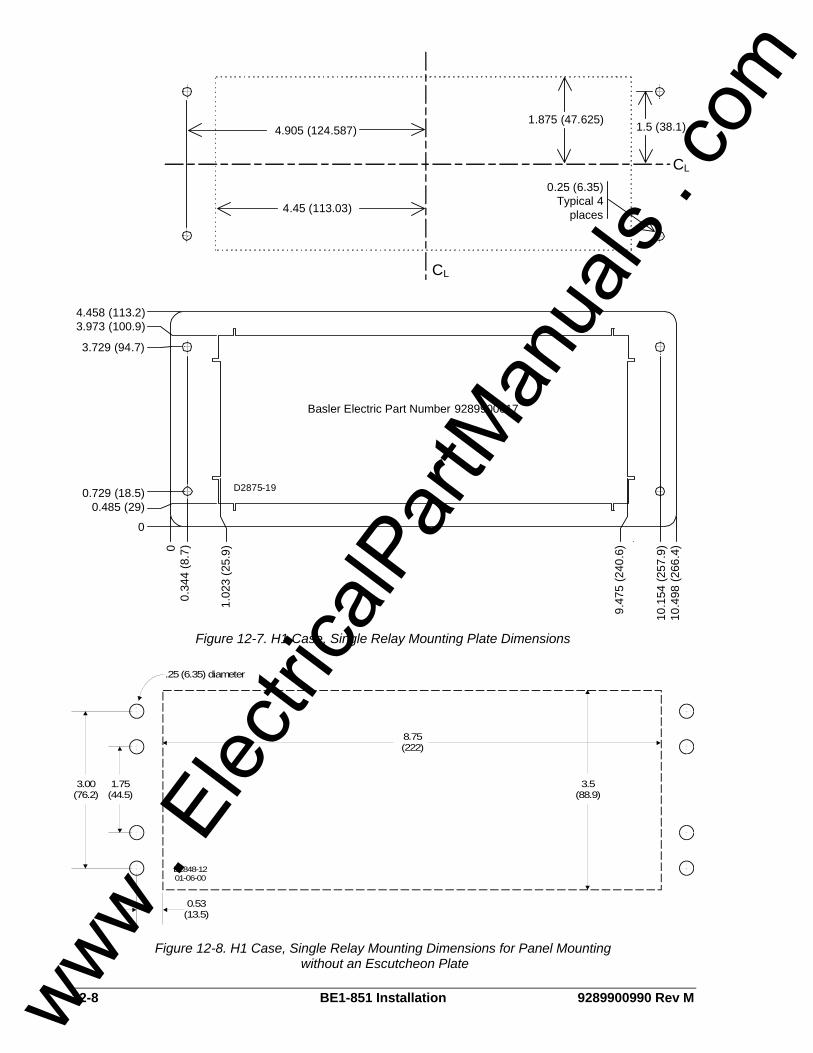
12-8 BE1-851 Installation 9289900990 Rev M
CL
CL
4.905 (124.587) 1.5 (38.1)
4.45 (113.03)
1.875 (47.625)
0.25 (6.35) Typical 4
places
4.458 (113.2)3.973 (100.9)
3.729 (94.7)
0.729 (18.5)0.485 (29)
0
00.
344
(8.7
)
1.02
3 (2
5.9)
9.47
5 (2
40.6
)
10.1
54 (2
57.9
)10
.498
(266
.4)
D2875-19
Basler Electric Part Number 9289900017
Figure 12-7. H1 Case, Single Relay Mounting Plate Dimensions
8.75(222)
1.75(44.5)
3.00(76.2)
3.5(88.9)
0.53(13.5)
.25 (6.35) diameter
D2848-1201-06-00
Figure 12-8. H1 Case, Single Relay Mounting Dimensions for Panel Mounting without an Escutcheon Plate
www . El
ectric
alPar
tMan
uals
. com
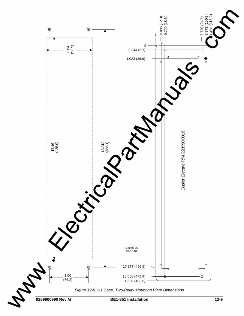
9289900990 Rev M BE1-851 Installation 12-9
C CCC
D2875-2507-15-04
3.00(76.2)
0.344 (8.7)
1.023 (26.0)
4
4
.458
(113
.)
3.97
3(1
0.0
)3.
77
2
2
99
(9.
)
0.72
9(1
8.5
)
17.977 (456.6)
18.656 (473.9)19.00 (482.6)
17.1
6(4
35.9
)
3.64
(92.
5)
0.48
5 (1
2.3)
18.3
12(4
65.1
)
Bas
ler E
lect
ric P
/N 9
2899
0001
6
Figure 12-9. H1 Case, Two-Relay Mounting Plate Dimensions
www . El
ectric
alPar
tMan
uals
. com
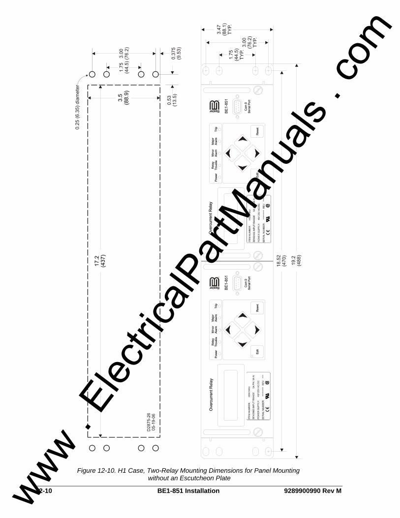
12-10 BE1-851 Installation 9289900990 Rev M
Figure 12-10. H1 Case, Two-Relay Mounting Dimensions for Panel Mounting without an Escutcheon Plate
www . El
ectric
alPar
tMan
uals
. com
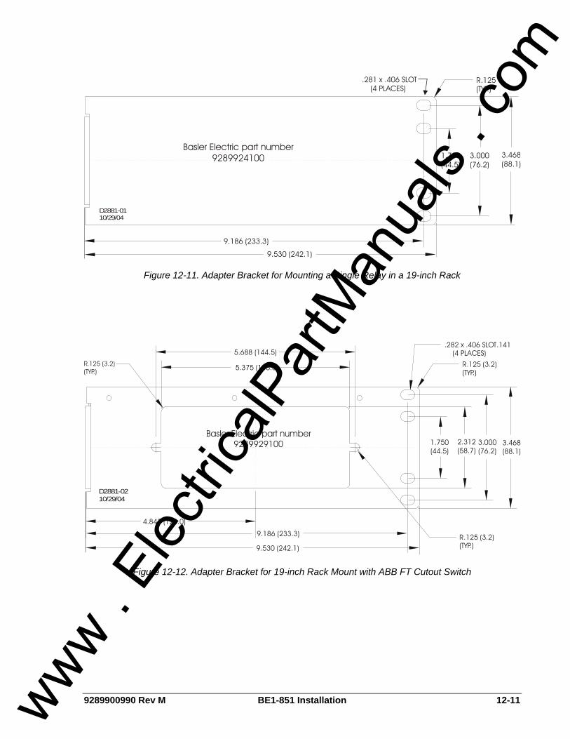
9289900990 Rev M BE1-851 Installation 12-11
9.186 (233.3)
1.750(44.5)
3.000(76.2)
9.530 (242.1)
3.468(88.1)
(TYP.)R.125.281 x .406 SLOT
(4 PLACES)
D2881-0110/29/04
Basler Electric part number9289924100
Figure 12-11. Adapter Bracket for Mounting a Single Relay in a 19-inch Rack
9.186 (233.3)
4.843 (123.0)
9.530 (242.1)
5.375 (136.5)
(TYP.)R.125 (3.2)
3.468(88.1)
3.000(76.2)
1.750(44.5)
5.688 (144.5)
(TYP.)R
2.312(58.7)
(4 PLACES).282 x .406 SLOT.141
D2881-0210/29/04
Basler Electric part number9289929100
R.125 (3.2)(TYP.)
Figure 12-12. Adapter Bracket for 19-inch Rack Mount with ABB FT Cutout Switch
www . El
ectric
alPar
tMan
uals
. com
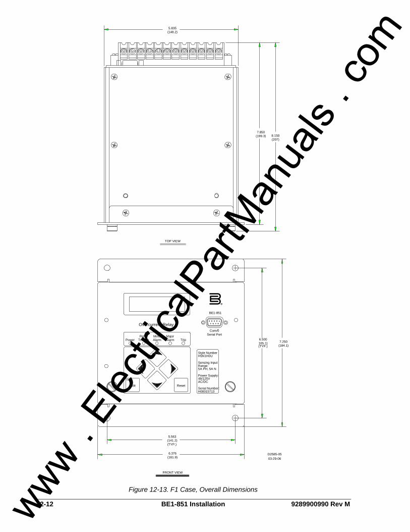
12-12 BE1-851 Installation 9289900990 Rev M
Com 0Serial Port
Edit Reset
Relay Minor MajorPower Trouble Alarm Alarm Trip
Overcurrent Relay
BE1-851
Style NumberH5N1H0U
Sensing InputRange:5A PH, 5A N
Power Supply:48/125VAC/DC
Serial Number:H00015713
5.835(148.2)
8.150(207)
7.850(199.3)
TOP VIEW
FRONT VIEW
7.250(184.1)
6.500165.1)
5.563(141.2)
6.376(161.9)
(TYP.)
(TYP.)
03-29-06D2585-05
R
Figure 12-13. F1 Case, Overall Dimensions
www . El
ectric
alPar
tMan
uals
. com

9289900990 Rev M BE1-851 Installation 12-13
2.938
5.875
(74.63)
(149.23)
6.500
3.250
(165.1)
(82.55)
2.938
5.875
(74.6)
(149.23)
2.781
5.563
(70.64)
(141.30)
LC
.250 DIA., .190-32 MOUNTINGSCREWS. (4 PLC'S)(6.35)
.125 R. (4 PLC'S)(3.18) 3-28-02
D2582-05
LC
Figure 12-14. F1 Case, Cutout Dimensions
Dovetailing Procedure Basler H1 cases can be interlocked by means of a tenon and mortise on the left and right sides of each case. The following paragraphs describe the procedure of dovetailing two cases. Figure 12-15 illustrates the process. Step 1: Remove the draw-out assembly from each case by rotating the two captive, front panel screws
counterclockwise and then sliding the assembly out of the case. Observe electrostatic discharge (ESD) precautions when handling the draw-out assemblies.
Step 2: Remove the mounting bracket from the side of each case where the two cases will mate. Each bracket is held in place by four Phillips screws.
Step 3: The rear panel must be removed from one of the cases in order for the two cases to be joined. On that panel, remove the Phillips screw from each corner of the rear panel except for the screw at the upper left-hand corner (when looking at the rear of the case). This screw is closest to Terminal Strip A.
Step 4: Turn the screw nearest to Terminal Strip A counterclockwise until the rear panel can be removed from the case. If you have difficulty removing this screw, use the alternate method described in Step 4a. Otherwise, proceed to Step 5.
Step 4a: Use a Torx® T15 driver to remove the two screws attaching Terminal Strip A to the rear panel. Remove the terminal strip and set it aside. Remove the remaining Phillips screw from the rear panel and set the rear panel aside.
Step 5: Arrange the two cases so that the rear dovetailed edge of the case without a rear panel is aligned with the front dovetailed edge of the case with the rear panel installed. Once the dovetails are aligned, slide the cases together.
Step 6: Position the rear panel on the case from which it was removed. Make sure that the panel orientation is correct. Perform Step 6a if Terminal Strip A was not removed during the disassembly process. Perform Step 6b if Terminal Strip A was removed during disassembly.
www . El
ectric
alPar
tMan
uals
. com
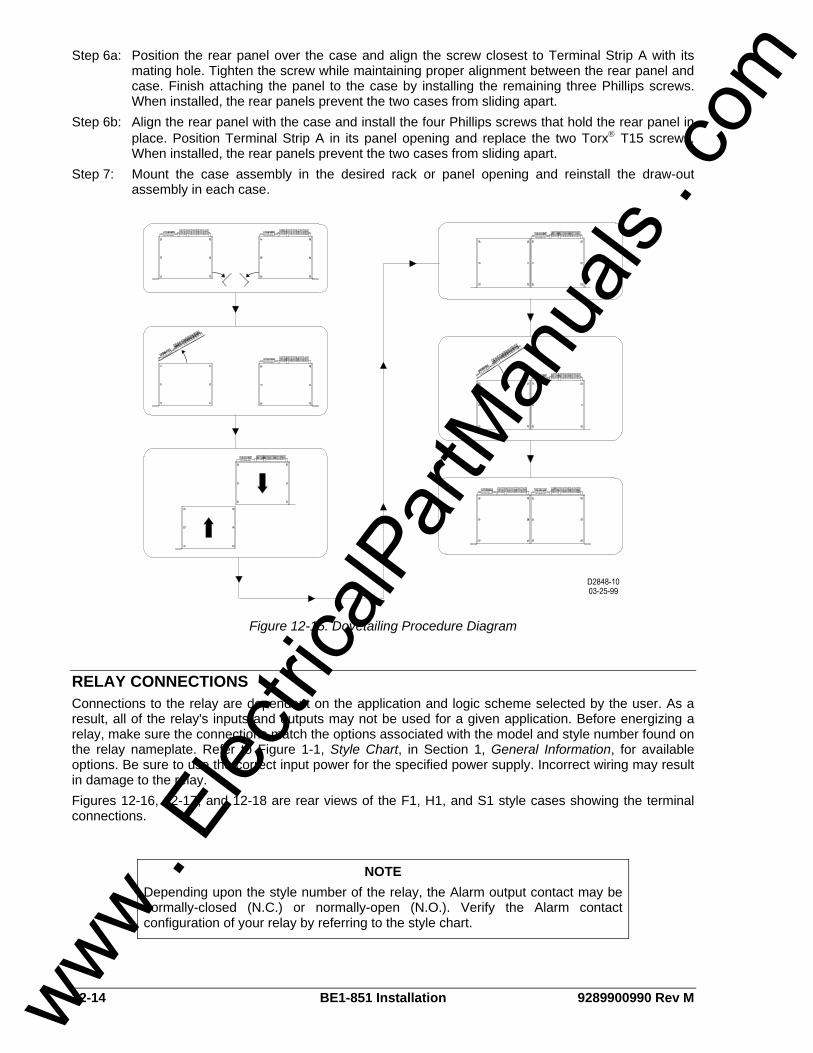
12-14 BE1-851 Installation 9289900990 Rev M
Step 6a: Position the rear panel over the case and align the screw closest to Terminal Strip A with its mating hole. Tighten the screw while maintaining proper alignment between the rear panel and case. Finish attaching the panel to the case by installing the remaining three Phillips screws. When installed, the rear panels prevent the two cases from sliding apart.
Step 6b: Align the rear panel with the case and install the four Phillips screws that hold the rear panel in place. Position Terminal Strip A in its panel opening and replace the two Torx® T15 screws. When installed, the rear panels prevent the two cases from sliding apart.
Step 7: Mount the case assembly in the desired rack or panel opening and reinstall the draw-out assembly in each case.
Figure 12-15. Dovetailing Procedure Diagram
RELAY CONNECTIONS Connections to the relay are dependent on the application and logic scheme selected by the user. As a result, all of the relay's inputs and outputs may not be used for a given application. Before energizing a relay, make sure the connections match the options associated with the model and style number found on the relay nameplate. Refer to Figure 1-1, Style Chart, in Section 1, General Information, for available options. Be sure to use the correct input power for the specified power supply. Incorrect wiring may result in damage to the relay. Figures 12-16, 12-17, and 12-18 are rear views of the F1, H1, and S1 style cases showing the terminal connections.
NOTE Depending upon the style number of the relay, the Alarm output contact may be normally-closed (N.C.) or normally-open (N.O.). Verify the Alarm contact configuration of your relay by referring to the style chart.
www . El
ectric
alPar
tMan
uals
. com
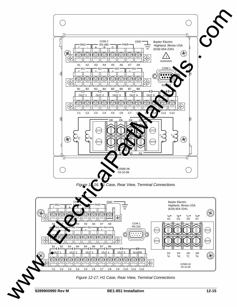
9289900990 Rev M BE1-851 Installation 12-15
A4 A5A1 A2 A3 A6 A7 A8
-IN1
+ +IN2
- +IN3
- -IN4
+
IRIG+ -
PWRCA B
RS-485GNDCOM 2
(618) 654-2341Highland, Illinois USA Basler Electric
COM 1
RS-232
!WARNING
B8B7B1 B2 B3 B4 B5 B6
OUT 2 OUT 3 OUT 4 OUT 5 ALARMOUT 1
C12C11C10C9C8C7C6C5C4C3C2C1
D2D4D6D8
INCI AI IB
D1D3D5D7
D2585-0603-10-06
Figure 12-16. F1 Case, Rear View, Terminal Connections
I I
INICI BIA
NCBA II
D2 D4 D6 D8
D7D5D3D1
IRIG+ -
PWRCA B
RS-485
A4 A5A1 A2 A3 A6 A7 A8
B8B7B1 B2 B3 B4 B5 B6
C12C11C10C9C8C7C6C5C4C3C2C1
COM 1
GND
-IN1
+ +IN2
- +IN3
- -IN4
+
OUT 2 OUT 3 OUT 4 OUT 5 ALARMOUT 1
COM 2
RS-232
(618) 654-2341Highland, Illinois USABasler Electric
D2583-0203-10-06
Figure 12-17. H1 Case, Rear View, Terminal Connections
www . El
ectric
alPar
tMan
uals
. com
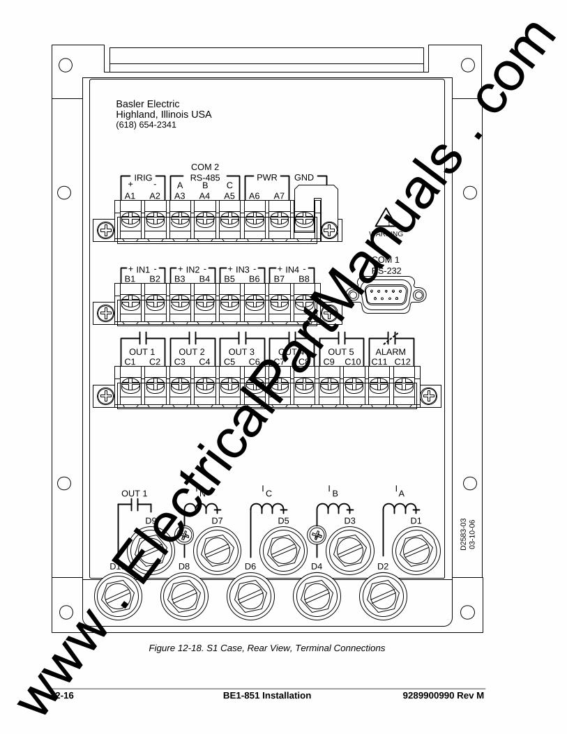
12-16 BE1-851 Installation 9289900990 Rev M
D2D4D6D8D10
D9 D7 D5 D3 D1
AII BI COUT 1 I N
C1 C2 C3 C4 C5 C6 C7 C8 C9 C10 C11 C12OUT 2 OUT 3 OUT 4 OUT 5 ALARM
-+ IN1B8B7B6B5B4B3B2B1
IN2+ - IN3+ - IN4+ -
RS-485BA C
PWR-+
IRIG
A1 A2 A3 A4 A5 A6 A7
RS-232
WARNING!
GND
OUT 1
Highland, Illinois USABasler Electric
(618) 654-2341
COM 2
COM 1
D25
83-0
303
-10-
06
Figure 12-18. S1 Case, Rear View, Terminal Connections
www . El
ectric
alPar
tMan
uals
. com

9289900990 Rev M BE1-851 Installation 12-17
Typical DC and AC Connections Typical external DC and AC connections for the BE1-851 are shown in Figures 12-19 and 12-20.
A
B
C
BREAKER
A B C
LINE
D1 D2
D4D3
D5 D6
D8 D7
03-09-00D2569-04
Figure 12-19. Typical AC Connection Diagram
www . El
ectric
alPar
tMan
uals
. com

12-18 BE1-851 Installation 9289900990 Rev M
Figure 12-20. Typical DC Connection Diagram
www . El
ectric
alPar
tMan
uals
. com

9289900990 Rev M BE1-851 Installation 12-19
Terminal Blocks There are two sizes of terminal blocks used on the H1 case design, the current circuit block and the input-output blocks. The current circuit terminal block is the larger of the two types and uses 8/32 inch Phillips head screws with lock washers. The input-output block is the smaller of the two types and uses 6/32 inch slot or Phillips head screws with no washer. The S1 case design uses slotted 10-32 washerless "pan-head" screws for current inputs. The input-output blocks are the same size as those incorporated in the H1 design, and use 6/32-inch slot or Phillips head screws. As stated, the current circuit terminal block on the H1 case uses 8/32 inch Phillips head screws with lock washers. The lock washer is an integral part of the current circuit wiring system and should not be removed. Without the lock washer, the 8/32-inch screw may bottom out, preventing a tight fit against the lug (screw feels tight but lug may move under the screw head). The maximum wire lug width accommodated by the current circuit terminal block on the H1 case is .344 inches (8.6 mm). The maximum wire lug width accommodated by the input-output block on the H1 and S1 case is 0.320 inches (8.1 mm). Current inputs on the S1 case are not limited by the barrier board terminal block design.
SETTINGS
The settings for your application need to be entered and confirmed prior to placing the relay in service. Register settings such as breaker duty can be entered to match the current state of your system.
PREPARING THE RELAY FOR SERVICE Basler microprocessor-based protection systems are similar in nature to a panel of electromechanical or solid-state component relays. Both must be wired together with inputs and outputs, and have operating settings applied. Logic settings determine which protection elements are electronically wired to the inputs and outputs of the device. Operating settings determine the pickup thresholds and time delays. The logic and operating settings should be tested by applying actual inputs and operating quantities and verifying proper output response. For more details, refer to Section 13, Testing and Maintenance. All of the following connections and functions should be verified during commissioning tests:
• Proper connection and sensing of current and voltage signals • Input and output contact connections • I/O sensing versus virtual sensing • Settings validation • Proper operation of equipment (main or auxiliary) • Proper alarming (to SCADA) and/or targeting
Refer to Section 7, BESTlogic Programmable Logic, for information about customizing preprogrammed logic and creating user-defined logic, and Section 8, Application, for information about the application of preprogrammed logic schemes.
COMMUNICATION CONNECTIONS
Front/Rear RS-232 Connectors Front and rear RS-232 connectors are DB-9 female DCE connectors. Connector pin numbers, functions, names, and signal directions are shown in Table 12-2. Figures 12-21 through 12-23 provide RS-232 cable connection diagrams.
NOTE Except as noted, connections to the relay should be made with a minimum wire size of #14 AWG.
www . El
ectric
alPar
tMan
uals
. com
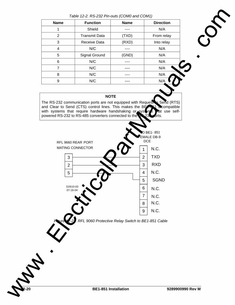
12-20 BE1-851 Installation 9289900990 Rev M
Table 12-2. RS-232 Pin-outs (COM0 and COM1)
Name Function Name Direction 1 Shield ---- N/A
2 Transmit Data (TXD) From relay
3 Receive Data (RXD) Into relay
4 N/C ---- N/A
5 Signal Ground (GND) N/A
6 N/C ---- N/A
7 N/C ---- N/A
8 N/C ---- N/A
9 N/C ---- N/A
5
2
3
MATING CONNECTOR
FEMALE DB-9DCE
07-16-04D2610-03
RFL 9660 REAR PORT
TO BE1- 851
1
2
3
4
5
TXD
RXD
N.C.
SGND
9
6
7
8
N.C.
N.C.
N.C.N.C.
N.C.
Figure 12-21. RFL 9060 Protective Relay Switch to BE1-851 Cable
NOTE The RS-232 communication ports are not equipped with Request to Send (RTS) and Clear to Send (CTS) control lines. This makes the BE1-851 incompatible with systems that require hardware handshaking or systems that use self-powered RS-232 to RS-485 converters connected to the RS-232 ports.
www . El
ectric
alPar
tMan
uals
. com
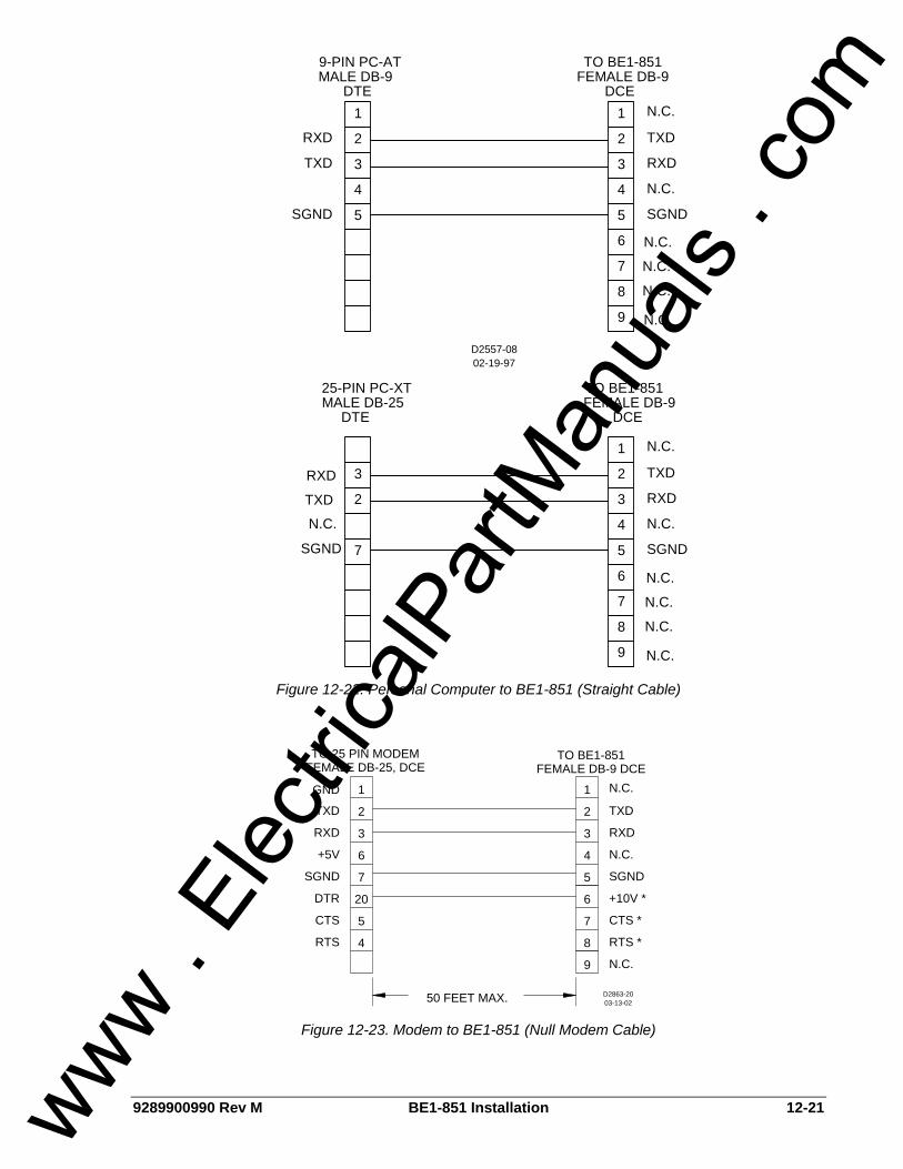
9289900990 Rev M BE1-851 Installation 12-21
5
4
3
2
1 1
2
3
4
5
RXD
TXD
SGND
TXD
RXD
N.C.
SGND
FEMALE DB-9MALE DB-9
02-19-97D2557-08
9
6
7
8
N.C.
N.C.
TO BE1-8519-PIN PC-AT
25-PIN PC-XT TO BE1-851
N.C.
8
7
6
9
MALE DB-25 FEMALE DB-9
SGND
N.C.
RXD
TXD
5
4
3
2
1
3
2
7
N.C.
N.C.
N.C.
N.C.
N.C.
N.C.
N.C.
N.C.
DTE DCE
DCEDTE
RXD
TXD
SGND
Figure 12-22. Personal Computer to BE1-851 (Straight Cable)
4
5
20
7
6
3
2
1 1
2
3
4
5
TXD
RXD
+5V
SGND
TXD
RXD
N.C.
SGND
50 FEET MAX.
FEMALE DB-9 DCEFEMALE DB-25, DCE
03-13-02D2863-20
RTS
CTS
DTR
9
6
7
8 RTS *
CTS *
+10V *
N.C.
N.C.GND
TO BE1-851TO 25 PIN MODEM
Figure 12-23. Modem to BE1-851 (Null Modem Cable)
www . El
ectric
alPar
tMan
uals
. com

12-22 BE1-851 Installation 9289900990 Rev M
RS-485 Connector The RS-485 connector is a three-position terminal block connector designed to interface to a standard communication cable. A twisted-pair cable is recommended. Connector pin numbers, functions, names, and signal directions are shown in Table 12-3. A cable connection diagram is provided in Figure 12-24.
Table 12-3. RS-485 Pin-outs (COM2) Terminal Function Name Direction
A Send/Receive A (SDA/RDA) In/Out B Send/Receive B (SDB/RDB) In/Out C Signal Ground (GND) N/A
02-20-97D2557-11
22
6
4
A
B
C
3 POSITION TBDB-37 FEMALETO BE1-851TO RS422/RS485
19
24
CB
A
A
B
C
4000'MAX
.
COM 2BE1-851
BE1-851COM 2
BE1-851COM 2
Rt
tR
R = OPTIONAL TERMINATINGtRESISTOR (120 OHMS TYP.)
A3
A4A5
A3
A4
A5
A3
A4
A5
Figure 12-24. RS-485 DB-37 to BE1-851
IRIG Input and Connections The IRIG input is fully isolated and supports IRIG Standard 200-98, Format B002. The demodulated (dc level-shifted) input signal must be 3.5 volts or higher to be recognized as a high logic level. The maximum acceptable input voltage range is +10 to –10 volts. Input burden is nonlinear and rated at approximately 4kΩ at 3.5Vdc and approximately 3kΩ at 20Vdc. IRIG connections are located on a terminal block shared with the RS-485 and input power terminals. Terminal designations and functions are shown in Table 12-4.
Table 12-4. IRIG Pin-outs
Terminal Function
A1 (+) Signal
A2 (-) Reference
www . El
ectric
alPar
tMan
uals
. com
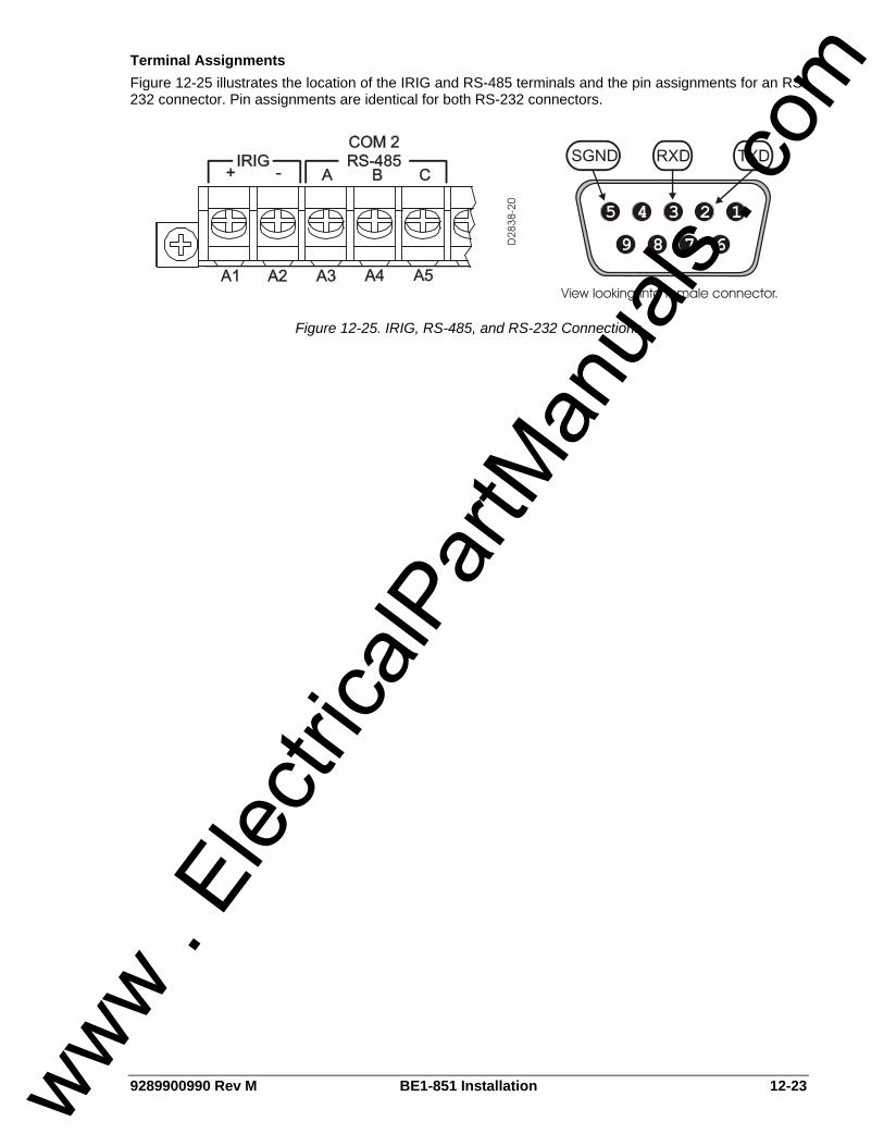
9289900990 Rev M BE1-851 Installation 12-23
Terminal Assignments Figure 12-25 illustrates the location of the IRIG and RS-485 terminals and the pin assignments for an RS-232 connector. Pin assignments are identical for both RS-232 connectors.
Figure 12-25. IRIG, RS-485, and RS-232 Connections
www . El
ectric
alPar
tMan
uals
. com

12-24 BE1-851 Installation 9289900990 Rev M
This page intentionally left blank.
www . El
ectric
alPar
tMan
uals
. com
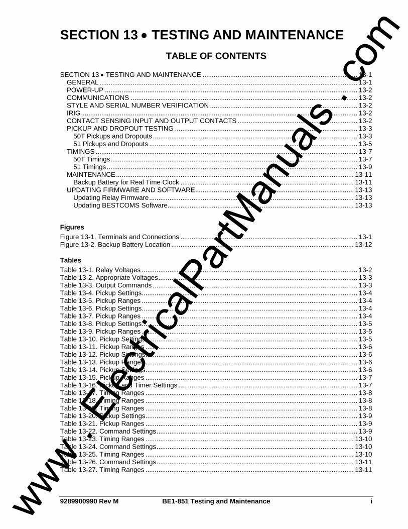
9289900990 Rev M BE1-851 Testing and Maintenance i
SECTION 13 • TESTING AND MAINTENANCE TABLE OF CONTENTS
SECTION 13 • TESTING AND MAINTENANCE .................................................................................... 13-1
GENERAL............................................................................................................................................ 13-1 POWER-UP ......................................................................................................................................... 13-2 COMMUNICATIONS ........................................................................................................................... 13-2 STYLE AND SERIAL NUMBER VERIFICATION ................................................................................ 13-2 IRIG...................................................................................................................................................... 13-2 CONTACT SENSING INPUT AND OUTPUT CONTACTS ................................................................. 13-2 PICKUP AND DROPOUT TESTING ................................................................................................... 13-3
50T Pickups and Dropouts ............................................................................................................... 13-3 51 Pickups and Dropouts ................................................................................................................. 13-5
TIMINGS .............................................................................................................................................. 13-7 50T Timings...................................................................................................................................... 13-7 51 Timings........................................................................................................................................ 13-9
MAINTENANCE................................................................................................................................. 13-11 Backup Battery for Real Time Clock .............................................................................................. 13-11
UPDATING FIRMWARE AND SOFTWARE...................................................................................... 13-13 Updating Relay Firmware............................................................................................................... 13-13 Updating BESTCOMS Software..................................................................................................... 13-13
Figures Figure 13-1. Terminals and Connections ................................................................................................ 13-1 Figure 13-2. Backup Battery Location ................................................................................................... 13-12
Tables Table 13-1. Relay Voltages ..................................................................................................................... 13-2 Table 13-2. Appropriate Voltages............................................................................................................ 13-3 Table 13-3. Output Commands ............................................................................................................... 13-3 Table 13-4. Pickup Settings..................................................................................................................... 13-4 Table 13-5. Pickup Ranges ..................................................................................................................... 13-4 Table 13-6. Pickup Settings..................................................................................................................... 13-4 Table 13-7. Pickup Ranges ..................................................................................................................... 13-4 Table 13-8. Pickup Settings..................................................................................................................... 13-5 Table 13-9. Pickup Ranges ..................................................................................................................... 13-5 Table 13-10. Pickup Settings................................................................................................................... 13-5 Table 13-11. Pickup Ranges ................................................................................................................... 13-6 Table 13-12. Pickup Settings................................................................................................................... 13-6 Table 13-13. Pickup Ranges ................................................................................................................... 13-6 Table 13-14. Pickup Settings................................................................................................................... 13-6 Table 13-15. Pickup Ranges ................................................................................................................... 13-7 Table 13-16. Pickup and Timer Settings ................................................................................................. 13-7 Table 13-17. Timing Ranges ................................................................................................................... 13-8 Table 13-18. Timing Ranges ................................................................................................................... 13-8 Table 13-19. Timing Ranges ................................................................................................................... 13-8 Table 13-20. Pickup Settings................................................................................................................... 13-9 Table 13-21. Pickup Ranges ................................................................................................................... 13-9 Table 13-22. Command Settings............................................................................................................. 13-9 Table 13-23. Timing Ranges ................................................................................................................. 13-10 Table 13-24. Command Settings........................................................................................................... 13-10 Table 13-25. Timing Ranges ................................................................................................................. 13-10 Table 13-26. Command Settings........................................................................................................... 13-11 Table 13-27. Timing Ranges ................................................................................................................. 13-11
www . El
ectric
alPar
tMan
uals
. com

ii BE1-851 Testing and Maintenance 9289900990 Rev M
This page intentionally left blank.
www . El
ectric
alPar
tMan
uals
. com

9289900990 Rev M BE1-851 Testing and Maintenance 13-1
SECTION 13 • TESTING AND MAINTENANCE GENERAL You may prefer to test your relay before installation. To verify functionality of the BE1-851 relay, perform the procedures provided in the following paragraphs. A relay terminals and connections diagram is provided in Figure 13-1.
A1 A2 A3 A4 A5 A6 A7 A8
C1
C2
C3
C4
C5
C6
C7
C8
C9
C10
C11
C12
D1 D2 D3 D4 D5 D6 D7 D8
B7
B8
B4
B5
B6
B2
B3
B1
+ - A B C
IRIGRS-485 PWR
INPUT
CHAS.
GND
D2518-0303-10-06
Figure 13-1. Terminals and Connections
www . El
ectric
alPar
tMan
uals
. com

13-2 BE1-851 Testing and Maintenance 9289900990 Rev M
POWER-UP Step 1: Apply voltage to Power Terminals A6 and A7. Table 13-1 shows the appropriate voltage for
each style of relay.
Table 13-1. Relay Voltages
Style Number Voltage Input
xxx1xxx 48-125 Vac/dc
xxx2xxx 125-250 Vac/dc
xxx3xxx 24 Vdc
Step 2: Verify that the Power LED is illuminated, the display backlight is lit, and characters are
displayed on the display. Upon power-up of the relay, a brief self-test is performed. During this five-second test, all of the front panel LEDs will flash and the display will indicate each step of the test followed by a screen showing the relay model number and software version.
COMMUNICATIONS Either a VT-100 terminal or a computer with a serial port and suitable communications software may be used to communicate with any of the BE1-851 relay's three communications ports. The relay default communications settings are: a baud rate of 9600, 8 data bits, 1 stop bit, parity - none and Xon/Xoff flow control. Step 1: Connect the terminal cable to the rear RS-232 port on the relay. Step 2: Transmit the command “ACCESS=851” to the relay. The relay should respond with
“ACCESS GRANTED: GLOBAL”. Transmit “EXIT” after getting access. Step 3: Connect the terminal cable to the front RS-232 port on the relay. Step 4: Transmit the command “ACCESS=851” to the relay. The relay should respond with
“ACCESS GRANTED: GLOBAL”. Transmit “EXIT” after getting access. Step 5: Connect an RS-232/RS485 converter box to the RS-232 port on the terminal. Connect the
RS-485 output terminals of the converter box to the relay RS-485 terminals. Step 6: Transmit the command “ACCESS=851” to the relay. The relay should respond with
“ACCESS GRANTED: GLOBAL”. Transmit “EXIT” after getting access.
STYLE AND SERIAL NUMBER VERIFICATION Over any communications port, transmit the command "RG-VER." The BE1-851 will respond with the model number, style number, program version and date, boot code version and date, as well as the relay serial number. Verify that the part, style, and serial numbers match the information on the relay front label.
IRIG Step 1: Connect a suitable IRIG source to the relay IRIG Terminals A1 and A2. Step 2: Upon receiving the IRIG signal, the relay clock will be set with the current time, month, and
day. This may be verified at Screen 4.5 on the front panel display or by transmitting “RG-TIME” and “RG-DATE” to any of the relay communications ports.
CONTACT SENSING INPUT AND OUTPUT CONTACTS Step 1: Apply voltage to the relay contact sensing inputs IN1, IN2, IN3, and IN4. Table 13-2 shows
the appropriate voltage to apply.
www . El
ectric
alPar
tMan
uals
. com

9289900990 Rev M BE1-851 Testing and Maintenance 13-3
Table 13-2. Appropriate Voltages
Style Number Input Voltage
xxx1xxx 48 Vdc
xxx2xxx 125 Vdc
xxx3xxx 24 Vdc
Step 2: Transmit the command “RG-STAT”. Examine response line “INPUT(1-4) STATUS:” to verify
that all inputs were detected. Step 3: Transmit the commands “ACCESS=851”, “CS-OUT=ENA”, “CO-OUT=ENA”, and “EXIT;Y” to
enable the output control override capability of the relay. Step 4: Using Table 13-3 as a guide, transmit the commands listed and verify that the appropriate
output contacts change state. When each command is transmitted, the corresponding output will be pulsed briefly. An ohmmeter or continuity tester may be used to monitor the output contact status.
Table 13-3. Output Commands
Output Terminals Commands
OUT1 (N.O.) C1 & C2 CS-OUT1=P;CO-OUT1=P
OUT2 (N.O.) C3 & C4 CS-OUT2=P;CO-OUT2=P
OUT3 (N.O.) C5 & C6 CS-OUT3=P;CO-OUT3=P
OUT4 (N.O.) C7 & C8 CS-OUT4=P;CO-OUT4=P
OUT5 (N.O.) C9 & C10 CS-OUT5=P;CO-OUT5=P
ALARM (N.C.) ∗ C11 & C12 CS-OUTA=P;CO-OUTA=P
ALARM (N.O.) ∗ C11 & C12 CS-OUTA=P;CO-OUTA=P
∗ The style number determines if the ALARM output is N.C. or N.O. See Section 1, General Information, Model and Style Number Description. Step 5: Disable the control override ability if desired by transmitting the commands “ACCESS=851”,
“CS-OUT=DIS”, “CO-OUT=DIS”, and “EXIT;Y” to the relay.
PICKUP AND DROPOUT TESTING Transmit the frequency command, “SG-FREQ=50” or “SG-FREQ=60”, depending on which frequency the relay is to be tested at. Transmit the commands “ACCESS=851”, CS-GROUP=0”, and “CO-GROUP=0” to select settings group 0. Save the settings by transmitting the command “EXIT;Y”.
50T Pickups and Dropouts Step 1: Transmit the following scheme to the relay: ACCESS=851 SL-N=NONE YES SL-N=PU50 SL-50T=1,0 SL-VO1=50TPT+50TNT EXIT;Y Step 2: Transmit the appropriate command from Table 13-4 to program the 50T pickup setting.
www . El
ectric
alPar
tMan
uals
. com

13-4 BE1-851 Testing and Maintenance 9289900990 Rev M
Table 13-4. Pickup Settings
Commands Style Number
Phase Neutral
x1xxxxx S0-50TP=0.1A,0m S0-50TN=0.1A,0m
x3xxxxx S0-50TP=0.5A,0m S0-50TN=0.1A,0m
x5xxxxx S0-50TP=0.5A,0m S0-50TN=0.5A,0m
Step 3: Slowly ramp up the current applied at Phase A input until OUT1 closes. Verify that pickup
occurred within the acceptable range listed in Table 13-5.
Table 13-5. Pickup Ranges
Phase Neutral Style Number Low Limit High Limit Low Limit High Limit
x1xxxxx 0.09 amps 0.11 amps 0.09 amps 0.11 amps
x3xxxxx 0.45 amps 0.55 amps 0.09 amps 0.11 amps
x5xxxxx 0.45 amps 0.55 amps 0.45 amps 0.55 amps
Step 4: After pickup occurs, ramp the current down slowly until OUT1 opens. Dropout should occur
at 90% ±2% of the pickup current magnitude. Step 5: Transmit the appropriate command in Table 13-6 to reprogram the pickup setting.
Table 13-6. Pickup Settings
Commands Style Number
Phase Neutral
x1xxxxx S0-50TP=1.0A,0m S0-50TN=1.0A,0m
x3xxxxx S0-50TP=5.0A,0m S0-50TN=1.0A,0m
x5xxxxx S0-50TP=5.0A,0m S0-50TN=5.0A,0m
Step 6: Slowly ramp up the current applied at the relay Phase A input until OUT1 closes. Verify that
pickup occurred within the acceptable range listed in Table 13-7.
Table 13-7. Pickup Ranges
Phase Neutral Style Number Low Limit High Limit Low Limit High Limit
x1xxxxx 0.98 amps 1.02 amps 0.98 amps 1.02 amps
x3xxxxx 4.9 amps 5.1 amps 0.98 amps 1.02 amps
x5xxxxx 4.9 amps 5.1 amps 4.9 amps 5.1 amps
Step 7: After pickup occurs, ramp the current down slowly until OUT1 opens. Dropout should occur
at 90% ±2% of the pickup current magnitude. Step 8: Transmit the appropriate command in Table 13-8 to reprogram the pickup setting.
www . El
ectric
alPar
tMan
uals
. com

9289900990 Rev M BE1-851 Testing and Maintenance 13-5
Table 13-8. Pickup Settings
Commands Style Number
Phase Neutral
x1xxxxx S0-50TP=5.0A,0m S0-50TN=5.0A,0m
x3xxxxx S0-50TP=25.0A,0m S0-50TN=5.0A,0m
x5xxxxx S0-50TP=25.0A,0m S0-50TN=25.0A,0m
Step 9: Slowly ramp up the current applied at the relay Phase A input until OUT1 closes. Verify that
pickup occurred within the acceptable range listed in Table 13-9.
Table 13-9. Pickup Ranges
Phase Neutral Style Number Low Limit High Limit Low Limit High Limit
x1xxxxx 4.9 amps 5.1 amps 4.9 amps 5.1 amps
x3xxxxx 24.5 amps 25.5 amps 4.9 amps 5.1 amps
x5xxxxx 24.5 amps 25.5 amps 24.5 amps 25.5 amps
Step 10: After pickup occurs, ramp the current down slowly until OUT1 opens. Dropout should occur at 90% ±2% of the pickup current magnitude.
Step 11: Repeat Steps 2 through 10 for the Phase B current input.
Step 12: Repeat Steps 2 through 10 for the Phase C current input.
Step 13: Repeat Steps 2 through 10 for the Neutral current input.
51 Pickups and Dropouts Step 1: Transmit the following scheme to the relay: ACCESS=851 SL-N=NONE YES SL-N=PU51 SL-51=1,0 SL-VO1=51PT+51NT EXIT;Y
Step 2: Transmit the appropriate command in Table 13-10 to program the pickup setting.
Table 13-10. Pickup Settings
Commands Style Number
Phase Neutral
x1xxxxx S0-51P=0.1A,0m S0-51N=0.1A,0m
x3xxxxx S0-51P=0.5A,0m S0-51N=0.1A,0m
x5xxxxx S0-51P=0.5A,0m S0-51N=0.5A,0m
www . El
ectric
alPar
tMan
uals
. com
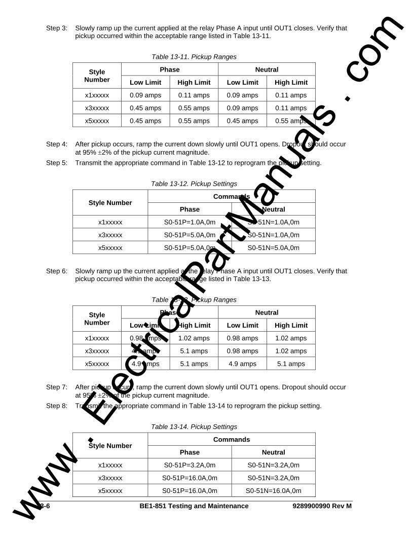
13-6 BE1-851 Testing and Maintenance 9289900990 Rev M
Step 3: Slowly ramp up the current applied at the relay Phase A input until OUT1 closes. Verify that pickup occurred within the acceptable range listed in Table 13-11.
Table 13-11. Pickup Ranges
Phase Neutral Style Number Low Limit High Limit Low Limit High Limit
x1xxxxx 0.09 amps 0.11 amps 0.09 amps 0.11 amps
x3xxxxx 0.45 amps 0.55 amps 0.09 amps 0.11 amps
x5xxxxx 0.45 amps 0.55 amps 0.45 amps 0.55 amps
Step 4: After pickup occurs, ramp the current down slowly until OUT1 opens. Dropout should occur
at 95% ±2% of the pickup current magnitude. Step 5: Transmit the appropriate command in Table 13-12 to reprogram the pickup setting.
Table 13-12. Pickup Settings
Commands Style Number
Phase Neutral
x1xxxxx S0-51P=1.0A,0m S0-51N=1.0A,0m
x3xxxxx S0-51P=5.0A,0m S0-51N=1.0A,0m
x5xxxxx S0-51P=5.0A,0m S0-51N=5.0A,0m
Step 6: Slowly ramp up the current applied at the relay Phase A input until OUT1 closes. Verify that
pickup occurred within the acceptable range listed in Table 13-13.
Table 13-13. Pickup Ranges
Phase Neutral Style Number Low Limit High Limit Low Limit High Limit
x1xxxxx 0.98 amps 1.02 amps 0.98 amps 1.02 amps
x3xxxxx 4.9 amps 5.1 amps 0.98 amps 1.02 amps
x5xxxxx 4.9 amps 5.1 amps 4.9 amps 5.1 amps
Step 7: After pickup occurs, ramp the current down slowly until OUT1 opens. Dropout should occur
at 95% ±2% of the pickup current magnitude. Step 8: Transmit the appropriate command in Table 13-14 to reprogram the pickup setting.
Table 13-14. Pickup Settings
Commands Style Number
Phase Neutral
x1xxxxx S0-51P=3.2A,0m S0-51N=3.2A,0m
x3xxxxx S0-51P=16.0A,0m S0-51N=3.2A,0m
x5xxxxx S0-51P=16.0A,0m S0-51N=16.0A,0m
www . El
ectric
alPar
tMan
uals
. com

9289900990 Rev M BE1-851 Testing and Maintenance 13-7
Step 9: Slowly ramp up the current applied at the relay Phase A input until OUT1 closes. Verify that pickup occurred within the acceptable range listed in Table 13-15.
Table 13-15. Pickup Ranges
Phase Neutral Style Number Low Limit High Limit Low Limit High Limit
x1xxxxx 3.136 amps 3.264 amps 3.136 amps 3.264 amps
x3xxxxx 15.68 amps 16.32 amps 3.136 amps 3.264 amps
x5xxxxx 15.68 amps 16.32 amps 15.68 amps 16.32 amps
Step 10: After pickup occurs, ramp the current down slowly until OUT1 opens. Dropout should occur
at 95% ±2% of the pickup current magnitude.
Step 11: Repeat Steps 2 through 10 for the Phase B current input.
Step 12: Repeat Steps 2 through 10 for the Phase C current input.
Step 13: Repeat Steps 2 through 10 for the Neutral current input.
TIMINGS
50T Timings Step 1: Transmit the following scheme to the relay: ACCESS=851 SL-N=NONE YES SL-N=TIME50 SL-50T=1,0 SL-VO1=50TPT+50TNT SG-DSP=F EXIT;Y Step 2: Transmit the appropriate command in Table 13-16 to program the pickup and timer settings.
Table 13-16. Pickup and Timer Settings
Commands Style Number
Phase Neutral
x1xxxxx S0-50TP=1.0A,0.0m S0-50TN=1.0A,0.0m
x3xxxxx S0-50TP=5.0A,0.0m S0-50TN=1.0A,0.0m
x5xxxxx S0-50TP=5.0A,0.0m S0-50TN=5.0A,0.0m
Step 3: Apply the appropriate current value to the Phase A input and measure the time between the
application of current and OUT1 closing. Verify that the timing is within the acceptance range stated in Table 13-17.
www . El
ectric
alPar
tMan
uals
. com

13-8 BE1-851 Testing and Maintenance 9289900990 Rev M
Table 13-17. Timing Ranges
Current/Frequency Timing Range Style Number Phase Neutral Low Limit High Limit
x1xxxxx 1.05A/50 Hz 1.05A/50 Hz 0.0 sec 0.1 sec
x1xxxxx 1.05A/60 Hz 1.05A/60 Hz 0.0 sec 0.083 sec
x3xxxxx 5.25A/50 Hz 1.05A/50 Hz 0.0 sec 0.1 sec
x3xxxxx 5.25A/60 Hz 1.05A/60 Hz 0.0 sec 0.083 sec
x5xxxxx 5.25A/50 Hz 5.25A/50 Hz 0.0 sec 0.1 sec
x5xxxxx 5.25A/60 Hz 5.25A/60 Hz 0.0 sec 0.083 sec
Step 4: Apply the appropriate current value to the Phase A input and measure the time between the
application of current until OUT1 closes. Verify that the timing is within the acceptance range stated in Table 13-18.
Table 13-18. Timing Ranges
Current/Frequency Timing Range Style Number Phase Neutral Low Limit High Limit
x1xxxxx 1.5A/50 Hz 1.5A/50 Hz 0.0 sec 0.04 sec
x1xxxxx 1.5A/60 Hz 1.5A/60 Hz 0.0 sec 0.033 sec
x3xxxxx 7.5A/50 Hz 1.5A/50 Hz 0.0 sec 0.04 sec
x3xxxxx 7.5A/60 Hz 1.5A/60 Hz 0.0 sec 0.033 sec
x5xxxxx 7.5A/50 Hz 7.5A/50 Hz 0.0 sec 0.04 sec
x5xxxxx 7.5A/60 Hz 7.5A/60 Hz 0.0 sec 0.033 sec
Step 5: Apply the appropriate current value to the Phase A input and measure the time between the
application of current and OUT1 closing. Verify that the timing is within the acceptance range stated in Table 13-19.
Table 13-19. Timing Ranges
Current/Frequency Timing Range Style Number Phase Neutral Low Limit High Limit
x1xxxxx 5.0A/50 Hz 5.0A/50 Hz 0.0 sec 0.025 sec
x1xxxxx 5.0A/60 Hz 5.0A/60 Hz 0.0 sec 0.021 sec
x3xxxxx 25.0A/50 Hz 5.0A/50 Hz 0.0 sec 0.025 sec
x3xxxxx 25.0A/60 Hz 5.0A/60 Hz 0.0 sec 0.021 sec
x5xxxxx 25.0A/50 Hz 25.0A/50 Hz 0.0 sec 0.025 sec
x5xxxxx 25.0A/60 Hz 25.0A/60 Hz 0.0 sec 0.021 sec
Step 6: Transmit the appropriate command in Table 13-20 to program the pickup setting.
www . El
ectric
alPar
tMan
uals
. com
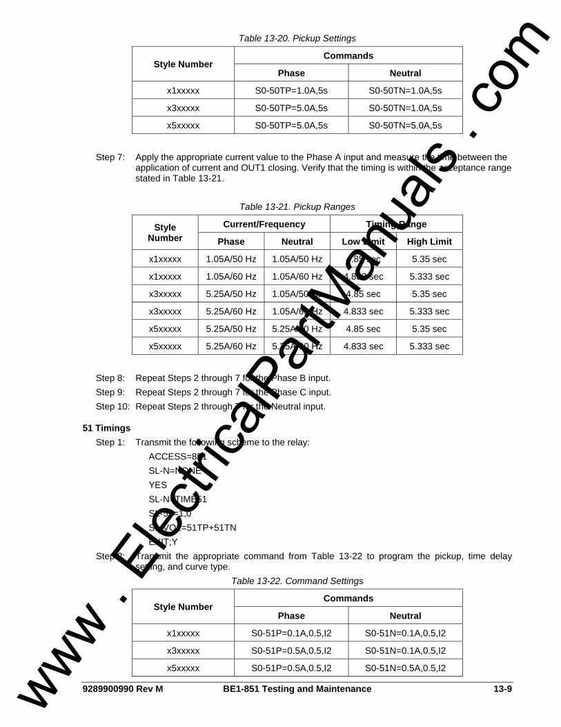
9289900990 Rev M BE1-851 Testing and Maintenance 13-9
Table 13-20. Pickup Settings
Commands Style Number
Phase Neutral
x1xxxxx S0-50TP=1.0A,5s S0-50TN=1.0A,5s
x3xxxxx S0-50TP=5.0A,5s S0-50TN=1.0A,5s
x5xxxxx S0-50TP=5.0A,5s S0-50TN=5.0A,5s
Step 7: Apply the appropriate current value to the Phase A input and measure the time between the
application of current and OUT1 closing. Verify that the timing is within the acceptance range stated in Table 13-21.
Table 13-21. Pickup Ranges
Current/Frequency Timing Range Style Number Phase Neutral Low Limit High Limit
x1xxxxx 1.05A/50 Hz 1.05A/50 Hz 4.85 sec 5.35 sec
x1xxxxx 1.05A/60 Hz 1.05A/60 Hz 4.833 sec 5.333 sec
x3xxxxx 5.25A/50 Hz 1.05A/50 Hz 4.85 sec 5.35 sec
x3xxxxx 5.25A/60 Hz 1.05A/60 Hz 4.833 sec 5.333 sec
x5xxxxx 5.25A/50 Hz 5.25A/50 Hz 4.85 sec 5.35 sec
x5xxxxx 5.25A/60 Hz 5.25A/60 Hz 4.833 sec 5.333 sec
Step 8: Repeat Steps 2 through 7 for the Phase B input. Step 9: Repeat Steps 2 through 7 for the Phase C input. Step 10: Repeat Steps 2 through 7 for the Neutral input.
51 Timings Step 1: Transmit the following scheme to the relay: ACCESS=851 SL-N=NONE YES SL-N=TIME51 SL-51=1,0 SL-VO1=51TP+51TN EXIT;Y Step 2: Transmit the appropriate command from Table 13-22 to program the pickup, time delay
setting, and curve type. Table 13-22. Command Settings
Commands Style Number
Phase Neutral
x1xxxxx S0-51P=0.1A,0.5,I2 S0-51N=0.1A,0.5,I2
x3xxxxx S0-51P=0.5A,0.5,I2 S0-51N=0.1A,0.5,I2
x5xxxxx S0-51P=0.5A,0.5,I2 S0-51N=0.5A,0.5,I2
www . El
ectric
alPar
tMan
uals
. com

13-10 BE1-851 Testing and Maintenance 9289900990 Rev M
Step 3: Apply the appropriate current value to the Phase A current input and measure the time between the application of current and OUT1 closing. Verify that the timing is within the acceptance range stated in Table 13-23.
Table 13-23. Timing Ranges
Style Number Current Low Limit High Limit
x1xxxxx 0.2 amps 0.445 sec 0.491 sec
x1xxxxx 1.0 amps 0.151 sec 0.166 sec
x1xxxxx 2.6 amps 0.118 sec 0.130 sec
x1xxxxx 4.0 amps 0.109 sec 0.119 sec
x3xxxxx or x5xxxxx 1.0 amps 0.445 sec 0.491 sec
x3xxxxx or x5xxxxx 5.0 amps 0.151 sec 0.166 sec
x3xxxxx or x5xxxxx 13.0 amps 0.118 sec 0.130 sec
x3xxxxx or x5xxxxx 20.0 amps 0.109 sec 0.119 sec
Step 4: Transmit the appropriate command from Table 13-24 to reprogram the pickup, time delay
setting, and curve type.
Table 13-24. Command Settings
Commands Style Number
Phase Neutral
x1xxxxx S0-51P=0.1A,5.0,I2 S0-51N=0.1A,5.0,I2
x3xxxxx S0-51P=0.5A,5.0,I2 S0-51N=0.1A,5.0,I2
x5xxxxx S0-51P=0.5A,5.0,I2 S0-51N=0.5A,5.0,I2
Step 5: Apply the appropriate current value to the Phase A current input and measure the time
between the application of current and OUT1 closing. Verify that the timing is within the acceptance range stated in Table 13-25.
Table 13-25. Timing Ranges
Style Number Current Low Limit High Limit
x1xxxxx 0.2 amps 4.205 sec 4.647 sec
x1xxxxx 1.0 amps 1.272 sec 1.405 sec
x1xxxxx 2.6 amps 0.935 sec 1.033 sec
x1xxxxx 4.0 amps 0.846 sec 0.934 sec
x3xxxxx or x5xxxxx 1.0 amps 4.205 sec 4.647 sec
x3xxxxx or x5xxxxx 5.0 amps 1.272 sec 1.405 sec
x3xxxxx or x5xxxxx 13.0 amps 0.935 sec 1.033 sec
x3xxxxx or x5xxxxx 20.0 amps 0.846 sec 0.934 sec
www . El
ectric
alPar
tMan
uals
. com

9289900990 Rev M BE1-851 Testing and Maintenance 13-11
Step 6: Transmit the appropriate command from Table 13-26 to reprogram the pickup, time delay setting, and curve type.
Table 13-26. Command Settings
Commands Style Number
Phase Neutral
x1xxxxx S0-51P=0.1A,9.9,I2 S0-51N=0.1A,9.9,I2
x3xxxxx S0-51P=0.5A,9.9,I2 S0-51N=0.1A,9.9,I2
x5xxxxx S0-51P=0.5A,9.9,I2 S0-51N=0.5A,9.9,I2
Step 7: Apply the appropriate current value to the Phase A current input and measure the time
between the application of current and OUT1 closing. Verify that the timing is within the acceptance range stated in Table 13-27.
Table 13-27. Timing Ranges
Style Number Current Low Limit High Limit
x1xxxxx 0.2 amps 8.300 sec 9.172 sec
x1xxxxx 1.0 amps 2.493 sec 2.755 sec
x1xxxxx 2.6 amps 1.824 sec 2.016 sec
x1xxxxx 4.0 amps 1.650 sec 1.822 sec
x3xxxxx or x5xxxxx 1.0 amps 8.300 sec 9.172 sec
x3xxxxx or x5xxxxx 5.0 amps 2.493 sec 2.755 sec
x3xxxxx or x5xxxxx 13.0 amps 1.824 sec 2.016 sec
x3xxxxx or x5xxxxx 20.0 amps 1.650 sec 1.822 sec
MAINTENANCE BE1-851 preventative maintenance consists of periodic replacement of the backup battery (optional). See Backup Battery for Real Time Clock for battery replacement guidelines. Testing should be performed according to scheduled practices. If the relay fails to function properly, consult the Customer Service Department of the Power Systems Group, Basler Electric, for a return authorization number prior to shipping.
Backup Battery for Real Time Clock The backup battery for the real time clock is an optional feature available in BE1-numeric products. A 3.6V, 0.95Ah lithium battery is used to maintain clock function during extended loss of power supply voltage over 8 hours. In mobile substation and generator applications, the primary battery system that supplies the relay power supply may be disconnected for weeks or even months between uses. Without battery backup for the real time clock, clock functions would cease after eight hours. A capacitor provides eight hours of backup when no battery is installed. The battery should be replaced after five years of operation. The recommended battery is a lithium 3.6V, 0.95Ah battery (Basler part number: 9318700012 or Applied Power part number: BM551902).
To Replace Battery in H1 Case Step 1: Remove the unit from the case.
www . El
ectric
alPar
tMan
uals
. com

13-12 BE1-851 Testing and Maintenance 9289900990 Rev M
Step 2: Disconnect the battery cable from the connector on the right side of the unit. See Figure 13-2 for battery location on H1 type units.
Step 3: The battery is located on the left side of the case (see Figure 13-2). Using a 5/16” nut driver, remove the nut holding the battery strap in place. Then remove the old battery being careful not to hang the leads on the PC board components. Consult your local ordinance for proper battery disposal.
Figure 13-2. Backup Battery Location
Step 4: Insert the new battery by carefully feeding the leads through the hole in the aluminum plate
and sliding them between the PC boards. Plug the new battery into the connector as shown in Figure 13-2.
Step 5: Place the new battery under the battery strap and replace the nut. Put the unit back into the
case.
To Replace Battery in S1 Case Step 1: Remove the unit from the case. Step 2: Remove the front panel from the unit by removing the four screws located in the upper,
lower, left and right hand corners. The battery will be attached to the rear side of the panel with a strap similar to what is shown for the H1 case in Figure 13-2.
Step 3: Disconnect the battery cable from the connector on the right side of the unit.
CAUTION Be sure that all static body charges are neutralized before touching the PC board.
WARNING! Do not short-circuit, reverse battery, or attempt to recharge the battery.
www . El
ectric
alPar
tMan
uals
. com

9289900990 Rev M BE1-851 Testing and Maintenance 13-13
Step 4: Using a 5/16” nut driver, remove the nut holding the battery strap in place. Then remove the old battery being careful not to hang the leads on the PC board components. Consult your local ordinance for proper battery disposal.
Step 5: Insert the new battery and connect the lead to the same connector where the old battery lead was plugged in.
Step 6: Place the battery under the battery strap and replace the nut. Put the unit back into the case.
UPDATING FIRMWARE AND SOFTWARE Future enhancements to relay functionality may make a firmware update desirable. Enhancements to relay firmware typically coincide with enhancements to BESTCOMS software for that relay. When a relay is updated with the latest version of firmware, the latest version of BESTCOMS software should also be obtained.
Updating Relay Firmware If a firmware upgrade is desired, you may request a CD-ROM containing the latest firmware or download the firmware from the Basler Electric website 24 hours a day, 7 days a week. Direct your web browser to http://www.basler.com/BE1_Firm and complete the on line form to request a CD-ROM containing the latest firmware or a password for downloading firmware from the Basler Electric web site. Once the appropriate firmware is obtained, it can be uploaded to a relay using the BESTload software utility provided on the CD-ROM originally supplied with the relay.
Updating BESTCOMS Software Firmware enhancements often include the addition of relay settings or the modification of existing settings. BESTCOMS software is revised to accommodate the new or changed settings. When firmware is updated, the latest version of BESTCOMS should also be obtained. If a CD-ROM was obtained from Basler Electric, then that CD-ROM will contain firmware and the corresponding version of BESTCOMS software. BESTCOMS can also be downloaded from the Basler Electric web site (http://www.basler.com). An on line form can be completed to obtain a password for downloading BESTCOMS from the Basler Electric web site.
www . El
ectric
alPar
tMan
uals
. com

13-14 BE1-851 Testing and Maintenance 9289900990 Rev M
This page intentionally left blank.
www . El
ectric
alPar
tMan
uals
. com

9289900990 Rev M BE1-851 BESTCOMS Software i
SECTION 14 • BESTCOMS SOFTWARE TABLE OF CONTENTS
SECTION 14 • BESTCOMS SOFTWARE .............................................................................................. 14-1
DESCRIPTION..................................................................................................................................... 14-1 INTRODUCTION.................................................................................................................................. 14-1 INSTALLATION.................................................................................................................................... 14-2
PC Requirements ............................................................................................................................. 14-2 Installing the Program on Your PC Using Microsoft® Windows® ..................................................... 14-2 Connecting the PC to the Relay....................................................................................................... 14-2
UPDATING BESTCOMS SOFTWARE................................................................................................ 14-3 STARTING BESTCOMS...................................................................................................................... 14-3
Start BESTCOMS............................................................................................................................. 14-3 System Setup Summary Screen ...................................................................................................... 14-3
CONFIGURE THE PC ......................................................................................................................... 14-4 SETTING THE RELAY ........................................................................................................................ 14-4
Select Logic Scheme for Display...................................................................................................... 14-4 Settings Display and Selection......................................................................................................... 14-4 General Operation............................................................................................................................ 14-5 Setting Group Selection ................................................................................................................... 14-8 Overcurrent....................................................................................................................................... 14-9 Reclosing........................................................................................................................................ 14-11 Breaker Failure............................................................................................................................... 14-11 Logic Timers................................................................................................................................... 14-12 Reporting and Alarms..................................................................................................................... 14-13 Inputs and Outputs ......................................................................................................................... 14-16 BESTlogic....................................................................................................................................... 14-18
COPYING SETTINGS FROM GROUP TO GROUP ......................................................................... 14-20 DOWNLOADING OSCILLOGRAPHY FILES .................................................................................... 14-21
View Fault Details........................................................................................................................... 14-21 View Fault Sequence of Events ..................................................................................................... 14-21 Download an Oscillography File..................................................................................................... 14-21
METERING ........................................................................................................................................ 14-21 FILE MANAGEMENT......................................................................................................................... 14-22
Saving a Settings File..................................................................................................................... 14-22 Opening a Settings File .................................................................................................................. 14-23 Uploading a Settings File ............................................................................................................... 14-23 Downloading a Settings File........................................................................................................... 14-23 Printing a Settings File ................................................................................................................... 14-23
SETTINGS COMPARE...................................................................................................................... 14-23 BESTPRINT....................................................................................................................................... 14-24
Figures Figure 14-1. Typical User Interface Components.................................................................................... 14-2 Figure 14-2. BESTCOMS Splash Screen ............................................................................................... 14-3 Figure 14-3. System Setup Summary Screen......................................................................................... 14-4 Figure 14-4. General Operation Screen, General Information Tab......................................................... 14-5 Figure 14-5. General Operation Screen, Power System Tab ................................................................. 14-6 Figure 14-6. General Operation Screen, Global Security Tab ................................................................ 14-7 Figure 14-7. General Operation Screen, Communication Tab................................................................ 14-7 Figure 14-8. General Operation Screen, HMI Display Tab ..................................................................... 14-8 Figure 14-9. Setting Group Selection Screen.......................................................................................... 14-9 Figure 14-10. Time Overcurrent Screen, 51 Tab .................................................................................... 14-9 Figure 14-11. Curve Coefficients Screen .............................................................................................. 14-10 Figure 14-12. Time Overcurrent Screen, 50T Tab ................................................................................ 14-10 Figure 14-13. Reclosing Screen............................................................................................................ 14-11 Figure 14-14. Breaker Failure Screen ................................................................................................... 14-12 Figure 14-15. Logic Timers Screen ....................................................................................................... 14-12 www .
Elec
tricalP
artM
anua
ls . c
om
ii BE1-851 BESTCOMS Software 9289900990 Rev M
Figure 14-16. Reporting and Alarms Screen, Clock Display Mode....................................................... 14-13 Figure 14-17. Reporting and Alarms Screen, Demands Tab ................................................................ 14-14 Figure 14-18. Reporting and Alarms Screen, Breaker Monitoring Tab ................................................. 14-14 Figure 14-19. Reporting and Alarms Screen, Alarms Tab .................................................................... 14-15 Figure 14-20. Reporting and Alarms Screen, Fault Recording Tab ...................................................... 14-16 Figure 14-21. Inputs and Outputs Screen, Inputs 1 – 4 Tab ................................................................. 14-17 Figure 14-22. Inputs and Outputs Screen, Outputs 1 – 5, A Tab.......................................................... 14-17 Figure 14-23. Virtual Switches Screen .................................................................................................. 14-18 Figure 14-24. BESTlogic Screen, Logic Select Tab .............................................................................. 14-19 Figure 14-25. BESTlogic Screen, Virtual Outputs Tab.......................................................................... 14-19 Figure 14-26. BESTlogic Screen, Function Blocks Tab ........................................................................ 14-20 Figure 14-27. Copy from Copy Pull-down Menu ................................................................................... 14-20 Figure 14-28. Oscillography Download from Reports Pull-down Menu ................................................ 14-21 Figure 14-29. Metering from Reports Pull-down Menu ......................................................................... 14-22 Figure 14-30. Settings Have Changed Dialog Box................................................................................ 14-22 Figure 14-31. Settings Compare Setup Dialog Box .............................................................................. 14-24 Figure 14-32. Settings Compare Dialog Box......................................................................................... 14-24
www . El
ectric
alPar
tMan
uals
. com

9289900990 Rev M BE1-851 BESTCOMS Software 14-1
SECTION 14 • BESTCOMS SOFTWARE DESCRIPTION BESTCOMS is a Windows® based program that runs on an IBM compatible computer and provides a user friendly, graphical user interface (GUI) for use with Basler Electric communicating products. BESTCOMS is an acronym that stands for Basler Electric Software Tool for Communications, Operations, Maintenance, and Settings. BESTCOMS provides the user with a point and click means for setting and monitoring the in-service relay or relays under test. The point and click method provides an efficient, fast setup for configuring one or several relays. This software is provided free with every BE1-851.
INTRODUCTION A primary advantage of the 32-bit BESTCOMS is that an actual unit (operating BE1 Numerical System) is not required to perform any or all settings and adjustments for any preprogrammed scheme. Nor is it needed to create a custom scheme complete with settings and adjustments. In addition, BESTCOMS for all of the BE1 Numerical Systems are identical except for differences inherited in the Systems. This means that once you become familiar with a BESTCOMS for one Basler Electric system, you are also familiar with BESTCOMS for all of the Basler Electric systems. Using the BESTCOMS GUI, you may prepare a settings file off-line (without being connected to the relay) and then upload the settings file to the relay at your convenience. These settings include protection and control, operating and logic, breaker monitoring, metering, and fault recording. Engineering personnel can develop, test, and replicate the settings before exporting them to a file and transmitting the file to technical personnel in the field. In the field, the technician simply imports the file into the BESTCOMS database and uploads the file to the relay where it is stored in nonvolatile memory. (See the paragraphs on File Management, later in this section for more information on saving, uploading, and downloading files.) The BESTCOMS GUI also has the same preprogrammed logic schemes that are stored in the relay. This gives the engineer the option (off-line) of developing his setting file using a preprogrammed logic scheme, customizing a preprogrammed logic scheme, or building a scheme from scratch. Files may be exported from the GUI to a text editor where they can be reviewed or modified. The modified text file may then be uploaded to the relay. After it is uploaded to the relay, it can be brought into the GUI by downloading settings. It cannot be brought directly into the GUI from the text file. The GUI logic builder uses basic AND/OR gate logic combined with point and click variables to build the logic expressions. This reduces the design time and increases dependability. The BESTCOMS GUI also allows for downloading industry-standard COMTRADE files for analysis of stored oscillography data. Detailed analysis of the oscillography files may be accomplished using Basler Electric's BESTwave software. For more information on Basler Electric's Windows® based BESTwave software, contact your local sales representative or Basler Electric, Technical Support Services Department in Highland, Illinois. This section introduces all of the screens in the BE1-851 Overcurrent Protection System with their field layouts and typical entries. Common program activities such as applying settings, modifying logic and setting up password security are discussed. These discussions are application oriented. We explore how the activity or task can be performed using an appropriate BE1-851 BESTCOMS screen. BESTCOMS screens are similar to most Windows® based GUI. You may immediately notice common features such as the pull-down menu, toolbar, icons, and help prompts when the mouse pointer is paused over an icon. Some of these features are shown in Figure 14-1. Like most computer programs, there is more than one way to perform an activity or task. These various methods are discussed in the following paragraphs in conjunction with the appropriate BESTCOMS screen.
www . El
ectric
alPar
tMan
uals
. com

14-2 BE1-851 BESTCOMS Software 9289900990 Rev M
Figure 14-1. Typical User Interface Components
INSTALLATION BESTCOMS for BE1-851 Software contains a setup utility that installs the program on your PC. (This is typical for all of the BE1 Numerical Systems.) When it installs the program, an uninstall icon (in the Control Panel, Add/Remove Programs feature) is created that you may use to uninstall (remove) the program from your PC. The minimum system requirements are listed in the following paragraph.
PC Requirements • 486DX2-100-MHz or higher processor • 20 megabytes (MB) of RAM • Microsoft® Windows® 2000/XP/Vista • 7 MB of hard disk space • CD-ROM drive for installation • One available serial port
Installing the Program on Your PC Using Microsoft® Windows® 1. Insert the CD in the PC CD-ROM drive. 2. When the Setup and Documentation CD menu appears, click the install button for the
BESTCOMS PC Program. The setup utility automatically installs BESTCOMS for BE1-851 on your PC.
When BESTCOMS installation is complete, a Basler Electric folder is added to the Windows® program menu. This folder is accessed by clicking the Start button and Programs and then Basler Electric. The Basler Electric folder contains an icon for the BESTCOMS for BE1-851 program.
Connecting the PC to the Relay Remember, you do not have to have a unit connected to the PC to operate BESTCOMS and program settings. If you have an actual unit, connect a communication cable between the front RS-232 communication port on the BE1-851 front panel and an appropriate communication port on the PC.
www . El
ectric
alPar
tMan
uals
. com

9289900990 Rev M BE1-851 BESTCOMS Software 14-3
UPDATING BESTCOMS SOFTWARE Future enhancements to relay functionality may make firmware update desirable. Enhancements to relay firmware typically coincide with enhancements to BESTCOMS software for that relay. When a relay is updated with the latest version of firmware, the latest version of BESTCOMS should also be obtained. If you obtained a CD-ROM containing firmware from Basler Electric, then that CD-ROM will also contain the corresponding version of BESTCOMS software. BESTCOMS can also be downloaded from the Basler Electric web site (http://www.basler.com). An outline form can be completed to obtain a password for downloading BESTCOMS from the Basler Electric web site.
STARTING BESTCOMS
Start BESTCOMS Start BESTCOMS by clicking the Start button, Programs, Basler Electric and then the BESTCOMS for BE1-851 icon. At startup, a splash screen with the program title and version number is displayed for a brief time (Figure 14-2). After the splash screen clears, you can see the initial screen - the System Setup Summary Screen. (This is the same process if you do or do not have a unit connected to your PC.)
Figure 14-2. BESTCOMS Splash Screen
System Setup Summary Screen Pull-down the Screens menu and select System Setup Summary or click on the System Setup Summary icon that is shown at the right margin of this paragraph. This screen has no folder tabs and it is labeled System Setup Summary. This screen (Figure 14-3) gives you an overview of the system setup. Look in the lower, right-hand corner of the screen for the legend. This legend provides interpretation for the various indicated colors. Any protection and control function or element may be enabled or disabled and the current state is indicated by the associated color. If the function is enabled, the color is green. If the function is only disabled by a setting (such as zero), the color is yellow. If the function is only disabled by logic, the color is blue. If the function is disabled by both a setting and logic, the color is gray. In addition to the functional status, Auto Group Selection is displayed and the names are shown for the Displayed Logic, Active Logic, and the Virtual Switches.
www . El
ectric
alPar
tMan
uals
. com
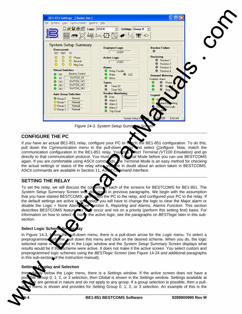
14-4 BE1-851 BESTCOMS Software 9289900990 Rev M
Figure 14-3. System Setup Summary Screen
CONFIGURE THE PC If you have an actual BE1-851 relay, configure your PC to match the BE1-851 configuration. To do this, pull down the Communication menu in the pull-down menu and select Configure. Now, match the communication configuration in the BE1-851 relay. You may select Terminal (VT100 Emulation) and go directly to that communication protocol. You must close Terminal Mode before you can use BESTCOMS again. If you are comfortable using ASCII commands, the Terminal Mode is an easy method for checking the actual settings or status of the relay when you are in doubt about an action taken in BESTCOMS. ASCII commands are available in Section 11, ASCII Command Interface.
SETTING THE RELAY To set the relay, we will discuss the contents of each of the screens for BESTCOMS for BE1-851. The System Setup Summary Screen was discussed in previous paragraphs. We begin with the assumption that you have started BESTCOMS, connected the PC to the relay, and configured your PC to the relay. If the default settings are active in your relay, you will have to change the logic to clear the Major alarm or disable the Logic = None Alarm. See Section 6, Reporting and Alarms, Alarms Function. This section describes BESTCOMS features as they occur and not on a priority (perform this setting first) basis. For information on how to select or name the active logic, see the paragraphs on BESTlogic later in this sub-section.
Select Logic Scheme for Display In Figure 14-3, below the pull-down menu, there is a pull-down arrow for the Logic menu. To select a preprogrammed scheme, pull down this menu and click on the desired scheme. When you do, the logic selected name is displayed in the Logic window and the System Setup Summary Screen displays what results would be if that scheme were active. It does not make it the active screen. You select custom and preprogrammed logic schemes using the BESTlogic Screen (see Figure 14-24 and additional paragraphs in this sub-section of the instruction manual).
Settings Display and Selection Immediately below the Logic menu, there is a Settings window. If the active screen does not have a possible Group 0, 1, 2, or 3 selection, then Global is shown in the Settings window. Settings available at this time are general in nature and do not apply to any group. If a group selection is possible, then a pull-down menu is shown and provides for Setting Group 0, 1, 2, or 3 selection. An example of this is the
www . El
ectric
alPar
tMan
uals
. com
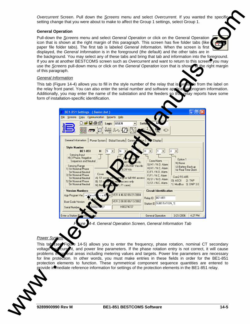
9289900990 Rev M BE1-851 BESTCOMS Software 14-5
Overcurrent Screen. Pull down the Screens menu and select Overcurrent. If you wanted the specific setting change that you were about to make to affect the Group 1 settings, select Group 1.
General Operation Pull-down the Screens menu and select General Operation or click on the General Operation icon that is shown at the right margin of this paragraph. This screen has five folder tabs (like paper file folder tabs). The first tab is labeled General Information. When the screen is first displayed, the General Information is in the foreground (the default) and the other tabs are in the background. You may select any of these tabs and bring that tab and information into the foreground. If you are at another BESTCOMS screen such as Overcurrent and want to return to this screen, you may use the Screens pull-down menu or click on the General Operation icon that is shown at the right margin of this paragraph.
General Information This tab (Figure 14-4) allows you to fill in the style number of the relay that is available from the label on the relay front panel. You can also enter the serial number and software application program information. Additionally, you may enter the name of the substation and the feeders so that relay reports have some form of installation-specific identification.
Figure 14-4. General Operation Screen, General Information Tab
Power System This tab (see Figure 14-5) allows you to enter the frequency, phase rotation, nominal CT secondary voltage and current, and power line parameters. If the phase rotation entry is not correct, it will cause problems in several areas including metering values and targets. Power line parameters are necessary for line protection. In other words, you must make entries in these fields in order for the BE1-851 protection elements to function. These symmetrical component sequence quantities are entered to provide immediate reference information for settings of the protection elements in the BE1-851 relay.
www . El
ectric
alPar
tMan
uals
. com

14-6 BE1-851 BESTCOMS Software 9289900990 Rev M
Figure 14-5. General Operation Screen, Power System Tab
Global Security Each of three communication ports and the four functional areas (Global, Settings, Reports, and Control) has password security. See Figure 14-6. This allows the user to customize password protection for all ports. For example, you could allow technicians to have global access to all three functional areas via the front communication port. You could also restrict the rear port that is connected to a modem to read-only access. If you select Show Passwords and notice that the default passwords have not been changed, then you may change all four passwords appear and can be changed. If the global password has been changed, a dialog box appears explaining that you must enter the global password to enable viewing and editing the existing passwords. After entering the global password, the passwords and enable boxes appear. You may then make changes in all areas. Clicking a box for a specific communication port toggles the functional area for that port either ON or OFF. Notice that the front panel human-machine interface (HMI) and communications port zero are combined and considered as one.
www . El
ectric
alPar
tMan
uals
. com
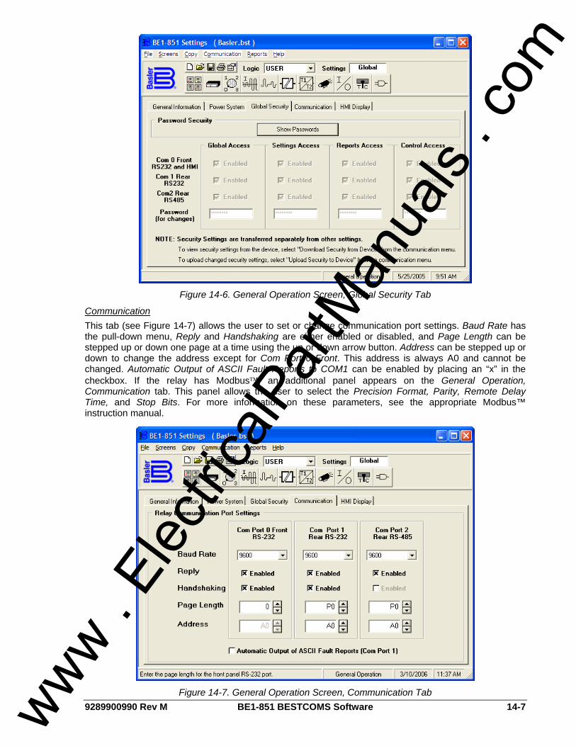
9289900990 Rev M BE1-851 BESTCOMS Software 14-7
Figure 14-6. General Operation Screen, Global Security Tab
Communication This tab (see Figure 14-7) allows the user to set or change communication port settings. Baud Rate has the pull-down menu, Reply and Handshaking are either enabled or disabled, and Page Length can be stepped up or down one page at a time using the up or down arrow button. Address can be stepped up or down to change the address except for Com Port 0 Front. This address is always A0 and cannot be changed. Automatic Output of ASCII Fault Reports to COM1 can be enabled by placing an “x” in the checkbox. If the relay has Modbus™, an additional panel appears on the General Operation, Communication tab. This panel allows the user to select the Precision Format, Parity, Remote Delay Time, and Stop Bits. For more information on these parameters, see the appropriate Modbus™ instruction manual.
Figure 14-7. General Operation Screen, Communication Tab
www . El
ectric
alPar
tMan
uals
. com
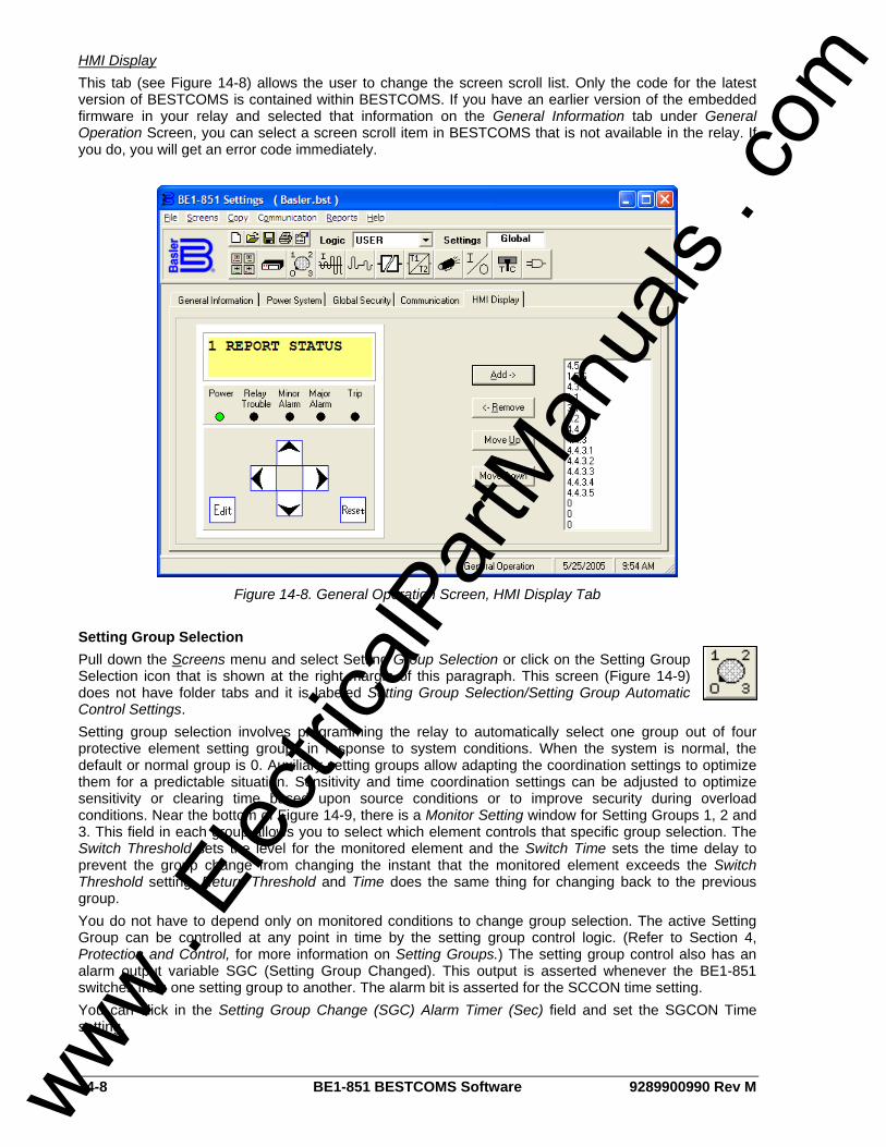
14-8 BE1-851 BESTCOMS Software 9289900990 Rev M
HMI Display This tab (see Figure 14-8) allows the user to change the screen scroll list. Only the code for the latest version of BESTCOMS is contained within BESTCOMS. If you have an earlier version of the embedded firmware in your relay and selected that information on the General Information tab under General Operation Screen, you can select a screen scroll item in BESTCOMS that is not available in the relay. If you do, you will get an error code immediately.
Figure 14-8. General Operation Screen, HMI Display Tab
Setting Group Selection Pull down the Screens menu and select Setting Group Selection or click on the Setting Group Selection icon that is shown at the right margin of this paragraph. This screen (Figure 14-9) does not have folder tabs and it is labeled Setting Group Selection/Setting Group Automatic Control Settings. Setting group selection involves programming the relay to automatically select one group out of four protective element setting groups in response to system conditions. When the system is normal, the default or normal group is 0. Auxiliary setting groups allow adapting the coordination settings to optimize them for a predictable situation. Sensitivity and time coordination settings can be adjusted to optimize sensitivity or clearing time based upon source conditions or to improve security during overload conditions. Near the bottom of Figure 14-9, there is a Monitor Setting window for Setting Groups 1, 2 and 3. This field in each group allows you to select which element controls that specific group selection. The Switch Threshold sets the level for the monitored element and the Switch Time sets the time delay to prevent the group change from changing the instant that the monitored element exceeds the Switch Threshold setting. Return Threshold and Time does the same thing for changing back to the previous group. You do not have to depend only on monitored conditions to change group selection. The active Setting Group can be controlled at any point in time by the setting group control logic. (Refer to Section 4, Protection and Control, for more information on Setting Groups.) The setting group control also has an alarm output variable SGC (Setting Group Changed). This output is asserted whenever the BE1-851 switches from one setting group to another. The alarm bit is asserted for the SCCON time setting. You can click in the Setting Group Change (SGC) Alarm Timer (Sec) field and set the SGCON Time setting.
www . El
ectric
alPar
tMan
uals
. com
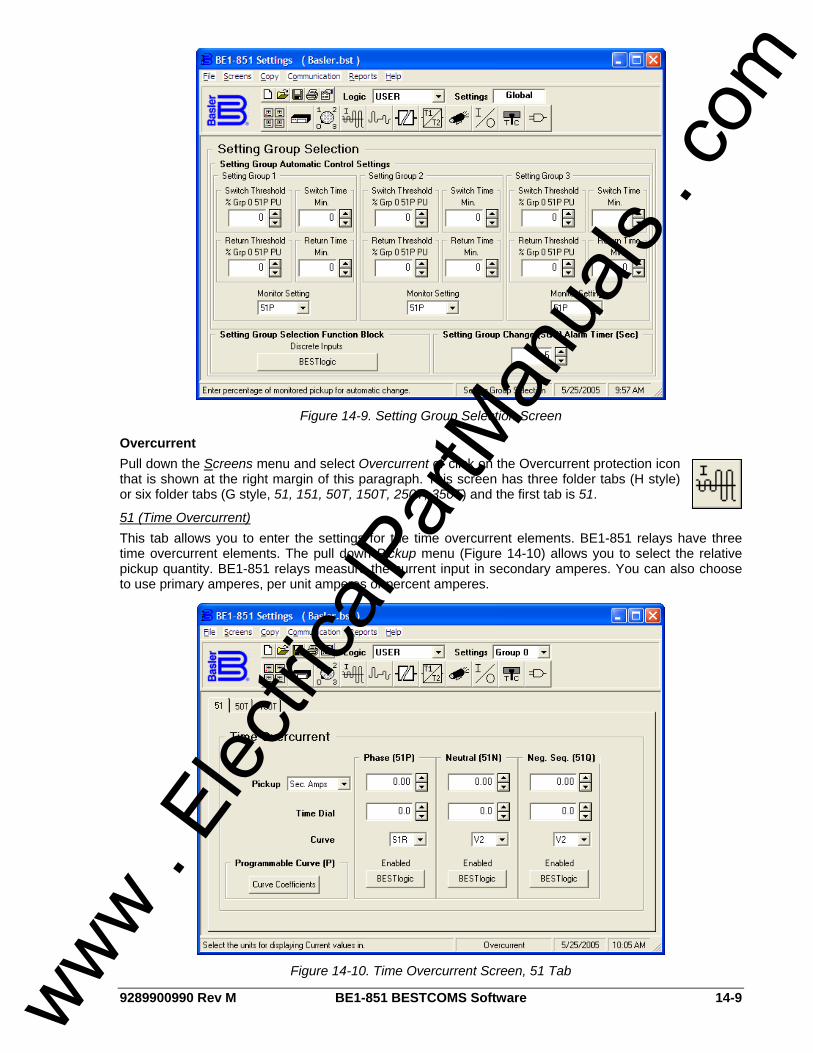
9289900990 Rev M BE1-851 BESTCOMS Software 14-9
Figure 14-9. Setting Group Selection Screen
Overcurrent Pull down the Screens menu and select Overcurrent or click on the Overcurrent protection icon that is shown at the right margin of this paragraph. This screen has three folder tabs (H style) or six folder tabs (G style, 51, 151, 50T, 150T, 250T, 350T) and the first tab is 51.
51 (Time Overcurrent) This tab allows you to enter the settings for the time overcurrent elements. BE1-851 relays have three time overcurrent elements. The pull down Pickup menu (Figure 14-10) allows you to select the relative pickup quantity. BE1-851 relays measure the current input in secondary amperes. You can also choose to use primary amperes, per unit amperes or percent amperes.
Figure 14-10. Time Overcurrent Screen, 51 Tab
www . El
ectric
alPar
tMan
uals
. com
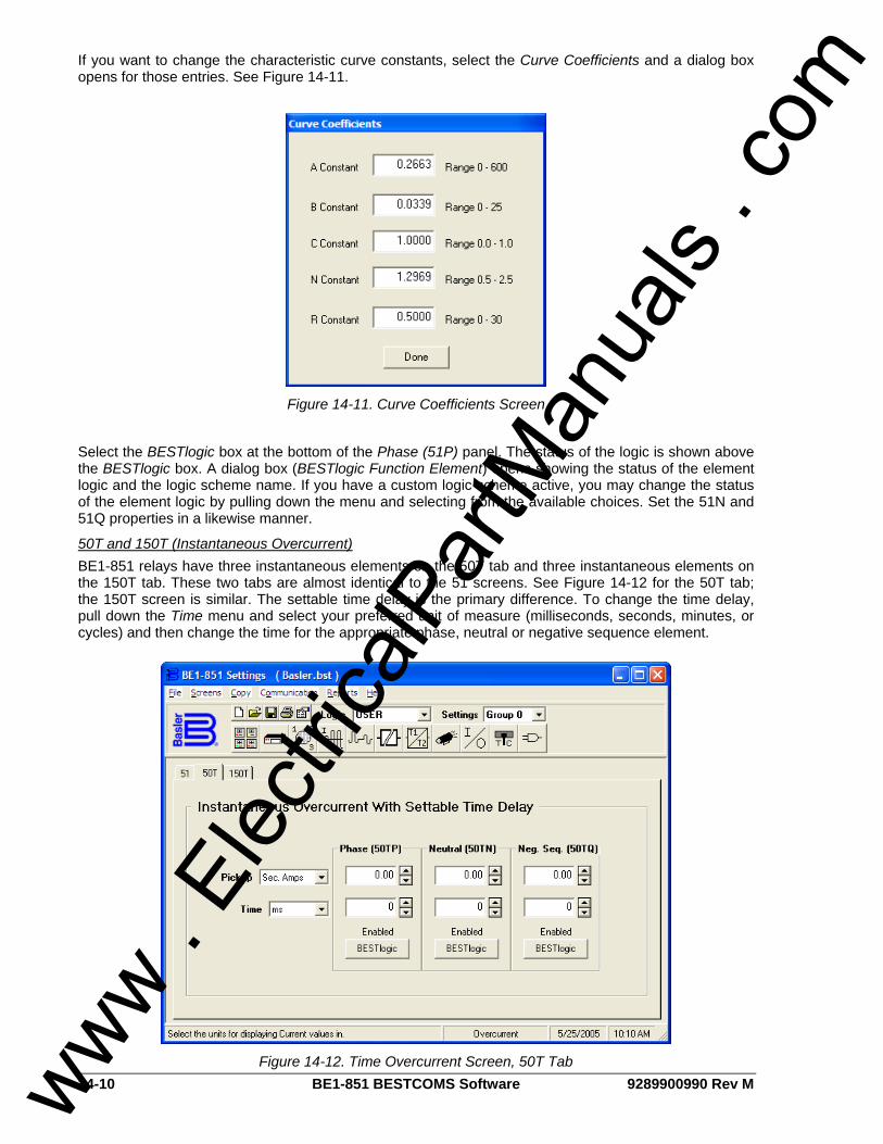
14-10 BE1-851 BESTCOMS Software 9289900990 Rev M
If you want to change the characteristic curve constants, select the Curve Coefficients and a dialog box opens for those entries. See Figure 14-11.
Figure 14-11. Curve Coefficients Screen
Select the BESTlogic box at the bottom of the Phase (51P) panel. The status of the logic is shown above the BESTlogic box. A dialog box (BESTlogic Function Element) opens showing the status of the element logic and the logic scheme name. If you have a custom logic scheme active, you may change the status of the element logic by pulling down the menu and selecting from the available choices. Set the 51N and 51Q properties in a likewise manner.
50T and 150T (Instantaneous Overcurrent) BE1-851 relays have three instantaneous elements on the 50T tab and three instantaneous elements on the 150T tab. These two tabs are almost identical to the 51 screens. See Figure 14-12 for the 50T tab; the 150T screen is similar. The settable time delay is the primary difference. To change the time delay, pull down the Time menu and select your preferred unit of measure (milliseconds, seconds, minutes, or cycles) and then change the time for the appropriate phase, neutral or negative sequence element.
Figure 14-12. Time Overcurrent Screen, 50T Tab
www . El
ectric
alPar
tMan
uals
. com
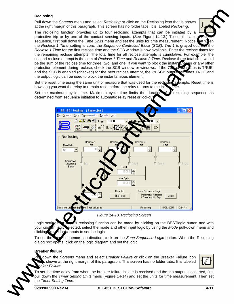
9289900990 Rev M BE1-851 BESTCOMS Software 14-11
Reclosing Pull down the Screens menu and select Reclosing or click on the Reclosing icon that is shown at the right margin of this paragraph. This screen has no folder tabs. It is labeled Reclosing. The reclosing function provides up to four reclosing attempts that can be initiated by a protective trip or by one of the contact sensing inputs. (See Figure 14-13.) To set the actual reclose sequence, first pull down the Time Units menu and set the units for time measurement. Notice that when the Reclose 1 Time setting is zero, the Sequence Controlled Block (SCB), Trip 1 is grayed out. Set the Reclose 1 Time for the first reclose time and the SCB window is now available. Enter the reclose times for the remaining reclose attempts. The total time for all reclose attempts is cumulative. For example, the second reclose attempt is the sum of Reclose 1 Time and Reclose 2 Time. Reclose three total time would be the sum of the reclose time for three, two, and one. If you want to block the instantaneous or any other protection element during reclose, check the SCB window or windows. If the 79C or 52 status is TRUE, and the SCB is enabled (checked) for the next reclose attempt, the 79 SCB output becomes TRUE and the output logic can be used to block the instantaneous element. Set the reset time using the same unit of measure that was used for the reclosing attempts. Reset time is how long you want the relay to remain reset before the relay returns to the initial state. Set the maximum cycle time. Maximum cycle time limits the duration of a reclosing sequence as determined from sequence initiation to automatic relay reset or lockout.
Figure 14-13. Reclosing Screen
Logic settings for the 79 reclosing function can be made by clicking on the BESTlogic button and with your custom logic selected, select the mode and other input logic by using the Mode pull-down menu and clicking on the logic inputs to set the logic. To set the zone sequence coordination, click on the Zone-Sequence Logic button. When the Reclosing dialog box opens, click on the logic diagram and set the logic.
Breaker Failure Pull down the Screens menu and select Breaker Failure or click on the Breaker Failure icon that is shown at the right margin of this paragraph. This screen has no folder tabs. It is labeled Breaker Failure. To set the time delay from when the breaker failure initiate is received and the trip output is asserted, first pull down the Timer Setting Units menu (Figure 14-14) and set the units for time measurement. Then set the Timer Setting Time.
www . El
ectric
alPar
tMan
uals
. com
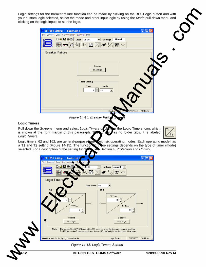
14-12 BE1-851 BESTCOMS Software 9289900990 Rev M
Logic settings for the breaker failure function can be made by clicking on the BESTlogic button and with your custom logic selected, select the mode and other input logic by using the Mode pull-down menu and clicking on the logic inputs to set the logic.
Figure 14-14. Breaker Failure Screen
Logic Timers Pull down the Screens menu and select Logic Timers or click on the Logic Timers icon, which is shown at the right margin of this paragraph. This screen has no folder tabs. It is labeled Logic Timers. Logic timers, 62 and 162, are general-purpose timers with six operating modes. Each operating mode has a T1 and T2 setting (Figure 14-15). The function of these settings depends on the type of timer (mode) selected. For a description of the setting functions, see Section 4, Protection and Control.
Figure 14-15. Logic Timers Screen
www . El
ectric
alPar
tMan
uals
. com
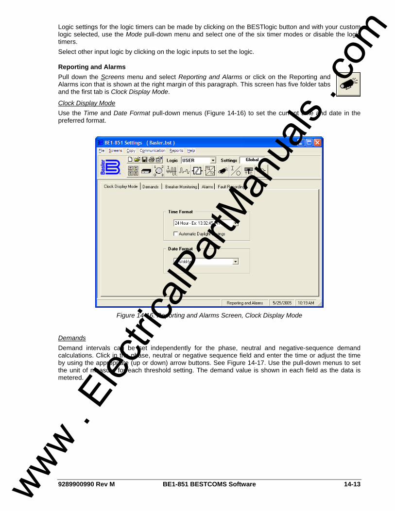
9289900990 Rev M BE1-851 BESTCOMS Software 14-13
Logic settings for the logic timers can be made by clicking on the BESTlogic button and with your custom logic selected, use the Mode pull-down menu and select one of the six timer modes or disable the logic timers. Select other input logic by clicking on the logic inputs to set the logic.
Reporting and Alarms Pull down the Screens menu and select Reporting and Alarms or click on the Reporting and Alarms icon that is shown at the right margin of this paragraph. This screen has five folder tabs and the first tab is Clock Display Mode.
Clock Display Mode Use the Time and Date Format pull-down menus (Figure 14-16) to set the current time and date in the preferred format.
Figure 14-16. Reporting and Alarms Screen, Clock Display Mode
Demands Demand intervals can be set independently for the phase, neutral and negative-sequence demand calculations. Click in the phase, neutral or negative sequence field and enter the time or adjust the time by using the appropriate (up or down) arrow buttons. See Figure 14-17. Use the pull-down menus to set the unit of measure for each threshold setting. The demand value is shown in each field as the data is metered.
www . El
ectric
alPar
tMan
uals
. com
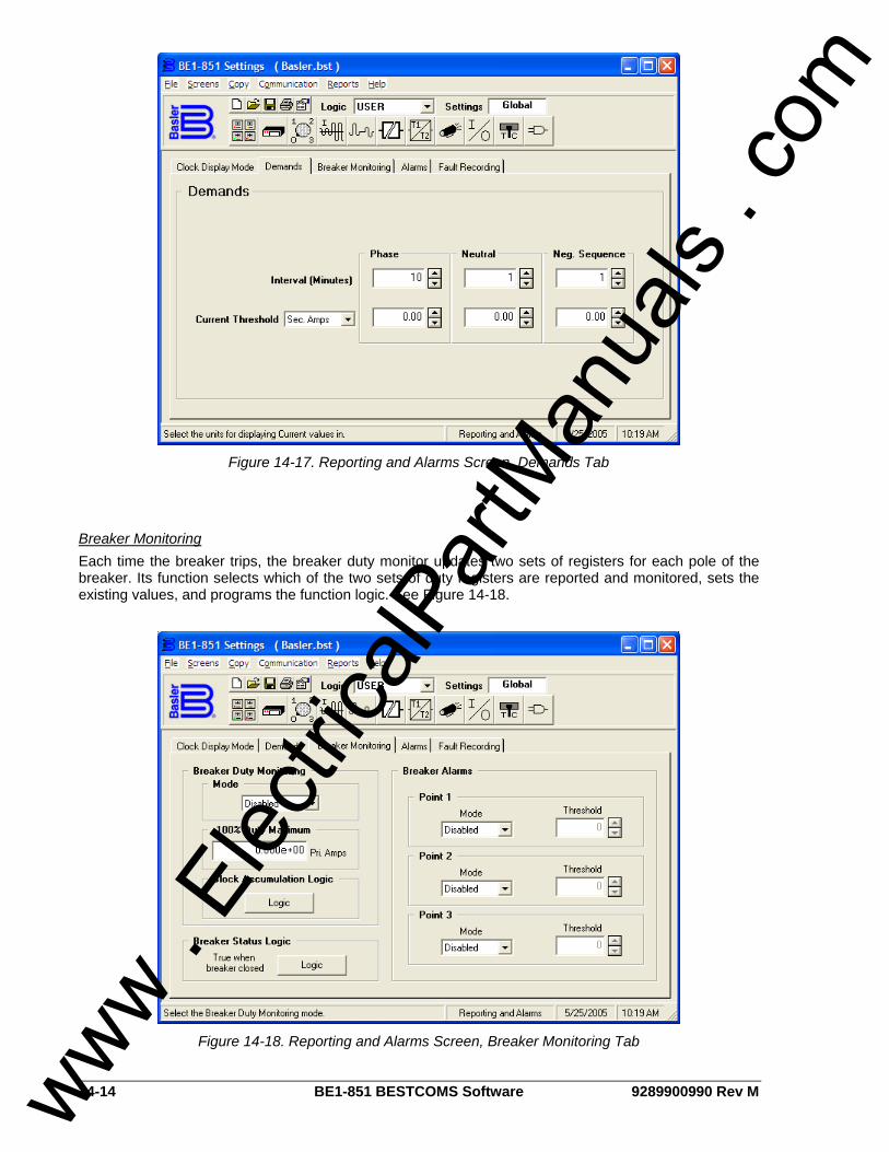
14-14 BE1-851 BESTCOMS Software 9289900990 Rev M
Figure 14-17. Reporting and Alarms Screen, Demands Tab
Breaker Monitoring Each time the breaker trips, the breaker duty monitor updates two sets of registers for each pole of the breaker. Its function selects which of the two sets of duty registers are reported and monitored, sets the existing values, and programs the function logic. See Figure 14-18.
Figure 14-18. Reporting and Alarms Screen, Breaker Monitoring Tab
www . El
ectric
alPar
tMan
uals
. com
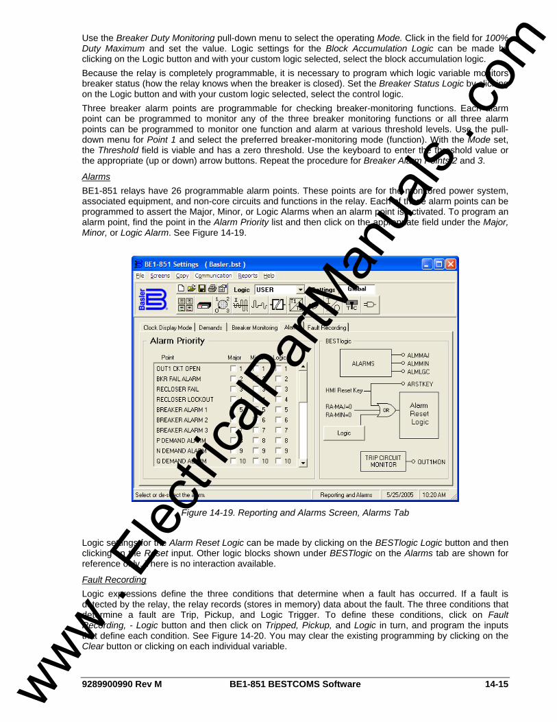
9289900990 Rev M BE1-851 BESTCOMS Software 14-15
Use the Breaker Duty Monitoring pull-down menu to select the operating Mode. Click in the field for 100% Duty Maximum and set the value. Logic settings for the Block Accumulation Logic can be made by clicking on the Logic button and with your custom logic selected, select the block accumulation logic. Because the relay is completely programmable, it is necessary to program which logic variable monitors breaker status (how the relay knows when the breaker is closed). Set the Breaker Status Logic by clicking on the Logic button and with your custom logic selected, select the control logic. Three breaker alarm points are programmable for checking breaker-monitoring functions. Each alarm point can be programmed to monitor any of the three breaker monitoring functions or all three alarm points can be programmed to monitor one function and alarm at various threshold levels. Use the pull-down menu for Point 1 and select the preferred breaker-monitoring mode (function). With the Mode set, the Threshold field is viable and has a zero threshold. Use the keyboard to enter the threshold value or the appropriate (up or down) arrow buttons. Repeat the procedure for Breaker Alarm Points 2 and 3.
Alarms BE1-851 relays have 26 programmable alarm points. These points are for the monitored power system, associated equipment, and non-core circuits and functions in the relay. Each of these alarm points can be programmed to assert the Major, Minor, or Logic Alarms when an alarm point is activated. To program an alarm point, find the point in the Alarm Priority list and then click on the appropriate field under the Major, Minor, or Logic Alarm. See Figure 14-19.
Figure 14-19. Reporting and Alarms Screen, Alarms Tab
Logic settings for the Alarm Reset Logic can be made by clicking on the BESTlogic Logic button and then clicking on the Reset input. Other logic blocks shown under BESTlogic on the Alarms tab are shown for reference only. There is no interaction available.
Fault Recording Logic expressions define the three conditions that determine when a fault has occurred. If a fault is detected by the relay, the relay records (stores in memory) data about the fault. The three conditions that determine a fault are Trip, Pickup, and Logic Trigger. To define these conditions, click on Fault Recording, - Logic button and then click on Tripped, Pickup, and Logic in turn, and program the inputs that define each condition. See Figure 14-20. You may clear the existing programming by clicking on the Clear button or clicking on each individual variable.
www . El
ectric
alPar
tMan
uals
. com
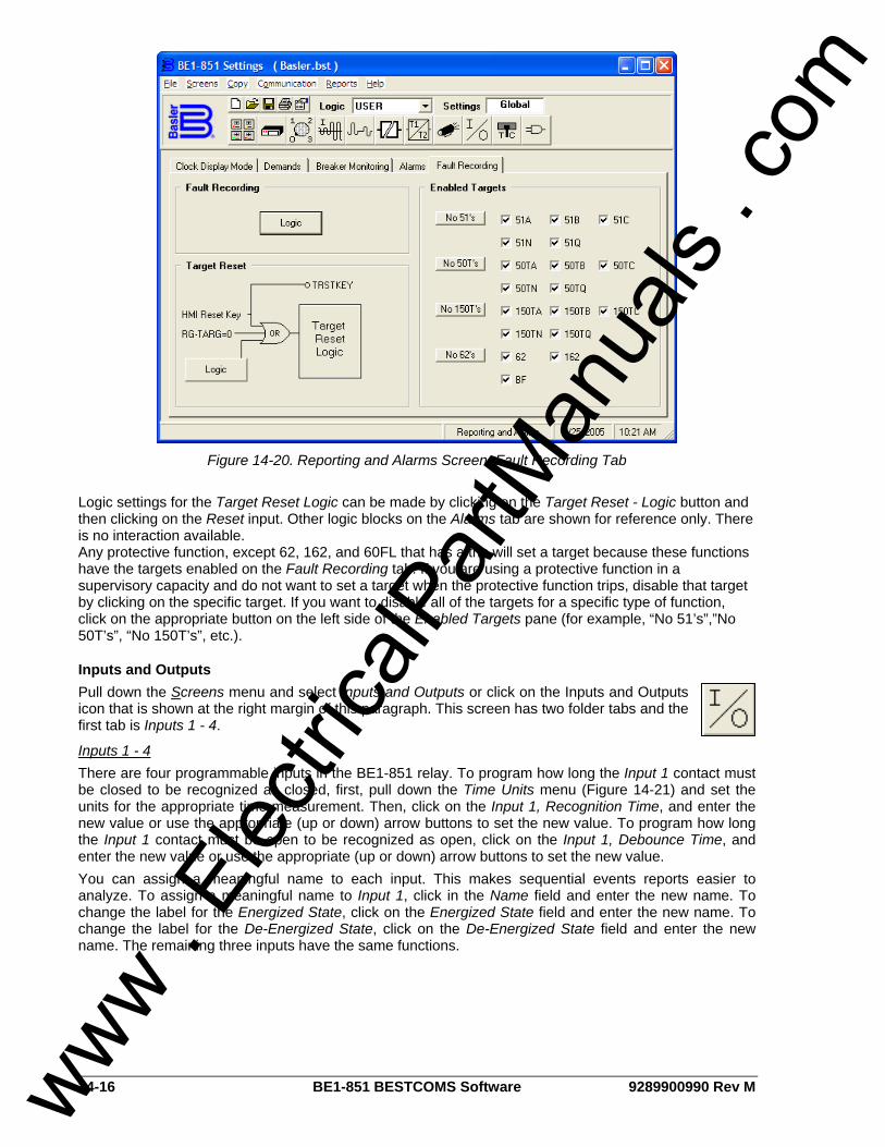
14-16 BE1-851 BESTCOMS Software 9289900990 Rev M
Figure 14-20. Reporting and Alarms Screen, Fault Recording Tab
Logic settings for the Target Reset Logic can be made by clicking on the Target Reset - Logic button and then clicking on the Reset input. Other logic blocks on the Alarms tab are shown for reference only. There is no interaction available. Any protective function, except 62, 162, and 60FL that has a trip will set a target because these functions have the targets enabled on the Fault Recording tab. If you are using a protective function in a supervisory capacity and do not want to set a target when the protective function trips, disable that target by clicking on the specific target. If you want to disable all of the targets for a specific type of function, click on the appropriate button on the left side of the Enabled Targets pane (for example, “No 51’s”,”No 50T’s”, “No 150T’s”, etc.).
Inputs and Outputs Pull down the Screens menu and select Inputs and Outputs or click on the Inputs and Outputs icon that is shown at the right margin of this paragraph. This screen has two folder tabs and the first tab is Inputs 1 - 4.
Inputs 1 - 4 There are four programmable inputs in the BE1-851 relay. To program how long the Input 1 contact must be closed to be recognized as closed, first, pull down the Time Units menu (Figure 14-21) and set the units for the appropriate time measurement. Then, click on the Input 1, Recognition Time, and enter the new value or use the appropriate (up or down) arrow buttons to set the new value. To program how long the Input 1 contact must be open to be recognized as open, click on the Input 1, Debounce Time, and enter the new value or use the appropriate (up or down) arrow buttons to set the new value. You can assign a meaningful name to each input. This makes sequential events reports easier to analyze. To assign a meaningful name to Input 1, click in the Name field and enter the new name. To change the label for the Energized State, click on the Energized State field and enter the new name. To change the label for the De-Energized State, click on the De-Energized State field and enter the new name. The remaining three inputs have the same functions.
www . El
ectric
alPar
tMan
uals
. com
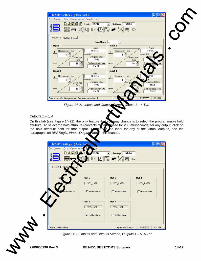
9289900990 Rev M BE1-851 BESTCOMS Software 14-17
Figure 14-21. Inputs and Outputs Screen, Inputs 1 – 4 Tab
Outputs 1 – 5, A On this tab (see Figure 14-22), the only feature that you may change is to select the programmable hold attribute. To select the hold attribute (contacts remain closed for 200 milliseconds) for any output, click on the hold attribute field for that output. To change the label for any of the virtual outputs, see the paragraphs on BESTlogic, Virtual Outputs later in this manual.
Figure 14-22. Inputs and Outputs Screen, Outputs 1 – 5, A Tab
www . El
ectric
alPar
tMan
uals
. com
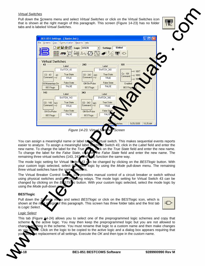
14-18 BE1-851 BESTCOMS Software 9289900990 Rev M
Virtual Switches Pull down the Screens menu and select Virtual Switches or click on the Virtual Switches icon that is shown at the right margin of this paragraph. This screen (Figure 14-23) has no folder tabs and is labeled Virtual Switches.
Figure 14-23. Virtual Switches Screen
You can assign a meaningful name or label to each virtual switch. This makes sequential events reports easier to analyze. To assign a meaningful label to Virtual Switch 43, click in the Label field and enter the new name. To change the label for the True State, click on the True State field and enter the new name. To change the label for the False State, click on the False State field and enter the new name. The remaining three virtual switches (143, 243, and 343) function the same way. The mode logic setting for Virtual Switch 43 can be changed by clicking on the BESTlogic button. With your custom logic selected, select the mode logic by using the Mode pull-down menu. The remaining three virtual switches have the same functions. The Virtual Breaker Control Switch 101 provides manual control of a circuit breaker or switch without using physical switches and/or interposing relays. The mode logic setting for Virtual Switch 43 can be changed by clicking on the BESTlogic button. With your custom logic selected, select the mode logic by using the Mode pull-down menu.
BESTlogic Pull down the Screens menu and select BESTlogic or click on the BESTlogic icon, which is shown at the right margin of this paragraph. This screen has three folder tabs and the first tab is Logic Select.
Logic Select This tab (Figure 14-24) allows you to select one of the preprogrammed logic schemes and copy that scheme to the active logic. You may then keep the preprogrammed logic but you are not allowed to change anything in the scheme. You must rename that logic to a custom name and then make changes as you desire. Click on the logic to be copied to the active logic and a dialog box appears requiring that you okay the replacement of all settings. Execute the OK and then type in the custom name.
www . El
ectric
alPar
tMan
uals
. com
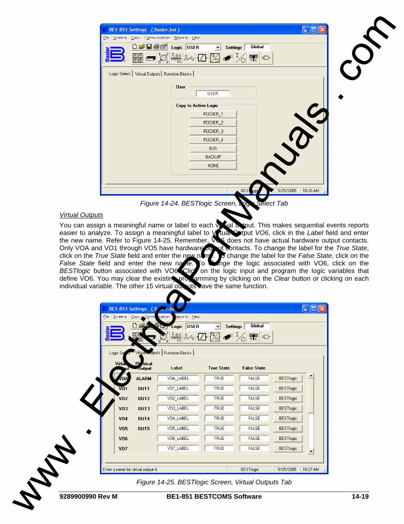
9289900990 Rev M BE1-851 BESTCOMS Software 14-19
Figure 14-24. BESTlogic Screen, Logic Select Tab
Virtual Outputs You can assign a meaningful name or label to each virtual output. This makes sequential events reports easier to analyze. To assign a meaningful label to Virtual Output VO6, click in the Label field and enter the new name. Refer to Figure 14-25. Remember, VO6 does not have actual hardware output contacts. Only VOA and VO1 through VO5 have hardware output contacts. To change the label for the True State, click on the True State field and enter the new name. To change the label for the False State, click on the False State field and enter the new name. To change the logic associated with VO6, click on the BESTlogic button associated with VO6. Click on the logic input and program the logic variables that define VO6. You may clear the existing programming by clicking on the Clear button or clicking on each individual variable. The other 15 virtual outputs have the same function.
Figure 14-25. BESTlogic Screen, Virtual Outputs Tab
www . El
ectric
alPar
tMan
uals
. com
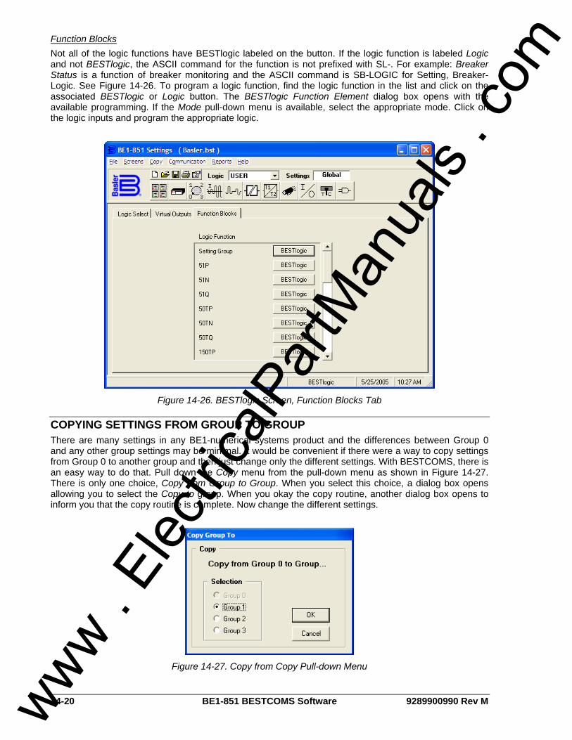
14-20 BE1-851 BESTCOMS Software 9289900990 Rev M
Function Blocks Not all of the logic functions have BESTlogic labeled on the button. If the logic function is labeled Logic and not BESTlogic, the ASCII command for the function is not prefixed with SL-. For example: Breaker Status is a function of breaker monitoring and the ASCII command is SB-LOGIC for Setting, Breaker-Logic. See Figure 14-26. To program a logic function, find the logic function in the list and click on the associated BESTlogic or Logic button. The BESTlogic Function Element dialog box opens with the available programming. If the Mode pull-down menu is available, select the appropriate mode. Click on the logic inputs and program the appropriate logic.
Figure 14-26. BESTlogic Screen, Function Blocks Tab
COPYING SETTINGS FROM GROUP TO GROUP There are many settings in any BE1-numerical systems product and the differences between Group 0 and any other group settings may be minimal. It would be convenient if there were a way to copy settings from Group 0 to another group and then just change only the different settings. With BESTCOMS, there is an easy way to do that. Pull down the Copy menu from the pull-down menu as shown in Figure 14-27. There is only one choice, Copy from Group to Group. When you select this choice, a dialog box opens allowing you to select the Copy to group. When you okay the copy routine, another dialog box opens to inform you that the copy routine is complete. Now change the different settings.
Figure 14-27. Copy from Copy Pull-down Menu
www . El
ectric
alPar
tMan
uals
. com
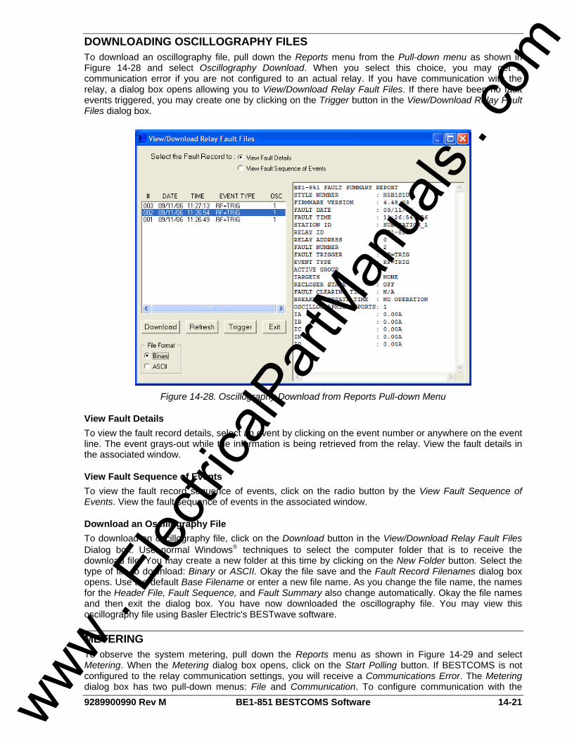
9289900990 Rev M BE1-851 BESTCOMS Software 14-21
DOWNLOADING OSCILLOGRAPHY FILES To download an oscillography file, pull down the Reports menu from the Pull-down menu as shown in Figure 14-28 and select Oscillography Download. When you select this choice, you may get a communication error if you are not configured to an actual relay. If you have communication with the relay, a dialog box opens allowing you to View/Download Relay Fault Files. If there have been no fault events triggered, you may create one by clicking on the Trigger button in the View/Download Relay Fault Files dialog box.
Figure 14-28. Oscillography Download from Reports Pull-down Menu
View Fault Details To view the fault record details, select an event by clicking on the event number or anywhere on the event line. The event grays-out while the information is being retrieved from the relay. View the fault details in the associated window.
View Fault Sequence of Events To view the fault record sequence of events, click on the radio button by the View Fault Sequence of Events. View the fault sequence of events in the associated window.
Download an Oscillography File To download an oscillography file, click on the Download button in the View/Download Relay Fault Files Dialog box. Use normal Windows® techniques to select the computer folder that is to receive the download file. You may create a new folder at this time by clicking on the New Folder button. Select the type of file to download: Binary or ASCII. Okay the file save and the Fault Record Filenames dialog box opens. Use the default Base Filename or enter a new file name. As you change the file name, the names for the Header File, Fault Sequence, and Fault Summary also change automatically. Okay the file names and then exit the dialog box. You have now downloaded the oscillography file. You may view this oscillography file using Basler Electric's BESTwave software.
METERING To observe the system metering, pull down the Reports menu as shown in Figure 14-29 and select Metering. When the Metering dialog box opens, click on the Start Polling button. If BESTCOMS is not configured to the relay communication settings, you will receive a Communications Error. The Metering dialog box has two pull-down menus: File and Communication. To configure communication with the
www . El
ectric
alPar
tMan
uals
. com
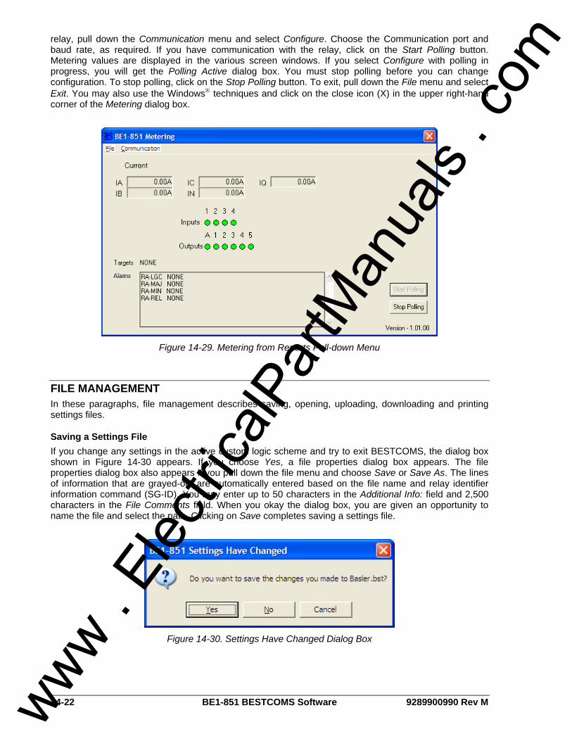
14-22 BE1-851 BESTCOMS Software 9289900990 Rev M
relay, pull down the Communication menu and select Configure. Choose the Communication port and baud rate, as required. If you have communication with the relay, click on the Start Polling button. Metering values are displayed in the various screen windows. If you select Configure with polling in progress, you will get the Polling Active dialog box. You must stop polling before you can change configuration. To stop polling, click on the Stop Polling button. To exit, pull down the File menu and select Exit. You may also use the Windows® techniques and click on the close icon (X) in the upper right-hand corner of the Metering dialog box.
Figure 14-29. Metering from Reports Pull-down Menu
FILE MANAGEMENT In these paragraphs, file management describes saving, opening, uploading, downloading and printing settings files.
Saving a Settings File If you change any settings in the active custom logic scheme and try to exit BESTCOMS, the dialog box shown in Figure 14-30 appears. If you choose Yes, a file properties dialog box appears. The file properties dialog box also appears if you pull down the file menu and choose Save or Save As. The lines of information that are grayed-out are automatically entered based on the file name and relay identifier information command (SG-ID). You may enter up to 50 characters in the Additional Info: field and 2,500 characters in the File Comments field. When you okay the dialog box, you are given an opportunity to name the file and select the path. Clicking on Save completes saving a settings file.
Figure 14-30. Settings Have Changed Dialog Box
www . El
ectric
alPar
tMan
uals
. com

9289900990 Rev M BE1-851 BESTCOMS Software 14-23
Opening a Settings File To open a settings file into BESTCOMS, pull down the File menu and choose Open. If the settings in your BESTCOMS have changed, a dialog box will open asking you if want to save the current settings changes. You may choose Yes or No. After you have taken the required action to save or not save the current settings, the Open dialog box appears. This dialog box allows you to use normal Windows® techniques to select the file that you want to open. Select the file and open it and the file settings have been brought into BESTCOMS.
Uploading a Settings File To upload a settings file to the BE1-851 relay, you must first open the file through BESTCOMS or create the file using BESTCOMS. Then pull down the Communication menu and select Upload Settings to Device. You are prompted to enter the password. If the password is correct, the upload begins and the percent complete loading bar is shown. At upload completion, you are asked if you want to save the settings and make them active. After replying, you are informed of the status: Yes – settings are saved or No – settings are discarded. If you would like to view the file names as they are uploaded, pull down the Communication menu and select Configure. When the Configure Communication Port dialog box opens, click the On button for Show Commands During Data Transfer and then OK. Now, during data transfer, you will see two screens (Sending and Status) and the percent complete loading bar. If a data transfer error occurs, you can briefly see the error notification in the Status window. The file settings will not be uploaded and the changes discarded. You may then scroll through the Status window until you find the error notification. Click on the error notification and the data file that transferred in error is shown in the Sending window.
Downloading a Settings File To download a settings file from a BE1-851 relay, you must pull down the Communication menu and select Download Settings from Device. If the settings in your BESTCOMS have changed, a dialog box will open asking if you want to save the current settings changes. You may choose Yes or No. After you have taken the required action to save or not save the current settings, the downloading is executed.
Printing a Settings File To print a settings file, pull down the File menu and select Print. A dialog box, Print BE1-851 Settings File, opens with the settings file shown and typical Windows® choices to setup the page and the printer. Execute these commands as necessary and then select Print. You may also export the settings file to a text file. Pull down the File menu and select Export to Text. A dialog box, Export to Text File opens with the settings file shown. Execute the OK command and then use normal Windows® techniques to select the path. Execute the SAVE command and you now have a text file of your BESTCOMS settings.
SETTINGS COMPARE BESTCOMS has the ability to compare two different settings files. To use this feature, pull down the Reports menu and select Settings Compare. The BESTCOMS Settings Compare Setup dialog box appears (Figure 14-31). Select the location of the first file to compare under Left Settings Source and select the location of the second file to compare under Right Settings Source. If you are comparing a settings file located on your PC hard drive or portable media, click the folder button and navigate to the file. If you want to compare settings downloaded from a unit, click the RS-232 button to set up the communication port and baud rate. Click the Compare button to compare the selected settings files.
www . El
ectric
alPar
tMan
uals
. com
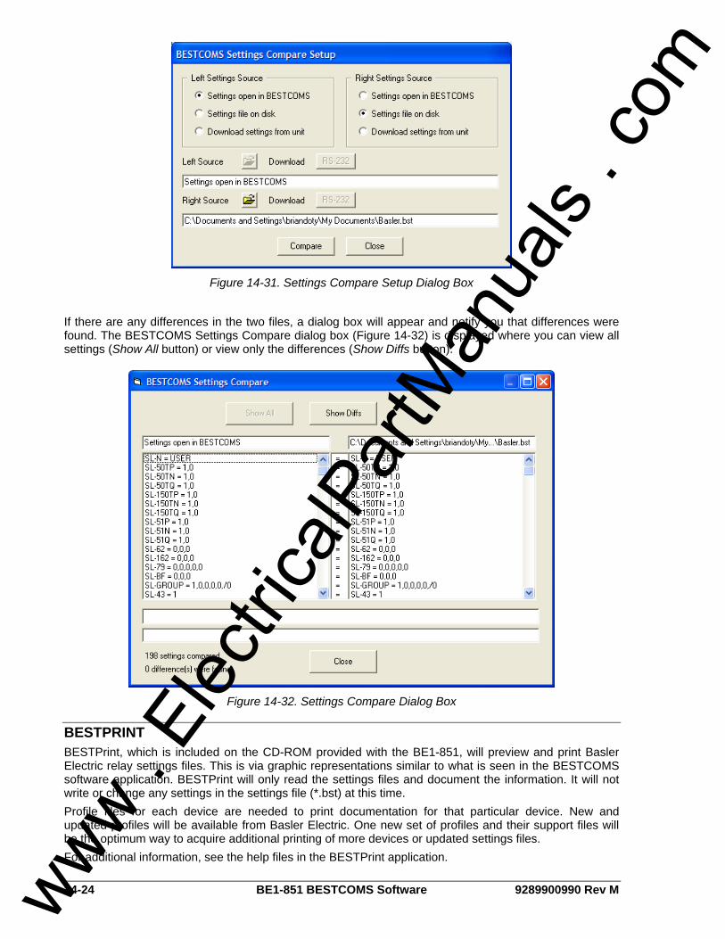
14-24 BE1-851 BESTCOMS Software 9289900990 Rev M
Figure 14-31. Settings Compare Setup Dialog Box
If there are any differences in the two files, a dialog box will appear and notify you that differences were found. The BESTCOMS Settings Compare dialog box (Figure 14-32) is displayed where you can view all settings (Show All button) or view only the differences (Show Diffs button).
Figure 14-32. Settings Compare Dialog Box
BESTPRINT BESTPrint, which is included on the CD-ROM provided with the BE1-851, will preview and print Basler Electric relay settings files. This is via graphic representations similar to what is seen in the BESTCOMS software application. BESTPrint will only read the settings files and document the information. It will not write or change any settings in the settings file (*.bst) at this time. Profile files for each device are needed to print documentation for that particular device. New and updated profiles will be available from Basler Electric. One new set of profiles and their support files will be the optimum way to acquire additional printing of more devices or updated settings files. For additional information, see the help files in the BESTPrint application.
www . El
ectric
alPar
tMan
uals
. com
9289900990 Rev M BE1-851 Time Overcurrent Characteristic Curves i
APPENDIX A • TIME OVERCURRENT CHARACTERISTIC CURVES
TABLE OF CONTENTS
APPENDIX A • TIME OVERCURRENT CHARACTERISTIC CURVES ...................................................A-1 GENERAL..............................................................................................................................................A-1 CURVE SPECIFICATIONS ...................................................................................................................A-1 TIME OVERCURRENT CHARACTERISTIC CURVE GRAPHS...........................................................A-2
Figures Figure A-1. Time Characteristic Curve S, S1, Short Inverse (Similar to ABB CO-2) ................................A-5 Figure A-2. Time Characteristic Curve S2, Short Inverse (Similar To GE IAC-55)...................................A-6 Figure A-3. Time Characteristic Curve L, L1, Long Inverse (Similar to ABB CO-5) .................................A-7 Figure A-4. Time Characteristic Curve L2, Long Inverse (Similar To GE IAC-66)....................................A-8 Figure A-5. Time Characteristic Curve D, Definite Time (Similar To ABB CO-6) .....................................A-9 Figure A-6. Time Characteristic Curve M, Moderately Inverse (Similar to ABB CO-7)...........................A-10 Figure A-7. Time Characteristic Curve I, I1, Inverse Time (Similar to ABB CO-8) .................................A-11 Figure A-8. Time Characteristic Curve I2, Inverse Time (Similar to GE IAC-51)....................................A-12 Figure A-9. Time Characteristic Curve V, V1, Very Inverse (Similar to ABB CO-9) ...............................A-13 Figure A-10. Time Characteristic Curve V2, Very Inverse (Similar to GE IAC-53) .................................A-14 Figure A-11. Time Characteristic Curve E, E1, Extremely Inverse (Similar to ABB CO-11)...................A-15 Figure A-12. Time Characteristic Curve E2, Extremely Inverse (Similar to GE IAC-77) ........................A-16 Figure A-13. Time Characteristic Curve A, Standard Inverse.................................................................A-17 Figure A-14. Time Characteristic Curve B, Very Inverse ........................................................................A-18 Figure A-15. Time Characteristic Curve C, Extremely Inverse ...............................................................A-19 Figure A-16. Time Characteristic Curve G, Long Time Inverse ..............................................................A-20
Tables Table A-1. 51P, 51N, and 51Q Time Characteristic Curve Constants......................................................A-2 Table A-2. Characteristic Curve Cross-Reference....................................................................................A-3 Table A-3. Time Dial Setting Cross-Reference .........................................................................................A-4
www . El
ectric
alPar
tMan
uals
. com

ii BE1-851 Time Overcurrent Characteristic Curves 9289900990 Rev M
This page intentionally left blank.
www . El
ectric
alPar
tMan
uals
. com

9289900990 Rev M BE1-851 Time Overcurrent Characteristic Curves A-1
APPENDIX A • TIME OVERCURRENT CHARACTERISTIC CURVES
GENERAL Basler Electric inverse time overcurrent systems (ANSI Device 51) provide time/current characteristic curves that very closely emulate most of the common electro-mechanical, induction disk relays that were manufactured in North America. To further improve proper relay coordination, selection of integrated reset or instantaneous reset characteristics is also provided.
CURVE SPECIFICATIONS Timing Accuracy (All 51 Functions): Within ±5% or ±1½ cycles, whichever is greater,
for Fundamental and RMS sensing, and -1½ to +3 cycles for Average sensing, for time dial settings greater than 0.1 and multiples of 2 to 40 times the pickup setting but not over 150 A for 5 A CT units or 30 A for 1 A CT units.
Sixteen inverse time functions and one fixed time
function and one programmable time function can be selected. Characteristic curves for the inverse and definite time functions are defined by the following equations and comply with IEEE C37.112 - 1996.
KDBCM
DAT NT +⋅+−
⋅= Equation A-1
1M
DRT2R−
⋅= Equation A-2
TT = Time to trip when M ≥ 1 TR = Time to reset if relay is set for integrating
reset when M < 1. Otherwise, reset is 50 milliseconds or less
D = TIME DIAL setting (0.0 to 9.9) M = Multiple of PICKUP setting (0 to 40) A, B, C, N, K = Constants for the particular curve R = Constant defining the reset time. Table A-1 lists time characteristic curve
constants. See Figures A-1 through A-16 for graphs of the characteristics.
www . El
ectric
alPar
tMan
uals
. com

A-2 BE1-851 Time Overcurrent Characteristic Curves 9289900990 Rev M
Table A-1. 51P, 51N, and 51Q Time Characteristic Curve Constants
Trip Characteristic Constants ‡ Reset † Curve Selection
Curve Name A B C N K R
S1 S, S1, Short Inverse 0.2663 0.03393 1.0000 1.2969 0.0280 0.5000 S2 S2, Short Inverse 0.0286 0.02080 1.0000 0.9844 0.0280 0.0940 L1 L, L1, Long Inverse 5.6143 2.18592 1.0000 1.0000 0.0280 15.750 L2 L2, Long Inverse 2.3955 0.00000 1.0000 0.3125 0.0280 7.8001 D D, Definite Time 0.4797 0.21359 1.0000 1.5625 0.0280 0.8750 M M, Moderately Inverse 0.3022 0.12840 1.0000 0.5000 0.0280 1.7500 I1 I, I1, Inverse Time 8.9341 0.17966 1.0000 2.0938 0.0280 9.0000 I2 I2, Inverse Time 0.2747 0.10426 1.0000 0.4375 0.0280 0.8868 V1 V, V1, Very Inverse 5.4678 0.10814 1.0000 2.0469 0.0280 5.5000 V2 V2, Very Inverse 4.4309 0.09910 1.0000 1.9531 0.0280 5.8231 E1 E, E1Extremely Inverse 7.7624 0.02758 1.0000 2.0938 0.0280 7.7500 E2 E2, Extremely Inverse 4.9883 0.01290 1.0000 2.0469 0.0280 4.7742 A A, Standard Inverse 0.01414 0.00000 1.0000 0.0200 0.0280 2.0000
B B, Very Inverse (I2t) 1.4636 0.00000 1.0000 1.0469 0.0280 3.2500
C C, Extremely Inverse (I2t) 8.2506 0.00000 1.0000 2.0469 0.0280 8.0000
G G, Long Time Inverse (I2t) 12.1212 0.00000 1.0000 1.0000 0.0280 29.0000
F Fixed Time ∗ 0.0000 1.00000 0.0000 0.0000 0.0280 1.0000
P Programmable 0 to 600 0 to 25 0 to 1 0.5 to 2.5 0.0280 0 to 30 ∗ Curve F has a fixed delay of one second times the Time Dial setting.
† For integrated reset, append R to the curve name. For example, curve S1 has instantaneous reset. Curve S1R has integrated reset.
‡ The programmable curve allows for four significant digits after the decimal place for every variable.
TIME OVERCURRENT CHARACTERISTIC CURVE GRAPHS Figures A-1 through A-16 illustrate the characteristic curves of the BE1-851 relay. Table A-2 cross-references each curve to existing electromechanical relay characteristics. Equivalent time dial settings were calculated at a value of five times pickup.
www . El
ectric
alPar
tMan
uals
. com

9289900990 Rev M BE1-851 Time Overcurrent Characteristic Curves A-3
Table A-2. Characteristic Curve Cross-Reference
Curve Curve Name Similar To
S1 S, S1, Short Inverse ABB CO-2
S2 S2, Short Inverse GE IAC-55
L1 L, L1, Long Inverse ABB CO-5
L2 L2, Long Inverse GE IAC-66
D D, Definite Time ABB CO-6
M M, Moderately Inverse ABB CO-7
I1 I, I1, Inverse Time ABB CO-8
I2 I2, Inverse Time GE IAC-51
V1 V, V1, Very Inverse ABB CO-9
V2 V2, Very Inverse GE IAC-53
E1 E, E1, Extremely Inverse ABB CO-11
E2 E2, Extremely Inverse GE IAC-77
A A, Standard Inverse BS, IEC Standard Inverse
B B, Very Inverse (I2t) BS, IEC Very Inverse (I2t)
C C, Extremely Inverse (I2t) BS, IEC Extremely Inverse (I2t)
G G, Long Time Inverse (I2t) BS, IEC Long Time Inverse (I2t)
F Fixed Time N/A
P Programmable N/A
Time Dial Setting Cross-Reference
Although the time characteristic curve shapes have been optimized for each relay, time dial settings of Basler Electric relays are not identical to the settings of electromechanical induction disk overcurrent relays. Table A-3 helps you convert the time dial settings of induction disk relays to the equivalent setting for Basler Electric relays. Enter time dial settings using BESTCOMS, S<g>-51P/51N/51Q/151N ASCII commands, or at human-machine interface (HMI) Screens 5.x.4.1 (51P), 5.x.4.2 (51N), and 5.x.4.3 (51Q) for “H” style relays. For “G” style relays use HMI Screens 5.x.4.1 (51P), 5.x.4.2 (51N), and 5.x.4.3 (151N). For more information, refer to Section 4, Protection and Control, Overcurrent Protection, 51 - Time Overcurrent Protection.
Using Table A-3
Cross-reference table values were obtained by inspection of published electromechanical time current characteristic curves. The time delay for a current of five times tap was entered into the time dial calculator function for each time dial setting. The equivalent Basler Electric time dial setting was then entered into the cross-reference table.
If your electromechanical relay time dial setting is between the values provided in the table, it will be necessary to interpolate (estimate the correct intermediate value) between the electromechanical setting and the Basler Electric setting.
Basler Electric relays have a maximum time dial setting of 9.9. The Basler Electric equivalent time dial setting for the electromechanical maximum setting is provided in the cross-reference table even if it exceeds 9.9. This allows interpolation as noted above.
Basler Electric time current characteristics are determined by a linear mathematical equation. The induction disk of an electromechanical relay has a certain degree of non linearity due to inertial and friction effects. For this reason, even though every effort has been made to provide characteristic curves with minimum deviation from the published electromechanical curves, slight deviations can exist between them.
www . El
ectric
alPar
tMan
uals
. com
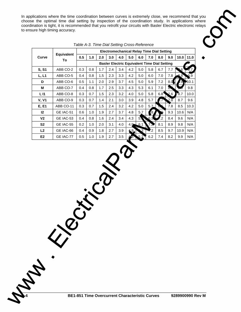
A-4 BE1-851 Time Overcurrent Characteristic Curves 9289900990 Rev M
In applications where the time coordination between curves is extremely close, we recommend that you choose the optimal time dial setting by inspection of the coordination study. In applications where coordination is tight, it is recommended that you retrofit your circuits with Basler Electric electronic relays to ensure high timing accuracy.
Table A-3. Time Dial Setting Cross-Reference Electromechanical Relay Time Dial Setting
0.5 1.0 2.0 3.0 4.0 5.0 6.0 7.0 8.0 9.0 10.0 11.0 Curve Equivalent
To Basler Electric Equivalent Time Dial Setting
S, S1 ABB CO-2 0.3 0.8 1.7 2.4 3.4 4.2 5.0 5.8 6.7 7.7 8.6 9.7
L, L1 ABB CO-5 0.4 0.8 1.5 2.3 3.3 4.2 5.0 6.0 7.0 7.8 8.8 9.9
D ABB CO-6 0.5 1.1 2.0 2.9 3.7 4.5 5.0 5.9 7.2 8.0 8.9 10.1
M ABB CO-7 0.4 0.8 1.7 2.5 3.3 4.3 5.3 6.1 7.0 8.0 9.0 9.8
I, I1 ABB CO-8 0.3 0.7 1.5 2.3 3.2 4.0 5.0 5.8 6.8 7.6 8.7 10.0
V, V1 ABB CO-9 0.3 0.7 1.4 2.1 3.0 3.9 4.8 5.7 6.7 7.8 8.7 9.6
E, E1 ABB CO-11 0.3 0.7 1.5 2.4 3.2 4.2 5.0 5.7 6.6 7.8 8.5 10.3
I2 GE IAC-51 0.6 1.0 1.9 2.7 3.7 4.8 5.7 6.8 8.0 9.3 10.6 N/A
V2 GE IAC-53 0.4 0.8 1.6 2.4 3.4 4.3 5.1 6.3 7.2 8.4 9.6 N/A
S2 GE IAC-55 0.2 1.0 2.0 3.1 4.0 4.9 6.1 7.2 8.1 8.9 9.8 N/A
L2 GE IAC-66 0.4 0.9 1.8 2.7 3.9 4.9 6.3 7.2 8.5 9.7 10.9 N/A
E2 GE IAC-77 0.5 1.0 1.9 2.7 3.5 4.3 5.2 6.2 7.4 8.2 9.9 N/A
www . El
ectric
alPar
tMan
uals
. com

9289900990 Rev M BE1-851 Time Overcurrent Characteristic Curves A-5
Figure A-1. Time Characteristic Curve S, S1, Short Inverse (Similar to ABB CO-2)
www . El
ectric
alPar
tMan
uals
. com
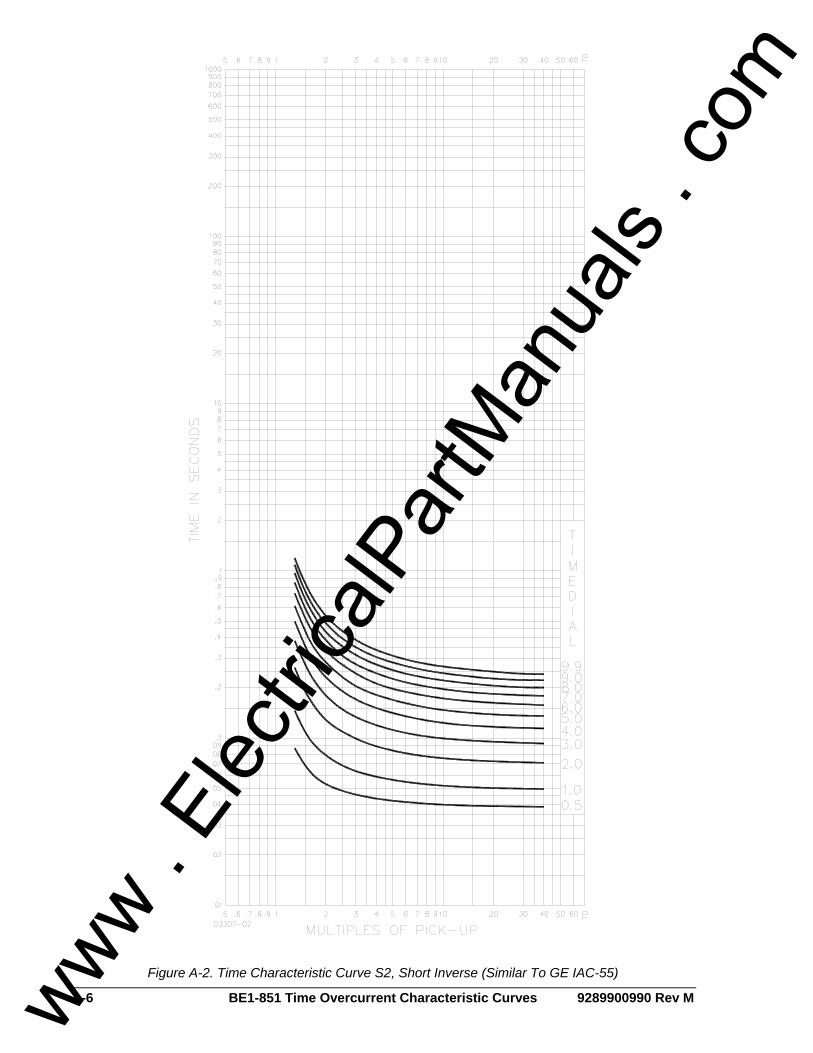
A-6 BE1-851 Time Overcurrent Characteristic Curves 9289900990 Rev M
Figure A-2. Time Characteristic Curve S2, Short Inverse (Similar To GE IAC-55)
www . El
ectric
alPar
tMan
uals
. com

9289900990 Rev M BE1-851 Time Overcurrent Characteristic Curves A-7
Figure A-3. Time Characteristic Curve L, L1, Long Inverse (Similar to ABB CO-5)
www . El
ectric
alPar
tMan
uals
. com

A-8 BE1-851 Time Overcurrent Characteristic Curves 9289900990 Rev M
Figure A-4. Time Characteristic Curve L2, Long Inverse (Similar To GE IAC-66)
www . El
ectric
alPar
tMan
uals
. com

9289900990 Rev M BE1-851 Time Overcurrent Characteristic Curves A-9
Figure A-5. Time Characteristic Curve D, Definite Time (Similar To ABB CO-6)
www . El
ectric
alPar
tMan
uals
. com

A-10 BE1-851 Time Overcurrent Characteristic Curves 9289900990 Rev M
Figure A-6. Time Characteristic Curve M, Moderately Inverse (Similar to ABB CO-7)
www . El
ectric
alPar
tMan
uals
. com

9289900990 Rev M BE1-851 Time Overcurrent Characteristic Curves A-11
Figure A-7. Time Characteristic Curve I, I1, Inverse Time (Similar to ABB CO-8)
www . El
ectric
alPar
tMan
uals
. com

A-12 BE1-851 Time Overcurrent Characteristic Curves 9289900990 Rev M
Figure A-8. Time Characteristic Curve I2, Inverse Time (Similar to GE IAC-51)
www . El
ectric
alPar
tMan
uals
. com

9289900990 Rev M BE1-851 Time Overcurrent Characteristic Curves A-13
Figure A-9. Time Characteristic Curve V, V1, Very Inverse (Similar to ABB CO-9)
www . El
ectric
alPar
tMan
uals
. com

A-14 BE1-851 Time Overcurrent Characteristic Curves 9289900990 Rev M
Figure A-10. Time Characteristic Curve V2, Very Inverse (Similar to GE IAC-53)
www . El
ectric
alPar
tMan
uals
. com

9289900990 Rev M BE1-851 Time Overcurrent Characteristic Curves A-15
Figure A-11. Time Characteristic Curve E, E1, Extremely Inverse (Similar to ABB CO-11)
www . El
ectric
alPar
tMan
uals
. com

A-16 BE1-851 Time Overcurrent Characteristic Curves 9289900990 Rev M
Figure A-12. Time Characteristic Curve E2, Extremely Inverse (Similar to GE IAC-77)
www . El
ectric
alPar
tMan
uals
. com

9289900990 Rev M BE1-851 Time Overcurrent Characteristic Curves A-17
Figure A-13. Time Characteristic Curve A, Standard Inverse
www . El
ectric
alPar
tMan
uals
. com

A-18 BE1-851 Time Overcurrent Characteristic Curves 9289900990 Rev M
Figure A-14. Time Characteristic Curve B, Very Inverse
www . El
ectric
alPar
tMan
uals
. com

9289900990 Rev M BE1-851 Time Overcurrent Characteristic Curves A-19
Figure A-15. Time Characteristic Curve C, Extremely Inverse
www . El
ectric
alPar
tMan
uals
. com

A-20 BE1-851 Time Overcurrent Characteristic Curves 9289900990 Rev M
Figure A-16. Time Characteristic Curve G, Long Time Inverse
www . El
ectric
alPar
tMan
uals
. com
9289900990 Rev M BE1-851 Command Cross-Reference i
APPENDIX B • COMMAND CROSS-REFERENCE TABLE OF CONTENTS
APPENDIX B • COMMAND CROSS-REFERENCE.................................................................................B-1
INTRODUCTION....................................................................................................................................B-1
Tables Table B-1. Miscellaneous Commands.......................................................................................................B-1 Table B-2. Metering Commands................................................................................................................B-1 Table B-3. Control Commands..................................................................................................................B-1 Table B-4. Report Commands...................................................................................................................B-1 Table B-5. Setting Command ....................................................................................................................B-2 Table B-6. Alarm Setting Commands........................................................................................................B-2 Table B-7. General Setting Commands ....................................................................................................B-2 Table B-8. Breaker Monitoring and Setting Commands............................................................................B-3 Table B-9. Programmable Logic Setting Commands................................................................................B-3 Table B-10. User Programmable Name Setting Command ......................................................................B-4 Table B-11. Protection Setting Commands ...............................................................................................B-4 Table B-12. Global Command...................................................................................................................B-4
www . El
ectric
alPar
tMan
uals
. com

ii BE1-851 Command Cross-Reference 9289900990 Rev M
This page intentionally left blank.
www . El
ectric
alPar
tMan
uals
. com

9289900990 Rev M BE1-851 Command Cross-Reference B-1
APPENDIX B • COMMAND CROSS-REFERENCE INTRODUCTION This appendix lists all ASCII commands, command syntax, brief command descriptions, and any corresponding HMI screens. Commands are organized by function in the following groups and tables:
• Miscellaneous (Table B-1) • Metering (Table B-2) • Control (Table B-3) • Report (Table B-4) • Setting (Table B-5) • Alarm (Table B-6)
• General Setting (Table B-7) • Breaker Monitor and Setting (Table B-8) • Programmable Logic Setting (Table B-9) • User Programmable Name Setting (Table B-10) • Protection Setting (Table B-11) • Global (Table B-12)
An entry of x in the HMI Screen column represents multiple entry possibilities such as 0, 1, 2, or 3 for setting groups and 43, 143, 243, or 343 for virtual switches.
Table B-1. Miscellaneous Commands ASCII Command Function HMI Screen
ACCESS[={password}] Read/Set access level in order to change settings. N/A
EXIT Exit programming mode. N/A HELP {cmd} or H {cmd} Obtain help with command operation. N/A
Table B-2. Metering Commands
ASCII Command Function HMI Screen M Read all metered values. N/A M-I[{phase}] Read metered current in primary unit. 3.1 - 3.2
Table B-3. Control Commands
ASCII Command Function HMI Screen CO-{control}[={mode}] Control operation. N/A CS-control[={mode}] Control selection. N/A CS/CO-x43 Control virtual switches. 2.1.1 - 2.1.4 CS/CO-101 Control breaker control switch. 2.2.1 CS/CO-GROUP Control group. 2.3.1 CS/CO-OUTn Control output n. 2.4.1
Table B-4. Report Commands
ASCII Command Function HMI Screen RA[=0] Report/Reset alarm information. 1.3 RA-LGC[=0] Report/Reset logic alarm information. N/A RA-MAJ[=0] Report/Reset major alarm information. N/A RA-MIN[=0] Report/Reset minor alarm information. N/A RA-REL[=0] Report/Reset relay alarm information. N/A RB Read breaker status. 4.3.1 - 4.3.2 RB-DUTY[{phase}[={%duty}]] Read/Set breaker contact duty log. 4.3.2
www . El
ectric
alPar
tMan
uals
. com
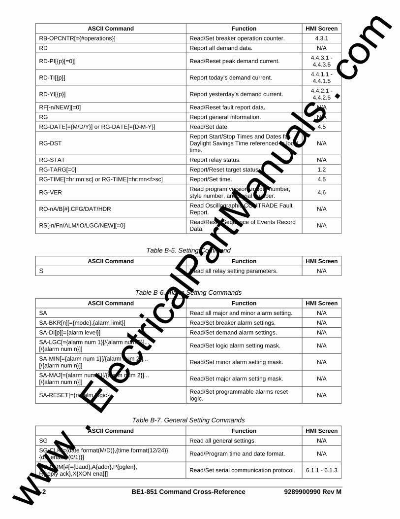
B-2 BE1-851 Command Cross-Reference 9289900990 Rev M
ASCII Command Function HMI Screen RB-OPCNTR[={#operations}] Read/Set breaker operation counter. 4.3.1 RD Report all demand data. N/A
RD-PI[{p}[=0]] Read/Reset peak demand current. 4.4.3.1 - 4.4.3.5
RD-TI[{p}] Report today’s demand current. 4.4.1.1 - 4.4.1.5
RD-YI[{p}] Report yesterday’s demand current. 4.4.2.1 - 4.4.2.5
RF[-n/NEW][=0] Read/Reset fault report data. N/A RG Report general information. N/A RG-DATE[={M/D/Y}] or RG-DATE[={D-M-Y}] Read/Set date. 4.5
RG-DST Report Start/Stop Times and Dates for Daylight Savings Time referenced to local time.
N/A
RG-STAT Report relay status. N/A RG-TARG[=0] Report/Reset target status. 1.2 RG-TIME[=hr:mn:sc] or RG-TIME[=hr:mn<f>sc] Report/Set time. 4.5
RG-VER Read program version, model number, style number, and serial number. 4.6
RO-nA/B[#].CFG/DAT/HDR Read Oscillographic COMTRADE Fault Report. N/A
RS[-n/Fn/ALM/IO/LGC/NEW][=0] Read/Reset Sequence of Events Record Data. N/A
Table B-5. Setting Command
ASCII Command Function HMI Screen S Read all relay setting parameters. N/A
Table B-6. Alarm Setting Commands
ASCII Command Function HMI Screen SA Read all major and minor alarm setting. N/A SA-BKR[n][={mode},{alarm limit}] Read/Set breaker alarm settings. N/A SA-DI[p][={alarm level}] Read/Set demand alarm settings. N/A SA-LGC[={alarm num 1}[/{alarm num 2}]... [/{alarm num n}]] Read/Set logic alarm setting mask. N/A
SA-MIN[={alarm num 1}[/{alarm num 2}]... [/{alarm num n}]] Read/Set minor alarm setting mask. N/A
SA-MAJ[={alarm num 1}[/{alarm num 2}]... [/{alarm num n}]] Read/Set major alarm setting mask. N/A
SA-RESET[={rst alm logic}] Read/Set programmable alarms reset logic. N/A
Table B-7. General Setting Commands
ASCII Command Function HMI Screen SG Read all general settings. N/A SG-CLK[={date format(M/D)},{time format(12/24)}, {dst enable(0/1)}] Read/Program time and date format. N/A
SG-COM[#[={baud},A{addr},P{pglen}, R{reply ack},X{XON ena}]] Read/Set serial communication protocol. 6.1.1 - 6.1.3
www . El
ectric
alPar
tMan
uals
. com
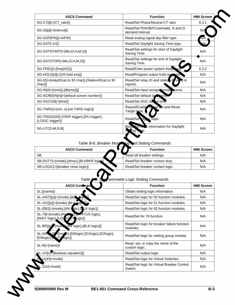
9289900990 Rev M BE1-851 Command Cross-Reference B-3
ASCII Command Function HMI Screen SG-CT[t][={CT_ratio}] Read/Set Phase/Neutral CT ratio. 6.3.1
SG-DI[p][={interval}] Read/Set P(IA/IB/IC/var/watt), N and Q demand interval. N/A
SG-DSP[P/N][=A/F/R] Read analog signal dsp filter type. N/A SG-DST[=1/2] Read/Set Daylight Saving Time type. N/A
SG-DSTSTART[={Mo,D,H,M,O}] Read/Set settings for start of Daylight Saving Time. N/A
SG-DSTSTOP[={Mo,D,H,M,O}] Read/Set settings for end of Daylight Saving Time. N/A
SG-FREQ[={freq(HZ)}] Read/Enter power system frequency. 6.3.2 SG-HOLD[n][={1/0 hold ena}] Read/Program output hold operation. N/A SG-ID[={relayID(up to 30 char)},{StationID(up to 30 char)}]
Read/Set relay ID and station ID used in reports. N/A
SG-IN[#[={r(ms)},{db(ms)}]] Read/Set input recognition/debounce. N/A SG-SCREEN[n][={default screen number}] Read/Set default screen(s). N/A SG-SGCON[={time}] Read/Set SGC output time. N/A
SG-TARG[={x/x/..x},{rst TARG logic}] Report/Enable Target list and Reset Target logic. N/A
SG-TRIGGER[={TRIP trigger},{PU trigger}, {LOGIC trigger}] Read/Set trigger logic. N/A
SG-UTC[=M,R,B] Read/Set UTC information for Daylight Saving Time. N/A
Table B-8. Breaker Monitoring and Setting Commands
ASCII Command Function HMI Screen SB Read all breaker settings. N/A SB-DUTY[={mode},{dmax},{BLKBKR logic}] Read/Set breaker contact duty. N/A SB-LOGIC[={breaker close logic}] Read/Set breaker contact logic. N/A
Table B-9. Programmable Logic Setting Commands
ASCII Command Function HMI Screen SL:[{name}] Obtain setting logic information. N/A SL-x50T[{p}[={mode},{BLK logic}]] Read/Set logic for 50 function modules. N/A SL-x51[{p}[={mode},{BLK logic}]] Read/Set logic for 51 function modules. N/A SL-{f}62[={mode},{INI logic},{BLK logic}] Read/Set logic for 62 function modules. N/A SL-79[={mode},{RI logic},{STATUS logic}, {WAIT logic},{LOCKOUT logic}] Read/Set for 79 function. N/A
SL-BF[{p}[={mode},{INI logic},{BLK logic}]] Read/Set logic for breaker failure function modules. N/A
SL-GROUP[={mode},{D0logic},{D1logic},{D2logic}, {D3logic},{AUTOlogic}] Read/Set logic for setting group module. N/A
SL-N[={name}] Read, set, or copy the name of the custom logic. N/A
SL-VO[x[={Boolean equation}]] Read/Set output logic. N/A SL-{x}43[=mode] Read/Set logic for Virtual Switches. N/A
SL-101[=mode] Read/Set logic for Virtual Breaker Control Switch. N/A
www . El
ectric
alPar
tMan
uals
. com

B-4 BE1-851 Command Cross-Reference 9289900990 Rev M
Table B-10. User Programmable Name Setting Command ASCII Command Function HMI Screen
SN[-{var}[={name},{TRUE label},{FALSE label}] Read/Set user programmable names. N/A
Table B-11. Protection Setting Commands
ASCII Command Function HMI Screen S{g} Read all protection settings. N/A
S{g}-x50T[{p}][={pu(A)}[,{td(m)}]] Read/Set 50T pickup level and time delay.
5.x.1.1 - 5.x.1.6
S{g}-x51[{p}][={pu(A)},{td(m)},{crv}] Read/Set 51 pickup level, time delay, and curve.
5.x.2.1 - 5.x.2.3
S{g}-{f}62[={td1},{td2}] Read/Set 62 time delay. 5.x.3.1 - 5.x.3.2
S{g}-79[#][={td}] Read/Set 79 time delay. 5.x.4.1 - 5.x.4.4
S{g}-79SCB[={step list}] Read/Set 79 Sequence Controlled Block output. 5.x.4.5
SP-BF[={time}[m/s/c]] Read/Set the breaker failure timer setting. 5.5.1.1
SP-CURVE[={A},{B},{C},{N},{R}] Read/Set the user programmable 51 curve parameters. N/A
SP-GROUP{g}=[{sw_time},{sw_level},{ret_time}, {ret_level},{prot_ele}]
Read/Program auxiliary setting group 1 operation. N/A
SP-79ZONE[={zone pickup logic}] Read/Set Zone Sequence Pickup Logic. N/A
Table B-12. Global Command
ASCII Command Function HMI Screen GS-PW[{t}[={password},{com ports(0/1/2)}]] Read or change a password. N/A
www . El
ectric
alPar
tMan
uals
. com
9289900990 Rev M BE1-851 Terminal Communication i
APPENDIX C • TERMINAL COMMUNICATION TABLE OF CONTENTS
APPENDIX C • TERMINAL COMMUNICATION.......................................................................................C-1
WINDOWS® 2000/XP ............................................................................................................................C-1 Windows® Vista......................................................................................................................................C-4
Figures Figure C-1. Connection Description Dialog Box........................................................................................C-1 Figure C-2. Connect To Dialog Box...........................................................................................................C-2 Figure C-3. COM Properties Dialog Box ...................................................................................................C-2 Figure C-4. Properties, Settings Tab.........................................................................................................C-3 Figure C-5. ASCII Setup Dialog Box .........................................................................................................C-4
Tables Table C-1. RS-232 Communication Ports .................................................................................................C-4
www . El
ectric
alPar
tMan
uals
. com

ii BE1-851 Terminal Communication 9289900990 Rev M
This page intentionally left blank.
www . El
ectric
alPar
tMan
uals
. com

9289900990 Rev M BE1-851 Terminal Communication C-1
APPENDIX C • TERMINAL COMMUNICATION WINDOWS® 2000/XP HyperTerminal (provided with Windows® 2000/XP) or other stand-alone software can be used to communicate with a BE1-851 relay. The following instructions are used for configuring HyperTerminal in Windows® 2000/XP to communicate with your BE1-851 relay. The configuration of other stand-alone software is similar. Step 1: Click Start: Highlight Programs, Accessories, Communication, HyperTerminal.
Step 2: Click HyperTerminal to open the folder.
Step 3: Select the file or icon labeled Hypertrm or Hypertrm.exe. Once the program has started, you will be presented with a series of dialog boxes.
Step 4: Dialog Box: Connection Description a. Type the desired file name, for example, BE1-851. See Figure Figure C-1. b. Click “OK”.
Figure C-1. Connection Description Dialog Box
Step 5: Dialog Box: Connect To
a. Click the Connect using: drop-down menu. See Figure C-2. Select COMx, where x is the port you are using on your computer.
b. Click “OK”.
www . El
ectric
alPar
tMan
uals
. com
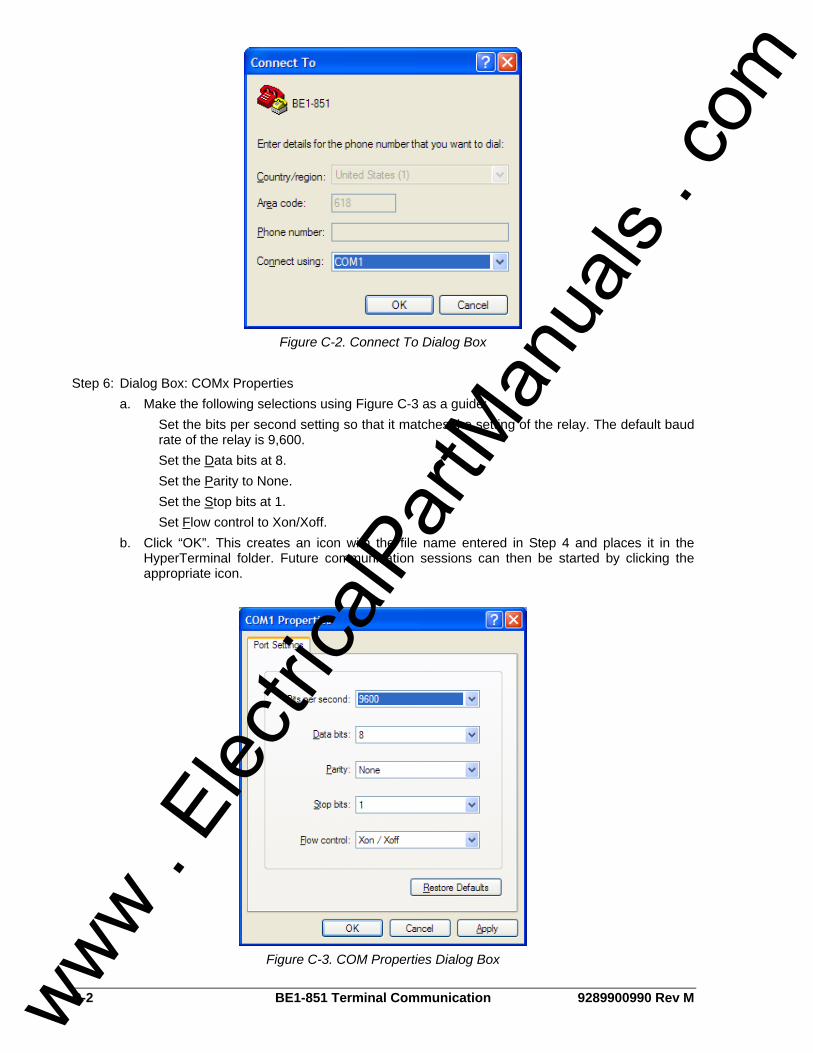
C-2 BE1-851 Terminal Communication 9289900990 Rev M
Figure C-2. Connect To Dialog Box
Step 6: Dialog Box: COMx Properties
a. Make the following selections using Figure C-3 as a guide: Set the bits per second setting so that it matches the setting of the relay. The default baud rate of the relay is 9,600. Set the Data bits at 8. Set the Parity to None. Set the Stop bits at 1. Set Flow control to Xon/Xoff.
b. Click “OK”. This creates an icon with the file name entered in Step 4 and places it in the HyperTerminal folder. Future communication sessions can then be started by clicking the appropriate icon.
Figure C-3. COM Properties Dialog Box
www . El
ectric
alPar
tMan
uals
. com
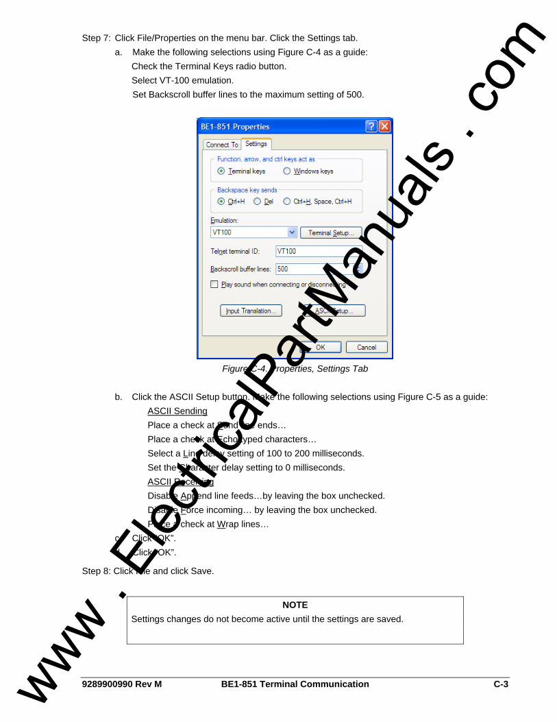
9289900990 Rev M BE1-851 Terminal Communication C-3
Step 7: Click File/Properties on the menu bar. Click the Settings tab. a. Make the following selections using Figure C-4 as a guide:
Check the Terminal Keys radio button. Select VT-100 emulation. Set Backscroll buffer lines to the maximum setting of 500.
Figure C-4. Properties, Settings Tab
b. Click the ASCII Setup button. Make the following selections using Figure C-5 as a guide:
ASCII Sending Place a check at Send line ends…
Place a check at Echo typed characters… Select a Line delay setting of 100 to 200 milliseconds. Set the Character delay setting to 0 milliseconds.
ASCII Receiving Disable Append line feeds…by leaving the box unchecked. Disable Force incoming… by leaving the box unchecked.
Place a check at Wrap lines… c. Click “OK”. d. Click “OK”.
Step 8: Click File and click Save.
NOTE Settings changes do not become active until the settings are saved.
www . El
ectric
alPar
tMan
uals
. com
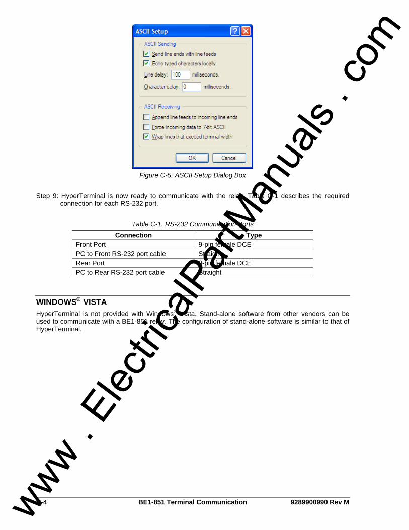
C-4 BE1-851 Terminal Communication 9289900990 Rev M
Figure C-5. ASCII Setup Dialog Box
Step 9: HyperTerminal is now ready to communicate with the relay. Table C-1 describes the required
connection for each RS-232 port.
Table C-1. RS-232 Communication Ports Connection Type
Front Port 9-pin female DCE PC to Front RS-232 port cable Straight Rear Port 9-pin female DCE PC to Rear RS-232 port cable Straight
WINDOWS® VISTA HyperTerminal is not provided with Windows® Vista. Stand-alone software from other vendors can be used to communicate with a BE1-851 relay. The configuration of stand-alone software is similar to that of HyperTerminal.
www . El
ectric
alPar
tMan
uals
. com

ROUTE 143, BOX 269 HIGHLAND, IL 62249 USA
http://www.basler.com, [email protected] PHONE +1 618-654-2341 FAX +1 618-654-2351 www .
Elec
tricalP
artM
anua
ls . c
om