Embed Size (px)
Citation preview

JOURNAL OF PARALLEL AND DISTRIBUTED COMPUTING 15, 49-61 (1992)
Overlapping Connectivity Interconnection Networks for Shared Memory Multiprocessor Systems
BARRY WILKINSON
Department of Computer Science, The University of North Carolina at Charlotte, Charlotte, North Cnrolina, 28223
Overlapping connectivity networks based upon multiple buses, multistage networks, and mesh networks are investiga,*d for shared memory multiprocessor systems. In overlapping connec- tivity networks, each processor in the system has a sphere of influence enclosing memory modules (or other processors) that it can reach directly. The sphere of influence of one processor over- laps the spheres of influence of other processors, and the intercon- nections are localized, affording significant layout advantages. It has been found that the bandwidth of the overlapping connectivity networks based upon multiple buses and multistage networks ex- ceeds that of the corresponding full connectivity network when the range of requests is limited, and similarly the network delay is equal to or less than the corresponding existing full connectivity network (sometimes very significantly). Though the overlapping connectivity mesh network has slightly lower bandwidth than the corresponding full connectivity mesh, it has lower network delay and requires considerably fewer switches. The network delay has been shown to be approximately linear with range of requests for all overlapping connectivity networks presented, both by simula- tion and theoretically. o 1%~ Academic PKSS, IIIC.
1. INTRODUCTION
In a previous paper 1201, a new class of multiprocessor interconnection networks called overlapping connectiv- ity networks was identified. One network within this class was introduced, called the rhombic crossbar net- work. In fact, several other networks can be devised which belong to the overlapping connectivity class. In the present paper, overlapping connectivity networks based upon multiple buses, multistage networks, and mesh networks are investigated for shared memory multiprocessor applications, and compared to existing in- terconnection networks.
The common theme within the overlapping connectiv- ity class is that each processor in the system has a sphere ofinfluence enclosing memory modules (or other proces- sors) that it can reach with a direct path. The sphere of influence of one processor overlaps the spheres of influ- ence of other processors, and the connections within each sphere of influence are localized. A direct path is generally a path in the network between a processor and memory module which uses the minimum number of
switches for the network. The number of switches in a direct path and the length of the path will depend upon the network. In the multiple bus-based networks, a direct path will involve two switches connecting to one shared bus. In a multistage interconnection network, a direct path will involve one pass through the network, i.e., n stages of switching cells for an n-stage network.
In this work, we consider specific examples of overlap- ping connectivity networks where the sphere of influence is a parameter of each network, but note that the sphere of influence could include all memories in the system at one extreme or just one memory at the other extreme. In this way, overlapping connectivity networks could be re- garded as a classification which encompases both fully shared memory architectures and fully distributed mem- ory architectures.
Overlapping connectivity networks are attractive be- cause of two related factors:
l Localized connections aid VLSI layout l Several important applications generate localized
requests.
VLSI layout here refers to both the layout of components within a VLSI chip and the layout of VLSI chips on a board. Interconnection networks which require commun- ication links to extend across the whole system are incon- venient for such large-scale VLSI systems, as are net- works which require a large number of links to cross over each other, because of the limited space and number of interconnection layers. The physical layout constraints are most severe within the chip as a VLSI chip may only have two or three interconnection layers and space is at a premium.
Hypercubes and conventional MINs are often men- tioned as candidates for large scale multiprocessors. However, both have poor layout characteristics. An n- dimensional hypercube has n lines from each node which fan out across the whole network. In a practical system, a hypercube might be laid out with consecutive nodes in a row and parallel lines connecting nodes. Suppose the physical distance between two adjacent nodes laid out in this fashion is one unit. The length of the links from a node would be 1, 2,4, 8, . . . . 2”-’ units. This characteris-
49 0743-7315192 S3.M)
Copyright 0 1992 by Academic Press, Inc. All rights of reproduction in any form reserved.

50 BARRY WILKINSON
tic occurs for all nodes, and hence there are many long links. The interconnections between stages in a MIN such as a Delta or Omega network or other network based upon the perfect shuffle [14] are also of varying lengths and can extend almost from one edge to the oppo- site edge with many crossovers. In contrast, the overlap- ping connectivity networks described here have a fixed (small) length for all interconnections from all nodes.
Partitioning a network into similar subnetworks is also extremely important for layout and scalability. A VLSI chip has a limited number of input/output pins and the pins are not easily reachable from the deep interior of the chip. Ideally, an interconnection network should be such that to increase a system’s size, similar networks can be joined together. Networks such as hypercubes and con- ventional MINs do not have this characteristic. The size of the network (i.e., the number of inputs and outputs handled) inextricably determines the internal intercon- nections in the network. For example, the perfect shuffle common in MINs is defined for a given size of system and differs for different sizes. In contrast, overlapping con- nectivity networks can easily be joined together to en- large the system; the internal interconnection patterns are not related to the size of the system.
Localized connections usually imply that requests pre- sented to the network should also be localized for the best network performance. Well-known application areas which generate localized overlapping memory requests include low-level image processing and the solution of partial differential equations. These applications map onto overlapping connectivity networks well. There are also some important parallel applications in which local- ity generally exists but it may not be regular. For exam- ple, in discrete-event-driven VLSI simulation, different parts of the circuit can be simulated by neighboring pro- cessors using overlapping memory for communication and data storage. VLSI simulation suggests that the inter- connection structure should have the flexibility to handle variable spheres of influence for load sharing.
The types of applications envisioned in this work in- volve almost continuous communication between pro- cessors and locally shared memory for accessing data (and instructions). The quoted applications can be ex- pected to require this communication. Communication between processors themselves is also expected, if possi- ble, via the locally shared memory within the spheres of influence of the two communication processors, and we model this action as memory requests within spheres of influence.
Previous work in the context of regular locality in- cludes that of Reed and Fujimoto [16] who provide an analysis for their spheres of locality in existing intercon- nection networks. Spatial locality of reference in parallel systems is discussed by Feitelson and Rudolph [4]. Gen-
era1 compiler techniques for creating locality when it does not initially exist are described by Pingali and Rogers [ 151. An approach to large-scale interconnection network design is to create hierarchical structures such as system memory/local memory systems, tree net- works, and clustered networks, which have been exten- sively studied [ 1-7, 10, 11, 181. A particular advantage of overlapping connectivity networks compared to hierar- chical networks is uniformity of access; we shall show that the network delay is proportional to the distance to the destination in all cases.
This paper is organized as follows. General character- istics of overlapping connectivity networks are devel- oped in Section 2. Specific overlapping connectivity net- works are given in Section 3, together with their performance compared to existing interconnection net- works using simulation. Section 4 consists of a conclu- sion. In an Appendix, equations are derived for the theo- retical network delay of each of the overlapping connectivity networks.
2. PRELIMINARIES
Overlapping connectivity networks can be divided into two types:
l those without a path in the network between spheres of influence, and
l those with a path in the network between spheres of influence.
Paths between spheres of influence can be provided by cascading overlapping connectivity stages as in the rhom- bic networks [20], or by feedback links in MINs. Over- lapping connectivity networks with paths between spheres enable memory modules outside their sphere of influence to be reached; all memory modules in the sys- tem can be reached.
Overlapping connectivity networks are suitable for ei- ther a circuit-switched mode or a packet-switched mode. In the circuit-switched mode, a path is established be- tween a processor and memory and maintained for the duration of the transfer. None of the physical links within the total path are available to other requests until the transfer has been completed. Circuit switching is often synchronized to a global clock signal which avoids dead- lock problems [19]. In the packet-switched mode, a re- quest is routed through the network and each link is re- leased when the request has passed through the link. Once the request has reached the memory, data are routed back to the processor in the case of a memory read operation. We concentrate upon the (synchronous) circuit-switched mode. Examples of synchronous circuit- switched systems include the Connection Machine [8] and the BBN Monarch [17].

OVERLAPPINGCONNECTIVlTYNETWORKS 51
Three figures of merit for interconnection networks are investigated, namely
l Bandwidth l Network delay l Number of switches
Bandwidth. The bandwidth is the average number of memory requests accepted in a request arbitration cycle. Some other figures of merit can be estimated from band- width, including the probability that a request will be accepted and the execution time [23]. Often requests are considered to be made randomly and independently across the whole system, unless resubmitted after being blocked. In addition, here requests will be considered as being made relative to the processors and not necessarily across the whole networks, because the system is envi- sioned as operating with localized requests when possi- ble. Of course, this is when overlapping connectivity net- works have their greatest benefit.
Overlapping connectivity networks provide local mem- ory for overlapping groups of processors. It is assumed that cache memory is not used. Without cache memory, the shared memory request rate will be very high and approach 100%. Hence, results are reported with a re- quest rate of 100%. A system without separate cache memory avoids cache coherence problems but causes the greatest network contention and is the most severe test for any network. Cache memory would reduce the re- quest rate and alter the request patterns. In general, any reduction in the request rate from the 100% reported here will reduce the network contention and increase the per- centage of submitted requests accepted. The perfor- mance of overlapping connectivity networks then be- come closer to the theoretical maximum achieved by the crossbar switch network. Even though locality of refer- ence may be lost with those requests that are made to the system, cache memory, by reducing the system request rate, actually makes overlapping connectivity networks even more attractive.
Network Delay and Number of Switches. Any inter- connection network will introduce a delay between the processor and memory and clearly this delay should be kept small. The crossbar switch network has only one switch between any input and any output and hence has the least delay of any interconnection network, at the cost of a large number of switches. MINs give a tradeoff between total number of switches and network delay. In existing MINs [9], the network delay is proportional to the number of stages, usually log,N if a x a cells are used with N processors and memories. The number of switches in the network is given by (Na)log,N, counting each a x a cell as having a2 switches. (The overlapping
connectivity MINs given later do not conform to these characteristics.)
Notation. Processors are identified as Pi and memory modules as Mi for 0 5 i < N. The networks generally have wraparound connections so that modulo N arith- metic is required to compute the processor and memory module indices. The modulo N operations are omitted for clarity and should be assumed unless otherwise stated. The symbol Cp is used to denote the sphere of influence, i.e., the number of memory modules that can be reached directly from a processor with a minimum number of switches. The actual range of requests made by a proces- sor, in terms of number of memory modules, is given by R. Note that a distinction is made between the sphere of influence of the network and the actual range of requests. A range of requests greater than the network sphere of influence (i.e., R > 0) can only be supported for net- works which have paths between spheres of influence. Then, requests are passed from one sphere of influence to another to reach distant locations.
Simulation Model. The objective here is to find the general behavior of overlapping connectivity networks when the circuit-switched approach is applied. The same conditions are applied to all networks, including existing networks. As in most studies of this kind, requests are initially generated randomly and independently using a good pseudorandom number generator. Each pseudoran- dom number selects a request from a fixed list of allow- able destinations defined by the range, R, to create the actual request made. A synchronous circuit-switch model is used; a complete path must be established from the processor to the memory for the memory to receive the request. Buffers are not provided at intermediate sites, and if a path is blocked, the whole path must be re- established later. This is fundamentally different from the packet-switched simulation reported elsewhere [20] in which a complete path need not exist at one instant be- cause buffers exist to hold requests being transmitted through the network. Even if a path can be established in the circuit-switched approach, the request is then only accepted if the memory has not already accepted another request. The same request is resubmitted if it is blocked by the network or memory. This corresponds to normal processor operation.
Processors are serviced according to the rotating daisy chain priority scheme. In rotating daisy chain priority, processors are assigned priority in linear descending or- der. After each arbitration cycle, the priority numbers are rotated until the first processor previously serviced be- comes the lowest priority processor. The next processor has the highest priority with all other processors having linearly decreasing priority. This is a fair policy allowing all processors an opportunity to be serviced and is quite easy to implement.

52 BARRY WILKINSON
---
(a)
I M4 M5 M6 M7
UT7
---
two buses shared with another processor, and Q, = 26. Requests could be restricted to one side of the processor so that the buses are not shared. The position of the memory modules and processors can be transposed as in Fig. lc. In both cases, requests can be routed through intermediate processors or memories to reach memories outside their sphere of influence. For a circuit-switched mode, additional switches are required at the processor or memory sites to pass on requests. In the next network, these switches are shown explicitly.
54 pi-3 Pi-2 41 Pi pi+l pi+2 pi+3 pi+4 pi+5
3.2. Overlapping Connectivity Multiple Bus Network
Figure 2 shows how the conventional multiple bus net- work can be modified to provide overlapping connectiv- ity [22]. Buses connect together with bus interfaces (“switches”). Pi can reach M;-h+i through to Mi+h-, , i.e., @ = 26 - 1. This is one less than in the rhombic networks and always an odd number. However, there are multiple paths available, and an increasing number of buses for closer memory modules. In this example, pro- cessors and memory modules occupy alternative sites, Other possibilities exist. For example, memory modules or processors can be formed into separate groups. Con- ventional multiple bus networks [12] can be joined to- gether with crossbar switch networks.
UN ““““”
_-- ___
(4
Notation: l Switch Pi i th processor ..- Bus (shared) Mi i th memory module - Bus (not shared)
FIG. 1. Overlapping connectivity crossbar networks: (a) single network; (b) and (c) multistage networks.
The overlapping connectivity multiple bus network has 2Nb + N switches compared to 2Nb switches in a con- ventional multiple bus network. For comparative pur- poses, suppose there are 256 processors and 256 memory modules. The conventional n-stage 2” x 2” MIN has 4096 switches. This could be compared to an overlapping con- nectivity multiple bus network with eight buses which has 4352 switches. A conventional multiple bus network with eight buses has 4096 switches.
Figure 3 shows representative simulation results for -stage the bandwidth and average number of bus sections re-
quired by requests for a 256 processor/256 memory mod- ule overlapping connectivity multiple bus network. Re- quests are initially generated randomly from processor P; for memory modules LV-,W through Mi+R~~-i ; i.e., re-
3. OVERLAPPING CONNECTIVITY NETWORKS
3.1. Overlapping Connectivity (Rhombic) Crossbar Networks Sphere of influence of Pi
*
A single-stage overlapping connectivity rhombic cross- bar network is shown in Fig. la, and resembles a normal full crossbar switch except that each processor can only connect to a subset of the memory modules in the sys- ___ tern, defining the sphere of influence of the network. The rhombic networks can be cascaded as shown in Fig. lb. The cascaded form of these networks was first described in [20]. There are b buses in each cascaded section, and there are Nb switches in the network. Processor P; can reach memories from Mi-,, through Mi+h-l using one of
P M P M P M P; M; P M P M P M P M I I
---
I I I I I I I 1-1 I I I I I
Notation: l Switch P processor - Bus (shared) M memory module - Bus (not shared) s bus-to-bus switch
FIG. 2. Overlapping connectivity multiple bus network.

OVERLAPPING CONNECTIVITY NETWORKS 53
256
64
;;A" b=4
0 b=2 1 2 4 8 16 32 64 128 256
(a) Range, R
b=l
b=2
b=4
b=8
b= 16
1 2 4 8 16 32 64 128 2i6 (W Range, R
FIG. 3. Performance of overlapping connectivity multiple bus net- work with requests restricted to the range R. Request rate = 100%. (a) Bandwidth; (b) network delay.
quests can be made to both sides of the processor (except R = 1 when only Mi is requested). Results are shown for various numbers of buses and 1 5 R 5 256 in powers of 2.
Requests from P; to Mj are routed to the right if 0 5 (j - i) < N/2; otherwise they are routed to the left. Since each processor has more than one bus that may be free for use, a selection process is necessary to select which bus to use from those free. Processor Pi has connections buses Bi-b+l through Bi, where Bi starts at the immediate left of Pi. The selection process used here is to choose the buses in this order for requests to the left and in reverse order for requests to the right as this ensures that the longest bus in the direction of the request is examined first and then buses of decreasing lengths.
Results for a full crossbar switch network, 28 X 28 Delta MIN and 2” x 28 Omega MIN under similar request conditions are shown for comparison. The Delta network has a maximum bandwidth of N/2 when R = 1 (the iden- tity permutation), because adjacent outputs require some of the same links and hence only one of each pair can be serviced at a time. Also note that the request ranges are even numbers whereas in the overlapping connectivity
multiple bus network, @ is odd. An even range is chosen to be consistent with later networks.
The conventional multiple bus network has maximum bandwidth of b, irrespective of the number of processors, and network delay of 1 (though not shown because this would clutter the figures). We see that the overlapping version always has higher bandwidth even at a full re- quest range, and approaches the full crossbar switch bandwidth with reducing request range. Since the over- lapping connectivity multiple bus network has more si- multaneous paths than a conventional multiple bus net- work, under any request pattern, it will never have lower bandwidth than a conventional multiple bus network. With b = 8, which requires about the same number of switches as the MINs, the bandwidth significantly ex- ceeds that of the MINs when the range is less than 32. The bandwidth is also about the same as a full crossbar switch under these conditions but with a fraction of the number of switches (4352 switches instead of 6.5,536 switches in a 256 x 256 crossbar).
The delay through the network is assumed to be pro- portional to the number of bus sections required by a request (Fig. 3b). The delay can be compared to the num- ber of stages in MINs. Requests in the comparable MINs always encounter eight stages. Requests in the overlap- ping connectivity network encounter fewer bus sections than stages in the MINs in many cases of ranges less than the full range. Even at full range with b = 8, the average number of sections is about the same as the number of stages in the MINs. For nearby destinations, the number of sections is much less than the number of stages and requests would be expected to experience much less de- lay than in the MINs. We can see that the characteristics favor nearby requests at the expense of delays with dis- tant requests. Though a conventional multiple bus ap- pears to have the least delay, 256 processors connecting to each bus would most likely operate with increased delay because of the length of the bus, and may in fact require additional buffers. The theoretical delay is de- rived in the Appendix, and corresponds closely to the simulation. The theoretical delay and number of switches of the network are given in Table I (first and second rows).
To model the situation in which most requests are within a specified range, but some may be outside this range, a second request pattern has been considered as follows. Requests are still made at a total request rate of 100% and across the whole network but divided into two regions, within the range R and outside the range R. The probability that the request is within a range R is given by CY. The remaining requests are made outside this range with a probability (1 - (Y). For example, if (Y = 0.9, 90% of the requests will be made randomly distributed within the range R, and 10% will be made randomly distributed outside this range.

54 BARRY WILKINSON
a = 90% ‘----cm-) ---t, --b,- Delta
96 - cX=50% -I-- r~--*--*--*--~__*-~~=-~ _-__
‘\ . a = 90% ‘I(
m
,
01 I ’ * 4 a 16 32 64 128 256
(a) Range, R
10
l- 1 2 4 8 16 32 64 128 256
lb) Range, R
FIG. 4. Performance of overlapping connectivity multiple bus net- work with requests within a range R at a probability (1. Request rate = 100% and b = 8. (a) Bandwidth; (b) network delay.
Figure 4 compares an 8-bus 256 processor/256 memory overlapping connectivity multiple bus network with the 8-stage Omega MIN using this request pattern. The prob- ability of the request’s being within the specified (bidirec- tional) range is shown at 90% and 50%. (The full range, R = 256, completes the graphs but at this range there is no region to be requested outside the range R.) Now the overlapping multiple bus network performs significantly worse than conventional Omega MIN network. Even a small percentage of requests outside the range R has a deleterious effect on the bandwidth. However, the aver- age network delay (Fig. 4b) is almost always significantly less than the Omega network. If the total request rate to shared memory is reduced from lOO%, as would occur with cache memory, the difference between the networks narrows.
3.3. Overlapping Connectivity Multistage Interconnection Networks
Figure 5 shows two versions of an overlapping connec- in one pass through
tivity MIN [21]. The left and right edges wrap round to W network
form circular paths. The stage-to-stage interconnection FIG. 5. Overlapping connectivity multistage interconnection net- patterns resemble the interconnection patterns of the works; (a) single pass network; (b) multiple pass network.
Gamma network [13] except that the Gamma network has both left and right paths (using 3 x 3 cells). Also, in Fig. 5, the number of stages is not related to the number of networks inputs and outputs as in Gamma and other MINs. It can be chosen to obtain a specific value for @, The overlapping MINs have a form of destination tag routing. The route through the network can be found from the source and destination addresses. For Fig. 5a, the source address, S = s,-, * . 1 sIso, with s,, set to 0, is subtracted from the destination address, D = d,-, . . . dldo, to obtain the routing addrss, T = t,-l . . * tlto (using modulo N arithmetic). Then at stage j, if tj = 0, the even (right cell output) route is taken, otherwise the odd (left cell output) route is taken. The sphere of influence for Pi and Pi+, with i even is from Mi through Mi+Q-l, where @ = 2” and there are n stages.
The network of Fig. 5b is shown with recirculating paths which enable any destination to be reached. Now each processor has a distinct sphere of influence, @, of 2”-’ memory modules; i.e., Pi reaches from Mi through M;++, for all i. Without the feedback paths, the network could be regarded as a MIN version of the overlapping rhombic crossbar network shown in Fig. la. The recircu- lating version, Fig. 5b, could be regarded a MIN version of Fig. lc.
2 x 2 switching cell
--- ---
(4 t *
Sphere of influence Mi
P.

OVERLAPPING CONNECTIVITY NETWORKS 55
64-
“. (a) 1 2 4 8 16 32 64 128 2i6
n-..-A n ‘_
n=7 n=5 n=3
n=3
n=5
n=7
n=9
1Y I I 1 2 4 8 16 32 64 128 256
(b) Range, ff
FIG. 6. Performance of multiple pass overlapping connectivity MIN with requests restricted to a range R. Request rate = 100%. (a) Band- width; (b) network delay.
Figure 6 shows representative simulation results for the network in Fig. 5b with various numbers of stages under similar conditions to the results of the overlapping connectivity multiple bus networks of Fig. 3, except that the requests are from Mi to MI+R-I rather than from Mi-RI2 through Mi+R/2-], because of the nature of the spheres of influence. For intermediate passes through the network before the final pass, the route chosen is along the odd cell outputs until the final stage. Again we see that the bandwidth and network delay are better for local- ized requests. By increasing the number of stages, the performance improves, but more switches are required; there is a tradeoff between cost and performance, which depends upon the expected range of requests.
The theoretical delay is derived in the Appendix, and again corresponds to the simulation. The theoretical de- lay and number of switches of the network are given in Table I.
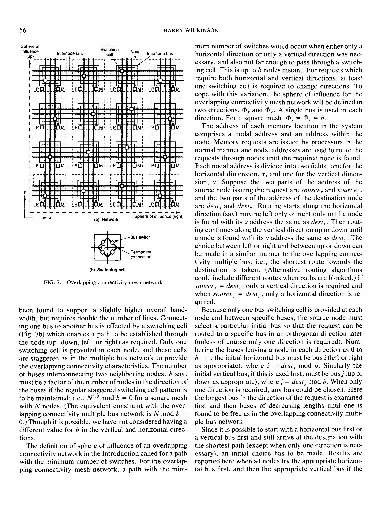
The overlapping multiple bus network extended into two dimensions is introduced in Fig. 7. We will refer to this network as the overlapping connectivity mesh net- work. Each node in the network contains a processor, a memory, and bus interconnection switches. Vertical and horizontal internodal buses interconnect neighboring nodes and are used to route memory requests from pro- cessors to memories. Multiple buses allow simultaneous paths to be established through the nodes and the system to operate in a circuit-switched mode. As with the pre- vious networks, the network connections wrap round at the edges. Each processor and memory is also provided with paths to each of the internodal buses entering the node. Figure 7 shows two intranodal buses within each node for this purpose, though other arrangements are possible for switching between the processors/memory modules and the internodal buses. The intranodal buses correspond to the vertical buses in the overlapping bus networks of Figs. 1 and 2. One intranodal bus is used exclusively by the processor within the node to connect to any one of the internodal buses. The other intranodal bus is used exclusively by the memory within the node to connect to any one of the internodal buses.
The overlapping connectivity MINs seem to possess For the sake of brevity, the internodal buses will be the same layout disadvantage of the processors being on referred to simply as the “buses.” Figure 7 shows three one side of the network and the memories on the other such buses between neighboring nodes. Each bus is bidi- side as other MINs. However the network connections rectional and able to support only one request at a time, are localized and the number of crossovers are generally in either direction. Separate unidirectional buses have
TABLE I Overlapping Connectivity Network Delay and Number of
Switches
Type
Multiple bus:
Delay No. of switches
b=l
R ~ + 0.5 2(2b - 1)
2Ntb + 1)
MIN (feedback)
Mesh:
overlapping
N(6b2 + 8b + I)
N(4b + II)
less than other networks. The parallel nature of the paths also helps layout. The cell inputs can be reversed to re- duce the crossovers in actual construction without affect- ing any characteristics of the network.
3.4. Overlapping Connectivity Mesh Networks
56 BARRY WILKINSON
Sphere of Influence Internode bus
Switching Node lntranode bus
I’--,-------------------
(a) Network Sphere of influence (right)
Bus switch
Permanent connection
(b) Switching cell
FIG. 7. Overlapping connectivity mesh network.
been found to support a slightly higher overall band- width, but requires double the number of lines. Connect- ing one bus to another bus is effected by a switching cell (Fig. 7b) which enables a path to be established through the node (up, down, left, or right) as required. Only one switching cell is provided in each node, and these cells are staggered as in the multiple bus network to provide the overlapping connectivity characteristics. The number of buses interconnecting two neighboring nodes, b say, must be a factor of the number of nodes in the direction of the buses if the regular staggered switching cell pattern is to be maintained; i.e., N”* mod b = 0 for a square mesh with N nodes. (The equivalent constraint with the over- lapping connectivity multiple bus network is N mod b = 0.) Though it is possible, we have not considered having a different value for b in the vertical and horizontal direc- tions.
The definition of sphere of influence of an overlapping connectivity network in the Introduction called for a path with the minimum number of switches. For the overlap- ping connectivity mesh network, a path with the mini-
mum number of switches would occur when either only a horizontal direction or only a vertical direction was nec- essary, and also not far enough to pass through a switch- ing cell. This is up to b nodes distant. For requests which require both horizontal and vertical directions, at least one switching cell is required to change directions. To cope with this variation, the sphere of influence for the overlapping connectivity mesh network will be defined in two directions, @, and ap,. A single bus is used in each direction. For a square mesh, QX = Q+ = b.
The address of each memory location in the system comprises a nodal address and an address within the node. Memory requests are issued by processors in the normal manner and nodal addresses are used to route the requests through nodes until the required node is found. Each nodal address is divided into two fields, one for the horizontal dimension, X, and one for the vertical dimen- sion, y. Suppose the two parts of the address of the source node issuing the request are source, and sourceJ, , and the two parts of the address of the destination node are dest, and desty . Routing starts along the horizontal direction (say) moving left only or right only until a node is found with its x address the same as dest,. Then rout- ing continues along the vertical direction up or down until a node is found with its y address the same as dest, . The choice between left or right and between up or down can be made in a similar manner to the overlapping connec- tivity multiple bus; i.e., the shortest route towards the destination is taken. (Alternative routing algorithms could include different routes when paths are blocked.) If source, = dest, , only a vertical direction is required and when source, = dest,, , only a horizontal direction is re- quired.
Because only one bus switching cell is provided at each node and between specific buses, the source node must select a particular initial bus so that the request can be routed to a specific bus in an orthogonal direction later (unless of course only one direction is required). Num- bering the buses leaving a node in each direction as 0 to b - 1, the initial horizontal bus must be bus i (left or right as appropriate), where i = dest, mod b. Similarly the initial vertical bus, if this is used first, must be busj (up or down as appropriate), wherej = desty mod b. When only one direction is required, any bus could be chosen. Here the longest bus in the direction of the request is examined first and then buses of decreasing lengths until one is found to be free as in the overlapping connectivity multi- ple bus network.
Since it is possible to start with a horizontal bus first or a vertical bus first and still arrive at the destination with the shortest path (except when only one direction is nec- essary), an initial choice has to be made. Results are reported here when all nodes try the appropriate horizon- tal bus first, and then the appropriate vertical bus if the

OVERLAPPING CONNECTIVITY NETWORKS 57
horizontal bus is blocked. A lower bandwidth (typically lo-20% lower) is obtained when only one direction is tried.
A conventional mesh network with multiple buses has been considered for comparison purposes. In this net- work, which we call the full connectivity mesh network, a path is provided via switches from each bus to each of the buses on the other sides of the node rather than limited by the staggered switching cells. The full connectivity mesh network network can be considered as part of the over- lapping connectivity family as each processor can reach five memory modules (one within the node and those in four adjacent nodes) and groups of memory modules overlap in two dimensions.
An appropriate limited range of request- for two-di- mensional mesh networks is for P,,j to request from Mi-v,j-r through M;+r,j+r (in this case, modulo N”? arith- metic), where r is the range of requests in either direction in each dimension; i.e., requests are made to all sides of the processor. For example, if N = 4 x 4 and r = 1, POqO could request any of M3.3 , M3.0, M3,1 , M0.3 , Mo,o, MO. I ,
M1.3, MI,o, and MO.I , nine memories in all. This corre- sponds to the 9-point star stencil, one of the stencils which are used in solving partial differential equations C161. In general, there are (2r + I)* points.
64 0 64 128 192 256
Range, R
,,-,--,,---* ____ *-----* _- - - - - mm--
0 64 126 192 256
(W Range, R
FIG. 8. Performance of overlapping connectivity mesh network with different numbers of buses. Request rate = 100%. (a) Bandwidth; (b)
256 Total requests
Path contention Requests accepted in 192 full connectivity mesh
s I 3 120 B
cc
64
0 1 2 3 4 5 6 7 0
Buses, b
FIG. 9. Source of contention in overlapping connectivity mesh net- work. Request rate = 100% and R = N.
Representative simulation results for a 256-node over- lapping connectivity mesh with different two-dimen- sional request ranges are shown in Fig. 8a and b, where R = (2r + 1)2 nodes for r = 1, 2, 3,4, 5, 6, and 7. The full range, R = N, completes the graphs. Each point along a curve corresponds to the next value of r. As r increases beyond the sphere of influence (a, = @, = b), an abrupt change occurs in the bandwidth and network delay as an additional bus section is required. The same characteris- tic is found in other overlapping connectivity networks (see Figs. 3 and 6). Also of particular interest is that the performance of the network with b = 8 very closely ap- proaches that of a full crossbar switch, in terms of both bandwidth and network delay. It also has many fewer bus sections in a path than the constant eight stages of a conventional 28 x 28 MIN.
We note that the bandwidth of the full crossbar switch network is approximately constant except for small R. This characteristic can easily be established analytically. Given the nature of the request patterns, the range, R, gives not only the number of different destination memo- ries that a source processor can request but also the num- ber of source processors from which a destination mem- ory will receive requests. It follows that the crossbar switch bandwidth is approximately given by N( 1 - (1 - IIR)R) using the well-known probabilistic approach [20], a constant bandwidth for a given value of N except for small R.
Figure 9 shows the breakdown of the source of conten- tion in the overlapping connectivity mesh for networks with different numbers of buses when a full request range (R = N) is made across the whole network. The total number of requests made is fixed given the 100% request rate. The number of requests actually accepted is the bandwidth. The number of requests blocked because at least part of the route is used by other requests is labeled

58 BARRY WILKINSON
path contention. The number of requests reaching the destination memory but not accepted because the mem- ory has already accepted another request is labeled mem- ory contention. Memory contention arises in all net- works, including the full crossbar switch. Also shown for reference is the number of requests accepted in a full connectivity mesh network under the same conditions. Note that while the overlapping connectivity mesh net- work can only have certain values for b (as Nij2 mod b = O), the full connectivity mesh can have any value for b, even greater than the number of nodes in each direction. The bandwidth of the full connectivity mesh network soon converges towards the bandwidth of the full cross- bar switch as the number of buses increases, four buses being sufficient with a 256-node mesh to obtain a band- width close to that of a full crossbar switch network. At that point, there is no path contention. The overlapping connectivity mesh does not converse so rapidly, and still experience slight path contention with eight buses.
The number of switches in the overlapping connectiv- ity mesh network is considerably less than the number of switches in the full connectivity mesh network or full crossbar switch network. There are six switches in each switching cell (see Fig. 7b). Additionally, for b = 3, 16 switches are needed to connect each processor and mem- ory to the buses (see Fig. 7a). In general, there are 4b + 4 such switches. One additional switch is shown on an in- tranodal bus in each node in Fig. 7 for connecting the processor to the memory within the same node, rather than occupying an internodal bus. Hence there are N(4b + 11) switches in the whole network. For b = 8, there are 11,008 switches, more than in the overlapping connectivity multiple bus network described in Section 3.2 or a conventional MIN but still much less than a full crossbar switch network, yet with a network delay less than 2. Also, the interconnection patterns are very con- venient for VLSI layout.
Using the same basic switching design, the full connec- tivity mesh network requires b2 switching cells in each node, 8b switches to connect each processor and mem- ory to the buses, and one switch for the internal proces- sor-memory connection, a total of N(6b2 + 8b + 1) switches in the network. (There is the possibility of using MIN designs at the nodes to reduce the number of switches in the full connectivity mesh.)
The theoretical delay is derived in the Appendix, and corresponds to the simulation. The theoretical delay and number of switches of the networks are given in Table I.
3.5. Other Overlapping Connectivity Networks
There are various other possibilities for creating over- lapping connectivity. For example, a single-link mesh network could be used with nodes being alternately mem- ory or processors. Figure 10 shows an alternative mesh
FIG. 10. Overlapping connectivity single link mesh network.
with some nodal sites having only switches. Each nodal site containing a processor and a memory is labeled as a PE (processing element). This network could be regarded as a two-dimensional version of the rhombic crossbar networks described earlier. It is quite easy to envision a static overlapping connectivity interconnection network with links from one node to more than the usual 4-8 neighboring nodes. This idea could be extended to large numbers of links.
A common characteristic of all of the previous designs is the use of staggered switches to create the overlapping connectivity; an alternative possibility is overlap conven- tional interconnection networks, sharing switching cells. An overlapping connectivity tree network can be created in this manner by arranging trees to have shared branches. Various examples are shown in Fig. 11. Differ- ent levels of overlap can be achieved depending upon the position of overlap. We speculate that other networks can be formed by shared certain internal switching cells of conventional interconnection networks.
4. CONCLUSIONS
In this paper, we have investigated overlapping con- nectivity networks based upon multiple buses and multi- stage interconnection networks for circuit-switched shared memory multiprocessor systems. The bandwidth of these overlapping connectivity networks exceeds that of the corresponding full connectivity network when the range of requests is limited, and similarly the network delay is equal or less than the corresponding existing full connectivity network (sometimes very significantly). We have introduced the overlapping connectivity mesh net-

OVERLAPPING CONNECTIVITY NETWORKS 59
(a)
UN
W
(e)
(f)
c------) Sphere of influence of Pi q Cell shared between + - b Sphere of influence of Pi+1 Pi and Pi+,
FIG. 11. Overlapping connectivity tree networks.
work and presented its performance. Though having slightly lower bandwidth than that the equivalent full connectivity mesh, it has lower network delay and re- quires substantially fewer switches. The network delay has been shown to be approximately linear with range of requests for all overlapping connectivity networks pre- sented, both by simulation and theoretically. The perfor- mance of bus-based and MIN-based overlapping connec- tivity networks are quite comparable in both bandwidth and delay. For requests that span the whole network, existing networks usually perform better. However, ex- isting networks are sometimes difficult, if not impossible,
to construct for very large systems because of the global nature of the interconnection links and separation of pro- cessors from shared memory modules.
The overlapping connectivity tree network has been introduced. Future work includes assessing the perfor- mance of overlapping connectivity networks under spe- cific application areas.
APPENDIX: THEORETICAL NETWORK DELAY
In this Appendix, the theoretical delay in the overlap- ping connectivity networks is developed.
For a network with a sphere of influence of CD, the maximum number of “spheres” within the range of re- quests, R, is given by R/Q. The number of spheres that a request must pass through can be 1, 2, 3, * . ., RI@. Given an equal distribution of requests, the average num- ber of spheres that a request must pass through to reach its destination, q say, is given by
+ 0.5
for unidirectional requests, if R/Q, is an integer. This equation leads to an approximate linear relationship be- tween the range of requests and network delay for each of the overlapping connectivity networks. The delay ex- perienced by requests, 7, is given by
r = k’P, (2)
where k is a constant for the network. For the bus-based networks, k = 1; for the MIN-based networks, k = n, where IZ is the number of stages in the network.
Overlapping Connectivity MZN. For the overlapping connectivity MIN in Fig. 4b, @ = 2”-’ and the delay, 7, is given by
7 = n* = $f + 0.5n. (3)
Overlapping Connectivity Multiple Bus Network. The multiple bus analysis is slightly more complicated. First, the range is given by *R/2. When there is only one bus (b = l), requests to the left must use one more bus than those to the right. In this specific case, we get
RI2
2 c i + RI2 i=l
R 7=
R =,+1. (4)
For b > 1, we can turn to the original equation for q with @ = 2b - 1 to obtain

60 BARRY WILKINSON
R 7 = 326 - 1) + 0.5.
This equation does not take into account of the effect of bus contention’s forcing longer paths to be used. Also, in our case, RI@ is not an integer; this factor can be incor- porated into the previous equations.
Full Connectivity and Overlapping Connectivity Mesh Networks. By considering the nodal coordinate system, the summation of all path lengths from the node (includ- ing a path of zero length for local requests) in a full con- nectivity mesh network is given by
P = % 2 (I4 + IYI) x=x,, y=?‘o
(6)
and
P r= number of different requests ’ (7)
where x and y refer to the x and y co-ordinates of the destination node, the limits being xl and yi in the positive directions, and x0 and y. in the negative directions re- spectively, all relative to x = 0, y = 0. (The formula can be extended to higher dimensional arrays).
When requests extend across the whole network, x0 = y. = N”*/2 - 1, xl = yl = N”*/2, and we obtain P = N3j2/2. Given N different requests from each node, the average network delay, T, is N1’*/2.
For requests below the maximum range and con- strained to the stencil described earlier, x0 = y. = -r, xl = y1 = +r. Then (6) reduces to
P = 2r(r + 1)(2r + 1) (8)
and
2r(r + 1) r ‘= 2r+l =‘+2r+l - = r + 0.5 for r P 1. (9)
Note that the approximate linear relationship between r and r reappears.
In the overlapping connectivity mesh network, fewer buses will be needed than in the full connectivity net- work. For example moving along the positive x direction first say, for 0 < (dest, - sourcex) 5 6, one bus section is required. For b < (dest, - source,) 5 2b, two buses are required. In general, the number of buses is given by [(dest, - source,)/b]. Moving along the positive y direc- tion afterwards, although there is no choice in the bus used, the number of buses is also given by [(dest, - sourcey)lb]. Hence, in general, the summation of all path
lengths from the node is given by
(10)
For requests constrained to the stencil x0 = y. = -r, xl = y, = +r, and assuming that r/b is an integer, (10) reduces to
P = 2r(2r + l)(i + 1)
and hence
2r(rlb + 1) 7= (2r+1) ’
(11)
(12)
Equation (11) is obtained after recognizing that apart from x = 0 or y = 0, the mesh can be divided into groups of b x b nodes which have the same path length from the source node. Note that (12) reduces to (9) for b = 1 (full connectivity mesh network).
ACKNOWLEDGMENTS
This work was supported in part by funds from the Foundation of the University of North Carolina at Charlotte and from the State of North Carolina.
1.
2.
3.
4.
5.
6.
7.
8.
9.
10.
REFERENCES
Chen, W.-T., and Sheu, J.-P. Performance analysis of multistage interconnection networks with hierarchical requesting model. IEEE Trans. Comput. 37, 11 (Nov. 1988). 1438-1442. Choudhary, A. N., and Patel, J. H. Performance evaluation of clusters of NETRA: An architecture for computer vision systems. Proc. 1990 International Conference on Parallel Process. Pennsyl- vania State Univ. Press, PA, 1990, pp. 494-497. Dandamudi, S. P., and Eager, D. L. Hierarchical interconnection networks for multiprocessors. IEEE Trans. Comput. 39, 6 (June 1990), 786-797.
Feitelson, D. G., and Rudolph, L. Distributed hierarchical control for parallel processing. IEEE Comput. 23, 5 (May 1990), 65-77. Gajski, D. Cedar-A large scale multiprocessor. Proc. 1983 Znter- national Conference on Parallel Processing. IEEE Comput. Sot. Silver Spring, MD, 1983, pp. 524-529. Gehringer, E. F., Siewiorek, D. P., and Segall, Z. Parallel Process- ing: The Cm* Experience. Digital Press, 1987. Handler, W., Bode, A., Tritsch, G., Henning, W., and Volkert, J. A tightly coupled and hierarchical multiprocessor architecture. Comput. Phys. Commun. 37, 1-3 (July 1985), 87-93. Hillis, D. The Connection Machine. MIT Press, Cambridge, MA, 198.5. Hwang, K., and Briggs, F. A. Computer Architecture and Parallel Processing. McGraw-Hill, New York, 1984. Hwang, K., Tseng, P.-S., and Kim, D. An orthogonal multiproces-

OVERLAPPING CONNECTIVITY NETWORKS 61
11.
12.
13.
14.
15.
16.
17.
18.
19.
SOT for parallel scientific computation. IEEE Trans. Comput. 38, 1 (Jan. 1989) 47-61. Irani, K. B., and Naji, A. R. Performance study of a cluster shared- memory multiprocessor. International Conference on Supercom- puting. Assoc. Comput. Mach., New York, 1988, pp. 304-314. Lang, T., Valero, M., and Fiol, M. A. Reduction of connections for multibus organizations. IEEE Trans. Comput. C-32, 8 (Aug. 1983). 707-716. Parker, D. S., and Raghavendra, C. S. The Gamma network. IEEE Trans. Comput. C-33, 4 (April 1984). 367-373. Patel, J. H. Performance of processor-memory interconnections for multiprocessors. IEEE Trans. Comput. C-30, 10 (Oct. 1981), J71- 780.
Pingali, K., and Rogers, A. Compiling for locality. Proc. 1990 Znter- national Conference on Parallel Processing. Pennsylvania State Univ. Press, PA, 1990, pp. 142-146. Reed, D. A., and Fujimoto, R. M. Multicomputer Networks Mes- sage-Based Parallel Processing. MIT Press, Cambridge, MA, 1987. Rettberg, R. D., Crowther, W. R., Carvey, P. P., and Tomlinson, R. S. The monarch parallel processing hardware design. IEEE Comput. 23, 4 (April 1990), 18-30. Stumm, M., and Zhou, S. Algorithms implementing distributed shared memory. IEEE Comput. 23, 5 (May 1990), 54-64. Szymanski, T. A comparison of circuit and packet switching in a fiber-optic hypercube. Proc. 1990 International Conference on Par- allel Processing. Pennsylvania State Univ. Press, PA, 1990, pp. 296-300.
20. Wilkinson, B. Cascaded rhombic crossbar interconnection net- works. J. Parallel Distrib. Comput. 10, I (Sept. 1990). 96-101.
21. Wilkinson, B. Comparative Performance of Overlapping Connec- tivity Multiprocessor Interconnection Networks. The Computer Journal 34, 3 (June 1991), 207-214.
22. Wilkinson, B. Multiple Bus Network with Overlapping Connectiv- ity. IEE Proceedings Pt. E: Computer.? and Digital Techniques 138, 4 (July 1991), 281-284.
23. Yen, D. W. L., Patel, J. H., and Davidson, E. S. Memory interfer- ence in synchronous multiprocessor systems. IEEE Trans. Com- put. C-31, 11 (Nov. 1982), 1116-1121.
BARRY WILKINSON received the B.Sc. degree (with 1st class hon- ors) in electrical engineering from the University of Salford, England, in 1969, and M.Sc. and Ph.D. degrees from the University of Manchester (Department of Computer Science), England, in 1971 and 1974 respec- tively. He is currently an associate professor in the Department of Computer Science at the University of North Carolina at Charlotte and has research interests including parallel processing and multiprocessor architectures. He has previously held faculty positions at Brighton Polytechnic, England (1984-1987), State University of New York, Col- lege at New PaItz (1983-1984) University College, Cardiff, Wales (1976-1983), and the University of Aston, England (1973-1976). He is the author of Computer Peripherals (with D. Horrocks, Hodder and Stoughton, 2nd ed., 1987), Digital System Design (Prentice-Hall, 1987). and Computer Architecture: Design and Performance (Prentice- Hall, 1991).
Received December 13, 1990; accepted September 20, 1991