Embed Size (px)
Citation preview
OVERSIDE WORK RAIL SYSTEM
SIZE 1
Installation, Use and Servicing ManualPart No B10465- iss.1 (Feb. 2016)
GB
LEWMAR OVERSIDE WORK RAIL SYSTEM SIZE 1
1. Introduction
2. Description and Purpose
3. Rating
4. System Specification
5. System Components
6. Part Numbers
7. Installation
8. Use
9. Maintenance and Thorough Examination
10. External Documents
11. System Component Drawings
12. Warranty
Contents

OVERSIDE WORK RAIL SYSTEM SIZE 1 - B10465 iss.1 | 3
Please read these instructions carefully before installing, operating or servicing this equipment. These instructions MUST be provided to the user of this equipment. The user must read and understand the instructions before using this equipment. Manufacturer’s instructions must be followed to ensure correct use and maintenance of this equipment. Alterations or misuse of this equipment, or failure to follow these instructions, may result in a fall or failure to arrest a fall leading to serious injury or death.
PLEASE RETAIN THESE INSTRUCTIONS
1 - IntroductionThank you for choosing Lewmar. Lewmar products are world renowned for their quality, technical innovation and proven performance. With a Lewmar product you will be provided with many years of outstanding service.
Important information about this manualThroughout this manual, you will see safety and product damage warnings. You must follow these warnings carefully to avoid possible injury or damage.
2 - Description and Purpose
⚠ WARNING!
The Lewmar Overside Work Rail System is a personal suspension system for the lifting, lowering and traversing of persons performing maintenance operations. It enables safe access whilst working at height. It is not to be used for lifting equipment or any other purpose.
This system is CE-certified and has been successfully tested against the requirements in European standard EN 795 Class D editions 1996 and 2012. It has also been successfully tested against the requirements in Lewmar Test specification TS-LEW-15, which was specifically developed for testing personal suspension systems, including rescue, and specifies requirements well in excess of those found in EN 795.
The system consists of aluminium track sections which are joinable to form a continuous span of rail. This is fixable to a structure in the horizontal plane, whether that structure is part of a sea vessel, building, steelwork, air or land vehicle or the like and the course of the rail follows the contour of the structure to which it is fixed. Cars can be engaged on and can slide along the rail. End-stops are fixed to the ends of the rail span to prevent inadvertent disengagement of the cars.
A person may lift or lower themselves in the vertical plane by attaching a lifting-lowering device and rope to the shackle of a car, together with a seat or support harness. Also, they may traverse horizontally from one position to another along the span of the rail by virtue of the car’s sliding capability.
Consequently, suspended access can be gained to any point below the rail span. This can be extremely useful in situations where conventional access methods such as ladders and platforms cannot be utilised.
⚠ Lewmar tracks and car are not compatible with those of any other manufacture. Only use CE Certified Lewmar products (Page 6) for overside working.

4
GB
End Stops
M8 fastener holes
Typical locking hole
Car
Rail
Locking Device
Carriage Link
Shackle
Main system components
Fall-Arrest Rope
Fall-Arrest Rope
Optional car and link for use as a tool carrier
Lifting-Lowering Rope
Lifting-Lowering Rope
Cars

OVERSIDE WORK RAIL SYSTEM SIZE 1 - B10465 iss.1 | 5
A device permits the locking of the car to any of the locking holes along the rail, so that when lowering or lifting in the vertical plane, the car does not inadvertently slide along the rail in response to lowering or lifting movement, enabling the person to maintain stability and to control their position.
A second car, which is joined to the main car, provides the attachment point for a fall-arrest system. The fall-arrest system prevents a fall to the ground, substantial platform, water or other substance should the lifting-lowering device or rope fail. Use of the fall-arrest system necessitates the wearing of a full body safety harness by the worker.
The rail is also tested and rated for rescue purposes - to allow a second person to lower themselves from an additional pair of cars on the track in order to rescue a worker whohas become incapacitated, or whose fall has been arrested and cannot get back to a place of safety on their own.
An additional single car can also be used to secure a small tool bag and containers of cleaning agents, to assist in any maintenance work.
3 - Rating
In normal operation the system is designed for use by one person with a mass,(including clothing and attached equipment), not in excess of 125 kg. No more than one person may be connected to a two-car assembly at any one time. The fall-arrest system must be connected to the car with the spring loaded locking plunger and the lifting-lowering system must be connected to the other car.
In order to assist in the rescue of a person whose fall has been arrested by the fall-arrest system, or has become incapacitated and is not able to self-recover, a second person may suspend themselves and descend to render assistance from an additional pair of cars. The system has been tested and has been rated for this situation, so that two persons, each not in excess of 125 kg, may be attached to the rail in an emergency/rescue situation.

6
GB
4 - System specificationA system will comprise the following elements:
4.1 Track rail
The rail is low profile and is extruded from 6000 series aluminium, with a hard anodised black finish. The track rail is secured with M8 countersunk A4-70 stainless steel screws on a 100mm pitch, with car stop plunger holes spaced 50mm apart from the first fixing, on a100mm pitch. The track rail may be one piece or a multiple oftracks installed in-series, using a joiner insert (2991 5076). Only use designated Lewmar Overside working tracks.
4.2 One tandem sliding car assembly (two short cars and link plate)
The car is machined from 6000 series aluminium, with a hard anodised black finish. It has recirculating Torlon ball bearings for free running, low friction performance and low maintenance. The anchor point shackle is forged from 316 grade stainless steel of 8mm diameter, andis free to pivot in a 180 degree arc, 90 degrees each side of the centre line.
The basic tandem car has two anchor point shackles, one on each car - one anchor point for personal suspension (overside working) and the second anchor point for fall-arrest.
DO NOT CUT TRACKS

OVERSIDE WORK RAIL SYSTEM SIZE 1 - B10465 iss.1 | 7
4.3 Two End stop
Installed one each at both track rail ends, with 2 x M8 countersunk fixings (supplied), through pre-drilled
holes.
One car body houses the spring plunger assembly - a spring loaded stainless steel plunger with a lock up/down feature for eitherfree running (‘locked up’ position) or engagement with thetrack to prevent lateral movement, (‘locked down’position). The locked up position is achieved by pulling the plunger up and twisting. The locked down position is achieved by positioning the plunger over a locating hole on rail (pre-drilled on a 100 mm pitch) and twisting to allow plunger to engage hole.
An optional third car can be attached to the tandem car assembly using a link plate kit (2991 3316), for the purpose of carrying tools (Tool Service Car).
Plunger down, car locked to railPlunger up and locked, car free to move along rail
Plunger up, car ready to move to new position

8
GB
4.4 - Product Features
2000
sho
wn
(tra
ck a
vaila
ble
in 2
m, 3
m a
nd 4
m le
ngth
s (c
an a
lso
be jo
ined
)
3en
d st
opov
erha
ng
265
130
sing
le c
ar66
6610
0.0
100.
050
.0
Ø9.
0
Ø9.
5
for M
8 C'
SK
BLIN
D, F
OR
PLU
NGE
R
66
(400
)In
clud
ing
optio
nal e
quip
men
t car
rier
2937
1232
0BK
S
z1 O
/S ra
il tr
ack
2m jo
in x
229
3712
321B
K
Sz1
O/S
rail
trac
k 2m
end
x1
join
x1
2937
1232
2BK
S
z1 O
/S ra
il tr
ack
2m e
nd x
2
2937
1233
0BK
S
z1 O
/S ra
il tr
ack
3m jo
in x
229
3712
331B
K
Sz1
O/S
rail
trac
k 3m
end
x1
join
x1
2937
1233
2BK
S
z1 O
/S ra
il tr
ack
3m e
nd x
2
2937
1234
0BK
S
z1 O
/S ra
il tr
ack
4m jo
in x
229
3712
341B
K
Sz1
O/S
rail
trac
k 4m
end
x1
join
x1
2937
1234
2BK
S
z1 O
/S ra
il tr
ack
4m e
nd x
2
See
deta
il A
Typi
cal d
rillin
gD
etai
l A
TRA
CK J
OIN
ER H
D29
9150
76-
Sz1
box
trac
k jo
inin
g in
sert
HD
(x1)
LIN
K PL
ATE
2991
3316
- Sz
1 O
/S c
ar li
nk p
late
ADD
ITIO
NA
L CA
RBl
ack
2991
3310
BK-
Sz1
O/S
wor
k ca
r sin
gle
shac
kle
plun
ger
2991
3311
BK-
Sz1
O/S
wor
k ca
r sin
gle
shac
kle
3 end
stop
over
hang
TAN
DEM
CA
RBl
ack
2991
3313
BK-
Sz1
O/S
wor
k ca
r dou
ble
TRA
CKBl
ack
END
STO
PBl
ack
2991
5075
BK-
Sz1
O/S
RAI
L IM
PACT
EN
D

OVERSIDE WORK RAIL SYSTEM SIZE 1 - B10465 iss.1 | 9
5 - System Components
Sz1 Over Side Work Car Double29913313BK (Black)
Sz1 Over Side Work Car Single Shackle Plunger29913310BK (Black)
Sz1 Over Side Work Car Single Shackle 29913311BK (Black)
Sz1Over Side Rail Impact End29915075BK (Black)
Sz1 Over Side Car Link Plate Kit29915075
Sz1 Joiner Insert HD 29915075
Track293712320BK / 293712342BK (Black)

10
GB
6 - Sz1 Overside Work Rail Product Part Numbers
Part No. Black Description SWL (kg)
Length (mm)
Width (mm) Weight (g)
29913313BK Sz1 O/S Work Car Double 125 265 66 966
29913310BK Sz1 O/S Work Car Singl Shackle Plunger 125 130 66 476
29913311BK Sz1 O/S Work Car Single Shackle 125 130 66 402
29915075BK Sz1 O/S Rail Impact End 66 66 125
29913316 Sz1 O/S Car Link Plate Kit - - - 88
29915076 Sz1 Joiner Insert HD - - - 29
293712320BK Sz1 O/S Rail Track 2 Mtr Join x2 2000 23 518
293712321BK Sz1 O/S Rail Track 2 Mtr Endx1 Join X1 2000 23 518
293712322BK Sz1 O/S Rail Track 2 Mtr End x2 2000 23 518
293712330BK Sz1 O/S Rail Track 3 Mtr Join x2 3000 23 1038
293712331BK Sz1 O/S Rail Track 3 Mtr Endx1 Join X1 3000 23 1038
293712332BK Sz1 O/S Rail Track 3 Mtr End x2 3000 23 1038
293712340BK Sz1 O/S Rail Track 4 Mtr Join x2 4000 23 2081
293712341BK Sz1 O/S Rail Track 4 Mtr Endx1 Join X1 4000 23 2081
293712342BK Sz1 O/S Rail Track 4 Mtr End x2 4000 23 2081
⚠ Lewmar tracks and car are not compatible with those of any other manufacture. Only use CE Certified Lewmar products (Page 6) for overside working.

OVERSIDE WORK RAIL SYSTEM SIZE 1 - B10465 iss.1 | 11
7.- Installation
The Lewmar overside work rail system should only be installed by competent organizations, that is organiza-tions with designated persons who are suitably trained or qualified by knowledge and practical experience to enable the required installation tasks to be carried out properly, (BS 7883: 2005). Installation personnel should follow the guidance within BS 7883: 2005 (Code of practice for the design, selection, installation, use and main-tenance of anchor devices conforming to BS EN 795),when installing the system.
In order to provide the maximum benefits of protection and access ergonomics for the user, the Lewmar overside work rail system has been designed to be installed in bespoke configurations to match the features of the workplace structure. Consequently an on-site survey is required in every instance in order to determine the design criteria relevant to installing the system. No attempt should be made to install the system without first establishing the working requirements of the personnel who will have to use the system, the risks that the system will have to counter, and the most appropriate solution to the problem. See also design notes below.
The Lewmar overside work rail system has been primarily designed to be fixed to structures by bolting through steel, aluminium or composite structural materials. Where it is intended to attach to concrete or other masonry substrates, it is recommended that box or channel section is first fixed to the substrate to provide a mounting surface for the rail. See also design notes below.
7.1 Strength of Structure
The Lewmar overside work rail system should only be fixed to structures if the strength of the structure has been assessed and has been found strong enough to support a load of 25 kN. This load caters for potential loadings that could be applied in service at the associated factors of safety in the following situations:
(i) for a single user of the maximum rated mass of 125 kg both for personal suspension and fall-arrest use;
(ii) for 2-person rescue purposes - where a second user (Rescuer) of the maximum rated mass of 125 kg suspend themselves from an additional pair of cars on the rail in order to recover a user whose fall has been arrested or who is incapacitated in some way.
General Notes:
Design Notes:
7.2 Determining Access Point to Rail
It is important to remember that the user is not fully protected from a fall until the connection with the fall-arrest system is made. In planning the configuration of the system, adequate consideration should always be given to the positioning of the rail in this respect. The access point to the rail should always be in a safe area, i.e. free from fall hazards. Where this cannot be achieved, a secondary means of fall protection needs to be installed to give protection whilst bridging the gap between the access route and the rail system.
7.3 Distance required to arrest fall
The rail should be installed as to ensure that there is sufficient space below the installation position for a fall to be safely arrested in, without the user striking the ground or other obstacle. Advice can be obtained from the manufacturer of the fall arrest system that will be attached to the car in use. The safest conditions prevail where the rail is installed above the highest point the user can access.

12
GB
7.4 Rope protection
The rail should be positioned so that when personal suspension and fall-arrest systems are attached, ropes are not caused to run over sharp or abrupt edges in normal use or when pulled taut under load.
7.5 Corrosion protection
Consideration should be given to the material used in the structure to ensure that it does not cause corrosion in either fastener, structure or rail system. Isolation between the fastener, structure or rail system may be required. Rail and end stop fasteners should be installed with anti corrosion compound under heads, for example Duralac or Tef-Gel.
7.6 Track rail orientation
When viewed from the front elevation, the installed rail attitude needs to be as near horizontal and level as possible, running parallel to walkways, ground level or waterline as appropriate.
The track can be installed in an overhead mounted or side mounted configuration

OVERSIDE WORK RAIL SYSTEM SIZE 1 - B10465 iss.1 | 13
7.7 Track Rail Installation
1. The track rail has been designed and tested when secured with M8 countersunk socket head stainless steel screws, of grade A4-70 to DiN 7991, spaced on a 100 mm pitch. Only use these fasteners to secure the rail to the structure. Apply Tef-Gel or Duralac anti-corrosion paste to underside of head. Secure with stainless steel washers and locknuts such as Nyloc or Aerotight or if using plain nuts secure in position with a threadlocker, such as Loctite 222.
2. The minimum length of track rail that can be secured is 2.0 m, using a total of 21 M8 A4-70 screws. Do not cut tracks to smaller lengths.
3. If constructing track rails of multiple lengths in series, precise alignment of track rails is critical for the ef-ficient and smooth running of cars, and is achieved through use of the correct track joiner insert, part number 29915076.
4. Install tracks one at a time. To join, holding a pin through the joiner insert centre hole, push the insert into the secured track until the pin is touching the track end. The insert will now be centrally positioned about the join. Retain the pin in position whilst offering the second track end, withdrawing the pin as the end pushes against the pin. Push the track fully home once the pin is removed.
Only join track ends that have a fixing hole (countersink) near the end. Do not join track ends drilled for end stop fixing (M8 tapped thread), as there is reduced support near the end due to the drilling pattern.
⚠ WARNING!
⚠ DO NOT CUT TRACKS
⚠ ONLY USE PATENT LEWMAR SUPPLIED TRACKS
14
GB
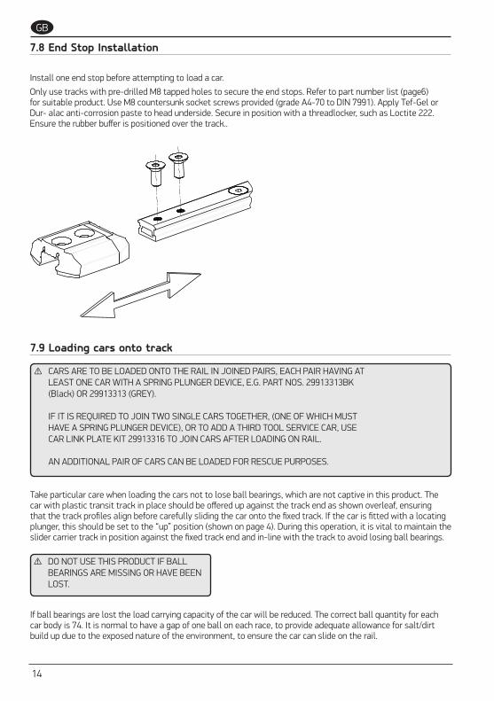
7.8 End Stop Installation
Install one end stop before attempting to load a car.
Only use tracks with pre-drilled M8 tapped holes to secure the end stops. Refer to part number list (page6) for suitable product. Use M8 countersunk socket screws provided (grade A4-70 to DIN 7991). Apply Tef-Gel or Dur- alac anti-corrosion paste to head underside. Secure in position with a threadlocker, such as Loctite 222. Ensure the rubber buffer is positioned over the track..
7.9 Loading cars onto track
Take particular care when loading the cars not to lose ball bearings, which are not captive in this product. The car with plastic transit track in place should be offered up against the track end as shown overleaf, ensuring that the track profiles align before carefully sliding the car onto the fixed track. If the car is fitted with a locating plunger, this should be set to the “up” position (shown on page 4). During this operation, it is vital to maintain the slider carrier track in position against the fixed track end and in-line with the track to avoid losing ball bearings.
⚠ DO NOT USE THIS PRODUCT IF BALL BEARINGS ARE MISSING OR HAVE BEEN LOST.
⚠ CARS ARE TO BE LOADED ONTO THE RAIL IN JOINED PAIRS, EACH PAIR HAVING ATLEAST ONE CAR WITH A SPRING PLUNGER DEVICE, E.G. PART NOS. 29913313BK(Black) OR 29913313 (GREY).
IF IT IS REQUIRED TO JOIN TWO SINGLE CARS TOGETHER, (ONE OF WHICH MUSTHAVE A SPRING PLUNGER DEVICE), OR TO ADD A THIRD TOOL SERVICE CAR, USECAR LINK PLATE KIT 29913316 TO JOIN CARS AFTER LOADING ON RAIL.
AN ADDITIONAL PAIR OF CARS CAN BE LOADED FOR RESCUE PURPOSES.
If ball bearings are lost the load carrying capacity of the car will be reduced. The correct ball quantity for each car body is 74. It is normal to have a gap of one ball on each race, to provide adequate allowance for salt/dirt build up due to the exposed nature of the environment, to ensure the car can slide on the rail.
OVERSIDE WORK RAIL SYSTEM SIZE 1 - B10465 iss.1 | 15
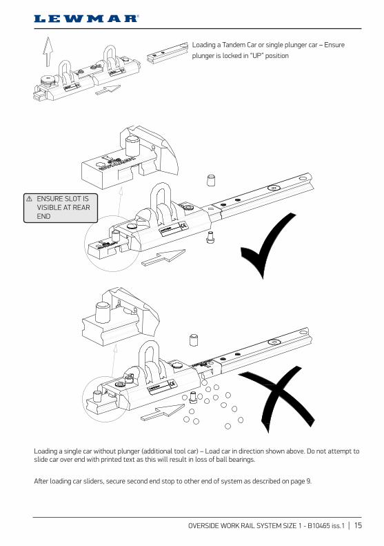
Loading a Tandem Car or single plunger car – Ensure
plunger is locked in “UP” position
Loading a single car without plunger (additional tool car) – Load car in direction shown above. Do not attempt to slide car over end with printed text as this will result in loss of ball bearings.
After loading car sliders, secure second end stop to other end of system as described on page 9.
⚠ ENSURE SLOT IS VISIBLE AT REAR END

16
GB
7.10 Fitting car link plate kit (No. 2991 3316)
In order to join two or more cars together, 29913313, 29913311, 29913310, use car link plate kit 29913316. This consists of 2 x M8x17mm button head screws 24310099 and 1 x car link 24310097. Note that at least one car should have a spring plunger device.
ITEM PART No DESCRIPTION QTY1 24310097 Sz1 O/S CAR LINK 12 24310099 M8x17 B/H SKT FV520B 2
NOTES, 1, WEIGHT 88 g 2, CARS USE WITH LEWMAR Sz1 OVERSIED WORKING PRODUCT, PART NUMBERS 2991 3313(BK) 2991 3311(BK) 2991 3310(BK) 3, -IMPORTANT - REFER TO LEWMAR USER MANUAL BEFORE INSTALLATION AND OPERATION
Position cars to be joined adjacent to each other on the track/rail. Ensure shackle pin cap head retaining screws are secure.
Position link plate over car bodies, using cap head screws as locator guides. Chamfered screw cut-outs are to face upwards. Apply thread-locker (Blue Loctite 243 or equivalent) to plate retaining screws and tighten to a torque of 9.0Nm (+/-1.0Nm)
Check that the joined cars run freely and that all screws are secure.

OVERSIDE WORK RAIL SYSTEM SIZE 1 - B10465 iss.1 | 17
7.11 Post-installation checks
With the spring plunger locked in the up position, check that the cars can slide along the whole length rail of the rail system without being impeded, particularly over rail joints. Check that the spring plunger can engage into locating holes in rail at various locations to lock the car positively to rail.
Ensure that all the countersunk fasteners are fitted to the rail sections and are secure (at 100 mm centres). Ensure that both end-stops are fitted with fasteners secured.
Secure a system rating plate (see below) near to the likely access / egress point on the rail system (part No. B15320).
REFER TO APPENDIX A FOR INSTALLATION DOCUMENTATION
LEWMAR OVERSIDE WORK RAIL SYSTEM PLATEREMOVE ALL BURRS AND SHARP EDGES
Unauthorised use, manufacture or reproduction
In whole or in part is prohibited
12
A
34
5
B C D E
67
8
ORIGINAL SIZE A4
10
REFERENCE SCALE IN MM
91
0
0 20
A
30 40 50
B C D E
12
34
56
78
91
0
FIRST ANGLE PROJECTION
70.0
60.0
PA
RT
No.
B
1532
0
DATEMOD No.REVISIONISSUE
03-Sep-15HW6358PROTOTYPE
PART No.
B15320MODEL NAME: B15320
FINISH
SCALE 2:1
TOLERANCES (UNLESS STATED)LINEAR 0,2
ANGULAR 1,0
TITLE
Sz1 SYSTEM PLATEDATE 03-Sep-15
MATERIAL
DRN G PUGHALL DIMENSIONS IN mm
www.lewmar.com
TS-LEW-15
LEWMAR LIMITEDSOUTHMOOR LANE, HAVANT
HAMPSHIRE, ENGLAND PO9 1JJ
MAX WORKING LOAD ON RAILIN NORMAL OPERATION
MAX WORKING LOAD ON RAILIN EMERGENCY/RESCUEOPERATION
ONE USER NOT INEXCESS OF 125 Kg
TWO USERS EACHNOT IN EXCESSOF 125 Kg
THIS EQUIPMENT IS DESIGNED FOR THELIFTING AND LOWERING OF PERSONS AND
IS NOT TO BE USED FOR THE LIFTINGAND LOWERING OF MATERIALS OR EQUIPMENT
Sz1 OVERSIDE WORK RAIL SYSTEM
BS EN 795
REFER TO INSTRUCTIONS FOR USE
FULL SIZESCALE 1:1

18
GB
8 - Use
8.1 Instructions and Training
These instructions MUST be provided to the user of this equipment.
Please read these instructions carefully before using the Lewmar Overside Work Rail System. Instructions must be followed to ensure correct use. Other manufacturer’s instructions relating to personal lifting/lowering/rope access and fall-arrest equipment that users intend to connect to the Lewmar Overside Work Rail System should also be followed. Misuse or failure to follow instructions may result in a fall or failure to arrest a fall leading to serious injury or death.
⚠ WARNING
⚠ IT IS STRONGLY RECOMMENDED THAT ALL USERS OF THE LEWMAR OVERSIDE WORK RAIL SYSTEM ARE FULLY TRAINED IN HOW TO USE IT IN THE WORKPLACE. SUCH TRAINING INCLUDES BEING AWARE OF THE OPERATING CHARACTERISTICS, APPLICATION LIMITS, AND THE CONSEQUENCES OF IMPROPER USE. TRAINING IS ALSO RECOMMENDED CONCERNING OTHER PERSONAL LIFTING/LOW-ERING/ROPE ACCESS AND FALL-ARREST EQUIPMENT THAT IS INTENDED TO BE CONNECTED TO THE LEWMAR OVERSIDE WORK RAIL SYSTEM. THE USER MUST NEVER RELY SOLELY ON ONE ATTACH-MENT POINT FOR PERSONAL SUSPENSION / ROPE ACCESS WORK. A SECOND ATTACHMENT POINT MUST BE USED FOR THE ATTACHMENT OF A FALL-ARREST SYSTEM, WHICH IS TO BE USED AT THE SAME TIME. THE FALL ARREST SYSTEM MUST ALSO BE CONNECTED DIRECTLY TO THE USER’S FULL BODY HARNESS SO THAT, IN THE EVENT OF FAILURE OF THE LIFTING-LOWERING SYSTEM, A FALL IS PREVENTED.
8.2 System Guidance
The Lewmar overside work rail system is intended to be used with, but is not supplied with the following equipment:
(1) Personal lifting and lowering equipment or rope access equipment designed and tested to allow a user connected to the overside work rail system to lift or lower themselves in order to gain access to a given area whilst in suspension. Lewmar do not endorse specific equipment but recommend that equipment selected should conform to any of the recognised European standards which cover such equipment, e.g: BS EN 341: 2011, BS EN 1496: 2006, BS EN 12841: 2006 or equivalent specification.
(2) Fall-arrest equipment designed and tested to automatically arrest a fall when connected to the overside work rail system and user. Lewmar do not endorse specific equipment but recommend that equipment se-lected should conform to any of the recognised European standards which cover such equipment, e.g: BS EN 353-2: 2002, BS EN 360: 2002. It is important that the fall-arrest equipment used is able to limit arrest force to a maximum of 6 kN.
(3) Connectors designed and tested to connect the items of equipment in (1) and (2) to the overside work rail system and to the harness / seat in (4), e.g. karabiners and hooks with self closing and self-locking gates. Lewmar do not endorse specific equipment but recommend that equipment selected should conform to any of the recognised European standards which cover such equipment, e.g: BS EN 362: 2004 or equivalent specification.

OVERSIDE WORK RAIL SYSTEM SIZE 1 - B10465 iss.1 | 19
(4) Harnesses and Seats designed and tested to hold the body of the user in relative comfort when connected to the items of equipment in (1) and (2). Lewmar do not endorse specific equipment but specify / recommend the following:
‣ Use of fall-arrest system in (2) necessitates the wearing of a full body harness by the user. This should conform to BS EN 361: 2002 or equivalent specification. The full body harness may incorporate a sit harness conforming to BS EN 813: 2008 in its construction, for the connection of the lifting-lowering rope at the front waist attachment point. Note that a sit harness on its own cannot be used for arresting a fall.
‣ A bosun’s chair or full seat should be used in preference to being in suspension in a harness, particularly if the access and work activity will take considerable time. Motionless suspension in a harness can cause an intolerance in that the blood in the circulatory system may pool in the legs which may lead to fainting and eventual cardiac failure.
Note that a full body harness should be worn and be connected to the fall-arrest system irrespective of the type of chair or seat used.
EXAMPLES OF SUSPENDED CHAIRS
Other guidance can be found in:
BS 8437: 2005 - Code of practice for the selection, use and maintenance of personal fall protection systems and equipment for use in the workplace
BS 7985: 2009 - Code of practice for the use of rope access methods for industrial purposes
IRATA ICOP: 2014 International code of practice for industrial rope access

20
GB
8.3 Pre-use Cautions and Warnings
Fall-arrest systemsWhen connecting a fall-arrest system to the Lewmar overside work rail system, always use a type that limits the maximum arrest force on the user in a fall situation to 6 kN.
MedicalUsers with medical disorders should contact their doctors for advice prior to using any fall arrest system. Age and fitness are factors that can affect a person’s ability to withstand the braking force applied during an arrested fall. After the fall the suspended person, (who may be suffering from injury), has then to be rescued. As such, the weight of the person has to be supported by the straps of the harness, perhaps for a considerable period, depending on the speed of rescue. This can have an adverse effect on circulation and breathing. Personnel having any reason to doubt their condition should not work at height until they consult their doctor. Conditions to be concerned about are:
‣ Fainting and dizzy spells, fits and blackouts
‣ High blood pressure, circulatory / heart problems
‣ Back / muscular-skeletal problems
‣ Any recurring injuries
‣ Breathing difficulties
‣ Undergoing a course of medical treatment which may or may not include medication
‣ The effects of alcohol consumption from the previous 24 hour period
The list is not exhaustive.
‣ Pregnant women and minors are advised not to work at height
RatingThe following rating must never be exceeded.
In normal operation the system is designed for use by one person with a mass, (including clothing and attached equipment), not in excess of 125 kg. No more than one person may be connected to a two-car assembly at any one time.
In order to assist in the rescue of a person whose fall has been arrested by the fallarrest system, or has become incapacitated and is not able to self-recover, a second person may suspend themselves and descend to render assistance from an additional pair of cars. The system has been tested and has been rated for this situation, so that two persons, each not in excess of 125 kg, may be attached to the rail in an emergency/rescue situation.
Modifications and repairAlways consult Lewmar or their authorised representatives if your installation needs any form of modification. Never attempt to repair, alter or tamper with the system. Always entrust repair work to an authorised organisation. The Lewmar Overside Work Rail System is CE certified and any unauthorised alterations will contravene the certification and could result in dangerous consequences for users.
Lifting MisuseDo not use the rail and cars to lift equipment or goods. This action may cause unseen damage to the system and may create additional hazards.

OVERSIDE WORK RAIL SYSTEM SIZE 1 - B10465 iss.1 | 21
Rope DamageRopes can be damaged and weakened by contact with sharp edges, abrasive surfaces, direct heat and chemicals. Always exercise extreme care when working in circumstances where ropes could be inadvertently damaged.
Making ConnectionsConnections should be made to the shackle of the rail car using a connector conforming to BS EN 362. Connection to the shackle by making a knot is forbidden. Connections should always be done in a place of safety - there can be no protection from falling until the connection is properly made.
ContaminationDo not allow foreign matter to come between the rail and car. Paints, bitumen, mud, cement, and other building or cleaning fluids could adversely affect the performance of the system. In particular, where work using substances containing strong acid, alkali, or chemical concentrations is to be conducted adjacent to the rail, adequate precautions should be implemented to prevent contact of these substances. The same precautions are required if processes such as welding will be taking place.
Car RemovalCars are intended to remain on the rail as part of the installation. They are not meant to be removed on a day-to-day basis. They should only be removed on an occasional basis for examination purposes. On those occasions a plastic transit track should be used to remove the car, in order to prevent a loss of the ball bearings.
If ball bearings are lost, no attempt should be made to reload car onto rail as ball bearing loss will weaken the car’s ability to sustain loads.
RescueAfter an arrested fall a user remains suspended in the harnessIt might be possible to reach part of the structure in order to regain support, but usually the user has to wait for rescue. During this time the weight of the user has to be supported by the straps of the harness. This can have a worsening effect on the circulatory, breathing and metabolic performance of the body. It is therefore imperative that the suspension time is kept to a minimum and that the user is brought back to a position of safety as soon as it is possible by rescue or other means.
The importance of having a rescue plan to deal with such emergencies cannot be overemphasized when involved with work at height. Such a plan might include rescue equipment, personnel, and training as necessary.
A sensible strategy is to employ two workers for the task at height, so if one falls, the other can assist in the rescue, or can summon help. High visibility clothing, whistles, and personal alarms are all items worthy of consideration.
Prior to any work being carried out, Lewmar always recommend the fitment of an additional pair of cars to the rail for rescue purposes. In the event of an emergency, the rescue cars can be moved into a position above the person to be rescued, and equipment can be attached to facilitate the rescue process. The Rescuer can then suspend themselves using their own lifting-lowering / rope access system and fall-arrest system and descend to render assistance from the rescue cars. The system has been tested and has been rated for this situation, so that two persons, each not in excess of 125 kg, may be attached to the rail in an emergency/rescue situation.
22
GB
DO NOT USE the Lewmar Overside Work Rail System if any of the following have occurred or are apparent visually:
‣ The system has been subjected to fire
‣ The system has been contaminated with a chemical / substance
‣ The system has been contaminated with weld splatters or has been damaged by another process involving extreme heat
‣ The system has sustained a fall arrest
‣ The system has been damaged by a falling object or other incident
‣ The cars do not glide properly
‣ The system appears defective in any manner and / or needs servicing. If in doubt do not use suspect equipment.
If any of the above have occurred the system should be labelled as unfit for use. Lewmar Ltd or their authorised representatives should be contacted for further action.
⚠ WARNING
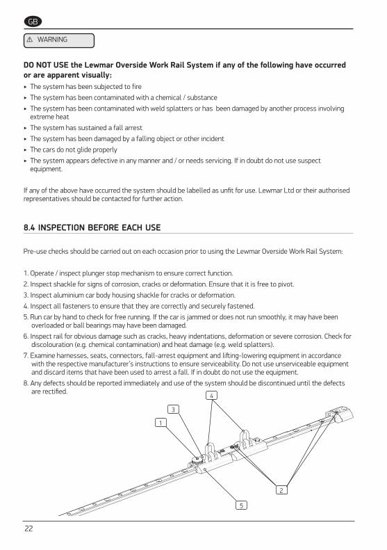
8.4 INSPECTION BEFORE EACH USE
Pre-use checks should be carried out on each occasion prior to using the Lewmar Overside Work Rail System:
1. Operate / inspect plunger stop mechanism to ensure correct function.
2. Inspect shackle for signs of corrosion, cracks or deformation. Ensure that it is free to pivot.
3. Inspect aluminium car body housing shackle for cracks or deformation.
4. Inspect all fasteners to ensure that they are correctly and securely fastened.
5. Run car by hand to check for free running. If the car is jammed or does not run smoothly, it may have been overloaded or ball bearings may have been damaged.
6. Inspect rail for obvious damage such as cracks, heavy indentations, deformation or severe corrosion. Check for discolouration (e.g. chemical contamination) and heat damage (e.g. weld splatters).
7. Examine harnesses, seats, connectors, fall-arrest equipment and lifting-lowering equipment in accordance with the respective manufacturer’s instructions to ensure serviceability. Do not use unserviceable equipment and discard items that have been used to arrest a fall. If in doubt do not use the equipment.
8. Any defects should be reported immediately and use of the system should be discontinued until the defects are rectified.
4
5
3
2
1

OVERSIDE WORK RAIL SYSTEM SIZE 1 - B10465 iss.1 | 23
MAKING CONNECTIONSWhen making connections between equipment and the Lewmar Overside Work Rail System car, use only karabiners and hooks that conform to BS EN 362, in particular
‣ Items that provide protection against inadvertent opening of the gate, for example by means of a screwed sleeve or an automatic locking device, and
‣ Items with a captivated rope termination, to prevent the rope eyelet from moving over the gate (see figure below).
The fall-arrest system is to be connected to the car with the spring loaded plunger stop and the lifting-lowering system is to be connected to the other car, (see figure below). Do not connect both systems to the same car. Do not use the Lewmar Overside Work Rail System without a fall-arrest system.
In addition, ensure that the gate of the karabiner faces outward, so that it does not bear against the car.
Fall-arrest and lifting-lowering systems connected to cars with captivated karabiner/hook
(karabiner/hook gates facing outwards)
Gate
Fall-ArrestSystem
Lifting-LoweringSystem
⚠ WARNING

24
GB
ConnectionsThe connections between the respective components within the lifting-lowering system and lifting-lowering system fall-arrest system gate fall-arrest system, including those to the bosun’s chair or seat, and to the user’s full body harness, should be done in accordance with the respective manufacturer’s instructions.
When making connections within the system, including to the car, connectors used should be of a design and size such that once the connection is made, the connector can rotate freely in the attachment point and so that it is free to align with the direction of loading. Once the connection is made the gate should be able to fully close and lock. Some examples of correct and incorrect connections are shown in the diagram below.
Examples of correct and incorrect connectionsConnections A, B, and C are examples of correct connection. The remainder show incorrect connections.
‣ In view E the rope is choke hitched through the connector and should not be used like this.
‣ In view F the connector gate cannot close due to its size and shape and should not be used like this.
‣ In view G the rope is tied around the attachment and should not be used like this.
‣ In view H the connector cannot rotate freely in the attachment point and should not be used like this.
‣ In view I the rope is bearing on the connector’s gate mechanism and should not be used like this.
‣ In view J the connector is bearing on a rough edge and should not be used like this.
‣ In views K & L connectors are positioned such that they would be bent over an edge if subjected to a fall load and should not be used like this.

OVERSIDE WORK RAIL SYSTEM SIZE 1 - B10465 iss.1 | 25
Plunger down, car locked to railPlunger up and locked, car free to
move along rail
Plunger up, car ready to move to new
USING THE SPRING-LOADED PLUNGER STOPWhen traversing across the rail the plunger stop needs to be set in the “locked up” position, to allow the cars to slide along the rail in response to user movement. The locked up position is achieved by pulling the plunger up and twisting, (see diagram below). Once the desired work position is reached for descending, the plunger stop is to be set in the “locked down” position. This locks the cars to the rail and prevents any lateral movement of the car on the rail. This ensures that the user can maintain their axis of descent from a fixed point on the rail irrespective of descending and ascending movement and, in the event of an arrested fall, it minimises any pendulum swinging motion. The locked down position is achieved by positioning the plunger over a locating hole on rail (pre-drilled on a 100 mm pitch) and twisting to allow plunger to engage hole. The car should be wiggled on the rail to make sure that it is locked in place.

26
GB
9 - Maintenance and Thorough Examination
REGULAR MAINTENANCE ‣ Wash cars regularly with fresh water. Car ball races should be flushed frequently by applying water and mild detergent to the track, and rolling the car back and forth to work the solution through the races, to remove salt and dirt build-up. Rinse with fresh water.
‣ Do not apply spray lubricants as these will prevent the ball bearings from recirculating, and over time will attract dirt/salt build up.
SIX-MONTHLY THOROUGH EXAMINATIONIn accordance with the Lifting Operations and Lifting Equipment Regulations 1998 and The Merchant Shipping and Fishing Vessels (Lifting Operations and Lifting Equipment) Regulations 2006, a thorough examination is to be carried out at six-monthly intervals.
The Lewmar overside work rail system should only be examined by competent organizations, that is organizations with designated persons who are suitably trained or qualified by knowledge and practical experience to enable the required tasks to be carried out properly. Such persons should have knowledge of examination requirements, recommendations and instructions issued by the manufacturer. They should be capable of identifying and assessing the significance of defects, should initiate the corrective action to be taken and should have the necessary skills and resources to do so. A competent person may need to be trained by the manufacturer or authorised representative due to product complexity or innovation, or where safety critical knowledge is needed in the dismantling, reassembly or examination of the equipment, and may need to have that training updated due to product modifications and upgrades.
This examination is a formal examination of the entire rail system and its connection to the structure for damage, degradation, wear and loose fastenings. Results are to be recorded in a log (Appendix B). All cars are to be removed and examined and checked for functionality, as per the instructions below / Appendix C. Where a fall has been arrested, the cars should be destroyed and discarded and replaced with new items. The section of rail and fasteners where the arrested fall took place should be removed, destroyed and discarded. The structure should be examined particularly in the region of the fall, for damage. Once the structure has been assessed and has been found to be satisfactory, a new section of rail and fasteners can be fitted.

OVERSIDE WORK RAIL SYSTEM SIZE 1 - B10465 iss.1 | 27
1. Remove x2 button head link plate retaining screws to release link plate.
2. Carefully slide car bodies off the transit track, one at a time over a container to ensure ball bearings are not lost. Examine ball bearings for signs of wear (grooves) or de formation (flats). Do not re-use damaged balls. Damaged balls may indicate overload- ing or high wear, in which case the assembly should be returned to Lewmar for inspection.
3. Remove the socket head cap screw taking care not to lose the spring washer. Stand the car on end and tap gently to release the shackle pivot rod from the car body. Inspect the shackle, pin and car body for signs of corrosion, wear or cracking, which, if found, the complete assembly should be returned to Lewmar for inspection. Apply grease to shackle pivot rod during re-assembly. Apply Loctite threadlocker to all screw threads during re-assembly.
4. The plunger pin cap assembly is riveted to the car body and cannot be removed. Inspect the underside where the sleeve interfaces with the car body for corrosion. Operate the pin up and down to check that the sleeve is tight. Smear some grease to the angled surfaces of the protruding plunger pin and operate the pin up/down, to work the grease into the sleeve. If the pin is tight to operate it may have been bent due to overloading. If the sleeve is loose it may have been damaged due to overloading. In both cases, the assembly should be returned to Lewmar for inspection.
5. Track End stops – Examine threaded holes in track for corrosion. Examine end stop fixing screws and track holes for signs of impact damage. If found, consult Lewmar before using the system.
‣ REFER TO APPENDIX B FOR SERVICE DOCUMENTATION
‣ REFER TO APPENDIX C FOR SIXMONTHLY THOROUGH EXAMINATION PROCEDURE

28
GB
‣ APPENDIX A: INSTALLATION PLAN (External Document Provided )
‣ APPENDIX B: Service Record (External Document Provided )
‣ APPENDIX C: Six-Monthly Thorough Examination Procedure (External Document Provided )
10 - External Document

OVERSIDE WORK RAIL SYSTEM SIZE 1 - B10465 iss.1 | 29
11 - System Component Drawings
Item Description QTY
1 8mm PETERSEN SHACKLE (O/S) 2
2 Sz1 SHACKLE PIN (O/S) 2
3 Sz2 PLUNGER KIT 1
4 M8 THREADED INSERT (O/S) 3
5 Sz1 O/S CAR LINK 1
6 M8x17 B/H SKT FV520B 2
7 Sz1 TRANSIT CARRIER 300mm 1
8 Sz2 PLUNGER SLEEVE RING 1
9 Sz1 O/S WORK SHACKLE CAR m/c 2
10 SOCKET HD CAP SCREW 2
11 SPRING WASHER 2
12 SKIFFY COVER CAP 039 0008 220 03 1
13 Sz1 CAR CE LABEL 4
14 DIA 1/4” TORLON BALL 148
15 D-LOCTITE 243 (NUTLOCK) 1
11.1 Sz1 Over Side Work Car Double
ITEM PART No DESCRIPTION QTY1 24000047 8mm PETERSEN SHACKLE (O/S) 22 24000048 Sz1 SHACKLE PIN (O/S) 23 24003459 Sz2 PLUNGER KIT 14 24004871 M8 THREADED INSERT (O/S) 35 24310097 Sz1 O/S CAR LINK 16 24310099 M8x17 B/H SKT FV520B 27 24310145 Sz1 TRANSIT CARRIER 300mm 18 24310146 Sz2 PLUNGER SLEEVE RING 19 24310095BK Sz1 O/S WORK SHACKLE CAR m/c 210 B0748 SOCKET HD CAP SCREW 211 B1230-A4 SPRING WASHER 212 B12908 SKIFFY COVER CAP 039 0008 220 03 113 B15136 Sz1 CAR CE LABEL 414 B1732 DIA 1/4" TORLON BALL 14815 B2602 D-LOCTITE 243 (NUTLOCK) 1
NOTES, 1, DESIGN LOADS SWL (MAXIMUM WORKING LOAD) : 125 Kg 2, WEIGHT 966 g 3, TRACK USE HIGH LOAD Sz1 TRACK, PART NUMBERS 293712320BK - 2 METRE w/ JOIN x2 293712321BK - 2 METRE w/ JOIN x1 END x2 293712322BK - 2 METRE w/ END x2 293712330BK - 3 METRE w/ JOIN x2 293712331BK - 3 METRE w/ JOIN x1 END x2 293712332BK - 3 METRE w/ END x2 293712340BK - 4 METRE w/ JOIN x2 293712341BK - 4 METRE w/ JOIN x1 END x2 293712342BK - 4 METRE w/ END x2 (HD TRACK JOINING INSERT 29915076) FIXINGS - M8 COUNTERSUNK ON 100,0 PITCH, USE GRADE A4-70 OR HIGHER 4, -IMPORTANT - REFER TO LEWMAR USER MANUAL BEFORE INSTALLATION AND OPERATION
APPLYGREASE
APPLY GREASE
15
15
RIVET PLUNGERTO CAP ONASSEMBLY
APPLY BLUE LOCTITE
APPLY BLUE LOCTITE
1
2 3
4
5 6
7
9
10
11
12
8 13
14
APPLY GREASE

30
GB
Item Description QTY
1 8mm PETERSEN SHACKLE (O/S) 1
2 Sz1 SHACKLE PIN (O/S) 1
3 Sz2 PLUNGER KIT 1
4 M8 THREADED INSERT (O/S) 1
5 Sz2 PLUNGER SLEEVE RING 1
6 Sz1 BALL LOADER 1
7 Sz1 O/S WORK SHACKLE CAR m/c 1
8 SOCKET HD CAP SCREW 1
9 SPRING WASHER 1
10 Sz1 CAR CE LABEL 2
11 DIA 1/4” TORLON BALL 74
12 D-LOCTITE 243 (NUTLOCK) 1
13 M6 KNURLED NUT NYLON 66 2
14 M6x10 SLT PAN HD NYLON 66 2
11.2 Sz1 Over Side Work Car Single Shackle Plunger
ITEM PART No DESCRIPTION QTY1 24000047 8mm PETERSEN SHACKLE (O/S) 12 24000048 Sz1 SHACKLE PIN (O/S) 13 24003459 Sz2 PLUNGER KIT 14 24004871 M8 THREADED INSERT (O/S) 15 24310146 Sz2 PLUNGER SLEEVE RING 16 25003346 Sz1 BALL LOADER 17 24310095BK Sz1 O/S WORK SHACKLE CAR m/c 18 B0748 SOCKET HD CAP SCREW 19 B1230-A4 SPRING WASHER 110 B15136 Sz1 CAR CE LABEL 211 B1732 DIA 1/4" TORLON BALL 7412 B2602 D-LOCTITE 243 (NUTLOCK) 113 B4240 M6 KNURLED NUT NYLON 66 214 B4679 M6x10 SLT PAN HD NYLON 66 2
NOTES,
1, DESIGN LOADS SWL (MAXIMUM WORKING LOAD) : 125 Kg
2, WEIGHT 476 g
3, TRACK USE HIGH LOAD Sz1 TRACK, PART NUMBERS
293712320BK - 2 METRE w/ JOIN x2 293712321BK - 2 METRE w/ JOIN x1 END x2 293712322BK - 2 METRE w/ END x2
293712330BK - 3 METRE w/ JOIN x2 293712331BK - 3 METRE w/ JOIN x1 END x2 293712332BK - 3 METRE w/ END x2
293712340BK - 4 METRE w/ JOIN x2 293712341BK - 4 METRE w/ JOIN x1 END x2 293712342BK - 4 METRE w/ END x2
(HD TRACK JOINING INSERT 29915076)
FIXINGS - M8 COUNTERSUNK ON 100,0 PITCH, USE GRADE A4-70 OR HIGHER
4, -IMPORTANT - REFER TO LEWMAR USER MANUAL BEFORE INSTALLATION AND OPERATION
APPLY GREASEAPPLY GREASE
12
APPLY BLUE LOCTITE
APPLY GREASE
RIVET PLUNGERTO CAP ONASSEMBLY
1
3
11
2
4 5
6
7
8
9
10
13
14

OVERSIDE WORK RAIL SYSTEM SIZE 1 - B10465 iss.1 | 31
Item Description QTY
1 8mm PETERSEN SHACKLE (O/S 1
2 Sz1 SHACKLE PIN (O/S) 1
3 M8 THREADED INSERT (O/S) 1
4 Sz1 BALL LOADER 1
5 Sz1 O/S WORK SHACKLE CAR m/c 1
6 SOCKET HD CAP SCREW 1
7 SPRING WASHER 1
8 SKIFFY COVER CAP 039 0008 220 03 1
9 Sz1 CAR CE LABEL 2
10 DIA 1/4” TORLON BALL 74
11 D-LOCTITE 243 (NUTLOCK) 1
12 M6 KNURLED NUT NYLON 66 2
13 M6x10 SLT PAN HD NYLON 66 2
11.3 Sz1 Over Side Work Car Single Shackle
ITEM PART No DESCRIPTION QTY1 24000047 8mm PETERSEN SHACKLE (O/S) 12 24000048 Sz1 SHACKLE PIN (O/S) 13 24004871 M8 THREADED INSERT (O/S) 24 25003346 Sz1 BALL LOADER 15 24310095BK Sz1 O/S WORK SHACKLE CAR m/c 16 B0748 SOCKET HD CAP SCREW 17 B1230-A4 SPRING WASHER 18 B12908 SKIFFY COVER CAP 039 0008 220 03 19 B15136 Sz1 CAR CE LABEL 210 B1732 DIA 1/4" TORLON BALL 7411 B2602 D-LOCTITE 243 (NUTLOCK) 112 B4240 M6 KNURLED NUT NYLON 66 213 B4679 M6x10 SLT PAN HD NYLON 66 2
NOTES,
1, DESIGN LOADS SWL (MAXIMUM WORKING LOAD) : 125 Kg
2, WEIGHT 402 g
3, TRACK USE HIGH LOAD Sz1 TRACK, PART NUMBERS
293712320BK - 2 METRE w/ JOIN x2 293712321BK - 2 METRE w/ JOIN x1 END x2 293712322BK - 2 METRE w/ END x2
293712330BK - 3 METRE w/ JOIN x2 293712331BK - 3 METRE w/ JOIN x1 END x2 293712332BK - 3 METRE w/ END x2
293712340BK - 4 METRE w/ JOIN x2 293712341BK - 4 METRE w/ JOIN x1 END x2 293712342BK - 4 METRE w/ END x2
(HD TRACK JOINING INSERT 29915076)
FIXINGS - M8 COUNTERSUNK ON 100,0 PITCH, USE GRADE A4-70 OR HIGHER
4, -IMPORTANT - REFER TO LEWMAR USER MANUAL BEFORE INSTALLATION AND OPERATION
11
APPLY BLUE LOCTITE
APPLY GREASE
APPLY GREASE
1
10
2
3
4
5
6
7
9
12
13
8

32
GB
Item Description QTY
1 Sz1 O/S CAR LINK 1
2 M8x17 B/H SKT FV520B 2
Item Description QTY
1 Sz1 O/S WORK IMPACT END 1
2 Sz1 END STOP BUFFER 1
3 RIVET 2
11.4 Sz1 Over Side Car Link Plate Kit
11.5 Sz1 Over Side Rail Impact End
ITEM PART No DESCRIPTION QTY1 24310100 Sz1 O/S WORK IMPACT END m/c 12 25001350 Sz1 END STOP BUFFER 13 B4153 RIVET 2
APPLY GREASE
NOTES, 1, FIXINGS x2 M8 COUNTERSUNK, USE GRADE A4-70 OR HIGHER 2, WEIGHT 125 g 3, TRACK THIS PART IS DESIGNED FOR USE WITH LEWMAR Sz1 OVER SIDE WORKING SYSTEMS. USE ON TRACKS - 293712321 - 2 METRE w/ JOIN x1 END x2 293712322 - 2 METRE w/ END x2 293712331 - 3 METRE w/ JOIN x1 END x2 293712332 - 3 METRE w/ END x2 293712341 - 4 METRE w/ JOIN x1 END x2 293712342 - 4 METRE w/ END x2 4, -IMPORTANT - REFER TO LEWMAR USER MANUAL BEFORE INSTALLATION AND OPERATION
2
1
3
ITEM PART No DESCRIPTION QTY1 24310097 Sz1 O/S CAR LINK 12 24310099 M8x17 B/H SKT FV520B 2
NOTES, 1, WEIGHT 88 g 2, CARS USE WITH LEWMAR Sz1 OVERSIED WORKING PRODUCT, PART NUMBERS 2991 3313(BK) 2991 3311(BK) 2991 3310(BK) 3, -IMPORTANT - REFER TO LEWMAR USER MANUAL BEFORE INSTALLATION AND OPERATION
1
2

OVERSIDE WORK RAIL SYSTEM SIZE 1 - B10465 iss.1 | 33
Notes:

34
GB
Notes:

OVERSIDE WORK RAIL SYSTEM SIZE 1 - B10465 iss.1 | 35
12 - Warranty
Lewmar warrants that in normal boat usage and with proper maintenance its products will conform with their s pecification for a period of three years from the date of purchase by the end user, subject to the conditions, limitations and exceptions listed below. Any product which proves to be defective in normal usage during that three-year period, will be repaired or, at Lewmar’s option, replaced by Lewmar.
A CONDITIONS AND LIMITATIONS
i Lewmar’s liability shall be limited to the repair or replacement of any parts of the product which are defective in materials or workmanship.
ii Responsibility for the selection of products appropriate for the use intended by the Buyer shall rest solely with the Buyer and Lewmar accepts no responsibility for any such selection.
iii Lewmar shall not be liable in any way for Product failure, or any resulting loss or damage that arises from:
a. use of a product in an application for which it was not designed or intended;
b. corrosion, ultra violet degradation or wear and tear;
c. a failure to service or maintain the product in accordance with Lewmar’s recommendations;
d. faulty or deficient installation of the product (unless conducted by Lewmar);
e. any modification or alteration of the product;
f. conditions that exceed the product’s performance specifications or safe working loads.
g. Abuse
iv Product subject to a warranty claim must be returned to the Lewmar outlet that supplied the product for examination unless otherwise approved by Lewmar in writing.
v This warranty does not cover any incidental costs incurred for the investigation, removal, carriage, transport or installation of product.
vi Service by anyone other than authorized Lewmar representatives shall void this warranty unless it accords with Lewmar guidelines and standards of workmanship.
vii Lewmar’s products are intended for use only in the marine environment. Buyers intending to use them for any other purpose should seek independent professional advice as to their suitability. Lewmar accepts no liability arising from such other use.
B LIABILITY
i Lewmar’s liability under this warranty shall be to the exclusion of all other warranties or liabilities (to the extent permitted by law). In particular (but without limitation):
a. Lewmar shall not be liable for:
• Any loss of anticipated turnover or profit or indirect, consequential or economic loss;
• Damages, costs or expenses payable to any third party;
• Any damage to yachts or equipment;
• Death or personal Injury (unless caused by Lewmar’s negligence).
Some states and countries do not allow the exclusion or limitation of incidental or consequential damages, so the
above limitation or exclusion may not apply to you
b. Lewmar grants no other warranties regarding the fitness for purpose, use, nature or satisfactory quality of the products.
ii Where applicable law does not permit a statutory or implied warranty to be excluded, then such warranty, if permitted by that state or country’s law, shall be limited to a period of one year from the date of purchase by the end user. Some states and countries do not allow limitations on how long an implied warranty lasts, so this limitation may not apply to you.
C PROCEDURE
Notice of a claim for service under this warranty shall be made promptly and in writing by the end user to the Lewmar outlet that supplied the product or to Lewmar Limited at Southmoor Lane, Havant, Hampshire PO9 1JJ, England.
D SEVERANCE CLAUSE
If any clause of this warranty is held by any court or other competent authority to be invalid or unenforceable in whole or in part, the validity of the remaining clauses of this warranty and the remainder of the clause in question shall not be affected.
E OTHER RIGHTS
This warranty gives you specific legal rights, and you may also have other legal rights, which vary from state to state and country to country.
In the case of European States a Consumer customer (as defined nationally) has legal rights under the applicable national law governing the sale of Consumer Goods; this Warranty does not affect those rights.
F LAW
This warranty shall be governed by and read in accordance with the laws of England or the state or country in which the first end user is domiciled at the time of purchase of the product.
G DISPUTES
Any dispute arising under this warranty may, at the option of the end-user, be referred to alternative dispute resolution under the rules of the British Marine Federation or to the Courts of the State whose law shall govern the warranty or to the Courts of England and Wales.
The British Marine Federation may be contacted at Marine House, Thorpe Lea Road, Egham, England, TW20 8BF
Limited Warranty and Key Terms of Supply by Lewmar
© Copyright 2016 Lewmar Ltd. All rights reserved.
www.lewmar.com
UK & International Distribution
Lewmar Ltd. Southmoor Lane Havant Hampshire PO9 1JJ England
Tel: +44 (0)23 9247 1841 Fax: +44 (0)23 9248 5720 Email: [email protected]
USA
Lewmar 351 New Whitfield Street Guilford, CT 06437 USA
Tel: +1 203 458 6200 Fax: +1 203 453 5669 Email: [email protected]
Part No. B10465 iss1


![NDI of Rail Squats and Estimating Defect Size and Location ... · face defects in rails [3-6]. Ultrasonic methods use high frequency sound waves which are transmitted into the rail](https://img.pdfslide.net/doc/110x75/5ea76ce232e6b81fc118a17b/ndi-of-rail-squats-and-estimating-defect-size-and-location-face-defects-in-rails.jpg)