Embed Size (px)
Citation preview
1
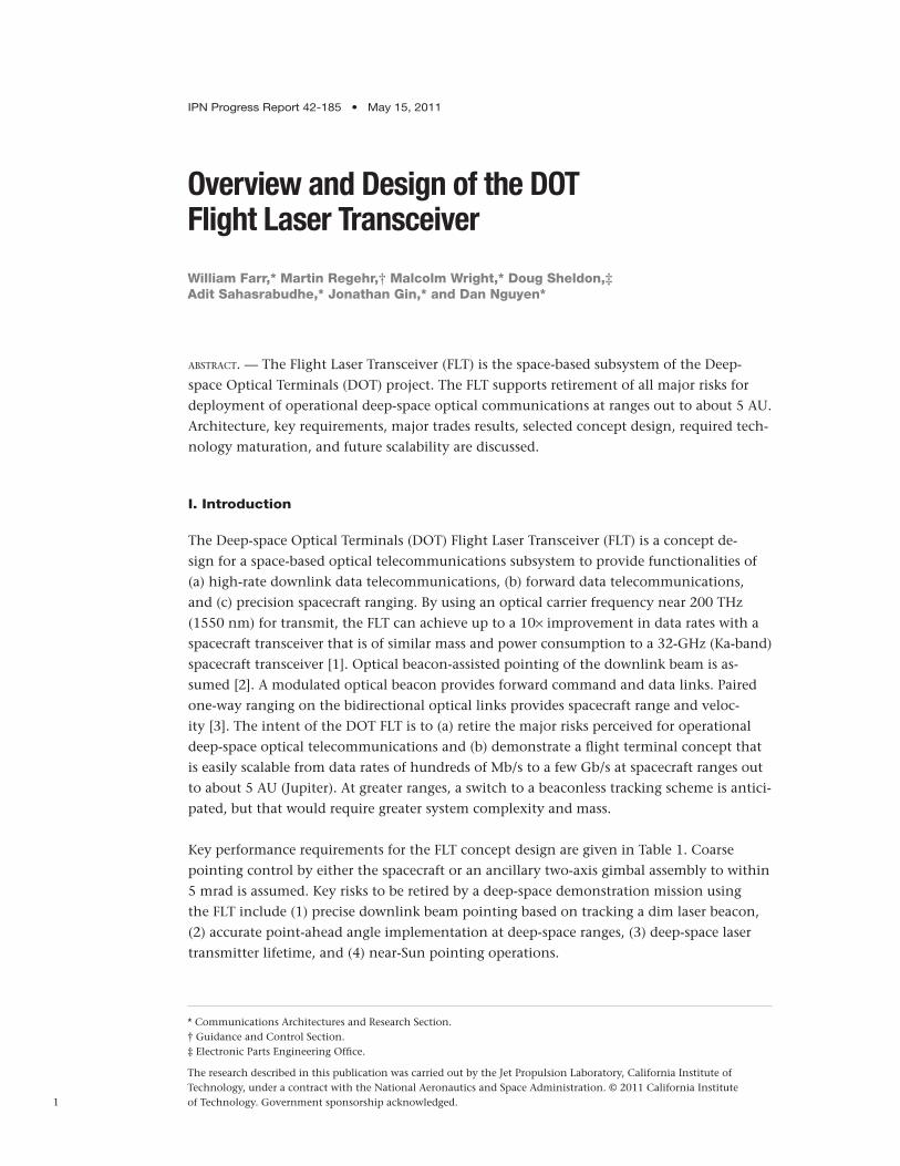
IPN Progress Report 42-185 • May 15, 2011
Overview and Design of the DOTFlight Laser Transceiver
William Farr,* Martin Regehr,† Malcolm Wright,* Doug Sheldon,‡ Adit Sahasrabudhe,* Jonathan Gin,* and Dan Nguyen*
* Communications Architectures and Research Section. † Guidance and Control Section. ‡ Electronic Parts Engineering Office.
The research described in this publication was carried out by the Jet Propulsion Laboratory, California Institute of Technology, under a contract with the National Aeronautics and Space Administration. © 2011 California Institute of Technology. Government sponsorship acknowledged.
abstract. — The Flight Laser Transceiver (FLT) is the space-based subsystem of the Deep-space Optical Terminals (DOT) project. The FLT supports retirement of all major risks for deployment of operational deep-space optical communications at ranges out to about 5 AU. Architecture, key requirements, major trades results, selected concept design, required tech-nology maturation, and future scalability are discussed.
I. Introduction
The Deep-space Optical Terminals (DOT) Flight Laser Transceiver (FLT) is a concept de-sign for a space-based optical telecommunications subsystem to provide functionalities of (a) high-rate downlink data telecommunications, (b) forward data telecommunications, and (c) precision spacecraft ranging. By using an optical carrier frequency near 200 THz (1550 nm) for transmit, the FLT can achieve up to a 10× improvement in data rates with a spacecraft transceiver that is of similar mass and power consumption to a 32-GHz (Ka-band) spacecraft transceiver [1]. Optical beacon-assisted pointing of the downlink beam is as-sumed [2]. A modulated optical beacon provides forward command and data links. Paired one-way ranging on the bidirectional optical links provides spacecraft range and veloc-ity [3]. The intent of the DOT FLT is to (a) retire the major risks perceived for operational deep-space optical telecommunications and (b) demonstrate a flight terminal concept that is easily scalable from data rates of hundreds of Mb/s to a few Gb/s at spacecraft ranges out to about 5 AU (Jupiter). At greater ranges, a switch to a beaconless tracking scheme is antici-pated, but that would require greater system complexity and mass.
Key performance requirements for the FLT concept design are given in Table 1. Coarse pointing control by either the spacecraft or an ancillary two-axis gimbal assembly to within 5 mrad is assumed. Key risks to be retired by a deep-space demonstration mission using the FLT include (1) precise downlink beam pointing based on tracking a dim laser beacon, (2) accurate point-ahead angle implementation at deep-space ranges, (3) deep-space laser transmitter lifetime, and (4) near-Sun pointing operations.
2
Although beacon-assisted downlink beam pointing has been well demonstrated in near-Earth orbital operations, much greater 1/R2 losses on an Earth-transmitted beacon laser require more challenging solutions than have been presently demonstrated or planned. The large transverse velocities between transmitter and receiver encountered at deep-space rang-es result in point-ahead angles of several tens of beamwidths, rather than the sub to few beamwidths of point-ahead angle encountered in near-Earth domains [4]. At present, the most efficient signaling scheme for an optical telecommunications link utilizes the serially concatenated pulse-position modulation (SCPPM) scheme that requires a laser transmitter peak power on the order of ~1 kW with an average power of a few watts, and that class of laser has not been deployed in space yet [5]. Finally, to achieve minimal spacecraft mass and power burdens requires Earth-receive apertures of 10 m or greater equivalent diameter, which can result in background noise greater than received signal power during daytime operations [6].
Although deep-space conditions can be somewhat emulated with a near-Earth demon-stration, full mission acceptance will only occur after a complete deep-space operational demonstration. Additionally, some conditions experienced in deep space never can occur in near-Earth orbit; for instance, simultaneous low Sun–probe–Earth and Sun–Earth–probe angles that result in simultaneous low signal-to-noise ratios for both the optical transmit and receive stations.
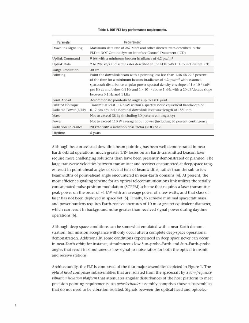
Architecturally, the FLT is composed of the four major assemblies depicted in Figure 1. The optical head comprises subassemblies that are isolated from the spacecraft by a low-frequency
vibration isolation platform that attenuates angular disturbances of the host platform to meet precision pointing requirements. An optoelectronics assembly comprises those subassemblies that do not need to be vibration isolated. Signals between the optical head and optoelec-
Table 1. DOT FLT key performance requirements.
Parameter Requirement
Downlink Signaling Maximum data rate of 267 Mb/s and other discrete rates described in the FLT-to-DOT Ground System Interface Control Document (ICD)
Uplink Command 9 b/s with a minimum beacon irradiance of 4.2 pw/m2
Uplink Data 2 to 292 kb/s at discrete rates described in the FLT-to-DOT Ground System ICD
Range Resolution 30 cmPointing Point the downlink beam with a pointing loss less than 1.46 dB 99.7 percent of the time for a minimum beacon irradiance of 4.2 pw/m2 with assumed spacecraft disturbance angular power spectral density envelope of 1 × 10⁻⁷ rad2
per Hz at and below 0.1 Hz and 1 × 10–15 above 1 kHz with a 20 dB/decade slope between 0.1 Hz and 1 kHz
Point Ahead Accommodate point-ahead angles up to ±400 µradEmitted Isotropic Transmit at least 114 dBW within a spectral noise equivalent bandwidth of Radiated Power (EIRP) 0.17 nm around a nominal downlink laser wavelength of 1550 nm
Mass Not to exceed 38 kg (including 30 percent contingency)
Power Not to exceed 110 W average input power (including 30 percent contingency)
Radiation Tolerance 20 krad with a radiation dose factor (RDF) of 2
Lifetime 5 years
3
tronics assemblies are carried by an umbilical cord that must not short-circuit the isolation provided by the low-frequency vibration isolation platform.
The optical head comprises the optical transmit and receive aperture(s), as well as the optics required to track the receive signal and relay it to an optical detector, and relay and point the transmit signal from the transmit laser. To minimize the size and dissipated power within the optical head, the transmit laser subassembly is located in the non-vibration-isolated optoelectronics assembly. This assembly also contains a processor subassembly to implement beacon tracking, uplink data demodulation and spacecraft interface, down-link data modulation and spacecraft interface, transmit beam point-ahead and pointing control, paired one-way ranging signal processing, and command and monitor interfaces to a host spacecraft processor. The low-frequency vibration isolation platform comprises subassemblies to reject the majority of spacecraft-induced angular disturbances, either passively or under active control by the optoelectronics processor. Additional rejection may be performed by beam-steering subassemblies within the optical head. The umbilical cord comprises highly compliant optical fiber and electrical wire connections for transmit and receive data, optical beam tracking and pointing control, and optical head power and thermal management. Ancillary subassemblies provide power conditioning and thermal management of the optical head and optoelectronics assemblies.
A. Pointing, Acquisition, and Tracking
Achieving adequate pointing performance is a major driver to the FLT concept design, due to the combination of dim beacon tracking and the mass and power limits specified in Table 1. The pointing loss requirement of that table equates to a derived submicroradian
Figure 1. FLT major assemblies reference architecture.
Sp
acec
raft
Ele
ctric
al B
us
Uplink
Downlink
Optical Fiber
Electrical Power
Data
Optical Head PowerCond.
ThermalMgmt.
AFT Electro-Optics
Assembly
Low-Frequency
Vibration Isolation
Platform
Optical
Transceiver
Assembly
Optoelectronics
Spacecraft
OpticalFiber
LVDS
1553
28 V
LaserTransmitterAssembly
ProcessorAssembly
PowerConditioning
Unit
ThermalManagement
UmbilicalCord
4
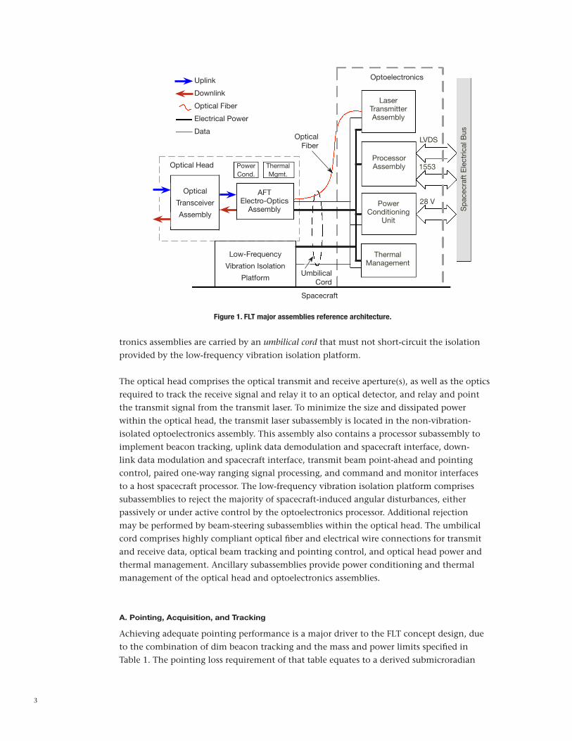
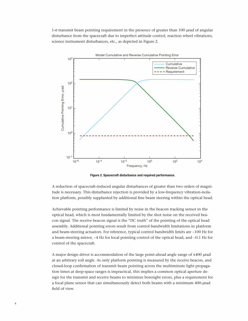
1-σ transmit beam pointing requirement in the presence of greater than 100 µrad of angular disturbance from the spacecraft due to imperfect attitude control, reaction wheel vibrations, science instrument disturbances, etc., as depicted in Figure 2.
Model Cumulative and Reverse Cumulative Pointing Error
CumulativeReverse CumulativeRequirement
10–6
103
102
101
100
10–1
10–4 10–2 100 102 104
Frequency, Hz
Cum
ulat
ive
Poi
ntin
g E
rror
, mra
d
Figure 2. Spacecraft disturbance and required performance.
A reduction of spacecraft-induced angular disturbances of greater than two orders of magni-tude is necessary. This disturbance rejection is provided by a low-frequency vibration-isola-tion platform, possibly supplanted by additional fine beam steering within the optical head.
Achievable pointing performance is limited by noise in the beacon tracking sensor in the optical head, which is most fundamentally limited by the shot noise on the received bea-con signal. The receive beacon signal is the “DC truth” of the pointing of the optical head assembly. Additional pointing errors result from control bandwidth limitations in platform and beam-steering actuators. For reference, typical control bandwidth limits are ~100 Hz for a beam-steering mirror, ~4 Hz for local pointing control of the optical head, and ~0.1 Hz for control of the spacecraft.
A major design driver is accommodation of the large point-ahead angle range of ±400 µrad at an arbitrary roll angle. As only platform pointing is measured by the receive beacon, and closed-loop confirmation of transmit beam pointing across the multiminute light propaga-tion times at deep-space ranges is impractical, this implies a common optical aperture de-sign for the transmit and receive beams to minimize boresight errors, plus a requirement for a focal plane sensor that can simultaneously detect both beams with a minimum 400-µrad field of view.
5
B. Downlink Communications
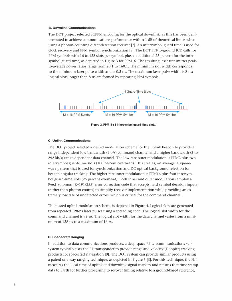
The DOT project selected SCPPM encoding for the optical downlink, as this has been dem-onstrated to achieve communications performance within 1 dB of theoretical limits when using a photon-counting direct-detection receiver [7]. An intersymbol guard time is used for clock recovery and PPM symbol synchronization [8]. The DOT FLT-to-ground ICD calls for PPM symbols with 16 to 128 slots per symbol, plus an additional 25 percent for the inter-symbol guard time, as depicted in Figure 3 for PPM16. The resulting laser transmitter peak-to-average power ratios range from 20:1 to 160:1. The minimum slot width corresponds to the minimum laser pulse width and is 0.5 ns. The maximum laser pulse width is 8 ns; logical slots longer than 8 ns are formed by repeating PPM symbols.
4 Guard-Time Slots
M = 16 PPM Symbol M = 16 PPM Symbol M = 16 PPM Symbol
Figure 3. PPM16+4 intersymbol guard-time slots.
C. Uplink Communications
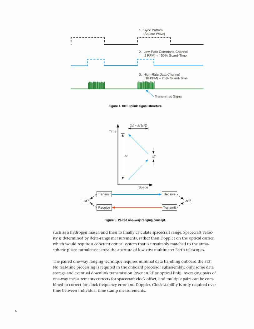
The DOT project selected a nested modulation scheme for the uplink beacon to provide a range-independent low-bandwidth (9 b/s) command channel and a higher bandwidth (2 to 292 kb/s) range-dependent data channel. The low-rate outer modulation is PPM2 plus two intersymbol guard-time slots (100 percent overhead). This creates, on average, a square-wave pattern that is used for synchronization and DC optical background rejection for beacon angular tracking. The higher rate inner modulation is PPM16 plus four intersym-bol guard-time slots (25 percent overhead). Both inner and outer modulations employ a Reed–Solomon (R=191/255) error-correction code that accepts hard-symbol decision inputs (rather than photon counts) to simplify receiver implementation while providing an ex-tremely low rate of undetected errors, which is critical for the command channel. The nested uplink modulation scheme is depicted in Figure 4. Logical slots are generated from repeated 128-ns laser pulses using a spreading code. The logical slot width for the command channel is 82 µs. The logical slot width for the data channel varies from a mini-mum of 128 ns to a maximum of 16 µs.
D. Spacecraft Ranging
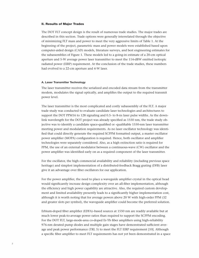
In addition to data communications products, a deep-space RF telecommunications sub-system typically uses the RF transponder to provide range and velocity (Doppler) tracking products for spacecraft navigation [9]. The DOT system can provide similar products using a paired one-way ranging technique, as depicted in Figure 5 [3]. For this technique, the FLT measures the local time of uplink and downlink signal markers and returns that time stamp data to Earth for further processing to recover timing relative to a ground-based reference,
6
Figure 4. DOT uplink signal structure.
Figure 5. Paired one-way ranging concept.
(∆t – ∆t′)c/2
Transmit
Transmit
Receive
Receive
∆t? ∆t′?
∆t ∆t′
Time
Space
1. Sync Pattern (Square Wave)
2. Low-Rate Command Channel (2 PPM) + 100% Guard-Time
3. High-Rate Data Channel (16 PPM) + 25% Guard-Time
Transmitted Signal
such as a hydrogen maser, and then to finally calculate spacecraft range. Spacecraft veloc-ity is determined by delta-range measurements, rather than Doppler on the optical carrier, which would require a coherent optical system that is unsuitably matched to the atmo-spheric phase turbulence across the aperture of low-cost multimeter Earth telescopes.
The paired one-way ranging technique requires minimal data handling onboard the FLT. No real-time processing is required in the onboard processor subassembly, only some data storage and eventual downlink transmission (over an RF or optical link). Averaging pairs of one-way measurements corrects for spacecraft clock offset, and multiple pairs can be com-bined to correct for clock frequency error and Doppler. Clock stability is only required over time between individual time stamp measurements.
7
II. Results of Major Trades
The DOT FLT concept design is the result of numerous trade studies. The major trades are described in this section. Trade options were generally interrelated through the objective of minimizing FLT mass and power to meet the very aggressive limits of Table 1. At the beginning of the project, parametric mass and power models were established based upon computer-aided design (CAD) models, literature surveys, and best engineering estimates for the subassemblies of Figure 1. These models led to a going-in estimate of a 20-cm optical aperture and 5-W average power laser transmitter to meet the 114-dBW emitted isotropic radiated power (EIRP) requirement. At the conclusion of the trade studies, these numbers had evolved to a 22-cm aperture and 4-W laser.
A. Laser Transmitter Technology
The laser transmitter receives the serialized and encoded data stream from the transmitter modem, modulates the signal optically, and amplifies the output to the required transmit power level.
The laser transmitter is the most complicated and costly subassembly of the FLT. A major trade study was conducted to evaluate candidate laser technologies and architectures to support the DOT PPM16 to 128 signaling and 0.5- to 8-ns laser pulse widths. As the down-link wavelength for the DOT project was already specified as 1550 nm, the trade study ob-jective was to identify a candidate space-qualified or -qualifiable 1550-nm laser transmitter meeting power and modulation requirements. As no laser oscillator technology was identi-fied that could directly generate the required SCPPM formatted output, a master oscillator power amplifier (MOPA) configuration is required. Hence, both oscillator and amplifier technologies were separately considered. Also, as a high extinction ratio is required for PPM, the use of an external modulator between a continuous-wave (CW) oscillator and the power amplifier was identified early on as a required component of the laser transmitter.
For the oscillator, the high commercial availability and reliability (including previous space heritage) and simplest implementation of a distributed-feedback Bragg grating (DFB) laser give it an advantage over fiber oscillators for our application. For the power amplifier, the need to place a waveguide amplifier crystal in the optical head would significantly increase design complexity over an all-fiber implementation, although the efficiency and high power capability are attractive. Also, the required custom develop-ment and limited availability presently leads to a significantly higher implementation cost, although it is worth noting that for average powers above 20 W with high-order PPM (32 and greater slots per symbol), the waveguide amplifier could become the preferred solution.
Erbium-doped fiber amplifier (EDFA)–based sources at 1550 nm are readily available but at much lower peak-to-average power ratios than required to support the SCPPM encoding. For the DOT FLT, large-mode-area co-doped Er-Yb fiber amplifiers using high-reliability 976-nm derated pump diodes and multiple gain stages have demonstrated sufficient aver-age and peak power performance (TRL 5) to meet the FLT EIRP requirement [10]. Although a specific fiber amplifier to meet FLT requirements has not yet been demonstrated in a space
8
environment (TRL 6 or above), coherent (peak-to-average power of one) and on-off-keyed (peak-to-average power of two) fiber-based amplifiers have been space qualified (TRL 6–9).
B. Uplink Detector Technology
According to the DOT ground-to-FLT ICD, the uplink beacon wavelength is specified at 1030 nm, which can be generated at kilowatt average power levels with relative ease and allows the use of a silicon absorber. Many candidate detector technologies for the FLT were evaluated for acquisition, tracking, and data detector sensors with the objective to identify candidate space-qualified/-qualifiable detectors to meet uplink acquisition, tracking, and data-detection requirements.
At 1030 nm, germanium, InGaAs, and InGaAsP are also viable semiconductor optical ab-sorber materials. An additional requirement for the FLT uplink beacon tracking is the ability to simultaneously track the downlink beam to verify the point-ahead angle. This would seem at first glance to disqualify the use of silicon (1.1 µm cutoff) or InGaAsP (1.3 µm cutoff) absorbers, but actually this is not the case for the FLT, as centroiding on a silicon detector of a 1.5-µm laser with submilliwatt average power has been demonstrated via a two-photon absorption process [11]. Furthermore, use of the non–1550-nm sensitive detec-tor then becomes advantageous due to the inherent transmit–receive isolation afforded by the absorber physics.
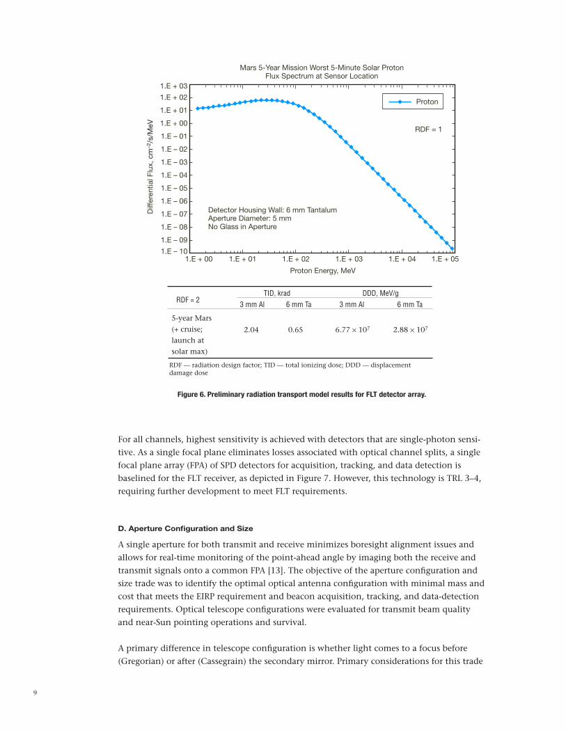
The space radiation environment is a significant design driver, since a five-year mission lifetime requirement must be met. Preliminary radiation transport models were generated for radiation testing of single-photon detectors (SPDs) for the FLT. The JPL91 statistical solar proton model was used to estimate mission proton fluences from flares at 1 AU scaled to distances >1 AU using the inverse square law. The results of these preliminary models are shown in Figure 6.
SPD technologies are the most sensitive and have been selected to demonstrate on the DOT FLT to achieve highest system efficiency. Of the SPD technologies, superconducting technologies are considered unsuitable for the FLT due to the mass and power burden of as-sociated cryogenic systems, and vacuum tube technologies are unsuitable for the FLT due to limited lifetime of present photocathodes. The primary disadvantage of the semiconductor SPD technologies is their present low TRL for high-efficiency 1030 nm detection, and they are the most susceptible to radiation damage [12].
C. Optical Receiver Channels Configuration
The received Earth laser beacon serves three functions in the FLT: initial acquisition (coarse pointing confirmation), tracking (beam stabilization), and uplink data. These functions could be implemented with as few as one and as many as three detector channels.
The objective of the optical receiver channels configuration trade was to identify the opti-mal configuration of receive optical channels to maximize uplink photon efficiencies with minimum volume, mass, and power.
9
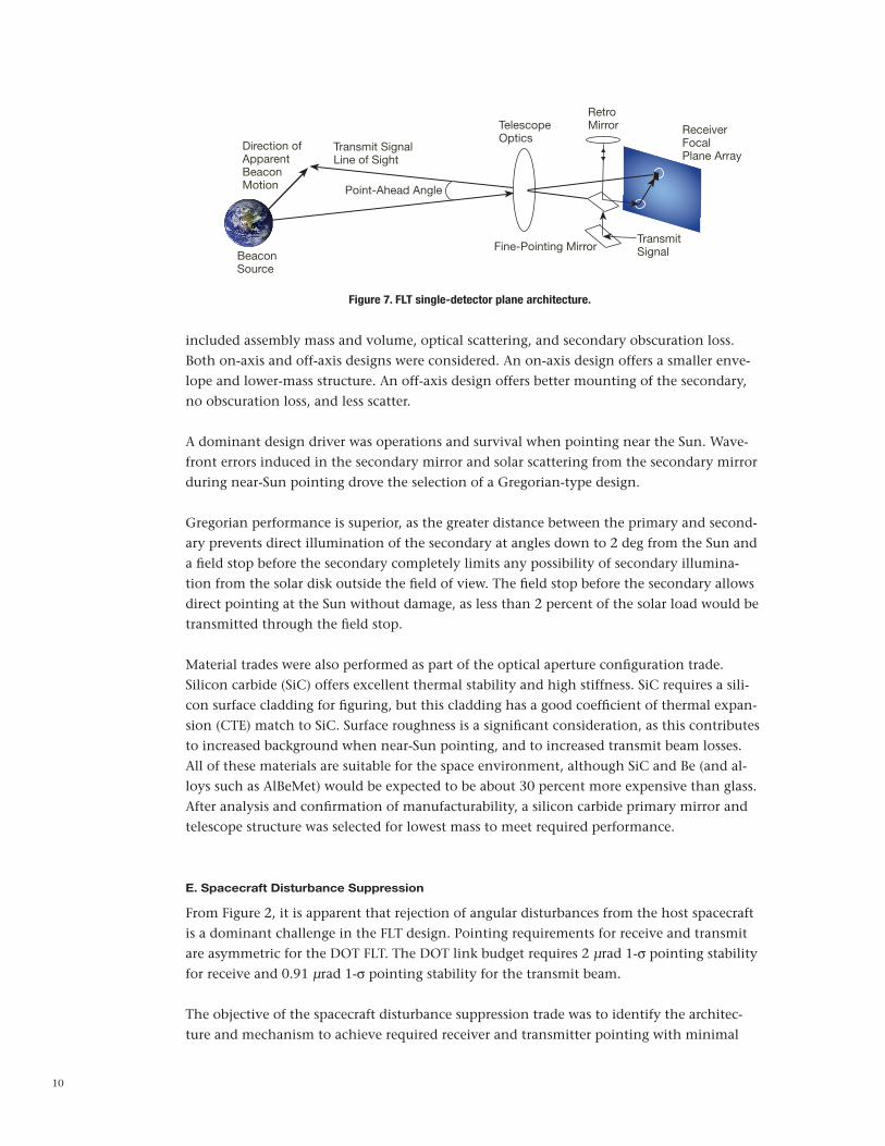
For all channels, highest sensitivity is achieved with detectors that are single-photon sensi-tive. As a single focal plane eliminates losses associated with optical channel splits, a single focal plane array (FPA) of SPD detectors for acquisition, tracking, and data detection is baselined for the FLT receiver, as depicted in Figure 7. However, this technology is TRL 3–4, requiring further development to meet FLT requirements.
D. Aperture Configuration and Size
A single aperture for both transmit and receive minimizes boresight alignment issues and allows for real-time monitoring of the point-ahead angle by imaging both the receive and transmit signals onto a common FPA [13]. The objective of the aperture configuration and size trade was to identify the optimal optical antenna configuration with minimal mass and cost that meets the EIRP requirement and beacon acquisition, tracking, and data-detection requirements. Optical telescope configurations were evaluated for transmit beam quality and near-Sun pointing operations and survival.
A primary difference in telescope configuration is whether light comes to a focus before (Gregorian) or after (Cassegrain) the secondary mirror. Primary considerations for this trade
6 mm Ta
2.88 × 10⁷
6 mm Ta
TID, krad
3 mm Al 3 mm Al
5-year Mars (+ cruise; launch at solar max)
2.04 0.65 6.77 × 10⁷
RDF = 2DDD, MeV/g
RDF — radiation design factor; TID — total ionizing dose; DDD — displacement damage dose
Mars 5-Year Mission Worst 5-Minute Solar ProtonFlux Spectrum at Sensor Location
Proton
RDF = 1
1.E + 03
1.E + 00 1.E + 01 1.E + 02 1.E + 03 1.E + 04 1.E + 05
1.E + 02
1.E + 01
1.E + 00
1.E – 01
1.E – 02
1.E – 03
1.E – 04
1.E – 05
1.E – 06
1.E – 07
1.E – 08
1.E – 09
1.E – 10
Proton Energy, MeV
Diff
eren
tial F
lux,
cm
–2/s
/MeV
Detector Housing Wall: 6 mm TantalumAperture Diameter: 5 mmNo Glass in Aperture
Figure 6. Preliminary radiation transport model results for FLT detector array.
10
included assembly mass and volume, optical scattering, and secondary obscuration loss. Both on-axis and off-axis designs were considered. An on-axis design offers a smaller enve-lope and lower-mass structure. An off-axis design offers better mounting of the secondary, no obscuration loss, and less scatter.
A dominant design driver was operations and survival when pointing near the Sun. Wave-front errors induced in the secondary mirror and solar scattering from the secondary mirror during near-Sun pointing drove the selection of a Gregorian-type design.
Gregorian performance is superior, as the greater distance between the primary and second-ary prevents direct illumination of the secondary at angles down to 2 deg from the Sun and a field stop before the secondary completely limits any possibility of secondary illumina-tion from the solar disk outside the field of view. The field stop before the secondary allows direct pointing at the Sun without damage, as less than 2 percent of the solar load would be transmitted through the field stop.
Material trades were also performed as part of the optical aperture configuration trade.Silicon carbide (SiC) offers excellent thermal stability and high stiffness. SiC requires a sili-con surface cladding for figuring, but this cladding has a good coefficient of thermal expan-sion (CTE) match to SiC. Surface roughness is a significant consideration, as this contributes to increased background when near-Sun pointing, and to increased transmit beam losses. All of these materials are suitable for the space environment, although SiC and Be (and al-loys such as AlBeMet) would be expected to be about 30 percent more expensive than glass. After analysis and confirmation of manufacturability, a silicon carbide primary mirror and telescope structure was selected for lowest mass to meet required performance.
E. Spacecraft Disturbance Suppression
From Figure 2, it is apparent that rejection of angular disturbances from the host spacecraft is a dominant challenge in the FLT design. Pointing requirements for receive and transmit are asymmetric for the DOT FLT. The DOT link budget requires 2 µrad 1-σ pointing stability for receive and 0.91 µrad 1-σ pointing stability for the transmit beam.
The objective of the spacecraft disturbance suppression trade was to identify the architec-ture and mechanism to achieve required receiver and transmitter pointing with minimal
Figure 7. FLT single-detector plane architecture.
Direction ofApparentBeaconMotion
Transmit SignalLine of Sight
Point-Ahead Angle
BeaconSource
TelescopeOptics
RetroMirror Receiver
FocalPlane Array
TransmitSignalFine-Pointing Mirror

11
mass and power burden. This trade evaluated active, passive, and hybrid schemes to miti-gate the adverse affects of spacecraft disturbances on beam pointing.
From the architecture reference in Figure 1, we refer to an isolation subsystem that attenu-ates the coupling of disturbances from the host spacecraft to the optical head assembly, and uses active cancellation to further reduce the disturbances that do reach the optical head. It is important to distinguish between “following” and “suppression” for platform operation. The platform must follow the spacecraft at low frequencies (<10 mHz), in X, Y, Z, and roll to prevent collisions between the platform and stops on the spacecraft, but it must suppress (not follow) spacecraft motion in pitch and yaw to allow the platform to be quieter than the spacecraft in these degrees of freedom.
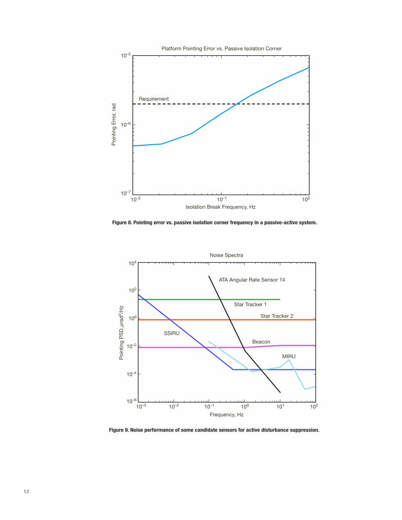
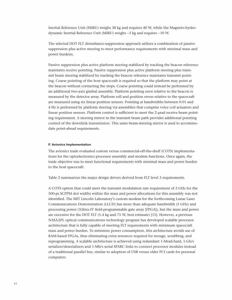
For passive suppression, a mechanically soft connection (or ideally no connection) acts as a mechanical low-pass filter to attenuate transmission of vibrations. Passive suppression to reduce the mechanical coupling between the host spacecraft and the FLT optical head as-sembly can utilize elastomeric or spring mounts, for instance. The softer the mount, i.e., the lower the break frequency, the greater the passive isolation achieved. Passive isolation alone would require a very low break frequency to meet the pointing requirements. If passive iso-lation is combined with active cancellation, the passive break frequency may be significant-ly higher. Figure 8 shows the pointing error as a function of break (or “corner”) frequency, assuming an active cancellation system with a 4-Hz unity gain frequency; the requirement is met for a break frequency of 100 mHz or less.
An active feedback or feedforward suppression system exerts forces and torques on the plat-form or beam-steering mirror(s) to counteract disturbances produced by the host spacecraft. Active suppression requires sensors to measure the induced spacecraft disturbances plus a controller and actuator assembly to apply corrections to cancel pointing errors. The actua-tors can either apply forces to the entire optical assembly mounting platform to counteract disturbances from the spacecraft, or be steering mirrors on the platform.
The assumed ±5 mrad range of spacecraft attitudes makes a steering mirror–only approach impractical because the selected Gregorian design has large field curvature for fields of view greater than approximately 1 mrad. The attitude range also dictates required clearance in voice coils and sensors, and can drive magnet sizes and power consumption. The large at-titude range further makes active softening of stiffer (>1–2 Hz) springs difficult due to the large force required to hold the platform in position against the spring. For instance, 2.6 N of force would be required to hold a 5-mrad angle against a 5-Hz spring, assuming a 0.1-m lever arm to each of two actuators and a 0.1-kg m2 moment of inertia.
Sensor noise limits the bandwidth at which an active system can operate: if the bandwidth is too high, sensor noise will degrade pointing performance. Sensors for active suppression include local inertial reference sensors, Earthlight, or the laser beacon transmitted from Earth. The laser beacon provides a “DC” reference pointing source. Earthlight has signifi-cant challenges with uncertainty due to albedo variations from variable cloud cover [14]. Local sensors generally suffer either from high mass and power requirements, or offer poor low-frequency noise performance, as depicted in Figure 9. As examples, the Scalable Space
12
Figure 8. Pointing error vs. passive isolation corner frequency in a passive-active system.
Platform Pointing Error vs. Passive Isolation Corner
Requirement
Isolation Break Frequency, Hz
Poi
ntin
g E
rror
, rad
10–5
10–6
10–7
10–2 10–1 100
10–3 10–2 10–1 100 101 102
104
102
100
10–2
10–4
10–6
Noise Spectra
Star Tracker 1
Star Tracker 2
Beacon
SSIRU
MIRU
Frequency, Hz
Poi
ntin
g P
SD
, mra
d2 /
Hz
ATA Angular Rate Sensor 14
Figure 9. Noise performance of some candidate sensors for active disturbance suppression.
13
Inertial Reference Unit (SSIRU) weighs 38 kg and requires 40 W, while the Magneto-hydro-dynamic Inertial Reference Unit (MIRU) weighs ~3 kg and requires ~10 W.
The selected DOT FLT disturbance-suppression approach utilizes a combination of passive suppression plus active steering to meet performance requirements with minimal mass and power burdens.
Passive suppression plus active platform steering stabilized by tracking the beacon reference maintains receive pointing. Passive suppression plus active platform steering plus trans-mit beam steering stabilized by tracking the beacon reference maintains transmit point-ing. Coarse pointing of the host spacecraft is required so that the platform may point at the beacon without contacting the stops. Coarse pointing could instead be performed by an additional two-axis gimbal assembly. Platform pointing error relative to the beacon is measured by the detector array. Platform roll and position errors relative to the spacecraft are measured using six linear position sensors. Pointing at bandwidths between 0.01 and 4 Hz is performed by platform steering via assemblies that comprise voice coil actuators and linear position sensors. Platform control is sufficient to meet the 2-µrad receive beam point-ing requirement. A steering mirror in the transmit beam path provides additional pointing control of the downlink transmission. This same beam-steering mirror is used to accommo-date point-ahead requirements.
F. Avionics Implementation
The avionics trade evaluated custom versus commercial-off-the-shelf (COTS) implementa-tions for the optoelectronics processor assembly and modem functions. Once again, the trade objective was to meet functional requirements with minimal mass and power burden to the host spacecraft.
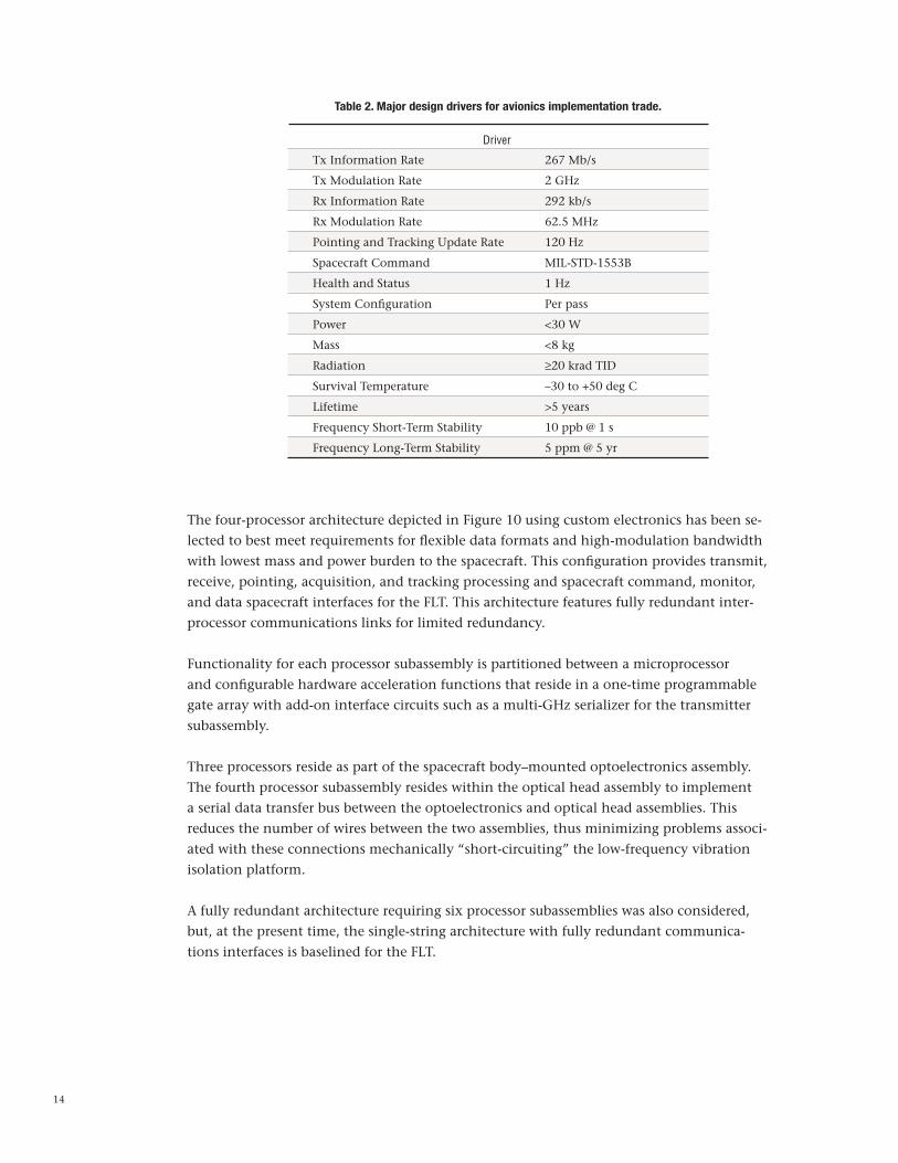
Table 2 summarizes the major design drivers derived from FLT level 3 requirements. A COTS option that could meet the transmit modulation rate requirement of 2 GHz for the 500-ps SCPPM slot widths within the mass and power allocations for this assembly was not identified. The MIT Lincoln Laboratory’s custom modem for the forthcoming Lunar Laser Communications Demonstration (LLCD) has more than adequate bandwidth (5 GHz) and processing power (Xilinx-IV field-programmable gate array [FPGA]), but the mass and power are excessive for the DOT FLT (5.4 kg and 75 W, best estimate) [15]. However, a previous NASA/JPL optical communications technology program has developed scalable processor architecture that is fully capable of meeting FLT requirements with minimum spacecraft mass and power burden. To minimize power consumption, this architecture avoids use of RAM-based FPGAs, thus eliminating extra resources required for storage, scrubbing, and reprogramming. A scalable architecture is achieved using redundant 1-Mrad-hard, 1-Gb/s serializer/deserializers and 1-Mb/s serial SPARC links to connect processor modules instead of a traditional parallel bus, similar to adoption of USB versus older PCI cards for personal computers.
14
Tx Information Rate 267 Mb/s
Tx Modulation Rate 2 GHz
Rx Information Rate 292 kb/s
Rx Modulation Rate 62.5 MHz
Pointing and Tracking Update Rate 120 Hz
Spacecraft Command MIL-STD-1553B
Health and Status 1 Hz
System Configuration Per pass
Power <30 W
Mass <8 kg
Radiation ≥20 krad TID
Survival Temperature –30 to +50 deg C
Lifetime >5 years
Frequency Short-Term Stability 10 ppb @ 1 s
Frequency Long-Term Stability 5 ppm @ 5 yr
Table 2. Major design drivers for avionics implementation trade.
Driver
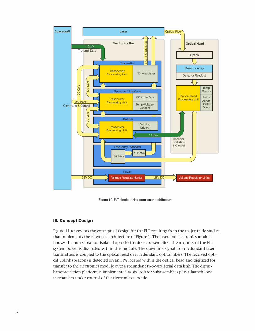
The four-processor architecture depicted in Figure 10 using custom electronics has been se-lected to best meet requirements for flexible data formats and high-modulation bandwidth with lowest mass and power burden to the spacecraft. This configuration provides transmit, receive, pointing, acquisition, and tracking processing and spacecraft command, monitor, and data spacecraft interfaces for the FLT. This architecture features fully redundant inter-processor communications links for limited redundancy.
Functionality for each processor subassembly is partitioned between a microprocessor and configurable hardware acceleration functions that reside in a one-time programmable gate array with add-on interface circuits such as a multi-GHz serializer for the transmitter subassembly.
Three processors reside as part of the spacecraft body–mounted optoelectronics assembly. The fourth processor subassembly resides within the optical head assembly to implement a serial data transfer bus between the optoelectronics and optical head assemblies. This reduces the number of wires between the two assemblies, thus minimizing problems associ-ated with these connections mechanically “short-circuiting” the low-frequency vibration isolation platform.
A fully redundant architecture requiring six processor subassemblies was also considered, but, at the present time, the single-string architecture with fully redundant communica-tions interfaces is baselined for the FLT.
15
Figure 10. FLT single-string processor architecture.
Spacecraft
Electronics Box Optical Head
Detector Readout
Optical HeadProcessing Unit
Temp.Sensor
Point-AheadControlDriver
Transmit Data
Transmitter
TransceiverProcessing Unit
Command & Control
Spacecraft Interface
1553 Interface
Temp/VoltageSensors
Receiver
Frequency Standard
Power
ReceiverStatistics& Control
2 G
Hz
Mod
ulat
ion
Optical Fiber
100
Kb
/s
100
Kb
/s10
0 K
b/s
28V DC 28V DC
1 Gb/s
1 Gb/s
125 MHzx16 PLL
Voltage Regulator Units Voltage Regulator Units
Optics
Detector ArrayTransceiver
Processing Unit TX Modulator
Laser
PointingDriversTransceiver
Processing Unit
500 Kb/s
III. Concept Design
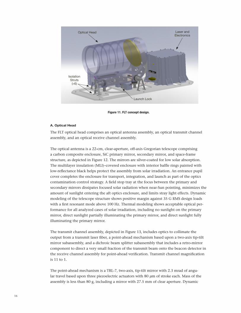
Figure 11 represents the conceptual design for the FLT resulting from the major trade studies that implements the reference architecture of Figure 1. The laser and electronics module houses the non-vibration-isolated optoelectronics subassemblies. The majority of the FLT system power is dissipated within this module. The downlink signal from redundant laser transmitters is coupled to the optical head over redundant optical fibers. The received opti-cal uplink (beacon) is detected on an FPA located within the optical head and digitized for transfer to the electronics module over a redundant two-wire serial data link. The distur-bance-rejection platform is implemented as six isolator subassemblies plus a launch lock mechanism under control of the electronics module.
16
A. Optical Head
The FLT optical head comprises an optical antenna assembly, an optical transmit channel assembly, and an optical receive channel assembly.
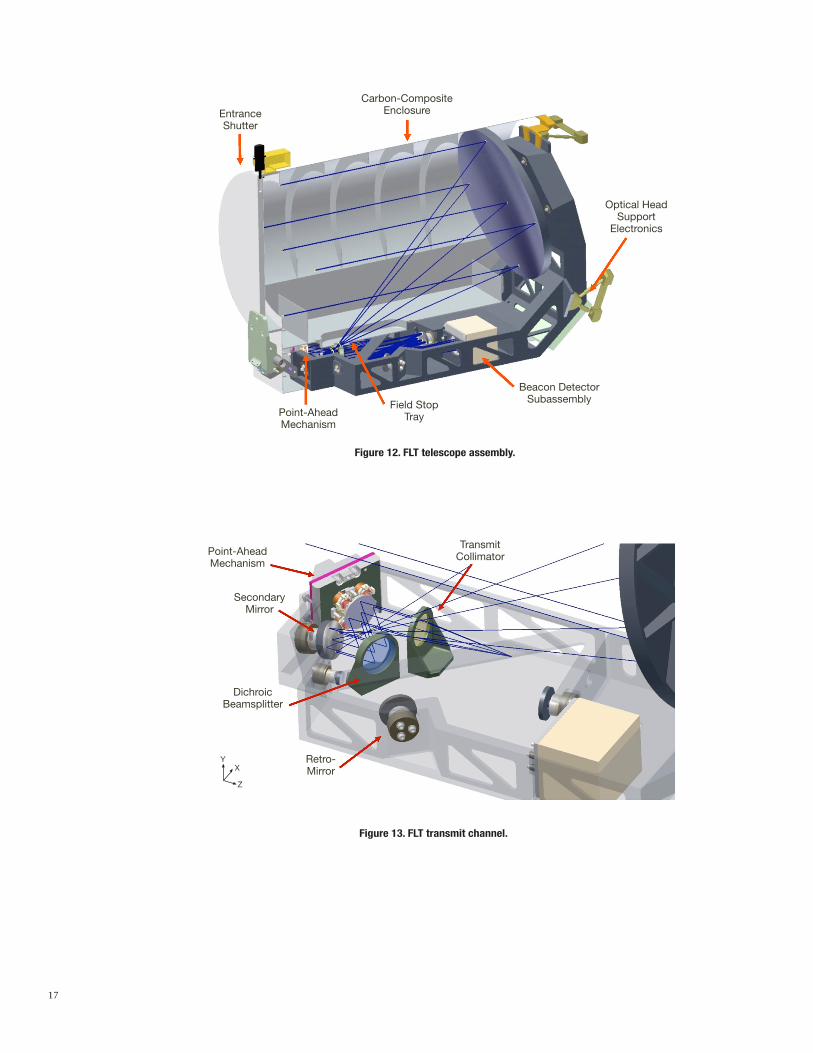
The optical antenna is a 22-cm, clear-aperture, off-axis Gregorian telescope comprising a carbon composite enclosure, SiC primary mirror, secondary mirror, and space-frame structure, as depicted in Figure 12. The mirrors are silver-coated for low solar absorption. The multilayer insulation (MLI)–covered enclosure with interior baffle rings painted with low-reflectance black helps protect the assembly from solar irradiation. An entrance pupil cover completes the enclosure for transport, integration, and launch as part of the optics contamination control strategy. A field stop tray at the focus between the primary and secondary mirrors dissipates focused solar radiation when near-Sun pointing, minimizes the amount of sunlight entering the aft optics enclosure, and limits stray light effects. Dynamic modeling of the telescope structure shows positive margin against 35 G RMS design loads with a first resonant mode above 100 Hz. Thermal modeling shows acceptable optical per-formance for all analyzed cases of solar irradiation, including no sunlight on the primary mirror, direct sunlight partially illuminating the primary mirror, and direct sunlight fully illuminating the primary mirror.
The transmit channel assembly, depicted in Figure 13, includes optics to collimate the output from a transmit laser fiber, a point-ahead mechanism based upon a two-axis tip-tilt mirror subassembly, and a dichroic beam splitter subassembly that includes a retro-mirror component to direct a very small fraction of the transmit beam onto the beacon detector in the receive channel assembly for point-ahead verification. Transmit channel magnification is 11 to 1.
The point-ahead mechanism is a TRL-7, two-axis, tip-tilt mirror with 2.3 mrad of angu-lar travel based upon three piezoelectric actuators with 80 µm of stroke each. Mass of the assembly is less than 80 g, including a mirror with 27.5 mm of clear aperture. Dynamic
Optical Head Laser andElectronics
IsolationStruts(×6)
Launch Lock
Figure 11. FLT concept design.
17
EntranceShutter
Carbon-CompositeEnclosure
Optical HeadSupport
Electronics
Beacon DetectorSubassemblyField Stop
TrayPoint-AheadMechanism
Figure 12. FLT telescope assembly.
Point-AheadMechanism
SecondaryMirror
DichroicBeamsplitter
Retro- Mirror
TransmitCollimator
YX
Z
Figure 13. FLT transmit channel.

18
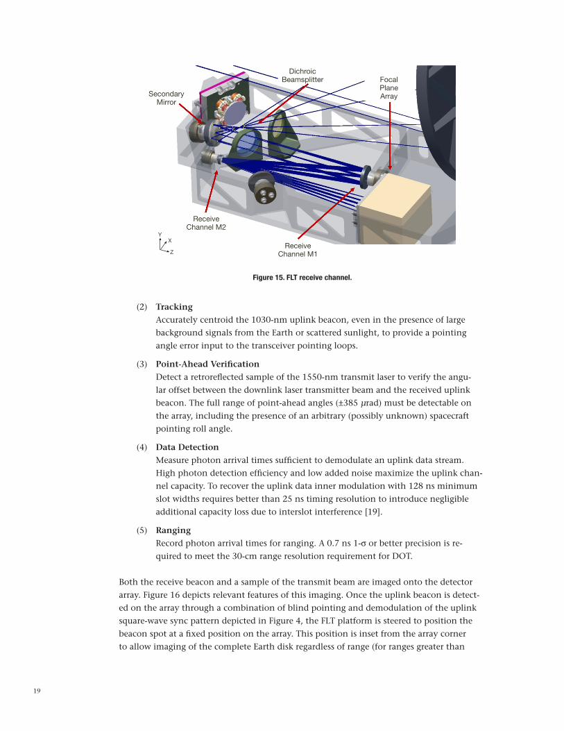
The FLT receive channel assembly depicted in Figure 15 is an off-axis Cassegrain telescope that maps a 1024-mrad field of view onto a 128 × 128 pixel focal plane detector array.
The baseline detector array is a resonant cavity, enhanced silicon absorber, Geiger mode photon-counting array [16]. The DOT uplink design control table assumes a 22 percent single-photon detection efficiency at the 1030-nm uplink wavelength and 1 kHz/pixel dark rate [17]. An alternate detector technology under consideration is a negative avalanche feedback photon-counting array using an InGaAsP absorber with a cutoff wavelength be-tween 1200 nm and 1300 nm [18]. Both technologies are presently TRL 3–4.
The uplink detector array converts absorbed photons into an electronic response measur-ing the time and angle of arrival. The timing information is used to demodulate the beacon signal and the spatial information is used to control receive and transmit beam pointing. The uplink detector array supports five major functions:
(1) Acquisition Detect the presence of the uplink beacon in space and time. The detector field of
regard should match the telescope (optical antenna) field of view. If necessary, the FLT platform is scanned to acquire the beacon.
analysis of the mechanism depicted in Figure 14 calculated both tip and tilt first resonant modes above 2 kHz, and verified that component stress limits were not exceeded for launch loads as high at 120 G RMS. A launch lock will not be required on this mechanism. To date, greater than 10 billion cycles of full actuator stroke at 600 Hz have been performed without degradation. The use of three actuators offers limited redundancy with reduced point-ahead capability with one failed actuator.
Figure 14. Two-axis, piezoelectric, tip-tilt point-ahead mechanism.
19
(2) Tracking Accurately centroid the 1030-nm uplink beacon, even in the presence of large
background signals from the Earth or scattered sunlight, to provide a pointing angle error input to the transceiver pointing loops.
(3) Point-Ahead Verification Detect a retroreflected sample of the 1550-nm transmit laser to verify the angu-
lar offset between the downlink laser transmitter beam and the received uplink beacon. The full range of point-ahead angles (±385 µrad) must be detectable on the array, including the presence of an arbitrary (possibly unknown) spacecraft pointing roll angle.
(4) Data Detection Measure photon arrival times sufficient to demodulate an uplink data stream.
High photon detection efficiency and low added noise maximize the uplink chan-nel capacity. To recover the uplink data inner modulation with 128 ns minimum slot widths requires better than 25 ns timing resolution to introduce negligible additional capacity loss due to interslot interference [19].
(5) Ranging Record photon arrival times for ranging. A 0.7 ns 1-σ or better precision is re-
quired to meet the 30-cm range resolution requirement for DOT.
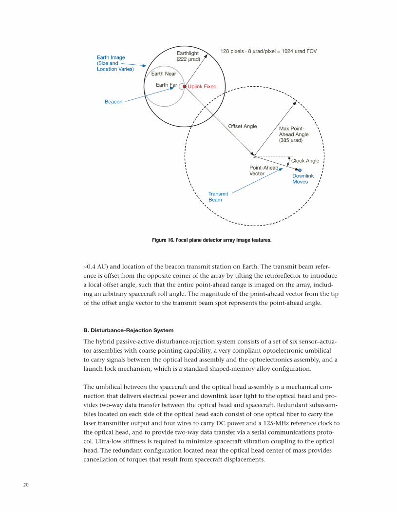
Both the receive beacon and a sample of the transmit beam are imaged onto the detector array. Figure 16 depicts relevant features of this imaging. Once the uplink beacon is detect-ed on the array through a combination of blind pointing and demodulation of the uplink square-wave sync pattern depicted in Figure 4, the FLT platform is steered to position the beacon spot at a fixed position on the array. This position is inset from the array corner to allow imaging of the complete Earth disk regardless of range (for ranges greater than
Figure 15. FLT receive channel.
SecondaryMirror
DichroicBeamsplitter
YX
Z
FocalPlaneArray
ReceiveChannel M2
ReceiveChannel M1
20
Figure 16. Focal plane detector array image features.
Earth Image(Size andLocation Varies)
Beacon
Earthlight(222 mrad)
Earth Near
Earth Far Uplink Fixed
Offset Angle
TransmitBeam
128 pixels · 8 mrad/pixel = 1024 mrad FOV
Max Point-Ahead Angle(385 mrad)
Clock AnglePoint-AheadVector Downlink
Moves
~0.4 AU) and location of the beacon transmit station on Earth. The transmit beam refer-ence is offset from the opposite corner of the array by tilting the retroreflector to introduce a local offset angle, such that the entire point-ahead range is imaged on the array, includ-ing an arbitrary spacecraft roll angle. The magnitude of the point-ahead vector from the tip of the offset angle vector to the transmit beam spot represents the point-ahead angle.
B. Disturbance-Rejection System
The hybrid passive-active disturbance-rejection system consists of a set of six sensor–actua-tor assemblies with coarse pointing capability, a very compliant optoelectronic umbilical to carry signals between the optical head assembly and the optoelectronics assembly, and a launch lock mechanism, which is a standard shaped-memory alloy configuration.
The umbilical between the spacecraft and the optical head assembly is a mechanical con-nection that delivers electrical power and downlink laser light to the optical head and pro-vides two-way data transfer between the optical head and spacecraft. Redundant subassem-blies located on each side of the optical head each consist of one optical fiber to carry the laser transmitter output and four wires to carry DC power and a 125-MHz reference clock to the optical head, and to provide two-way data transfer via a serial communications proto-col. Ultra-low stiffness is required to minimize spacecraft vibration coupling to the optical head. The redundant configuration located near the optical head center of mass provides cancellation of torques that result from spacecraft displacements.
21
The unjacketed optical fiber and wires are freely suspended between two clamps designed to minimize stress at the termination contact points. A housing tray that provides handling and launch protection for the optical fiber and wires is fabricated in two parts that are me-chanically decoupled to avoid contact and mechanical short-circuiting of the disturbance-isolation system.
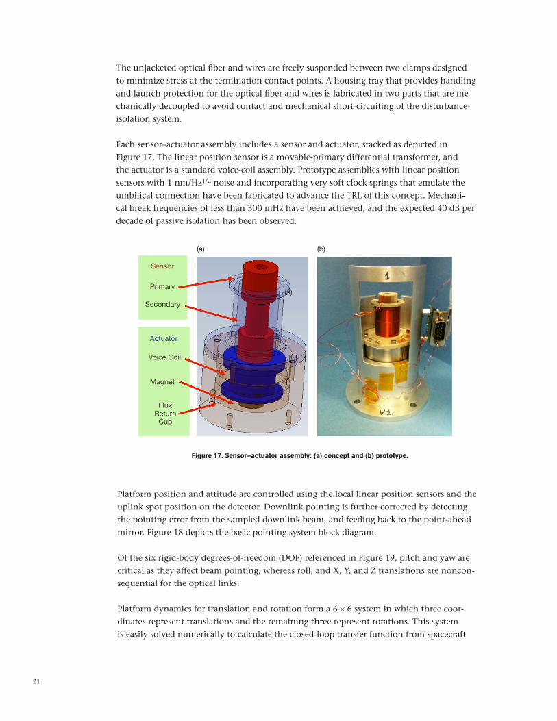
Each sensor–actuator assembly includes a sensor and actuator, stacked as depicted in Figure 17. The linear position sensor is a movable-primary differential transformer, and the actuator is a standard voice-coil assembly. Prototype assemblies with linear position sensors with 1 nm/Hz1/2 noise and incorporating very soft clock springs that emulate the umbilical connection have been fabricated to advance the TRL of this concept. Mechani-cal break frequencies of less than 300 mHz have been achieved, and the expected 40 dB per decade of passive isolation has been observed.
Figure 17. Sensor–actuator assembly: (a) concept and (b) prototype.
Sensor
Primary
Secondary
Actuator
Voice Coil
Magnet
FluxReturn
Cup
(a)
(a)
(b)
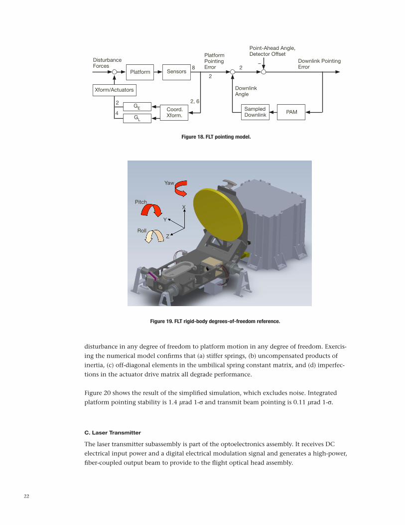
Platform position and attitude are controlled using the local linear position sensors and the uplink spot position on the detector. Downlink pointing is further corrected by detecting the pointing error from the sampled downlink beam, and feeding back to the point-ahead mirror. Figure 18 depicts the basic pointing system block diagram.
Of the six rigid-body degrees-of-freedom (DOF) referenced in Figure 19, pitch and yaw are critical as they affect beam pointing, whereas roll, and X, Y, and Z translations are noncon-sequential for the optical links.
Platform dynamics for translation and rotation form a 6 × 6 system in which three coor-dinates represent translations and the remaining three represent rotations. This system is easily solved numerically to calculate the closed-loop transfer function from spacecraft
22
Figure 18. FLT pointing model.
DisturbanceForces
PlatformPointingError
Point-Ahead Angle,Detector Offset
Downlink PointingError
DownlinkAngle
8
2
2
2
2, 6
Platform Sensors
SampledDownlink PAM
Xform/Actuators
4GE
GL
Coord.Xform.
–
Figure 19. FLT rigid-body degrees-of-freedom reference.
Yaw
Pitch
Roll
X
Y
Z
disturbance in any degree of freedom to platform motion in any degree of freedom. Exercis-ing the numerical model confirms that (a) stiffer springs, (b) uncompensated products of inertia, (c) off-diagonal elements in the umbilical spring constant matrix, and (d) imperfec-tions in the actuator drive matrix all degrade performance.
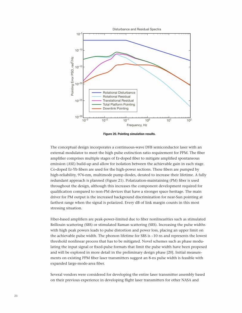
Figure 20 shows the result of the simplified simulation, which excludes noise. Integrated platform pointing stability is 1.4 µrad 1-σ and transmit beam pointing is 0.11 µrad 1-σ.
C. Laser Transmitter
The laser transmitter subassembly is part of the optoelectronics assembly. It receives DC electrical input power and a digital electrical modulation signal and generates a high-power, fiber-coupled output beam to provide to the flight optical head assembly.
23
Figure 20. Pointing simulation results.
10–3 10–2 10–1 100 101 102
10–5
10–10
10–15
10–20
10–25
10–30
Disturbance and Residual Spectra
Frequency, Hz
Poi
ntin
g E
rror
PS
D, r
ad2 /
Hz
Rotational DisturbanceRotational ResidualTranslational ResidualTotal Platform PointingDownlink Pointing
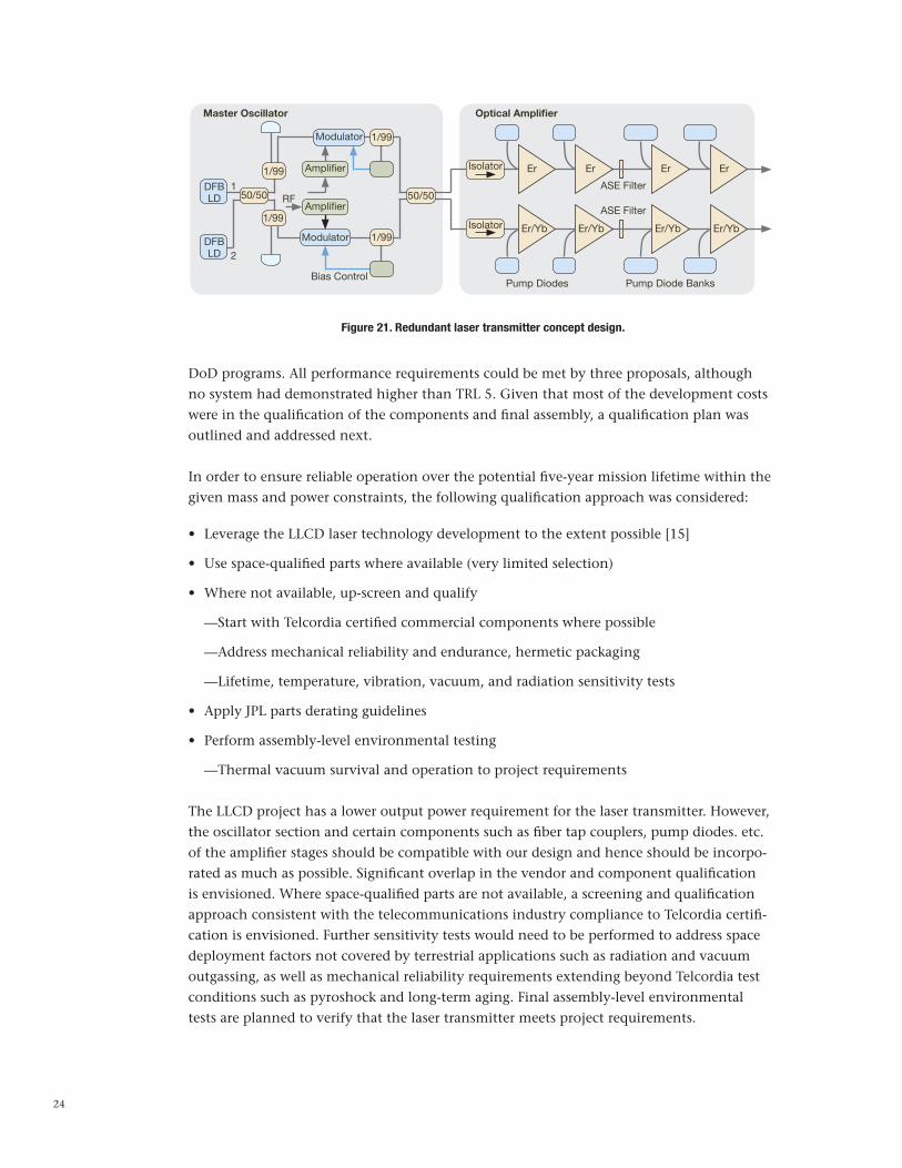
The conceptual design incorporates a continuous-wave DFB semiconductor laser with an external modulator to meet the high pulse extinction ratio requirement for PPM. The fiber amplifier comprises multiple stages of Er-doped fiber to mitigate amplified spontaneous emission (ASE) build-up and allow for isolation between the achievable gain in each stage. Co-doped Er-Yb fibers are used for the high-power sections. These fibers are pumped by high-reliability, 976-nm, multimode pump diodes, derated to increase their lifetime. A fully redundant approach is planned (Figure 21). Polarization-maintaining (PM) fiber is used throughout the design, although this increases the component development required for qualification compared to non-PM devices that have a stronger space heritage. The main driver for PM output is the increased background discrimination for near-Sun pointing at farthest range when the signal is polarized. Every dB of link margin counts in this most stressing situation.
Fiber-based amplifiers are peak-power-limited due to fiber nonlinearities such as stimulated Brillouin scattering (SBS) or stimulated Raman scattering (SRS). Increasing the pulse widths with high peak powers leads to pulse distortion and power loss, placing an upper limit on the achievable pulse width. The phonon lifetime for SBS is ~10 ns and represents the lowest threshold nonlinear process that has to be mitigated. Novel schemes such as phase modu-lating the input signal or fixed-pulse formats that limit the pulse width have been proposed and will be explored in more detail in the preliminary design phase [20]. Initial measure-ments on existing PPM fiber laser transmitters suggest an 8-ns pulse width is feasible with expanded large-mode-area fiber.
Several vendors were considered for developing the entire laser transmitter assembly based on their previous experience in developing flight laser transmitters for other NASA and
24
DoD programs. All performance requirements could be met by three proposals, although no system had demonstrated higher than TRL 5. Given that most of the development costs were in the qualification of the components and final assembly, a qualification plan was outlined and addressed next.
In order to ensure reliable operation over the potential five-year mission lifetime within the given mass and power constraints, the following qualification approach was considered:
• LeveragetheLLCDlasertechnologydevelopmenttotheextentpossible[15]
• Usespace-qualifiedpartswhereavailable(verylimitedselection)
• Wherenotavailable,up-screenandqualify
—Start with Telcordia certified commercial components where possible
—Address mechanical reliability and endurance, hermetic packaging
—Lifetime, temperature, vibration, vacuum, and radiation sensitivity tests
• ApplyJPLpartsderatingguidelines
• Performassembly-levelenvironmentaltesting
—Thermal vacuum survival and operation to project requirements
The LLCD project has a lower output power requirement for the laser transmitter. However, the oscillator section and certain components such as fiber tap couplers, pump diodes. etc. of the amplifier stages should be compatible with our design and hence should be incorpo-rated as much as possible. Significant overlap in the vendor and component qualification is envisioned. Where space-qualified parts are not available, a screening and qualification approach consistent with the telecommunications industry compliance to Telcordia certifi-cation is envisioned. Further sensitivity tests would need to be performed to address space deployment factors not covered by terrestrial applications such as radiation and vacuum outgassing, as well as mechanical reliability requirements extending beyond Telcordia test conditions such as pyroshock and long-term aging. Final assembly-level environmental tests are planned to verify that the laser transmitter meets project requirements.
Figure 21. Redundant laser transmitter concept design.
DFBLD
DFBLD
50/50 50/50
1/99
1/99
1/99
1/99
Modulator
Modulator
Amplifier
Amplifier
Optical AmplifierMaster Oscillator
Er Er Er Er
ASE Filter
ASE Filter
1
2
Isolator
Isolator Er/Yb Er/Yb Er/Yb Er/Yb
RF
Bias ControlPump Diodes Pump Diode Banks
25
A preliminary reliability analysis for the laser transmitter was performed at the component level based upon the plan to up-screen Telcordia certified components. This analysis in-corporated failure mechanisms from ineffectual screening of defects initially and wear-out failure mechanisms for end-of-life conditions. In between, approximations due to random defects were added to the risk model with derated parts and a redundant string of parts as well. Input for the risk model was from accelerated life test results of actual baselined com-ponents from vendors.
The reliability models used are
R e
R e
R t F F
R t F t
1 1
1
normalt
defect
combin defect normal
sys i
ct m
a a
=
=
= - + -
= -
m-
-
^ ^^^ ^
^
`
h h hh h
h
j
%
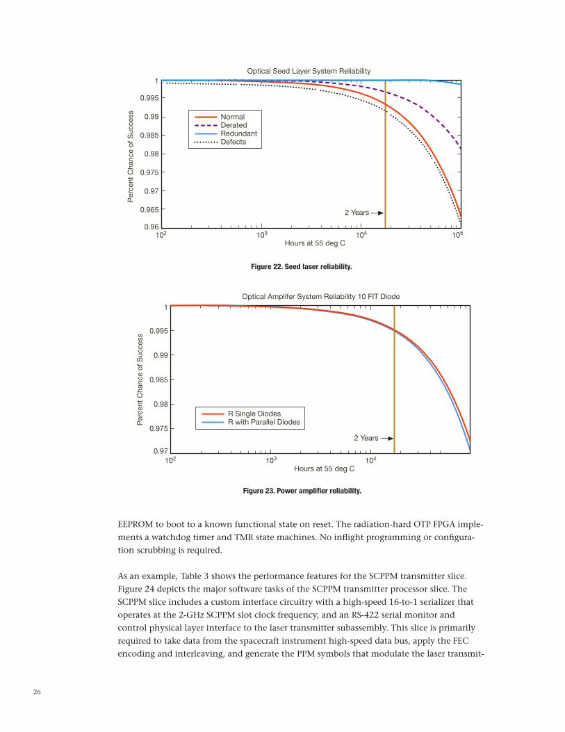
where m = constant failure rate at 55 deg C and 60 percent confidence; c = characteristic failure rate for defect population assuming 99 percent of defects will have failed by 3,000 hr — this reflects an unscreened population; c = time for 63 percent of population to fail, m = shape parameter (0.5) for decreasing failure rate, and a = percent of the population that is defective (0.1 percent). The defect populations were only assumed for the nonpas-sive RF amplifier and seed laser. Plotted as a function of time, the system reliability for the optical modulated seed laser and amplifier are seen in Figure 22 and Figure 23.
From this analysis, a five-year lifetime can be met with >98.5 percent chance of success with screened components or >98 percent with no early screening.
D. Modem and Controller
The modem and controller architecture baselined in Figure 10 comprises three networked processors. Each processor slice features a common digital core comprising a radiation-tolerant SPARC microprocessor, radiation-tolerant storage (volatile and nonvolatile), redundant serial communications links for interprocessor communications and spacecraft I/O, and a one-time-programmable (OTP) FPGA. Each slice features a small amount of cus-tomized I/O interface circuitry. Processor slice tasks execute within a simpler architecture with less overhead than would be encountered with a higher speed and complexity single-processor implementation. Each slice executes a threaded interrupt-driven architecture with high priorities given to critical tasks. Time-critical “accelerator” algorithms are hard-coded into the OTP FPGA. The result is a software-defined radio architecture that is truly software reprogrammable, not FPGA RAM bit-map reprogrammable. Both mass and power consump-tion are reduced in the DOT FLT architecture by eliminating the use of RAM-based FPGAs.
The SPARC LEON2 FT architecture features triple modular redundancy (TMR) and error detection and correction (EDAC) on SRAM and EEPROM storage for high radiation toler-ance (100 krad). Redundant monitor and control asynchronous serial busses are used for interprocess communications between slices. This architecture features a “safe” mode in
26
Figure 23. Power amplifier reliability.
Figure 22. Seed laser reliability.
102 103 104 105
Optical Seed Layer System Reliability
Per
cent
Cha
nce
of S
ucce
ss NormalDeratedRedundantDefects
2 Years
1
0.995
0.99
0.985
0.98
0.975
0.97
0.965
0.96
Hours at 55 deg C
102 103 104
Optical Amplifer System Reliability 10 FIT Diode
Per
cent
Cha
nce
of S
ucce
ss
R Single DiodesR with Parallel Diodes
2 Years
1
0.995
0.99
0.985
0.98
0.975
0.97
Hours at 55 deg C
EEPROM to boot to a known functional state on reset. The radiation-hard OTP FPGA imple-ments a watchdog timer and TMR state machines. No inflight programming or configura-tion scrubbing is required.
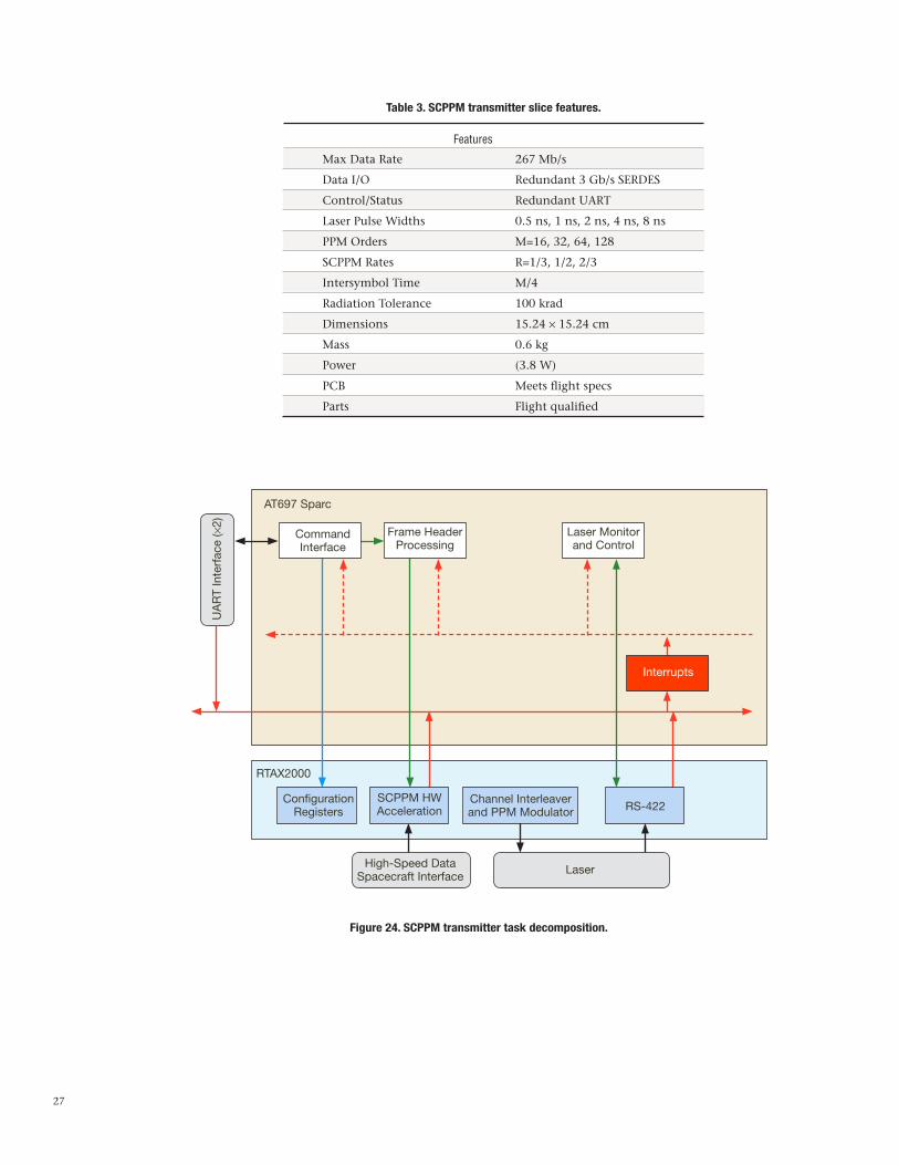
As an example, Table 3 shows the performance features for the SCPPM transmitter slice. Figure 24 depicts the major software tasks of the SCPPM transmitter processor slice. The SCPPM slice includes a custom interface circuitry with a high-speed 16-to-1 serializer that operates at the 2-GHz SCPPM slot clock frequency, and an RS-422 serial monitor and control physical layer interface to the laser transmitter subassembly. This slice is primarily required to take data from the spacecraft instrument high-speed data bus, apply the FEC encoding and interleaving, and generate the PPM symbols that modulate the laser transmit-
27
Max Data Rate 267 Mb/s
Data I/O Redundant 3 Gb/s SERDES
Control/Status Redundant UART
Laser Pulse Widths 0.5 ns, 1 ns, 2 ns, 4 ns, 8 ns
PPM Orders M=16, 32, 64, 128
SCPPM Rates R=1/3, 1/2, 2/3
Intersymbol Time M/4
Radiation Tolerance 100 krad
Dimensions 15.24 × 15.24 cm
Mass 0.6 kg
Power (3.8 W)
PCB Meets flight specs
Parts Flight qualified
Features
Table 3. SCPPM transmitter slice features.
AT697 Sparc
RTAX2000
ConfigurationRegisters
SCPPM HWAcceleration
Channel Interleaverand PPM Modulator RS-422
High-Speed DataSpacecraft Interface
Laser
UA
RT
Inte
rfac
e (×
2)
CommandInterface
Frame HeaderProcessing
Laser Monitorand Control
Interrupts
Figure 24. SCPPM transmitter task decomposition.
28
ter. This slice also controls and monitors the configuration and health of the laser transmit-ter subassembly over the RS-422 link, setting the pump laser drive currents and monitoring their temperatures, for instance.
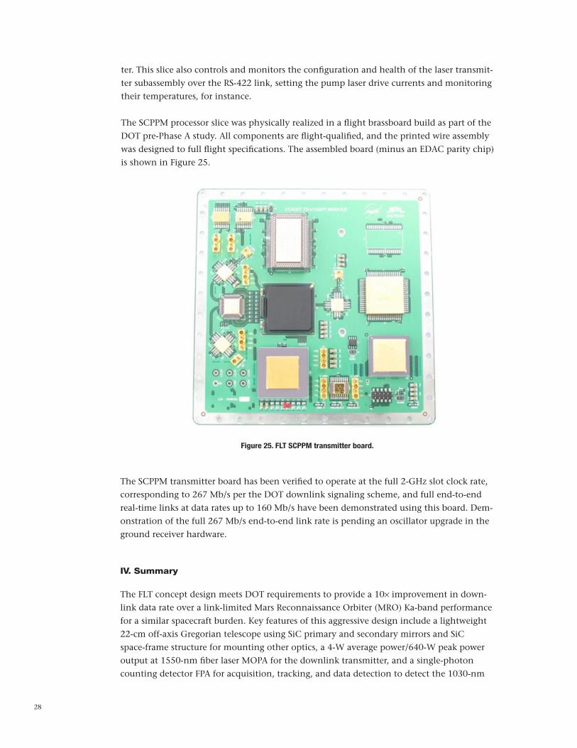
The SCPPM processor slice was physically realized in a flight brassboard build as part of the DOT pre-Phase A study. All components are flight-qualified, and the printed wire assembly was designed to full flight specifications. The assembled board (minus an EDAC parity chip) is shown in Figure 25.
Figure 25. FLT SCPPM transmitter board.
The SCPPM transmitter board has been verified to operate at the full 2-GHz slot clock rate, corresponding to 267 Mb/s per the DOT downlink signaling scheme, and full end-to-end real-time links at data rates up to 160 Mb/s have been demonstrated using this board. Dem-onstration of the full 267 Mb/s end-to-end link rate is pending an oscillator upgrade in the ground receiver hardware.
IV. Summary
The FLT concept design meets DOT requirements to provide a 10× improvement in down-link data rate over a link-limited Mars Reconnaissance Orbiter (MRO) Ka-band performance for a similar spacecraft burden. Key features of this aggressive design include a lightweight 22-cm off-axis Gregorian telescope using SiC primary and secondary mirrors and SiC space-frame structure for mounting other optics, a 4-W average power/640-W peak power output at 1550-nm fiber laser MOPA for the downlink transmitter, and a single-photon counting detector FPA for acquisition, tracking, and data detection to detect the 1030-nm

29
DOT uplink beacon. Spacecraft disturbances are mitigated by a low-mass, low-power hybrid passive/active isolation platform. An innovative networked modem and C&DH proces-sor architecture is proposed to meet data-processing requirements with minimal mass and power. Preliminary reliability analysis indicates that the five-year mission lifetime require-ment can be met with a high degree of confidence. Although low-TRL systems for the disturbance-rejection assembly, downlink transmitter, and uplink receiver were selected to meet aggressive mass and power requirements with adequate margin, high-TRL backups are available for these assemblies should proposed technology development not mature these assemblies sufficiently by a project Preliminary Design Review (PDR). In some cases, use of these high-TRL backups would require rescop-ing of level 2 or lower requirements, along with an expected increase in system mass and power.
Acknowledgments
Special thanks go to Abhijit Biswas, Kevin Quirk, Kevin Birnbaum, and Bruce Moision for their contributions to FLT system engineering; Tom Roberts for telescope and optics design; Gerry Ortiz and Virginio Sannibale for development work of the low-frequency vibration-isolation platform prototype; Heidi Becker, Michael Cherng, and Richard Harris for their contributions to understanding the radiation effects for the photon counting detector array; Suzana Sburlan for breadboard development of beacon centroiding using a photon counting detector array; Huy Nguyen and Ferze Patawaran for their contributions to devel-opment of the SCPPM transmitter brassboard; and Stephen Townes, Dimitisos Antsos, and Hamid Hemmati for requirements development.
References
[1] J. Taylor, D. K. Lee, and S. Shambayati, “Mars Reconnaissance Orbiter Telecommuni-cations,” Deep Space Communication and Navigation Center of Excellence (DESCANSO)
Design and Performance Summary Series, Jet Propulsion Laboratory, Pasadena, California, September 2006.
[2] G. G. Ortiz, S. Lee, and J. W. Alexander, “Submicroradian Pointing for Deep Space Optical Telecommunications Network,” 19th AIAA International Communications Satellite Systems Conference, Toulouse, France, 2001.
[3] K. M. Birnbaum, Y. Chen and H. Hemmati, “Precision Optical Ranging by Paired One-Way Time of Flight,” Proceedings of SPIE, Free-Space Laser Communication Technolo-gies XXII, vol. 7587, p. 75870A, February 2010.
[4] H. Hemmati, editor, Deep Space Optical Communications, New Jersey: John Wiley & Sons, Interscience, p. 110, 369–370, 2006.
[5] M. W. Wright and George C. Valley, “Yb-doped Fiber Amplifier for Deep-Space Opti-cal Communications,” Journal of Lightwave Technology, vol. 23, pp. 1369–1374, March 2005.

30
[6] A. Biswas et al., “Palomar Receive Terminal for the Mars Laser Communication Demon-stration Project,” Proceedings of the IEEE, vol. 95, no. 10, pp. 2045–2058, 2007
[7] B. Moision and J. Hamkins, “Coded Modulation for the Deep-Space Optical Channel: Serially Concatenated Pulse-Position Modulation,” The Interplanetary Network Progress
Report, vol. 42-161, Jet Propulsion Laboratory, Pasadena, California, pp. 1–25, May 15, 2005. http://ipnpr.jpl.nasa.gov/progress_report/42-161/161T.pdf
[8] K. J. Quirk, J. W. Gin, and M. Srinivasan, “Optical PPM Synchronization for Photon Counting Receivers,” Military Communications Conference, 2008 (MILCOM 2008) IEEE , pp. 1–7, November 16–19, 2008.
[9] J. B. Berner, S. H. Bryant, and P. W. Kinman, “Range Measurement as Practiced in the Deep Space Network,” Proceedings of the IEEE, vol. 95, no. 11, pp. 2202–2214, 2007.
[10] M. W. Wright, “Robust Short-Pulse High-Peak-Power Laser Transmitter for Optical Communications,” Proceedings of SPIE, Free-Space Laser Communication Technologies XXI, vol. 7199, p. 71990C, February 2009.
[11] G. G. Ortiz and W. H. Farr, “Two-Photon Absorption Long-Wavelength Optical Beam Tracking,” The Interplanetary Network Progress Report, vol. 42-173, Jet Propulsion Labora-tory, Pasadena, California, pp. 1–13, May 15, 2008. http://ipnpr.jpl.nasa.gov/progress_report/42-173/173C.pdf
[12] R. D. Harris, W. H. Farr, and H. N. Becker, “Degradation of InP-Based Geiger-Mode Ava-lanche Photodiodes due to Proton Irradiation,” Journal of Modern Optics, vol. 58, no. 3, pp. 225–232, January 2011 (first published November 23, 2010).
[13] G. G. Ortiz, W. H. Farr, J. R. Charles, W. T. Roberts, V. Sannibale, J. Gin, A. Sahasrabud-he, and V. Garkanian, “Canonical Deep Space Optical Communications Transceiver,” Proceedings of SPIE, Free-Space Laser Communication Technologies XXI, vol. 7199, p. 71990K, January 2009.
[14] H. Hemmati, Y. Chen, S. Lee, and G. G. Ortiz, “Earth-Image Tracking in the IR for Deep Space Optical Communications,” IEEE LEOS (Lasers and Electro-Optics Society) Newsletter, vol. 19, no. 5, pp. 18–19, October 2005.
[15] S. Constantine, L. E. Elgin, M. L. Stevens, and J. A. Greco, “Design of a High-Speed Space Modem for the Lunar Laser Communications Demonstration,” Proceedings of
SPIE, Free-Space Laser Communications Technologies XXIII, vol. 7923, p. 792308, Feb-ruary 2011.
[16] M. Ghioni, G. Armellini, P. Maccagnani, I. Rech, M. K. Emsley and S. Ünlü, “Resonant-Cavity-Enhanced Single-Photon Avalanche Diodes on Reflecting Silicon Substrates,” IEEE Photonics Technology Letters, vol. 20, no. 6, p. 413–415, March 15, 2008.
[17] A. Biswas, H. Hemmati, S. Piazzolla, B. Moision, K. Birnbaum, and K. Quirk, “Deep-space Optical Terminals (DOT) Systems Engineering,” The Interplanetary Network
Progress Report, vol. 42-183, Jet Propulsion Laboratory, Pasadena, California, pp. 1–38, November 15, 2010. http://ipnpr.jpl.nasa.gov/progress_report/42-183/183A.pdf

31
[18] W. H. Farr, “Negative Avalanche Feedback Detectors for Photon-Counting Optical Communications,” Proceedings of SPIE, Free-Space Laser Communication Technologies XXI, vol. 7199, p. 71990Q, January 2009.
[19] B. Moision and W. Farr, “Communication Limits Due to Photon Detector Jitter,” IEEE
Photonics Technology Letters, vol. 20, no. 9, May 2008.
[20] N. Spellmeyer, D. Boroson, D. Caplan, B. Robinson, and M. Stevens, “Simple SBS-Miti-gating Waveforms for High-Power PPM Transmitters for Space Laser Communications,” Conference on Lasers and Electro-Optics/Quantum Electronics and Laser Science Con-ference and Photonic Applications Systems Technologies, Optical Society of America, Baltimore, Maryland, May 6, 2007.