Embed Size (px)
Citation preview
Overview and History of the
Taum Sauk Pumped Storage Project
Reynolds County, Missouri
J. David Rogers, Conor Watkins, and David J. Hoffman
Missouri University of Science and Technology – Rolla, MO
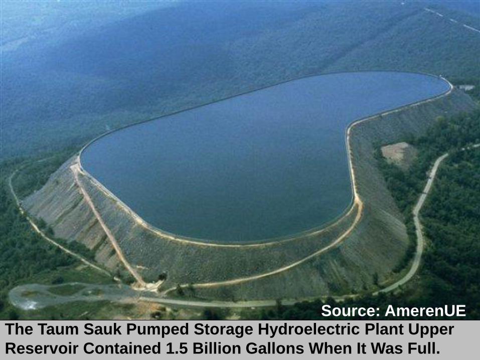
The Taum Sauk Pumped Storage Hydroelectric Plant Upper
Reservoir Contained 1.5 Billion Gallons When It Was Full.
Source: AmerenUE

Geologic & Geographic
Setting • The Taum Sauk Pumped Storage Hydroelectric Plant is
located in in the St. Francois Mountains, about 90 mi SW of St. Louis.
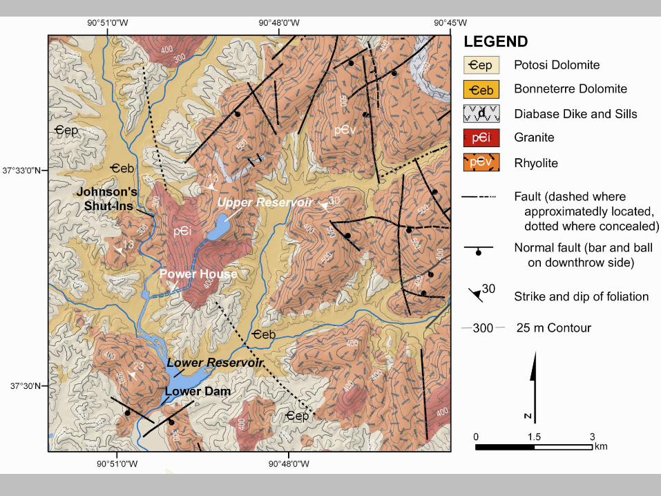
• These mountains are underlain by Precambrian igneous knobs with margins draped in Cambrian & Ordovician sedimentary rocks, mostly carbonates.
• The Ozarks were not glaciated during the Pleistocene. The absence of glaciation allowed zones of deep weathering and development of residuum.
• The topographic relief of this area made it attractive for pumped storage schemes.
• The lower reservoir was formed by damming the East Fork of the Black River near Lesterville, MO.
• The upper reservoir was constructed atop Proffit Mountain, Missouri’s 6th highest point. The mountaintop was blasted off and the resulting materials were used to form a kidney shaped dike about 90 feet high, capped by a 10 foot concrete parapet wall.
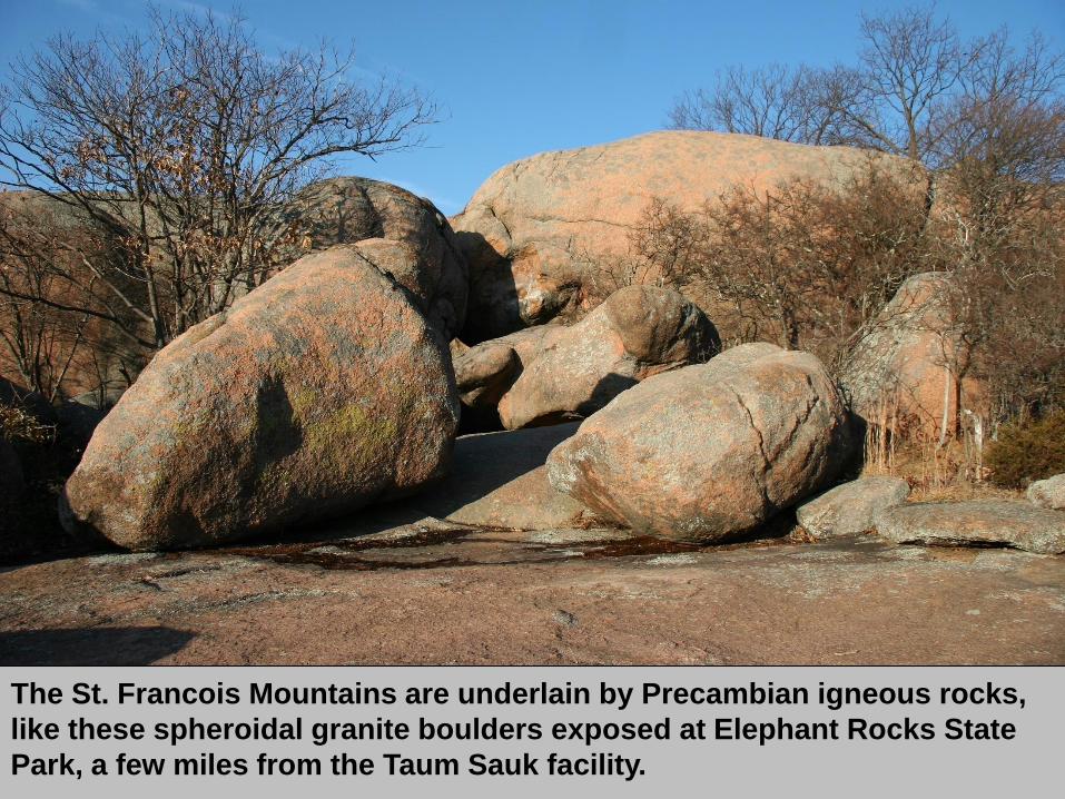
The St. Francois Mountains are underlain by Precambian igneous rocks,
like these spheroidal granite boulders exposed at Elephant Rocks State
Park, a few miles from the Taum Sauk facility.
• The project was designed and constructed
Sverdrup-Parcel & Associates along with
numerous sub-contractors
• The plant was one of the first pumped storage
projects in the United States when it went into
service in 1963.
• The lower storage reservoir was situated on the
East Fork of the Black River, just downstream of
Johnson’s Shut-ins State Park.
• Water was pumped uphill through a 7,000 ft long
tunnel to the upper reservoir, an 800 ft lift.
Early History
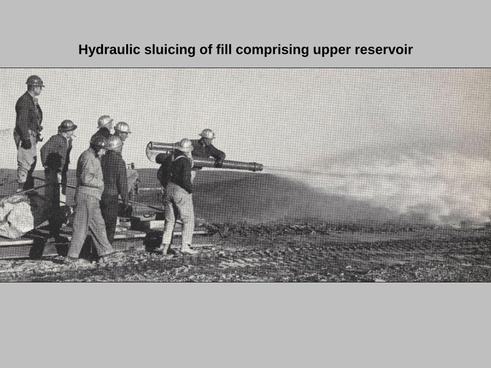
Hydraulic sluicing of fill comprising upper reservoir
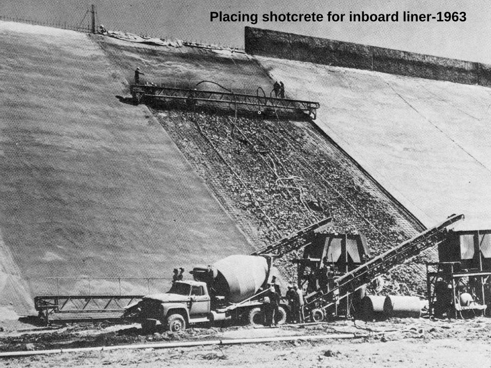
Placing shotcrete for inboard liner-1963
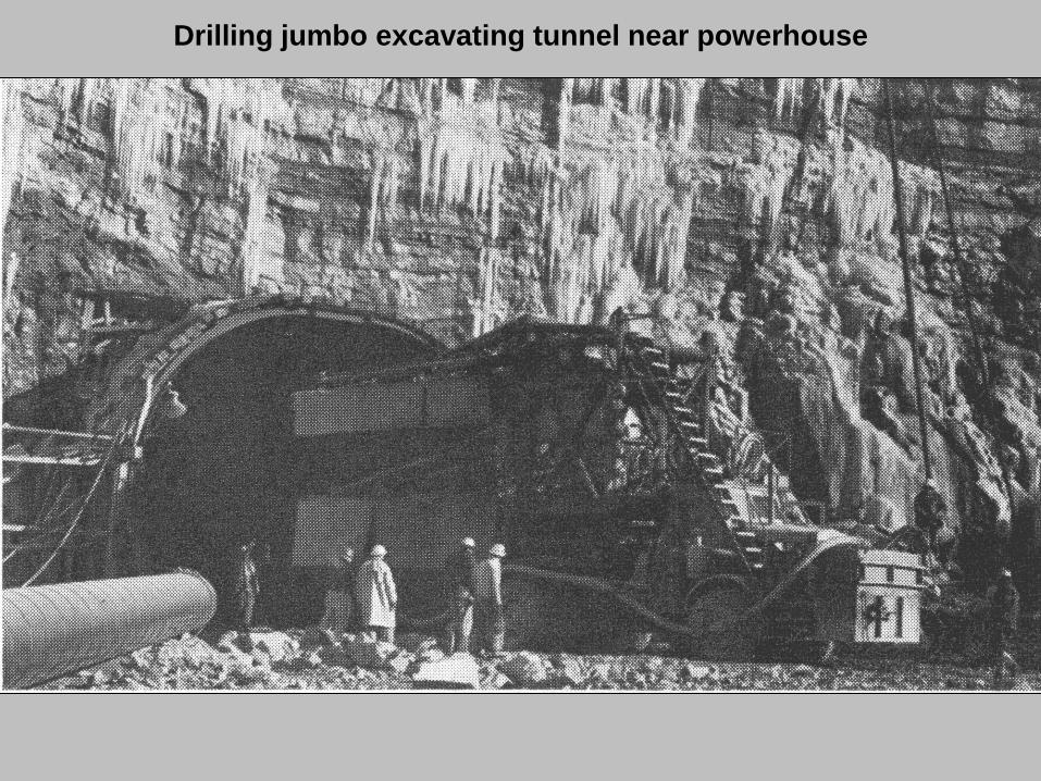
Drilling jumbo excavating tunnel near powerhouse

Project wins civil engineering award in 1964
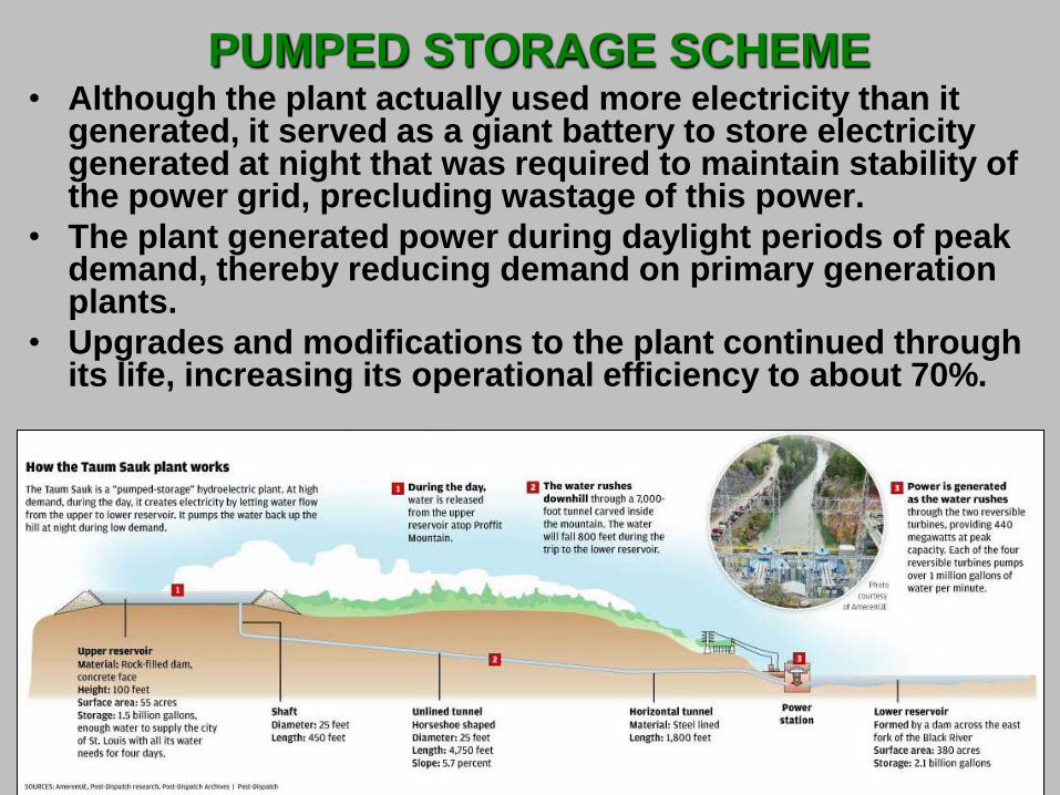
PUMPED STORAGE SCHEME • Although the plant actually used more electricity than it
generated, it served as a giant battery to store electricity generated at night that was required to maintain stability of the power grid, precluding wastage of this power.
• The plant generated power during daylight periods of peak demand, thereby reducing demand on primary generation plants.
• Upgrades and modifications to the plant continued through its life, increasing its operational efficiency to about 70%.
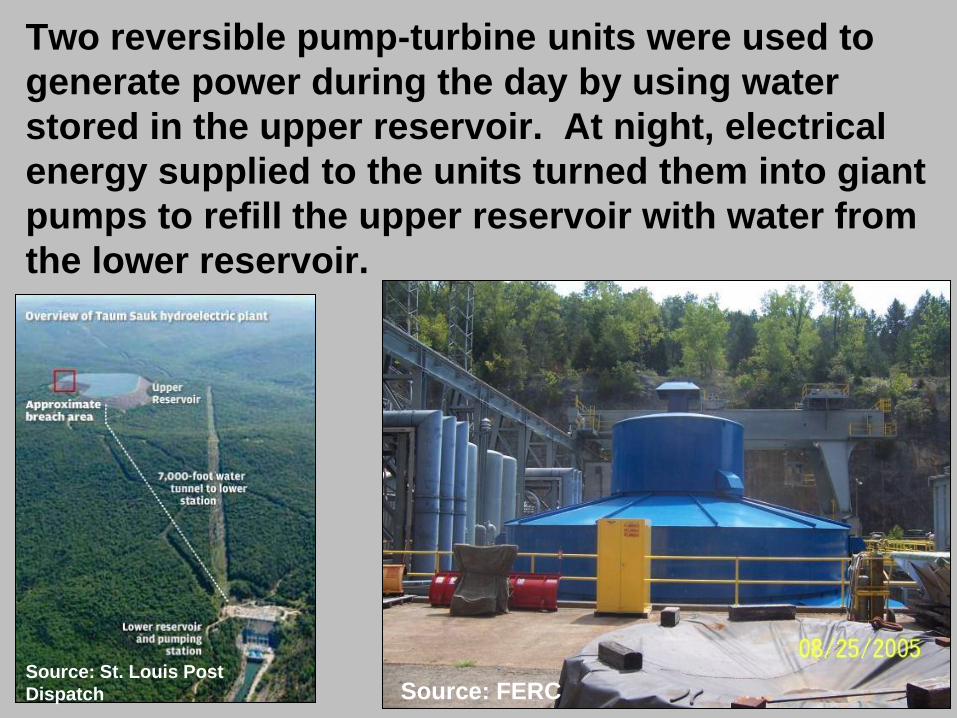
Two reversible pump-turbine units were used to
generate power during the day by using water
stored in the upper reservoir. At night, electrical
energy supplied to the units turned them into giant
pumps to refill the upper reservoir with water from
the lower reservoir.
Source: FERC Source: St. Louis Post
Dispatch
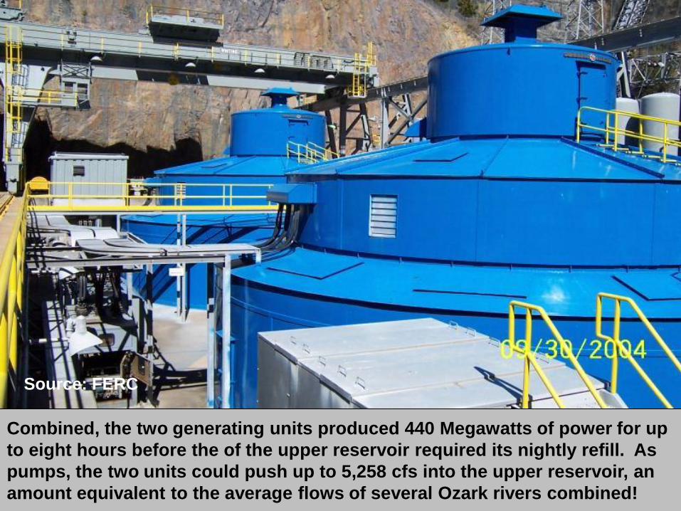
Combined, the two generating units produced 440 Megawatts of power for up
to eight hours before the of the upper reservoir required its nightly refill. As
pumps, the two units could push up to 5,258 cfs into the upper reservoir, an
amount equivalent to the average flows of several Ozark rivers combined!
Source: FERC
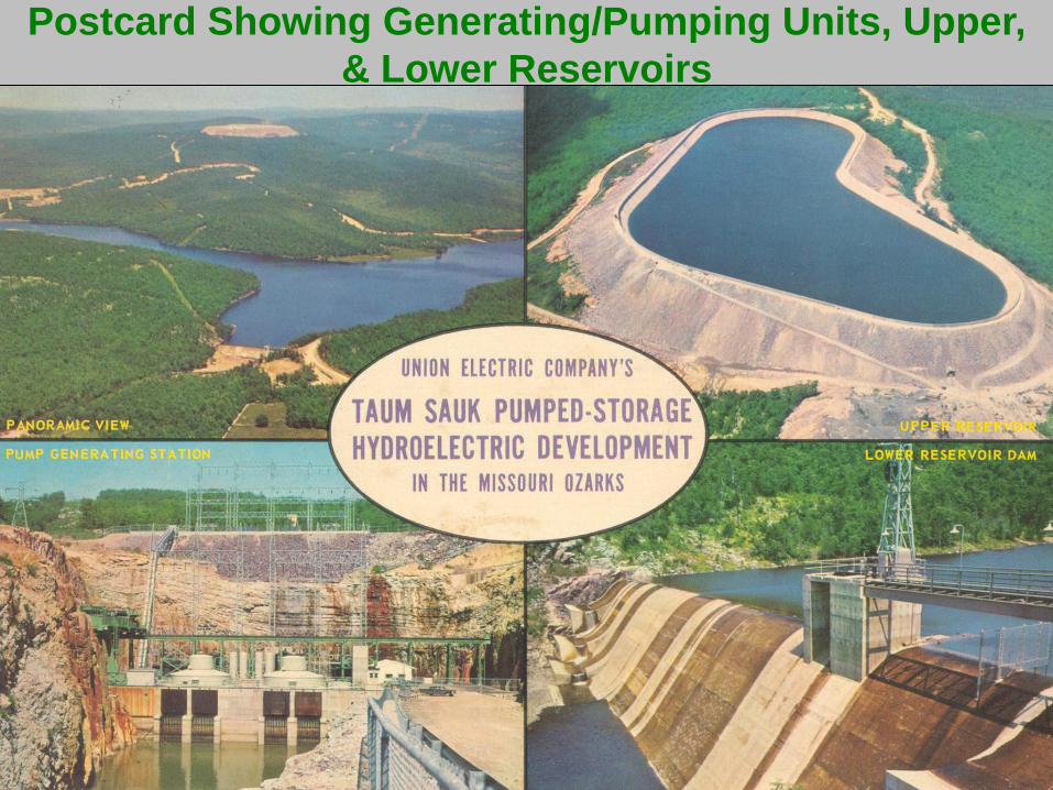
Postcard Showing Generating/Pumping Units, Upper,
& Lower Reservoirs
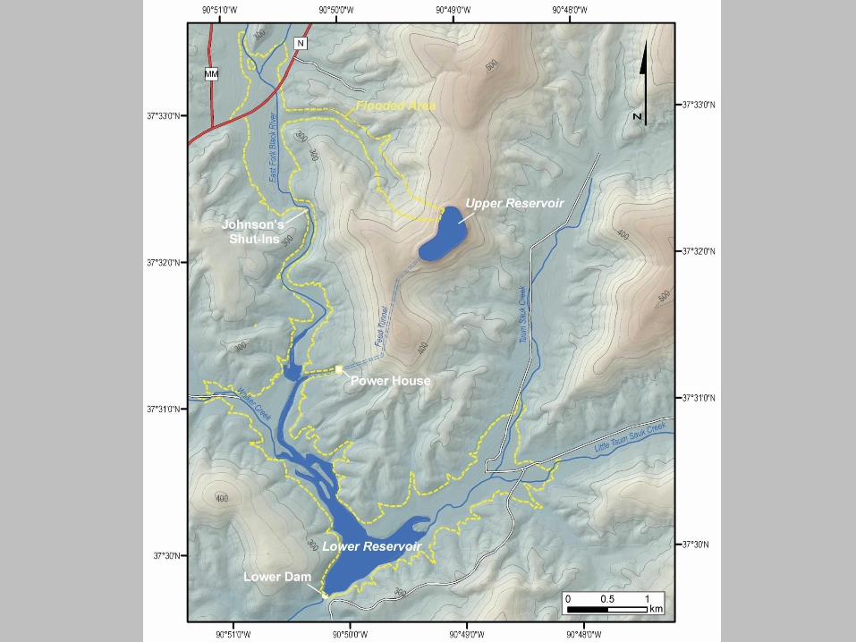
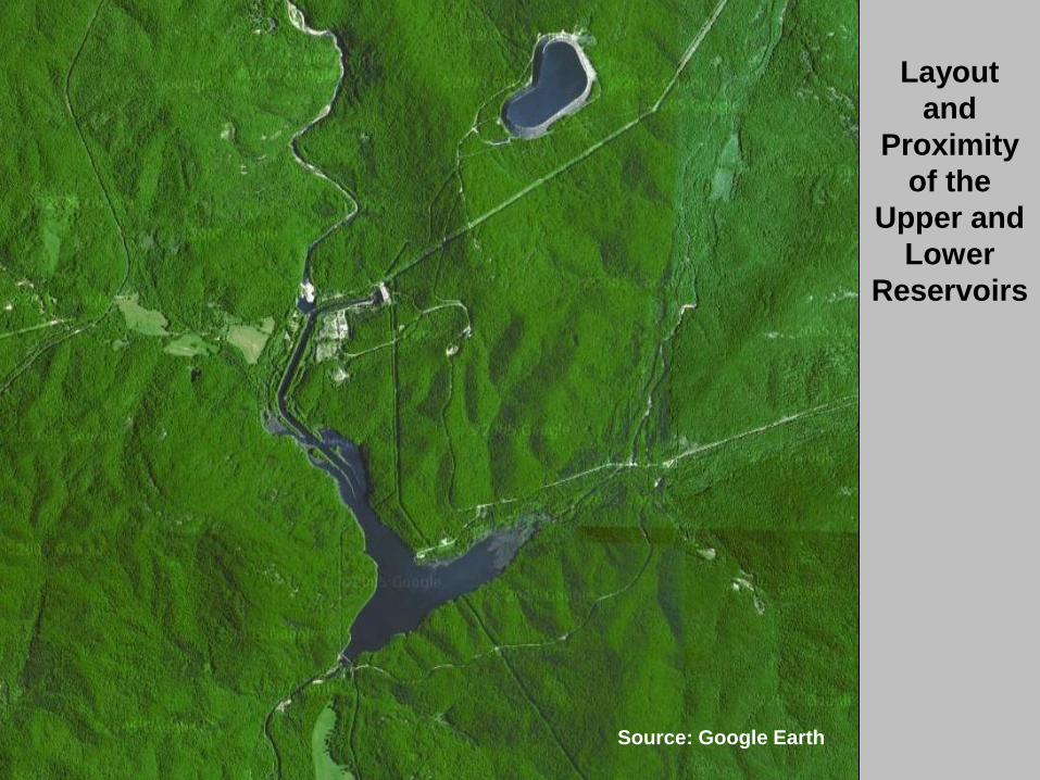
Layout
and
Proximity
of the
Upper and
Lower
Reservoirs
Source: Google Earth
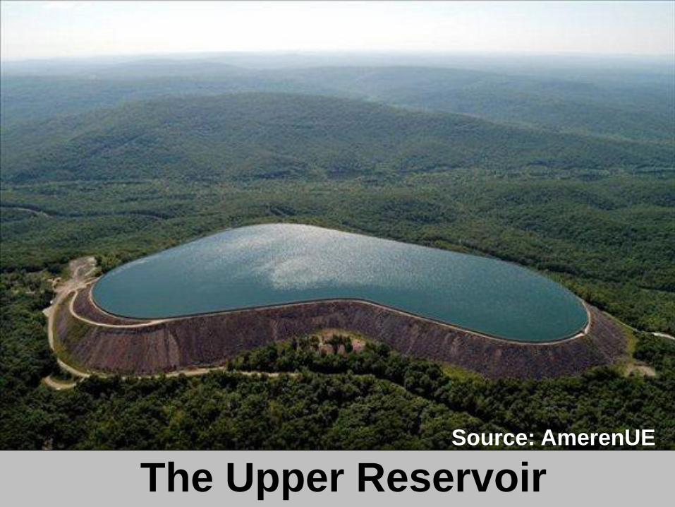
Source: AmerenUE
The Upper Reservoir
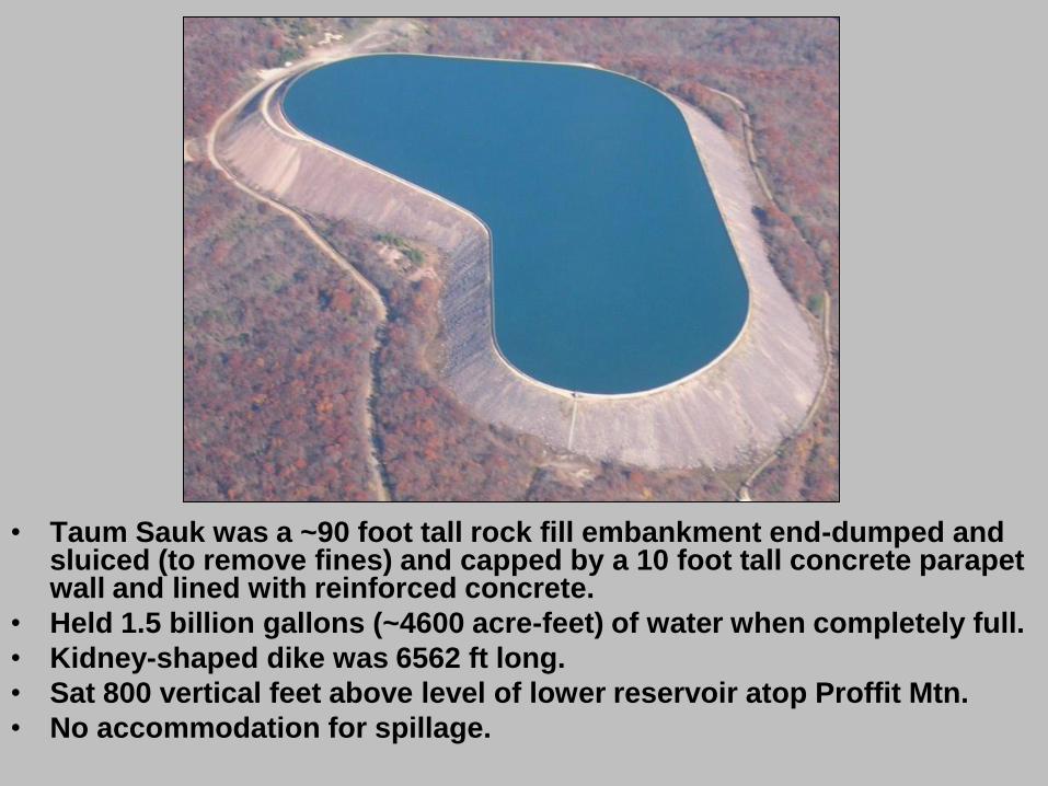
• Taum Sauk was a ~90 foot tall rock fill embankment end-dumped and sluiced (to remove fines) and capped by a 10 foot tall concrete parapet wall and lined with reinforced concrete.
• Held 1.5 billion gallons (~4600 acre-feet) of water when completely full.
• Kidney-shaped dike was 6562 ft long.
• Sat 800 vertical feet above level of lower reservoir atop Proffit Mtn.
• No accommodation for spillage.
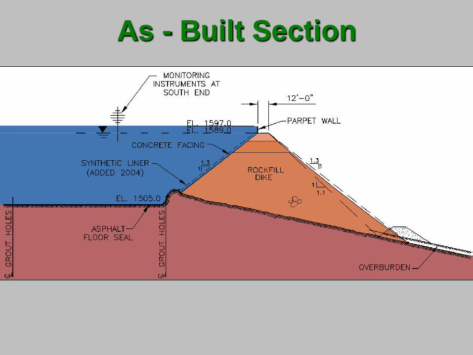
As - Built Section
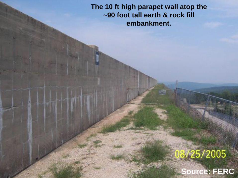
The 10 ft high parapet wall atop the
~90 foot tall earth & rock fill
embankment.
Source: FERC
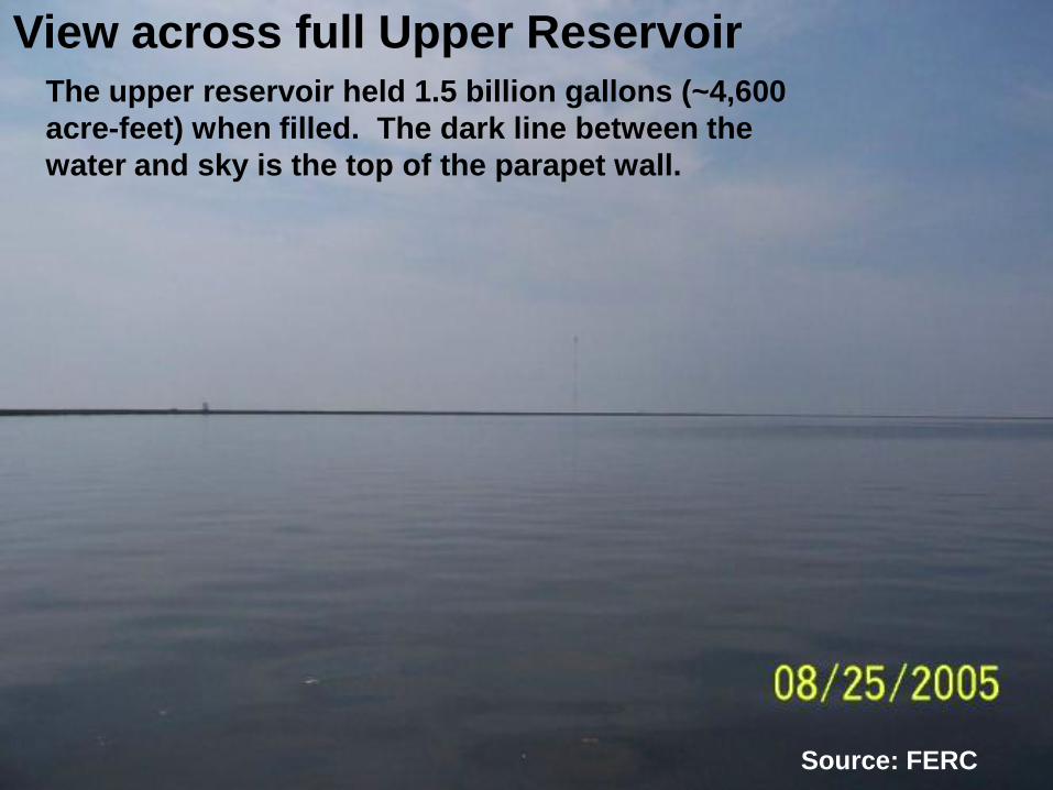
Source: FERC
The upper reservoir held 1.5 billion gallons (~4,600
acre-feet) when filled. The dark line between the
water and sky is the top of the parapet wall.
View across full Upper Reservoir

DIFFERENTIAL
SETTLEMENT
OF THE
RING DIKE
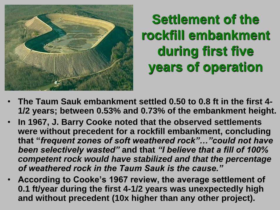
• The Taum Sauk embankment settled 0.50 to 0.8 ft in the first 4-1/2 years; between 0.53% and 0.73% of the embankment height.
• In 1967, J. Barry Cooke noted that the observed settlements were without precedent for a rockfill embankment, concluding that “frequent zones of soft weathered rock”…”could not have been selectively wasted” and that “I believe that a fill of 100% competent rock would have stabilized and that the percentage of weathered rock in the Taum Sauk is the cause.”
• According to Cooke’s 1967 review, the average settlement of 0.1 ft/year during the first 4-1/2 years was unexpectedly high and without precedent (10x higher than any other project).
Settlement of the
rockfill embankment
during first five
years of operation
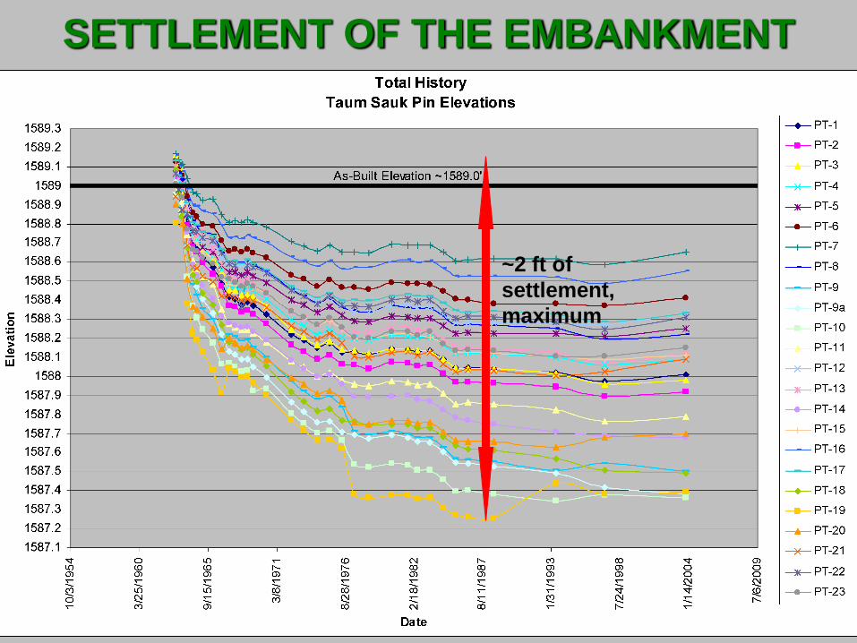
SETTLEMENT OF THE EMBANKMENT
~2 ft of
settlement,
maximum
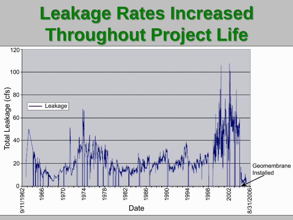
Leakage Rates Increased
Throughout Project Life
Deregulation & Upgrades • Prior to the deregulation of the electric power industry in the
mid-1990’s, Taum Sauk was operated approximately 100 days a year, mostly during the hot summer months when air conditioning demand was high.
• After 1995, power was allowed to be sold on the spot (open) market at non-regulated rates, making it profitable to operate Taum Sauk year-round. This provided an incentive to shut the plant down as little as possible.
• The generator/pump units were replaced in 1999 with increased capacity and more efficient units to increase profitability of the plant. Maximum output increased from 350 MW to 440 MW.
• An HDPE seepage liner was
added to the reservoir in 2004 at a cost of $2.4 million to
reduce chronic leakage.
Upper Reservoir Experienced
Persistent Leaks • Throughout its life, the upper reservoir leaked, especially
in the vicinity of the failure. This leakage helped provide swimmers at nearby Johnson’s Shut-ins State Park with a steady source of water during dry summers.
• At least five leaks were serious enough to require the the shut-down of the plant during their repair. The plant operated only 6 months out of its first year of use because of needed repairs.
• Most leaks were related to the cracking of the reinforced concrete liner as the underlying rockfill settled differentially.
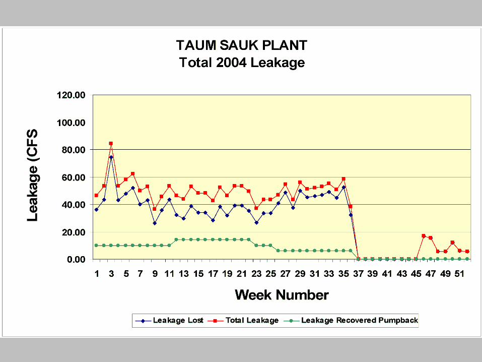
• Leakage was reducing the efficiency of the operation by about 2% and the reservoir was lined with an HDPE geomembrane in fall 2004. This reduced leakage dramatically.
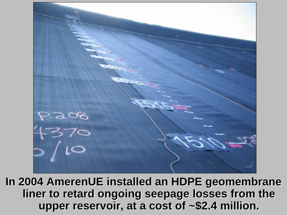
In 2004 AmerenUE installed an HDPE geomembrane liner to retard ongoing seepage losses from the
upper reservoir, at a cost of ~$2.4 million.
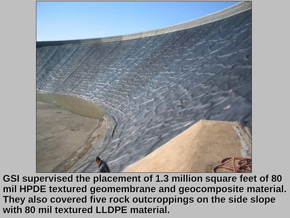
GSI supervised the placement of 1.3 million square feet of 80 mil HPDE textured geomembrane and geocomposite material. They also covered five rock outcroppings on the side slope with 80 mil textured LLDPE material.
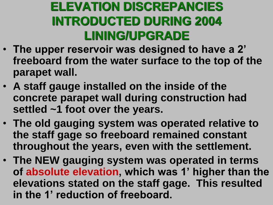
ELEVATION DISCREPANCIES
INTRODUCTED DURING 2004
LINING/UPGRADE • The upper reservoir was designed to have a 2’
freeboard from the water surface to the top of the parapet wall.
• A staff gauge installed on the inside of the concrete parapet wall during construction had settled ~1 foot over the years.
• The old gauging system was operated relative to the staff gage so freeboard remained constant throughout the years, even with the settlement.
• The NEW gauging system was operated in terms of absolute elevation, which was 1’ higher than the elevations stated on the staff gage. This resulted in the 1’ reduction of freeboard.
CHANGES TO
RESERVOIR STAGE
SENSOR SYSTEM
DURING 2004
LINING/UPGRADE
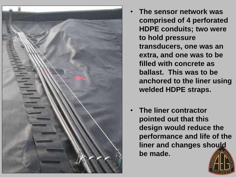
• The sensor network was
comprised of 4 perforated
HDPE conduits; two were
to hold pressure
transducers, one was an
extra, and one was to be
filled with concrete as
ballast. This was to be
anchored to the liner using
welded HDPE straps.
• The liner contractor
pointed out that this
design would reduce the
performance and life of the
liner and changes should
be made.
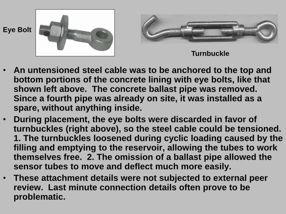
• An untensioned steel cable was to be anchored to the top and bottom portions of the concrete lining with eye bolts, like that shown left above. The concrete ballast pipe was removed. Since a fourth pipe was already on site, it was installed as a spare, without anything inside.
• During placement, the eye bolts were discarded in favor of turnbuckles (right above), so the steel cable could be tensioned. 1. The turnbuckles loosened during cyclic loading caused by the filling and emptying to the reservoir, allowing the tubes to work themselves free. 2. The omission of a ballast pipe allowed the sensor tubes to move and deflect much more easily.
• These attachment details were not subjected to external peer review. Last minute connection details often prove to be problematic.
Turnbuckle
Eye Bolt
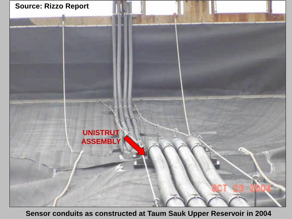
Sensor conduits as constructed at Taum Sauk Upper Reservoir in 2004
UNISTRUT
ASSEMBLY
Source: Rizzo Report

The Institute of Electrical and
Electronics Engineers (IEEE) Declares
The Taum Sauk Plant An Engineering
Milestone – Sept. 26, 2005 The plant was recognized for the following reasons…
• The plant was the largest in North America and one of the first of its type when it was constructed in 1963.
• Used high capacity turbine generators/pumps.
• Ability to be run remotely from St. Louis or Osage/Bagnell Dam Power Plant or automatically WITHOUT HUMAN INTERVENTION.
• Ability to help restart the power grid in the event of a complete blackout as coal and nuclear plants need outside power to start.
• Only ~75 engineering projects worldwide have received this award.
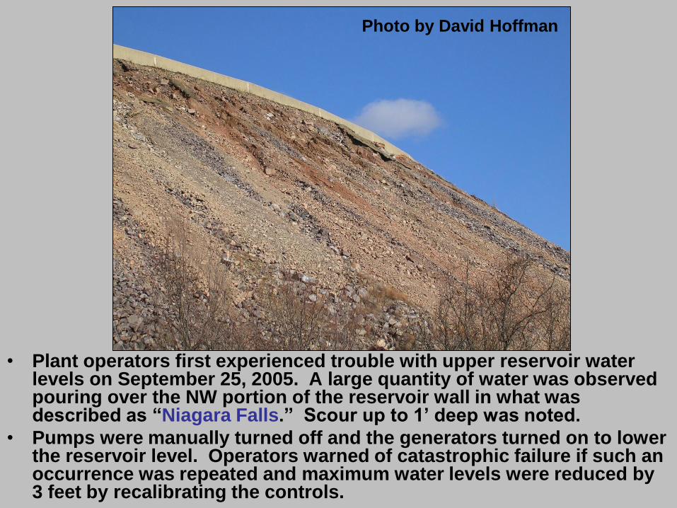
• Plant operators first experienced trouble with upper reservoir water levels on September 25, 2005. A large quantity of water was observed pouring over the NW portion of the reservoir wall in what was described as “Niagara Falls.” Scour up to 1’ deep was noted.
• Pumps were manually turned off and the generators turned on to lower the reservoir level. Operators warned of catastrophic failure if such an occurrence was repeated and maximum water levels were reduced by 3 feet by recalibrating the controls.
Photo by David Hoffman

Warnings Sent By Plant Operator
Regarding Sept. 25th, 2005 “Niagara
Falls” Overtopping • Richard Cooper, Plant Operator, sent an e-mail to his
supervisors warning about continued overtopping of the upper reservoir two days after the incident. Inspections revealed rockfill below the concrete wall had been scoured and eroded up to 1 foot during this event.
• "Overflowing the upper reservoir is obviously an absolute 'NO-NO,'"
• "The dam would severely erode and cause eventual failure of the dam. Those kinds of headlines we don't need.“
• If water continued to spill over the top of the wall, it could cause a section to collapse and “then it would be all down hill from there — literally.”
• Divers were called in and determined that the sensors were loose at the bottom of the reservoir. Maximum water levels in the reservoir were reduced by 3 feet to provide a margin of error. Permanent repairs would be postponed until other regular scheduled maintenance to avoid an additional shutdown of the facility.
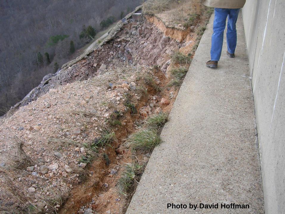
Photo by David Hoffman
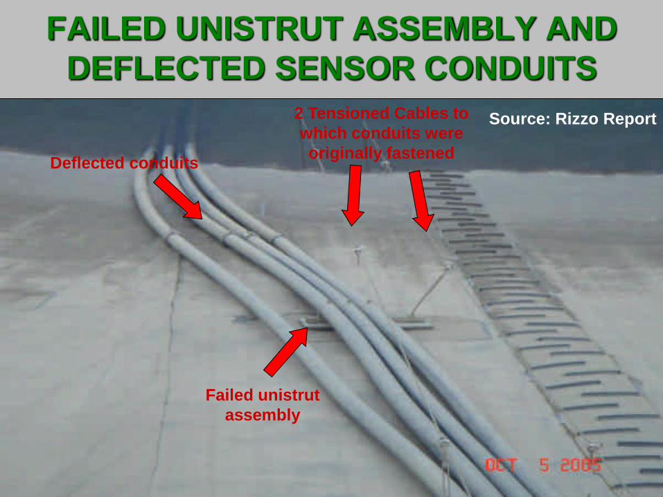
FAILED UNISTRUT ASSEMBLY AND
DEFLECTED SENSOR CONDUITS
Deflected conduits
2 Tensioned Cables to
which conduits were
originally fastened
Failed unistrut
assembly
Source: Rizzo Report

"Overflowing the upper reservoir is obviously an absolute 'NO-NO,'"
"The dam would severely erode and cause eventual failure of the dam. Those
kinds of headlines we don't need.“
If water continued to spill over the top of the wall, it could cause a section to
collapse and “then it would be all down hill from there — literally.”


![In the Appalacian Region August 2009 Lexington, KY · 12/14/2005 · – – Johnson Shut-ins State Park – ... FERC Website Information – [search Taum Sauk] –Executive Summary](https://img.pdfslide.net/doc/110x75/5fed79c0940d6c10ca42d51c/in-the-appalacian-region-august-2009-lexington-ky-12142005-a-a-johnson.jpg)