Embed Size (px)
Citation preview
OVERVIEW OF THE CURRENT STATE AND DEVELOPMENT OF CO2
CAPTURE TECHNOLOGIES IN THE IRONMAKING PROCESS
Report: 2013/TR3
April 2013
INTERNATIONAL ENERGY AGENCY The International Energy Agency (IEA) was established in 1974 within the framework of the Organisation for Economic Co-operation and Development (OECD) to implement an international energy programme. The IEA fosters co-operation amongst its 28 member countries and the European Commission, and with the other countries, in order to increase energy security by improved efficiency of energy use, development of alternative energy sources and research, development and demonstration on matters of energy supply and use. This is achieved through a series of collaborative activities, organised under more than 40 Implementing Agreements. These agreements cover more than 200 individual items of research, development and demonstration. IEAGHG is one of these Implementing Agreements.
DISCLAIMER
The views and opinions of the authors expressed herein do not necessarily reflect those of the IEAGHG, its members, the International Energy Agency, the organisations listed below, nor any employee or persons acting on behalf of any of them. In addition, none of these make any warranty, express or implied, assumes any liability or responsibility for the accuracy, completeness or usefulness of any information, apparatus, product of process disclosed or represents that its use would not infringe privately owned rights, including any parties intellectual property rights. Reference herein to any commercial product, process, service or trade name, trade mark or manufacturer does not necessarily constitute or imply any endorsement, recommendation or any favouring of such products.
COPYRIGHT
Copyright © IEA Environmental Projects Ltd. (IEAGHG) 2013. All rights reserved.
ACKNOWLEDGEMENTS AND CITATIONS This report describes research sponsored by IEAGHG. This report was prepared by:
• Stanley Santos The report should be cited in literature as follows: ‘IEAGHG, “Overview to the Current State and Development of CO2 Capture Technologies in the Ironmaking Process”, 2013/TR3, April 2013.’ Further information or copies of the report can be obtained by contacting IEAGHG at: IEAGHG, Orchard Business Centre, Stoke Orchard, Cheltenham, GLOS., GL52 7RZ, UK Tel: +44(0) 1242 680753 Fax: +44 (0)1242 680758 E-mail: [email protected] Internet: www.ieaghg.org
CO2 Capture Technologies in Ironmaking Process – Technical Overview Page 1 of 40
IRON AND STEEL INDUSTRY Overview of the Current State and Development of CO2 Capture Technologies in
Ironmaking Process
Stanley Santos IEA Greenhouse Gas R&D Programme
Orchard Business Centre Stoke Orchard
Cheltenham, UK
INTRODUCTION
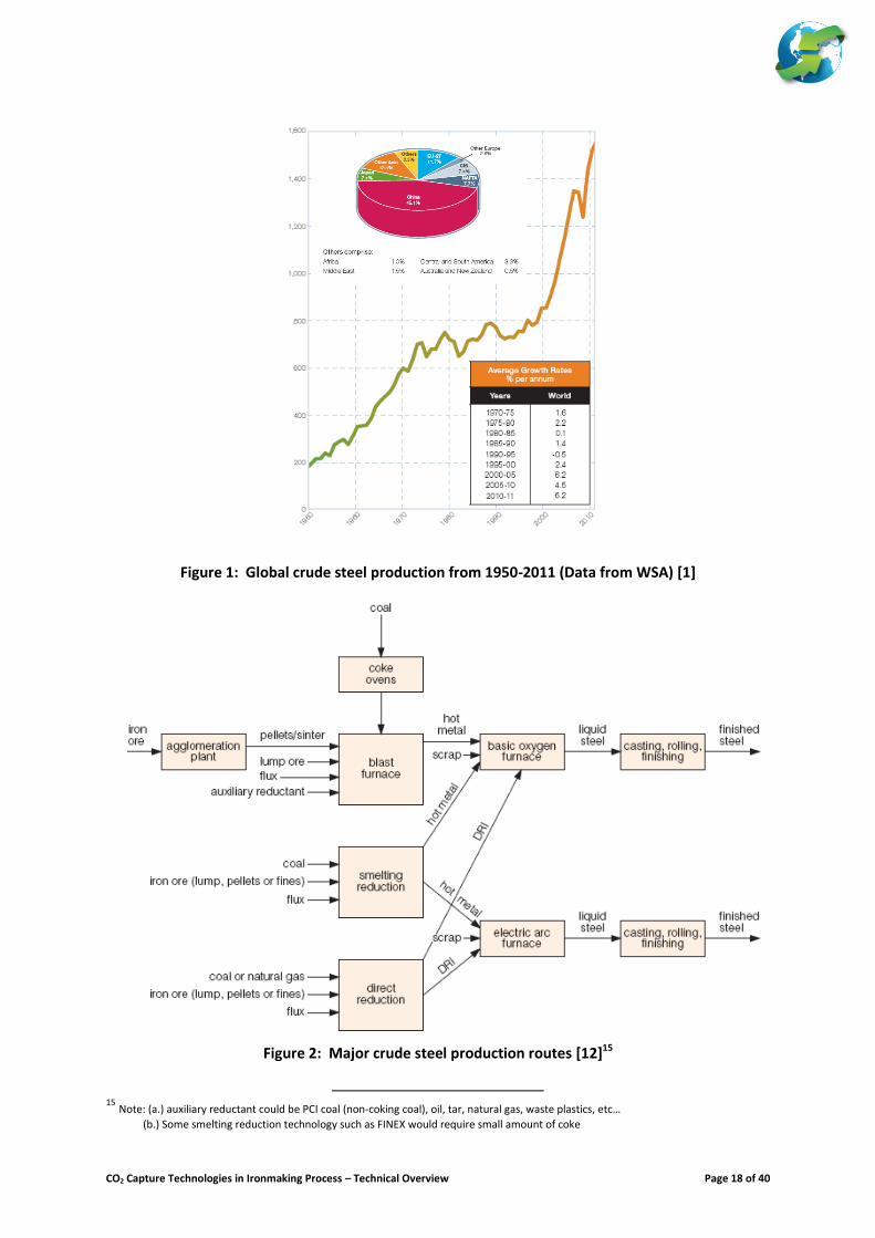
This document is drafted by IEA Greenhouse Gas R&D Programme in support of the activities of the EU Zero Emissions Platforms (ZEP) assessment of potential CCS deployment in the energy intensive industries. It aims to provide an overview of the current state of the art in steel production worldwide and present a brief overview of the development of different technology options for CO2 capture in the steel industry. Steel is the largest globally traded metal. In 2011, around 1.49 billion tonnes of crude steel were produced worldwide; of which ~45% was from China. Other leading steel producing regions or countries include the EU27 (12%), NAFTA
1 (8%), CIS
2 (8%), Japan (7%), and India (5%). Figure 1 presents the historical data showing
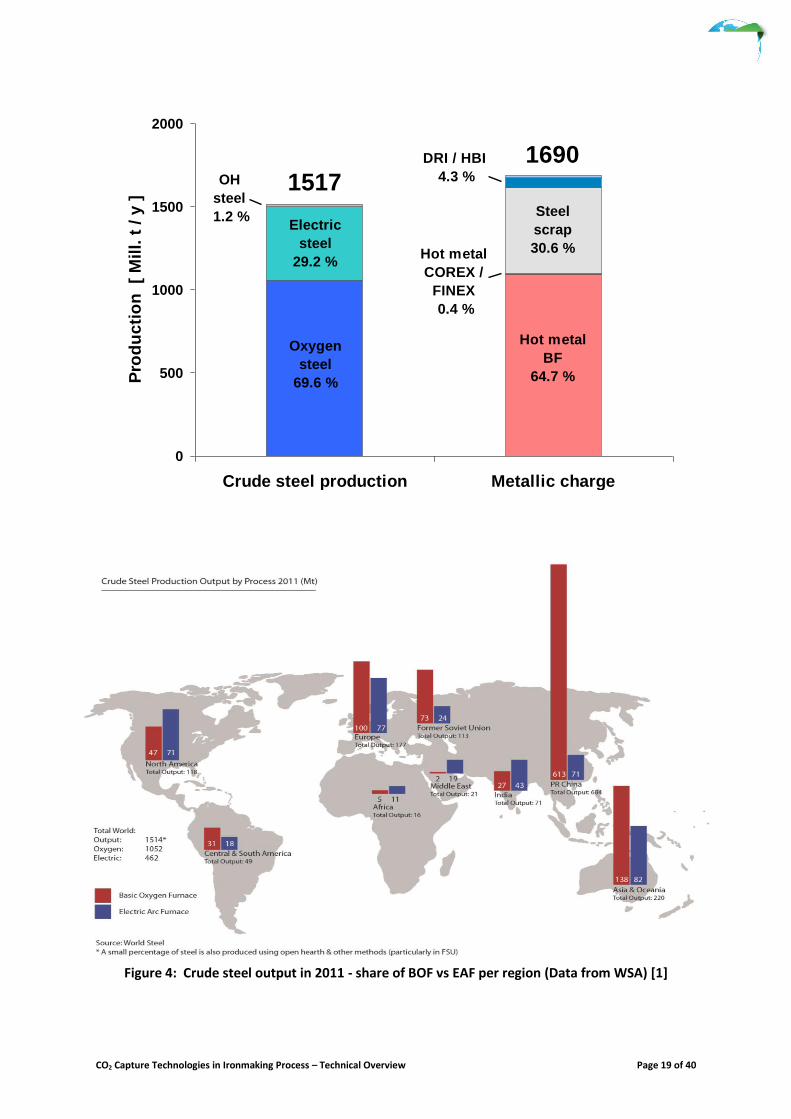
the crude steel production worldwide. In the last decade, steel production has achieved an average annual growth rate of around 5-6% [1] In principle, steel is produced either from virgin ore or from scrap. Currently, there are three leading groups of technologies that produce steel from virgin ore. These include: (a.) Blast Furnace – Basic Oxygen Furnace (BF-BOF) route, (b.) Smelting Reduction – Basic Oxygen Furnace (SR-BOF) route, and (c.) Direct Reduction – Electric Arc Furnace (DRI-EAF) route. The electric arc furnace (EAF) is the only leading technology that produces crude steel from scrap; and the use of the induction furnace is unique to the Indian steel industry. Figure 2 illustrates the different routes on how crude steel are produced. In 2011, around 69% of crude steel was produced from BOF and roughly 29% was produced from EAF
3. Figure
3 presents the share of BOF and EAF in global steel production and the share of the metallic charge required to produce the crude steel. Figure 4 presents the share of BOF and EAF in various regions of the world.
CURRENT STATE OF TECHNOLOGY FOR IRONMAKING PROCESS
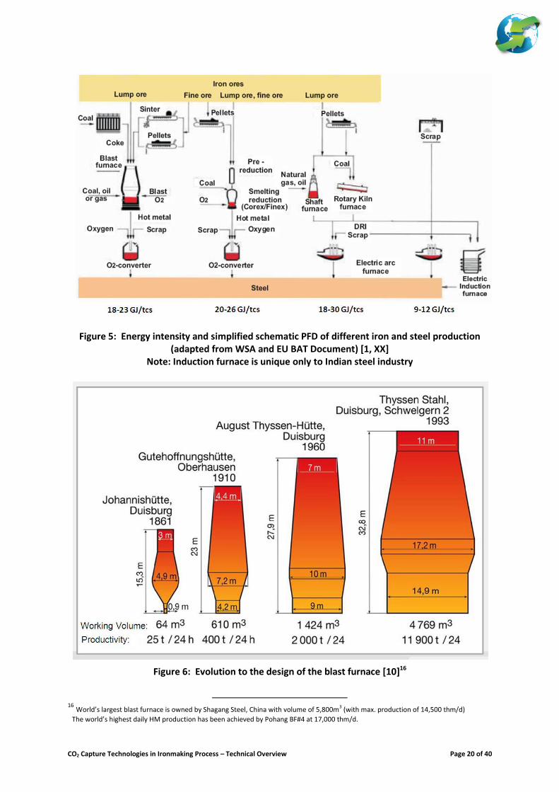
Production of iron from virgin ores requires energy, reductants, and fluxes to produce liquid hot metal (i.e. Blast Furnace and Smelting Reduction) or solid sponge iron/DRI (i.e. Direct Reduction). The iron making process is the most carbon intensive, and could be responsible for nearly 70-80% of the overall carbon input per tonne of crude steel produced from virgin ore
4. Figure 5 presents a simplified schematic diagram
representing the material flow of the three iron making processes and their energy intensity. This section briefly describes the current state of the technology and technical challenges to the operation of conventional blast furnace and other alternative ironmaking processes. Blast Furnace [2-11]
The operation of the blast furnace to produce liquid iron or hot metal would require an agglomerating plant to process the fine ores needed to produce sinter or pellet; some lump ore can be added directly into the furnace. The coke production plant is essential to ironmaking to process the coking coal to produce coke. In the production of the hot metal, the coke has three primary duties namely: (a.) as energy source; (b.) as reducing agent; and (c.) has a mechanical duty to carry the top burden of the furnace. Fluxes are added to the blast furnace to form low melting slag and to separate the impurities present in the ore and the coke.
1 NAFTA is the North American Free Trade Agreement which comprises: USA, Canada and Mexico 2 CIS is the Commonwealth of Independent States which is a regional organization whose participating countries are former Soviet
Republics, formed during the breakup of the Soviet Union. 3 A small fraction of crude steel produced is based on open hearth furnace which is an obsolete technology. 4 Although the iron making process is responsible for most of the CO2 emissions, but it should be noted that the point of emissions are the
users of the off-gases within the steel mill.
CO2 Capture Technologies in Ironmaking Process – Technical Overview Page 2 of 40
Compressed air (cold blast) is generally preheated in the hot stoves and enriched with oxygen to produce the hot blast that is fed into the tuyeres of the furnace. Auxiliary fuels such as PCI coal, natural gas, tar or oil are also introduced into the tuyeres to replace part of the coke as energy input. Top gas (also known blast furnace gas or BFG) produced from the furnace is cleaned primarily to remove dust and particulates. Some of this gas is used as fuel to the hot stoves and the rest is exported to the gas network of the steel mill as by-product fuel or off-gases. The hot metal is tapped out from the bottom of the blast furnace into a torpedo car on a regular interval. This is then delivered to the melt shop. Likewise, liquid slag is also tapped out from the furnace and delivered to the slag granulation plant. Some larger blast furnaces are typically equipped with a Top Recycle Turbine (TRT) to produce electricity from the raw BFG; which is usually exported to the electrical grid of the steel mill. Production of hot metal using coke based blast furnace technology has more than 300 years of technological development
5. Figure 6 represents the evolution of the development of this technology. Over the years, the
performance of the blast furnaces have improved significantly; with the consumption of the reductant nearly reaching its theoretical limit. Figure 7 illustrates the improvement to the blast furnace with respect to the use of the reductant. The current state of art blast furnaces (i.e. global benchmark) is expected to have a specific productivity value in the range of 2.5 to 3.5 thm/m
3/d. The major trends in the improvement of the current or future fleet of
blast furnaces will focus on the following areas of activities:
Facility modernization, which includes building of larger furnaces or upgrading existing furnaces to achieve high productivity and to reduce the consumption of fuel and reductant,
Improvement in raw materials management, and
Extension of campaign life For new build blast furnaces, the current trend is to incorporate technologies that will achieve high productivity and lower fuel rates. Some of these include deployment of technologies such as high temperature stoves, furnacse with capabilities for higher blast enrichment (fuel, oxygen), better burden preparation to provide high quality raw materials, better burden distribution equipment, and enhanced charging and casting capabilities. Scaling up and building of ever larger blast furnaces has been continuous over the past century. However, the scaling up of the current largest blast furnaces seems to have reached its peak. The largest furnaces (i.e. with volume greater than 5500m
3) have been built recently in China, South Korea, Germany, Japan and CIS. These
large furnaces suffer from some limitations including , limited flexibility in adjusting to the hot metal demand and increased raw materials quality requirements (especially coke). These are the main reasons why there will be no new furnaces to be built larger than the current largest BF in world
6.
For the current fleet of blast furnaces, the majority of the future retrofits will involve better raw material management that would result in lower fuel rates and higher productivity; upgrading of facilities to provide better material and energy efficiency and longer campaign life, and should also include the refitting of the casting capabilities to accommodate higher levels of production. In principle, good burden preparation could provide significant gains in material and energy efficiency. Although the blast furnace is known to have the flexibility in handling ores with Iron (Fe) content as low as 50%; nonetheless, the current trend is to use ore with higher Fe content and lower gangue
7. Selection of
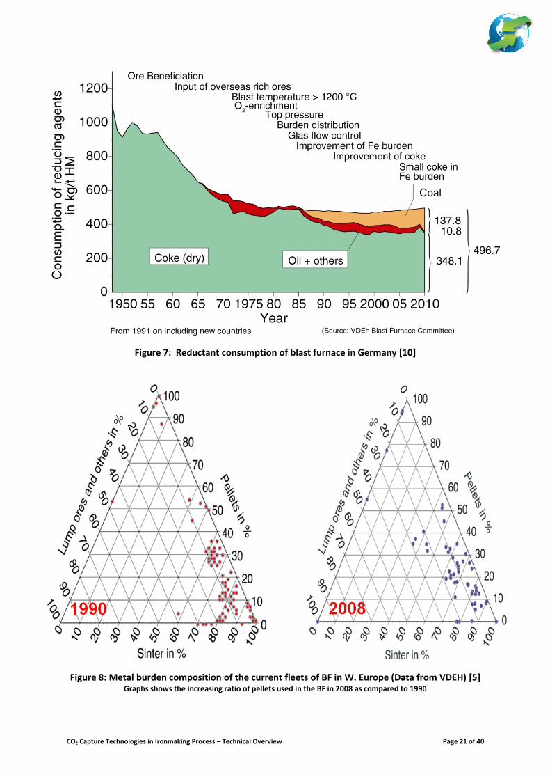
coking coal will favour coal with lower ash and sulphur contents; and the use of fluxed pellets could become a common practice as this also contributes to better burden distribution and gas throughput in the BF. These practices will generally provide better productivity and lower fuel rates. A case in point, the use of pellets with
5 The first known coke based blast furnace producing 2thm/d is situated at Coalbrookdale, UK (1709). Today’s large blast furnace could
reach a production level of 15,000 thm/d. Pohang BF#4 holds the current record of hot metal production at 17,000 thm/d. 6 List of largest BFs in the world: Shagang Steel (Zhangziagang BF at 5800m3), Nippon Steel (Oita 2xBF at 5775m3), Posco (Pohang BF4 at
5600m3), Severstal (Cherepovets BF at 5580m3), Nippon Steel (Kimitsu BF at 5555m3), TKS (Schwelgern BF at 5513m3), Jintang Steel (Caofeidian 2xBF each at 5500m3), Posco (Gwangyang BF4 at 5500m3), JFE Steel (Fukuyama BF at 5500m3).
7 In mining, gangue is the commercially worthless material that surrounds, or is closely mixed with, a wanted mineral in an ore deposit. It is thus distinct from overburden, which is the waste rock or materials overlying an ore or mineral body that are displaced during mining without being processed.
CO2 Capture Technologies in Ironmaking Process – Technical Overview Page 3 of 40
better chemical, physical and mechanical properties have played an important role in several Scandinavian steel mills in achieving high BF productivity. The increasing importance of the use of pellets could also be noticed in the wide variation of ferrous burden composition of the blast furnaces used in Europe between 1990 and 2008 (as shown in Figure 8). This figure shows that the share of sinter used in the blast furnace has decreased over the past 20 years and the growth in the use of pellets and other burden materials could be noted
8.
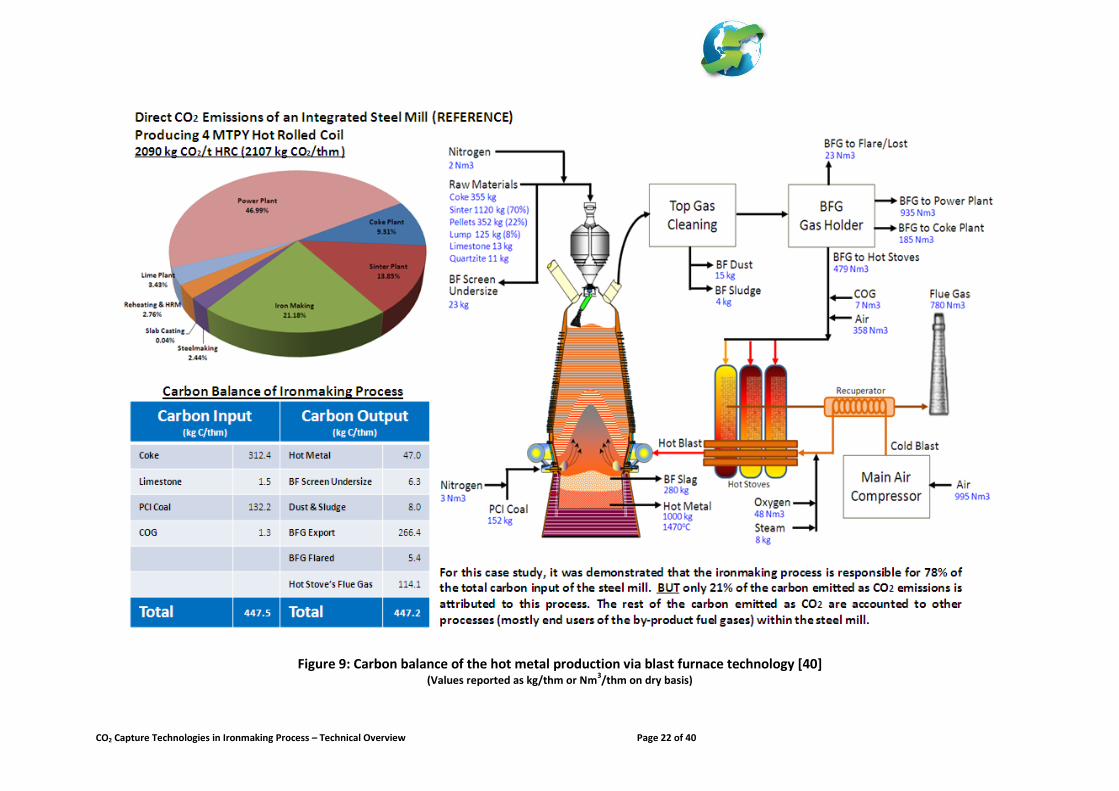
Higher levels of coal, natural gas, tar, or oil injection could reduce coke rate. Waste plastics as auxiliary injectant have been tested in various BF’s in Japan. The current BF fitted with coal injection facilities has the capability to inject between 100 to 150 kg PCI coal/thm. Future BF’s could be designed to have higher rate of coal injection of around 200-250 kg/thm. It could be expected that this will be coupled with higher oxygen injection. In North America where cheap natural gas (NG) is available, it is expected that small to medium BF’s could easily incorporate NG injection to reduce coke consumption with no considerable operational issues. For larger BF, this will be a challenge as NG injection tends to depress the raceway adiabatic flame temperature. Campaign life for a BF is defined by the first blowing-in of the furnace until its blow-out in time for refractory relining and hearth replacement. Once the blast furnace is lighted, it operates for 24h/d and 365d/y non-stop. The typical cycle of a BF campaign could range between 10 to 20 years. Extending the campaign life could be beneficial to the operator as this could reduce CAPEX and increase availability. BF hearth life is the most critical link to the total campaign life of the furnace. Several techniques have been developed to extend the campaign life of the BF; some of these techniques include: (a.) introduction of enhanced cooling and refractory system, (b.) remote refractory repair techniques, (c.) design for longer hearth life, and (d.) techniques to maintain stable furnace operation. Figure 9 illustrates an example of the carbon balance of the ironmaking process of an integrated steel mill producing ~4 million tonnes of hot metal in 2 trains of blast furnaces (Santos, 2013). It could be demonstrated that the blast furnace operation is responsible for ~78% of the total carbon input per tonne of crude steel produced. In spite of this, direct emissions from the hot metal production are only related to the flue gas of the hot stoves and the flaring of some BFG. Totally, this is equivalent to ~21% of overall direct CO2 emissions per tonne steel produced. The export of the BFG will mean that the carbon in this gas will be emitted as CO2 when burned by the users of this by-product fuel gas (i.e. steam boiler of the power plant and underfire heaters of the coke batteries, and this is equivalent to ~46% of the total CO2 emissions). On the other hand, the majority of the carbon in the hot metal will eventually be emitted by the steelmaking process producing the basic oxygen furnace (BOF) gas; and ultimately, most of carbon in the BOFG will be emitted as CO2 by the power plant - being the end-user of this off-gas produced by the converter. Alternative Ironmaking Process [11-30]
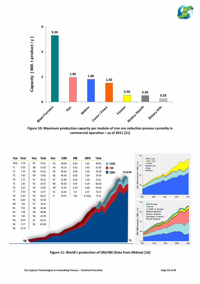
Development of alternative ironmaking processes is primarily driven by a target not to use coke in ironmaking process; and recently this driver has shifted to address environmental concerns to reduce pollutants (primarily from coke oven and sinter plants) and GHG emissions. Currently, there are two classes of alternative ironmaking processes being developed, namely: (a.) direct iron reduction process (DR) producing solid sponge iron or DRI; and (b.) smelting reduction process (SR) producing hot metal or pig iron. Over the past 50 years there are more than 73 direct reduction and 59 smelting reduction technologies developed and tested. Despite of these developments, only limited success have been achieved. For direct reduction technology, only 2 gas based DR technologies using shaft reactors reached successful medium scale commercial operation (i.e. Midrex and HYL/Energiron). All coal based DR technologies only reached pilot or small scale commercial applications (i.e. SL/RN, RHF, etc…). On the other hand, for smelting reduction, only 2 technologies (i.e. COREX and FINEX) have reached medium scale commercial operation. Figure 10 shows the maximum capacity per module of direct and smelting reduction processes currently in commercial operation today. The current largest BF module can produce up to 5.3 MTPY HM per furnace. For gas based shaft furnace reduction processes, i.e. Midrex and HYL/Energiron, has the capacity to produce up to
8 Between 1990 and 2008, the sinter to hot metal ratio of the different BFs in EU15 has decreased from 1.20 to 1.05 [4]
CO2 Capture Technologies in Ironmaking Process – Technical Overview Page 4 of 40
1.9 MTPY DRI per module. On the other hand, COREX and FINEX smelting reduction plants has the capacity to deliver up to 1.5 MTPY HM per module. Nucor and Jindal Steel are currently constructing the largest module for HYL/Energiron with a design capacity of at least 2.5 MTPY DRI at Louisiana (USA), and Angul/Raigarh (India)
9 respectively. Both sites will also be equipped with capture of CO2 from the reactor’s top gas. Posco is
building their third FINEX plant which is designed for 2.0 MPTY HM production at their Pohang works. Unfortunately, all COREX-3000 units (producing 1.5 MTPY HM per module) in Shanghai are now being dismantled and transferred to Xinjiang; where the first rebuilt COREX-3000 unit is planned to start its operation by 2014. a.) Direct Reduction
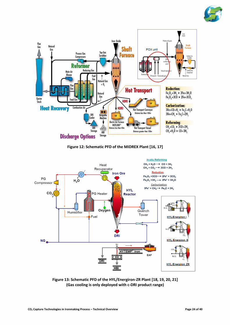
In 2011, around 73 million tonnes of DRI and HBI are produced worldwide (See Figure 11). DRI production is dominant in Middle East, Latin America and Asia. The leading DRI producing countries are India, Venezuela, Iran and Mexico. In W. Europe, there is only one site in Germany that produces steel via DRI route. Gas based DRI production is the most dominant production route. This is led by Midrex (60%) then followed by HYL/Energiron (15%). These units are generally situated in regions where cheap natural gas is available. The majority of the coal based DRI production is located in India. SL/RN Rotary Kiln with Rotary Cooler is one of the leading technologies. Currently, there are 22 SL/RN units commercially operated in India. Several other rotary kilns, designed and developed indigenously, are also operating commercially. This includes kilns developed in-house by TISCO, OSIL, MECON and Jindal. Typically, these kilns have a production capacity ranging between 0.10 – 0.15 MTPY. For this paper, only Midrex and HYL/Energiron technologies will be reviewed. Figures 12 and 13 present the simplified schematic process flow diagrams of both Midrex and HYL/Energiron
10. Both processes are very well
established. Both Midrex and HYL/Energiron use shaft reactors where the ore is reduced using syngas produced from a reformer. Very recently, Energiron has introduced a reformerless version called HYL/Energiron ZR (zero reformer). For both Midrex and HYL/Energiron technologies, either lump ore, or pellets specially prepared for direct reduction ironmaking, are charged as raw material into the top of a shaft furnace. The ore is reduced inside the furnace using syngas from a reformer and the reduced iron is discharged from the bottom of the furnace. Both technologies provide various discharge options. Product could be discharged as: (a.) cold DRI (where cooling gas is used to cool down and carburised the DRI to ambient temperature and stored); (b.) hot DRI (where DRI are directly charged into EAF at around 500
oC to 700
oC); or (c.) HBI (where hot DRI at 700
oC is
charged into a briquetting machine); Syngas used to reduce the iron ore is generally produced from a reformer. But other sources of reducing gas (i.e. syngas from coal gasification, coke oven gas, COREX export gas, etc…) could also be used. Midrex uses their own design autothermal catalytic reformer, where natural gas is heated to 900
oC to convert
~90-92% of the NG to syngas which is predominantly CO and H2. The reformer is heated using fired tubular heat exchangers (containing the catalyst) housed in a furnace fuelled partly by the top gas from the shaft and NG. Very recently, Midrex has also introduced a small Partial Oxidation (POX) module by introducing natural gas and oxygen to boost the syngas with more CO and H2 and increase syngas temperature to ~1000
oC.
For Energiron III (HYL III), syngas is produced from a steam methane reformer (SMR) where NG is converted to syngas containing very high hydrogen content (i.e. >80%); and this syngas is introduced to the shaft at higher operating pressure (i.e. 5 to 8 Bar). Additionally, CO2 in the recycled top gas from the shaft is removed prior to mixing with the syngas from the reformer, and oxygen is added to increase temperature of the syngas via partial oxidation reaction. On the other hand, HYL/Energiron ZR produces syngas in the shaft reactor using partial oxidation of compressed preheated natural gas. Natural gas is compressed prior to mixing with the recycled top gas from the shaft; and the resulting gas mixture is humidified and preheated prior to its introduction into shaft together with oxygen.
9 The two sites owned by Jindal S&P will be based on 4 modules of HYL/Energiron ZR using syngas from coal gasification. 10 Technology owner of Midrex is Kobe Steel. Siemens VAI also build Midrex under licence agreement. Owner of HYL/Energiron is Tenova
which is a joint venture between HYL, Technint and Danieli.
CO2 Capture Technologies in Ironmaking Process – Technical Overview Page 5 of 40
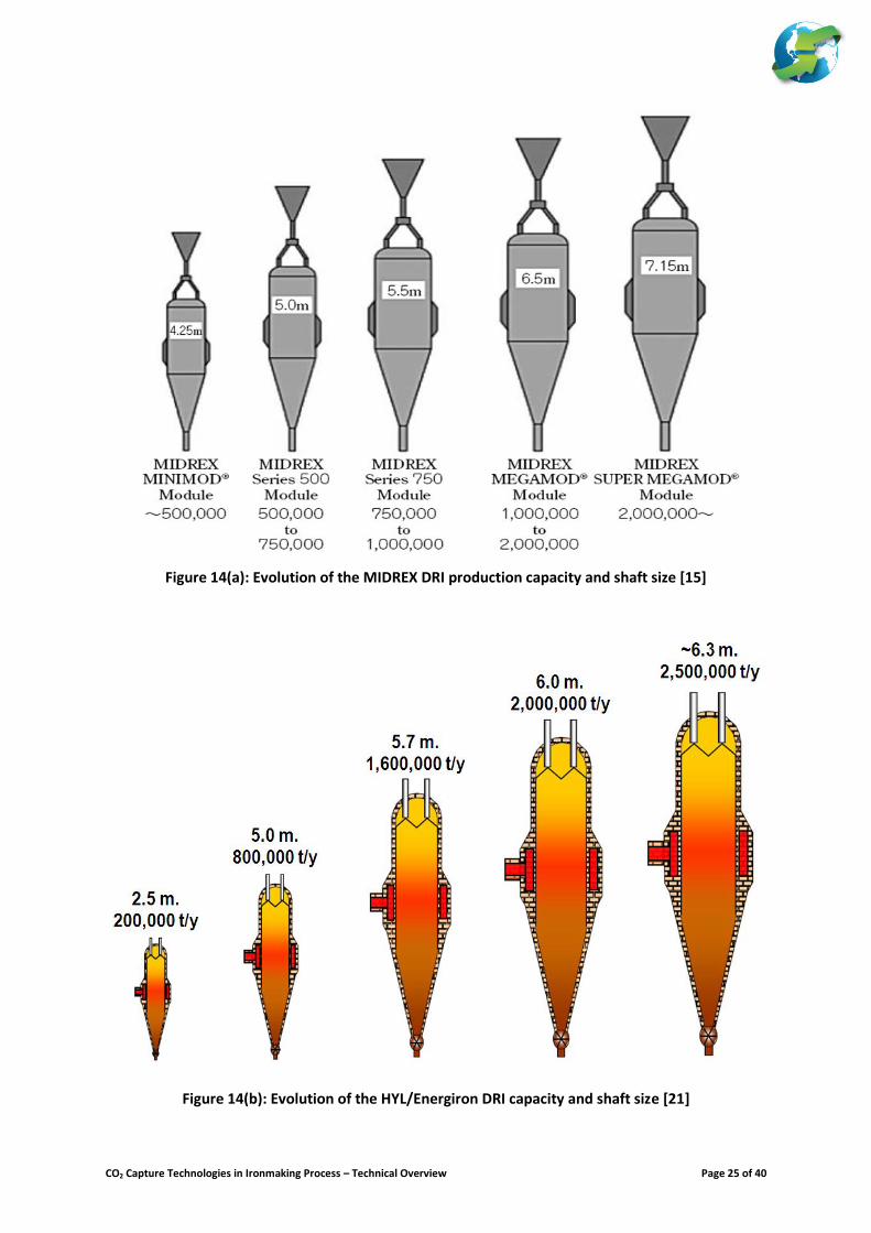
Another important feature of both Midrex HYL/Energiron is the option to use NG in the cooling of DRI at the bottom of shaft reactor to increase the degree of carburisation of the DRI (i.e. higher carbon content of DRI provides lower electrical and electrode consumption to the EAF). Development of both shaft reactor technologies by Midrex and HYL/Energiron started in late 1950’s. Figure 14 presents the evolution of production capacity and shaft size of both Midrex and HYL/Energiron. Some of the current challenges and future trends in gas based DRI plant could be summarised below:
The economics of the gas based DRI technology is highly dependent on natural gas price.
The technology is originally developed based on the use of lump ore. Since supply of good quality lump ore is limited, thus the increase use of pellets specifically designed (i.e. use of pellets coated with lime hydrates) for DRI operation is the trend for the future.
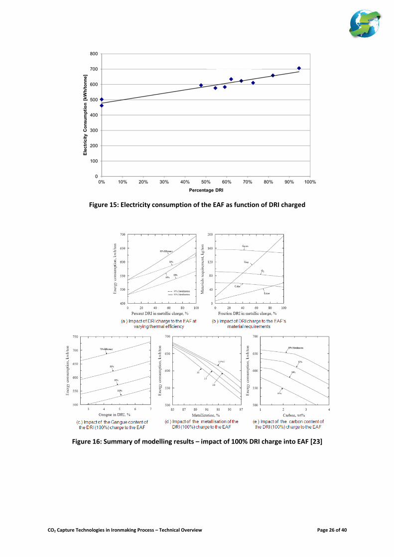
Development and improvement to the use of DRI/HBI in EAF is on-going. Current plant experiences have indicated an increase in electrical and electrode consumptions when the share of the DRI as the metal burden input to the EAF is greater than 50% (as shown in Figure 15). The increase of energy consumption is generally due to the handling of gangue by the EAF. Figure 16 illustrates some of the possible impact of the quality of the DRI to the energy consumption of the EAF.
To reduce energy consumption in EAF, future development will focus on how to improve the quality of DRI produced. The main parameters impacting EAF energy use are composition of raw materials (%gangue and chemistry, metallization, %C, %P, energy content), operating practices (power profiles, foamy slag and melting practices) and furnace design (heel, O2 use and tools, OGS, charging system, AC/DC). A case in point, the new NUCOR plant being built is designed to produce DRI that could achieve 96% metallisation and high level of carburisation.
Hot charging DRI to the EAF could also provide significant benefits. For example, charging DRI at 600
oC DRI could result to savings of 100 to 150 kWh/tls has been reported. Hot charging could also
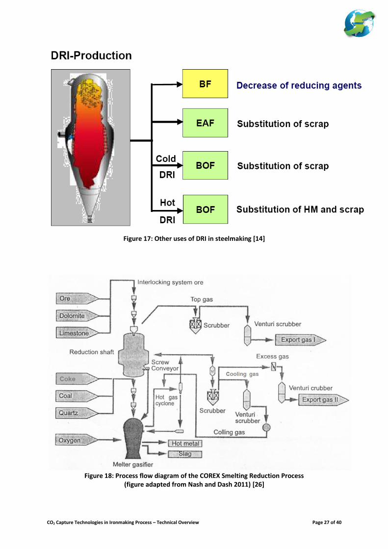
give the benefit of a reduction in DRI’s FeO content versus their normal HBI production. The other uses of DRI/HBI are summarised in Figure 17. It should be noted that the use of DRI/HBI could be complimentary to the operation of BF/BOF steel production. AK Steel has used HBI to increase productivity to their blast furnace since the early 1990’s. Their experience showed that a 30% HBI charge and natural gas injection to their blast furnace has resulted to reduced coke consumption down to ~440 kg/thm [2] The total CO2 emissions per tonne of crude steel produced from DRI does vary significantly depending on several factors (this could range between 1000 to 1500 kg CO2/tonne crude steel – tcs). Considering only the pellet and DRI production facilities (including electricity consumption), reported values for the total CO2 emission could vary between 600 and 800 kg/tcs. This is dependent on the technology used (i.e. with or without reformer; with or without sale of CO2; amount of O2 consumption; etc…). To include the equivalent CO2 emissions from the EAF steelmaking (assuming 100% DRI charge) due to the electricity and oxygen consumption, this could add to about 350 to 650 kg/tcs to the total CO2 emissions (assuming electricity is carrying 0.75 kg CO2/kWh). The variation could be dependent on the quality of the DRI (% metallisation and carburisation, % gangue, etc…) and technology selection (i.e. cold charging or hot charging).
b.) Smelting Reduction
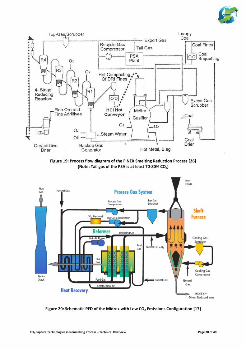
In 2011, hot metal produced from smelting reduction technologies (i.e. COREX and FINEX) only accounted for ~6.8 million tonnes. India is currently the dominant producers of hot metal from COREX. Only South Korea produces hot metal from FINEX. The basic principle of smelting reduction is splitting the blast furnace process into two vessels therefore eliminating the cohesive zone. Only the COREX and FINEX technology has reached industrial/medium-sized scale commercial operation. This paper will only present an overview to these two processes. The primary driver to develop smelting technologies is to reduce the use of coke in ironmaking process. FINEX is also developed to take advantage of the use of cheap fine ores which serve as an additional driver to its development. Figures 18 and 19 present the schematic process flow diagram of COREX and FINEX respectively.
CO2 Capture Technologies in Ironmaking Process – Technical Overview Page 6 of 40
A typical COREX ironmaking plant consists of a reduction shaft, smelter/gasifier and gas handling plant. This involves the use of lump ore or pellets as metal burden feed, non-coking coal and a small amount of coke (around 30-60 kg/thm). By-product fuel gas produced from smelter/gasifier is used as reducing gas to the shaft reactor and any surplus gas are exported to the gas network of the steel mill. These gases are considered medium LHV consisting of CO2, CO and H2. Currently, any surplus off-gases produced are used as fuel for power plant and other users. Very recently, this is also used as reducing gas for a gas-based DRI plant (i.e. JSW Steel in India). COREX comes in three different sizes (i.e. COREX C-1000 with capacity of 0.30 to 0.45 MPTY, C-2000 with capacity of 0.60 to 0.80 MPTY, and C-3000 with capacity of 1.5 MPTY). COREX C-1000 and C-2000 are commercially proven to be reliable based on past and present operating experiences in countries such as South Africa, South Korea and India. On the other hand, scaling up to COREX C-3000 was problematic and would require further development as experienced in China. FINEX is an evolution from COREX and FIOR developed by a consortium consisting of Siemens VAI, Posco and RIST. This involved the use of fine ore pre-reduced in a series of fluidized bed reactors by using reducing gas generated by the smelter/gasifier. The reducing gas is generally processed to remove CO2 prior to its recycle into the fluidized bed reactors. The smelter/gasifier where the directly reduced iron would be melted would require non-coking coal and some amount of coke (around 100-120 kg/thm). There are two operating FINEX plant in South Korea with a capacity of 0.6 MPTY and 1.5 MPTY. The FINEX with capacity of 2MTPY is currently being built. This technology is said to be exclusive for used by POSCO only.
OVERVIEW TO THE DEVELOPMENT OF CO2 CAPTURE TECHNOLOGIES IN IRON AND STEEL PRODUCTION
Avoiding at least 50% CO2 emissions from steel production would require sweeping changes to the operation of the ironmaking process. It could be noted that CO2 emissions reduction via efficiency gains could only achieve up to 15-20% reduction. Only the capture of CO2 could drastically reduce emissions from the iron and steel production. Furthermore, it should be noted that the role of the availability of scrap would also play a part in the dynamics of CCS deployment. Currently, only FINEX and HYL/Energiron
11 do have options to capture CO2 without any significant changes to
their processes. However, the capture of the CO2 from these processes using today’s configuration could only reduce specific CO2 emissions per tonne of crude steel by around 25 to 35%
12 (This estimate include the DR-
EAF or FINEX-BOF facilities – including oxygen production and small coke plant for FINEX; and electricity carrying 0.75 kg CO2/kWh). Midrex has suggested a process scheme that would allow the capture of CO2 from their DRI production plant. This includes the removal of CO2 from the slips stream of the top gas using PSA and involves changes to the heat recovery equipment to include the pre-heating of the CO2-lean top gas (as shown in Figure 20). For COREX, a back end removal of CO2 from the export gas could be implemented to produce an export gas rich in CO and H2. This should require export gas compression equipment and PSA (These are the same equipment used by FINEX for CO2 capture). To achieve deeper CO2 emission reduction, it would require breakthrough changes to the current operation and practices in ironmaking. This section will only review the three leading steel industry consortiums that develop CCS technology worldwide.
11 Worldwide, there are 5 facilities using HYL/Energiron technology that captures part of the CO2 emission from DRI production and sold it
to the food industry. In planning, Emirate steel (also using HYL/Energiron) is currently upgrading their DRI module to capture CO2 and used this for EOR application. Likewise, NUCOR has also plans to capture CO2 from their HYL/Energiron DRI plant and sell it as feedstock for chemical production or EOR application (given the fact that plant in Louisiana is only ~8 km away from an existing CO2 pipeline).
12 With capture of CO2 from the PSA tail gas, Posco has reported a possible reduction of up to 55% - however, this number should include future improvements to the FINEX operation (i.e. reduction in the oxygen and coke consumption).
CO2 Capture Technologies in Ironmaking Process – Technical Overview Page 7 of 40
Ultra Low CO2 Steelmaking (ULCOS) Programme [31-44]
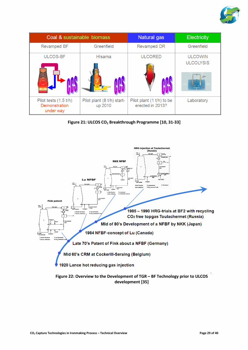
The ULCOS programme is a consortium of European steel and allied industry with an objective to evaluate options for at least 50% reduction of GHG emissions from steel production. Figure 19 presents the different options evaluated under ULCOS. These include the ULCOS BF (TGR BF), HISARNA, ULCORED and ULCOWIN. Three of the processes would require CCS and the last one would require carbon free electricity. a.) Top Gas Recycle Blast Furnace (ULCOS BF)
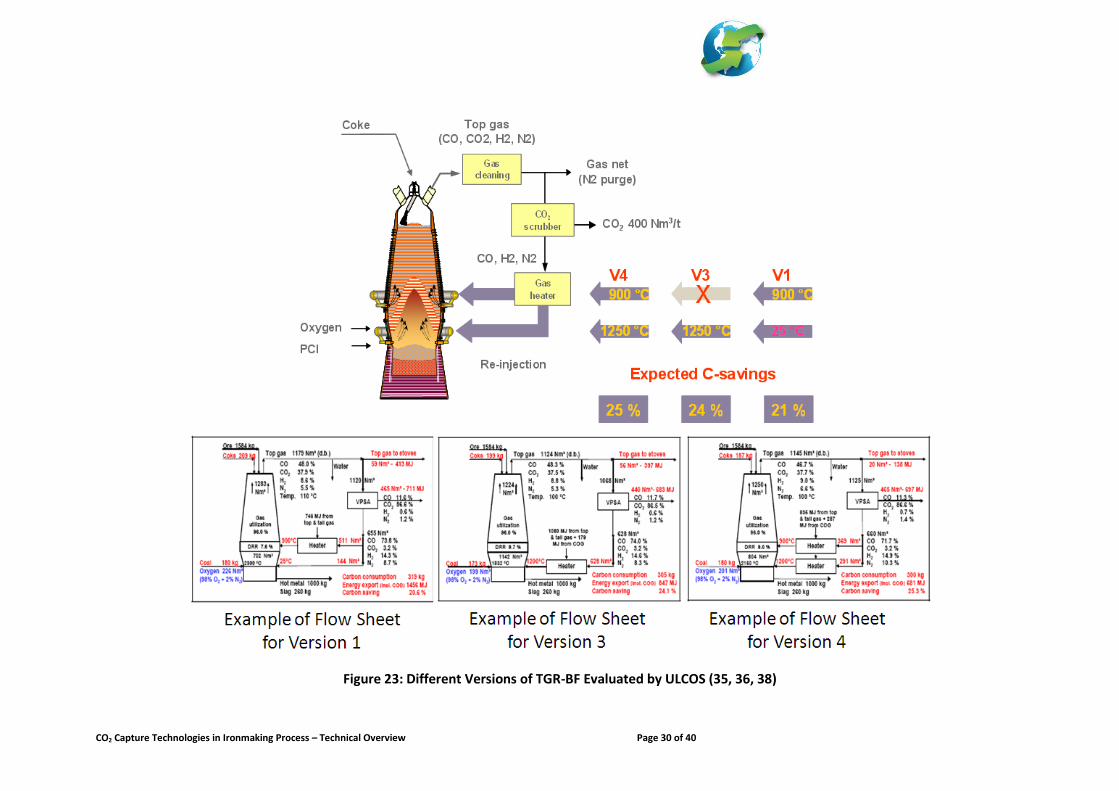
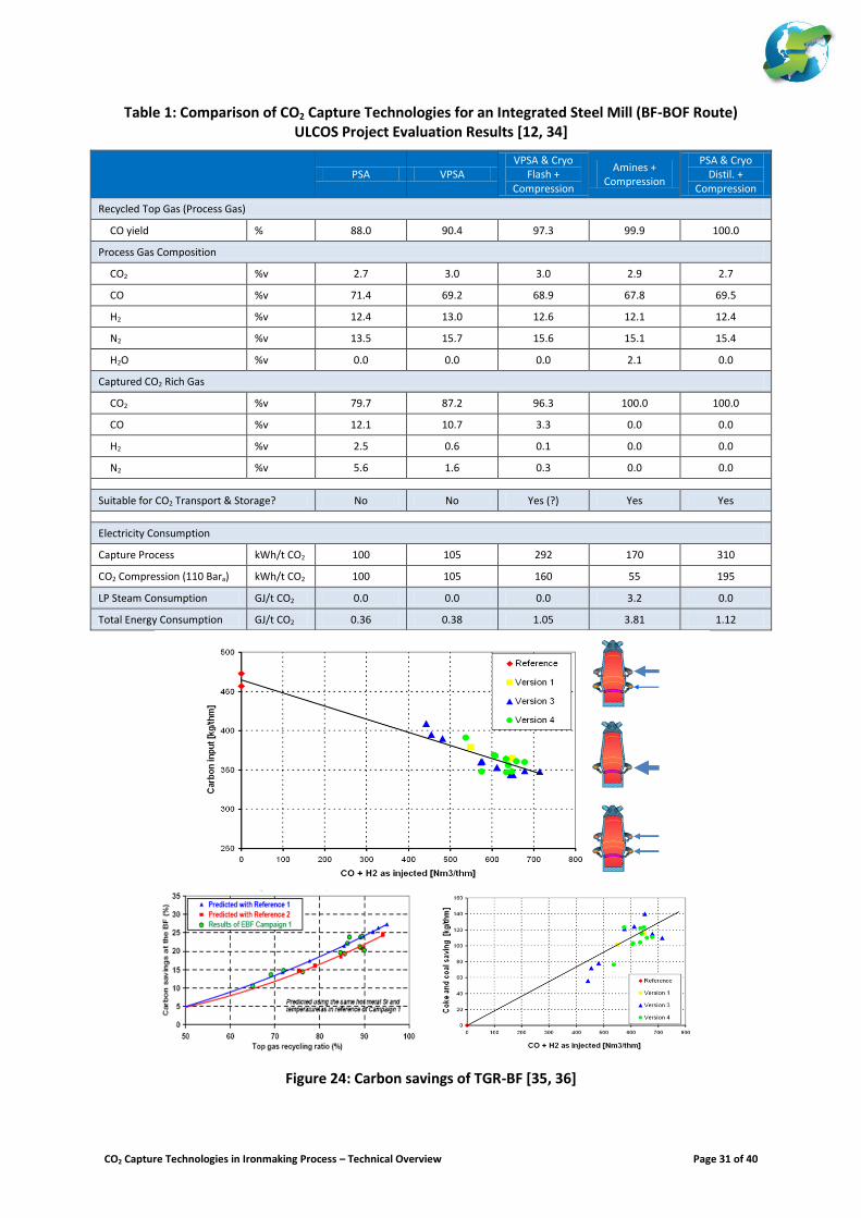
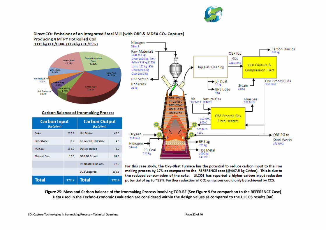
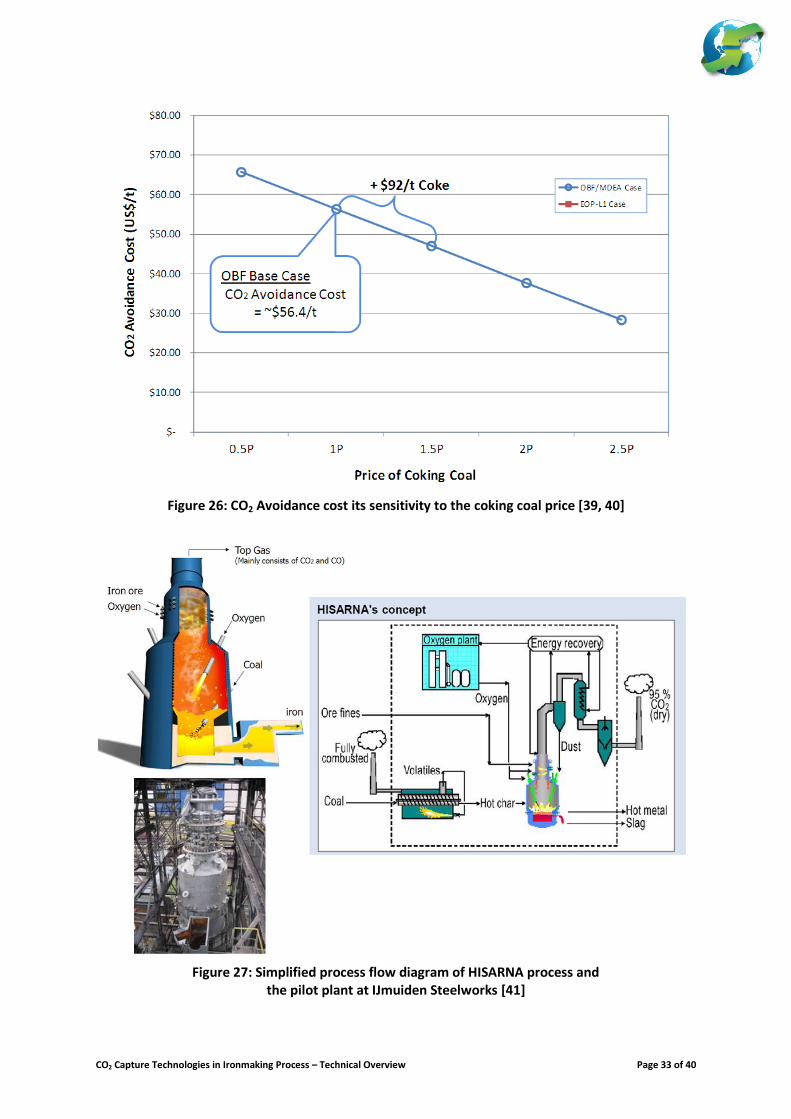
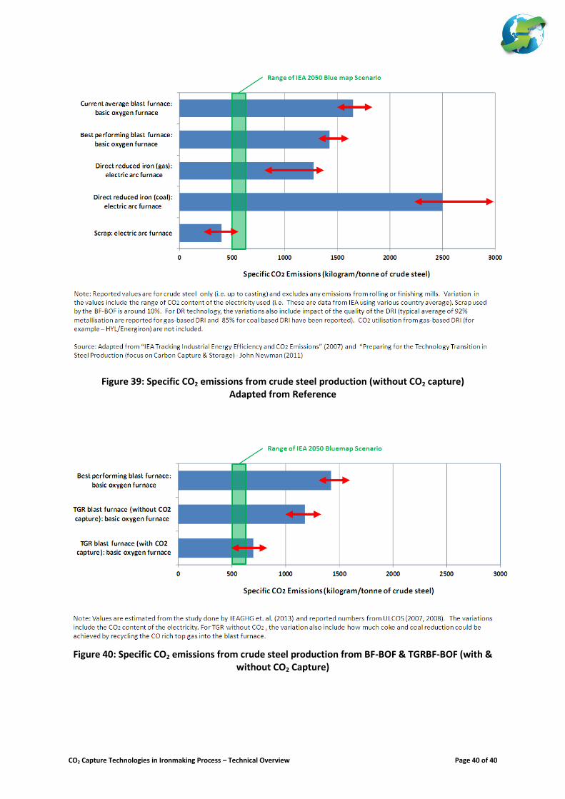
In the literature, “Top Gas Recycle Blast Furnace” (TGR-BF) also known as “Nitrogen Free Blast Furnace” (NFBF), “Oxy-Blast Furnace” (OBF), and this technology is also related to Hot Reducing Gas (HGR) Injection Technology. Figure 21 illustrates the historical development of the TGR-BF. The TGR-BF involves the replacement of hot blast with nearly pure oxygen and recycled top gas with the removal of CO2. This process comes with several versions. ULCOS has developed this technology and evaluated three different versions. This is illustrated in Figure 22. The removal of CO2 from the top gas could be achieved by various options. Table 1 summarises the different CO2 removal options evaluated by the ULCOS programme. In this process, there are two key CO2 emissions reduction mechanisms involved. The process related modification allowed up to 20-25% reduction. This is due to the reduce coke and coal consumption. On the other hand, only CCS could reduce the overall CO2 emissions per tonne of steel produced up to 55-60%. Figure 23 illustrates the carbon saving that could be achieved by the TGR-BF. This has been validated using the LKAB’s EBF facility at Lulea, Sweden. Recently, IEAGHG has led and evaluated the techno-economics of hot rolled coil production equipped with TGR-BF and CO2 capture plant using chemical absorption based on MDEA/Pz solvent. The overall mass and carbon balance of the ironmaking process is presented in Figure 24 (See Figure 9 for comparison to the REFERENCE Case). One of the conclusions of this study demonstrated that the cost of CO2 avoidance is closely linked to the coking coal price as illustrated in Figure 25. Some of the key challenges to the development of TGR-BF include:
Demonstration of TGR-BF in large scale operation is necessary to validate the results obtained from the EBF campaign. Furthermore, the large scale TGR-BF should be able to operate and demonstrate a full cycle of the BF operation (i.e. it should operate at least 10 years to simulate a full campaign life of the blast furnace).
Key to this demonstration is the validation of coke reduction potential of this technology. Critical to this factor is the permeability and mechanical strength of the coke. The EBF campaign has demonstrated that it is possible to reduce the coke rate. Question arises if this is scalable with a larger size blast furnace. The demonstration should be able to validate the scalability of this technology.
Challenges include the design in the modification of the blast furnace. Particular importance is to the handling of the oxygen and the injection of the recycle top gas into the tuyeres and shaft which will require excellent gas penetration and distribution.
Further development is necessary to the design of the process gas heating. This involves the handling of high CO and H2 gas at greater than 900
oC.
b.) HISARNA
HISARNA is a class of smelting reduction technology developed by ULCOS based on the combination of three different technologies namely: Cyclone Converter Furnace (CCF) for ore pre-reduction step, Hismelt for the smelting of the pre-reduced ore, and the use of thermally heated screw for the pyrolysis of coal to produce char that is fed into the smelter. Figure 27 presents a conceptual schematic flow diagram of the HISARNA. The process involves the use of fine ores that are fed into the CCF (top portion of the vessel) where melting and pre-reduction of the ore is achieved (at least 20% pre-reduction of the ore is desired). Oxygen is introduced into the CCF (top of the vessel) to burn any combustible gas to reach the necessary temperature for partial melting of the ore; likewise, oxygen is also introduced into the smelter vessel (i.e. into the freeboard of the smelter vessel just above the plashing slag layer) using lances to post-combust the reducing gas generated from the bath melt (this should provide the heat to the melter). The partially melted ores in the CCF are separated from the gas by means of centrifugal motion (i.e. where the top gas - mainly consists of CO2 and
CO2 Capture Technologies in Ironmaking Process – Technical Overview Page 8 of 40
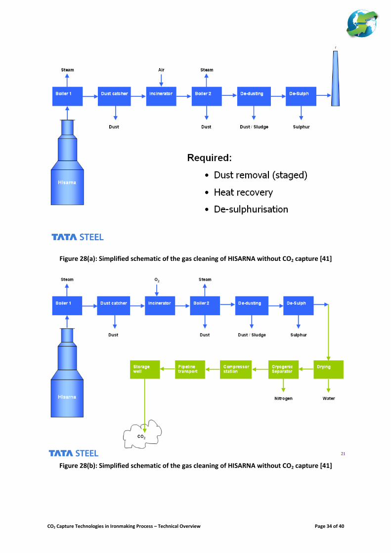
some CO which are separated and flow out to the top of the cyclone; whilst the pre-reduced ores drop into the smelter bath at the bottom of the cyclone). Pyrolysed granular coal (i.e. char) is introduced directly into the bath just around the slag/hot metal interface; the injection of the coal char should introduce a swirling motion where the final reduction step could occur by contacting the pre-reduced ore with carbon. Also, due to the vigorous stirring motion at the slag and hot metal, the resulting slag is expected to have minimal FeO content. The hot metal and slag are continuously withdrawn from the bottom of the smelter vessel. Figure 28 shows the schematic flow diagram of the cleaning of the top gas generated from the HISARNA with CO2 capture. This involves a series of gas cleaning steps which include the dry dust catcher to remove particulates, an incinerator to burn the remaining CO and carried over unburned carbon particulates, a waste heat recovery steam boiler, a scrubber for de-dusting, desulphurisation unit, and gas dehydration unit. The resulting dry clean gas should consist at least 90-95% CO2. The CO2 rich gas is processed in the CO2 processing unit where CO2 is separated via cryogenic separation and compressed prior to its delivery to the pipeline. Currently, a pilot plant at Tata Steel’s IJmuiden works producing 8 thm/d HM is being demonstrated (as shown in Figure 27). ULCOS has recently completed their 2
nd experimental campaign and indicated achieving their
objectives. Results of the 2nd
campaign have not yet been reported in the open literature13
. The 3rd
campaign is scheduled to proceed during the spring/summer of 2013. Some of the key challenges to the development of HISARNA:
The different components of HISARNA have been demonstrated separately in various pilot and industrial facilities. For example, the CCF has been demonstrated at IJmuiden steelwork that processed up to 20 t/h of iron ores during the 1990’s. Industrial scale Hismelt producing 0.6 MTPY HM was demonstrated at Kwinana, Australia. Current experience at the HISARNA pilot showed that integration of the different technologies would require several fine tuning and adjustment.
Key to the success of the current experimental campaign of the pilot plant are: o To achieve the necessary pre-reduction level of the ore at the CCF (at least 20% pre-
reduction is desirable). o To demonstrate the reliability of the oxygen lances and coal injection equipment. o To prove the durability of the refractory and the reliability of the cooling staves design of the
smelter vessel. (Early demonstration of the Hismelt noted the weakness in the refractory of the vessel and modifications have been implemented in the current HISARNA pilot demonstration)
o To gain the experience and lessons to be learned in the operation of the pilot plant that would contribute toward to the design of the hearth of the smelter vessel as this is the key to a reliable operation and long campaign life for future larger scale demonstration of this technology.
The next step will require the scaling up of the current HISARNA pilot plant by 5 times of its current capacity (i.e. from production of 0.06 to 0.3 MPTY HM). The success of the HISARNA pilot plant campaign does not necessary mean success in the scaling up of this technology. Experience and lessons learned from the demonstration and scale up of other smelting technologies should remind us the difficulties in the development of smelting reduction ironmaking process. For example, COREX was first demonstrated in 1982, and the successful medium scale demonstration (i.e. reaching production capacity of 0.8 MPTY HM) was only achieved 20 years after. Experience by Baosteel in the scaling up of COREX to produce 1.5 MPTY HM has not been a complete success.
c.) ULCORED
ULCORED is the development of a shaft based ore reduction process using syngas to produce DRI, and at the same time capturing greater than 50% of the CO2 emitted from the process. Development of this technology includes both gas and coal based DRI production. Most of the development work was undertaken by LKAB, Siemens VAI and Swerea MEFOS. Currently there are plans to install an experimental DR pilot facility producing 1 t/d DRI at Lulea, Sweden.
13 Some of the results of the first experimental campaign have been reported at the 1st IEAGHG Iron and Steel CCS workshop. (IEAGHG,
2011)
CO2 Capture Technologies in Ironmaking Process – Technical Overview Page 9 of 40
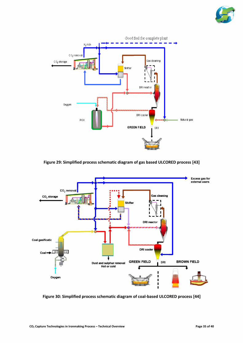
Figures 29 and 30 present the schematic flow diagram of the gas and coal based ULCORED process. For this paper, only the gas based ULCORED will be reviewed. The production of the DRI using gas-based ULCORED involves a shaft reactor fed with lump ore or pellets and uses nearly pure oxygen to burn pre-heated fuel in a partial oxidation reactor (POX) to produce the syngas as the primary reducing gas. The process involves the use of a shift reactor to convert at least 90% of the CO in the cleaned off-gas from the shaft reactor to produce H2 and CO2. The CO2 is then separated using VPSA or PSA (as shown in Figure 28). Most of the top gas from the PSA/VPSA is used as cooling medium of the DRI. This is generally mixed with natural gas to make up the fuel demand of the POX reactor. Some part of the top gas will be preheated in the shift reactor and mixed with the syngas produced by the POX. Finally, a minor part of the gas could be exported to the steelworks as by-product fuel to bleed out the nitrogen content. The design of the shaft reactor to produce the DRI should have similar functions as that described for MIDREX or HYL/Energiron. It is expected that the reducing gas will be introduced in the middle of the shaft. Likewise, hot or cold DRI could be produced. Cooling using natural gas for higher level of decarburisation will be deployed. However, unlike the HYL/Energiron DRI process or Midrex with partial CO2 capture version, the ULCORED uses the shift reactor as the main source of heat to preheat the top gas from the PSA/VPSA (i.e. there will be no steam production process in the shift reactor – as normally seen in any IGCC with CO2 capture) therefore eliminating the fired gas-gas heater (which should eliminate the CO2 emissions from the flue gas of the pre-heater of HYL/Energiron or from the flue gas of the autothermal reformer of Midrex). This therefore results in the capture of nearly all the CO2 emissions of the DR plant. Some of the current development and key challenges of ULCORED are:
Nearly every major component of the gas-based DRI reactor are in commercial operation (shaft reactor, shift reactor, PSA/VPSA and POX). However, integrating these components to produce the DRI and capture the CO2 at the same time would require large scale demonstration to test its availability, reliability and the quality of its products (DRI and CO2).
Development of the pilot plant is an important element to the demonstration of ULCORED. This should provide opportunity to establish and validate the different technical and economic parameters in the integration of the different components of ULCORED.
To reduce investment cost, the scaling up of all the components could be an important element of considerations in the engineering of the ULCORED. For example, the largest operating POX reactor currently operating today using NG is producing ~200,000 Nm
3/h of syngas (This is operated by Linde).
This means that at least two trains of POX reactor are necessary to meet the demand of a single train shaft reactor at today capacity that could produce in the range of 2.0 to 2.5 MTPY of DRI
14.
Like any DRI usage in steel production, the major source of indirect CO2 emissions is the electricity consumption during the melting of the DRI in the EAF. An additional feature of the development of the ULCORED process is the deployment of COMELT technology (an EAF using DC power) developed by Siemens VAI which improve the electricity consumption of melting DRI.
CO2 Ultimate Reduction in Steelmaking Process by Innovative Technology for Cool Earth 2050 (COURSE50) Programme [45-48]
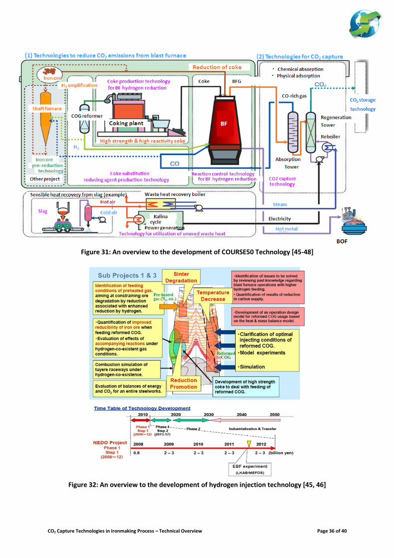
The COURSE50 programme is a consortium of Japanese steel and allied industry funded by NEDO with an objective to evaluate options to reduce GHG emissions from steel production. Figure 31 presents the different technology options evaluated under COURSE50 which include the following:
Technologies that reduces CO2 emissions from the blast furnace (i.e. technologies that reduces coke consumption of the BF)
o Development of hydrogen injection technology to the BF and relevant control systems o Development of pre-reduction shaft reactor using hydrogen as primary reducing agent and
introduction of pre-reduced ore into the BF o Utilisation of CO rich gas from the CO2 capture plant as a reductant for the BF and Pre-
reduction shaft reactor.
14 The calculation of syngas demand is based on the estimate of ~900 Nm3 syngas/t DRI at 92% metallization reported by ULCOS.
CO2 Capture Technologies in Ironmaking Process – Technical Overview Page 10 of 40
Technologies for CO2 capture and storage (i.e. technologies that captures CO2 from the BFG) o Development of chemical absorption technology o Development of physical adsorption technology
Technologies that support COURSE50 Technologies o Improvement to coke ovens to produce coke that is optimum for hydrogen injection o Development of COG reformer to increase its hydrogen content (H2 amplification) o Development of sensible heat recovery from steelmaking slag o Development of Kalina cycle power generation technology o Utilization of Phase Change Materials or PCM o Utilization of heat pumps
This paper will only present an overview to the development of hydrogen injection technology and CO2 capture from BFG using chemical absorption and physical adsorption technologies. a.) Hydrogen injection into the Blast Furnace
Figure 32 presents an overview and the time table of the development of the ironmaking process using hydrogen injection. It is expected that hydrogen from the coke oven gas will be introduced into at the tuyeres level and at the shaft level of the BF. Some of the important considerations of the development of this technology include the improvement to the coke properties that would make hydrogen injection suitable, understanding the gas penetration depth and distribution of the hydrogen into the BF, the impact of hydrogen injection into the BF (i.e. its cooling effect and to the degradation of the sintered ore). Results from the blast furnace inner reaction simulator (BIS) facility that simulates the thermal reserve zone of the blast furnace has been reported in the literature [46, 47] and indicated that an increase reduction rate of the ore by 30-50% at 1050
oC have been achieved.
It should be noted that work has been undertaken at the Experimental Blast Furnace (EBF) at Lulea, Sweden. However, the results have yet to be reported in the open literature. It is important that coke reduction potential using hydrogen as a reductant should be validated in a larger scale operation. It could be noted that work has been undertaken at the Experimental Blast Furnace (EBF) at Lulea, Sweden. Results have yet to be reported in the open literature. It is important that coke reduction potential using hydrogen as reductant should be validated in a larger scale operation. b.) Development of Chemical Absorption Technology for Capture of CO2 from BFG
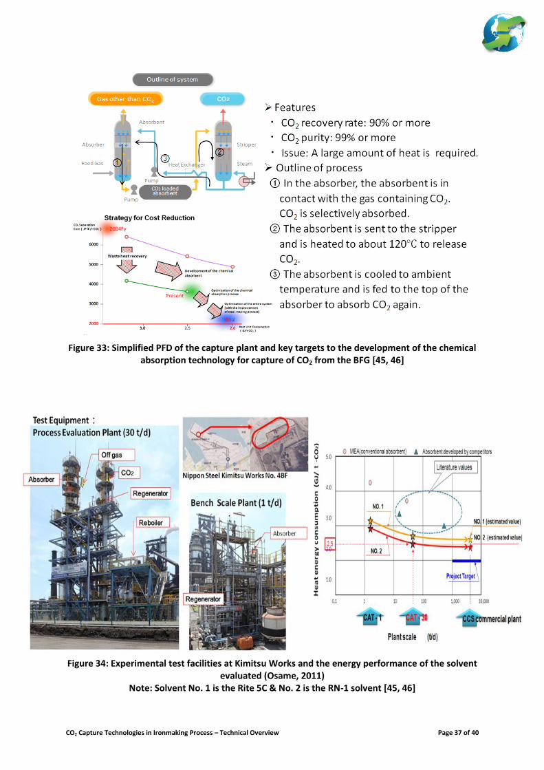
Figure 33 presents the simplified schematic flow diagram of the chemical absorption technology developed for capturing CO2 from the BFG. The primary aim of this technology is to develop solvents that could reduce energy consumption of capturing CO2 down to 2.5 GJ/t CO2; and if to include the optimisation of the CO2 capture plant with additional waste heat recovery integration from the steel work, it was aimed to reduce the overall energy consumption further down to 2.0 GJ/t CO2. A key feature of the development of this technology involves the capture of CO2 from BFG (which is a reducing gas consisting mainly N2, CO2, CO and H2) and usually delivered at pressure between 2 to 4 bar(a). Currently, there are two types of mixtures of amine solvent evaluated in two experimental facilities having a capacity to capture 1t/d and 30t/d of CO2 respectively. These facilities are situated at Nippon Steel’s Kimitsu Works using a slipstream of BFG from BF4 (See Figure 34). Preliminary results have shown that the new solvent developed (RN-1 – based on a single component amine solvent) has achieved the initial target of 2.5 GJ/t CO2 (as shown in Figure 34). It was noted that two other solvents (i.e. involving 2 components amine solvent – RN-2, and a tertiary amine solvent – RN-3) will be evaluated in the near future. Several supporting technologies related to recovery of waste heat and its utilisation is currently being developed as mentioned earlier. It is expected that the utilisation of waste heat within the steelworks and
CO2 Capture Technologies in Ironmaking Process – Technical Overview Page 11 of 40
recovery of heat from slag should contribute significantly toward cost and energy reduction target set by the COURSE50 programme. Furthermore, although not mentioned in the open literature, an important aspect of this development is the utilisation of the CO rich gas as a reductant in the blast furnace. This is planned to be introduced at the tuyeres level together with the hydrogen produced from the coke oven has been briefly mentioned. Coke consumption reduction potential of this CO rich gas should also be validated in larger scale blast furnaces. c.) Development of Physical Adsorption Technology for Capture of CO2 from BFG
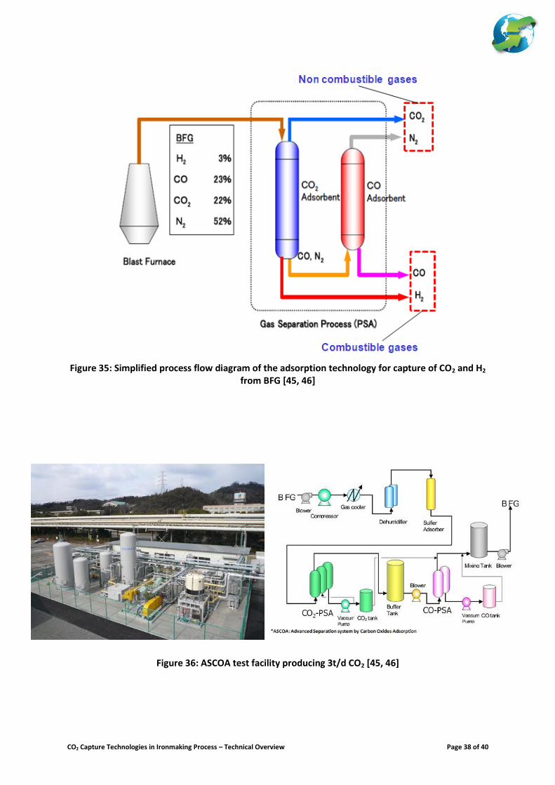
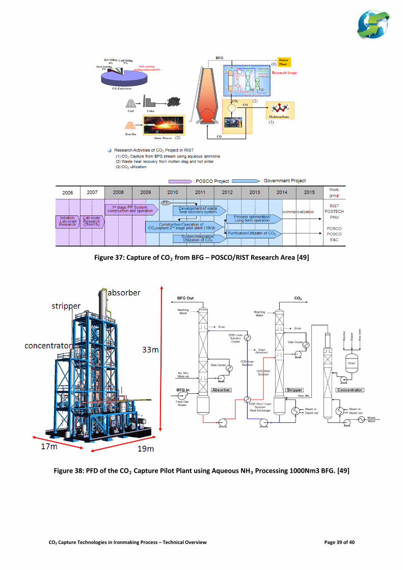
Figure 35 presents the schematic flow diagram of the physical adsorption process developed under COURSE50 separating H2 and CO from the BFG. The technology is based on a two stage PSA separation technology with the 1st stage selectively separate the CO2 and H2 from the BFG, and the 2nd stage selectively separate the CO from the resulting gas from the 1st bed. Bench scale test producing at least 3 t/d CO2 has been performed (as shown in Figure 36). The evaluation has indicated an 80% CO2 capture rate and maximum purity of CO2 of about 99.5% have been achieved. POSCO – RIST CO2 Capture Development Programme [49-50] Development of CCS technology for application in the non-power sector is currently undertaken by a consortium led by POSCO and RIST looking onto a steel industry specific application. The pilot scale demonstration of CO2 capture technology is funded by the Korean Ministry of Knowledge with some contribution from the private sector. Figure 37 presents the main research areas and ideas undertaken by the consortium. The main scope of work includes:
Capture of CO2 from the BFG.
Recovery and utilisation of waste heat within the steelworks
Utilisation of CO2 and CO for other industrial users Only the capture of CO2 from the BFG will be the focus of this review. The development of the CO2 capture technology undertaken by RIST involves the use of aqueous ammonia (with concentration less than 10% NH3) as solvent. Figure 38 presents the schematic diagram of the CO2 capture plant. Test has been carried out using two small scale facilities processing 50 and 1000 Nm
3 BFG/h
from Pohang Steel works. The capture process involves an absorption column, stripper column and solvent concentrator column. This should achieve a removal efficiency of 90% with CO2 purity greater than 95%. At 9% aqueous ammonia solution, it was reported that steam consumption of ~1.5 kg of steam/t CO2 (i.e. energy consumption of ~3.0 GJ/t CO2). Figure 39 presents the POSCO pilot facility and the time table for its development. Like the COURSE50 programme, the POSCO/RIST technology development also undertaken the research on waste heat recovery opportunities within the steel mill. For example, heat is recovered from the molten slag and hot sinters are being evaluated. Similarly, the development plan also includes the recycling of the CO rich gas from the capture plant into the blast furnace. Coke consumption by the blast furnace is expected to be reduced. Unfortunately, no information on this item of work has been reported.
CO2 Capture Technologies in Ironmaking Process – Technical Overview Page 12 of 40
CONCLUDING REMARKS
This paper has reviewed the development of CO2 capture technologies in the ironmaking process as part of the tasks to support EU ZEP activities on industry CCS deployment. As part of this review, the following key messages and concluding remarks could be summarised:
Steel is a globally traded metal that are produced from virgin ore or scrap.
o BF-BOF route for steel production from virgin ore is currently responsible for nearly 69% of global steel production. This production route will remain dominant in the coming decades as this is the most cost-efficient way to produce steel from virgin ore.
o It is expected that the role of DR-EAF route will increase its share of steel production in the
future. The main driver for its deployment will require favourable economics (i.e. low natural gas and electricity price) to compete with BF-BOF route. Restrictions on the supply of good quality ore and worldwide capacity of pellet production could limit the wider deployment of this technology.
o The role of SR-BOF route in the share of steel production is not clear. Smelting reduction
technology is yet to undergo the growing pains of technology development. It may take several decades for wider deployment of this technology. This could be due partly to the competing nature of the steel industry. The main driver for its deployment will remain to be economically driven by the resource limitation (i.e. supply of iron ore and coking coal). This should favour development of smelting technologies that directly uses cheaper fine ores and non-coking coal. Environmental drivers mostly aimed at reducing pollutant emissions at sinter and coke production processes provides good impetus to develop this technology. But modern sinter and coke production processes has addressed these environmental issues as well.
o Role of scrap and its availability will have an important impact on the economics of steel
production in the future. Historically, the share of steel production via scrap is about 40/60 to 50/50 as compared to the share of steel production from virgin ore (as of today it is 30/70 share due to the growth of the Chinese steel production in the last decade). It is expected that there will be a resurgence of steel production from scrap in the coming decades that will bring back the parity between steel production from scrap and from virgin ore. This will be primarily driven by the increase availability of scrap in China in the next 20 to 30 years to come; and similarly but in the later period, this will be also driven by increase scrap availability in India.
The ironmaking process is responsible for 70-80% of the carbon input that caused the CO2 emissions of the crude steel production from virgin ore. Direct CO2 emissions from an integrated steel mill occur at various point sources. Primarily these are the users of the off-gases produced by the iron and steel making processes (i.e. coke oven, blast furnace and converter). o Figure 39 showed the specific CO2 emissions from the different iron and steel production routes.
This illustrates that only steel production route from scrap and EAF could achieve the level of CO2 emissions recommended by the IEA 2050 Bluemap Scenario.
o The CO2 emissions reduction that could be gained from energy efficiency could only achieve a reduction of up to 15-20%.
o The largest source of direct and indirect CO2 emissions from the DR-EAF production route is not only from the emissions of the DRI production, but also strongly dependent to the quality of the DRI produced as this impact the electricity consumption of the EAF.
o Deployment of alternative ironmaking process (i.e. smelting reduction technology – thus eliminating the coke and sinter production) could only achieve up to 10-25% CO2 emissions reduction as compared to the best performing BF-BOF steel production route.
CO2 Capture Technologies in Ironmaking Process – Technical Overview Page 13 of 40
o Only the capture of CO2 from the ironmaking processes that could achieve the specific CO2
emissions of crude steel recommended by the IEA 2050 Bluemap Scenario (See Figure 40 for illustration).
o Deployment of CO2 capture to an alternative ironmaking process using today’s configuration (for example use of HYL/Energiron or FINEX with CO2 capture) could only achieve up to 25-35% CO2 emissions reduction (per tonne of crude steel).
Capture of CO2 after the combustion of the by-product fuel gases from the BF or BOF (i.e. capture of the CO2 from flue gases of the users of these by-product gases) are not considered as an option by the steel industry.
Development of CO2 capture technologies for blast furnace technologies could be classed into three different areas of work that are very interlinked to each other:
o Development of alternative reductant to reduce coke consumption and CO2 emissions (both in
coke production and ironmaking process).
o Separation and capture of CO2 from the BF top gas
o Improvement to the qualities of coke or metal burden (i.e. sinter, pellet) to support the reduced coke consumption due to introduction of alternative reductant.
Some of the key challenges to the development of the CO2 capture technologies for BF technologies include: o To demonstrate good penetration and distribution of the alternative reductant (i.e. top gas
recycle – CO rich gas or H2) into the blast furnace.
o To validate the coke reduction potential due to the use of alternative reductant (i.e. CO or H2 rich gas) in large scale operation.
o To demonstrate the potential to increase the productivity of the BF by using alternative reductant (i.e. top gas recycle – CO rich gas or H2).
o To verify the impact to the raw material preparation (i.e. quality requirements for coke, sinter or pellet when using top gas recycle or H2 rich gas).
o To demonstrate that new BF technologies that would match the current performance of the BF in terms of its campaign life.
The capture of CO2 from gas based DRI could be considered a low hanging fruit for some processes. o Development and commercialisation of gas based DRI have been very progressive. Capacity of
2.5 MPTY is now being constructed.
o The separation of CO2 from the off-gas of the HYL/Energiron DRI module is an integral part of the process. Selectively, this could be captured and re-used. Currently, there are 5 operating plants capturing and selling the CO2 to the food industry. Emirate steel is now upgrading their plant to capture CO2 for EOR application. Nonetheless, it should be noted that the capture of CO2 from this process could only achieve between 15-30% CO2 emissions reduction (per tonne crude steel produced).
o The capture of CO2 from the off-gas of a MIDREX DRI module has been presented. This is not considered a low hanging fruit as this would require major changes to the process.
CO2 Capture Technologies in Ironmaking Process – Technical Overview Page 14 of 40
o Development of ULCORED is still at its early stage. Nonetheless, it should be noted that the different components of this process are already in commercial operation. This technology (i.e. process configuration presented) has a primary goal to maximise the reduction of CO2 emissions per tonne of crude steel produced to greater than 50%. Critical to this development is the quality of the DRI produced from ULCORED. In this regard, the experimental pilot plant is essential and the best option to validate the DRI quality from this process.
o The development of coal-based DRI with CO2 capture is expected to be developed based from the evolution of gas based DRI technology where syngas are produced from gasification of coal. Current fleet of coal based DRI processes (i.e. based on rotary kiln or rotary hearth) are not suitable for development with CO2 capture.
Development of smelting reduction technologies with CO2 capture is considered an option with high risk but gives high reward for any success. o It should be noted that there are several smelting technologies evaluated that reach pilot scale
demonstration. However, the success to the pilot plant campaigns does not necessary mean success in the scaling up of this technology. Experience and lessons learned from the demonstration and scale up of various smelting technologies should remind us the challenges and difficulties in the development of these processes.
o Development of FINEX and COREX are still on-going. Both technologies have not reached the goal of producing hot metal without the use of coke. Both have not yet successfully demonstrated the production of hot metal at a capacity greater than 2MPTY.
o The separation of CO2 from the off-gas is an integral part of the operation of FINEX. Using today’s configuration, it was estimated that only up to 35% of the CO2 emissions (per tonne of crude steel) could be reduced. It is projected that up to 55% the CO2 emissions reduction could be achieved provided that various upgrades and improvements to the process will be incorporated.
o Development of Hisarna is still at its early stages. It was estimated that up to 80% of the CO2 emissions could be reduced if CO2 is captured. Although small scale pilot plant (with a capacity of 0.06 MPTY) has been demonstrated to operate successfully. But, this will still undergo a step by step scale up demonstration initially at a production capacity of at least 0.5 MPTY and then progressively to increase to greater than 2MPTY.
LIST OF ABBREVIATIONS
BAT best available technology BF blast furnace BFG blast furnace gas BOF basic oxygen furnace (also known LD or converter) BOFG basic oxygen furnace gas (also known as LDG or CG) BOS basic oxygen steelmaking CG converter gas (also known as BOFG or LDG) COG coke oven gas DRI direct reduced iron (also known as sponge iron) DRR direct reduction rate EAF electric arc furnace HM hot metal (also known as pig iron) LDG Lint-Donawitz gas (also known BOFG or CG) MTPY million tonnes per year NG natural gas OBF oxy-blast furnace (oxygen blown blast furnace) OBF-PG OBF processed gas OBF-TG OBF raw top gas OHF open hearth furnace
CO2 Capture Technologies in Ironmaking Process – Technical Overview Page 15 of 40
PCI pulverized coal injection RAR reducing agent rate tcs tonne of crude steel TGR-BF top gas recycle blast furnace thm tonne of hot metal tls tonne of liquid steel TRT top gas recycle turbine
REFERENCES
[1] World Steel Association. http://www.worldsteel.org [2] Poveromo, J.J.. (2012). “Future Trends in Ironmaking” 22nd Blast Furnace Ironmaking Course.
McMaster University, Canada. [3] Van der Stel, J. (2012). “Improvements in Blast Furnace Ironmaking Operations” Proceedings on
“Celebrating 10 Years of RFCS”. [4] Lüngen, H. B., Peters, M. and Schmöle, P.. (2011). “Ironmaking in Western Europe” AISTech 2011.
[5] Peters, M. and Lüngen, H. B. (2009). “Ironmaking in Europe” Proceedings of ICSTI Conference. [6] Schmöle, P., Lüngen, H.B. and Endemann, G. (2009). “Measures to reduce CO2 and other emissions in
the steel industry in Germany and Europe” Proceedings of ICSTI Conference. [7] Lu, D. (2012). “Iron Made in China” 22nd Blast Furnace Ironmaking Course. McMaster University,
Canada. [8] Inada, T. (2012). “Recent Progress of Practical BF Operations in Japan and Innovative Trials for the
Future” 22nd Blast Furnace Ironmaking Course. McMaster University, Canada. [9] Naito, M. (2006). “Development of Ironmaking Technology” Nippon Steel Technical Report No. 94.
[10] Still, G. (2011). “Iron and Steel Industry Perspective on CO2 Capture and Storage” 1st IEAGHG Iron and
Steel Industry CCS Workshop. Dusseldorf, Germany.
[11] Schmöle, P. and Lüngen, H.B. (2012). “From Ore to Steel - Ironmaking Processes” Proceedings of Journées Sidérurgiques Internationale. Paris, France.
[12] Carpenter, A. (2012). “CO2 Abatement in Iron and Steel Industry” Report No. CCC-193. ISBN 978-92-
9029-513-6.
[13] Lüngen, H.B. (2007). “State of the Art Direct and Smelting Reduction Process” 2nd CSM and VDEH Seminar. Dusseldorf, Germany.
[14] Diemer, P., Killich, H.J., Knop, K., Lüngen, H.B., Reinke, M. and Schmöle, P. (2004). “Potentials for
Utilization of Coke Oven Gas in Integrated Iron and Steel Works” 2nd International Meeting on Ironmaking / 1st International Symposium on Iron Ore. Vitoria, Espirito Santo, Brazil.
[15] Whipp, R. (2007). “Direct Reduction Fundamental and Application – Short Course” AISTech 2007.
Indianapolis, USA
[16] Atsushi, M., Uemura, H. and Sakaguchi, T. (2010). “MIDREX Process” Kobelco Technology Review No. 29.
[17] Kofle, J. (2010). “Green Ironmaking with the MIDREX Process” Green Steel Summit.
CO2 Capture Technologies in Ironmaking Process – Technical Overview Page 16 of 40
[18] HYL/Energiron (2007). “HYL Solutions For Quality DRI Production in India” 3rd International Conference on Raw Materials & Technology(Steel and Metallurgy). Orissa, India.
[19] Duarte, P. E. (2007) “ENERGIRON Direct Reduction Technology - Economical, Flexible, Environmentally
Friendly” IAS 2007. Rosario, Argentina.
[20] Duarte, P.E., Becerra, J., Lizcano, C. and Martinis, A. (2008). “ENERGIRON Direct Reduction Technology - Economical, Flexible, Environmentally Friendly”
[21] Scarnati, T. (2012). “ENERGIRON DR - Technologically Geared for the Future” AIST Scrap Supplements &
Alternative Iron VI Conference. Baltimore, MD., USA.
[22] Takla, N.D. (1999). “Utilisation of Sponge Iron in Electric Arc Furnace” Direct from MIDREX Journal (2nd Quarter, 1999).
[23] Conejo, A.N. and Cárdenas, J.G.G. (2006). “ENERGY CONSUMPTION IN ELECTRIC ARC FURNACES
OPERATED WITH 100% DRI” AISTech 2006. Cleveland, OH., USA.
[24] Metius, G. and Kofle, J. (2009). “Hot Charging DRI for Productivity and Energy Benefits at Hadeed” Direct from MIDREX Journal (2nd Quarter, 2009).
[25] Siemens VAI. (2003). “FINMET Presentation on Greenhouse Gas Emissions”. Johannesburg, South Africa.
[26] Dash, R.N. and Das, C. (2009). “Recent Developments in Iron and Steel Making Industry” Journal of
Engineering Innovation And Research (Vol. 1, pp. 23-33)
[27] Kepplinger, W.P. (2009). “Actual State of Smelting-Reduction Processes in Ironmaking” Stahl und Eisen, Vol. 129, pp. 7–43.
[28] Eberle, A., Bohrn, W., Milionis, K., Tessmer, G. and Reidetschläger, J. (1999). “Smelting Reduction and
Direct Reduction of Iron Ores VAI Technologies for Scrap Substitutes (Corex, Finmet, Finex)” Proceedings of the international conference on alternative routes of iron and steel making. Perth, WA, Australia, AIMM, pp 201-211.
[29] Joo, S., Shin, M.K., Cho,M., Lee,S.D., Lee,J.H. and Lee, I.O. (1998). “Direct Use of Fine Iron Ore in the
COREX Process” 1998 ICSTI/Ironmaking Conference Proceedings
[30] Park, K.H. (2010). “Green Growth Strategy of POSCO”
[31] Birat, J.P. and Borlee, J. (2011). “Steel, CO2 mitigation, CCS and ULCOS - Ultra-Low CO2 Steelmaking” 1st IEAGHG Iron and Steel Industry CCS Workshop. Dusseldorf, Germany.
[32] Birat, J.P. (2012). “ULCOS: CCS for Steel Production” ZERO Seminar on CCS Industrial Applicaation.
Berlin, Germany.
[33] Birat, J.P. (2011). “Update on ULCOS Programme” Seminar on Impact of Employment during Transition to Low Carbon Economy. Brussels, Belgium.
[34] Birat, J.P. (2010). “Carbon dioxide (CO2) Capture and Storage Technology in the Iron and Steel
Industry.” In: “Developments and Innovation in Carbon Dioxide (CO2) Capture and Storage Technology. Volume 1: Carbon Dioxide (CO2) Capture, Transport and Industrial Applications.” Woodhead Publishing Ltd., pp 492-521.
[35] Van der Stel, J. (2011). “Development of the Oxy-BF for CO2 Capture Application in Ironmaking” 1st
IEAGHG Iron and Steel Industry CCS Workshop. Dusseldorf, Germany.
CO2 Capture Technologies in Ironmaking Process – Technical Overview Page 17 of 40
[36] van der Stel, J., Sert, D., Hirsch, A., Eklund, N. and Ökvist, L.S. (2008). “Top Gas Recycle Blast Furnace Developments for Low CO2 Ironmaking”
[37] Danloy, G., Berthelemot, A., Grant, M., Borlee, J., Sert, D., van der Stel, J. Jak, H. et. al. (2009). “Pilot
Experiments for low CO2 Steelmaking at Lulea Experimental Blast Furnace” Revue de Metallurgie. January 2009 Issue, pp. 1-8.
[38] Danloy, G., van der Stel, J. and Schmöle, P. (2008) “Heat and mass balances in the ULCOS Blast
Furnace” Proceedings of 4th ULCOS Seminar.
[39] IEAGHG (2013). “Understanding the Economics of Deploying CO2 Capture Technology in an Integrated Steel Mill” IEAGHG Report No. 2013-4.
[40] Hooey, L., Tobiesen, A., Johns, J. and Santos, S. (2013). “Techno-Economic Evaluation of Deploying CO2
Capture Technology in an Integrated Steel Mill” Clean Coal Technology Conference 2013. Thessaloniki, Greece.
[41] Meijer, K. and Zeilstra, C. (2011). “Development of the HIsarna ProcessAlternative Ironmaking
Technology with CO2 Capture Potential” 1st IEAGHG Iron and Steel Industry CCS Workshop. Dusseldorf, Germany.
[42] Peeters, T. (2013). “HISarna, a Revolution in Steelmaking”. Proceedings for CEPI Seminar.
[43] Knop, K., Hallin, M. and Burström, E. (2008). “ULCORED: Concept for minimized CO2 emission”
Proceedings of 4th ULCOS Seminar. [44] Bergman, L. and Larsson, M. (2008). “HSC Simulations of coal based DR in ULCORED” Proceedings of
4th ULCOS Seminar.
[45] Osame, M. (2011). “Development of High Throughput and Energy Efficient Technologies for Carbon Capture in the Integrated Steelmaking Process” 1st IEAGHG Iron and Steel Industry CCS Workshop. Dusseldorf, Germany.
[46] Osame, M. (2011). “CO2 Emission Reduction Technologies in Japan - COURSE 50” Proceedings of Stahl
2011..
[47] NEDO (2010). “Technology Development for Environmentally Harmonized Steelmaking Process” Workshop of Delivering Green Growth. Seoul, Korea.
[48] Japanese Iron and Steel Federation -JISF (2013). “Outline of COURSE50 Programme”
http://www.jisf.or.jp/course50/outline/index_en.html
[49] Ahn, C.K. (2011). “CO2 Capture from BFG Stream Using Aqueous Ammonia Aided by Waste Heat Recovery” 1st IEAGHG Iron and Steel Industry CCS Workshop. Dusseldorf, Germany.
[50] Han, K. (2010). “Current Status of CCS Projects in Korea” Asia-Pacific Economic Cooperation Clean Fossil
Energy Technical and Policy Seminar 2010
CO2 Capture Technologies in Ironmaking Process – Technical Overview Page 18 of 40
Figure 1: Global crude steel production from 1950-2011 (Data from WSA) [1]
Figure 2: Major crude steel production routes [12]15
15
Note: (a.) auxiliary reductant could be PCI coal (non-coking coal), oil, tar, natural gas, waste plastics, etc…
(b.) Some smelting reduction technology such as FINEX would require small amount of coke
CO2 Capture Technologies in Ironmaking Process – Technical Overview Page 19 of 40
Figure 3: World crude steel production in 2011 illustrating the share of BOF vs EAF; and the metallic charge to the steelmaking processes [11]
Figure 4: Crude steel output in 2011 - share of BOF vs EAF per region (Data from WSA) [1]
15171690
0
500
1000
1500
2000
Crude steel production Metallic charge
Pro
du
cti
on
[
Mil
l. t
/ y
]
Oxygen
steel
69.6 %
Electric
steel
29.2 %
Hot metal
BF
64.7 %
Steel
scrap
30.6 %Hot metal
COREX /
FINEX
0.4 %
DRI / HBI
4.3 %OH
steel
1.2 %
CO2 Capture Technologies in Ironmaking Process – Technical Overview Page 20 of 40
Figure 5: Energy intensity and simplified schematic PFD of different iron and steel production (adapted from WSA and EU BAT Document) [1, XX]
Note: Induction furnace is unique only to Indian steel industry
Figure 6: Evolution to the design of the blast furnace [10]16
16
World’s largest blast furnace is owned by Shagang Steel, China with volume of 5,800m3 (with max. production of 14,500 thm/d)
The world’s highest daily HM production has been achieved by Pohang BF#4 at 17,000 thm/d.
CO2 Capture Technologies in Ironmaking Process – Technical Overview Page 21 of 40
Figure 7: Reductant consumption of blast furnace in Germany [10]
Figure 8: Metal burden composition of the current fleets of BF in W. Europe (Data from VDEH) [5]
Graphs shows the increasing ratio of pellets used in the BF in 2008 as compared to 1990
CO2 Capture Technologies in Ironmaking Process – Technical Overview Page 22 of 40
Figure 9: Carbon balance of the hot metal production via blast furnace technology [40]
(Values reported as kg/thm or Nm3/thm on dry basis)
CO2 Capture Technologies in Ironmaking Process – Technical Overview Page 23 of 40
Figure 10: Maximum production capacity per module of iron ore reduction process currently in
commercial operation – as of 2011 [11]
Figure 11: World’s production of DRI/HBI (Data from Midrex) [16]
5.30
1.951.80
1.50
0.55 0.500.25
0
2
4
6
Bla
st F
urnac
eHyL
Mid
rex
Core
x / F
inex
Finm
et
Rota
ry H
earth
Rota
ry K
iln
Cap
acit
y [
Mill. t
pro
du
ct
/ y ]
CO2 Capture Technologies in Ironmaking Process – Technical Overview Page 24 of 40
Figure 12: Schematic PFD of the MIDREX Plant [16, 17]
Figure 13: Schematic PFD of the HYL/Energiron-ZR Plant [18, 19, 20, 21]
(Gas cooling is only deployed with c-DRI product range)
CO2 Capture Technologies in Ironmaking Process – Technical Overview Page 25 of 40
Figure 14(a): Evolution of the MIDREX DRI production capacity and shaft size [15]
Figure 14(b): Evolution of the HYL/Energiron DRI capacity and shaft size [21]
CO2 Capture Technologies in Ironmaking Process – Technical Overview Page 26 of 40
Figure 15: Electricity consumption of the EAF as function of DRI charged
Figure 16: Summary of modelling results – impact of 100% DRI charge into EAF [23]
CO2 Capture Technologies in Ironmaking Process – Technical Overview Page 27 of 40
Figure 17: Other uses of DRI in steelmaking [14]
Figure 18: Process flow diagram of the COREX Smelting Reduction Process
(figure adapted from Nash and Dash 2011) [26]
CO2 Capture Technologies in Ironmaking Process – Technical Overview Page 28 of 40
Figure 19: Process flow diagram of the FINEX Smelting Reduction Process [26] (Note: Tail gas of the PSA is at least 70-80% CO2)
Figure 20: Schematic PFD of the Midrex with Low CO2 Emissions Configuration [17]
CO2 Capture Technologies in Ironmaking Process – Technical Overview Page 29 of 40
Figure 21: ULCOS CO2 Breakthrough Programme [10, 31-33]
Figure 22: Overview to the Development of TGR – BF Technology prior to ULCOS
development [35]
CO2 Capture Technologies in Ironmaking Process – Technical Overview Page 30 of 40
Figure 23: Different Versions of TGR-BF Evaluated by ULCOS (35, 36, 38)
CO2 Capture Technologies in Ironmaking Process – Technical Overview Page 31 of 40
Table 1: Comparison of CO2 Capture Technologies for an Integrated Steel Mill (BF-BOF Route) ULCOS Project Evaluation Results [12, 34]
PSA VPSA
VPSA & Cryo Flash +
Compression
Amines + Compression
PSA & Cryo Distil. +
Compression
Recycled Top Gas (Process Gas)
CO yield % 88.0 90.4 97.3 99.9 100.0
Process Gas Composition
CO2 %v 2.7 3.0 3.0 2.9 2.7
CO %v 71.4 69.2 68.9 67.8 69.5
H2 %v 12.4 13.0 12.6 12.1 12.4
N2 %v 13.5 15.7 15.6 15.1 15.4
H2O %v 0.0 0.0 0.0 2.1 0.0
Captured CO2 Rich Gas
CO2 %v 79.7 87.2 96.3 100.0 100.0
CO %v 12.1 10.7 3.3 0.0 0.0
H2 %v 2.5 0.6 0.1 0.0 0.0
N2 %v 5.6 1.6 0.3 0.0 0.0
Suitable for CO2 Transport & Storage? No No Yes (?) Yes Yes
Electricity Consumption
Capture Process kWh/t CO2 100 105 292 170 310
CO2 Compression (110 Bara) kWh/t CO2 100 105 160 55 195
LP Steam Consumption GJ/t CO2 0.0 0.0 0.0 3.2 0.0
Total Energy Consumption GJ/t CO2 0.36 0.38 1.05 3.81 1.12
Figure 24: Carbon savings of TGR-BF [35, 36]
CO2 Capture Technologies in Ironmaking Process – Technical Overview Page 32 of 40
Figure 25: Mass and Carbon balance of the Ironmaking Process involving TGR-BF (See Figure 9 for comparison to the REFERENCE Case)
Data used in the Techno-Economic Evaluation are considered within the design values as compared to the ULCOS results [40]
CO2 Capture Technologies in Ironmaking Process – Technical Overview Page 33 of 40
Figure 26: CO2 Avoidance cost its sensitivity to the coking coal price [39, 40]
Figure 27: Simplified process flow diagram of HISARNA process and
the pilot plant at IJmuiden Steelworks [41]
CO2 Capture Technologies in Ironmaking Process – Technical Overview Page 34 of 40
Figure 28(a): Simplified schematic of the gas cleaning of HISARNA without CO2 capture [41]
Figure 28(b): Simplified schematic of the gas cleaning of HISARNA without CO2 capture [41]
CO2 Capture Technologies in Ironmaking Process – Technical Overview Page 35 of 40
Figure 29: Simplified process schematic diagram of gas based ULCORED process [43]
Figure 30: Simplified process schematic diagram of coal-based ULCORED process [44]
CO2 Capture Technologies in Ironmaking Process – Technical Overview Page 36 of 40
Figure 31: An overview to the development of COURSE50 Technology [45-48]
Figure 32: An overview to the development of hydrogen injection technology [45, 46]
CO2 Capture Technologies in Ironmaking Process – Technical Overview Page 37 of 40
Figure 33: Simplified PFD of the capture plant and key targets to the development of the chemical
absorption technology for capture of CO2 from the BFG [45, 46]
Figure 34: Experimental test facilities at Kimitsu Works and the energy performance of the solvent evaluated (Osame, 2011)
Note: Solvent No. 1 is the Rite 5C & No. 2 is the RN-1 solvent [45, 46]
CO2 Capture Technologies in Ironmaking Process – Technical Overview Page 38 of 40
Figure 35: Simplified process flow diagram of the adsorption technology for capture of CO2 and H2
from BFG [45, 46]
Figure 36: ASCOA test facility producing 3t/d CO2 [45, 46]
CO2 Capture Technologies in Ironmaking Process – Technical Overview Page 39 of 40
Figure 37: Capture of CO2 from BFG – POSCO/RIST Research Area [49]
Figure 38: PFD of the CO2 Capture Pilot Plant using Aqueous NH3 Processing 1000Nm3 BFG. [49]
CO2 Capture Technologies in Ironmaking Process – Technical Overview Page 40 of 40
Figure 39: Specific CO2 emissions from crude steel production (without CO2 capture)
Adapted from Reference
Figure 40: Specific CO2 emissions from crude steel production from BF-BOF & TGRBF-BOF (with &
without CO2 Capture)