Embed Size (px)
Citation preview
Overview
GRAPHISOFT MEP Modeler User Guide 5
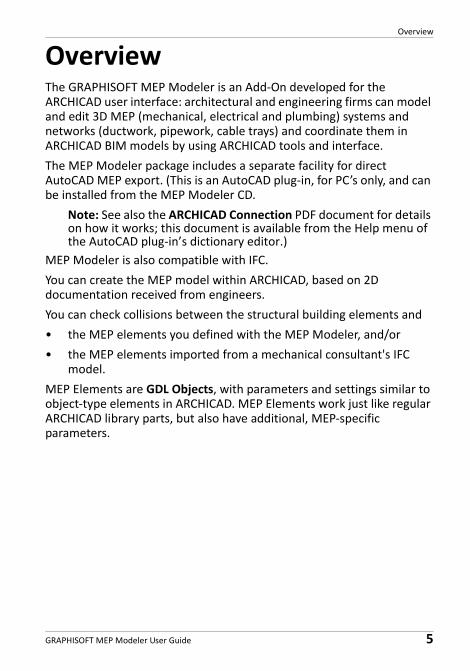
OverviewThe GRAPHISOFT MEP Modeler is an Add‐On developed for the ARCHICAD user interface: architectural and engineering firms can model and edit 3D MEP (mechanical, electrical and plumbing) systems and networks (ductwork, pipework, cable trays) and coordinate them in ARCHICAD BIM models by using ARCHICAD tools and interface.
The MEP Modeler package includes a separate facility for direct AutoCAD MEP export. (This is an AutoCAD plug‐in, for PC’s only, and can be installed from the MEP Modeler CD.
Note: See also the ARCHICAD Connection PDF document for details on how it works; this document is available from the Help menu of the AutoCAD plug‐in’s dictionary editor.)
MEP Modeler is also compatible with IFC.
You can create the MEP model within ARCHICAD, based on 2D documentation received from engineers.
You can check collisions between the structural building elements and
• the MEP elements you defined with the MEP Modeler, and/or
• the MEP elements imported from a mechanical consultant's IFC model.
MEP Elements are GDL Objects, with parameters and settings similar to object‐type elements in ARCHICAD. MEP Elements work just like regular ARCHICAD library parts, but also have additional, MEP‐specific parameters.
Overview
6 GRAPHISOFT MEP Modeler User Guide
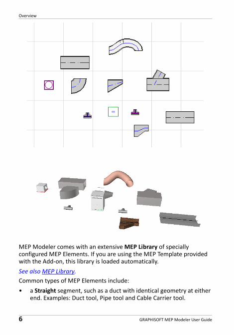
MEP Modeler comes with an extensive MEP Library of specially configured MEP Elements. If you are using the MEP Template provided with the Add‐on, this library is loaded automatically.
See also MEP Library.
Common types of MEP Elements include:
• a Straight segment, such as a duct with identical geometry at either end. Examples: Duct tool, Pipe tool and Cable Carrier tool.
Overview
GRAPHISOFT MEP Modeler User Guide 7
• a Bend. Some Bends are inserted automatically during Routing, or as a result of editing MEP elements, if two otherwise unconnectable elements require that a bend be inserted.
• a Transition. This is a straight segment whose geometries at its two ends are unequal. Transitions are used to connect two MEP elements of different width/height/shape.
• a Junction. These include a Tee junction, a Wye junction, and a Take‐off.
• a Terminal ‐ for example, a ceiling diffuser or a grille or a sprinkler placed at the end of a pipe or duct. A Terminal has only one connection port.
• Inline element, such as a valve or filter, placed inside the route. Inline elements are straight segments open at both ends.
• Equipment ‐ such as a furnace, with one or more connection ports. A single Equipment element generally is generally assigned to multiple MEP Systems (e.g. Heating, Exhaust Air), and are connected to multiple (Pipework, Ductwork) MEP element types.
There are two ways to place MEP Elements:
• Use the MEP Tools to place individual MEP Elements.
• Use the Routing function to place multiple connected MEP Elements with a series of clicks.
Getting Started with MEP Modeler
8 GRAPHISOFT MEP Modeler User Guide
Getting Started with MEP Modeler
Hardware/Software RequirementsThe hardware/software requirements for using MEP Modeler are identical to those of ARCHICAD.
For more details, see “Getting Started with ARCHICAD 20” available from the ARCHICAD Help menu.
LicensesTo run MEP Modeler with your commercially licensed copy of ARCHICAD, you need a separate license for MEP Modeler. (This license can either be located on a hardware protection key, or a network license.)
When applicable, your MEP license will be automatically reserved.
Note: If you don’t want to use a MEP Modeler license every time you start ARCHICAD, uncheck the “Enable MEP Modeling automatically” option in MEP Preferences dialog. In this case, a MEP license is reserved only when you start any of the MEP functions.
If you do not have a license for MEP Modeler, do one of the following:
• Consult your ARCHICAD distributor to obtain one, or
• Use ARCHICAD in demo mode together with MEP Modeler. To do this, switch ARCHICAD to demo mode by removing the ARCHICAD protection key. MEP Modeler’s full functionality is available.
If you have successfully installed MEP Modeler and begun work, but your MEP license is later missing for any reason while you are working with MEP Modeler, a Warning informs you that you have two choices:
1. Obtain the missing license, then continue working; or
2. Continue working in ARCHICAD, without MEP functionality. (The MEP Library remains available, but MEP functions such as Routing are grayed.)
Getting Started with MEP Modeler
GRAPHISOFT MEP Modeler User Guide 9
InstallationTo use the MEP Modeler Add‐On in ARCHICAD, you must install the program.
Download the MEP installer from http://www.graphisoft.com/downloads/MEP/.
When installing MEP Modeler, you must be logged on as a member of the Administrator Group.
Start the installer. The installer wizard will guide you through the installation process.
UninstallTo uninstall MEP Modeler from a PC, it is best to use the “Programs and Features” item from the Control Panel. Alternatively, navigate to the “Uninstall.MEP” folder in your ARCHICAD folder, and select the “Uninstaller” application.
On a Mac, navigate to the “Uninstall.MEP” folder in your ARCHICAD folder, and select the “Uninstaller” application.
MEP Work Environment
10 GRAPHISOFT MEP Modeler User Guide
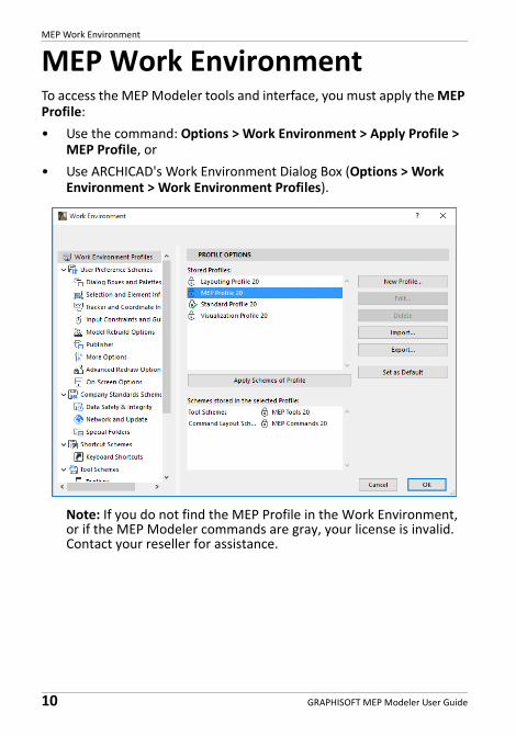
MEP Work EnvironmentTo access the MEP Modeler tools and interface, you must apply the MEP Profile:
• Use the command: Options > Work Environment > Apply Profile > MEP Profile, or
• Use ARCHICAD's Work Environment Dialog Box (Options > Work Environment > Work Environment Profiles).
Note: If you do not find the MEP Profile in the Work Environment, or if the MEP Modeler commands are gray, your license is invalid. Contact your reseller for assistance.
MEP Work Environment
GRAPHISOFT MEP Modeler User Guide 11
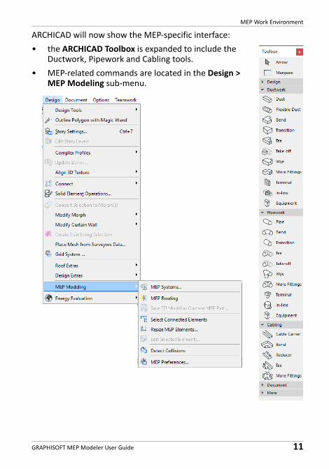
ARCHICAD will now show the MEP‐specific interface:
• the ARCHICAD Toolbox is expanded to include the Ductwork, Pipework and Cabling tools.
• MEP‐related commands are located in the Design > MEP Modeling sub‐menu.
MEP Work Environment
12 GRAPHISOFT MEP Modeler User Guide
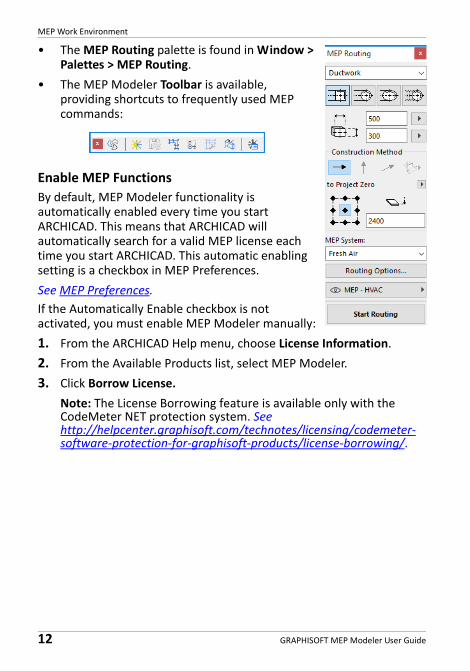
• The MEP Routing palette is found in Window > Palettes > MEP Routing.
• The MEP Modeler Toolbar is available, providing shortcuts to frequently used MEP commands:
Enable MEP Functions
By default, MEP Modeler functionality is automatically enabled every time you start ARCHICAD. This means that ARCHICAD will automatically search for a valid MEP license each time you start ARCHICAD. This automatic enabling setting is a checkbox in MEP Preferences.
See MEP Preferences.
If the Automatically Enable checkbox is not activated, you must enable MEP Modeler manually:
1. From the ARCHICAD Help menu, choose License Information.
2. From the Available Products list, select MEP Modeler.
3. Click Borrow License.
Note: The License Borrowing feature is available only with the CodeMeter NET protection system. See http://helpcenter.graphisoft.com/technotes/licensing/codemeter‐software‐protection‐for‐graphisoft‐products/license‐borrowing/.
MEP Library
GRAPHISOFT MEP Modeler User Guide 13
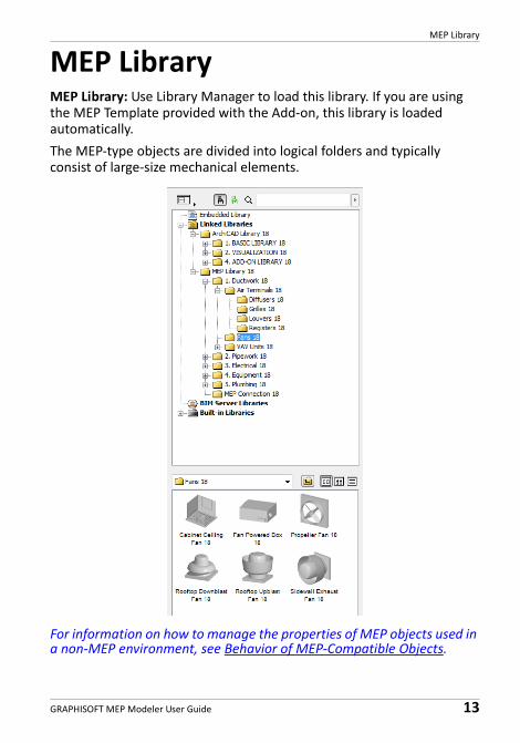
MEP LibraryMEP Library: Use Library Manager to load this library. If you are using the MEP Template provided with the Add‐on, this library is loaded automatically.
The MEP‐type objects are divided into logical folders and typically consist of large‐size mechanical elements.
For information on how to manage the properties of MEP objects used in a non‐MEP environment, see Behavior of MEP‐Compatible Objects.
MEP Connection Ports
14 GRAPHISOFT MEP Modeler User Guide
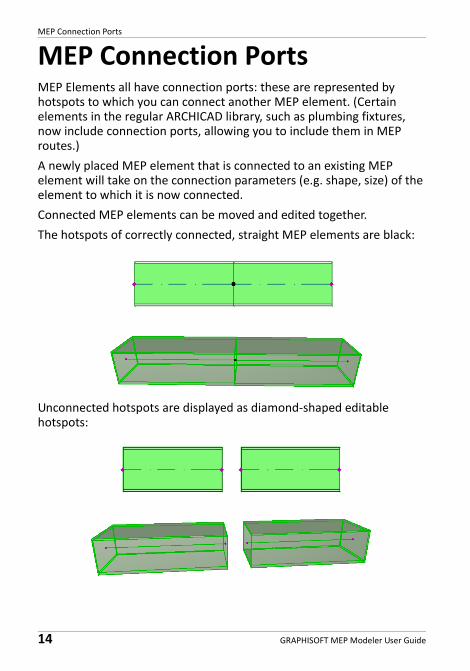
MEP Connection PortsMEP Elements all have connection ports: these are represented by hotspots to which you can connect another MEP element. (Certain elements in the regular ARCHICAD library, such as plumbing fixtures, now include connection ports, allowing you to include them in MEP routes.)
A newly placed MEP element that is connected to an existing MEP element will take on the connection parameters (e.g. shape, size) of the element to which it is now connected.
Connected MEP elements can be moved and edited together.
The hotspots of correctly connected, straight MEP elements are black:
Unconnected hotspots are displayed as diamond‐shaped editable hotspots:
MEP Element Display on Stories
GRAPHISOFT MEP Modeler User Guide 15
MEP Element Display on StoriesThe display of MEP elements on stories depends upon its “Show on Story” setting (Floor Plan and Section panel). The “Show on Story” option of “All Relevant Stories” is used for all MEP elements by default.
With this option, straight segments that intersect stories are displayed as cut on the relevant stories, and the 2D representation (“Projected” or “Symbolic View”) can be set with the “Floor Plan Display” GDL parameter in the 2D Representation group, in the MEP Custom Settings Panel.
Other MEP elements that intersect stories, however, do not have cut displays ‐ they are shown either on one story or the other.
MEP Systems
16 GRAPHISOFT MEP Modeler User Guide
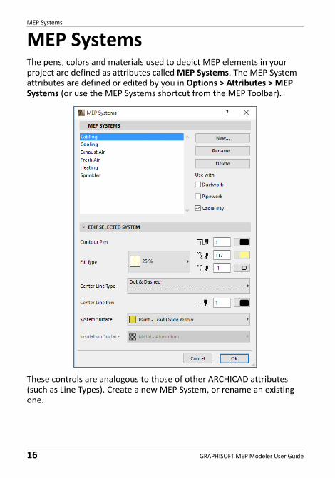
MEP SystemsThe pens, colors and materials used to depict MEP elements in your project are defined as attributes called MEP Systems. The MEP System attributes are defined or edited by you in Options > Attributes > MEP Systems (or use the MEP Systems shortcut from the MEP Toolbar).
These controls are analogous to those of other ARCHICAD attributes (such as Line Types). Create a new MEP System, or rename an existing one.
MEP Systems
GRAPHISOFT MEP Modeler User Guide 17
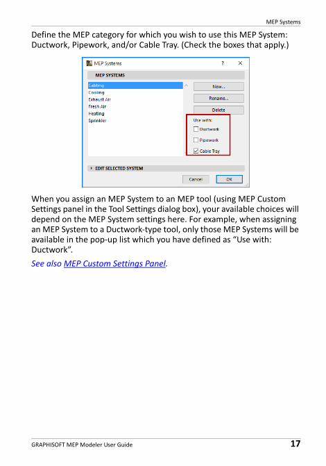
Define the MEP category for which you wish to use this MEP System: Ductwork, Pipework, and/or Cable Tray. (Check the boxes that apply.)
When you assign an MEP System to an MEP tool (using MEP Custom Settings panel in the Tool Settings dialog box), your available choices will depend on the MEP System settings here. For example, when assigning an MEP System to a Ductwork‐type tool, only those MEP Systems will be available in the pop‐up list which you have defined as “Use with: Ductwork”.
See also MEP Custom Settings Panel.
MEP Preferences
18 GRAPHISOFT MEP Modeler User Guide
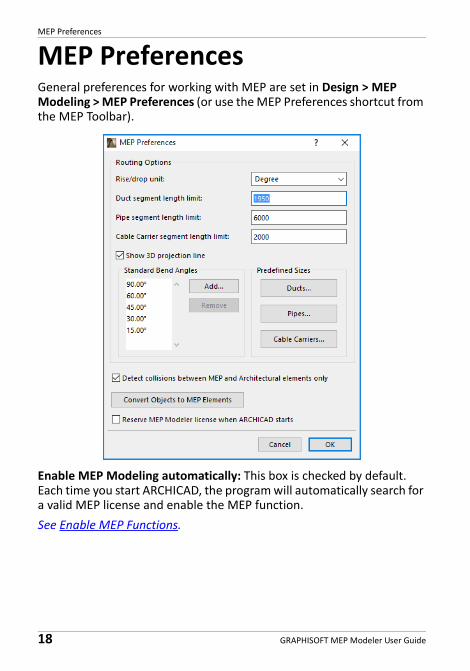
MEP PreferencesGeneral preferences for working with MEP are set in Design > MEP Modeling > MEP Preferences (or use the MEP Preferences shortcut from the MEP Toolbar).
Enable MEP Modeling automatically: This box is checked by default. Each time you start ARCHICAD, the program will automatically search for a valid MEP license and enable the MEP function.
See Enable MEP Functions.
Setting and Editing Element Defaults
GRAPHISOFT MEP Modeler User Guide 19
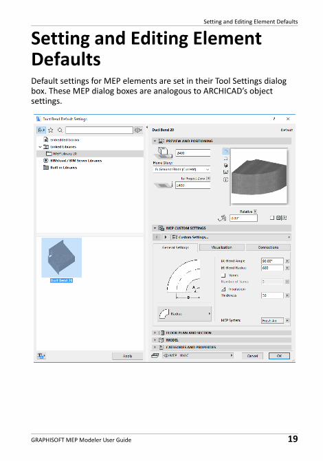
Setting and Editing Element DefaultsDefault settings for MEP elements are set in their Tool Settings dialog box. These MEP dialog boxes are analogous to ARCHICAD’s object settings.
Setting and Editing Element Defaults
20 GRAPHISOFT MEP Modeler User Guide
Preview and Positioning Panel
Set values for the element's position in the model:
• its relative height (measured from the current or home story) • absolute height (from Project Zero or other defined reference level)• rotation angle• mirrored placement of element• Home Story
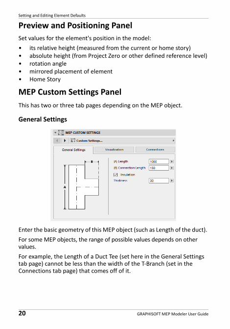
MEP Custom Settings Panel
This has two or three tab pages depending on the MEP object.
General Settings
Enter the basic geometry of this MEP object (such as Length of the duct).
For some MEP objects, the range of possible values depends on other values.
For example, the Length of a Duct Tee (set here in the General Settings tab page) cannot be less than the width of the T‐Branch (set in the Connections tab page) that comes off of it.
Setting and Editing Element Defaults
GRAPHISOFT MEP Modeler User Guide 21
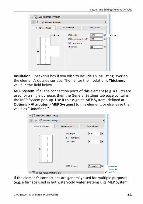
Insulation: Check this box if you wish to include an insulating layer on the element’s outside surface. Then enter the insulation’s Thickness value in the field below.
MEP System: If all the connection ports of this element (e.g. a Duct) are used for a single purpose, then the General Settings tab page contains the MEP System pop‐up. Use it to assign an MEP System (defined at Options > Attributes > MEP Systems) to this element, or else leave the value as “Undefined.”
If the element’s connections are generally used for multiple purposes (e.g. a furnace used in hot water/cold water systems), its MEP System
Setting and Editing Element Defaults
22 GRAPHISOFT MEP Modeler User Guide
attributes are assigned individually to each connection, in the Connections tab page.
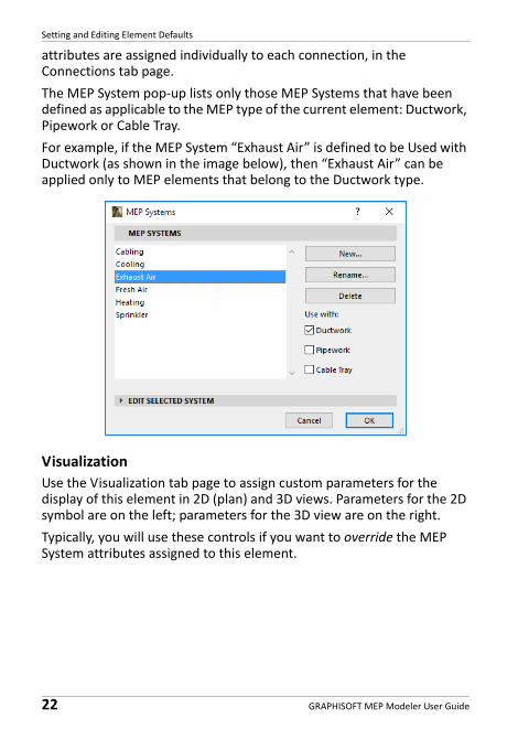
The MEP System pop‐up lists only those MEP Systems that have been defined as applicable to the MEP type of the current element: Ductwork, Pipework or Cable Tray.
For example, if the MEP System “Exhaust Air” is defined to be Used with Ductwork (as shown in the image below), then “Exhaust Air” can be applied only to MEP elements that belong to the Ductwork type.
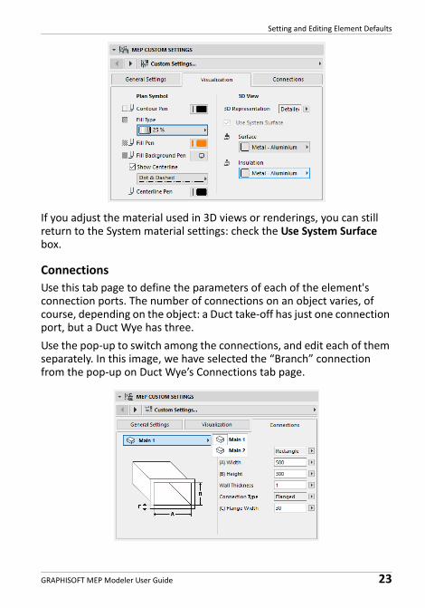
Visualization
Use the Visualization tab page to assign custom parameters for the display of this element in 2D (plan) and 3D views. Parameters for the 2D symbol are on the left; parameters for the 3D view are on the right.
Typically, you will use these controls if you want to override the MEP System attributes assigned to this element.
Setting and Editing Element Defaults
GRAPHISOFT MEP Modeler User Guide 23
If you adjust the material used in 3D views or renderings, you can still return to the System material settings: check the Use System Surface box.
Connections
Use this tab page to define the parameters of each of the element's connection ports. The number of connections on an object varies, of course, depending on the object: a Duct take‐off has just one connection port, but a Duct Wye has three.
Use the pop‐up to switch among the connections, and edit each of them separately. In this image, we have selected the “Branch” connection from the pop‐up on Duct Wye’s Connections tab page.
Setting and Editing Element Defaults
24 GRAPHISOFT MEP Modeler User Guide
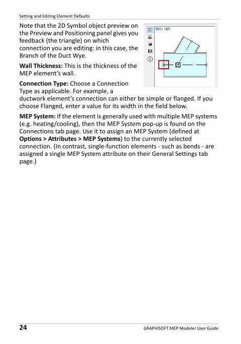
Note that the 2D Symbol object preview on the Preview and Positioning panel gives you feedback (the triangle) on which connection you are editing: in this case, the Branch of the Duct Wye.
Wall Thickness: This is the thickness of the MEP element’s wall.
Connection Type: Choose a Connection Type as applicable. For example, a ductwork element’s connection can either be simple or flanged. If you choose Flanged, enter a value for its width in the field below.
MEP System: If the element is generally used with multiple MEP systems (e.g. heating/cooling), then the MEP System pop‐up is found on the Connections tab page. Use it to assign an MEP System (defined at Options > Attributes > MEP Systems) to the currently selected connection. (In contrast, single‐function elements ‐ such as bends ‐ are assigned a single MEP System attribute on their General Settings tab page.)
Place Individual MEP Elements
GRAPHISOFT MEP Modeler User Guide 25
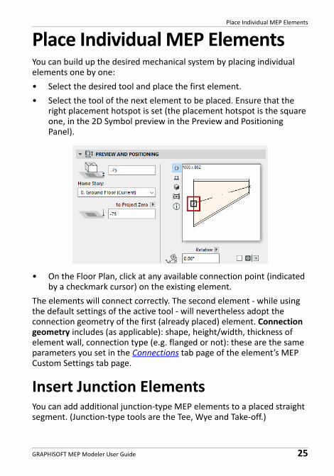
Place Individual MEP ElementsYou can build up the desired mechanical system by placing individual elements one by one:
• Select the desired tool and place the first element.
• Select the tool of the next element to be placed. Ensure that the right placement hotspot is set (the placement hotspot is the square one, in the 2D Symbol preview in the Preview and Positioning Panel).
• On the Floor Plan, click at any available connection point (indicated by a checkmark cursor) on the existing element.
The elements will connect correctly. The second element ‐ while using the default settings of the active tool ‐ will nevertheless adopt the connection geometry of the first (already placed) element. Connection geometry includes (as applicable): shape, height/width, thickness of element wall, connection type (e.g. flanged or not): these are the same parameters you set in the Connections tab page of the element’s MEP Custom Settings tab page.
Insert Junction ElementsYou can add additional junction‐type MEP elements to a placed straight segment. (Junction‐type tools are the Tee, Wye and Take‐off.)
Place Individual MEP Elements
26 GRAPHISOFT MEP Modeler User Guide
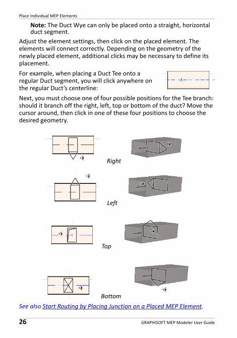
Note: The Duct Wye can only be placed onto a straight, horizontal duct segment.
Adjust the element settings, then click on the placed element. The elements will connect correctly. Depending on the geometry of the newly placed element, additional clicks may be necessary to define its placement.
For example, when placing a Duct Tee onto a regular Duct segment, you will click anywhere on the regular Duct’s centerline:
Next, you must choose one of four possible positions for the Tee branch: should it branch off the right, left, top or bottom of the duct? Move the cursor around, then click in one of these four positions to choose the desired geometry.
Right
Left
Top
Bottom
See also Start Routing by Placing Junction on a Placed MEP Element.
MEP Routing Function
GRAPHISOFT MEP Modeler User Guide 27
MEP Routing FunctionUse the Routing function to place multiple connected MEP Elements with a series of clicks.
Routing is available in the Floor Plan and in the 3D window.
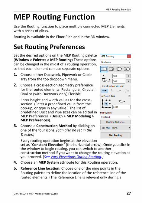
Set Routing PreferencesSet the desired options on the MEP Routing palette (Window > Palettes > MEP Routing) These options can be changed in the midst of a routing operation, so that each element can use separate options.
1. Choose either Ductwork, Pipework or Cable Tray from the top dropdown menu.
2. Choose a cross‐section geometry preference for the routed elements: Rectangular, Circular, Oval or (with Ductwork only) Flexible.
Enter height and width values for the cross‐section. (Enter a predefined value from the pop‐up, or type in any value.) The list of predefined Duct and Pipe sizes can be edited in MEP Preferences. (Design > MEP Modeling > MEP Preferences).
3. Choose a Construction Method by clicking on one of the four icons. (Can also be set in the Tracker.)
Every routing operation begins at the elevation set as “Constant Elevation” (the horizontal arrow). Once you click in the window to begin routing, you can switch to another construction method if you want to change the routing elevation as you proceed. (See Vary Elevations During Routing.)
4. Choose an MEP System attribute for this Routing operation.
5. Reference Line location: Choose one of the nine points in the Routing palette to define the location of the reference line of the routed elements. (The Reference Line is relevant only during a
MEP Routing Function
28 GRAPHISOFT MEP Modeler User Guide
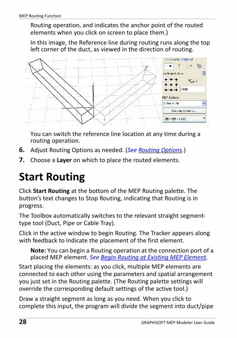
Routing operation, and indicates the anchor point of the routed elements when you click on screen to place them.)
In this image, the Reference line during routing runs along the top left corner of the duct, as viewed in the direction of routing.
You can switch the reference line location at any time during a routing operation.
6. Adjust Routing Options as needed. (See Routing Options.)
7. Choose a Layer on which to place the routed elements.
Start RoutingClick Start Routing at the bottom of the MEP Routing palette. The button’s text changes to Stop Routing, indicating that Routing is in progress.
The Toolbox automatically switches to the relevant straight segment‐type tool (Duct, Pipe or Cable Tray).
Click in the active window to begin Routing. The Tracker appears along with feedback to indicate the placement of the first element.
Note: You can begin a Routing operation at the connection port of a placed MEP element. See Begin Routing at Existing MEP Element.
Start placing the elements: as you click, multiple MEP elements are connected to each other using the parameters and spatial arrangement you just set in the Routing palette. (The Routing palette settings will override the corresponding default settings of the active tool.)
Draw a straight segment as long as you need. When you click to complete this input, the program will divide the segment into duct/pipe
MEP Routing Function
GRAPHISOFT MEP Modeler User Guide 29
segments whose length is defined in Design > MEP Modeling > MEP Preferences: Duct or Pipe Segment Length Limit.
Note: In the Floor Plan window, ARCHICAD's Guide Lines appear during Routing to assist you (provided that Guide Line display is turned on). The Guide Lines during an MEP operation automatically reflect the Standard Bend Angles defined in Design > MEP Modeling > MEP Preferences.
In the 3D window, temporary grids indicate the input plane.
The next click completes the element, but the operation continues: keep clicking to place additional elements on the route.
Press Backspace to delete the most recently placed route element.
Press ESC to cancel a Routing operation.
Finish RoutingClick the Finish Routing button at the bottom of the Routing palette, or Double‐click to complete a Routing operation.
You can also finish Routing by connecting to an already placed MEP element: click on the connection port of the placed element.
If the connection geometries of the connected elements do not match, a Transition element is automatically inserted to ensure a proper connection.
Vary Elevations During RoutingWhen starting any Routing operation, you will click in the window at the elevation value shown as Constant Elevation in the Routing palette (the Construction Method represented by the horizontal arrow). Once you have clicked at that elevation, however, you can choose among alternative methods:
• Vertical Rise: Switch the construction method to “Vertical Rise”. In the Floor Plan, a dialog box appears: enter the elevation at which the next element should end. Click OK to close the dialog box and place the vertical segment, and continue routing. In the 3D window, just draw the segment along the vertical editing plane.
MEP Routing Function
30 GRAPHISOFT MEP Modeler User Guide
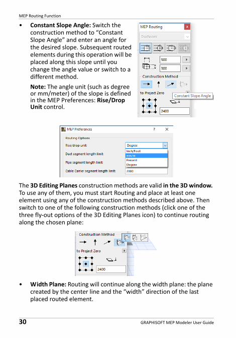
• Constant Slope Angle: Switch the construction method to “Constant Slope Angle” and enter an angle for the desired slope. Subsequent routed elements during this operation will be placed along this slope until you change the angle value or switch to a different method.
Note: The angle unit (such as degree or mm/meter) of the slope is defined in the MEP Preferences: Rise/Drop Unit control.
The 3D Editing Planes construction methods are valid in the 3D window. To use any of them, you must start Routing and place at least one element using any of the construction methods described above. Then switch to one of the following construction methods (click one of the three fly‐out options of the 3D Editing Planes icon) to continue routing along the chosen plane:
• Width Plane: Routing will continue along the width plane: the plane created by the center line and the “width” direction of the last placed routed element.
MEP Routing Function
GRAPHISOFT MEP Modeler User Guide 31
• Height Plane: Routing will continue along the height plane: the plane created by the center line and the “height” direction of the last placed routed element.
• Perpendicular Plane: Routing will continue along the plane perpendicular to that of the last placed element of the Routing operation.
3D input planes are shown as feedback during routing, so it is easy to visualize the result of your chosen input plane.
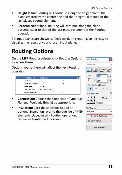
Routing OptionsOn the MEP Routing palette, click Routing Options to access these.
Options you set here will affect the next Routing operation:
• Connection: Choose the Connection Type (e.g. Flanged, Welded, Simple) as appropriate.
• Insulation: Click the checkbox to add an optional Insulation layer to the outside of MEP elements placed in this Routing operation. Define an Insulation Thickness.
MEP Routing Function
32 GRAPHISOFT MEP Modeler User Guide
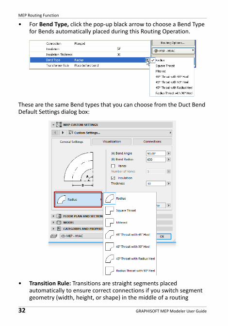
• For Bend Type, click the pop‐up black arrow to choose a Bend Type for Bends automatically placed during this Routing Operation.
These are the same Bend types that you can choose from the Duct Bend Default Settings dialog box:
• Transition Rule: Transitions are straight segments placed automatically to ensure correct connections if you switch segment geometry (width, height, or shape) in the middle of a routing
MEP Routing Function
GRAPHISOFT MEP Modeler User Guide 33
operation. If the switch occurs at a bend in the route, the transition element can be placed either before or after the bend. Choose your preference (“Place before bend”/“Place after bend”) here.
Begin Routing at Existing MEP ElementIf MEP elements have already been placed, you can begin a new routing operation from any of these elements in three different ways:
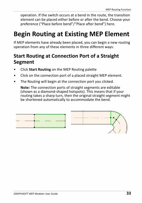
Start Routing at Connection Port of a Straight Segment• Click Start Routing on the MEP Routing palette
• Click on the connection port of a placed straight MEP element.
• The Routing will begin at the connection port you clicked.
Note: The connection ports of straight segments are editable (shown as a diamond‐shaped hotspots). This means that if your routing takes a sharp turn, then the original straight segment might be shortened automatically to accommodate the bend.
MEP Routing Function
34 GRAPHISOFT MEP Modeler User Guide
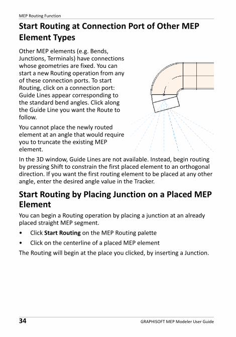
Start Routing at Connection Port of Other MEP Element Types
Other MEP elements (e.g. Bends, Junctions, Terminals) have connections whose geometries are fixed. You can start a new Routing operation from any of these connection ports. To start Routing, click on a connection port: Guide Lines appear corresponding to the standard bend angles. Click along the Guide Line you want the Route to follow.
You cannot place the newly routed element at an angle that would require you to truncate the existing MEP element.
In the 3D window, Guide Lines are not available. Instead, begin routing by pressing Shift to constrain the first placed element to an orthogonal direction. If you want the first routing element to be placed at any other angle, enter the desired angle value in the Tracker.
Start Routing by Placing Junction on a Placed MEP ElementYou can begin a Routing operation by placing a junction at an already placed straight MEP segment.
• Click Start Routing on the MEP Routing palette
• Click on the centerline of a placed MEP element
The Routing will begin at the place you clicked, by inserting a Junction.
MEP Routing Function
GRAPHISOFT MEP Modeler User Guide 35
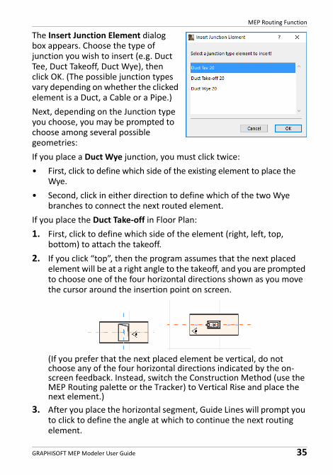
The Insert Junction Element dialog box appears. Choose the type of junction you wish to insert (e.g. Duct Tee, Duct Takeoff, Duct Wye), then click OK. (The possible junction types vary depending on whether the clicked element is a Duct, a Cable or a Pipe.)
Next, depending on the Junction type you choose, you may be prompted to choose among several possible geometries:
If you place a Duct Wye junction, you must click twice:
• First, click to define which side of the existing element to place the Wye.
• Second, click in either direction to define which of the two Wye branches to connect the next routed element.
If you place the Duct Take‐off in Floor Plan:
1. First, click to define which side of the element (right, left, top, bottom) to attach the takeoff.
2. If you click “top”, then the program assumes that the next placed element will be at a right angle to the takeoff, and you are prompted to choose one of the four horizontal directions shown as you move the cursor around the insertion point on screen.
(If you prefer that the next placed element be vertical, do not choose any of the four horizontal directions indicated by the on‐screen feedback. Instead, switch the Construction Method (use the MEP Routing palette or the Tracker) to Vertical Rise and place the next element.)
3. After you place the horizontal segment, Guide Lines will prompt you to click to define the angle at which to continue the next routing element.
MEP Routing Function
36 GRAPHISOFT MEP Modeler User Guide
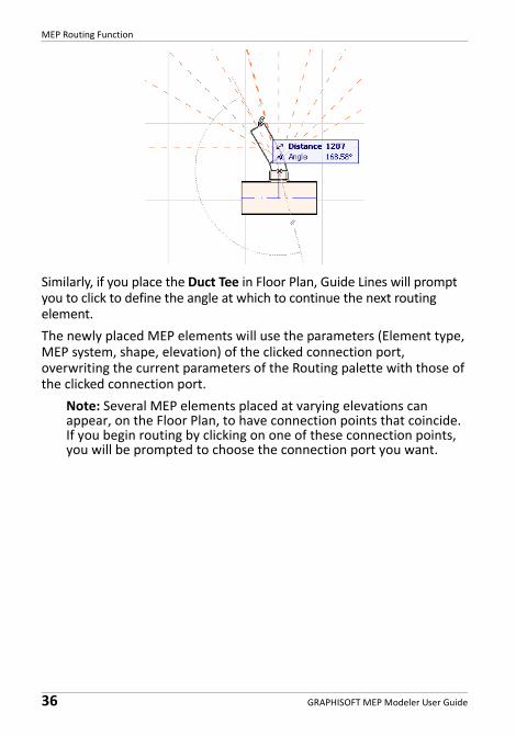
Similarly, if you place the Duct Tee in Floor Plan, Guide Lines will prompt you to click to define the angle at which to continue the next routing element.
The newly placed MEP elements will use the parameters (Element type, MEP system, shape, elevation) of the clicked connection port, overwriting the current parameters of the Routing palette with those of the clicked connection port.
Note: Several MEP elements placed at varying elevations can appear, on the Floor Plan, to have connection points that coincide. If you begin routing by clicking on one of these connection points, you will be prompted to choose the connection port you want.
MEP Routing Function
GRAPHISOFT MEP Modeler User Guide 37
Routing With the Magic WandUse ARCHICAD's Magic Wand function to place a series of connected MEP elements with a single click:
Set preferences on the MEP Routing palette and click Start Routing.
Press the Spacebar to activate the Magic Wand, then click on an existing polyline or polygon.
The MEP route is placed.
In contrast to the Magic Wand operation with regular ARCHICAD tools, the Magic Wand used during MEP Routing will not reproduce curved elements; a straight segment will connect the two endpoints of the curved element. Thus, all MEP routed elements placed using the Magic Wand method will be straight segments (connected by bends as needed).
Note: The Magic Wand method for placing routed elements works only as the initial step in an MEP Routing operation.
Editing MEP Elements
38 GRAPHISOFT MEP Modeler User Guide
Editing MEP Elements• MEP‐specific editing operations are available in the Floor Plan and
3D window. (In the Section/Elevation/IE windows, only the basic ‐ Move, Stretch ‐ editing commands are available.)
• For any selected MEP element, use its Settings dialog to edit its parameters. Use the Pet Palette commands to edit the MEP element graphically.
• When you edit a selected MEP element, certain parameters of connected (though unselected) MEP elements may also change as a result.
• Following the edit, every modified element becomes selected.For example, if you change the cross‐section of one selected element, the connected elements will become disconnected as a result, and they will all be shown as selected following the edit.
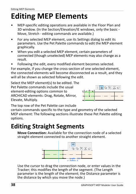
Select the MEP element(s) to be edited. The Pet Palette commands include the usual element‐editing options common to ARCHICAD elements: Drag, Rotate, Mirror, Elevate, Multiply.
The top row of the Pet Palette can include certain commands specific to the type and geometry of the selected MEP element: The following sections illustrate these Pet Palette editing options.
Editing Straight SegmentsMove Connection: Available for the connection node of a selected straight element connected to another straight element.
Use the cursor to drag the connection node, or enter values in the Tracker; this modifies the length of the segment. (The Length parameter is the length of the element; the Distance parameter is the distance by which you move the node.)
Editing MEP Elements
GRAPHISOFT MEP Modeler User Guide 39
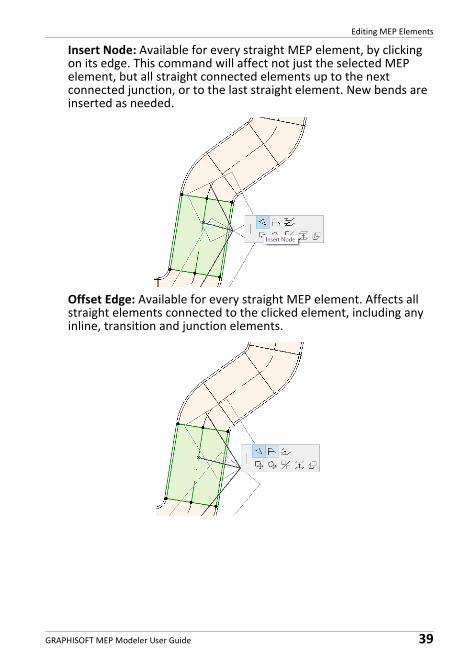
Insert Node: Available for every straight MEP element, by clicking on its edge. This command will affect not just the selected MEP element, but all straight connected elements up to the next connected junction, or to the last straight element. New bends are inserted as needed.
Offset Edge: Available for every straight MEP element. Affects all straight elements connected to the clicked element, including any inline, transition and junction elements.
Editing MEP Elements
40 GRAPHISOFT MEP Modeler User Guide
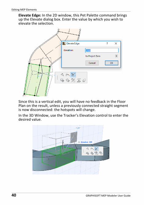
Elevate Edge: In the 2D window, this Pet Palette command brings up the Elevate dialog box. Enter the value by which you wish to elevate the selection.
Since this is a vertical edit, you will have no feedback in the Floor Plan on the result, unless a previously connected straight segment is now disconnected: the hotspots will change.
In the 3D Window, use the Tracker’s Elevation control to enter the desired value.
Editing MEP Elements
GRAPHISOFT MEP Modeler User Guide 41
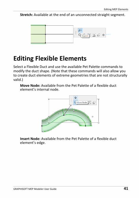
Stretch: Available at the end of an unconnected straight segment.
Editing Flexible ElementsSelect a Flexible Duct and use the available Pet Palette commands to modify the duct shape. (Note that these commands will also allow you to create duct elements of extreme geometries that are not structurally valid.)
Move Node: Available from the Pet Palette of a flexible duct element’s internal node.
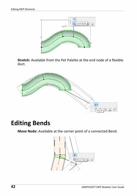
Insert Node: Available from the Pet Palette of a flexible duct element’s edge.
Editing MEP Elements
42 GRAPHISOFT MEP Modeler User Guide
Stretch: Available from the Pet Palette at the end node of a flexible duct.
Editing BendsMove Node: Available at the corner point of a connected Bend.
Editing MEP Elements
GRAPHISOFT MEP Modeler User Guide 43
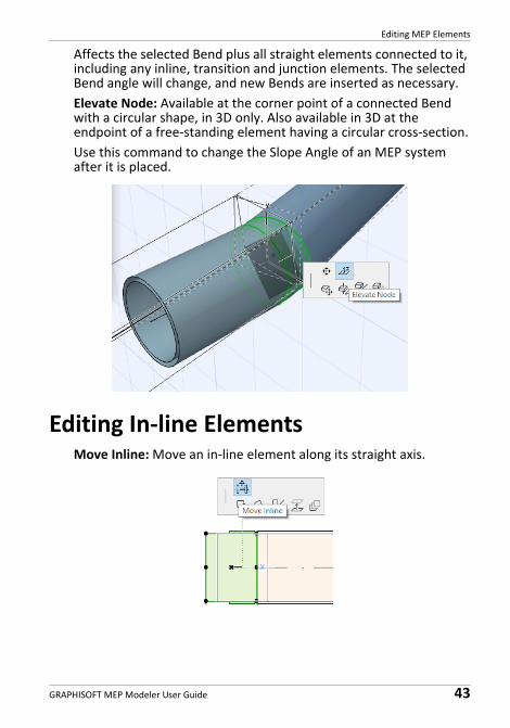
Affects the selected Bend plus all straight elements connected to it, including any inline, transition and junction elements. The selected Bend angle will change, and new Bends are inserted as necessary.
Elevate Node: Available at the corner point of a connected Bend with a circular shape, in 3D only. Also available in 3D at the endpoint of a free‐standing element having a circular cross‐section.
Use this command to change the Slope Angle of an MEP system after it is placed.
Editing In‐line ElementsMove Inline: Move an in‐line element along its straight axis.
Editing MEP Elements
44 GRAPHISOFT MEP Modeler User Guide
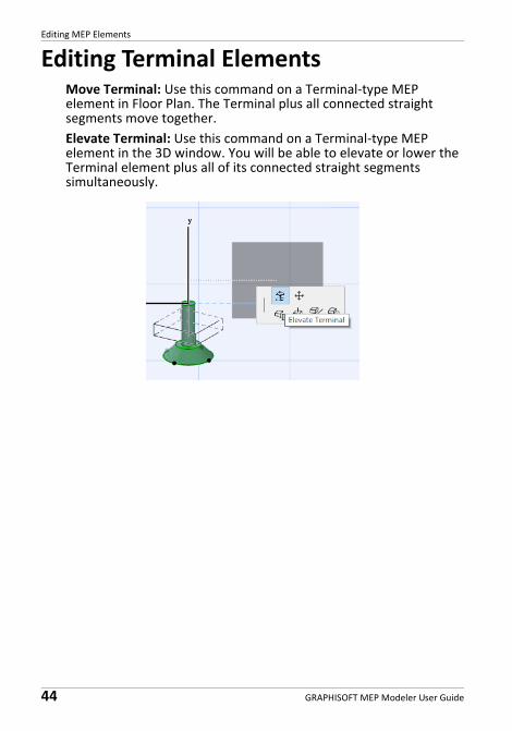
Editing Terminal ElementsMove Terminal: Use this command on a Terminal‐type MEP element in Floor Plan. The Terminal plus all connected straight segments move together.
Elevate Terminal: Use this command on a Terminal‐type MEP element in the 3D window. You will be able to elevate or lower the Terminal element plus all of its connected straight segments simultaneously.
Resize MEP Elements
GRAPHISOFT MEP Modeler User Guide 45
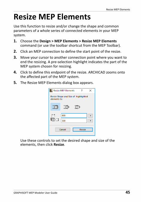
Resize MEP ElementsUse this function to resize and/or change the shape and common parameters of a whole series of connected elements in your MEP system.
1. Choose the Design > MEP Elements > Resize MEP Elements command (or use the toolbar shortcut from the MEP Toolbar).
2. Click an MEP connection to define the start point of the resize.
3. Move your cursor to another connection point where you want to end the resizing. A pre‐selection highlight indicates the part of the MEP system chosen for resizing.
4. Click to define this endpoint of the resize. ARCHICAD zooms onto the affected part of the MEP system.
5. The Resize MEP Elements dialog box appears.
Use these controls to set the desired shape and size of the elements, then click Resize.
Select Connected MEP Elements
46 GRAPHISOFT MEP Modeler User Guide
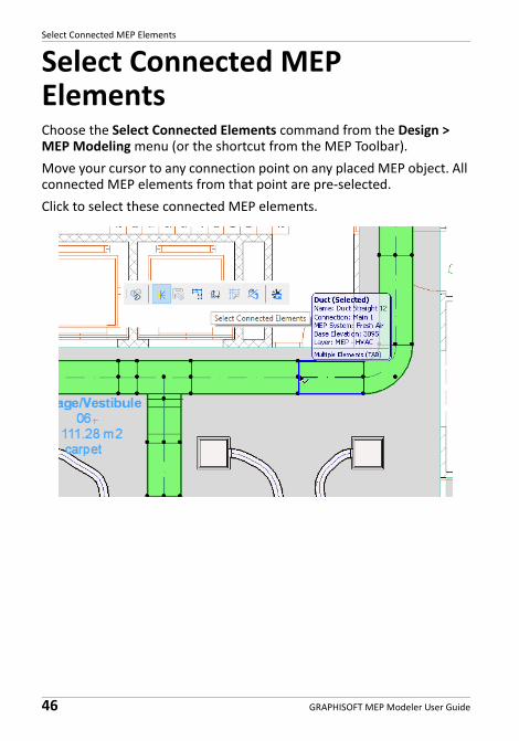
Select Connected MEP ElementsChoose the Select Connected Elements command from the Design > MEP Modeling menu (or the shortcut from the MEP Toolbar).
Move your cursor to any connection point on any placed MEP object. All connected MEP elements from that point are pre‐selected.
Click to select these connected MEP elements.
Edit Selected Elements
GRAPHISOFT MEP Modeler User Guide 47
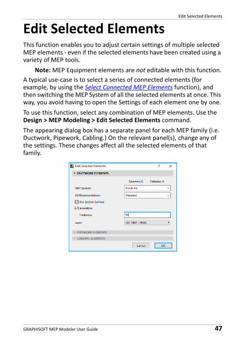
Edit Selected ElementsThis function enables you to adjust certain settings of multiple selected MEP elements ‐ even if the selected elements have been created using a variety of MEP tools.
Note: MEP Equipment elements are not editable with this function.
A typical use‐case is to select a series of connected elements (for example, by using the Select Connected MEP Elements function), and then switching the MEP System of all the selected elements at once. This way, you avoid having to open the Settings of each element one by one.
To use this function, select any combination of MEP elements. Use the Design > MEP Modeling > Edit Selected Elements command.
The appearing dialog box has a separate panel for each MEP family (i.e. Ductwork, Pipework, Cabling.) On the relevant panel(s), change any of the settings. These changes affect all the selected elements of that family.
Collision Detection
48 GRAPHISOFT MEP Modeler User Guide
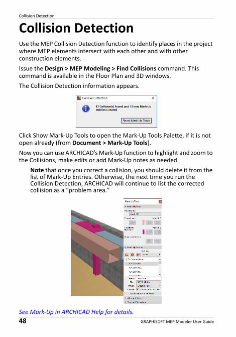
Collision DetectionUse the MEP Collision Detection function to identify places in the project where MEP elements intersect with each other and with other construction elements.
Issue the Design > MEP Modeling > Find Collisions command. This command is available in the Floor Plan and 3D windows.
The Collision Detection information appears.
Click Show Mark‐Up Tools to open the Mark‐Up Tools Palette, if it is not open already (from Document > Mark‐Up Tools).
Now you can use ARCHICAD’s Mark‐Up function to highlight and zoom to the Collisions, make edits or add Mark‐Up notes as needed.
Note that once you correct a collision, you should delete it from the list of Mark‐Up Entries. Otherwise, the next time you run the Collision Detection, ARCHICAD will continue to list the corrected collision as a “problem area.”
See Mark‐Up in ARCHICAD Help for details.
Collision Detection
GRAPHISOFT MEP Modeler User Guide 49
Which Elements Participate in Collision Detection?
Collision detection is based on Element Classification (Categories and Properties), not on ARCHICAD tool type. As a result, collision detection works on:
• all imported IFC MEP elements (regardless of which MEP application exported the IFC model), and
• all ARCHICAD project MEP Objects and MEP‐classified elements (for example pipes defined with Beam tool, but classified as MEP elements).
If any MEP elements are selected, Collision Detection will be restricted to the selected MEP elements.
If nothing is selected, Collision Detection will review all elements classified as MEP‐type in Element Settings (Categories and Properties > Element Classification).
The collision detection function works between solid and solid and between solid and open shell geometries, and includes qualifying elements which are part of Modules or Groups, and which are located on locked layers.
Collision Detection does not include non‐visible elements (those on hidden layers).
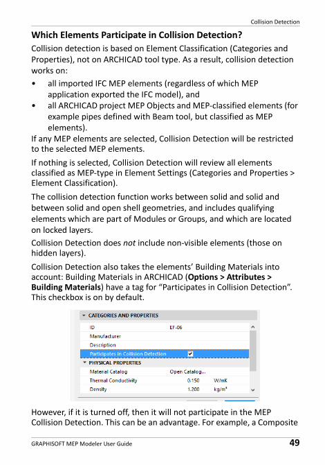
Collision Detection also takes the elements’ Building Materials into account: Building Materials in ARCHICAD (Options > Attributes > Building Materials) have a tag for “Participates in Collision Detection”. This checkbox is on by default.
However, if it is turned off, then it will not participate in the MEP Collision Detection. This can be an advantage. For example, a Composite

Collision Detection
50 GRAPHISOFT MEP Modeler User Guide
Wall can include the Air Space Building Material. The HVAC system can be built in to this skin. If that Air Space Building Material is defined with the Collision Detection checkbox set to “Off”, then no collision occurs.
Create Custom MEP Part
GRAPHISOFT MEP Modeler User Guide 51
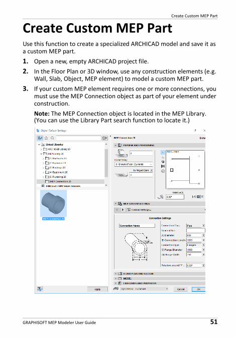
Create Custom MEP PartUse this function to create a specialized ARCHICAD model and save it as a custom MEP part.
1. Open a new, empty ARCHICAD project file.
2. In the Floor Plan or 3D window, use any construction elements (e.g. Wall, Slab, Object, MEP element) to model a custom MEP part.
3. If your custom MEP element requires one or more connections, you must use the MEP Connection object as part of your element under construction.
Note: The MEP Connection object is located in the MEP Library. (You can use the Library Part search function to locate it.)
Create Custom MEP Part
52 GRAPHISOFT MEP Modeler User Guide
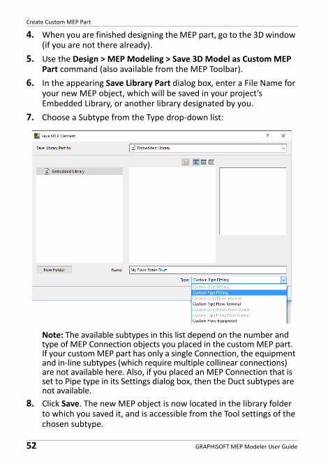
4. When you are finished designing the MEP part, go to the 3D window (if you are not there already).
5. Use the Design > MEP Modeling > Save 3D Model as Custom MEP Part command (also available from the MEP Toolbar).
6. In the appearing Save Library Part dialog box, enter a File Name for your new MEP object, which will be saved in your project’s Embedded Library, or another library designated by you.
7. Choose a Subtype from the Type drop‐down list:
Note: The available subtypes in this list depend on the number and type of MEP Connection objects you placed in the custom MEP part. If your custom MEP part has only a single Connection, the equipment and in‐line subtypes (which require multiple collinear connections) are not available here. Also, if you placed an MEP Connection that is set to Pipe type in its Settings dialog box, then the Duct subtypes are not available.
8. Click Save. The new MEP object is now located in the library folder to which you saved it, and is accessible from the Tool settings of the chosen subtype.
Behavior of MEP‐Compatible Objects
GRAPHISOFT MEP Modeler User Guide 53
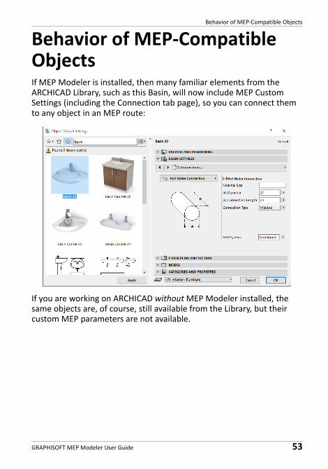
Behavior of MEP‐Compatible ObjectsIf MEP Modeler is installed, then many familiar elements from the ARCHICAD Library, such as this Basin, will now include MEP Custom Settings (including the Connection tab page), so you can connect them to any object in an MEP route:
If you are working on ARCHICAD without MEP Modeler installed, the same objects are, of course, still available from the Library, but their custom MEP parameters are not available.
Behavior of MEP‐Compatible Objects
54 GRAPHISOFT MEP Modeler User Guide
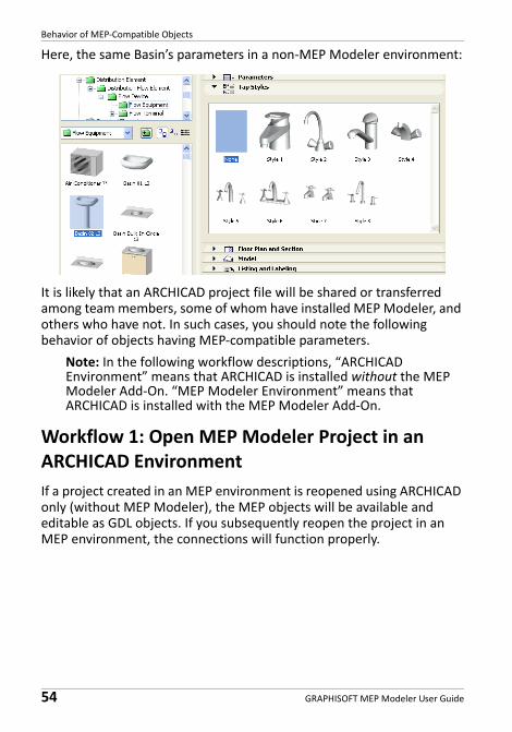
Here, the same Basin’s parameters in a non‐MEP Modeler environment:
It is likely that an ARCHICAD project file will be shared or transferred among team members, some of whom have installed MEP Modeler, and others who have not. In such cases, you should note the following behavior of objects having MEP‐compatible parameters.
Note: In the following workflow descriptions, “ARCHICAD Environment” means that ARCHICAD is installed without the MEP Modeler Add‐On. “MEP Modeler Environment” means that ARCHICAD is installed with the MEP Modeler Add‐On.
Workflow 1: Open MEP Modeler Project in an ARCHICAD Environment
If a project created in an MEP environment is reopened using ARCHICAD only (without MEP Modeler), the MEP objects will be available and editable as GDL objects. If you subsequently reopen the project in an MEP environment, the connections will function properly.
Behavior of MEP‐Compatible Objects
GRAPHISOFT MEP Modeler User Guide 55
Workflow 2: Open ARCHICAD Project in an MEP Modeler Environment
If an ARCHICAD project is opened (using File > Open) in an MEP Modeler environment, then the GDL objects that are MEP‐compatible will be automatically “smartened up” to include MEP Custom Settings and connection parameters. Their connection parameters can be used to include these objects as part of an MEP route. Adjacent MEP objects with connected hotspots are automatically connected (provided that the connection geometries are compatible).
Workflow 3: Merge, Copy‐Paste, or Send/Receive ARCHICAD Project in an MEP Modeler Environment
If an ARCHICAD project is accessed in an MEP environment without using File > Open (e.g. merging the file; or copy/pasting MEP objects; or accessing such objects through Teamwork’s Send/Receive or Reserve functions), then the MEP‐compatible GDL objects will not automatically be converted into parametric MEP objects, as they are in Workflow 2.
If you want continue working on this project using MEP Modeler functions, you should achieve this conversion manually: go to MEP Preferences and click the Convert Objects to MEP Elements button.

Behavior of MEP‐Compatible Objects
56 GRAPHISOFT MEP Modeler User Guide