Embed Size (px)
Citation preview
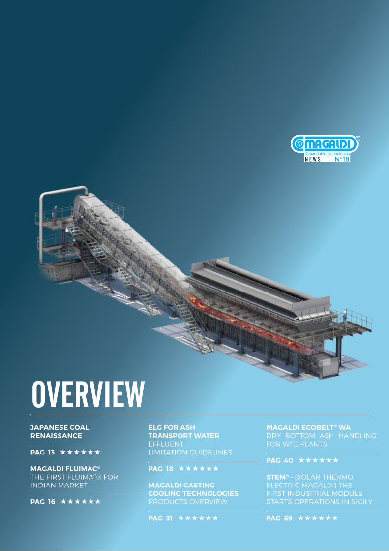
N E W S N°18
ovErviEWJapanese coal renaissance
paG 13 ★★★★★★
MaGaldi FluiMac®
The firsT fluimac® for indian markeT
paG 16 ★★★★★★
elG For ash TransporT WaTereffluenT limiTaTion Guidelines
paG 18 ★★★★★★
MaGaldi casTinG coolinG TechnoloGiesProducTs oVerVieW
paG 31 ★★★★★★
MaGaldi ecoBelT® WadrY BoTTom ash handlinG for WTe PlanTs
paG 40 ★★★★★★
sTeM® - (solar Thermo elecTric maGaldi) The firsT indusTrial module sTarTs oPeraTions in sicilY
paG 59 ★★★★★★

Editorial 5 Mario Magaldi PresideNt & Ceo Magaldi grouP
Magaldi EcobElt® 6Tufanbeyli (Turkey) power sTaTion MiChele Corradosales teaM leader Power [email protected]
thE Eighth Magaldi SyStEM iN chilE 10 red dragon Thermal power planT ivaNo PeNNellaarea [email protected]
alfoNso Pirroarea [email protected]
JapaNESE coal rENaiSSaNcE 13 ivaNo PeNNellaarea MaNager [email protected]
thE cENal 2 x 660 MW proJEct 15The firsT ulTra-supercriTical boilers in Turkey siMoNe savastaNoarea MaNager [email protected]
Magaldi FluiMac® 16The firsT fluimac® for indian markeT debasish Chakraberty Magaldi Power iNdia Pvt. ltd. CouNtry MaNager [email protected]
MiChele Corradosales teaM leader Power [email protected]
loreNzo lePore ProCess [email protected]
Elg For aSh traNSport WatEr 18effluenT limiTaTion guidelines keith holtMagaldi teChNologies llC sales area [email protected]
daNiele CoPPola area [email protected]
SaviNg WatEr iN iNdiaN poWEr plaNtS 20magaldi dry ash handling Technologies debasish ChakrabertyMagaldi Power iNdia Pvt. ltd. CouNtry MaNager [email protected]
sudiPto ChakravortyMagaldi Power iNdia Pvt. ltd. area [email protected]
fulvio bassettiteChNiCal [email protected]
loreNzo lePore ProCess [email protected]
dry bottoM aSh haNdliNg SyStEM 28improving mainTainabiliTy and economic efficiency kawasaki teChNiCal review No.176 february 2016
Magaldi caStiNg cooliNg tEchNologiES 31producTs overview
aNtoNello Marrazzoarea MaNager [email protected]
gaetaNo CoraggioProCess eNgiNeer [email protected]
Magaldi caStiNg cooliNg tEchNologiES 36case sTudies
aNtoNello Marrazzosales area MaNager [email protected]
gaetaNo CoraggioProCess [email protected]
Magaldi EcobElt® Wa 40 dry boTTom ash handling for wTe planTs aNgelo de geNNaro area MaNager [email protected]
alfoNso Pirroarea [email protected]
daNiele riCCiseNior ProCess [email protected]
Magaldi SupErbElt® coNvEyor iN FouNdry 44 general overview
alberto lalia area MaNager [email protected]
Magaldi EcobElt® bio 48 dry boTTom ash handling for biomass fired boilers
Matteo CarfagNo area MaNager [email protected]
daNiele riCCi seNior ProCess eNgiNeer [email protected]
Magaldi SupErbElt® WEighiNg FEEdEr 52 alberto lalia area [email protected]
Magaldi SupErbElt® hd 53 conTinuous sTeel scrap TransporTaTion
Matteo CarfagNo area [email protected]
Magaldi EcobElt® 55 a dependable choice for The recycling aluminium process
saverio vitale area [email protected]
doMeNiCo Casillo teChNiCal [email protected]
Magaldi tEchNologiES llc 58 The usa subsidiary
Charles strasburger Magaldi teChNologies llC sales area [email protected]
StEM® 59 (solar Thermo elecTric magaldi)The firsT indusTrial module sTarTs operaTions in sicily
letizia Magaldi PubliC relatioNs aNd MeMber of the [email protected]
fulvio bassetti teChNiCal [email protected]
c o n T e n T s
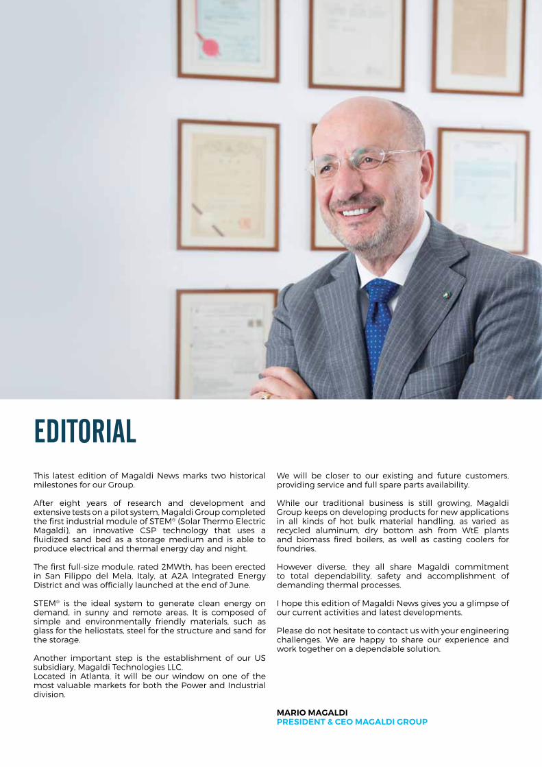
EditorialThis latest edition of magaldi news marks two historical milestones for our Group.
after eight years of research and development and extensive tests on a pilot system, magaldi Group completed the first industrial module of sTem® (solar Thermo electric magaldi), an innovative csP technology that uses a fluidized sand bed as a storage medium and is able to produce electrical and thermal energy day and night.
The first full-size module, rated 2mWth, has been erected in san filippo del mela, italy, at a2a integrated energy district and was officially launched at the end of June.
sTem® is the ideal system to generate clean energy on demand, in sunny and remote areas. it is composed of simple and environmentally friendly materials, such as glass for the heliostats, steel for the structure and sand for the storage.
another important step is the establishment of our us subsidiary, magaldi Technologies llc. located in atlanta, it will be our window on one of the most valuable markets for both the Power and industrial division.
We will be closer to our existing and future customers, providing service and full spare parts availability.
While our traditional business is still growing, magaldi Group keeps on developing products for new applications in all kinds of hot bulk material handling, as varied as recycled aluminum, dry bottom ash from Wte plants and biomass fired boilers, as well as casting coolers for foundries.
however diverse, they all share magaldi commitment to total dependability, safety and accomplishment of demanding thermal processes.
i hope this edition of magaldi news gives you a glimpse of our current activities and latest developments.
Please do not hesitate to contact us with your engineering challenges. We are happy to share our experience and work together on a dependable solution.
Mario MaGaldipresidenT & ceo MaGaldi Group
N E W S N°185
P.s, i am honored to share with you the following recent endorsements:
Editorial
Mario Magaldi PresideNt & Ceo Magaldi grouP
hon Mike rann ac cnZM, preMier oF souTh ausTralia 2002-2011, ForMer MinisTer For susTainaBiliTy and cliMaTe chanGe and econoMic developMenT.
“now that sTem® has moved from prototype to commercial application it is clear that this is a breakthrough, scalable renewable energy technology that deserves the closest examination. for me sTem is a real advance on other forms of csP, particularly in terms of storage. it doesn’t need batteries and can keep generating electricity on an industrial scale at night as well as during the day. as with other technological advances sTem®’s great strength is its simplicity. it produces energy more cleanly, more cheaply, more efficiently and with lower maintenance. i was first attracted to magaldi’s sTem® because of its potential for rural and remote “outback” communities, mines and mining camps around australia that are not connected to the electricity grid and currently rely on expensive and polluting diesel. i am sure sTem®’s application will, of course, be much wider. There is already interest from india and southern europe and its potential for africa and the americas is massive. i am proud to be associated with magaldi’s sTem® and encourage its examination for a range of off-grid applications.”
proFessor TiM Flannery, chieF councillor cliMaTe council, ausTralian oF The year 2007.
“The commissioning of magaldi industry’s first commercial-scale sTem® solar thermoelectric power plant marks a major milestone in the global shift to renewable energy. able to generate electricity even when the sun is down, sTem® represents a fundamental breakthrough. utilising only steel and silica in its construction, it is simple to operate and maintain, and provides industrial scale generation without the use of batteries in scaleable, half-megawatt units, sTem® is perfectly adapted for powering towns and small cities in the developing world. But because it also generates heat, it is ideally suited for use in the fast-growing greenhouse sector, and as an energy provider for many industrial processes. as an australian, i’m tremendously excited at the prospect of an innovation with the potential to generate cheap and abundant energy and fresh water using only sunlight.”
r.k. pachauri, ForMer chairMan, inTerGovernMenTal panel on cliMaTe chanGe (ipcc), and ForMer chairMan, The enerGy and resources insTiTuTe (Teri). noBel priZe For peace 2007
“solar thermal technology has been an area of major research and development with enormous promise. in this regard, the sTem® technology developed by the magaldi Group is a revolutionary development, because not only does it provide an effective means for storage and utilization of energy for long periods, but it is able to do so with the use of silica sand, which is simple, cost effective and eliminates the use of chemicals and toxic materials. i have no hesitation in stating that the sTem® technology provides a unique opportunity to produce energy without emissions of greenhouse gases, and carbon dioxide in particular, but it also opens up opportunities for decentralized and distributed generation in many parts of the world, where energy access is a serious problem. i would expect that sTem® will find widespread application in a number of industrial applications, in rural areas in the developing world and for power supply to the grid across the globe. This technology would be an effective means for mitigation of emissions of greenhouse gases and for providing energy in fulfillment of the 7th among the 17 sustainable development Goals adopted by the un General assembly.”
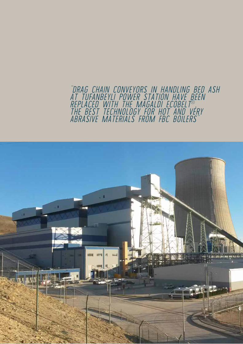
“Drag chain conveyors in hanDling beD ash at tufanbeyli power station have been replaceD with the MagalDi ecobelt®, the best technology for hot anD very abrasive Materials froM fbc boilers”
N E W S N°187
Magaldi EcobElt®Tufanbeyli (Turkey) power sTaTion
M. Corradosales teaM leader Power divisioN
Magaldi EcobElt®Tufanbeyli (Turkey) power sTaTion
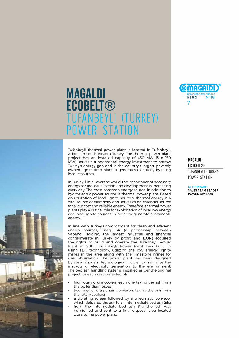
Tufanbeyli thermal power plant is located in Tufanbeyli, adana, in south-eastern Turkey. The thermal power plant project has an installed capacity of 450 mW (3 x 150 mW), serves a fundamental energy investment to narrow Turkey’s energy gap and is the country’s largest privately owned lignite-fired plant. it generates electricity by using local resources.
in Turkey, like all over the world, the importance of necessary energy for industrialization and development is increasing every day. The most common energy source, in addition to hydroelectric power source, is thermal power plant. Based on utilization of local lignite sources, thermal energy is a vital source of electricity and serves as an essential source for a low cost and reliable energy. Therefore, thermal power plants play a critical role for exploitation of local low energy coal and lignite sources in order to generate sustainable energy.
in line with Turkey’s commitment for clean and efficient energy sources, enerji sa (a partnership between sabancı holding, the largest industrial and financial conglomerate in Turkey by profit, and e.on) acquired the rights to build and operate the Tufanbeyli Power Plant in 2006. Tufanbeyli Power Plant was built by using fBc technology, utilizing the low energy lignite mines in the area along with the limestone mines for desulphurization. The power plant has been designed by using modern technologies in order to minimize the impacts of electricity generation to the environment. The bed ash handling systems installed as per the original project for each unit consisted of:
• fourrotarydrumcoolers,eachonetakingtheashfromthe boiler drain pipes;
• two linesofdragchainconveyors taking theash fromthe rotary coolers;
• a vibrating screen followed by a pneumatic conveyorwhich delivered the ash to an intermediate bed ash silo;
• from the intermediate bed ash Silo the ash washumidified and sent to a final disposal area located close to the power plant.
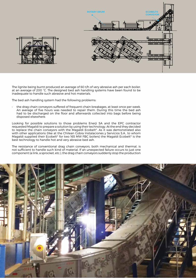
The lignite being burnt produced an average of 60 t/h of very abrasive ash per each boiler, at an average of 200 °c. The designed bed ash handling systems have been found to be inadequate to handle such abrasive and hot materials.
The bed ash handling system had the following problems:
• thedragchainconveyorssufferedoffrequentchainbreakages,atleastonceperweek.an average of five hours was needed to repair them. during this time the bed ash had to be discharged on the floor and afterwards collected into bags before being disposed elsewhere.
looking for possible solutions to those problems enerji sa and the ePc contractor requested magaldi to prepare a solution by using their technology. at the end they decided to replace the chain conveyors with the magaldi ecobelt®. as it was demonstrated also with other applications (like at the chilean cobra instalaciones y servicios s.a., to whom magaldi supplied their ecobelt® for two 165 mW fBc boilers) the magaldi ecobelt® is the best technology to handle hot and very abrasive bed ash.
The resistance of conventional drag chain conveyors, both mechanical and thermal, is not sufficient to handle such kind of material. if an unexpected failure occurs to just one component (a link, a sprocket, etc.), the drag chain conveyors suddenly stop the production
ROTARY DRUM ECOBELT®CONVEYOR
N E W S N°189
line for the whole period necessary to repair the breakage (like it happened at Tufanbeyli power plant). The major causes of a component failure of the chain conveyors are the abrasion, high temperature and corrosion characteristics of handled materials. This high wear is caused by the relative motion between the conveyor parts and the handled abrasive ash. drag chain conveyors are not appropriate for moving larger objects too, since they are very likely to get jammed, leading to increased incidence of maintenance and repair. These conveyors can encounter other problems such as the tendency of the chain to jump the sprocket teeth, due to excessive chain stretch / elongation, or the misalignment of multiple chain strands caused by uneven wear and / or tension.nowadays the above-mentioned losses, associated with unexpected and frequent downtimes of conveyors, are not acceptable.
The magaldi ecobelt®, as it will be the case for Tufanbeyli project, overcomes the limitations of conventional handling systems such as drag chain conveyors. The magaldi ecobelt® is the ideal solution to withstand high temperatures, abrasiveness, sharp edges and heavy weights of different bulk materials.
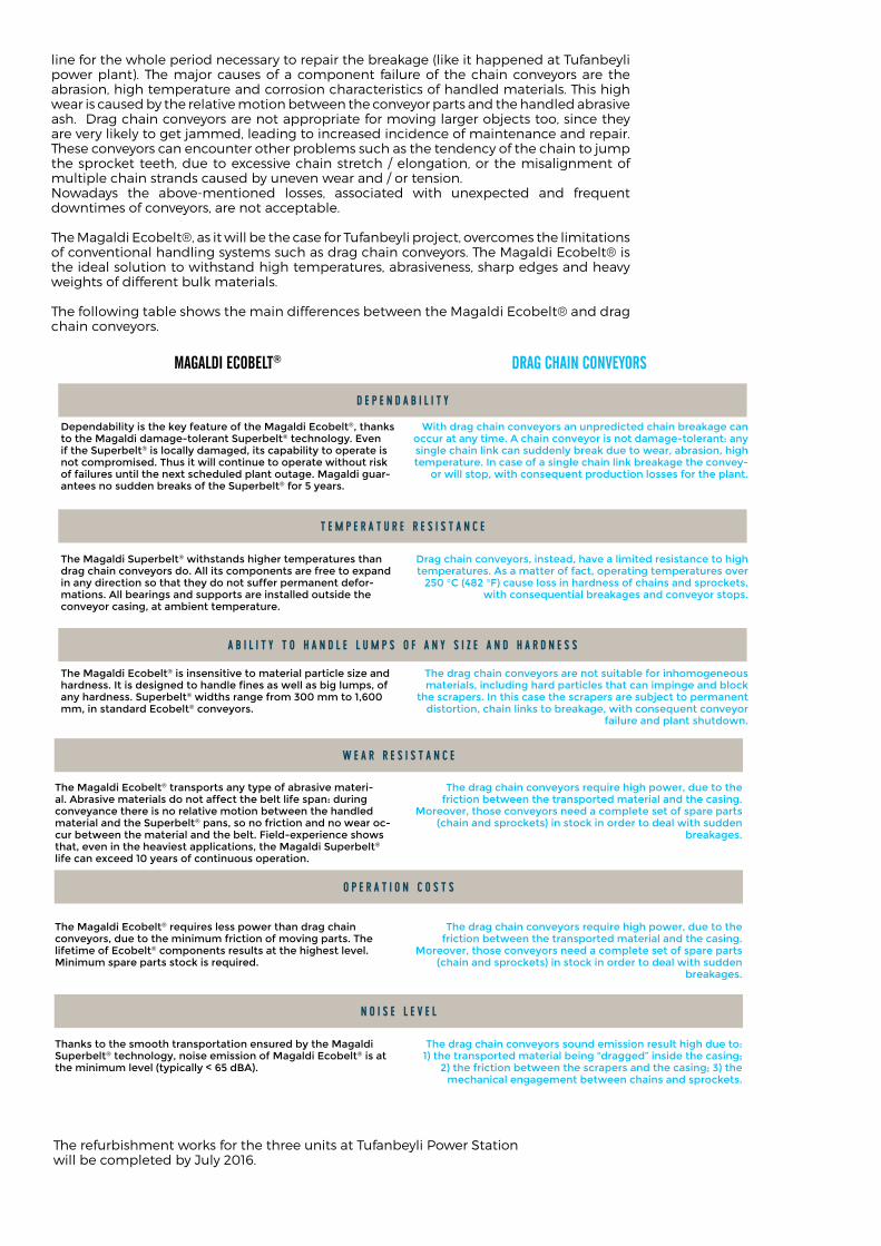
The following table shows the main differences between the magaldi ecobelt® and drag chain conveyors.
The refurbishment works for the three units at Tufanbeyli Power station will be completed by July 2016.
dependability is the key feature of the Magaldi ecobelt®, thanks to the Magaldi damage-tolerant superbelt® technology. even if the superbelt® is locally damaged, its capability to operate is not compromised. thus it will continue to operate without risk of failures until the next scheduled plant outage. Magaldi guar-antees no sudden breaks of the superbelt® for 5 years.
the Magaldi superbelt® withstands higher temperatures than drag chain conveyors do. all its components are free to expand in any direction so that they do not suffer permanent defor-mations. all bearings and supports are installed outside the conveyor casing, at ambient temperature.
the Magaldi ecobelt® is insensitive to material particle size and hardness. It is designed to handle fines as well as big lumps, of any hardness. superbelt® widths range from 300 mm to 1,600 mm, in standard ecobelt® conveyors.
Magaldi EcobElt® drag chaiN coNvEyorS
with drag chain conveyors an unpredicted chain breakage can occur at any time. a chain conveyor is not damage-tolerant: any single chain link can suddenly break due to wear, abrasion, high temperature. in case of a single chain link breakage the convey-
or will stop, with consequent production losses for the plant.
drag chain conveyors, instead, have a limited resistance to high temperatures. as a matter of fact, operating temperatures over
250 °C (482 °f) cause loss in hardness of chains and sprockets, with consequential breakages and conveyor stops.
the drag chain conveyors are not suitable for inhomogeneous materials, including hard particles that can impinge and block
the scrapers. in this case the scrapers are subject to permanent distortion, chain links to breakage, with consequent conveyor
failure and plant shutdown.
D e p e n D a b i l i t y
t e m p e r a t u r e r e s i s t a n c e
a b i l i t y t o h a n D l e l u m p s o f a n y s i z e a n D h a r D n e s s
the Magaldi ecobelt® transports any type of abrasive materi-al. abrasive materials do not affect the belt life span: during conveyance there is no relative motion between the handled material and the superbelt® pans, so no friction and no wear oc-cur between the material and the belt. field-experience shows that, even in the heaviest applications, the Magaldi superbelt® life can exceed 10 years of continuous operation.
the Magaldi ecobelt® requires less power than drag chain conveyors, due to the minimum friction of moving parts. the lifetime of ecobelt® components results at the highest level. Minimum spare parts stock is required.
thanks to the smooth transportation ensured by the Magaldi superbelt® technology, noise emission of Magaldi ecobelt® is at the minimum level (typically < 65 dba).
the drag chain conveyors require high power, due to the friction between the transported material and the casing.
Moreover, those conveyors need a complete set of spare parts (chain and sprockets) in stock in order to deal with sudden
breakages.
the drag chain conveyors sound emission result high due to: 1) the transported material being “dragged” inside the casing;
2) the friction between the scrapers and the casing; 3) the mechanical engagement between chains and sprockets.
o p e r a t i o n c o s t s
n o i s e l e v e l
the drag chain conveyors require high power, due to the friction between the transported material and the casing.
Moreover, those conveyors need a complete set of spare parts (chain and sprockets) in stock in order to deal with sudden
breakages.
W e a r r e s i s t a n c e

ECOBELT® FACONVEYOR #2
CRUSHING TOWER
MAC® EXTRACTOR
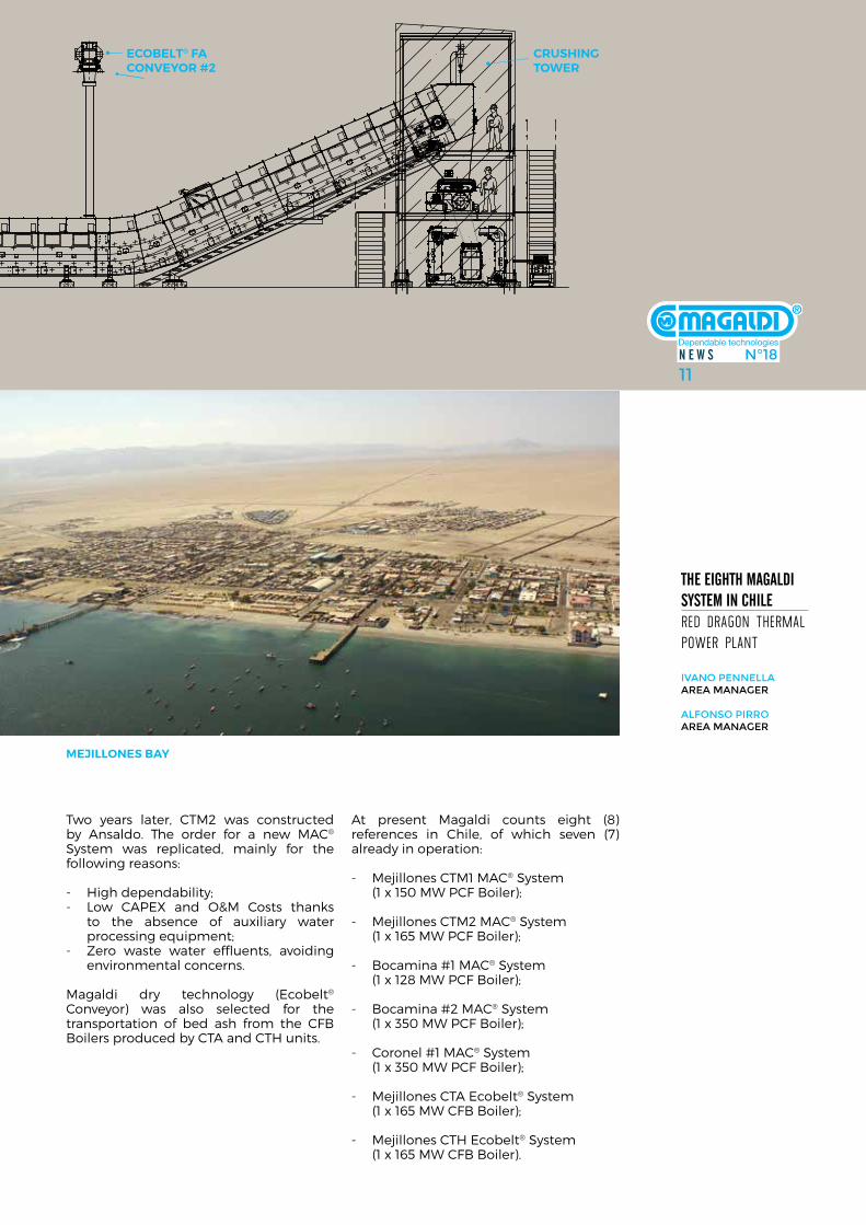
thE Eighth Magaldi SyStEM iN chilE red dragon Thermal power planTthe trust on MagalDi reliable anD well proven technologies has brought sK e&c to awarD the first contract to MagalDi power for the bottoM & econoMizer ash hanDling systeM at reD Dragon (pieM) therMal power magaldi Power s.p.a. has been awarded from sk e&c with an order for the design and supply of the mac® (figure 1) & ecobelt® fa (figure 2) systems for the unit #7 of red dragon (Piem) Thermal Power Plant in chile. chile is one of the most active and modern countries in south america where there is a need for increased and stable sources of energy and with a growing concern over the environmental load that energy production infrastructures could mean to the country. environmental regulations context is therefore always asking for stricter requirements from energy utilities in order to reduce the polluting load from power plants effluents. To cope with such new environmental requirements the mac® & ecobelt® fa technologies have been selected for the Piem Project, wishing to generate clean energy with the most efficient and reliable technology available. The Piem Project comprises of two (2) thermal units (#6 & 7) based on a Pulverized coal-fired (Pc) Boilers, including a selective catalytic reduction (scr) and a flue Gas desulphurization (fGd), each one designed for a gross electrical output of 375 mW at nominal load.
unit #7 will be installed and commissioned first, while unit #6 is an option and will follow in the near future. The new unit will be built on the existing mejillones power plant site, owned by e-cl (former edelnor - subsidiary of french company enGie), which already counts 5 units in operation cTm1 (1 x 150 mW Pc Boiler), cTm2 (1 x 165 mW Pc Boiler), cTm3 (1 x 250 mW ccPP), cTa & cTh (2 x 165 mW cfB Boilers). The site is located on the mejillones Bay of the south Pacific ocean in the chilean Province of antofagasta in a desert-like area (atacama desert) with high seismicity. atacama desert is one of the world’s driest places, which hasn’t seen a drop of rain since hundreds of years. all the water for e-cl’s power plant comes from a costly sea water desalination plant.
in 1994 Babcock & Wilcox española were responsible for the supply of boiler and ash handling system of cTm1. at that time they decided to adopt the mac® system dry technology instead of installing the specified conventional wet submerged chain conveyor, in order to reduce the overall power plant water consumption. cTm1 was the first mac® system installation in chile.
FiGure 1a
N E W S N°1811
ECOBELT® FACONVEYOR #2
CRUSHING TOWER
MAC® EXTRACTOR
thE Eighth Magaldi SyStEM iN chilE red dragon Thermal power planT ivaNo PeNNellaarea MaNager
alfoNso Pirroarea MaNager
Two years later, cTm2 was constructed by ansaldo. The order for a new mac® system was replicated, mainly for the following reasons:
- high dependability;- low caPeX and o&m costs thanks
to the absence of auxiliary water processing equipment;
- Zero waste water effluents, avoiding environmental concerns.
magaldi dry technology (ecobelt® conveyor) was also selected for the transportation of bed ash from the cfB Boilers produced by cTa and cTh units.
at present magaldi counts eight (8) references in chile, of which seven (7) already in operation:
- mejillones cTm1 mac® system (1 x 150 mW Pcf Boiler);
- mejillones cTm2 mac® system (1 x 165 mW Pcf Boiler);
- Bocamina #1 mac® system (1 x 128 mW Pcf Boiler);
- Bocamina #2 mac® system (1 x 350 mW Pcf Boiler);
- coronel #1 mac® system (1 x 350 mW Pcf Boiler);
- mejillones cTa ecobelt® system (1 x 165 mW cfB Boiler);
- mejillones cTh ecobelt® system (1 x 165 mW cfB Boiler).
N E W S N°1811
MeJillones Bay
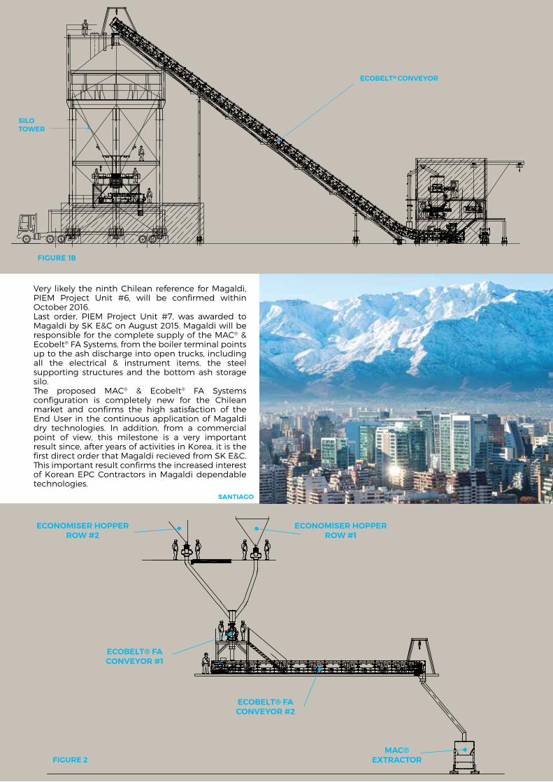
Very likely the ninth chilean reference for magaldi, Piem Project unit #6, will be confirmed within october 2016. last order, Piem Project unit #7, was awarded to magaldi by sk e&c on august 2015. magaldi will be responsible for the complete supply of the mac® & ecobelt® fa systems, from the boiler terminal points up to the ash discharge into open trucks, including all the electrical & instrument items, the steel supporting structures and the bottom ash storage silo.The proposed mac® & ecobelt® fa systems configuration is completely new for the chilean market and confirms the high satisfaction of the end user in the continuous application of magaldi dry technologies. in addition, from a commercial point of view, this milestone is a very important result since, after years of activities in korea, it is the first direct order that magaldi recieved from sk e&c. This important result confirms the increased interest of korean ePc contractors in magaldi dependable technologies.
ECONOMISER HOPPERROW #2
ECOBELT® FACONVEYOR #1
ECOBELT® FACONVEYOR #2
MAC®EXTRACTOR
ECONOMISER HOPPERROW #1
ECOBELT@ CONVEYOR
SILOTOWER
sanTiaGo
FiGure 2
figure 1b
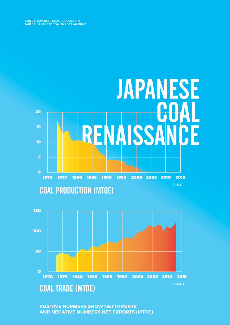
N E W S N°1813JapaNESE
coal rENaiSSaNcE
table 1: JaPaNese Coal ProduCtioN table 2: JaPaNese Coal iMPort aMouNt
table 1
table 2

nowadays Japan, together with china, us and india, accounts for three quarters of global coal consumption. in 2002 Japanese coal production came to an end, and ever since the country has been totally reliant on importation. Japan, korea, india and china, are noticeably the largest coal net importers (together accounting for 56% of world coal imports).in early 2011, 30% of the Japan’s total electricity production (47.5 GWe of net capacity) was generated by nuclear power plants and there were plans to increase it to 41% by 2017, and 50% by 2030. nuclear energy was a national strategic priority in Japan.however, following the fukushima daiichi nuclear disaster, happened on 11 march 2011 due to the tsunami generated
by one of the biggest undersea earthquake, the government sought to greatly reduce the role of nuclear power. all the Japan’s nuclear power plants were progressively shut down for safety concerns and in 2014 Japan generated 1,025 TWh gross, 337 TWh from coal and nothing from nuclear (whilst 288 TWh were generated in 2010). in response to this nuclear crisis fossil fuel consumption increased and led to a wave of new green coal plants construction. it is planned to increase coal capacity up to 47 GW by early 2020s (36 GW at the end of 2013). Japan plans to build more than 30 new green coal-fired power generation units in the next decade or so. some projects are on-going while others are still under the Government approval. in this context, magaldi Power s.p.a. along with its Japanese licensee,
kawasaki heavy industries (khi), has strong intention to take part in this ambitious plan. magaldi is a pioneer of the eco-friendly technologies, introducing the dry bottom ash handling system (mac® system) in solid-fuel power plants early in 1985. magaldi dry technology - able to handle, cool and transport bottom ash from boilers without the usage of any drop of water - eliminates all water related problems, thus complying with the most stringent Japanese environmental regulations and ensuring the continuous operation of the plant without any problem. since 1994 khi recognized the high performances of mac® system, thanks to the superbelt® design that ensures continuous ash removal, low wear, low power demand, long service-life, low o&m costs and safe operations. moreover, the possibility to increase the boiler efficiency reducing the coal consumption, the auxiliary energy consumption, the co2 emissions, and to eliminate the ash ponds and its relevant environmental impact were of high interest and in line with the demanding Japanese standards. from 1999 to 2006 khi succeeded in installing seven mac® systems in the most advanced Japanese power stations.nowadays the dry bottom ash technology has been fully recognized in Japan and is one of clients’ preferred solutions to be applied for the green coal fired power plants in order to mitigate the environmental impact of coal generated power. in 2013, before starting the official bids for the new thermal power plants, magaldi and khi had already shared all information relevant to the mac® system technical features in order to optimize its configuration and provide the best solution to all Japanese clients. The mac® systems configuration has been designed according to the state of the art in order to meet the Japanese standards. most of them will have the following configuration: mechanical expansion joints, bottom ash hopper equipped with hydraulic bottom doors, mac® extractor, crushing stage with hydraulic pre-crusher and single roll primary crusher, ecobelt® conveyor equipped with o-chain®, further bottom ash size reduction by means of vibrating rod mills, Ba storage silo and pneumatic transportation to fly ash silo. in less than one year (from april 2015 to march 2016), magaldi along with kawasaki, has been awarded with four orders for the supply of total five mac® systems plus an engineering
contract that within a year will be converted into an order for the supply of another mac® system. some of those orders represent a further confirmation of the customers’ confidence in magaldi patented technologies since the mac® systems had been already installed in their power stations, while others represent a new achievement because the mac® system will be installed in power stations where conventional wet systems have been applied to the existing units.
figure 1: New MaC® systeM tyPiCal CoNfiguratioN for JaPaNese Market
soMetiMes coal is calleD the fuel of the past, actually, coal is also the fuel of toDay. global coal proDuction in 2013 was 2.8 tiMes larger than in 1973 anD 75% larger than it was in 2000. coal still accounts for 29% of the worlD total energy supply, while its share is even higher (41%) in terMs of electricity proDuction.
1 Hitachinaka #3 650 PCF Boiler Coal 5.9 11.8 Greenfield 10/2020
2 Kashima #2 645 PCF Boiler Coal 4.7 9.4 Greenfield 6/2020
3 Noshiro #3 600 PCF Boiler Coal 4.5 9 Greenfield 6/2020
4 Shinko Kobe #3 650 PCF Boiler Coal 3.18 4.77 Greenfield 10/2021
5 Shinko Kobe #4 650 PCF Boiler Coal 3.18 4.77 Greenfield 10/2022
6 Takehara #1 600 PCF Boiler Coal 8.9 20.9 Greenfield 9/2020
NorMal bottoM aSh ratE [t/h]
Max bottoM aSh ratE
[t/h]
proJEct typEFuEl codcoMbuStioN
SyStEM
uNit SiZE [MW]
plaNt / uNitNo
N E W S N°1815
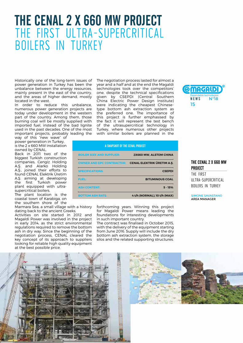
historically one of the long-term issues of power generation in Turkey has been the unbalance between the energy resources, mainly present in the east of the country, and the areas of higher demand, mostly located in the west. in order to reduce this unbalance, numerous power generation projects are today under development in the western part of the country. among them, those burning coal will be mostly supplied with imported fuel, instead of the bad lignite used in the past decades. one of the most important projects, probably leading the way of this “new wave” of power generation in Turkey, is the 2 x 660 mW installation owned by cenal. Back in 2011 two of the biggest Turkish construction companies, cengiz holding a.Ş. and alarko holding a.Ş., joined their efforts to found cenal elektrik Üretim a.Ş. aiming at developing the first Turkish power plant equipped with ultra-supercritical boilers.The plant location is the coastal town of karabiga, on the southern shore of the marmara sea, a small village with a history dating back to the ancient Greeks. activities on site started in 2012 and magaldi Power was involved in the project in early 2014, as the strict environmental regulations required to remove the bottom ash in dry way. since the beginning of the negotiation process, cenal cleared the key concept of its approach to suppliers looking for reliable high quality equipment at the best possible price.
The negotiation process lasted for almost a year and a half and at the end the magaldi technologies took over the competitors’ one, despite the technical specifications given by csePdi (central southern china electric Power design institute) were indicating the cheapest chinese-type bottom ash extraction system as the preferred one. The importance of this project is further emphasised by the fact it will represent the test bench of the ultrasupercritical technology in Turkey, where numerous other projects with similar boilers are planned in the
forthcoming years. Winning this project for magaldi Power means leading the foundations for interesting developments in such important country. The contract was finalised in october 2015, with the delivery of the equipment starting from June 2016. supply will include the dry bottom ash extraction system, the storage silos and the related supporting structures.
thE cENal 2 x 660 MW proJEctThe firsT ulTra-supercriTical boilers in Turkey
thE cENal 2 x 660 MW proJEctThe firsT ulTra-supercriTical boilers in Turkey
siMoNe savastaNoarea MaNager
Boiler siZe and supplier: 2x660 MW, alsToM china
oWner and epc conTracTor: cenal elekTrik ÜreTiM a.Ş.
speciFicaTions: csepdi
Fuel: BiTuMinous coal
ash conTenT: 5 - 15%
BoTToM ash raTe: 4 t/h (norMal), 10 t/h (Max)
a SNapShot oF thE cENal proJEct
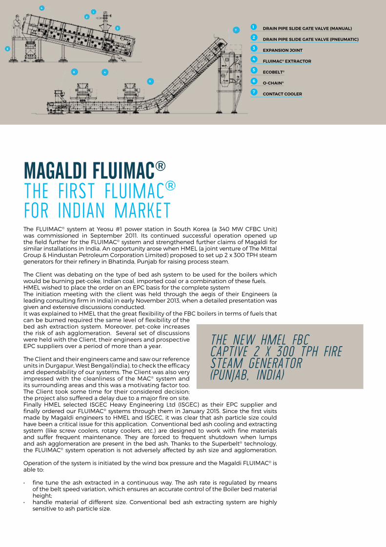
Magaldi FluiMac®
The firsT fluimac® for indian markeT The fluimac® system at Yeosu #1 power station in south korea (a 340 mW cfBc unit) was commissioned in september 2011. its continued successful operation opened up the field further for the fluimac® system and strengthened further claims of magaldi for similar installations in india. an opportunity arose when hmel (a joint venture of The mittal Group & hindustan Petroleum corporation limited) proposed to set up 2 x 300 TPh steam generators for their refinery in Bhatinda, Punjab for raising process steam.
The client was debating on the type of bed ash system to be used for the boilers which would be burning pet-coke, indian coal, imported coal or a combination of these fuels.hmel wished to place the order on an ePc basis for the complete system The initiation meeting with the client was held through the aegis of their engineers (a leading consulting firm in india) in early november 2013, when a detailed presentation was given and extensive discussions conducted. it was explained to hmel that the great flexibility of the fBc boilers in terms of fuels that can be burned required the same level of flexibility of the bed ash extraction system. moreover, pet-coke increases the risk of ash agglomeration. several set of discussions were held with the client, their engineers and prospective ePc suppliers over a period of more than a year.
The client and their engineers came and saw our reference units in durgapur, West Bengal(india), to check the efficacy and dependability of our systems. The client was also very impressed with the cleanliness of the mac® system and its surrounding areas and this was a motivating factor too. The client took some time for their considered decision; the project also suffered a delay due to a major fire on site.finally hmel selected isGec heavy engineering ltd (isGec) as their ePc supplier and finally ordered our fluimac® systems through them in January 2015. since the first visits made by magaldi engineers to hmel and isGec, it was clear that ash particle size could have been a critical issue for this application. conventional bed ash cooling and extracting system (like screw coolers, rotary coolers, etc.) are designed to work with fine materials and suffer frequent maintenance. They are forced to frequent shutdown when lumps and ash agglomeration are present in the bed ash. Thanks to the superbelt® technology, the fluimac® system operation is not adversely affected by ash size and agglomeration.
operation of the system is initiated by the wind box pressure and the magaldi fluimac® is able to:
• fine tunetheashextracted inacontinuousway.Theash rate is regulatedbymeans of the belt speed variation, which ensures an accurate control of the Boiler bed material height;
• handlematerial of different size. Conventional bed ash extracting systemare highlysensitive to ash particle size.
6 4
7
5
1
2
3
4
5
1 drain pipe slide GaTe valve (Manual)
2 drain pipe slide GaTe valve (pneuMaTic)
3 expansion JoinT
4 FluiMac® exTracTor
5 ecoBelT®
6 o-chain®
7 conTacT cooler
the new hMel fbc captive 2 x 300 tph fire steaM generator (punjab, inDia)
N E W S N°1817
Magaldi FluiMac®
The firsT fluimac® for indian markeT
debasish ChakrabertyMagaldi Power iNdia Pvt. ltd. CouNtry MaNager
MiChele Corradosales teaM leader Power divisioN
loreNzo lePore ProCess eNgiNeer
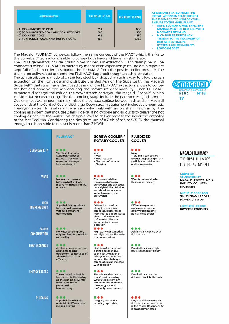
opEratiNg coNditioN
(a) 100 % iMPorted Coal 2.4 600(b) 70 % iMPorted Coal aNd 30% Pet-Coke 3.0 750(C) 100 % Pet-Coke 6.3 1,550(d) 70 % iNdiaN Coal aNd 30% Pet-Coke 8.7 2,150
total bEd aSh ratE [t/h] hEat rEcovEry [kWth]
The magaldi fluimac® conveyors follow the same concept of the mac® which, thanks to the superbelt® technology, is able to convey both fines and larger agglomerate.The hmel generators include 2 drain pipes for bed ash extraction. each drain pipe will be connected to one fluimac® extractors by means of an expansion joint. The drain pipes are kept full of ash in order to separate the fluimac® from the positive boiler pressure. The drain pipe delivers bed ash onto the fluimac® superbelt trough an ash distributor. The ash distributor is made of a stainless steel box shaped in such a way to allow the ash extraction on the front side and distribute the Bed ash on the superbelt®. The magaldi superbelt®, that runs inside the closed casing of the fluimac® extractors, allows to convey the hot and abrasive bed ash ensuring the maximum dependability. Both fluimac® extractors discharge the ash on the downstream conveyor, the magaldi ecobelt®, which provides further ash cooling. The final cooling stage include the patented magaldi contact cooler a heat exchanger that maximizes the contact surface between ash and air. magaldi scope ends at the contact cooler discharge. downstream equipment includes a pneumatic conveying system to final silo. The ash is cooled only with ambient air drawn in by the cooling air system that includes 2 fans, 1 de-dusting cyclone and air ducts to deliver the hot cooling air back to the boiler. This design allows to deliver back to the boiler the enthalpy of the hot Bed ash. considering the design values of 8,7 t/h of ash at 925 °c, the thermal energy that is possible to recover is more than 2 mWth.
FluiMac® screW cooler / roTary cooler
dEpENdability very high thanks to superbelt® concept (no wear, free thermal expansion, damage tolerant design)
low: - wear - water leakage - thermal deformation- Plugging
low:- plugging can be very frequent depending on ash particle size distribution and homogeneity
FluidiZed cooler
WEar No relative movement between belt and ash means no friction and thus no wear
Continuous relative movement between screw/shell and ash cause very high friction. friction and abrasion can cause water leakage in the screw/shell
wear is present due to fluidised air velocity
high tEMpEraturES
superbelt® design allows free thermal expansion without permanent deformations
different expansion along the cooler (ash temperature decreases from inlet to outlet) causes stress and permanent deformation that can compromise system operation
different expansions can cause stress and deformation in some points of the cooler
WatEr coNSuMptioN
No water consumption, only ambient air is used for ash cooling
high water consumption and high cost for the water treatment system
ash is mainly cooled with fluidized air
hEat ExchaNgE Air flow proper design and additional cooling equipment (contact cooler) allow to increase the efficiency
heat transfer reduction during operation due to the accumulation of ash layers on the screw surface. the discharge temperature can increase with operation
fluidization allows high heat exchange efficiency
ENErgy loSSES the ash sensible heat is transferred to the cooling air that can be delivered back to the boiler performed heat recovery
the ash sensible heat is transferred to cooling water at relatively low temperatures, therefore the energy cannot profitably be recovered.
fluidization air can be delivered back to the boiler
pluggiNg superbelt® can handle material of different size including lumps
Plugging and screw jamming is possible
large particles cannot be fluidized and accumulates in the cooler. dependability is drastically affected
as deMonsTraTed FroM The insTallaTions in souTh korea, The FluiMac® TechnoloGy Will ensure To The hMel planT:- saFe, econoMic and eFFicienT
ManaGeMenT oF Bed ash WiTh no WaTer deMand,
- hiGh Boiler eFFiciency Thanks To The recovery oF Bed ash enThalpy,
- sysTeM hiGh reliaBiliTy,- loW o&M cosT.
Elg For aSh traNSport WatEreffluenT limiTaTion guidelinesThe united states environmental Protection agency (ePa), on september 30, 2015, finalized a rule revising the regulations for the steam electric power generating category. This set the first federal limits on the level of toxic metals in waste water that can be discharged from power plants. The final rule sets new or additional requirements for waste water streams from the following processes:
- Flue Gas desulFuriZaTion- Fly ash and BoTToM ash- Flue Gas Mercury conTrol- GasiFicaTion oF Fuels such as - coal and peTroleuM coke
The ePa’s preferred options for all models will require zero discharge of flyash and bottom ash transport water on units larger than 50 mW. federal compliance schedule for the effluent limitation Guidelines are asaP or starting nov. 1st, 2018 and no later than dec. 31st 2013. each individual plant’s compliance schedule is determined through national Pollutant discharge elimination system (nPdes) permit system.
lisTed BeloW are The WeT sysTeM closed loop opTions For elG BoTToM ash coMpliance opTions
OptiOn 1. Submerged Scraper cOnveyOr (SSc) under bOiler equipment.
There needs to be clarification regarding a retrofit ssc, a remote ssc or dewatering bins as a “Wet to dry” conversion option. These systems still use water to quench or transport ash. The caveat is that ash quench water currently is not specified as an elG waste water stream. But like all ePa regulations it’s just a matter of time before quench water (because it comes in direct contact with ash and removes a large amount of suspended ash particulate) will fall under the waste water stream known as ash transport water. underneath the boiler ssc retrofits may have several limiting factors. a ssc requires unencumbered physical space under the boiler and a free corridor for the dewatering ramp. The location of obstacles such as boiler downcomers, pulverisers and boiler support structures limit an ssc as a retrofit option.
OptiOn 2. dewatering bin SyStemS
dewatering bins (setup to work in pairs) are used in conjunction with a traditional water impounded bottom ash hopper and high pressure water conveying system. existing dewatering bins have been used as part of a closed loop ash water system. The key to the dewatering bins are the dewatering screens. These screens are very susceptible to blinding due to water chemistry and ash fines. most bins have some type of screen cleaning system which includes high pressure water jet nozzles. To be noted dewatering bin built in screen cleaning nozzles will not remove scale buildup. due to the design of the bins (tall and cylindrical) most maintenance requires substantial labor. also dewatering bin discharge gates are under a heavy load and leak continuously when the bins are in operation. dewatering bins hold an extremely large quantity of ash
water and any closed loop ash water recirculation system will have to be designed to accommodate these large quantities.
OptiOn 3. remOte SScS fOr dewatering and clOSed lOOp water recirculatiOn.
considered as mechanical dewatering bins. This type of system retains the existing old style high maintenance water impounded bottom ash hopper and high pressure water conveying system. remote sscs like dewatering bins are supplied in pairs and are additional pieces of capital equipment installed to bypass the ash pond. To date very few sscs have been installed as a remote solution for dewatering and removing suspended solids. it’s too early for an overall evaluation of operational information. however, at a minimum all of the operation and maintenance issues with a closed loop water recirculation system will apply to remote sscs. The following bullet points should be included when evaluating remote sscs or any Wet ash handling system for elG ash transport water decisions.
• Reliability,abrasivewear,watertreatmentcapabilitiesand reintroduction of ash into the Water impounded Bottom ash hopper supply manifolds and seal trough.
• AdditionalO&MbudgetdollarsfortheremoteSSCsand closed loop water handling / treatment equipment will have to be added to the current o&m budget.
• Reroutingthebottomashpitsumpintothenewclosedloop recirculation system.
• OnlinerepairwhenSSCsarefullofashandashtransportwater.
• Overflowcatchbasinsandpumpsystemstokeeptheash transport water in the recirculation system.
• Coaladditiveeffectsonwaterchemistry.• Scalingoncomponentsandscreenblinding• IncreasingwaterpH,acommonclosedlooprecirculation
ash water system issue.• Suspended Solids carry over and deposited back into
the bottom ash hopper water supply manifolds.• Design and implementation of a closed loop water
system, conveying distance, pump selection, system sizing and redundancy of major components.
traditiOnal wet bOttOm aSh SyStem nOteS
average water usage on a 500 mW Powder river Basin (PrB)1 fired Pc boiler with a traditional water impounded bottom ash hopper and ash sluice system.
conTinuous WaTer FloWseal TrouGh 50 GPm (3.15 l/s) Wall coolinG 108 GPm (6.81 l/s) make uP 389 GPm (24.54 l/s) ToTal conTinuous FloW 547 GpM = 787,680 Gpday (3,000 MeTric Tons per day)
N E W S N°1819
Elg For aSh traNSport WatEreffluenT limiTaTion guidelines
keith holtMagaldi teChNologies llC sales area MaNager daNiele CoPPola area MaNager
1 Powder river Basin coal is classified as “sub-bituminous” and contains an average of approximately 8,500 btu/lb (around 20 mJ/kg), with low so2. contrast this with eastern, appalachian bituminous coal containing an average of 12,500 btu/lb (29 mj/kg) and high so2. PrB coal was essentially worthless until air pollution emissions from power
addiTional WaTer FloW When flushinG and TransPorTinG.seal trough 580 GPm (36.59 l/s) conveying 1,060GPm (66.88 l/s). Total flushing and transport 1,640 GPm x 15 min. X 6 cycles per day = 147,600 GPday (560 metri tons per day)ToTal WaTer usaGe 935,280 Gpday =650 GpM (3.5 Millions oF liTres per day)
ssc WeT BoTToM ash sysTeMmake up water, 8 TPh x 20% = 3,200 PPh of water (Weight of 1 us Gallon of water = approx. 8.35 lb.) = 383 Gph WaTer conveyed ouT oF The sysTeM.cooling water, 200 GPm x 60 = 12,000 GPhToTal WaTer usaGe 296,640 Gpday = 206 GpM (>1 Million liTres per day)
lisTed BeloW is The MaGaldi dry sysTeM opTion For elG BoTToM
ash coMpliance opTions. The phrase “wet to dry” conversion means you eliminate 100% of water from a traditional old technology water impounded bottom ash hopper / sluice system. The paradigm shift for the coal power industry is to convert to a dry bottom ash transport system. This conversion will eliminate the need for a closed loop water system and all of its associated water containment issues.
The magaldi ash cooler (mac®) is a unique patented machine and designed for 100% dry ash conveying. using only ambient air instead of water for bottom ash cooling and handling. The “mac®” is a true wet to dry conversion option that has been used throughout the world at approximately 200 locations. The “mac®” system overcomes the burden of higher capex and opex encountered when attempting to make a traditional wet ash system conform under the elG guidelines. all water related problems associated with dewatering bins, sscs and remote sscs including waste water treatment, pumps, heat exchangers, increasing ph, water chemistry do not exist with a “mac®” superbelt dry ash cooling system. magaldi’s “mac®” system has been proven over the last 30 years to be the world’s
most reliable bottom ash system with the lowest o&m costs of any other wet or dry ash system available.
one of the key differences with the magaldi unit is that any object that can pass through the opening between the bottom nose tubes will fall into the magaldi system and be conveyed away. That means there are no pinch points to stop large clinkers, tube shields or soot blower lances and which can cause a forced outage situation.
The “mac®” system provides the benefit of energy recovery from dry bottom ash removal back to the boiler, thus increasing boiler efficiency.
The flexibility of a mac® mechanical bottom ash system makes a retrofit project easier to design. The “mac®” will fit into most location where an ssc will not. depending on the location of the ash silo either a completely mechanical system can be applied or a mechanical to pneumatic system design for carrying the ash long distances. The mac® dry difference is simple and free from all water related issues.
conclusions
The new ccr and elG regulations are causing new challenges to the way coal plants handle and dispose of ash. a fully dry technology hits those challenges head on for bottom ash and will be able to help the power plant meet the regulatory challenges and eliminate any future ash water concerns.
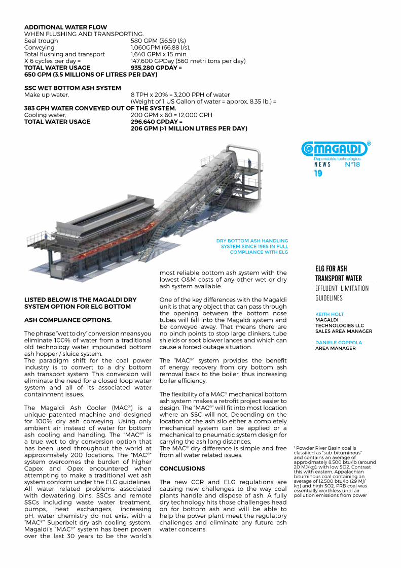
dry bottoM ash haNdliNg systeM siNCe 1985 iN full
CoMPliaNCe with elg
N E W S N°1819
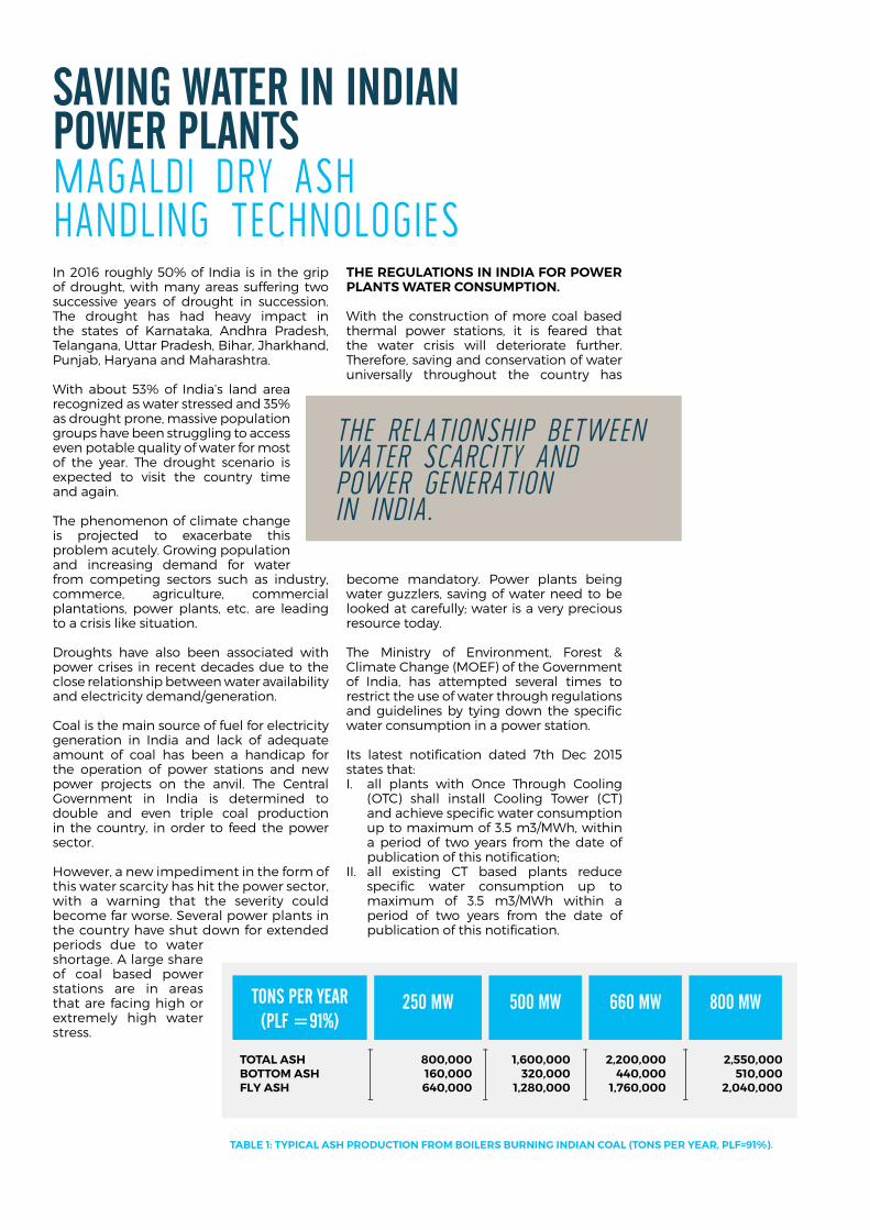
SaviNg WatEr iN iNdiaN poWEr plaNtS magaldi dry ash handling Technologies in 2016 roughly 50% of india is in the grip of drought, with many areas suffering two successive years of drought in succession. The drought has had heavy impact in the states of karnataka, andhra Pradesh, Telangana, uttar Pradesh, Bihar, Jharkhand, Punjab, haryana and maharashtra.
With about 53% of india’s land area recognized as water stressed and 35% as drought prone, massive population groups have been struggling to access even potable quality of water for most of the year. The drought scenario is expected to visit the country time and again.
The phenomenon of climate change is projected to exacerbate this problem acutely. Growing population and increasing demand for water from competing sectors such as industry, commerce, agriculture, commercial plantations, power plants, etc. are leading to a crisis like situation.
droughts have also been associated with power crises in recent decades due to the close relationship between water availability and electricity demand/generation.
coal is the main source of fuel for electricity generation in india and lack of adequate amount of coal has been a handicap for the operation of power stations and new power projects on the anvil. The central Government in india is determined to double and even triple coal production in the country, in order to feed the power sector.
however, a new impediment in the form of this water scarcity has hit the power sector, with a warning that the severity could become far worse. several power plants in the country have shut down for extended periods due to water shortage. a large share of coal based power stations are in areas that are facing high or extremely high water stress.
The reGulaTions in india For poWer planTs WaTer consuMpTion. With the construction of more coal based thermal power stations, it is feared that the water crisis will deteriorate further. Therefore, saving and conservation of water universally throughout the country has
become mandatory. Power plants being water guzzlers, saving of water need to be looked at carefully; water is a very precious resource today.
The ministry of environment, forest & climate change (moef) of the Government of india, has attempted several times to restrict the use of water through regulations and guidelines by tying down the specific water consumption in a power station.
its latest notification dated 7th dec 2015 states that:i. all plants with once Through cooling
(oTc) shall install cooling Tower (cT) and achieve specific water consumption up to maximum of 3.5 m3/mWh, within a period of two years from the date of publication of this notification;
ii. all existing cT based plants reduce specific water consumption up to maximum of 3.5 m3/mWh within a period of two years from the date of publication of this notification.
the relationship between water scarcity anD power generation in inDia.
TaBle 1: Typical ash producTion FroM Boilers BurninG indian coal (Tons per year, plF=91%).
TOTAL ASH 800,000 1,600,000 2,200,000 2,550,000BOTTOM ASH 160,000 320,000 440,000 510,000FLY ASH 640,000 1,280,000 1,760,000 2,040,000
TONS PER YEAR(PLF =91%)
800 MW660 MW500 MW250 MW
N E W S N°1821
HYDRAULIC SEAL
BOTTOM ASH
SUMP
B.A. SLURRY DISPOSALPUMP HOUSE
BOTTOM ASH POND
BOTTOM HOPPER
CRUSHERS
LP PUMP
MAKE UP WATER
WATER RESERVOIR
OVERFLOWWATER
TREATMENT
RECIRCULATIONWATER PUMP
RE
CY
CLE
D W
ATE
R
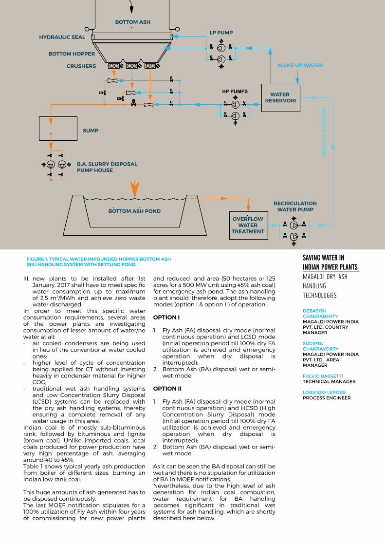
FiGure 1: Typical WaTer iMpounded hopper BoTToM ash (Ba) handlinG sysTeM WiTh seTTlinG pond.
SaviNg WatEr iN iNdiaN poWEr plaNtSmagaldi dry ash handling Technologies
debasish ChakrabertyMagaldi Power iNdia Pvt. ltd. CouNtry MaNager
sudiPto ChakravortyMagaldi Power iNdia Pvt. ltd. area MaNager
fulvio bassettiteChNiCal MaNager
loreNzo lePore ProCess eNgiNeer
iii. new plants to be installed after 1st January, 2017 shall have to meet specific water consumption up to maximum of 2.5 m3/mWh and achieve zero waste water discharged.
in order to meet this specific water consumption requirements, several areas of the power plants are investigating consumption of lesser amount of water/no water at all:• air cooled condensers are being used
in lieu of the conventional water cooled ones;
• higher level of cycle of concentrationbeing applied for cT without investing heavily in condenser material for higher coc;
• traditional wet ash handling systemsand low concentration slurry disposal (lcsd) systems can be replaced with the dry ash handling systems, thereby ensuring a complete removal of any water usage in this area.
indian coal is of mostly sub-bituminous rank, followed by bituminous and lignite (brown coal). unlike imported coals, local coals produced for power production have very high percentage of ash, averaging around 40 to 45%.Table 1 shows typical yearly ash production from boiler of different sizes, burning an indian low rank coal.
This huge amounts of ash generated has to be disposed continuously. The last moef notification stipulates for a 100% utilization of fly ash within four years of commissioning for new power plants
and reduced land area (50 hectares or 125 acres for a 500 mW unit using 45% ash coal) for emergency ash pond. The ash handling plant should, therefore, adopt the following modes (option i & option ii) of operation:
opTion i
1. fly ash (fa) disposal: dry mode (normal continuous operation) and lcsd mode (initial operation period till 100% dry fa utilization is achieved and emergency operation when dry disposal is interrupted);
2. Bottom ash (Ba) disposal: wet or semi-wet mode.
opTion ii
1. fly ash (fa) disposal: dry mode (normal continuous operation) and hcsd (high concentration slurry disposal) mode (initial operation period till 100% dry fa utilization is achieved and emergency operation when dry disposal is interrupted);
2. Bottom ash (Ba) disposal: wet or semi-wet mode.
as it can be seen the Ba disposal can still be wet and there is no stipulation for utilization of Ba in moef notifications. nevertheless, due to the high level of ash generation for indian coal combustion, water requirement for Ba handling becomes significant in traditional wet systems for ash handling, which are shortly described here below.
COAL
DRY FA
WET BA
BOILER
FA HCSDSYSTEM
LOW WATER NEED
FA LANDFILLAREA
BA LCSD SYSTEMHIGH WATER
NEED
BA POND
FA BIN
WIH SLURRYSLUMP
WATER TREATMENT
SYSTEM
WATER/BA 10 20
WA
TER
/BA
10 20
LCSD
ASH FLOW
WATER FLOW
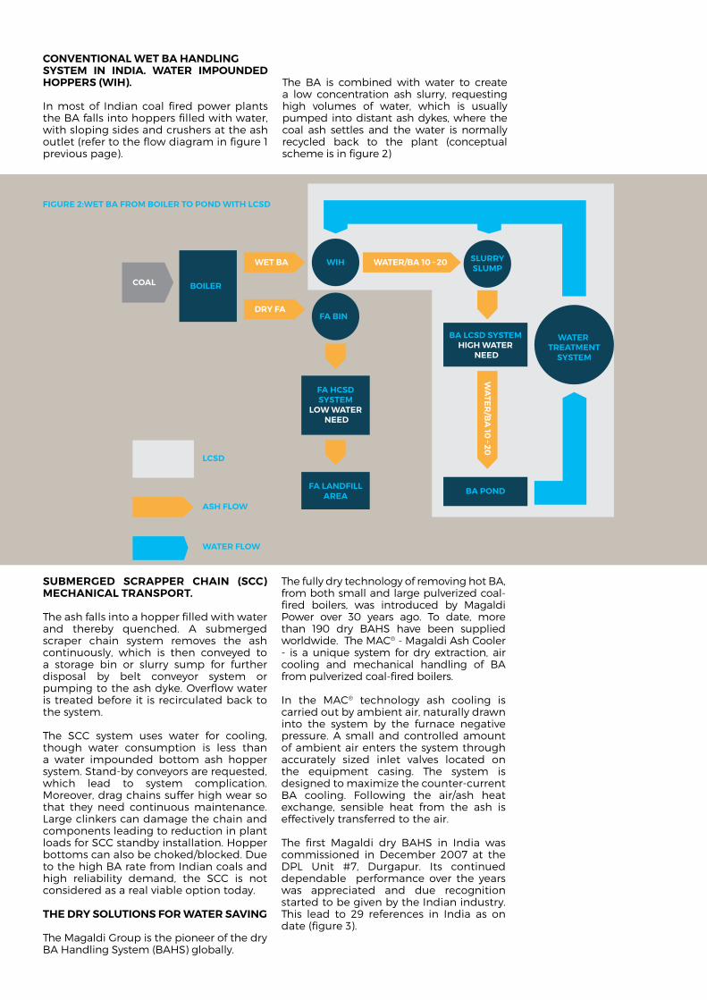
convenTional WeT Ba handlinG sysTeM in india. WaTer iMpounded hoppers (Wih).
in most of indian coal fired power plants the Ba falls into hoppers filled with water, with sloping sides and crushers at the ash outlet (refer to the flow diagram in figure 1 previous page).
The Ba is combined with water to create a low concentration ash slurry, requesting high volumes of water, which is usually pumped into distant ash dykes, where the coal ash settles and the water is normally recycled back to the plant (conceptual scheme is in figure 2)
suBMerGed scrapper chain (scc) Mechanical TransporT.
The ash falls into a hopper filled with water and thereby quenched. a submerged scraper chain system removes the ash continuously, which is then conveyed to a storage bin or slurry sump for further disposal by belt conveyor system or pumping to the ash dyke. overflow water is treated before it is recirculated back to the system.
The scc system uses water for cooling, though water consumption is less than a water impounded bottom ash hopper system. stand-by conveyors are requested, which lead to system complication. moreover, drag chains suffer high wear so that they need continuous maintenance. large clinkers can damage the chain and components leading to reduction in plant loads for scc standby installation. hopper bottoms can also be choked/blocked. due to the high Ba rate from indian coals and high reliability demand, the scc is not considered as a real viable option today.
The dry soluTions For WaTer savinG
The magaldi Group is the pioneer of the dry Ba handling system (Bahs) globally.
The fully dry technology of removing hot Ba, from both small and large pulverized coal-fired boilers, was introduced by magaldi Power over 30 years ago. To date, more than 190 dry Bahs have been supplied worldwide. The mac® - magaldi ash cooler - is a unique system for dry extraction, air cooling and mechanical handling of Ba from pulverized coal-fired boilers.
in the mac® technology ash cooling is carried out by ambient air, naturally drawn into the system by the furnace negative pressure. a small and controlled amount of ambient air enters the system through accurately sized inlet valves located on the equipment casing. The system is designed to maximize the counter-current Ba cooling. following the air/ash heat exchange, sensible heat from the ash is effectively transferred to the air.
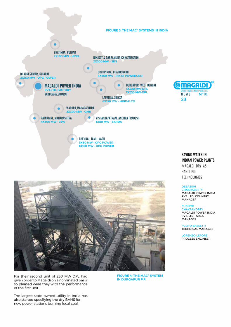
The first magaldi dry Bahs in india was commissioned in december 2007 at the dPl unit #7, durgapur. its continued dependable performance over the years was appreciated and due recognition started to be given by the indian industry. This lead to 29 references in india as on date (figure 3).
FiGure 2:WeT Ba FroM Boiler To pond WiTh lcsd
N E W S N°1823
SaviNg WatEr iN iNdiaN poWEr plaNtSmagaldi dry ash handling Technologies
debasish ChakrabertyMagaldi Power iNdia Pvt. ltd. CouNtry MaNager
sudiPto ChakravortyMagaldi Power iNdia Pvt. ltd. area MaNager
fulvio bassettiteChNiCal MaNager
loreNzo lePore ProCess eNgiNeer
BHADRESHWAR, GUJARAT2X150 MW - OPG POWER
BINJKOT & DARRAMURA,CHHATTISGARH2X300 MW - SKS
UCCHPINDA, CHATTISGARH4X360 MW - R.K.M. POWERGEN
LAPANGA,ORISSA6X150 MW - HINDALCO
WARORA,MAHARASHTRA2X300 MW - GMR
RATNAGIRI, MAHARASHTRA4X300 MW - JSW
CHENNAI, TAMIL NADU3X80 MW - OPG POWER1X160 MW - OPG POWER
VISHAKHAPATNAM, ANDHRA PRADESH1X80 MW - SARDA
DURGAPUR, WEST BENGAL1X300 MW-DPL1X250 MW-DPL
MAGALDI POWER INDIAPVT.LTD. FACTORY
VADODARA,GUJARAT
BHATINDA, PUNJAB2X100 MW - HMEL
FiGure 3: The Mac® sysTeMs in india
for their second unit of 250 mW dPl had given order to magaldi on a nominated basis, so pleased were they with the performance of the first unit.
The largest state owned utility in india has also started specifying the dry Bahs for new power stations burning local coal.
FiGure 4: The Mac® sysTeM in durGapur p.p.
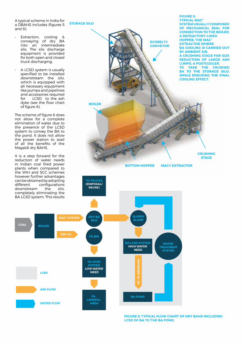
a typical scheme in india for a dBahs includes (figures 5 and 6): • Extraction, cooling &
conveying of dry Ba into an intermediate silo. The silo discharge equipment is provided for both open and closed truck discharging;
• ALCSDsystemisusuallyspecified to be installed downstream the silo, which is equipped with all necessary equipment like pumps and pipelines and accessories required for lcsd to the ash dyke (see the flow chart of figure 6).
The scheme of figure 6 does not allow for a complete elimination of water due to the presence of the lcsd system to convey the Ba to the pond. it does not allow the power station to avail of all the benefits of the magaldi dry Bahs.
it is a step forward for the reduction of water needs in indian coal fired power plants when compared to the Wih and scc schemes however further advantages can be obtained by adopting different configurations downstream the silo, completely eliminating the Ba lcsd system. This results
STORAGE SILO
ECOBELT® CONVEYOR
BOILER
BOTTOM HOPPER MAC® EXTRACTOR
CRUSHINGSTAGE
FiGure 5: Typical Mac® sysTeM usually coMposed oF Mechanical seal For connecTion To The Boiler, a reFracTory-lined hopper, The Mac® exTracTor Where Ba coolinG is carried ouT By aMBienT air, a crushinG sTaGe For siZe reducTion oF larGe ash luMps, a posTcooler, To Take The crushed Ba To The sToraGe silo, While ensurinG The Final coolinG eFFecT.
COAL
DRY FA
MAC® SYSTEM
BOILER
FA HCSDSYSTEM
LOW WATER NEED
TO TRUCKS(DISPOSAL/
REUSE)
FA LANDFILL
AREA
BA LCSD SYSTEMHIGH WATER
NEED
BA POND
FA BIN
DRY BASILO
SLURRYSLUMP
WATER TREATMENT
SYSTEM
WA
TER
/BA
10 20
LCSD
ASH FLOW
WATER FLOW
FiGure 6: Typical FloW charT oF dry Bahs includinG lcsd oF Ba To The Ba pond.
N E W S N°1825
SaviNg WatEr iN iNdiaN poWEr plaNtSmagaldi dry ash handling Technologies
debasish ChakrabertyMagaldi Power iNdia Pvt. ltd. CouNtry MaNager
sudiPto ChakravortyMagaldi Power iNdia Pvt. ltd. area MaNager
fulvio bassettiteChNiCal MaNager
loreNzo lePore ProCess eNgiNeer
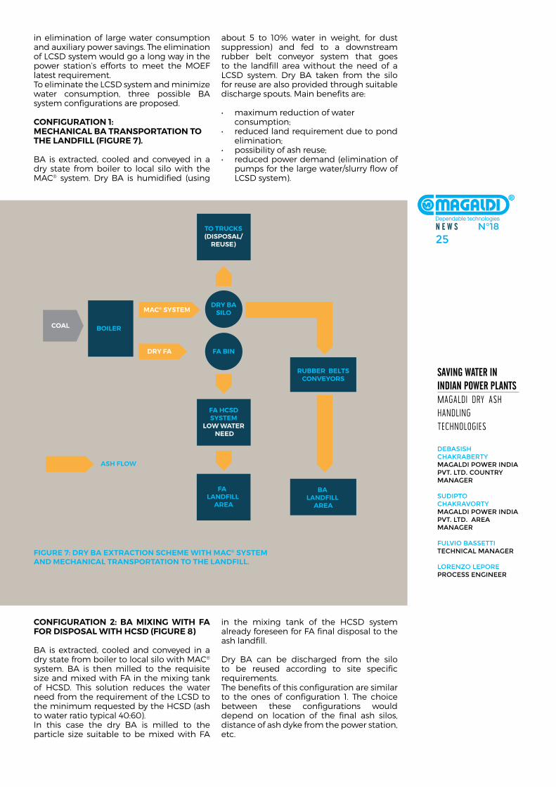
in elimination of large water consumption and auxiliary power savings. The elimination of lcsd system would go a long way in the power station’s efforts to meet the moef latest requirement. To eliminate the lcsd system and minimize water consumption, three possible Ba system configurations are proposed.
conFiGuraTion 1: Mechanical Ba TransporTaTion To The landFill (FiGure 7).
Ba is extracted, cooled and conveyed in a dry state from boiler to local silo with the mac® system. dry Ba is humidified (using
about 5 to 10% water in weight, for dust suppression) and fed to a downstream rubber belt conveyor system that goes to the landfill area without the need of a lcsd system. dry Ba taken from the silo for reuse are also provided through suitable discharge spouts. main benefits are:
• maximumreductionofwater consumption;• reducedlandrequirementduetopond
elimination;• possibilityofashreuse;• reducedpowerdemand(eliminationof
pumps for the large water/slurry flow of lcsd system).
COAL
DRY FA
MAC® SYSTEM
BOILER
FA HCSDSYSTEM
LOW WATER NEED
TO TRUCKS(DISPOSAL/
REUSE)
FA LANDFILL
AREA
RUBBER BELTSCONVEYORS
BA LANDFILL
AREA
FA BIN
DRY BASILO
ASH FLOW
FiGure 7: dry Ba exTracTion scheMe WiTh Mac® sysTeM and Mechanical TransporTaTion To The landFill.
conFiGuraTion 2: Ba MixinG WiTh Fa For disposal WiTh hcsd (FiGure 8)
Ba is extracted, cooled and conveyed in a dry state from boiler to local silo with mac® system. Ba is then milled to the requisite size and mixed with fa in the mixing tank of hcsd. This solution reduces the water need from the requirement of the lcsd to the minimum requested by the hcsd (ash to water ratio typical 40:60).in this case the dry Ba is milled to the particle size suitable to be mixed with fa
in the mixing tank of the hcsd system already foreseen for fa final disposal to the ash landfill.
dry Ba can be discharged from the silo to be reused according to site specific requirements. The benefits of this configuration are similar to the ones of configuration 1. The choice between these configurations would depend on location of the final ash silos, distance of ash dyke from the power station, etc.
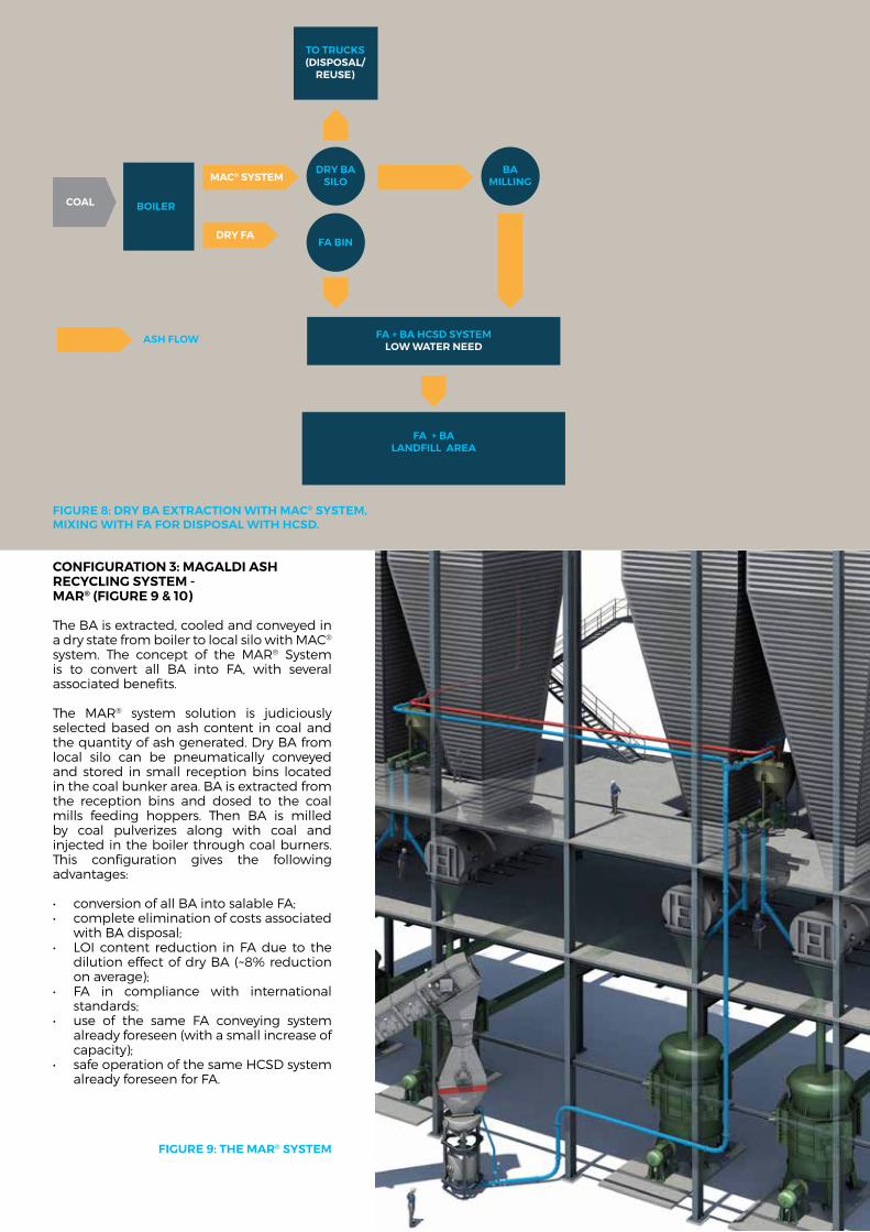
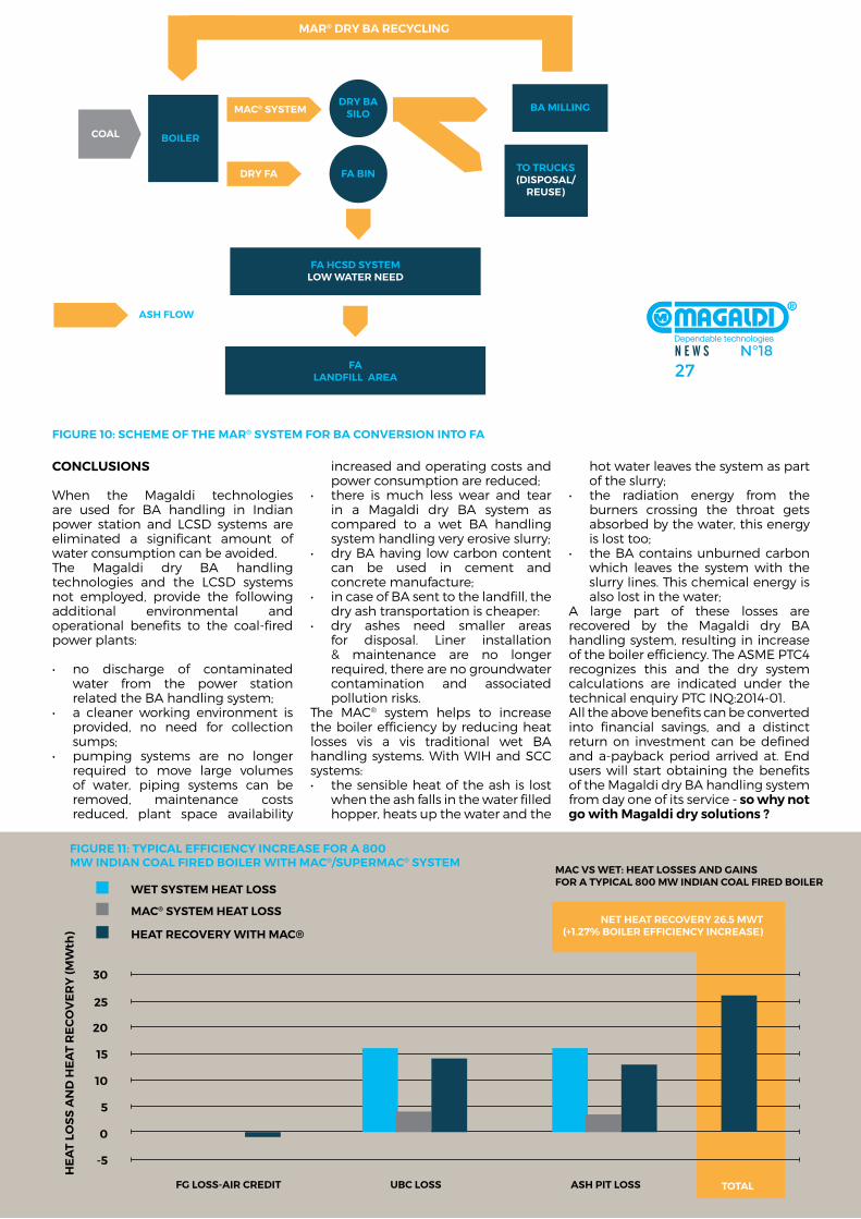
conFiGuraTion 3: MaGaldi ash recyclinG sysTeM - Mar® (FiGure 9 & 10)
The Ba is extracted, cooled and conveyed in a dry state from boiler to local silo with mac® system. The concept of the mar® system is to convert all Ba into fa, with several associated benefits. The mar® system solution is judiciously selected based on ash content in coal and the quantity of ash generated. dry Ba from local silo can be pneumatically conveyed and stored in small reception bins located in the coal bunker area. Ba is extracted from the reception bins and dosed to the coal mills feeding hoppers. Then Ba is milled by coal pulverizes along with coal and injected in the boiler through coal burners. This configuration gives the following advantages:
• conversionofallBAintosalableFA;• completeeliminationofcostsassociated
with Ba disposal;• LOI content reduction inFAdue to the
dilution effect of dry Ba (~8% reduction on average);
• FA in compliance with internationalstandards;
• use of the same FA conveying systemalready foreseen (with a small increase of capacity);
• safeoperationofthesameHCSDsystemalready foreseen for fa.
COAL
DRY FA
MAC® SYSTEM
BOILER
FA + BA HCSD SYSTEMLOW WATER NEED
TO TRUCKS(DISPOSAL/
REUSE)
FA + BALANDFILL AREA
FA BIN
DRY BASILO
BAMILLING
ASH FLOW
FiGure 8: dry Ba exTracTion WiTh Mac® sysTeM, MixinG WiTh Fa For disposal WiTh hcsd.
FiGure 9: The Mar® sysTeM
N E W S N°1827
MAC VS WET: HEAT LOSSES AND GAINSFOR A TYPICAL 800 MW INDIAN COAL FIRED BOILER
FG LOSS-AIR CREDIT UBC LOSS ASH PIT LOSS TOTAL
-5
0
5
10
15
20
25
30
NET HEAT RECOVERY 26.5 MWT(+1.27% BOILER EFFICIENCY INCREASE)
WET SYSTEM HEAT LOSS
MAC® SYSTEM HEAT LOSS
HEAT RECOVERY WITH MAC®
HE
AT
LOS
S A
ND
HE
AT
RE
CO
VE
RY
(MW
th)
COAL
DRY FA
MAC® SYSTEM
BOILER
FA HCSD SYSTEMLOW WATER NEED
BA MILLING
TO TRUCKS(DISPOSAL/
REUSE)
FALANDFILL AREA
FA BIN
DRY BASILO
ASH FLOW
MAR® DRY BA RECYCLING
FiGure 10: scheMe oF The Mar® sysTeM For Ba conversion inTo Fa
conclusions
When the magaldi technologies are used for Ba handling in indian power station and lcsd systems are eliminated a significant amount of water consumption can be avoided. The magaldi dry Ba handling technologies and the lcsd systems not employed, provide the following additional environmental and operational benefits to the coal-fired power plants: • no discharge of contaminated
water from the power station related the Ba handling system;
• a cleaner working environment isprovided, no need for collection sumps;
• pumping systems are no longerrequired to move large volumes of water, piping systems can be removed, maintenance costs reduced, plant space availability
increased and operating costs and power consumption are reduced;
• there is much less wear and tearin a magaldi dry Ba system as compared to a wet Ba handling system handling very erosive slurry;
• dryBAhavinglowcarboncontentcan be used in cement and concrete manufacture;
• incaseofBAsenttothelandfill,thedry ash transportation is cheaper:
• dry ashes need smaller areasfor disposal. liner installation & maintenance are no longer required, there are no groundwater contamination and associated pollution risks.
The mac® system helps to increase the boiler efficiency by reducing heat losses vis a vis traditional wet Ba handling systems. With Wih and scc systems:• thesensibleheatoftheashis lost
when the ash falls in the water filled hopper, heats up the water and the
hot water leaves the system as part of the slurry;
• the radiation energy from theburners crossing the throat gets absorbed by the water, this energy is lost too;
• theBAcontainsunburnedcarbonwhich leaves the system with the slurry lines. This chemical energy is also lost in the water;
a large part of these losses are recovered by the magaldi dry Ba handling system, resulting in increase of the boiler efficiency. The asme PTc4 recognizes this and the dry system calculations are indicated under the technical enquiry PTc inQ:2014-01.all the above benefits can be converted into financial savings, and a distinct return on investment can be defined and a-payback period arrived at. end users will start obtaining the benefits of the magaldi dry Ba handling system from day one of its service - so why not go with Magaldi dry solutions ?
FiGure 11: Typical eFFiciency increase For a 800 MW indian coal Fired Boiler WiTh Mac®/superMac® sysTeM
dry bottoM aSh haNdliNg SyStEM improving mainTainabiliTyand economic efficiencypreFace
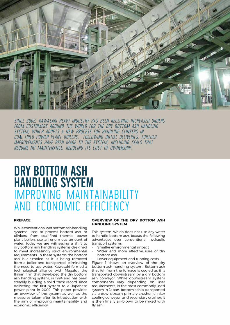
While conventional wet bottom ash handling systems used to process bottom ash, or clinkers, from coal-fired thermal power plant boilers use an enormous amount of water, today we are witnessing a shift to dry bottom ash handling systems designed to meet increasingly strict environmental requirements. in these systems the bottom ash is air-cooled as it is being removed from a boiler and transported, eliminating the need to use water, kawasaki formed a technological alliance with magaldi, the italian firm that developed the dry bottom ash handling system, in 1994 and has been steadily building a solid track record since delivering the first system to a Japanese power plant in 2002. This paper provides an overview of the system as well as the measures taken after its introduction with the aim of improving maintainability and economic efficiency.
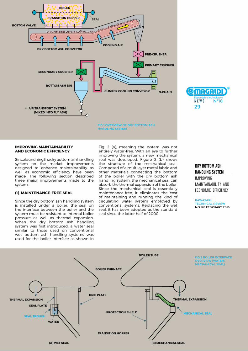
overvieW oF The dry BoTToM ash handlinG sysTeM
This system, which does not use any water to handle bottom ash, boasts the following advantages over conventional hydraulic transport systems:- smaller environmental impact- Wider and more effective uses of dry
bottom ash- lower equipment and running costsfigure 1 shows an overview of the dry bottom ash handling system. Bottom ash that fell from the furnace is cooled as it is transported downstream by a dry bottom ash conveyor. While downstream system components vary depending on user requirements, in the most commonly used system in Japan, bottom ash is transported via a downstream primary crusher, clinker cooling conveyor, and secondary crusher. it is then finally air-blown to be mixed with fly ash.
since 2002, KawasaKi heavy inDustry has been receiving increaseD orDers froM custoMers arounD the worlD for the Dry bottoM ash hanDling systeM, which aDopts a new process for hanDling clinKers in coal-fireD power plant boilers. following initial Deliveries, further iMproveMents have been MaDe to the systeM, incluDing seals that require no Maintenance, reDucing its cost of ownership.
N E W S N°1829
dry bottoM aSh haNdliNg SyStEM improving mainTainabiliTy and economic efficiency
kawasaki teChNiCal review No.176 february 2016
iMprovinG MainTainaBiliTy and econoMic eFFiciency
since launching the dry bottom ash handling system on the market, improvements designed to enhance maintainability as well as economic efficiency have been made. The following section described three major improvements made to the system.
(1) MainTenance-Free seal
since the dry bottom ash handling system is installed under a boiler, the seal on the interface between the boiler and the system must be resistant to internal boiler pressure as well as thermal expansion. When the dry bottom ash handling system was first introduced, a water seal similar to those used on conventional wet bottom ash handling systems was used for the boiler interface as shown in
fig. 2 (a), meaning the system was not entirely water-free. With an eye to further improving the system, a new mechanical seal was developed. figure 2 (b) shows the structure of the mechanical seal. composed of a multilayer metal fabric and other materials connecting the bottom of the boiler with the dry bottom ash handling system, the mechanical seal can absorb the thermal expansion of the boiler. since the mechanical seal is essentially maintenance-free, it eliminates the cost of maintaining and running the kind of circulating water system employed by conventional systems. replacing the wet seal, it has been adopted as the standard seal since the latter half of 2000.
THERMAL EXPANSION
SEAL TROUGH
WATER
SEAL PLATE
DRIP PLATE
BOILER FURNACE
TRANSITION HOPPER
BOILER TUBE
THERMAL EXPANSION
MECHANICAL SEALPROTECTION SHIELD
(A) WET SEAL (B) MECHANICAL SEAL
fig.2 boiler iNterfaCe overvIew (wATer/MeChaNiCal seal)
BOILER
TRANSITION HOPPER SEAL
BOTTOM VALVE
DRY BOTTOM ASH CONVEYORCOOLING AIR
PRE-CRUSHER
PRIMARY CRUSHER
O-CHAINCLINKER COOLING CONVEYOR
SECONDARY CRUSHER
BOTTOM ASH BIN
← AIR TRANSPORT SYSTEM (MIXED INTO FLY ASH)
fig.1 overview of dry bottoM ash haNdliNg systeM
FLOW OF FALLING ASH (FINE PARTICLES)
NORMAL CLINKER FLOW
CLINKER COOLING CONVEYOR ASH COLLECTOR (O-CHAIN)
3. THE O-CHAIN FEEDS THEASH BACK ONTO THE CONVEYOR
2. THE ASH IS PLACED ON THE O-CHAIN
CLINKER COOLING CONVEYOR
1. THE FLAPS ATTACHED TO THE BELT COLLECT FALLING ASH AS THE CONVEYOR MAKES ITS RETURN
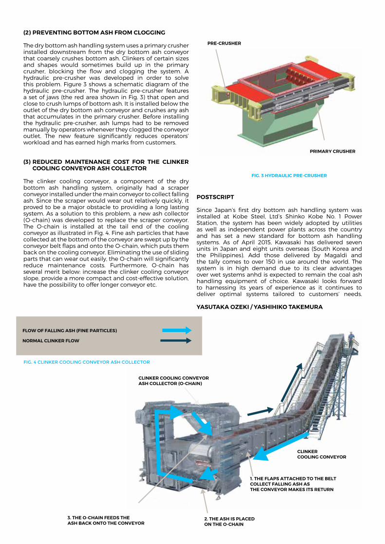
(2) prevenTinG BoTToM ash FroM cloGGinG
The dry bottom ash handling system uses a primary crusher installed downstream from the dry bottom ash conveyor that coarsely crushes bottom ash. clinkers of certain sizes and shapes would sometimes build up in the primary crusher, blocking the flow and clogging the system. a hydraulic pre-crusher was developed in order to solve this problem. figure 3 shows a schematic diagram of the hydraulic pre-crusher. The hydraulic pre-crusher features a set of jaws (the red area shown in fig. 3) that open and close to crush lumps of bottom ash. it is installed below the outlet of the dry bottom ash conveyor and crushes any ash that accumulates in the primary crusher. Before installing the hydraulic pre-crusher, ash lumps had to be removed manually by operators whenever they clogged the conveyor outlet. The new feature significantly reduces operators’ workload and has earned high marks from customers.
(3) reduced MainTenance cosT For The clinker coolinG conveyor ash collecTor
The clinker cooling conveyor, a component of the dry bottom ash handling system, originally had a scraper conveyor installed under the main conveyor to collect falling ash. since the scraper would wear out relatively quickly, it proved to be a major obstacle to providing a long lasting system. as a solution to this problem, a new ash collector (o-chain) was developed to replace the scraper conveyor. The o-chain is installed at the tail end of the cooling conveyor as illustrated in fig. 4. fine ash particles that have collected at the bottom of the conveyor are swept up by the conveyor belt flaps and onto the o-chain, which puts them back on the cooling conveyor. eliminating the use of sliding parts that can wear out easily, the o-chain will significantly reduce maintenance costs. furthermore, o-chain has several merit below: increase the clinker cooling conveyor slope, provide a more compact and cost-effective solution, have the possibility to offer longer conveyor etc.
posTscripT
since Japan’s first dry bottom ash handling system was installed at kobe steel, ltd’s shinko kobe no. 1 Power station, the system has been widely adopted by utilities as well as independent power plants across the country and has set a new standard for bottom ash handling systems. as of april 2015, kawasaki has delivered seven units in Japan and eight units overseas (south korea and the Philippines). add those delivered by magaldi and the tally comes to over 150 in use around the world. The system is in high demand due to its clear advantages over wet systems anhd is expected to remain the coal ash handling equipment of choice. kawasaki looks forward to harnessing its years of experience as it continues to deliver optimal systems tailored to customers’ needs.
yasuTaka oZeki / yashihiko TakeMura
PRE-CRUSHER
PRIMARY CRUSHER
FIG. 3 HYDRAULIC PRE-CRUSHER
fig. 4 CliNker CooliNg CoNveyor ash ColleCtor
N E W S N°1831
Magaldi caStiNg cooliNg tEchNologiES
inTroducTion
secondary cooling plays an important role in the continuous casting production. in recent decades, a dramatic growth of this metal processing technology has been realized in both steel and aluminium industries, owing to a substantial increase in yield, energy savings and productivity.
however, the technological advancement has taken different routes for these two metal industries. over the years, the casting procedures for steel and aluminium alloy products have developed distinctive features in terms of casting practices, machinery, process and quality control methodologies. The productivity of both processes is controlled by the casting speed, so higher speeds are always required. however, the casting speed cannot be increased arbitrarily for several reasons.
The modern foundry has the necessity to decrease the required cooling time and the casting cooler represents the solution to gain such target. furthermore, the casting cooler is a must when the shot blasting machine is in line.
To perform casting cooling there are different ways such as rotating drums, vibrating coolers, carousels or also natural cooling in racks. The option to perform cooling by water is even possible but often less suggested.
The magaldi casting cooler (mcc®) overcomes the limitation of water cooling and conventional methods that may cause production losses due to different reasons. The mcc® cools the castings dependably and optimizes the cooling efficiency.
The automotive industry is the fastest-growing market segment for aluminum suppliers. driving the growth is aluminum’s ability to reduce weight, which helps decreasing fuel consumption and improves all-around performance in the vehicle.
The first mcc® reference in iron plants drove the aluminum foundries to ask magaldi for a casting cooling. The last Gifa was the opportunity to meet nemak, the world largest aluminum manufacturer, that encouraged magaldi to study a tailored mcc solution for their plants: for magaldi a new interesting cooling experience!
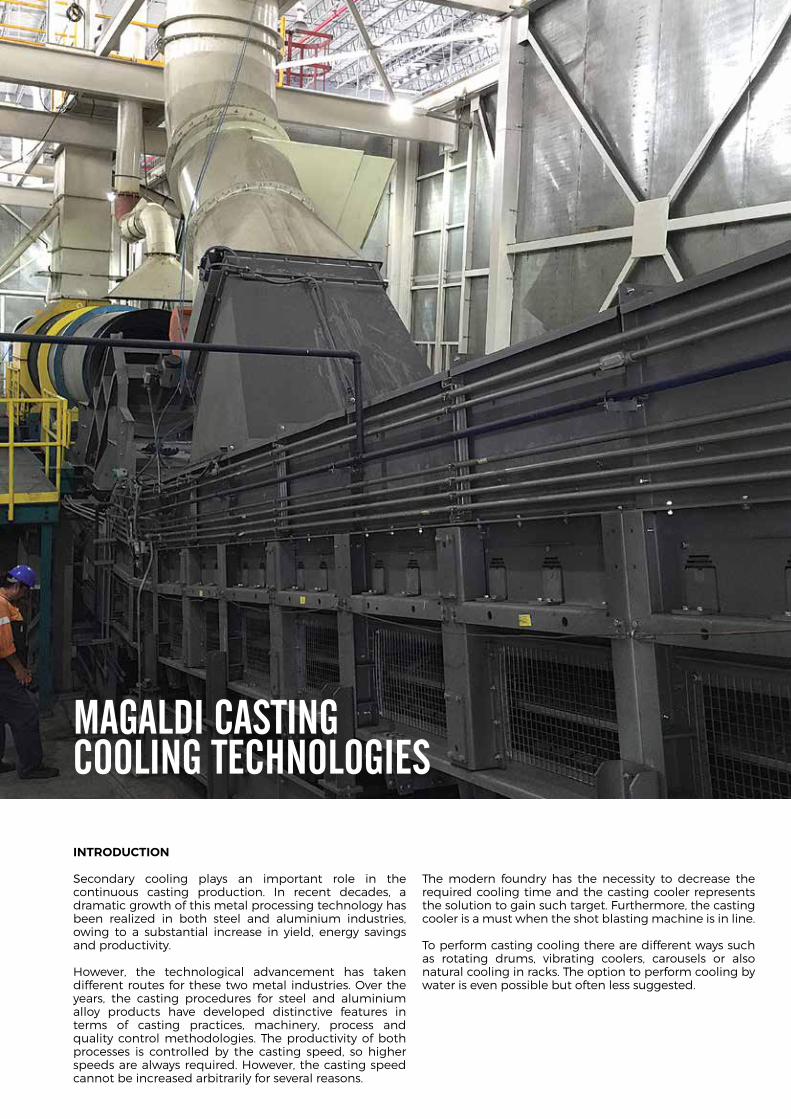
COVER
SKIRTBOARDS WITH SEALING BLOCKS
SUPERBELTWITH AIR SLOTS
AIR INLET AIR INLET
N E W S N°1833
Magaldi caStiNg cooliNg tEchNologiES producToverview
aNtoNello Marrazzoarea MaNager
gaetaNo CoraggioProCess eNgiNeer
Product overview
MaGaldi casTinG cooler - Mcc®
The magaldi casting cooler - mcc® - is an automated system for the transportation and cooling of castings downstream the molding lines and it can be also a valuable workstation for de-gating operation, avoiding the need for a further conveyor.
specifically designed to ensure both a dependable handling / cooling of castings and the maximum productivity, the mcc® is able to work in the most difficult conditions as high temperatures, heavy loads, abrasive or sharp castings.The magaldi casting cooler is equipped with a cooling tunnel, held under negative pressure, in which a stream of cooling air flows at controlled speed to avoid thermal shocks to the castings. ambient air is forced to enter the extremities of the cooling tunnel and it is then sucked from the center of the tunnel itself.
The cooling tunnel is provided with a set of optical pyrometers for casting temperature detection at different points along the transportation (inlet, middle and outlet of the tunnel). downstream the cooling tunnel the uncovered remaining part of the mcc® allows operators to comfortably de-gate the cooled castings and to sort the sprues by sliding them down out, without noise and vibration, thanks to the conveyor’s low speed and available large flat work surface (if required). The cooled and de-gated castings are then conveyed to the shot blasting machine.The mcc® in conjunction with the magaldi integrated supervision system (miss®) manages and controls the cooling air flow depending on inlet casting temperature and varying the belt speed according to the scheduled id type of casting to be cooled.
The miss® interfaces with optical pyrometers placed along the cooling tunnel, receives id castings data coming from the molding line along with all the status signals of the magaldi installation in order to manage and control cooling and conveying processes according to the customized logical design.
Proprietary calculations methods allow to forecast and guarantee mcc® system cooling performances.
super MaGaldi casTinG cooler - Mcc®
one of the most frequent customer requests is about compacting overall dimensions of cooling solution both in case of green field and retrofit projects, being layout changes quite a challenge in the latter case. after thermal simulation and relevant research, a new mcc® configuration has been developed (super mcc®) in order to obtain the proven mcc® benefit and performance in a shorter space.nowadays the super mcc® represents the best solution to cool typical castings like brake discs, flywheels, calipers and all those castings able to fill superbelt® in a “bulk material” way.like the mcc® solution, the super mcc® system is equipped with an air forced cooling tunnel held under negative pressure by a venting system to ensure current air flow cooling conditions.
in addition, the steel belt conveyor of the super mcc® is equipped with slots suitably sized to perform additional cooling of castings. Thanks to negative pressure in the tunnel, ambient air is driven through the conveyor belt slots and through the “bulk” of castings on it obtaining a higher efficient “cross flow” thermal exchange between air and castings.The super mcc® system combines two heat exchange mechanisms, counter-current flow and cross flow resulting in air cooling performances thus allowing to optimize both cooling dimensions and power requirement.When casting unloading point is in elevated position super mcc® conveyor can be equipped with steel bars to avoid castings slipping or rolling back during conveying in the inclined part of the conveyor.
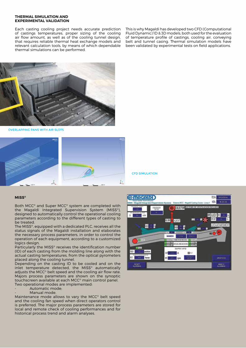
TherMal siMulaTion and experiMenTal validaTion
each casting cooling project needs accurate prediction of castings temperatures, proper sizing of the cooling air flow amount, as well as of the cooling tunnel design, that requires reliable thermal heat exchange models and relevant calculation tools, by means of which dependable thermal simulations can be performed.
This is why magaldi has developed two cfd (computational fluid dynamic) 1d & 3d models, both used for the evaluation of temperature profile of castings, cooling air, conveying belt and tunnel casing. Thermal simulation models have been validated by experimental tests on field applications.
Miss®
Both mcc® and super mcc® system are completed with the magaldi integrated supervision system (miss®), designed to automatically control the operational cooling parameters according to the different types of casting to be treated.The miss®, equipped with a dedicated Plc, receives all the status signals of the magaldi installation and elaborates the necessary process parameters, in order to control the operation of each equipment, according to a customized logics design. Particularly the miss® receives the identification number (id) of each casting from the molding line along with the actual casting temperatures, from the optical pyrometers placed along the cooling tunnel. depending on the casting id to be cooled and on the inlet temperature detected, the miss® automatically adjusts the mcc® belt speed and the cooling air flow rate. majors process parameters are shown on the synoptic touchscreen available at each mcc® main control panel.Two operational modes are implemented: - automatic mode;- manual mode.maintenance mode allows to vary the mcc® belt speed and the cooling fan speed when direct operators control is preferred. The major process parameters are stored for local and remote check of cooling performances and for historical process trend and alarm analyses.
Cfd siMulatioN
overlaPPiNg PaNs with air slots
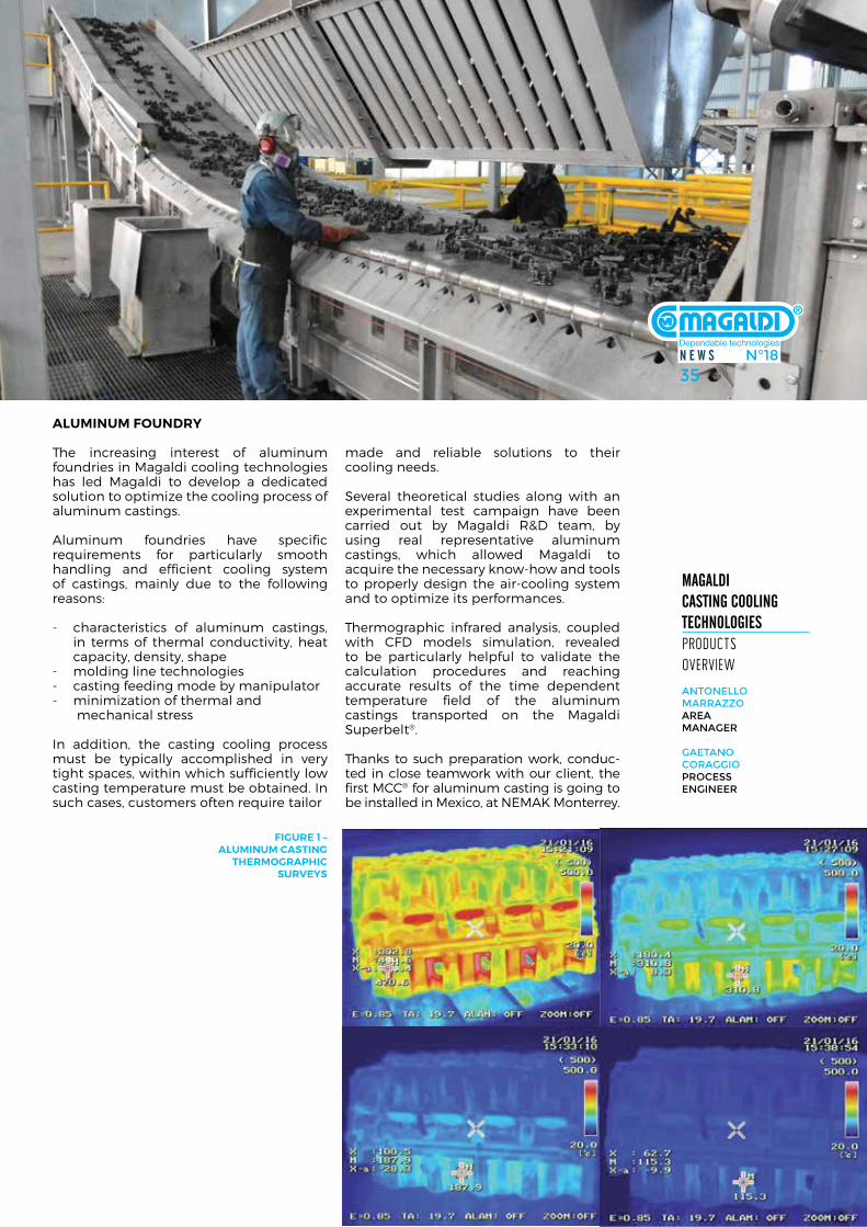
N E W S N°1835
Magaldi caStiNg cooliNg tEchNologiES producTs overview
aNtoNello Marrazzoarea MaNager
gaetaNo CoraggioProCess eNgiNeer
aluMinuM Foundry
The increasing interest of aluminum foundries in magaldi cooling technologies has led magaldi to develop a dedicated solution to optimize the cooling process of aluminum castings.
aluminum foundries have specific requirements for particularly smooth handling and efficient cooling system of castings, mainly due to the following reasons:
- characteristics of aluminum castings, in terms of thermal conductivity, heat capacity, density, shape
- molding line technologies - casting feeding mode by manipulator - minimization of thermal and mechanical stress
in addition, the casting cooling process must be typically accomplished in very tight spaces, within which sufficiently low casting temperature must be obtained. in such cases, customers often require tailor
made and reliable solutions to their cooling needs.
several theoretical studies along with an experimental test campaign have been carried out by magaldi r&d team, by using real representative aluminum castings, which allowed magaldi to acquire the necessary know-how and tools to properly design the air-cooling system and to optimize its performances.
Thermographic infrared analysis, coupled with cfd models simulation, revealed to be particularly helpful to validate the calculation procedures and reaching accurate results of the time dependent temperature field of the aluminum castings transported on the magaldi superbelt®.
Thanks to such preparation work, conduc- ted in close teamwork with our client, the first mcc® for aluminum casting is going to be installed in mexico, at nemak monterrey.
FiGure 1 – aluMinuM casTinG
TherMoGraphic surveys
N E W S N°1835
Cfd siMulatioN
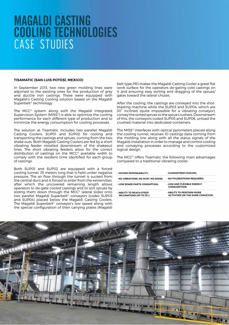
Magaldi caStiNg cooliNg tEchNologiES case sTudies
TisaMaTic (san luis poTosì, Mexico)
in september 2013, two new green molding lines were adjoined to the existing ones for the production of grey and ductile iron castings. These were equipped with magaldi’s casting cooling solution based on the magaldi superbelt® technology.
The mcc® system along with the magaldi integrated supervision system (miss®) is able to optimize the cooling performance for each different type of production and to minimize the energy consumption for cooling processes.
The solution at Tisamatic includes two parallel magaldi casting coolers, suP01 and suP02 for cooling and transporting the castings and sprues, coming from the two shake outs. Both magaldi casting coolers are fed by a short vibrating feeder installed downstream of the shakeout lines. The short vibrating feeders allow for the correct distribution of castings on the mcc® available width to comply with the resident time identified for each group of castings.
Both suP01 and suP02 are equipped with a forced cooling tunnel, 35 meters long that is held under negative pressure. The air flow through the tunnel is sucked from the central duct and is forced to enter from the extremities, after which the uncovered remaining length allows operators to de-gate cooled castings and to sort sprues by sliding them down through the mcc® lateral slides onto two parallel magaldi superbelt® conveyors (codes suP03 and suP04) placed below the magaldi casting coolers. The magaldi superbelt® conveyor’s low speed along with the special configuration of their carrying plates (magaldi
belt type Pr) makes the magaldi casting cooler a great flat work surface for the operators de-gating cold castings on it and ensuring easy sorting and dragging of the sprues/gates toward the lateral chutes.
after the cooling, the castings are conveyed into the shot-blasting machine while the suP03 and suP04, which are 30° inclined (quite impossible for a vibrating conveyor), convey the sorted sprues to the sprue crushers. downstream of this, the conveyors coded suP05 and suP06, unload the crushed material into dedicated containers.
The miss® interfaces with optical pyrometers placed along the cooling tunnel, receives id castings data coming from the molding line along with all the status signals of the magaldi installation in order to manage and control cooling and conveying processes according to the customized logical design.
The mcc® offers Tisamatic the following main advantages compared to a traditional vibrating cooler:
- GuaranTeed coolinG;
- no FoundaTions required;
- loW and FlexiBle enerGy consuMpTion;
- aBiliTy To perForM More acTiviTies on The saMe conveyor.
- hiGher dependaBiliTy;
- no viBraTions, no dusT, no noise;
- loW spare parTs consupTion;
- aBiliTy To reach sTeep inclinaTions (up To 35°);
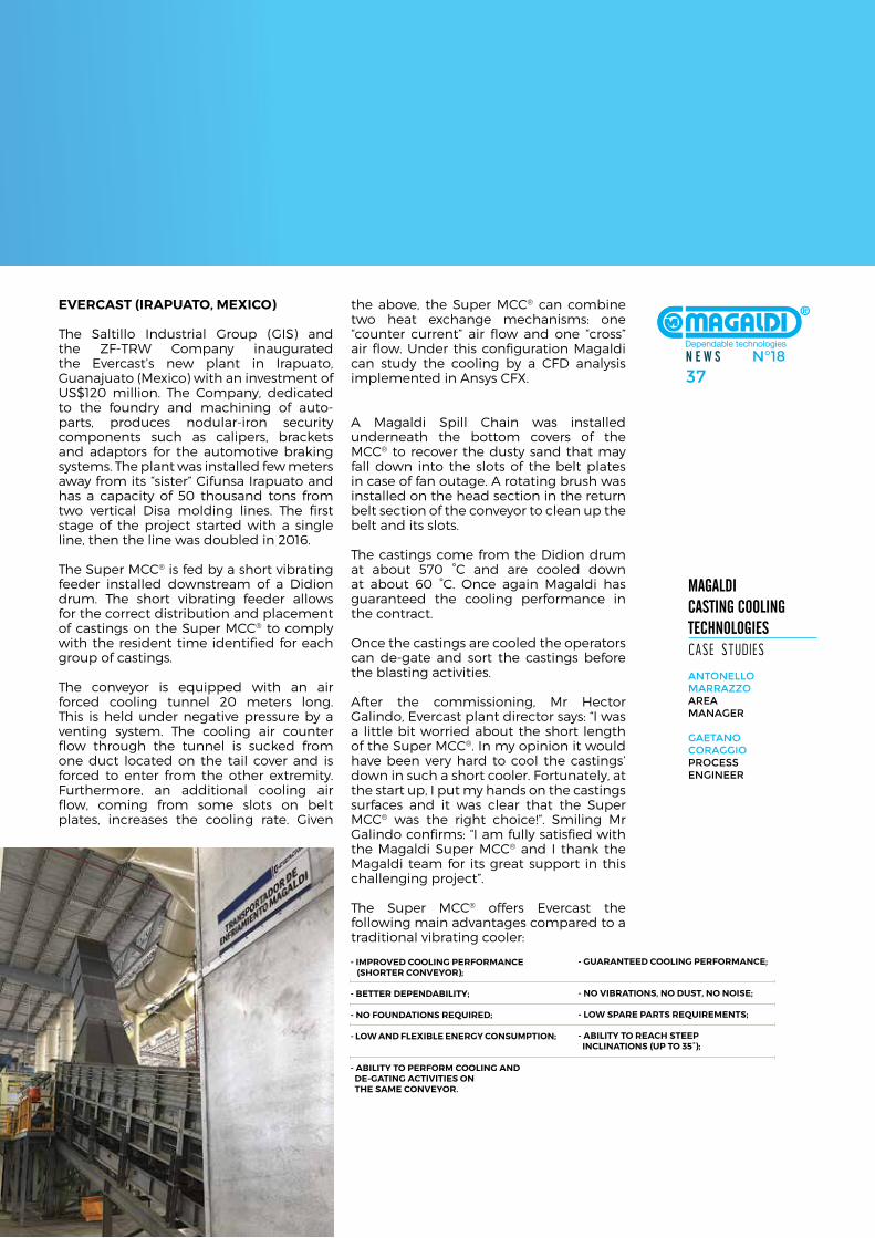
N E W S N°1837
Magaldi caStiNg cooliNg tEchNologiES case sTudies
aNtoNello Marrazzoarea MaNager
gaetaNo CoraggioProCess eNgiNeer
evercasT (irapuaTo, Mexico)
The saltillo industrial Group (Gis) and the Zf-TrW company inaugurated the evercast’s new plant in irapuato, Guanajuato (mexico) with an investment of us$120 million. The company, dedicated to the foundry and machining of auto-parts, produces nodular-iron security components such as calipers, brackets and adaptors for the automotive braking systems. The plant was installed few meters away from its “sister” cifunsa irapuato and has a capacity of 50 thousand tons from two vertical disa molding lines. The first stage of the project started with a single line, then the line was doubled in 2016.
The super mcc® is fed by a short vibrating feeder installed downstream of a didion drum. The short vibrating feeder allows for the correct distribution and placement of castings on the super mcc® to comply with the resident time identified for each group of castings.
The conveyor is equipped with an air forced cooling tunnel 20 meters long. This is held under negative pressure by a venting system. The cooling air counter flow through the tunnel is sucked from one duct located on the tail cover and is forced to enter from the other extremity. furthermore, an additional cooling air flow, coming from some slots on belt plates, increases the cooling rate. Given
the above, the super mcc® can combine two heat exchange mechanisms: one “counter current” air flow and one “cross” air flow. under this configuration magaldi can study the cooling by a cfd analysis implemented in ansys cfX.
a magaldi spill chain was installed underneath the bottom covers of the mcc® to recover the dusty sand that may fall down into the slots of the belt plates in case of fan outage. a rotating brush was installed on the head section in the return belt section of the conveyor to clean up the belt and its slots.
The castings come from the didion drum at about 570 °c and are cooled down at about 60 °c. once again magaldi has guaranteed the cooling performance in the contract.
once the castings are cooled the operators can de-gate and sort the castings before the blasting activities.
after the commissioning, mr hector Galindo, evercast plant director says: “i was a little bit worried about the short length of the super mcc®. in my opinion it would have been very hard to cool the castings’ down in such a short cooler. fortunately, at the start up, i put my hands on the castings surfaces and it was clear that the super mcc® was the right choice!”. smiling mr Galindo confirms: “i am fully satisfied with the magaldi super mcc® and i thank the magaldi team for its great support in this challenging project”.
The super mcc® offers evercast the following main advantages compared to a traditional vibrating cooler:
- GuaranTeed coolinG perForMance;
- no viBraTions, no dusT, no noise;
- loW spare parTs requireMenTs;
- aBiliTy To reach sTeep inclinaTions (up To 35°);
- iMproved coolinG perForMance (shorTer conveyor);
- BeTTer dependaBiliTy;
- no FoundaTions required;
- loW and FlexiBle enerGy consuMpTion;
- aBiliTy To perForM coolinG and de-GaTinG acTiviTies on The saMe conveyor.
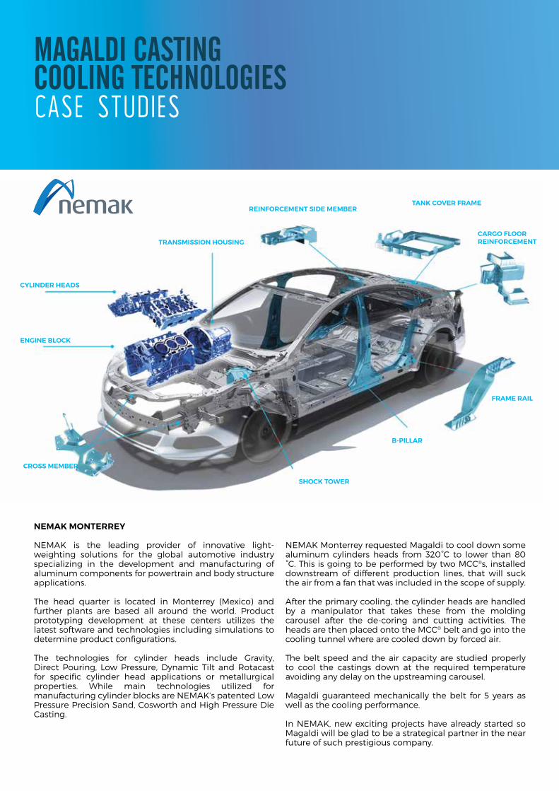
neMak MonTerrey
nemak is the leading provider of innovative light-weighting solutions for the global automotive industry specializing in the development and manufacturing of aluminum components for powertrain and body structure applications.
The head quarter is located in monterrey (mexico) and further plants are based all around the world. Product prototyping development at these centers utilizes the latest software and technologies including simulations to determine product configurations. The technologies for cylinder heads include Gravity, direct Pouring, low Pressure, dynamic Tilt and rotacast for specific cylinder head applications or metallurgical properties. While main technologies utilized for manufacturing cylinder blocks are nemak’s patented low Pressure Precision sand, cosworth and high Pressure die casting.
nemak monterrey requested magaldi to cool down some aluminum cylinders heads from 320°c to lower than 80 °c. This is going to be performed by two mcc®s, installed downstream of different production lines, that will suck the air from a fan that was included in the scope of supply.
after the primary cooling, the cylinder heads are handled by a manipulator that takes these from the molding carousel after the de-coring and cutting activities. The heads are then placed onto the mcc® belt and go into the cooling tunnel where are cooled down by forced air.
The belt speed and the air capacity are studied properly to cool the castings down at the required temperature avoiding any delay on the upstreaming carousel.
magaldi guaranteed mechanically the belt for 5 years as well as the cooling performance.
in nemak, new exciting projects have already started so magaldi will be glad to be a strategical partner in the near future of such prestigious company.
CYLINDER HEADS
ENGINE BLOCK
TRANSMISSION HOUSING
REINFORCEMENT SIDE MEMBERTANK COVER FRAME
CARGO FLOORREINFORCEMENT
FRAME RAIL
B-PILLAR
SHOCK TOWER
CROSS MEMBER
Magaldi caStiNg cooliNg tEchNologiES case sTudies
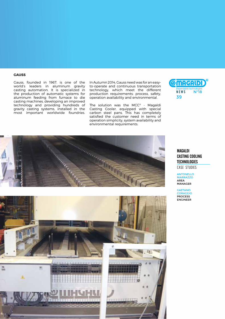
N E W S N°1839
Magaldi caStiNg cooliNg tEchNologiES case sTudies
aNtoNello Marrazzoarea MaNager
gaetaNo CoraggioProCess eNgiNeer
Gauss
Gauss, founded in 1967, is one of the world’s leaders in aluminum gravity casting automation. it is specialized in the production of automatic systems for aluminum feeding from furnace to die casting machines, developing an improved technology and providing hundreds of gravity casting systems, installed in the most important worldwide foundries.
in autumn 2014, Gauss need was for an easy-to-operate and continuous transportation technology, which meet the different production requirements: process, safety, operation availability and environmental.
The solution was the mcc® - magaldi casting cooler, equipped with special carbon steel pans. This has completely satisfied the customer need in terms of operation simplicity, system availability and environmental requirements.
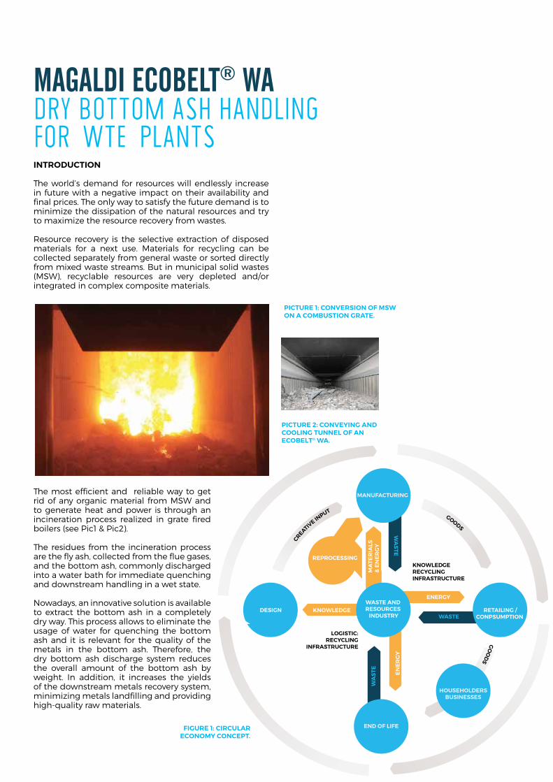
WA
STE EN
ER
GY
MANUFACTURING
END OF LIFE
WASTE AND RESOURCES
INDUSTRYDESIGN RETAILING /
CONPSUMPTION WASTE
WA
STE
KNOWLEDGE
ENERGY
MA
TER
IALS
&
EN
ER
GY
LOGISTIC:RECYCLING
INFRASTRUCTURE
KNOWLEDGERECYCLINGINFRASTRUCTURE
REPROCESSING
HOUSEHOLDERSBUSINESSES
Magaldi EcobElt® Wa dry boTTom ash handling for wTe planTs inTroducTion
The world’s demand for resources will endlessly increase in future with a negative impact on their availability and final prices. The only way to satisfy the future demand is to minimize the dissipation of the natural resources and try to maximize the resource recovery from wastes.
resource recovery is the selective extraction of disposed materials for a next use. materials for recycling can be collected separately from general waste or sorted directly from mixed waste streams. But in municipal solid wastes (msW), recyclable resources are very depleted and/or integrated in complex composite materials.
The most efficient and reliable way to get rid of any organic material from msW and to generate heat and power is through an incineration process realized in grate fired boilers (see Pic1 & Pic2).
The residues from the incineration process are the fly ash, collected from the flue gases, and the bottom ash, commonly discharged into a water bath for immediate quenching and downstream handling in a wet state.
nowadays, an innovative solution is available to extract the bottom ash in a completely dry way. This process allows to eliminate the usage of water for quenching the bottom ash and it is relevant for the quality of the metals in the bottom ash. Therefore, the dry bottom ash discharge system reduces the overall amount of the bottom ash by weight. in addition, it increases the yields of the downstream metals recovery system, minimizing metals landfilling and providing high-quality raw materials.
picTure 1: conversion oF MsW on a coMBusTion GraTe.
picTure 2: conveyinG and coolinG Tunnel oF an ecoBelT® Wa.
FiGure 1: circular econoMy concepT.
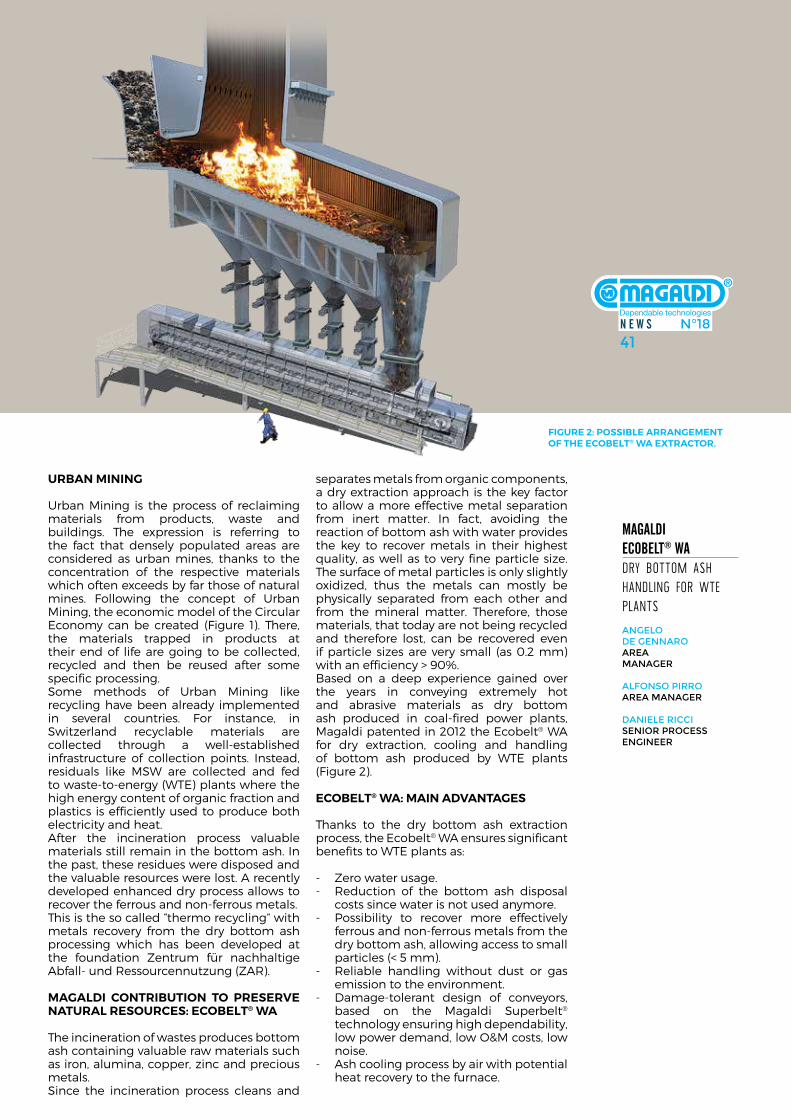
N E W S N°1841
WA
STE EN
ER
GY
MANUFACTURING
END OF LIFE
WASTE AND RESOURCES
INDUSTRYDESIGN RETAILING /
CONPSUMPTION WASTE
WA
STE
KNOWLEDGE
ENERGY
MA
TER
IALS
&
EN
ER
GY
LOGISTIC:RECYCLING
INFRASTRUCTURE
KNOWLEDGERECYCLINGINFRASTRUCTURE
REPROCESSING
HOUSEHOLDERSBUSINESSES
Magaldi EcobElt® Wa dry boTTom ash handling for wTe planTs
aNgelo de geNNaro area MaNager
alfoNso Pirroarea MaNager
daNiele riCCiseNior ProCess eNgiNeer
urBan MininG
urban mining is the process of reclaiming materials from products, waste and buildings. The expression is referring to the fact that densely populated areas are considered as urban mines, thanks to the concentration of the respective materials which often exceeds by far those of natural mines. following the concept of urban mining, the economic model of the circular economy can be created (figure 1). There, the materials trapped in products at their end of life are going to be collected, recycled and then be reused after some specific processing.some methods of urban mining like recycling have been already implemented in several countries. for instance, in switzerland recyclable materials are collected through a well-established infrastructure of collection points. instead, residuals like msW are collected and fed to waste-to-energy (WTe) plants where the high energy content of organic fraction and plastics is efficiently used to produce both electricity and heat. after the incineration process valuable materials still remain in the bottom ash. in the past, these residues were disposed and the valuable resources were lost. a recently developed enhanced dry process allows to recover the ferrous and non-ferrous metals.This is the so called “thermo recycling” with metals recovery from the dry bottom ash processing which has been developed at the foundation Zentrum für nachhaltige abfall- und ressourcennutzung (Zar).
MaGaldi conTriBuTion To preserve naTural resources: ecoBelT® Wa
The incineration of wastes produces bottom ash containing valuable raw materials such as iron, alumina, copper, zinc and precious metals.since the incineration process cleans and
separates metals from organic components, a dry extraction approach is the key factor to allow a more effective metal separation from inert matter. in fact, avoiding the reaction of bottom ash with water provides the key to recover metals in their highest quality, as well as to very fine particle size. The surface of metal particles is only slightly oxidized, thus the metals can mostly be physically separated from each other and from the mineral matter. Therefore, those materials, that today are not being recycled and therefore lost, can be recovered even if particle sizes are very small (as 0.2 mm) with an efficiency > 90%.Based on a deep experience gained over the years in conveying extremely hot and abrasive materials as dry bottom ash produced in coal-fired power plants, magaldi patented in 2012 the ecobelt® Wa for dry extraction, cooling and handling of bottom ash produced by WTe plants (figure 2).
ecoBelT® Wa: Main advanTaGes
Thanks to the dry bottom ash extraction process, the ecobelt® Wa ensures significant benefits to WTe plants as:
- Zero water usage.- reduction of the bottom ash disposal
costs since water is not used anymore.- Possibility to recover more effectively
ferrous and non-ferrous metals from the dry bottom ash, allowing access to small particles (< 5 mm).
- reliable handling without dust or gas emission to the environment.
- damage-tolerant design of conveyors, based on the magaldi superbelt® technology ensuring high dependability, low power demand, low o&m costs, low noise.
- ash cooling process by air with potential heat recovery to the furnace.
FiGure 2: possiBle arranGeMenT oF The ecoBelT® Wa exTracTor.
N E W S N°1841
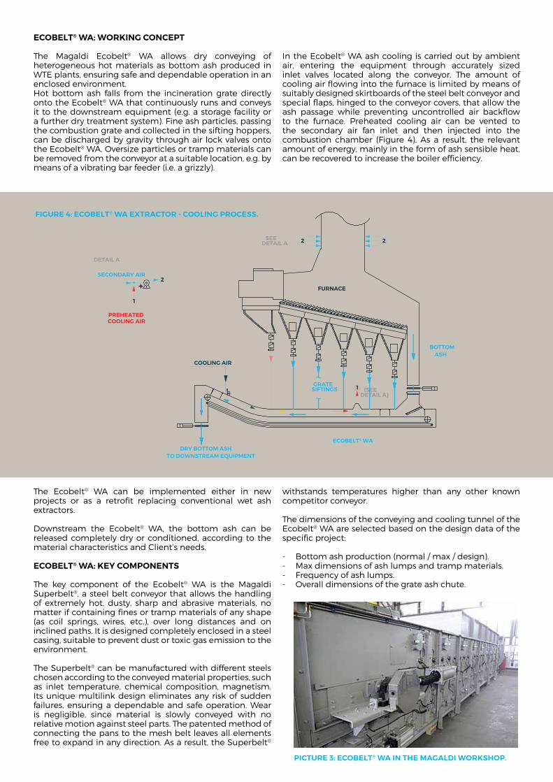
FURNACE
BOTTOMASH
COOLING AIR
ECOBELT® WADRY BOTTOM ASH
TO DOWNSTREAM EQUIPMENT
GRATESIFTINGS 1 (SEE
DETAIL A)
SECONDARY AIR
1
2
DETAIL A
PREHEATEDCOOLING AIR
2 2SEEDETAIL A
ecoBelT® Wa: WorkinG concepT
The magaldi ecobelt® Wa allows dry conveying of heterogeneous hot materials as bottom ash produced in WTe plants, ensuring safe and dependable operation in an enclosed environment.hot bottom ash falls from the incineration grate directly onto the ecobelt® Wa that continuously runs and conveys it to the downstream equipment (e.g. a storage facility or a further dry treatment system). fine ash particles, passing the combustion grate and collected in the sifting hoppers, can be discharged by gravity through air lock valves onto the ecobelt® Wa. oversize particles or tramp materials can be removed from the conveyor at a suitable location, e.g. by means of a vibrating bar feeder (i.e. a grizzly).
in the ecobelt® Wa ash cooling is carried out by ambient air, entering the equipment through accurately sized inlet valves located along the conveyor. The amount of cooling air flowing into the furnace is limited by means of suitably designed skirtboards of the steel belt conveyor and special flaps, hinged to the conveyor covers, that allow the ash passage while preventing uncontrolled air backflow to the furnace. Preheated cooling air can be vented to the secondary air fan inlet and then injected into the combustion chamber (figure 4). as a result, the relevant amount of energy, mainly in the form of ash sensible heat, can be recovered to increase the boiler efficiency.
The ecobelt® Wa can be implemented either in new projects or as a retrofit replacing conventional wet ash extractors.
downstream the ecobelt® Wa, the bottom ash can be released completely dry or conditioned, according to the material characteristics and client’s needs.
ecoBelT® Wa: key coMponenTs
The key component of the ecobelt® Wa is the magaldi superbelt®, a steel belt conveyor that allows the handling of extremely hot, dusty, sharp and abrasive materials, no matter if containing fines or tramp materials of any shape (as coil springs, wires, etc.), over long distances and on inclined paths. it is designed completely enclosed in a steel casing, suitable to prevent dust or toxic gas emission to the environment.
The superbelt® can be manufactured with different steels chosen according to the conveyed material properties, such as inlet temperature, chemical composition, magnetism. its unique multilink design eliminates any risk of sudden failures, ensuring a dependable and safe operation. Wear is negligible, since material is slowly conveyed with no relative motion against steel parts. The patented method of connecting the pans to the mesh belt leaves all elements free to expand in any direction. as a result, the superbelt®
withstands temperatures higher than any other known competitor conveyor.
The dimensions of the conveying and cooling tunnel of the ecobelt® Wa are selected based on the design data of the specific project:
- Bottom ash production (normal / max / design).- max dimensions of ash lumps and tramp materials.- frequency of ash lumps.- overall dimensions of the grate ash chute.
picTure 3: ecoBelT® Wa in The MaGaldi Workshop.
FiGure 4: ecoBelT® Wa exTracTor - coolinG process.
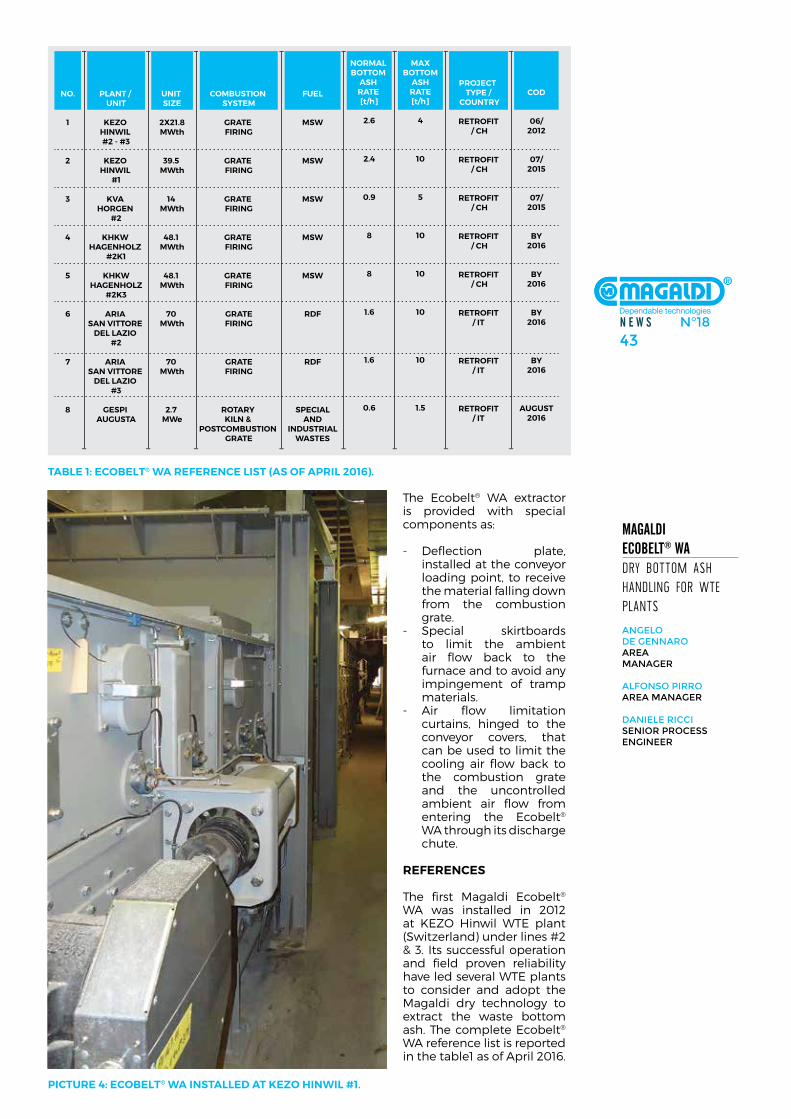
N E W S N°1843
Magaldi EcobElt® Wa dry boTTom ash handling for wTe planTs
aNgelo de geNNaro area MaNager
alfoNso Pirroarea MaNager
daNiele riCCiseNior ProCess eNgiNeer
The ecobelt® Wa extractor is provided with special components as:
- deflection plate, installed at the conveyor loading point, to receive the material falling down from the combustion grate.
- special skirtboards to limit the ambient air flow back to the furnace and to avoid any impingement of tramp materials.
- air flow limitation curtains, hinged to the conveyor covers, that can be used to limit the cooling air flow back to the combustion grate and the uncontrolled ambient air flow from entering the ecobelt® Wa through its discharge chute.
reFerences
The first magaldi ecobelt® Wa was installed in 2012 at keZo hinwil WTe plant (switzerland) under lines #2 & 3. its successful operation and field proven reliability have led several WTe plants to consider and adopt the magaldi dry technology to extract the waste bottom ash. The complete ecobelt® Wa reference list is reported in the table1 as of april 2016.
picTure 4: ecoBelT® Wa insTalled aT keZo hinWil #1.
TaBle 1: ecoBelT® Wa reFerence lisT (as oF april 2016).
NO.
1
2
3
4
5
6
7
8
PLANT / UNIT
KEZO HINWIL #2 - #3
KEZO HINWIL
#1
KVA HORGEN
#2
KHKW HAGENHOLZ
#2K1
KHKW HAGENHOLZ
#2K3
ARIA SAN VITTORE
DEL LAZIO #2
ARIA SAN VITTORE
DEL LAZIO #3
GESPI AUGUSTA
UNIT SIZE
2X21.8MWth
39.5 MWth
14 MWth
48.1 MWth
48.1 MWth
70 MWth
70 MWth
2.7 MWe
COMBUSTION SYSTEM
GRATE FIRING
GRATE FIRING
GRATE FIRING
GRATE FIRING
GRATE FIRING
GRATEFIRING
GRATEFIRING
ROTARY KILN &
POSTCOMBUSTION GRATE
FUEL
MSW
MSW
MSW
MSW
MSW
RDF
RDF
SPECIALAND
INDUSTRIALWASTES
PROJECT TYPE /
COUNTRY
RETROFIT / CH
RETROFIT / CH
RETROFIT / CH
RETROFIT / CH
RETROFIT / CH
RETROFIT/ IT
RETROFIT/ IT
RETROFIT/ IT
COD
06/2012
07/2015
07/2015
BY2016
BY2016
BY2016
BY2016
AUGUST2016
NORMAL BOTTOM
ASH RATE [t/h]
2.6
2.4
0.9
8
8
1.6
1.6
0.6
MAXBOTTOM
ASHRATE[t/h]
4
10
5
10
10
10
10
1.5
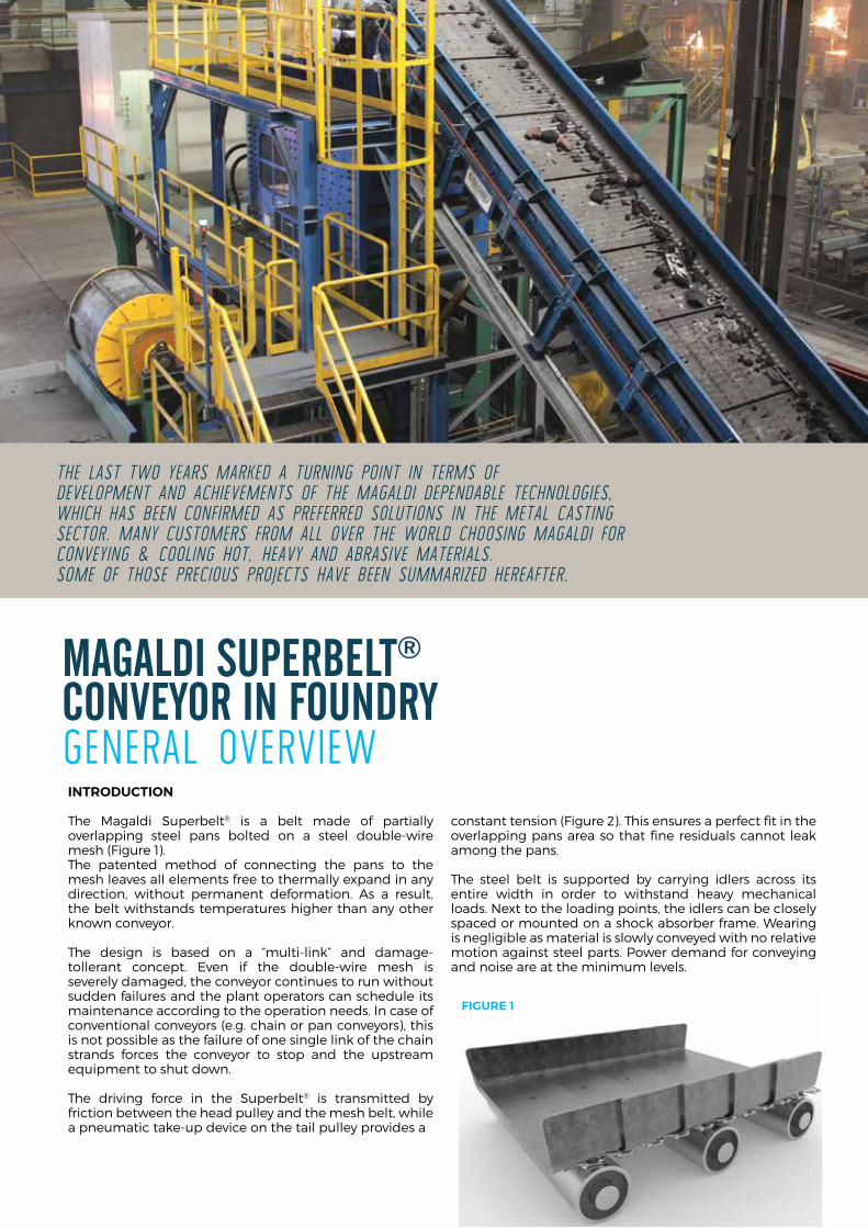
inTroducTion
The magaldi superbelt® is a belt made of partially overlapping steel pans bolted on a steel double-wire mesh (figure 1).The patented method of connecting the pans to the mesh leaves all elements free to thermally expand in any direction, without permanent deformation. as a result, the belt withstands temperatures higher than any other known conveyor.
The design is based on a “multi-link” and damage-tollerant concept. even if the double-wire mesh is severely damaged, the conveyor continues to run without sudden failures and the plant operators can schedule its maintenance according to the operation needs. in case of conventional conveyors (e.g. chain or pan conveyors), this is not possible as the failure of one single link of the chain strands forces the conveyor to stop and the upstream equipment to shut down.
The driving force in the superbelt® is transmitted by friction between the head pulley and the mesh belt, while a pneumatic take-up device on the tail pulley provides a
constant tension (figure 2). This ensures a perfect fit in the overlapping pans area so that fine residuals cannot leak among the pans.
The steel belt is supported by carrying idlers across its entire width in order to withstand heavy mechanical loads. next to the loading points, the idlers can be closely spaced or mounted on a shock absorber frame. Wearing is negligible as material is slowly conveyed with no relative motion against steel parts. Power demand for conveying and noise are at the minimum levels.
Magaldi SupErbElt® coNvEyor iN FouNdry general overview
FiGure 1
the last two years MarKeD a turning point in terMs of DevelopMent anD achieveMents of the MagalDi DepenDable technologies, which has been confirMeD as preferreD solutions in the Metal casting sector. Many custoMers froM all over the worlD choosing MagalDi for conveying & cooling hot, heavy anD abrasive Materials. soMe of those precious projects have been suMMarizeD hereafter.
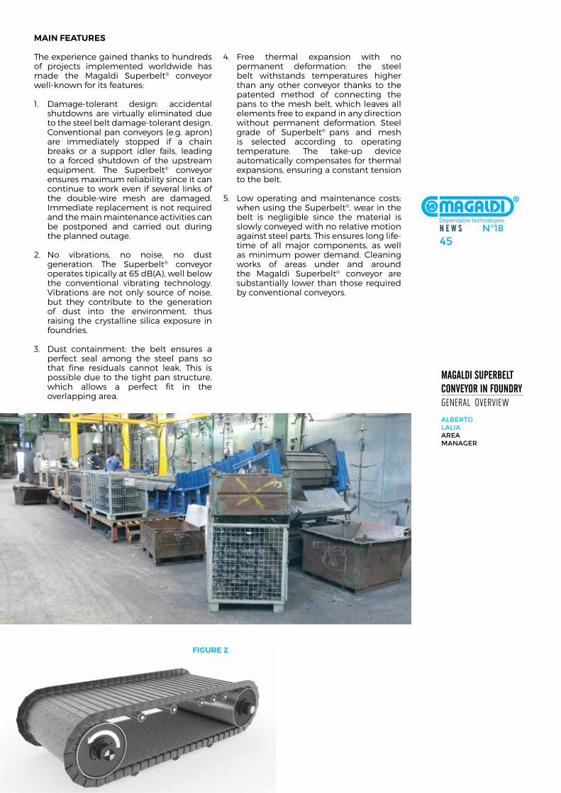
N E W S N°1845
Magaldi SupErbElt coNvEyor iN FouNdry general overview
alberto lalia area MaNager
Main FeaTures
The experience gained thanks to hundreds of projects implemented worldwide has made the magaldi superbelt® conveyor well-known for its features:
1. damage-tolerant design: accidental shutdowns are virtually eliminated due to the steel belt damage-tolerant design. conventional pan conveyors (e.g. apron) are immediately stopped if a chain breaks or a support idler fails, leading to a forced shutdown of the upstream equipment. The superbelt® conveyor ensures maximum reliability since it can continue to work even if several links of the double-wire mesh are damaged. immediate replacement is not required and the main maintenance activities can be postponed and carried out during the planned outage.
2. no vibrations, no noise, no dust generation. The superbelt® conveyor operates tipically at 65 dB(a), well below the conventional vibrating technology. Vibrations are not only source of noise, but they contribute to the generation of dust into the environment, thus raising the crystalline silica exposure in foundries.
3. dust containment: the belt ensures a perfect seal among the steel pans so that fine residuals cannot leak. This is possible due to the tight pan structure, which allows a perfect fit in the overlapping area.
4. free thermal expansion with no permanent deformation: the steel belt withstands temperatures higher than any other conveyor thanks to the patented method of connecting the pans to the mesh belt, which leaves all elements free to expand in any direction without permanent deformation. steel grade of superbelt® pans and mesh is selected according to operating temperature. The take-up device automatically compensates for thermal expansions, ensuring a constant tension to the belt.
5. low operating and maintenance costs: when using the superbelt®, wear in the belt is negligible since the material is slowly conveyed with no relative motion against steel parts. This ensures long life-time of all major components, as well as minimum power demand. cleaning works of areas under and around the magaldi superbelt® conveyor are substantially lower than those required by conventional conveyors.
FiGure 2
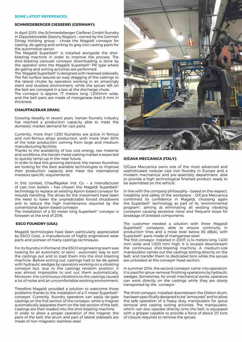
soMe laTesT reFerences:
schMiedeBerGer Giesserei (GerMany):
in april 2015, the schmiedeberger Gießerei Gmbh foundry in dippoldiswalde (saxony region) – owned by the German dihag holding group – chose the magaldi conveyor for casting, de-gating and sorting its grey iron casting parts for the automotive sector.The magaldi superbelt® is installed alongside the shot-blasting machine in order to improve the process. The shot-blasting carousel conveyor downloading is done by the operator onto the magaldi superbelt® Pr type where de-gating and sorting activities are performed.The magaldi superbelt® is designed with reversed sidewalls. The flat surface assures an easy dragging of the castings to the lateral chutes by operators working in an amazingly silent and dustless environment, while the sprues left on the belt are conveyed in a box at the discharge chute. The conveyor is approx. 17 meters long, 1,200mm wide, and the belt pans are made of manganese steel 8 mm in thickness.
chauFFaGekar (iran):
Growing steadily in recent years, iranian foundry industry has reached a production capacity able to meet the domestic market demand for cast parts.
currently, more than 1,250 foundries are active in ferrous and non-ferrous alloys production, with more than 80% of the total production coming from large and medium manufacturing facilities. Thanks to the availability of low cost energy, raw material and workforce, the iranian metal casting market is expected to quickly ramp-up in the near future. in order to face this growing demand, the iranian foundries are looking for the best available technologies to improve their production capacity and meet the international investors specific requirements.
in this context, chauffagekar ind. co. – a manufacturer of cast iron boilers – has chosen the magaldi superbelt® technology to replace an existing apron-based conveyor for moulds handling. The drives for the investment have been the need to lower the unpredictable forced shutdowns and to reduce the high maintenance required by the conventional apron-based conveyor.The installation of a 30 meter long superbelt® conveyor is foreseen at the end of 2016.
esco Foundry (usa):
magaldi technologies have been particularly appreciated by esco corp., a manufacturer of highly engineered wear parts and pioneer of many castings techniques.
for its foundry in Portland, the esco engineering team was looking for an automatic or semi - automatic way to sort the castings out and to load them into the shot-blasting machine. Before sorting out, castings had to be de-gated with hydraulic wedges by operators working on a vibrating conveyor but, due to the castings random position, it was almost impossible to sort out them automatically. moreover, the continuous vibrations to the castings caused a lot of noise and an uncomfortable working environment.
Therefore magaldi provided a solution to overcome those problems thanks to the installation of a 11 meter superbelt® conveyor. currently, foundry operators can easily de-gate castings on the first section of the conveyor, while a magnet automatically separates them on the last section of the belt. castings are then loaded into the shot-blasting machine.in order to allow a proper operation of the magnet, the pans of the belt, the drum and part of lateral sidewalls are made of non-magnetic stainless steel.
o/cava Meccanica (iTaly):
o/cava meccanica owns one of the most advanced and sophisticated nodular cast iron foundry in europe and a modern mechanical and pre-assembly department, able to provide a high technological finished product, ready to be assembled on the vehicle.
in line with the company philosophy – based on the respect, liveability and safety of the workplace - o/cava meccanica confirmed its confidence in magaldi, choosing again the superbelt® technology as part of its “environmental program”, aiming at eliminating all existing vibrating conveyors causing excessive noise and frequent stops for breakage of stressed components.
The customer needed a solution with three magaldi superbelt® conveyors, able to ensure continuity in production lines and a noise level below 65 dB(a), with superbelt® pans made of manganese steel.The first conveyor, installed in 2007, is 14 meters long, 1,400 mm wide and 1,000 mm high. it is located downstream the continuous shot-blasting machine. a medium-size manipulator carries out the castings sorting directly on the belt, and transfer them to dedicated bins while the sprues are unloaded at the conveyor head section.
in summer 2014, the second conveyor came into operation. it is used for sprue-removal finishing operations by hydraulic wedges. sometimes, for small mechanical works, operators can work directly on the castings while they are slowly transported by the conveyor.
The third conveyor, installed downstream the didion drum, has been specifically designed to be “armoured” and to allow the safe operation of a heavy duty manipulator for sprue removal and casting sorting activities. The manipulator, which can also operate directly onto the belt, is equipped with a gripper capable to provide a force of about 20 tons of closure required to remove the sprues.
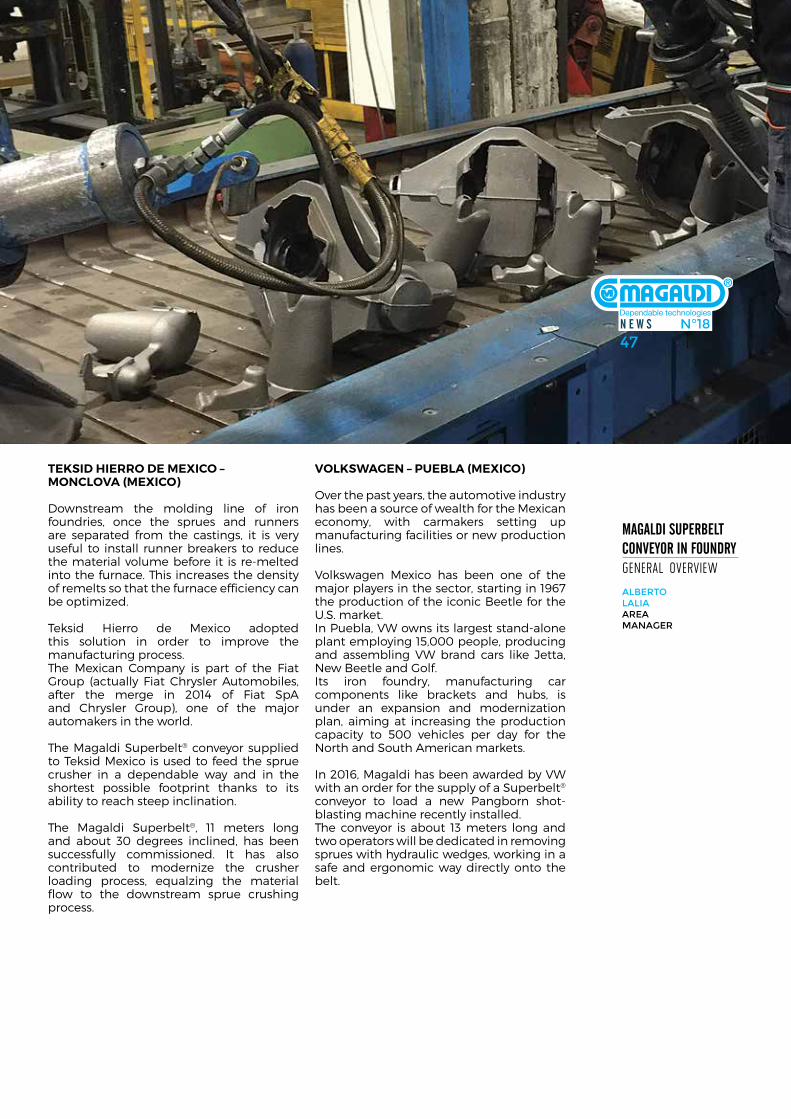
N E W S N°1847N E W S N°1847
Magaldi SupErbElt coNvEyor iN FouNdry general overview
alberto lalia area MaNager
Teksid hierro de Mexico – Monclova (Mexico)
downstream the molding line of iron foundries, once the sprues and runners are separated from the castings, it is very useful to install runner breakers to reduce the material volume before it is re-melted into the furnace. This increases the density of remelts so that the furnace efficiency can be optimized.
Teksid hierro de mexico adopted this solution in order to improve the manufacturing process.The mexican company is part of the fiat Group (actually fiat chrysler automobiles, after the merge in 2014 of fiat spa and chrysler Group), one of the major automakers in the world.
The magaldi superbelt® conveyor supplied to Teksid mexico is used to feed the sprue crusher in a dependable way and in the shortest possible footprint thanks to its ability to reach steep inclination.
The magaldi superbelt®, 11 meters long and about 30 degrees inclined, has been successfully commissioned. it has also contributed to modernize the crusher loading process, equalzing the material flow to the downstream sprue crushing process.
volksWaGen – pueBla (Mexico)
over the past years, the automotive industry has been a source of wealth for the mexican economy, with carmakers setting up manufacturing facilities or new production lines.
Volkswagen mexico has been one of the major players in the sector, starting in 1967 the production of the iconic Beetle for the u.s. market.in Puebla, VW owns its largest stand-alone plant employing 15,000 people, producing and assembling VW brand cars like Jetta, new Beetle and Golf. its iron foundry, manufacturing car components like brackets and hubs, is under an expansion and modernization plan, aiming at increasing the production capacity to 500 vehicles per day for the north and south american markets.
in 2016, magaldi has been awarded by VW with an order for the supply of a superbelt® conveyor to load a new Pangborn shot-blasting machine recently installed.The conveyor is about 13 meters long and two operators will be dedicated in removing sprues with hydraulic wedges, working in a safe and ergonomic way directly onto the belt.
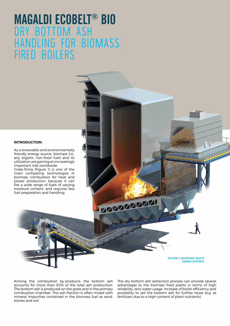
Magaldi EcobElt® biodry boTTom ash handling for biomass fired boilers
inTroducTion
as a renewable and environmentally friendly energy source, biomass (i.e., any organic non-fossil fuel) and its utilization are gaining an increasingly important role worldwide.Grate-firing (figure 1) is one of the main competing technologies in biomass combustion for heat and power production, because it can fire a wide range of fuels of varying moisture content, and requires less fuel preparation and handling.
among the combustion by-products, the bottom ash accounts for more than 50% of the total ash production. The bottom ash is produced on the grate and in the primary combustion chamber. This ash fraction is often mixed with mineral impurities contained in the biomass fuel as sand, stones and soil.
The dry bottom ash extraction process can provide several advantages to the biomass fired plants in terms of high reliability, zero water usage, increase of boiler efficiency and possibility to sell the bottom ash for further reuse (e.g. as fertilizers due to a high content of plant nutrients).
FiGure 1: BioMass GraTe FirinG sysTeM.
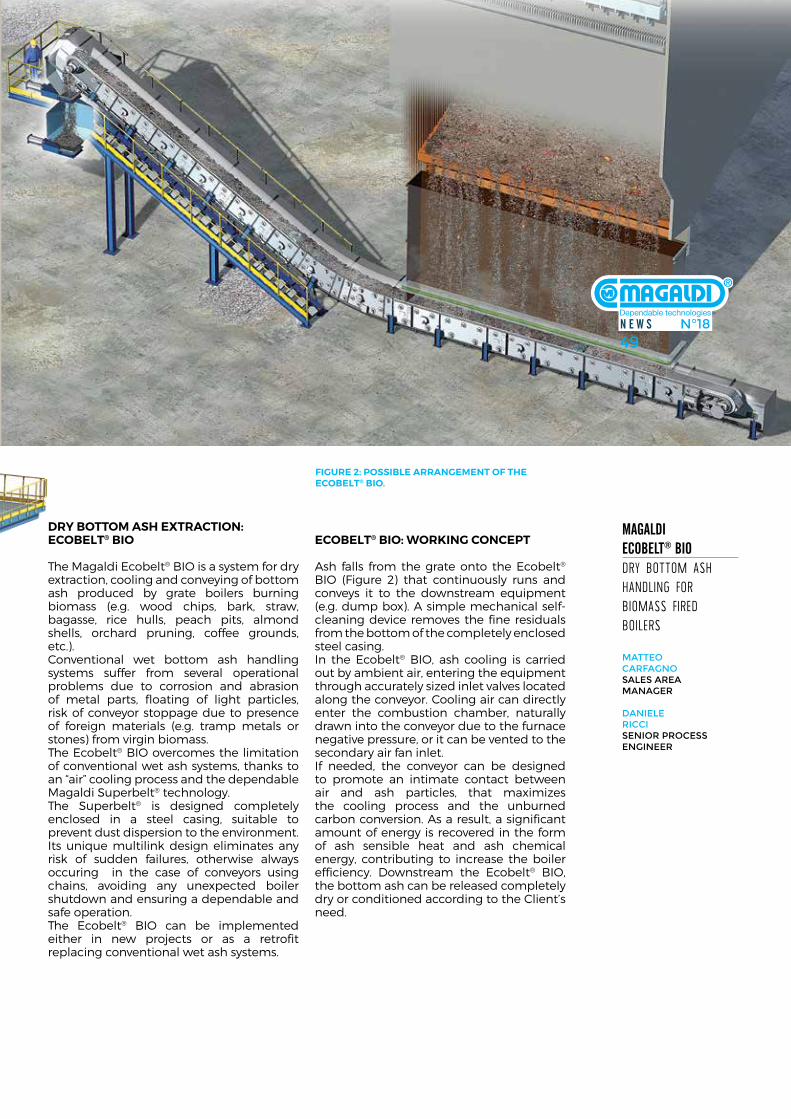
N E W S N°1849N E W S N°1849
FiGure 2: possiBle arranGeMenT oF The ecoBelT® Bio.
dry BoTToM ash exTracTion:ecoBelT® Bio
The magaldi ecobelt® Bio is a system for dry extraction, cooling and conveying of bottom ash produced by grate boilers burning biomass (e.g. wood chips, bark, straw, bagasse, rice hulls, peach pits, almond shells, orchard pruning, coffee grounds, etc.).conventional wet bottom ash handling systems suffer from several operational problems due to corrosion and abrasion of metal parts, floating of light particles, risk of conveyor stoppage due to presence of foreign materials (e.g. tramp metals or stones) from virgin biomass.The ecobelt® Bio overcomes the limitation of conventional wet ash systems, thanks to an “air” cooling process and the dependable magaldi superbelt® technology.The superbelt® is designed completely enclosed in a steel casing, suitable to prevent dust dispersion to the environment. its unique multilink design eliminates any risk of sudden failures, otherwise always occuring in the case of conveyors using chains, avoiding any unexpected boiler shutdown and ensuring a dependable and safe operation.The ecobelt® Bio can be implemented either in new projects or as a retrofit replacing conventional wet ash systems.
ecoBelT® Bio: WorkinG concepT
ash falls from the grate onto the ecobelt® Bio (figure 2) that continuously runs and conveys it to the downstream equipment (e.g. dump box). a simple mechanical self-cleaning device removes the fine residuals from the bottom of the completely enclosed steel casing.in the ecobelt® Bio, ash cooling is carried out by ambient air, entering the equipment through accurately sized inlet valves located along the conveyor. cooling air can directly enter the combustion chamber, naturally drawn into the conveyor due to the furnace negative pressure, or it can be vented to the secondary air fan inlet.if needed, the conveyor can be designed to promote an intimate contact between air and ash particles, that maximizes the cooling process and the unburned carbon conversion. as a result, a significant amount of energy is recovered in the form of ash sensible heat and ash chemical energy, contributing to increase the boiler efficiency. downstream the ecobelt® Bio, the bottom ash can be released completely dry or conditioned according to the client’s need.
Magaldi EcobElt® biodry boTTom ash handling for biomass fired boilers
Matteo CarfagNo sales area MaNager
daNiele riCCiseNior ProCess eNgiNeer
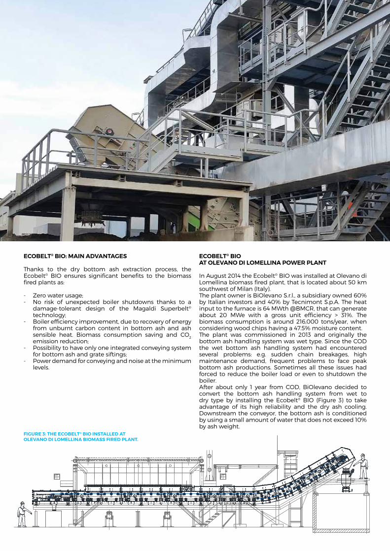
ecoBelT® Bio: Main advanTaGes
Thanks to the dry bottom ash extraction process, the ecobelt® Bio ensures significant benefits to the biomass fired plants as:
- Zero water usage;- no risk of unexpected boiler shutdowns thanks to a
damage-tolerant design of the magaldi superbelt® technology;
- Boiler efficiency improvement, due to recovery of energy from unburnt carbon content in bottom ash and ash sensible heat. Biomass consumption saving and co2 emission reduction;
- Possibility to have only one integrated conveying system for bottom ash and grate siftings;
- Power demand for conveying and noise at the minimum levels.
ecoBelT® Bio aT olevano di loMellina poWer planT
in august 2014 the ecobelt® Bio was installed at olevano di lomellina biomass fired plant, that is located about 50 km southwest of milan (italy).The plant owner is Biolevano s.r.l., a subsidiary owned 60% by italian investors and 40% by Tecnimont s.p.a. The heat input to the furnace is 64 mWth @Bmcr, that can generate about 20 mWe with a gross unit efficiency > 31%. The biomass consumption is around 216,000 tons/year, when considering wood chips having a 47.5% moisture content.The plant was commissioned in 2013 and originally the bottom ash handling system was wet type. since the cod the wet bottom ash handling system had encountered several problems: e.g. sudden chain breakages, high maintenance demand, frequent problems to face peak bottom ash productions. sometimes all these issues had forced to reduce the boiler load or even to shutdown the boiler.after about only 1 year from cod, Biolevano decided to convert the bottom ash handling system from wet to dry type by installing the ecobelt® Bio (figure 3) to take advantage of its high reliability and the dry ash cooling. downstream the conveyor, the bottom ash is conditioned by using a small amount of water that does not exceed 10% by ash weight.
FiGure 3: The ecoBelT® Bio insTalled aT olevano di loMellina BioMass Fired planT.
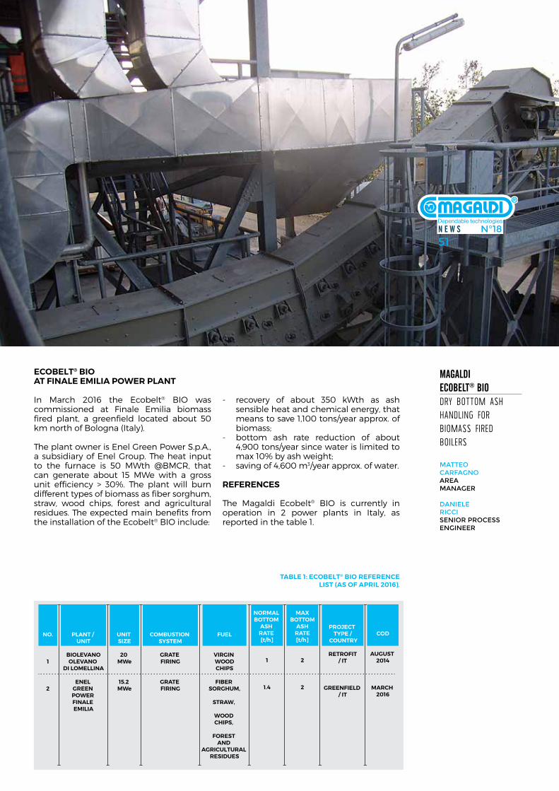
N E W S N°1851N E W S N°1851
ecoBelT® Bio aT Finale eMilia poWer planT
in march 2016 the ecobelt® Bio was commissioned at finale emilia biomass fired plant, a greenfield located about 50 km north of Bologna (italy).
The plant owner is enel Green Power s.p.a., a subsidiary of enel Group. The heat input to the furnace is 50 mWth @Bmcr, that can generate about 15 mWe with a gross unit efficiency > 30%. The plant will burn different types of biomass as fiber sorghum, straw, wood chips, forest and agricultural residues. The expected main benefits from the installation of the ecobelt® Bio include:
- recovery of about 350 kWth as ash sensible heat and chemical energy, that means to save 1,100 tons/year approx. of biomass;
- bottom ash rate reduction of about 4,900 tons/year since water is limited to max 10% by ash weight;
- saving of 4,600 m3/year approx. of water.
reFerences
The magaldi ecobelt® Bio is currently in operation in 2 power plants in italy, as reported in the table 1.
Magaldi EcobElt® biodry boTTom ash handling for biomass fired boilers
Matteo CarfagNo area MaNager
daNiele riCCiseNior ProCess eNgiNeer
NO.
1
2
PLANT / UNIT
BIOLEVANOOLEVANO
DI LOMELLINA
ENEL GREEN POWER FINALE EMILIA
UNIT SIZE
20 MWe
15.2 MWe
COMBUSTION SYSTEM
GRATE FIRING
GRATE FIRING
FUEL
VIRGIN WOODCHIPS
FIBER SORGHUM,
STRAW,
WOOD CHIPS,
FOREST AND
AGRICULTURAL RESIDUES
PROJECT TYPE /
COUNTRY
RETROFIT/ IT
GREENFIELD / IT
COD
AUGUST 2014
MARCH 2016
NORMAL BOTTOM
ASH RATE [t/h]
1
1.4
MAXBOTTOM
ASHRATE[t/h]
2
2
TaBle 1: ecoBelT® Bio reFerence lisT (as oF april 2016).
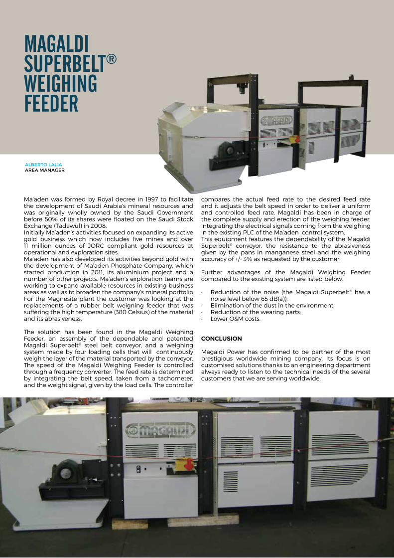
Magaldi SupErbElt®
WEighiNg FEEdEr
ma’aden was formed by royal decree in 1997 to facilitate the development of saudi arabia’s mineral resources and was originally wholly owned by the saudi Government before 50% of its shares were floated on the saudi stock exchange (Tadawul) in 2008.initially ma’aden’s activities focused on expanding its active gold business which now includes five mines and over 11 million ounces of Jorc compliant gold resources at operational and exploration sites. ma’aden has also developed its activities beyond gold with the development of ma’aden Phosphate company, which started production in 2011, its aluminium project and a number of other projects. ma’aden’s exploration teams are working to expand available resources in existing business areas as well as to broaden the company’s mineral portfoliofor the magnesite plant the customer was looking at the replacements of a rubber belt weigning feeder that was suffering the high temperature (380 celsius) of the material and its abrasiveness.
The solution has been found in the magaldi Weighing feeder, an assembly of the dependable and patented magaldi superbelt® steel belt conveyor, and a weighing system made by four loading cells that will continuously weigh the layer of the material transported by the conveyor. The speed of the magaldi Weighing feeder is controlled through a frequency converter. The feed rate is determined by integrating the belt speed, taken from a tachometer, and the weight signal, given by the load cells. The controller
compares the actual feed rate to the desired feed rate and it adjusts the belt speed in order to deliver a uniform and controlled feed rate. magaldi has been in charge of the complete supply and erection of the weighing feeder, integrating the electrical signals coming from the weighing in the existing Plc of the ma’aden control system.This equipment features the dependability of the magaldi superbelt® conveyor, the resistance to the abrasiveness given by the pans in manganese steel and the weighing accuracy of +/- 3% as requested by the customer.
further advantages of the magaldi Weighing feeder compared to the existing system are listed below:
• Reduction of thenoise (theMagaldi Superbelt® has a noise level below 65 dB(a));
• Eliminationofthedustintheenvironment;• Reductionofthewearingparts;• LowerO&Mcosts.
conclusion
magaldi Power has confirmed to be partner of the most prestigious worldwide mining company. its focus is on customised solutions thanks to an engineering department always ready to listen to the technical needs of the several customers that we are serving worldwide.
alberto lalia area MaNager

N E W S N°1853
in June 2015, after a fruitful meeting during Gifa 2015 exhibition, feralPi management involved magaldi in an important project for its new 200 t/h heavy metal scrap preparation process. The aim of the project was to put into operation the new metal separation system, equipped with the best available technologies within the end of 2016.The feralPi Group, one of the most important european iron & steel producers, is specialized in steel for construction industry. founded in 1968 in lonato del Garda (120 km far from milan), the feralPi
Group has grown up to reach a yearly production of more than 2 million tons of steel, employing 1,300 people through italy and europe. Their facilities are equipped with steel scrap shredding machines and metal separation systems.The mission of feralPi Group is manufacturing the highest quality of steel for construction industry in the most environmentally friendly way, reducing the emissions and the power demand, patenting and / or applying the best available technologies, thanks to an extensive r&d activity.
Magaldi SupErbElt® hdconTinuous sTeel scrap TransporTaTion
Matteo CarfagNo area MaNager
Magaldi SupErbElt® hd conTinuous sTeel scrap TransporTaTion
SECTION B-B
SECTION A-A
A
A
B
B
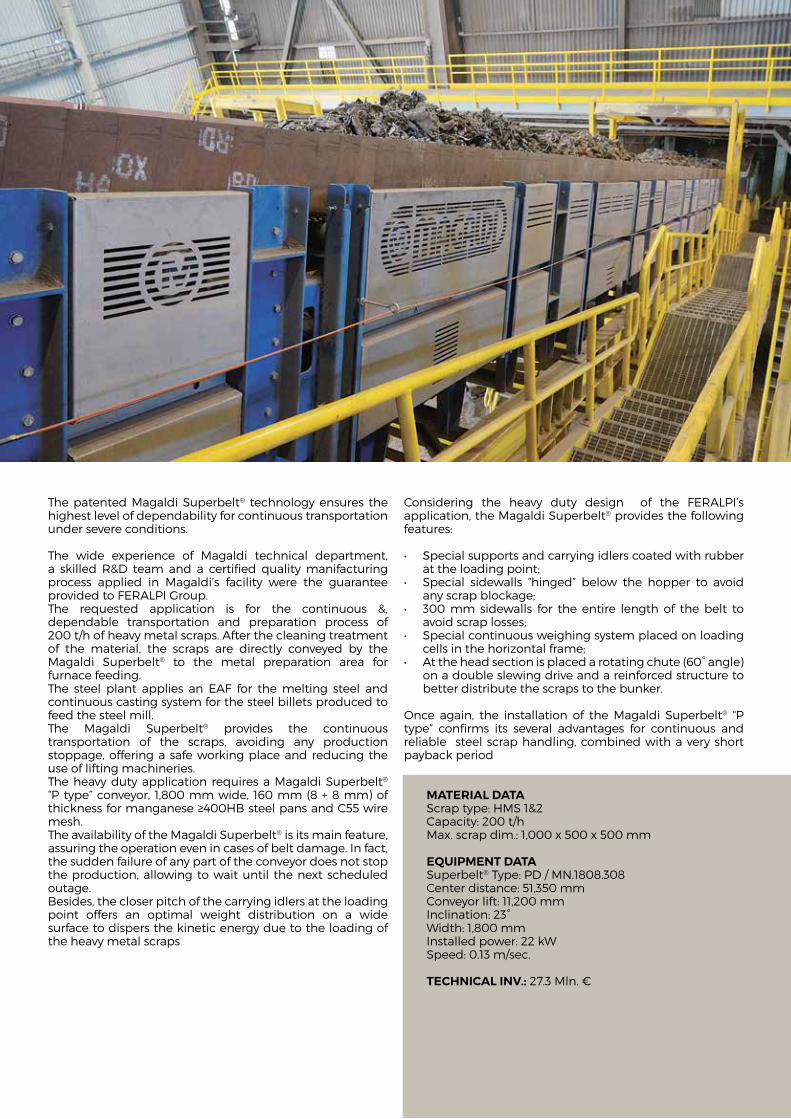
The patented magaldi superbelt® technology ensures the highest level of dependability for continuous transportation under severe conditions.
The wide experience of magaldi technical department, a skilled r&d team and a certified quality manifacturing process applied in magaldi’s facility were the guarantee provided to feralPi Group. The requested application is for the continuous &, dependable transportation and preparation process of 200 t/h of heavy metal scraps. after the cleaning treatment of the material, the scraps are directly conveyed by the magaldi superbelt® to the metal preparation area for furnace feeding.The steel plant applies an eaf for the melting steel and continuous casting system for the steel billets produced to feed the steel mill.The magaldi superbelt® provides the continuous transportation of the scraps, avoiding any production stoppage, offering a safe working place and reducing the use of lifting machineries.The heavy duty application requires a magaldi superbelt® “P type” conveyor, 1,800 mm wide, 160 mm (8 + 8 mm) of thickness for manganese ≥400hB steel pans and c55 wire mesh.The availability of the magaldi superbelt® is its main feature, assuring the operation even in cases of belt damage. in fact, the sudden failure of any part of the conveyor does not stop the production, allowing to wait until the next scheduled outage. Besides, the closer pitch of the carrying idlers at the loading point offers an optimal weight distribution on a wide surface to dispers the kinetic energy due to the loading of the heavy metal scraps
considering the heavy duty design of the feralPi’s application, the magaldi superbelt® provides the following features:
• Specialsupportsandcarryingidlerscoatedwithrubberat the loading point;
• Special sidewalls “hinged” below the hopper to avoidany scrap blockage;
• 300mmsidewalls for the entire lengthof thebelt toavoid scrap losses;
• Specialcontinuousweighingsystemplacedonloadingcells in the horizontal frame;
• Attheheadsectionisplacedarotatingchute(60°angle)on a double slewing drive and a reinforced structure to better distribute the scraps to the bunker.
once again, the installation of the magaldi superbelt® “P type” confirms its several advantages for continuous and reliable steel scrap handling, combined with a very short payback period
MaTerial daTascrap type: hms 1&2capacity: 200 t/hmax. scrap dim.: 1,000 x 500 x 500 mm
equipMenT daTasuperbelt® Type: Pd / mn.1808.308center distance: 51,350 mmconveyor lift: 11,200 mminclination: 23°Width: 1,800 mminstalled power: 22 kWspeed: 0.13 m/sec.
Technical inv.: 27.3 mln. €
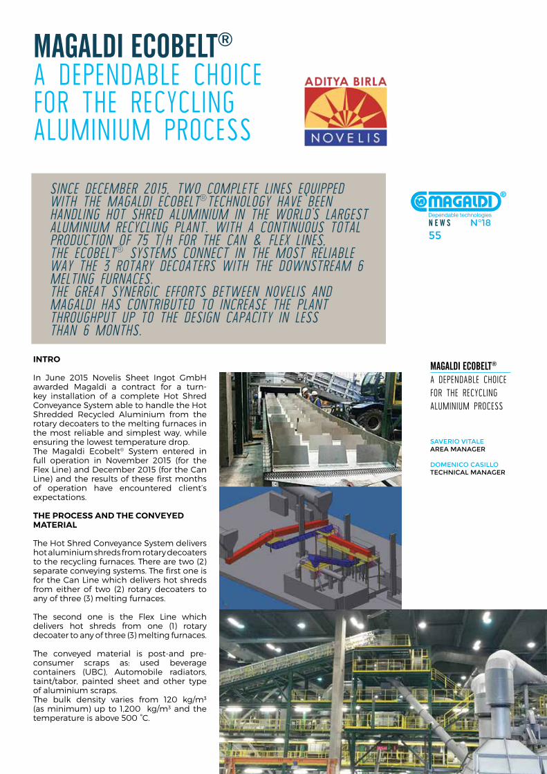
N E W S N°1855
inTro
in June 2015 novelis sheet ingot Gmbh awarded magaldi a contract for a turn-key installation of a complete hot shred conveyance system able to handle the hot shredded recycled aluminium from the rotary decoaters to the melting furnaces in the most reliable and simplest way, while ensuring the lowest temperature drop.The magaldi ecobelt® system entered in full operation in november 2015 (for the flex line) and december 2015 (for the can line) and the results of these first months of operation have encountered client‘s expectations.
The process and The conveyed MaTerial
The hot shred conveyance system delivers hot aluminium shreds from rotary decoaters to the recycling furnaces. There are two (2) separate conveying systems. The first one is for the can line which delivers hot shreds from either of two (2) rotary decoaters to any of three (3) melting furnaces.
The second one is the flex line which delivers hot shreds from one (1) rotary decoater to any of three (3) melting furnaces.
The conveyed material is post-and pre-consumer scraps as: used beverage containers (uBc), automobile radiators, taint/tabor, painted sheet and other type of aluminium scraps. The bulk density varies from 120 kg/m³ (as minimum) up to 1,200 kg/m³ and the temperature is above 500 °c.
Magaldi EcobElt® a dependable choicefor The recycling aluminium process
Magaldi EcobElt® a dependable choice for The recycling aluminium process
saverio vitalearea MaNager
doMeNiCo CasilloteChNiCal MaNager
since DeceMber 2015, two coMplete lines equippeD with the MagalDi ecobelt®technology have been hanDling hot shreD aluMiniuM in the worlD’s largest aluMiniuM recycling plant. with a continuous total proDuction of 75 t/h for the can & flex lines,the ecobelt® systeMs connect in the Most reliable way the 3 rotary Decoaters with the DownstreaM 6 Melting furnaces.the great synergic efforts between novelis anD MagalDi has contributeD to increase the plant throughput up to the Design capacity in less than 6 Months.
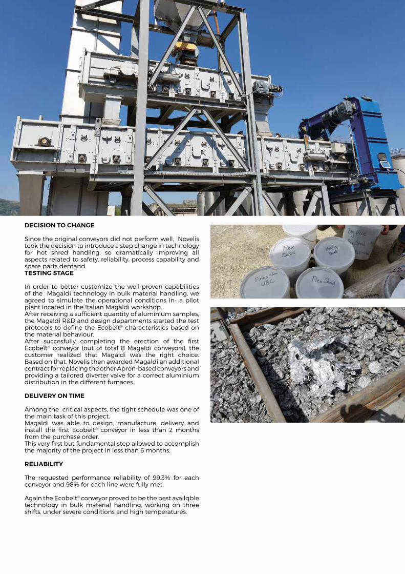
decision To chanGe
since the original conveyors did not perform well, novelis took the decision to introduce a step change in technology for hot shred handling, so dramatically improving all aspects related to safety, reliability, process capability and spare parts demand. TesTinG sTaGe
in order to better customize the well-proven capabilities of the magaldi technology in bulk material handling, we agreed to simulate the operational conditions in- a pilot plant located in the italian magaldi workshop.after receiving a sufficient quantity of aluminium samples, the magaldi r&d and design departments started the test protocols to define the ecobelt® characteristics based on the material behaviour. after succesfully completing the erection of the first ecobelt® conveyor (out of total 8 magaldi conveyors), the customer realized that magaldi was the right choice. Based on that, novelis then awarded magaldi an additional contract for replacing the other apron-based conveyors and providing a tailored diverter valve for a correct aluminium distribution in the different furnaces.
delivery on TiMe
among the critical aspects, the tight schedule was one of the main task of this project. magaldi was able to design, manufacture, delivery and install the first ecobelt® conveyor in less than 2 months from the purchase order.This very first but fundamental step allowed to accomplish the majority of the project in less than 6 months.
reliaBiliTy
The requested performance reliability of 99.3% for each conveyor and 98% for each line were fully met.
again the ecobelt® conveyor proved to be the best availqble technology in bulk material handling, working on three shifts, under severe conditions and high temperatures.
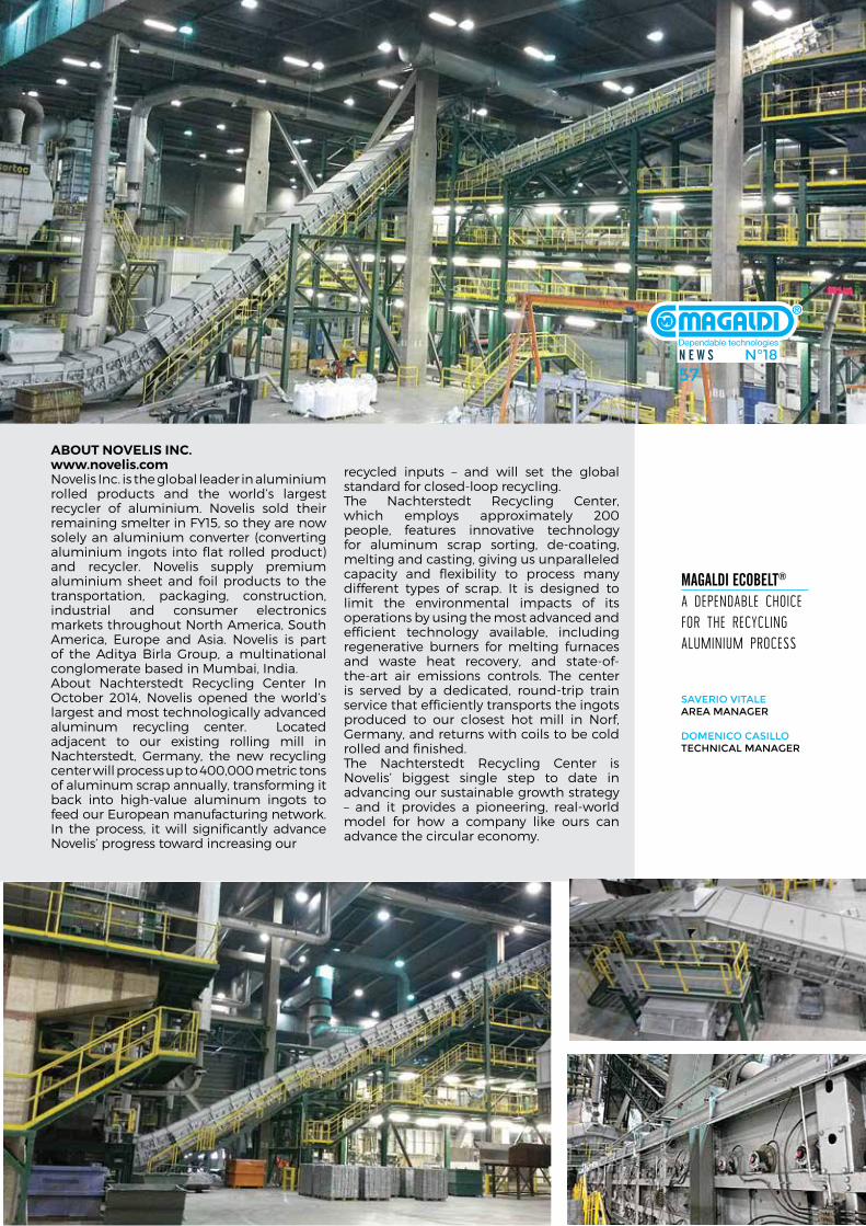
N E W S N°1857
Magaldi EcobElt® a dependable choice for The recycling aluminium process
saverio vitalearea MaNager
doMeNiCo CasilloteChNiCal MaNager
aBouT novelis inc.www.novelis.comnovelis inc. is the global leader in aluminium rolled products and the world’s largest recycler of aluminium. novelis sold their remaining smelter in fY15, so they are now solely an aluminium converter (converting aluminium ingots into flat rolled product) and recycler. novelis supply premium aluminium sheet and foil products to the transportation, packaging, construction, industrial and consumer electronics markets throughout north america, south america, europe and asia. novelis is part of the aditya Birla Group, a multinational conglomerate based in mumbai, india.about nachterstedt recycling center in october 2014, novelis opened the world’s largest and most technologically advanced aluminum recycling center. located adjacent to our existing rolling mill in nachterstedt, Germany, the new recycling center will process up to 400,000 metric tons of aluminum scrap annually, transforming it back into high-value aluminum ingots to feed our european manufacturing network. in the process, it will significantly advance novelis’ progress toward increasing our
recycled inputs – and will set the global standard for closed-loop recycling.The nachterstedt recycling center, which employs approximately 200 people, features innovative technology for aluminum scrap sorting, de-coating, melting and casting, giving us unparalleled capacity and flexibility to process many different types of scrap. it is designed to limit the environmental impacts of its operations by using the most advanced and efficient technology available, including regenerative burners for melting furnaces and waste heat recovery, and state-of-the-art air emissions controls. The center is served by a dedicated, round-trip train service that efficiently transports the ingots produced to our closest hot mill in norf, Germany, and returns with coils to be cold rolled and finished. The nachterstedt recycling center is novelis’ biggest single step to date in advancing our sustainable growth strategy – and it provides a pioneering, real-world model for how a company like ours can advance the circular economy.
N E W S N°1857
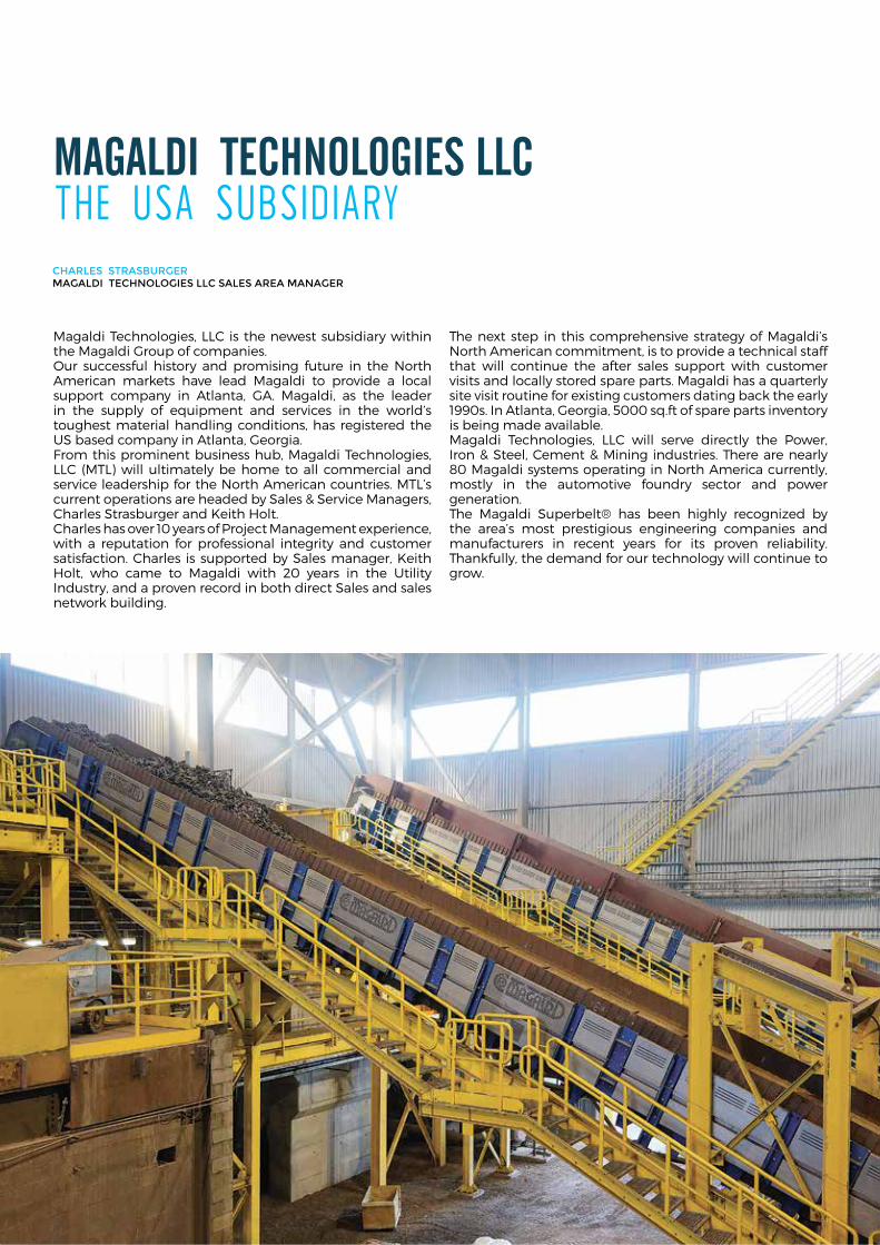
Magaldi tEchNologiES llc The usa subsidiary
magaldi Technologies, llc is the newest subsidiary within the magaldi Group of companies. our successful history and promising future in the north american markets have lead magaldi to provide a local support company in atlanta, Ga. magaldi, as the leader in the supply of equipment and services in the world’s toughest material handling conditions, has registered the us based company in atlanta, Georgia. from this prominent business hub, magaldi Technologies, llc (mTl) will ultimately be home to all commercial and service leadership for the north american countries. mTl’s current operations are headed by sales & service managers, charles strasburger and keith holt. charles has over 10 years of Project management experience, with a reputation for professional integrity and customer satisfaction. charles is supported by sales manager, keith holt, who came to magaldi with 20 years in the utility industry, and a proven record in both direct sales and sales network building.
The next step in this comprehensive strategy of magaldi’s north american commitment, is to provide a technical staff that will continue the after sales support with customer visits and locally stored spare parts. magaldi has a quarterly site visit routine for existing customers dating back the early 1990s. in atlanta, Georgia, 5000 sq.ft of spare parts inventory is being made available. magaldi Technologies, llc will serve directly the Power, iron & steel, cement & mining industries. There are nearly 80 magaldi systems operating in north america currently, mostly in the automotive foundry sector and power generation. The magaldi superbelt® has been highly recognized by the area’s most prestigious engineering companies and manufacturers in recent years for its proven reliability. Thankfully, the demand for our technology will continue to grow.
Charles strasburger Magaldi teChNologies llC sales area MaNager
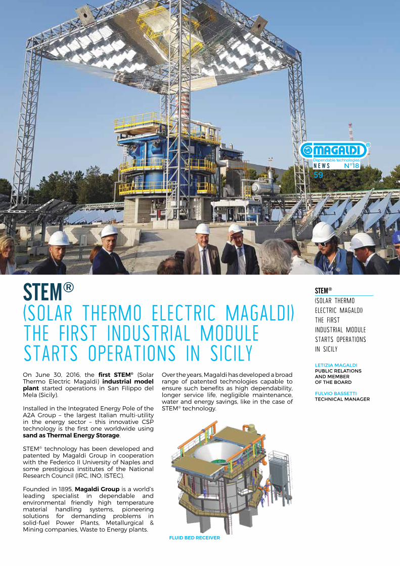
N E W S N°1859N E W S N°1859
on June 30, 2016, the first sTeM® (solar Thermo electric magaldi) industrial model plant started operations in san filippo del mela (sicily).
installed in the integrated energy Pole of the a2a Group – the largest italian multi-utility in the energy sector – this innovative csP technology is the first one worldwide using sand as Thermal energy storage.
sTem® technology has been developed and patented by magaldi Group in cooperation with the federico ii university of naples and some prestigious institutes of the national research council (irc, ino, isTec).
founded in 1895, Magaldi Group is a world’s leading specialist in dependable and environmental friendly high temperature material handling systems, pioneering solutions for demanding problems in solid-fuel Power Plants, metallurgical & mining companies, Waste to energy plants.
over the years, magaldi has developed a broad range of patented technologies capable to ensure such benefits as high dependability, longer service life, negligible maintenance, water and energy savings, like in the case of sTem® technology.
StEM®
(solar Thermo elecTric magaldi)The firsT indusTrial module sTarTs operaTions in sicily
letizia Magaldi PubliC relatioNs aNd MeMber of the board fulvio bassetti teChNiCal MaNager
StEM® (solar Thermo elecTric magaldi)The firsT indusTrial module sTarTs operaTions in sicily
N E W S N°1859
Fluid Bed receiver
SOLAR FIELDSHELIOSTATS
SECONDARYREFLECTOR
CAVITY
STORAGE
HEAT EXCHANGER
STEAM WATERNETWORK
THERMAL CYCLE
ELECTRICITY HEATRECEIVER
This new csp system with Tes (Thermal energy storage) is able to collect solar energy – through a solar field made of heliostats – and convert it into thermal energy to be stored and extracted when desired.
sTem® is based on modular steam generator units (sGu) for power production and thermal energy storage. several modules can be combined together to produce the superheated steam flow rate (at around 500°c), to be used to generate electricity or heat.
solar radiation captured by heliostats field is concentrated on a secondary reflector (beam down) and subsequently focused into a receiver, positioned at ground level.The receiver is based on a fluidized bed technology: 270 tons of fluidized sand, at an operating temperature of 550-650°c, are used to effectively transfer and store the solar thermal energy. up to 8.2 mWh thermal energy can be stored per module, thus allowing the release of the required energy at night, or in absence of sun radiation (e.g. 2 mWt for 4 hours, 1.3 mWt for 6 hours, or 0.8 mWt for 10 hours).
different configurations of sTem® can be applied, according to the customer need.
sTeM® planT overvieW - a2a inTeGraTed enerGy disTricT san Filippo del Mela, sicily (iTaly)
sGu concepTual scheMe
N E W S N°1861
sTeM® as solar accuMulaTor inTeGraTed To a pv planT
sTem® is an ideal component to be combined with existing or dedicated PV plants to grant continuity of green power production during night time.during the day, electric power is directly produced from sunlight with the PV plant, which also feeds the sTem® auxiliaries, allowing solar energy to be effectively stored in the fluidized bed receiver.
The fluidized bed receiver, in this way, works as a Tes of solar power, that can be used during the night for steam or power generation.
in a typical arrangement, each sTem® module is equipped with 390 heliostats (surface 7 m2 each), rated at an input solar power of 1.05 thermal mW, used for Thermal energy storage. land occupation of one module is approx. 12000 m2. different values of input solar power can be obtained by different sizes of the heliostats field.
as an example, considering a sTem® system composed of 10 modules, the expected generation during the night of net energy per year can be calculated as follows (assuming a 28% Power Block efficiency):
StEM®
(solar Thermo elecTric magaldi)The firsT indusTrial module sTarTs operaTions in sicily
letizia Magaldi PubliC relatioNs aNd MeMber of the board fulvio bassetti teChNiCal MaNager
STEM STEM CYCLE
PV PLANT INVERTER SMART GRIDCTRL INTERFACE ELECTRICAL LOAD
DIESEL GENERATOR
sTeM® inTeGraTed sysTeM
SGU SGU
SGU SGU
SGU SGU
FROM SUN TO STEAM
TURBINE AND ELECTRICAL GENERATOR
THERMAL USE
sTeM® Modular conFiGuraTion
DNI=1920 kwh/m2/year – South Italy 4550 Mwhe
DNI=2700 kwh/m2/year – Australia 6500 Mwhe
DNI=3200 kwh/m2/year – Chile 7700 Mwhe
sTeM® planT
sTeM® key sTrenGThs:
• dependaBiliTy: The simple operational process and the modular configuration give sTem® a competitive advantage over other csP technologies. even if one module is under maintenance, the other modules guarantee continuity to the production of steam.
• FlexiBiliTy: fluidized bed technology using sand as storage medium and the possibility to connect the modules in parallel or in series enable the system to generate electricity according to the demand load.
• Modularity: The base modules can be combined together to meet the required power demand. it is possible to add modules at a later stage, in case demand increases.
• hyBridiZaTion: sTem® technology can be integrated with both renewable and fossil fuel plants, to guarantee a continuous operation, day and night, year-round. The receiver is designed to also allow the combustion of low heating value fuels, such as biogas.
• Cogeneration: high temperature steam generated can be used for district heating and cooling, water desalinization, greenhouses.
• environMental friendliness: sTem® technology only uses absolute eco-friendly materials: glass for heliostats, steel for structures and sand for thermal storage, so that, even in case of decommissioning or at the end of its working life, all materials are completely recyclable.
• longserviCelife:sTem® system is almost static and it is designed to be operational for decades. Batteries, on the other hand, need to be substituted after a certain number of cycles.
• ideal solution for reMote areas: sTem® operates locally on demand without the need to build large power plants and expensive distribution grids.
sTem® technology is particularly suitable to cover the energy needs in remote sites without grid connection.
The great availability of the heat storage and the flexibility of production makes it possible to cover energy needs such as desalination of water, air conditioning and production of industrial steam, thus sustaining the economic and social growth of isolated areas.
compared to existing csP technologies, sTem® introduces two main innovative elements. first of all, the modularity (it’s to say the combination of a variable number of solar generation units) allows to realize generation systems of different configuration, power and capability. additional modules can be installed at a later stage, shall the power demand increase. But the main feature is its ability to store the solar energy and deliver it when needed, even at night or in cloudy periods.
moreover, the absolute lack of poisonous emissions into the environment (both in case of normal operation or failures) as well as the non-use of cooling water and any chemicals, makes sTem® technology the best way to produce green energy in remote zones.
even from the standpoint of the landscape, sTem® confirms its commitment towards the environment. in fact, compared to traditional Power Tower systems, sTem® does not have a huge visual impact since its highest structure does not exceed the height of 22 m meanwhile other csP tower systems reach over 100 m.

The inForMaTion conTained herein is provided For adverTisinG and General inForMaTion purposes only, and is noT inTended or To Be consTrued as a WarranTy, an oFFer, or any
represenTaTion oF conTracTual or oTher leGal responsiBiliTy.inTernaTional paTenTs pendinG. copyriGhT © 2016 MaGaldi. all riGhTs reserved
copyriGhT © 2016 MaGaldi. all riGhTs reserved
MaGaldi Group
26, PiaZZa di PieTra 00186 romaiTalY
head office219, Via irno84135 salernoiTalY
Ph +39 089 688 111faX +39 089 481 766
e-mail:
MaGaldi poWer pTy lTd
c/o accru leVel 6 1 chifleY sQuare 2000 sYdneY nsWausTralia
e-mail:
MaGaldi poWer GMBh
BoschsTr. 10 73734 esslinGenGermanY
Ph +49 711 93150 340 faX +49 711 93150 345
e-mail:
MaGaldi poWer india pvT lTd
flaT 8, 4Th floor147 lake Gardens 700 045 kolkaTa india
Ph +919830808228faX +919434748228
e-mail:
MaGaldi TechnoloGies llc
370 GreaT souThWesT PrkWY suiTe B aTlanTa Ga 30336 usa
Ph +1 800 620 6921
e-mail:
magaldiusa@ magaldi.com
www.magaldi.com
Gr
ap
hic
de
siG
n B
y l
uc
io l
uo
nG
o -
WW
W.l
uc
iolu
on
Go
.co
M


![Manual do participante 03[1].09.07 - cedca.pr.gov.br · Jacqueline Marçal Micali Ana Lúcia Conde SEJU Tamara Enke ... Luciana Magaldi Johansen ... OAB – CONSULTORES](https://img.pdfslide.net/doc/110x75/5bfab18709d3f240728b9b00/manual-do-participante-0310907-cedcaprgovbr-jacqueline-marcal-micali.jpg)