Embed Size (px)
DESCRIPTION
This power point presents essentials of technical drawing. Why/how...Full credit to the authorBhuiyan Shameem Mahmood.What are the main drivers, methods...What are the basic rules and where and how to access the standards that govern the Technical Drawing (Drafting).
Citation preview

Chapter 1
Overview of an Engineering Drawing
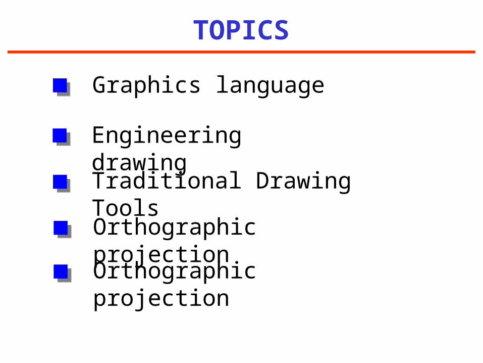
TOPICS
Traditional Drawing Tools
Orthographic projection
Graphics language
Engineering drawing
Orthographic projection

GRAPHICS LANGUAGE

1. Try to write a description of this object.
2. Test your written description by having someone attempt to make a sketch from your description.
Effectiveness of Graphics Language
The word languages are inadequate for describing the
size, shape and features completely as well as
concisely.
You can easily understand that …
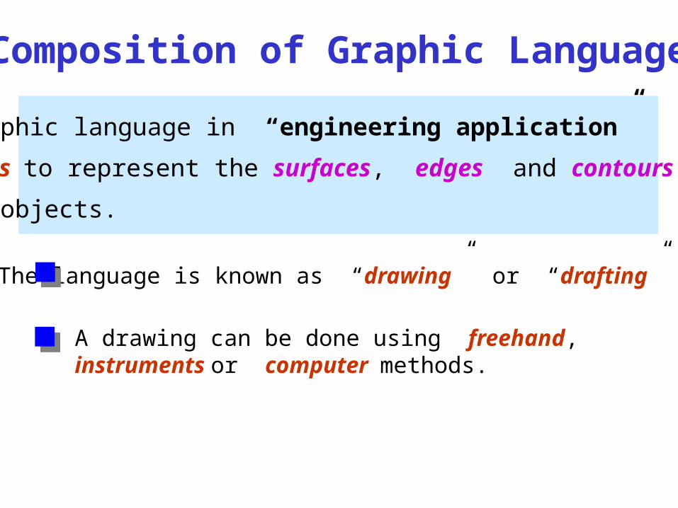
Graphic language in “engineering application” use
lines to represent the surfaces, edges and contours
of objects.
A drawing can be done using freehand, instruments or computer methods.
Composition of Graphic Language
The language is known as “drawing” or “drafting” .
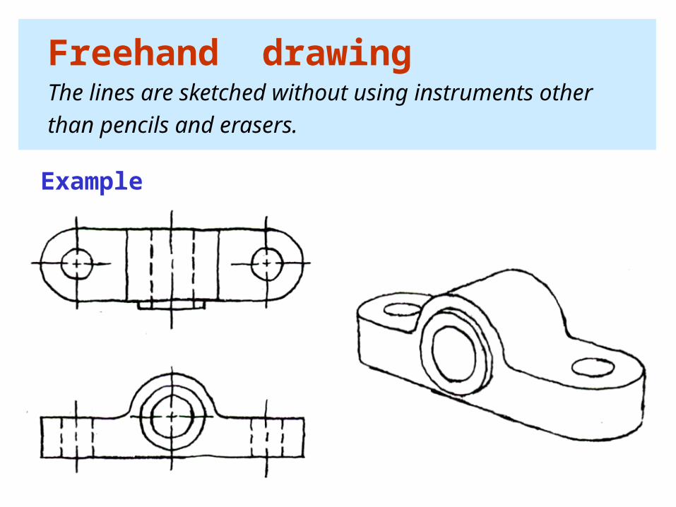
Freehand drawing The lines are sketched without using instruments other
than pencils and erasers.
Example

Instrument drawing Instruments are used to draw straight lines, circles, and
curves concisely and accurately. Thus, the drawings are
usually made to scale.
Example

Computer drawing The drawings are usually made by commercial software
such as AutoCAD, solid works etc.
Example

Engineering Drawing
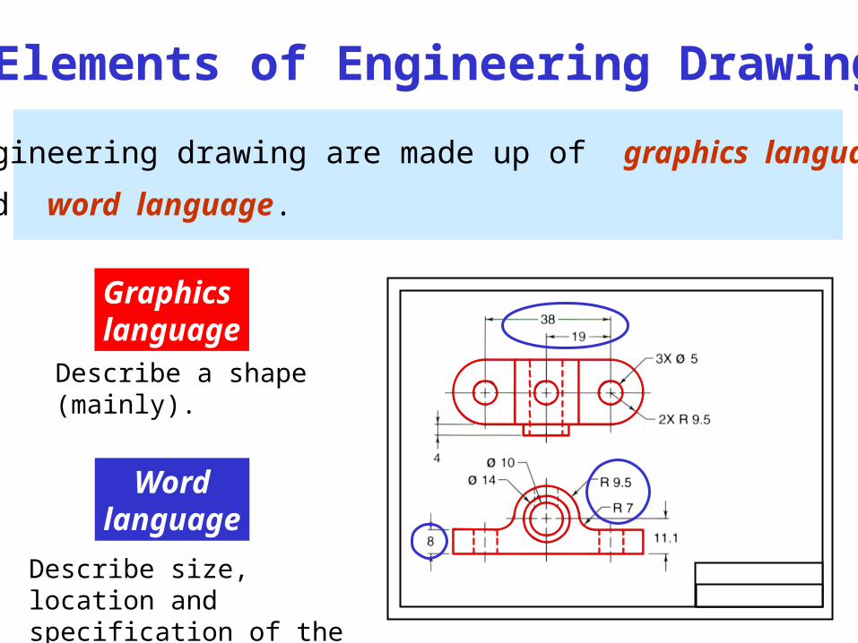
Elements of Engineering Drawing
Engineering drawing are made up of graphics language
and word language.
Graphicslanguage
Describe a shape(mainly).
Wordlanguage
Describe size, location andspecification of the object.

Traditional Drawing Tools
Traditional Drawing Tools
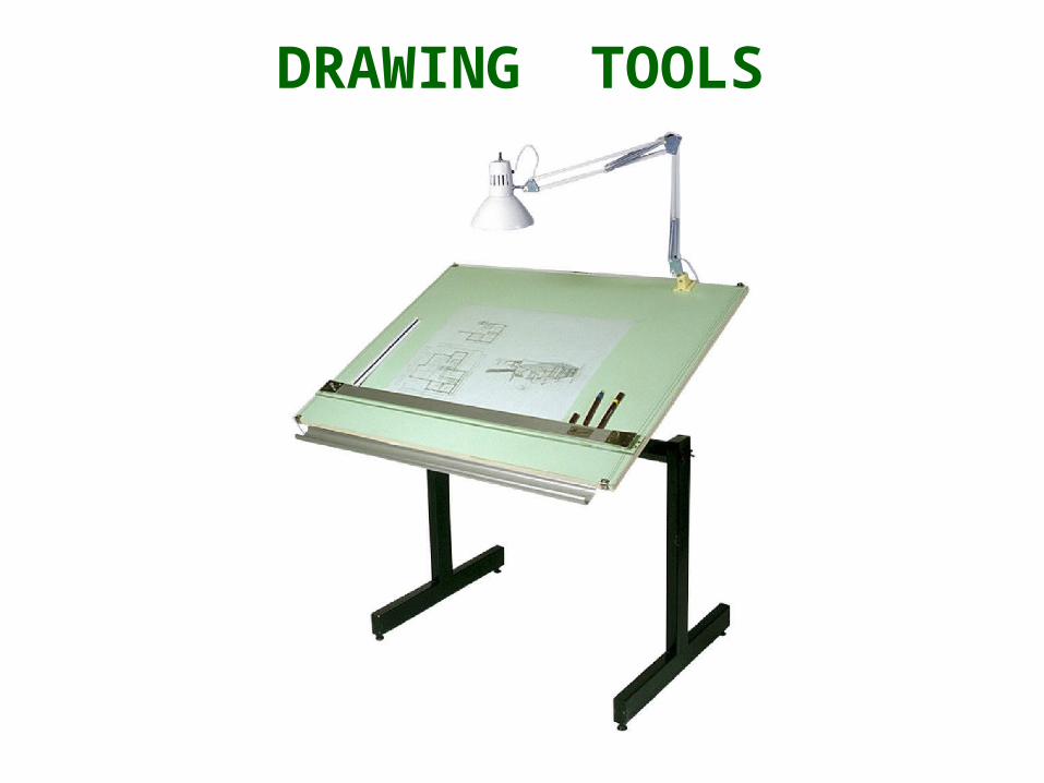
DRAWING TOOLS

1. Drawing Board
2. Mini Drafter
DRAWING TOOLS

3. T-Square 4. Triangles
DRAWING TOOLS
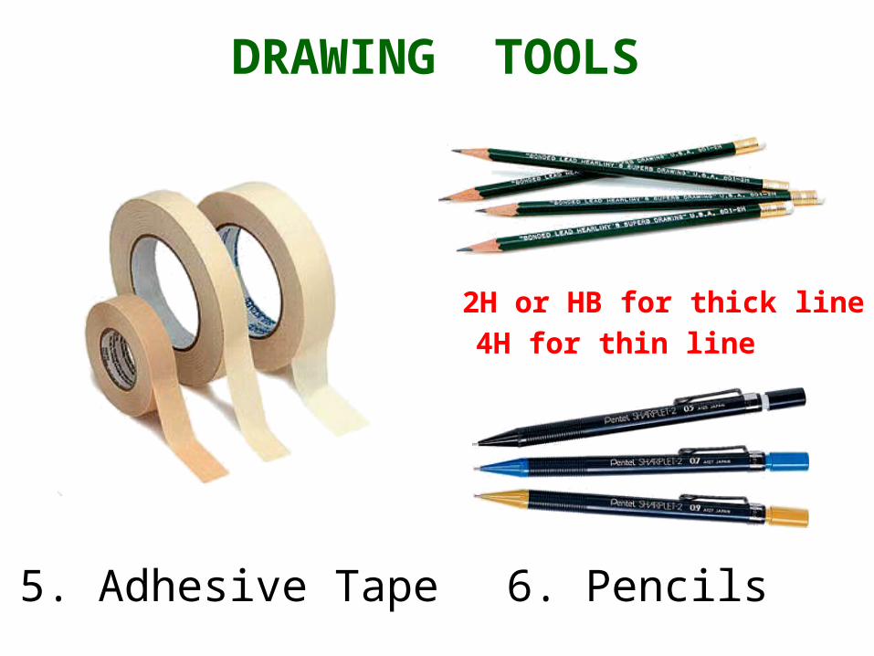
5. Adhesive Tape 6. Pencils
2H or HB for thick line4H for thin line
DRAWING TOOLS

7. Protector 8. Scale
DRAWING TOOLS

9. Roller Scale 10. French curve
DRAWING TOOLS

11. Sandpaper 12. Compass
DRAWING TOOLS

13. Pencil Eraser 14. Erasing Shield
DRAWING TOOLS

15. Circle Template 16. Drawing Clip
DRAWING TOOLS

17. Sharpener 18. Clean paper
DRAWING TOOLS

PROJECTION METHOD

PROJECTION THEORY
The projection theory is based on two variables:
1) Line of sight
2) Plane of projection (image plane or picture plane)
The projection theory is used to graphically represent
3-D objects on 2-D media (paper, computer screen).

PROJECTION METHOD
Perspective
Oblique Orthographic
Axonometric Multiview
Parallel
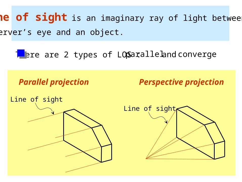
Line of sight is an imaginary ray of light between an
observer’s eye and an object.
Line of sight
Parallel projection
Line of sight
Perspective projection
There are 2 types of LOS : parallel convergeand

Plane of projection is an imaginary flat plane which
the image is created.
The image is produced by connecting the points where
the LOS pierce the projection plane.
Parallel projection Perspective projection
Plane of projection Plane of projection

Disadvantage ofPerspective Projection
Perspective projection is not
used by engineer for manu-
facturing of parts, because
1) It is difficult to create.
2) It does not reveal exact
shape and size.Width is distorted

Orthographic Projection
Orthographic Projection

5
Orthographic projection is a parallel projection technique
in which the parallel lines of sight are perpendicular to the
projection plane
MEANING
Object views from top
Projection plane
1
2
3
4
51 2 3 4

ORTHOGRAPHIC VIEWOrthographic view depends on relative position of the object
to the line of sight.
Two dimensions of anobject is shown.
Three dimensions of an object is shown.
Rotate
Tilt
More than one view is neededto represent the object.
Multiview drawing
Axonometric drawing

Orthographic projection technique can produce either
1. Multiview drawing that each view show an object in two dimensions.
2. Axonometric drawing that show all three dimensions of an object in one view.
Both drawing types are used in technical drawing for
communication.
NOTES
ORTHOGRAPHIC VIEW

Axonometric (Isometric) Drawing
Easy to understand
Right angle becomes obtuse angle.
Circular hole becomes ellipse.
Distortions of shape and size in isometric drawing
Advantage
Disadvantage Shape and angle distortion
Example

Multiview Drawing
It represents accurate shape and size.Advantage
Disadvantage Require practice in writing and reading.
Multiviews drawing (2-view drawing)Example
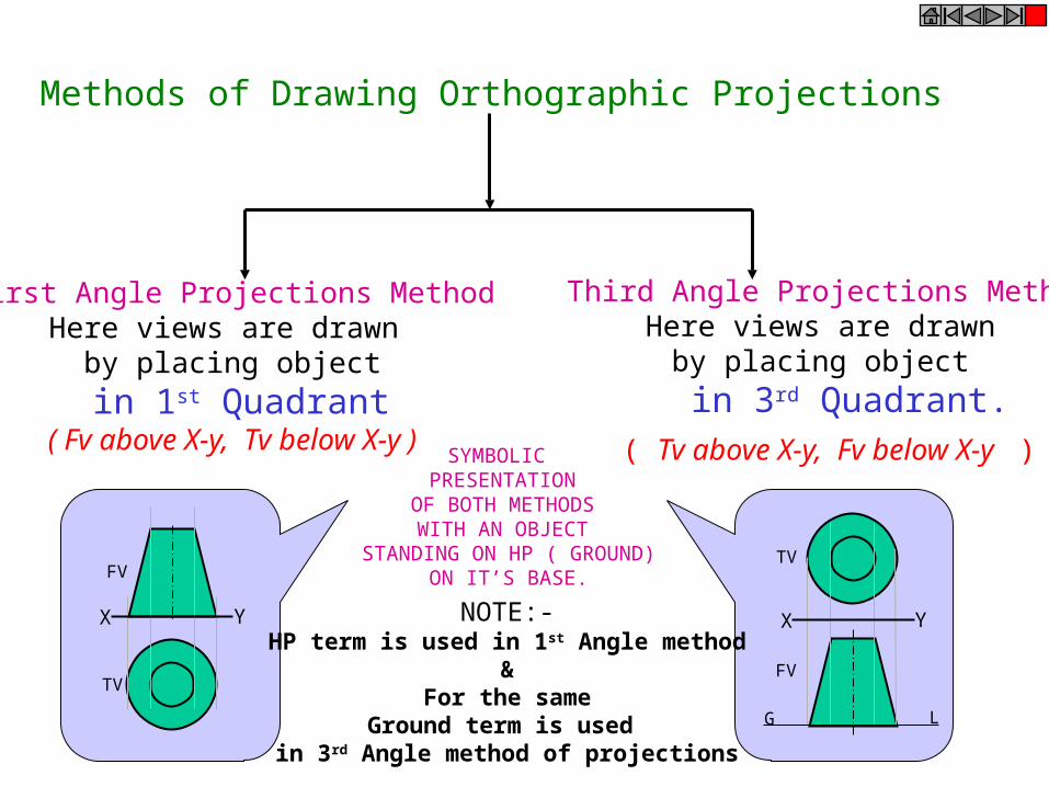
Methods of Drawing Orthographic Projections
First Angle Projections MethodHere views are drawn
by placing object
in 1st Quadrant( Fv above X-y, Tv below X-y )
Third Angle Projections MethodHere views are drawn
by placing object
in 3rd Quadrant. ( Tv above X-y, Fv below X-y )
FV
TV
X Y X Y
G L
TV
FV
SYMBOLIC PRESENTATION
OF BOTH METHODSWITH AN OBJECT
STANDING ON HP ( GROUND) ON IT’S BASE.
NOTE:-HP term is used in 1st Angle method
&For the same
Ground term is used in 3rd Angle method of projections

FOR T.V.
FOR S.V. FOR F.V.
FIRST ANGLE PROJECTION
IN THIS METHOD, THE OBJECT IS ASSUMED TO BE SITUATED IN FIRST QUADRANT
MEANS ABOVE HP & INFRONT OF VP.
OBJECT IS INBETWEENOBSERVER & PLANE.
ACTUAL PATTERN OF PLANES & VIEWS
IN FIRST ANGLE METHOD
OF PROJECTIONS
X Y
VP
HP
PP
FV LSV
TV

FOR T.V.
FOR S.V. FOR F.V.
IN THIS METHOD, THE OBJECT IS ASSUMED TO BE SITUATED IN THIRD QUADRANT( BELOW HP & BEHIND OF VP. )
PLANES BEING TRANSPERENT AND INBETWEEN
OBSERVER & OBJECT.
ACTUAL PATTERN OF PLANES & VIEWS
OF THIRD ANGLE PROJECTIONS
X Y
TV
THIRD ANGLE PROJECTION
LSV FV

Basic Line Types
Types of Lines AppearanceName according
to application
Continuous thick line Visible line
Continuous thin line Dimension line
Extension line
Leader line
Dash thick line Hidden line
Chain thin line Center line
NOTE : We will learn other types of line in later chapters.
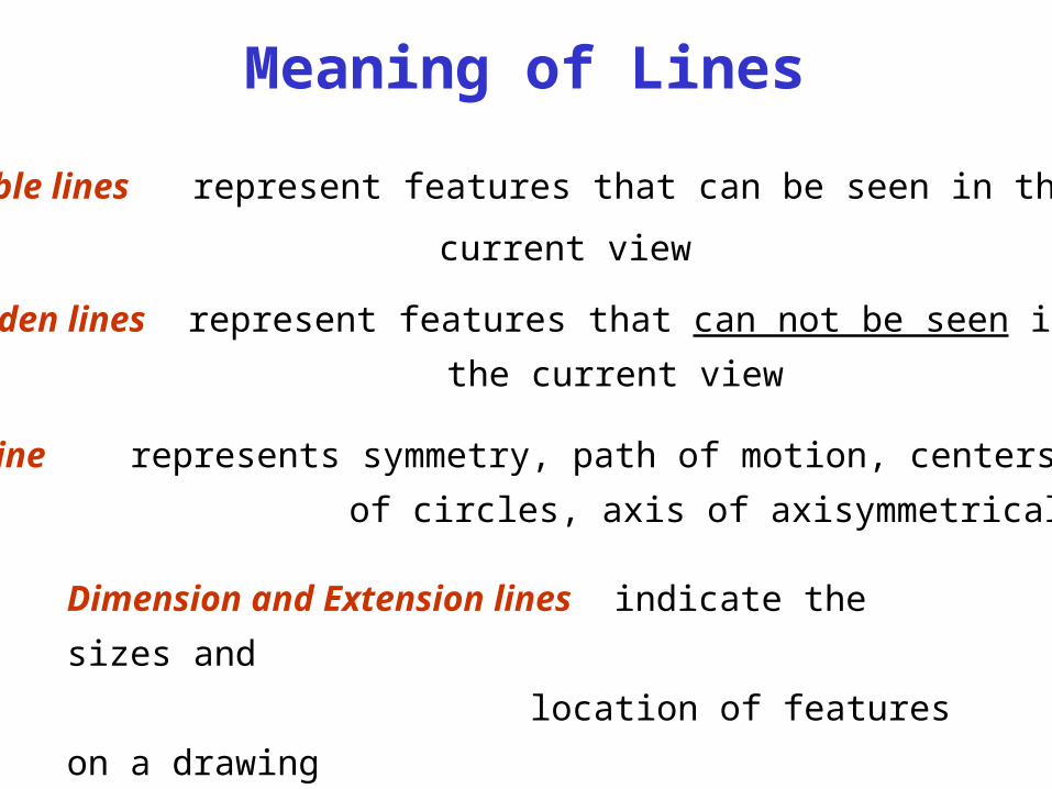
Visible lines represent features that can be seen in the
current view
Meaning of Lines
Hidden lines represent features that can not be seen in
the current view
Center line represents symmetry, path of motion, centers
of circles, axis of axisymmetrical parts
Dimension and Extension lines indicate the sizes and
location of features on a drawing

Example : Line conventions in engineering drawing