Embed Size (px)
Citation preview
Overview of ARIES ACT-1 Study
Farrokh NajmabadiProfessor of Electrical & Computer EngineeringDirector, Center for Energy ResearchUC San Diego
and the ARIES Team
Japan-US Workshop on Fusion Power Plants and Related Advanced Technologies with participations from China & KoreaFebruary 26-28, 2013
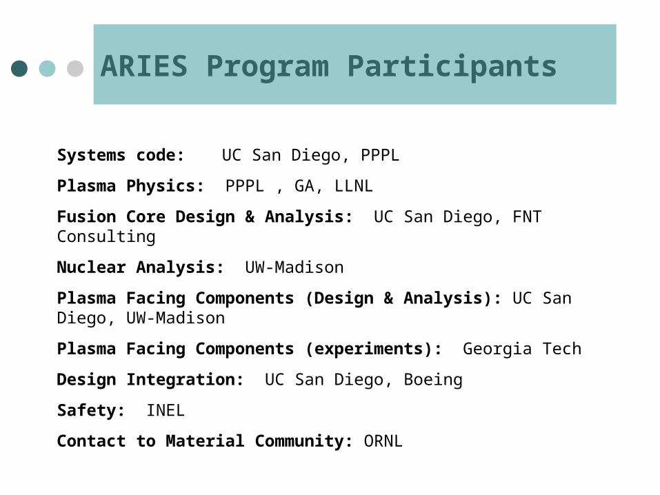
ARIES Program Participants
Systems code: UC San Diego, PPPL
Plasma Physics: PPPL , GA, LLNL
Fusion Core Design & Analysis: UC San Diego, FNT Consulting
Nuclear Analysis: UW-Madison
Plasma Facing Components (Design & Analysis): UC San Diego, UW-Madison
Plasma Facing Components (experiments): Georgia Tech
Design Integration: UC San Diego, Boeing
Safety: INEL
Contact to Material Community: ORNL
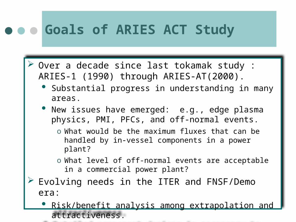
Goals of ARIES ACT Study
Over a decade since last tokamak study : ARIES-1 (1990) through ARIES-AT(2000). Substantial progress in understanding in many areas. New issues have emerged: e.g., edge plasma physics, PMI,
PFCs, and off-normal events.o What would be the maximum fluxes that can be handled by in-
vessel components in a power plant?
o What level of off-normal events are acceptable in a commercial power plant?
Evolving needs in the ITER and FNSF/Demo era: Risk/benefit analysis among extrapolation and attractiveness. Detailed component designs is necessary to understand R&D
requirements.
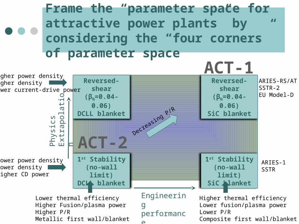
Frame the “parameter space for attractive power plants” by considering the “four corners” of parameter space
Reversed-shear(βN=0.04-0.06)DCLL blanket
Reversed-shear(βN=0.04-0.06)SiC blanket
1st Stability(no-wall limit)DCLL blanket
1st Stability(no-wall limit)SiC blanket
ARIES-RS/ATSSTR-2EU Model-D
ARIES-1SSTR
Lower thermal efficiencyHigher Fusion/plasma powerHigher P/RMetallic first wall/blanket
Higher thermal efficiencyLower fusion/plasma powerLower P/RComposite first wall/blanket
Higher power densityHigher densityLower current-drive power
Lower power densityLower densityHigher CD power
Decreasing P/R
Phy
sics
E
xtra
pola
tion
ACT-1
Engineering performance (efficiency)
ACT-2
Status of the ARIES ACT Study
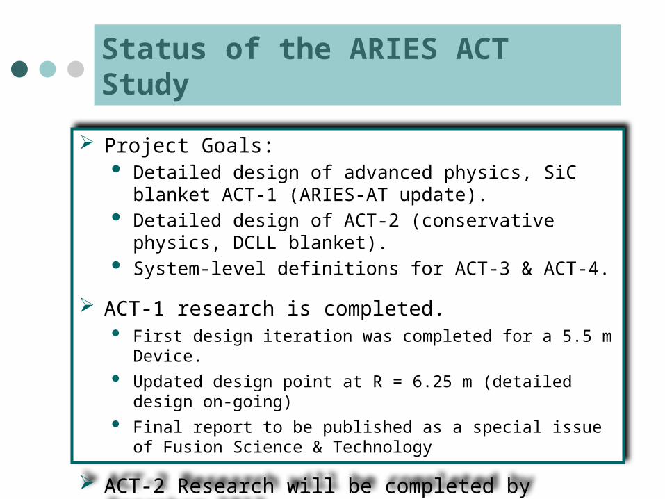
Project Goals: Detailed design of advanced physics, SiC blanket ACT-1
(ARIES-AT update). Detailed design of ACT-2 (conservative physics, DCLL
blanket). System-level definitions for ACT-3 & ACT-4.
ACT-1 research is completed. First design iteration was completed for a 5.5 m Device.
Updated design point at R = 6.25 m (detailed design on-going)
Final report to be published as a special issue of Fusion Science & Technology
ACT-2 Research will be completed by December 2013.
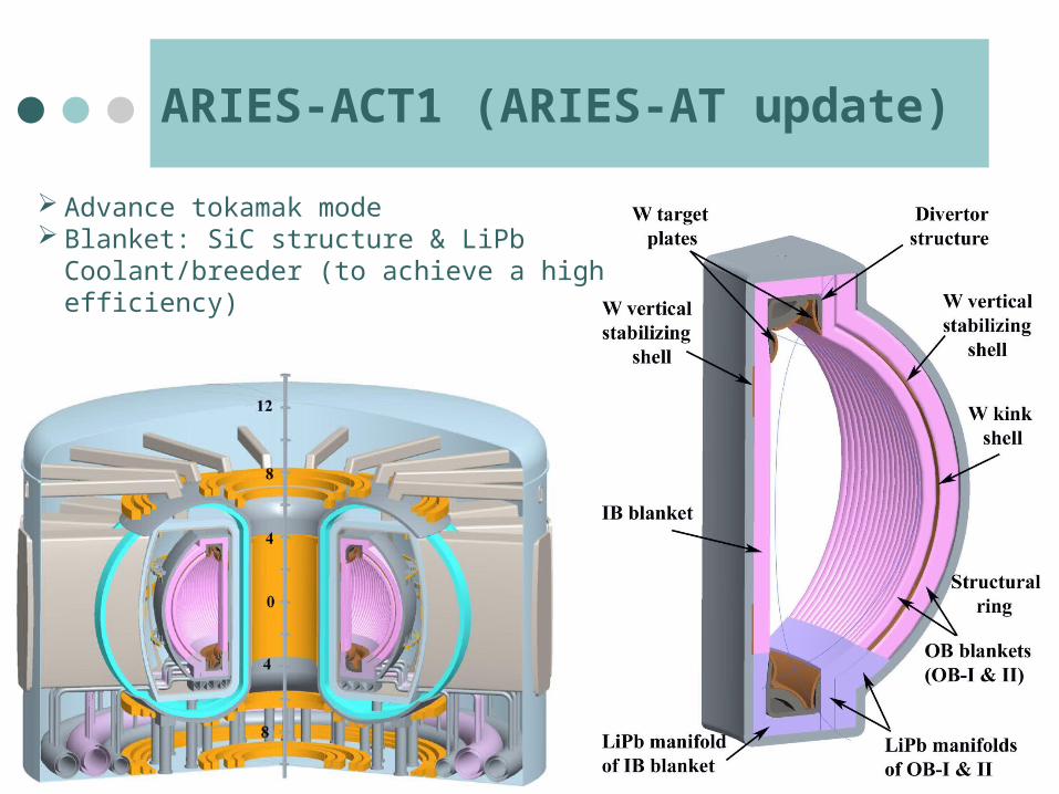
ARIES-ACT1 (ARIES-AT update)
Advance tokamak mode Blanket: SiC structure & LiPb Coolant/breeder
(to achieve a high efficiency)
ARIES Systems Code – a new approach to finding operating points
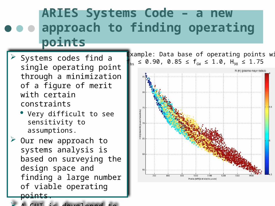
Systems codes find a single operating point through a minimization of a figure of merit with certain constraints Very difficult to see sensitivity to
assumptions. Our new approach to systems
analysis is based on surveying the design space and finding a large number of viable operating points.
A GUI is developed to visualize the data. It can impose additional constraints to explore sensitivities
Example: Data base of operating points withfbs ≤ 0.90, 0.85 ≤ fGW ≤ 1.0, H98 ≤ 1.75
Impact of the Divertor Heat load
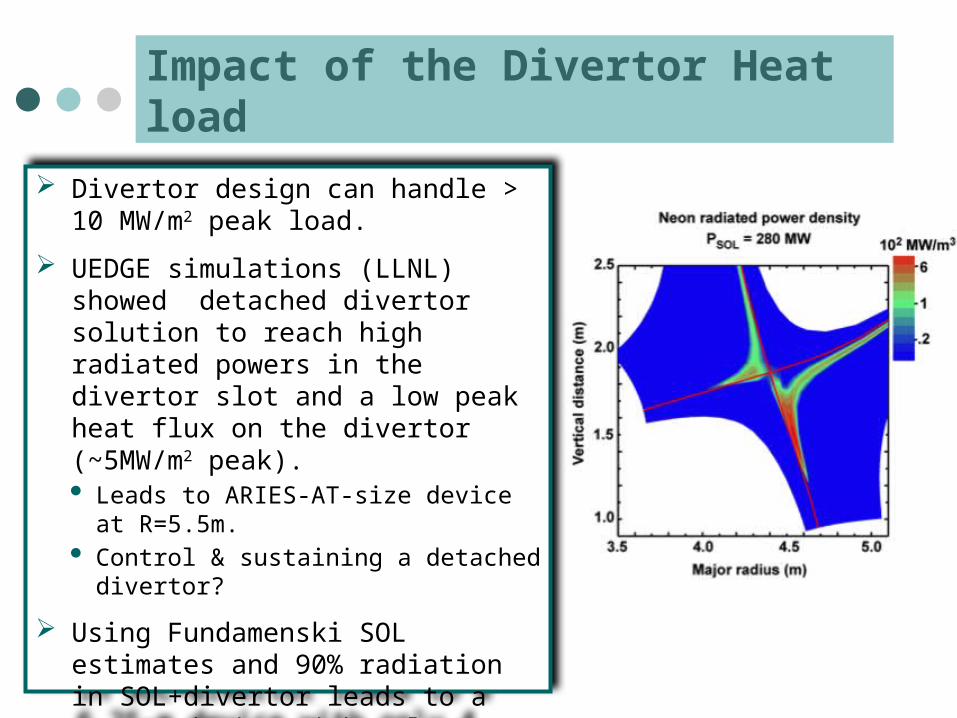
Divertor design can handle > 10 MW/m2 peak load.
UEDGE simulations (LLNL) showed detached divertor solution to reach high radiated powers in the divertor slot and a low peak heat flux on the divertor (~5MW/m2 peak). Leads to ARIES-AT-size device at
R=5.5m. Control & sustaining a detached divertor?
Using Fundamenski SOL estimates and 90% radiation in SOL+divertor leads to a 6.25-m device with only 4 mills cost penalty (current reference point). Device size is set by the divertor heat flux
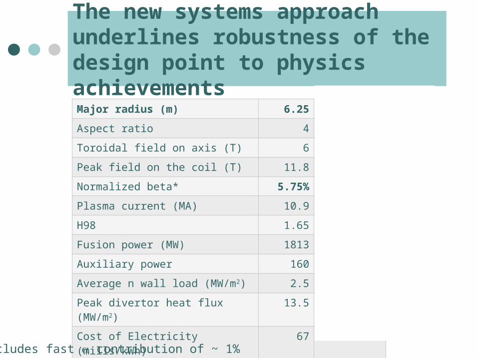
The new systems approach underlines robustness of the design point to physics achievementsMajor radius (m) 6.25 6.25
Aspect ratio 4 4
Toroidal field on axis (T) 6 7
Peak field on the coil (T) 11.8 12.9
Normalized beta* 5.75% 4.75%
Plasma current (MA) 10.9 10.9
H98 1.65 1.58
Fusion power (MW) 1813 1817
Auxiliary power 160 169
Average n wall load (MW/m2) 2.5 2.3
Peak divertor heat flux (MW/m2) 13.5 11.0
Cost of Electricity (mills/kWh) 67 68.9
* Includes fast a contribution of ~ 1%
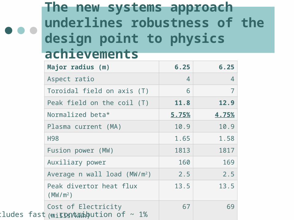
The new systems approach underlines robustness of the design point to physics achievementsMajor radius (m) 6.25 6.25
Aspect ratio 4 4
Toroidal field on axis (T) 6 7
Peak field on the coil (T) 11.8 12.9
Normalized beta* 5.75% 4.75%
Plasma current (MA) 10.9 10.9
H98 1.65 1.58
Fusion power (MW) 1813 1817
Auxiliary power 160 169
Average n wall load (MW/m2) 2.5 2.5
Peak divertor heat flux (MW/m2) 13.5 13.5
Cost of Electricity (mills/kWh) 67 69
* Includes fast a contribution of ~ 1%
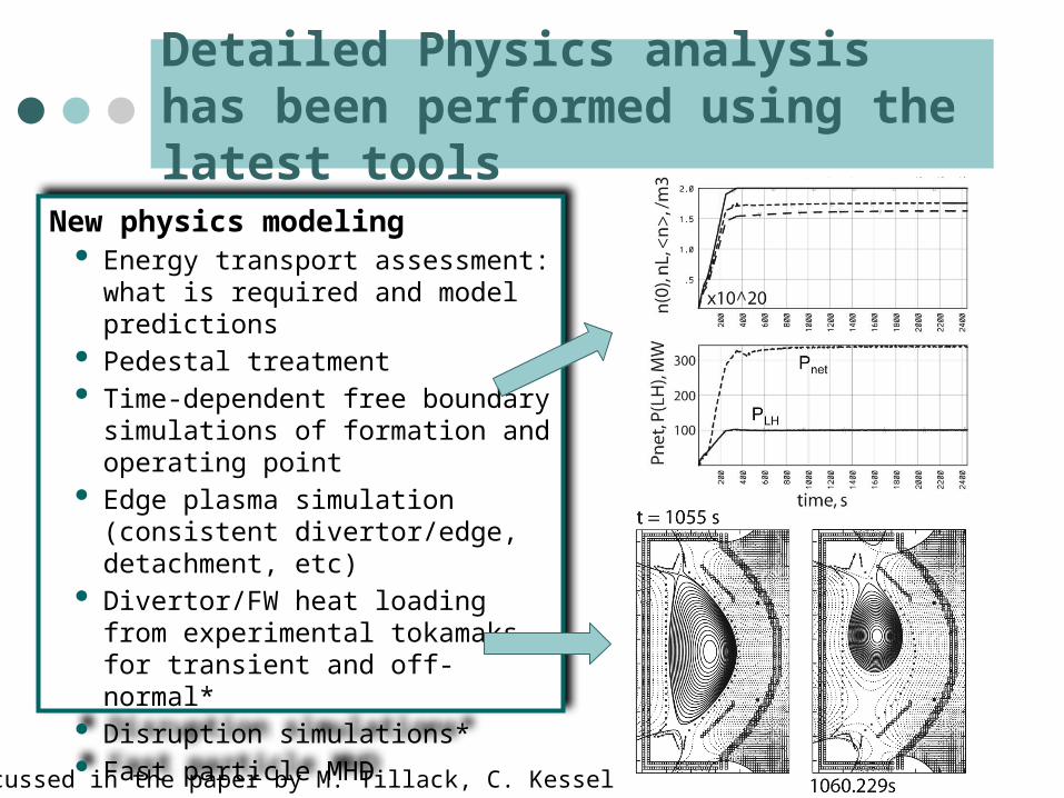
Detailed Physics analysis has been performed using the latest tools
New physics modeling Energy transport assessment: what is
required and model predictions Pedestal treatment Time-dependent free boundary
simulations of formation and operating point
Edge plasma simulation (consistent divertor/edge, detachment, etc)
Divertor/FW heat loading from experimental tokamaks for transient and off-normal*
Disruption simulations* Fast particle MHD
* Discussed in the paper by M. Tillack, C. Kessel
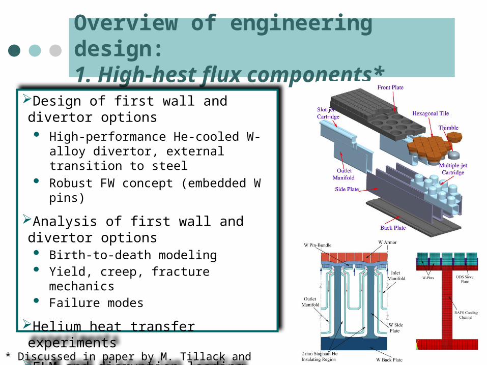
Overview of engineering design: 1. High-hest flux components*
Design of first wall and divertor options High-performance He-cooled W-alloy
divertor, external transition to steel Robust FW concept (embedded W pins)
Analysis of first wall and divertor options Birth-to-death modeling Yield, creep, fracture mechanics Failure modes
Helium heat transfer experiments
ELM and disruption loading responses Thermal, mechanical, EM &
ferromagnetic
* Discussed in paper by M. Tillack and J. Blanchard,
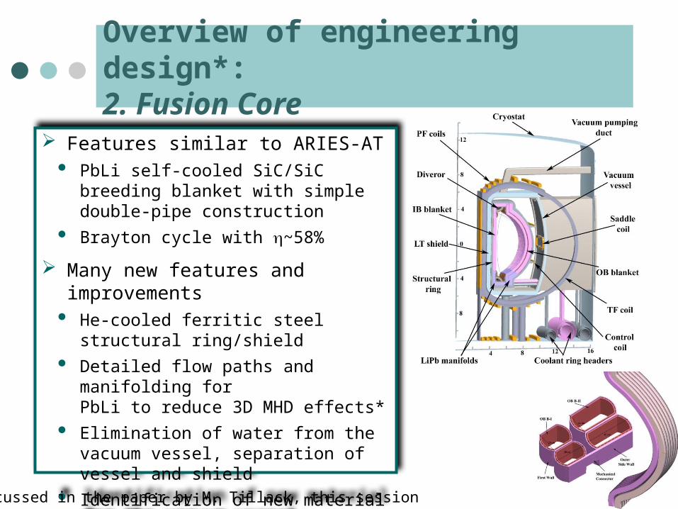
Overview of engineering design*: 2. Fusion Core
Features similar to ARIES-AT PbLi self-cooled SiC/SiC breeding
blanket with simple double-pipe construction
Brayton cycle with h~58%
Many new features and improvements He-cooled ferritic steel structural
ring/shield
Detailed flow paths and manifolding for PbLi to reduce 3D MHD effects*
Elimination of water from the vacuum vessel, separation of vessel and shield
Identification of new material for the vacuum vessel
* Discussed in the paper by M. Tillack, this session
Detailed safety analysis has highlighted impact of tritium absorption and transport
Detailed safety modeling of ARIES-AT (Petti et al) and ARIES-CS (Merrill et al, FS&T, 54, 2008 ) have shown a paradigm shift in safety issues: Use of low-activation material and care design has limited
temperature excursions and mobilization of radioactivity during accidents. Rather off-site dose is dominated by tritium.
For ARIES-CS worst-case accident, tritium release dose is 8.5 mSv (no-evacuation limit is 10 mSV)
Major implications for material and component R&D: Need to minimize tritium inventory (control of breeding,
absorption and inventory in different material)
Design implications: material choices, in-vessel components, vacuum vessel, etc.
Revisiting ARIES-AT vacuum vessel
AREIS-AT had a thick vacuum vessel (40 cm thick) with WC and water to help in shielding. (adoption of ITER vacuum vessel). Expensive and massive vacuum vessel. ITER Components are “hung” from the vacuum vessel.
ARIES sectors are self supporting (different loads).
ARIES-AT vacuum vessel operated at 50oC material? Tritium absorption? Tritium transfer to water?
Vacuum vessel temperature exceeded 100oC during an accident after a few hours (steam!)
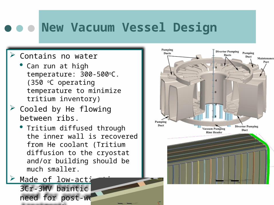
New Vacuum Vessel Design
Contains no water Can run at high temperature: 300-
500oC. (350 oC operating temperature to minimize tritium inventory)
Cooled by He flowing between ribs. Tritium diffused through the inner
wall is recovered from He coolant (Tritium diffusion to the cryostat and/or building should be much smaller.
Made of low-activation 3Cr-3WV baintic steel (no need for post-weld heat treatment).
In summary …
ARIES-ACT study is re-examining the tokamak power plant space to understand risk and trade-offs of higher physics and engineering performance with special emphais on PMI/PFC and off-normal events. ARIES-ACT1 (updated ARIES-AT) is near completion. Detailed physics analysis with modern computational tools are
used. Many new physics issues are included. The new system approach indicate a robust design window for this
class of power plants. Many engineering imporvements: He-cooled ferritic steel structural
ring/shield, Detailed flow paths and manifolding to reduce 3D MHD effects, Identification of new material for the vacuum vessel …
In-elastic analysis of component including Birth-to-death modeling and fracture mechanics indicate a higher performance PFCs are possible. Many issues/properties for material development & optimization are identified.
Thank you!