Embed Size (px)
Citation preview
EERA Technical Report – CAES, X Luo and J Wang
OVERVIEW OF CURRENT DEVELOPMENT ON
COMPRESSED AIR ENERGY STORAGE
TECHNICAL REPORT
XING LUO, JIHONG WANG
© DECEMBER, 2013
SCHOOL OF ENGINEERING
UNIVERSITY OF WARWICK, COVENTRY CV4 7AL, UK
EERA Technical Report – CAES, X Luo and J Wang 1
CONTENTS
1 Introduction
2 Working Principles of Compressed Air Energy Storage (CAES)
3 Introduction of Commercialized CAES Facilities
4 Current Research and Development of CAES
5 Overview of the Geological Study of Underground Cavern for
CAES
6 Description of CAES Technological Characteristics
7 Economic Analysis Brief
8 Application Potentials
9 Challenges and Emergent Needs on Development of CAES
10 Concluding Remarks
EERA Technical Report – CAES, X Luo and J Wang 2
1 INTRODUCTION
Electrical Energy Storage (EES) refers to a technological process, in which electrical energy
is converted into different forms of energy suitable for storage and the energy stored can then
be converted into electrical energy when needed. The history of EES technology can be dated
back to the 19th century. The first rechargeable lead–acid battery was invented in 1859 and
the first utility scale pumped hydro storage was installed in the 1890s [1-3]. EES with suitable
scales has long been considered as crucial mechanism for ensuring power system operation
stability and reliability; in particular, it has recently attracted more attentions due to the
rapidly increased renewable power generation. It is well recognized that EES can bring
numerous benefits to energy system operation and management. Among all the EES
technologies, Pumped Hydroelectric Storage (PHS) is a well-known mature large-scale EES
technology and is in commercial operation. Compressed Air Energy Storage (CAES) is
another commercialized EES technology in large scale which can provide above 100 MW
power output via a single unit.
CAES operates in the way of storing energy in the form of high pressure compressed air
during the periods of low electric energy demand and then releasing the stored compressed air
energy to generate electricity to meet high demand during the peak time periods. CAES can
be built to have the scales from small to large and the storage durations from short to long
with moderate response time and good part-load performance. Any one CAES installation
refers to the establishment of a system with integration of different interacting components,
devices and processes, such as compressors, turbines/expanders and electrical machines.
CAES is often hybrid or combining with alternative energy storage technologies to achieve
the required energy capacity, energy density, response time or efficiency. For instance, the
combination of CAES with supercapacitor will improve its transition response performance;
combining with thermal energy storage will reuse the heat generated from compression
process which will improve the round-trip efficiency.
Successful CAES implementation derives from the mid of the 20th century. In 1949, S. Laval
obtained the patent on using air to store power inside an underground air-storage cavern,
which marked the new era of CAES applications [4]. The world’s first utility-scale CAES
plant was installed and commissioned to operation by Brown Boveri (today “Asea Brown
Boveri (ABB)”) at Huntorf, Germany, in 1978 [4]. It has the rated power generation of 290
MW, for providing load following service and meeting the peak demand while maintaining
constant capacity factor in the nuclear power industry [4, 5]. As an available approach for
peak load shifting in power grid operation and due to its relatively low cost compared to oil
and gas prices through the 1980s to 1990s, the CAES technology development and its
EERA Technical Report – CAES, X Luo and J Wang 3
industrial applications continued staying attractive. In 1991, another large-scale CAES plant
commenced operation in McIntosh, Alabama, US [5]. The 110 MW plant, with a storage
capacity of 2,700 MWh, is capable of continuously delivering its full power output for up to
26 hours; the plant is used to store off-peak power, generate peak power and provide spinning
reserves [5, 6]. Recently, the interests to small-scale CAES and related hybrid systems are
growing and technologies in this area are rapidly developing. It is expected to use CAES as an
alternative to chemical batteries in many application areas, such as Uninterruptible Power
Supplies (UPS), stand-alone and back-up power systems. For example, in 2009, Energetix
Group launched its small-scale compressed air UPS products to the market [7]. Also, Liquid
Air Energy Storage (LAES) can be considered as a variant of CAES since many important
components needed in building a LAES system are also required by CAES, such as
compressors, turbines/expanders, electric motors/generators and sometimes heat exchangers.
The UK based Highview Power Storage implemented a pilot LAES facility (300 kW, 2.5
MWh storage capacity) that has been in operation at an 80 MW biomass plant since 2010 [8].
This report will introduce the working principles of CAES, current technology development,
typical technical characteristics, existing facilities, application potentials , technological and
economic challenges, and issues associated with future development of CAES.
2 WORKING PRINCIPLES OF CAES
The conventional CAES may be rooted from gas turbine technologies. The main feature of
the conventional CAES is: it involves combusting fossil fuels via gas turbines and resulting in
CO2 emissions. In the conventional CAES system, the main shaft is used to connect all
primary components including the compressors, a reversible electric machine and the turbines
with clutches. Both the Huntorf and the McIntosh plants were implemented through the
conventional CAES technology.
The working process of a conventional large-scale CAES plant can be considered to have the
similarities to that of a gas turbine based power plant except that the process of CAES
decouples the compression and expansion cycles of a gas turbine into two separate processes
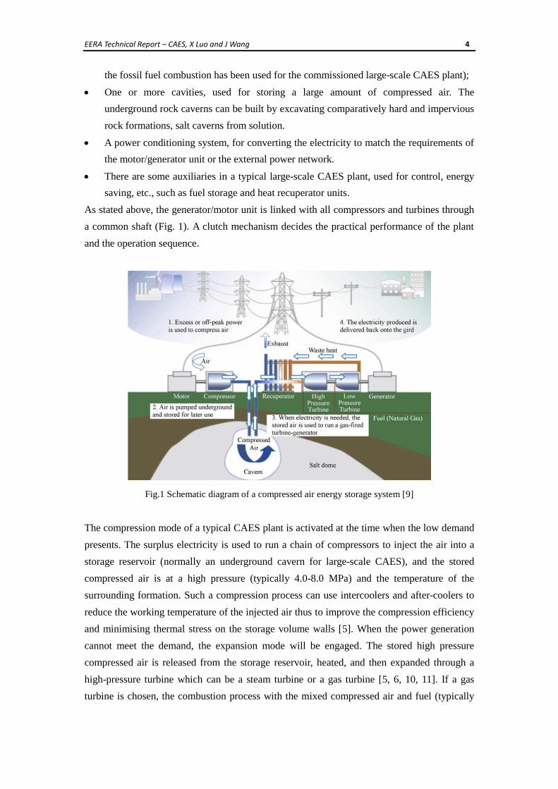
occurring at different time. Fig. 1 shows a schematic diagram for a typical large-scale CAES
plant which is composed of six major sections:
A motor/generator unit combined with clutch mechanisms to provide alternate
engagement to the compression or the expansion mode.
A multi-stage compressor unit operating with intercoolers and after-coolers, which can
provide economic air compression operating process.
A turbine train, containing both high-pressure and low-pressure turbines (the turbine with
EERA Technical Report – CAES, X Luo and J Wang 4
the fossil fuel combustion has been used for the commissioned large-scale CAES plant);
One or more cavities, used for storing a large amount of compressed air. The
underground rock caverns can be built by excavating comparatively hard and impervious
rock formations, salt caverns from solution.
A power conditioning system, for converting the electricity to match the requirements of
the motor/generator unit or the external power network.
There are some auxiliaries in a typical large-scale CAES plant, used for control, energy
saving, etc., such as fuel storage and heat recuperator units.
As stated above, the generator/motor unit is linked with all compressors and turbines through
a common shaft (Fig. 1). A clutch mechanism decides the practical performance of the plant
and the operation sequence.
Fig.1 Schematic diagram of a compressed air energy storage system [9]
The compression mode of a typical CAES plant is activated at the time when the low demand
presents. The surplus electricity is used to run a chain of compressors to inject the air into a
storage reservoir (normally an underground cavern for large-scale CAES), and the stored
compressed air is at a high pressure (typically 4.0-8.0 MPa) and the temperature of the
surrounding formation. Such a compression process can use intercoolers and after-coolers to
reduce the working temperature of the injected air thus to improve the compression efficiency
and minimising thermal stress on the storage volume walls [5]. When the power generation
cannot meet the demand, the expansion mode will be engaged. The stored high pressure
compressed air is released from the storage reservoir, heated, and then expanded through a
high-pressure turbine which can be a steam turbine or a gas turbine [5, 6, 10, 11]. If a gas
turbine is chosen, the combustion process with the mixed compressed air and fuel (typically
EERA Technical Report – CAES, X Luo and J Wang 5
natural gas) occurs in the combustor of the high-pressure turbine. Then the gas from the outlet
of high-pressure turbine mixed with additional fuel is combusted in the combustor of the
low-pressure gas turbine. Both the high-pressure and low-pressure turbines are connected to
an electrical generator to generate electricity (Fig. 1). The waste heat of the overall system
exhaust can be recycled before released to atmosphere; for instance, a heat recuperator unit
has been used to recover heat energy from the exhaust gas at McIntosh CAES plant. Also, it is
worth noting that the airflow from the reservoir to the turbine must be high enough to meet
the system operation requirements. The low temperature obtained from the incomplete or the
absence of combustion in the expansion mode would pose a significant risk for turbine blades
[5].
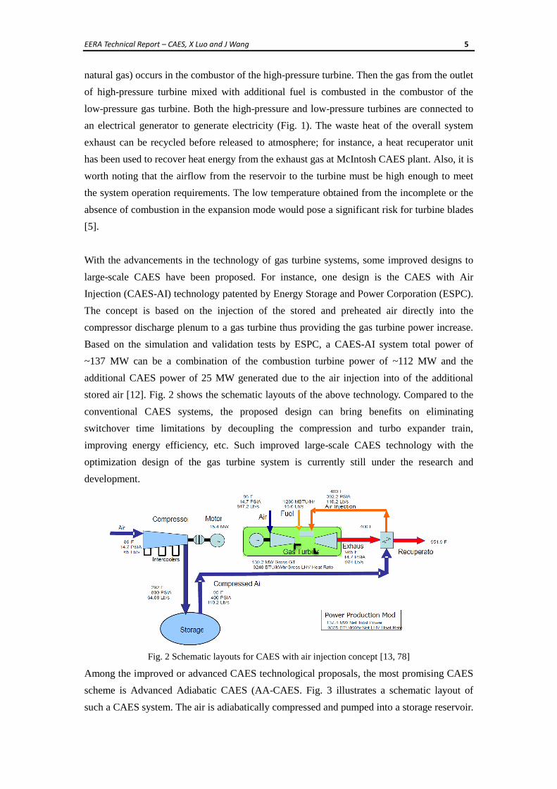
With the advancements in the technology of gas turbine systems, some improved designs to
large-scale CAES have been proposed. For instance, one design is the CAES with Air
Injection (CAES-AI) technology patented by Energy Storage and Power Corporation (ESPC).
The concept is based on the injection of the stored and preheated air directly into the
compressor discharge plenum to a gas turbine thus providing the gas turbine power increase.
Based on the simulation and validation tests by ESPC, a CAES-AI system total power of
~137 MW can be a combination of the combustion turbine power of ~112 MW and the
additional CAES power of 25 MW generated due to the air injection into of the additional
stored air [12]. Fig. 2 shows the schematic layouts of the above technology. Compared to the
conventional CAES systems, the proposed design can bring benefits on eliminating
switchover time limitations by decoupling the compression and turbo expander train,
improving energy efficiency, etc. Such improved large-scale CAES technology with the
optimization design of the gas turbine system is currently still under the research and
development.
Fig. 2 Schematic layouts for CAES with air injection concept [13, 78]
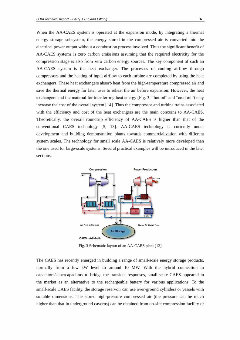
Among the improved or advanced CAES technological proposals, the most promising CAES
scheme is Advanced Adiabatic CAES (AA-CAES. Fig. 3 illustrates a schematic layout of
such a CAES system. The air is adiabatically compressed and pumped into a storage reservoir.
EERA Technical Report – CAES, X Luo and J Wang 6
When the AA-CAES system is operated at the expansion mode, by integrating a thermal
energy storage subsystem, the energy stored in the compressed air is converted into the
electrical power output without a combustion process involved. Thus the significant benefit of
AA-CAES systems is zero carbon emissions assuming that the required electricity for the
compression stage is also from zero carbon energy sources. The key component of such an
AA-CAES system is the heat exchanger. The processes of cooling airflow through
compressors and the heating of input airflow to each turbine are completed by using the heat
exchangers. These heat exchangers absorb heat from the high-temperature compressed air and
save the thermal energy for later uses to reheat the air before expansion. However, the heat
exchangers and the material for transferring heat energy (Fig. 3, “hot oil” and “cold oil”) may
increase the cost of the overall system [14]. Thus the compressor and turbine trains associated
with the efficiency and cost of the heat exchangers are the main concerns to AA-CAES.
Theoretically, the overall roundtrip efficiency of AA-CAES is higher than that of the
conventional CAES technology [5, 13]. AA-CAES technology is currently under
development and building demonstration plants towards commercialization with different
system scales. The technology for small scale AA-CAES is relatively more developed than
the one used for large-scale systems. Several practical examples will be introduced in the later
sections.
Fig. 3 Schematic layout of an AA-CAES plant [13]
The CAES has recently emerged in building a range of small-scale energy storage products,
normally from a few kW level to around 10 MW. With the hybrid connection to
capacitors/supercapacitors to bridge the transient responses, small-scale CAES appeared in
the market as an alternative to the rechargeable battery for various applications. To the
small-scale CAES facility, the storage reservoir can use over-ground cylinders or vessels with
suitable dimensions. The stored high-pressure compressed air (the pressure can be much
higher than that in underground caverns) can be obtained from on-site compression facility or
EERA Technical Report – CAES, X Luo and J Wang 7
delivered to the site in the form of pre-filled high-pressure air cylinders through the
compressed air product supply chain. The air turbine/expander used to drive an electrical
generator is the key component in such small-scale CAES facilities which require high
efficiency, fast response and low/free maintenance.
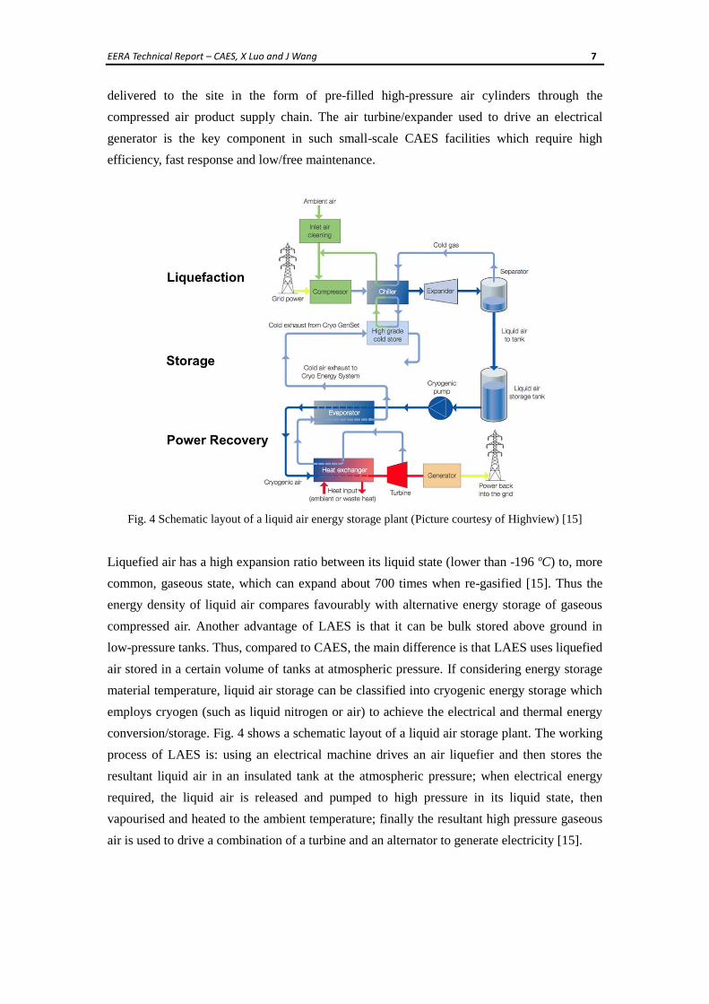
Fig. 4 Schematic layout of a liquid air energy storage plant (Picture courtesy of Highview) [15]
Liquefied air has a high expansion ratio between its liquid state (lower than -196 ºC) to, more
common, gaseous state, which can expand about 700 times when re-gasified [15]. Thus the
energy density of liquid air compares favourably with alternative energy storage of gaseous
compressed air. Another advantage of LAES is that it can be bulk stored above ground in
low-pressure tanks. Thus, compared to CAES, the main difference is that LAES uses liquefied
air stored in a certain volume of tanks at atmospheric pressure. If considering energy storage
material temperature, liquid air storage can be classified into cryogenic energy storage which
employs cryogen (such as liquid nitrogen or air) to achieve the electrical and thermal energy
conversion/storage. Fig. 4 shows a schematic layout of a liquid air storage plant. The working
process of LAES is: using an electrical machine drives an air liquefier and then stores the
resultant liquid air in an insulated tank at the atmospheric pressure; when electrical energy
required, the liquid air is released and pumped to high pressure in its liquid state, then
vapourised and heated to the ambient temperature; finally the resultant high pressure gaseous
air is used to drive a combination of a turbine and an alternator to generate electricity [15].
EERA Technical Report – CAES, X Luo and J Wang 8
3 INTRODUCTION OF COMMERCIALIZED CAES FACILITIES
3.1 THE HUNTORF CAES PLANT
The Huntorf CAES plant, the first commercialized large-scale CAES facility in the world,
was built in Germany in 1978 [11]. The plant was designed to provide black-start power to
nuclear units located near to the North Sea and also served to level and reduce the prices of
the peak power demand. After the Huntorf CAES plant started operation, its mandate was
updated to include the support of other facilities, such as back-up for the local power system,
filling the energy gap due to the slow response of coal fired power plants, buffering against
the intermittence of wind energy production in Northern Germany [5].
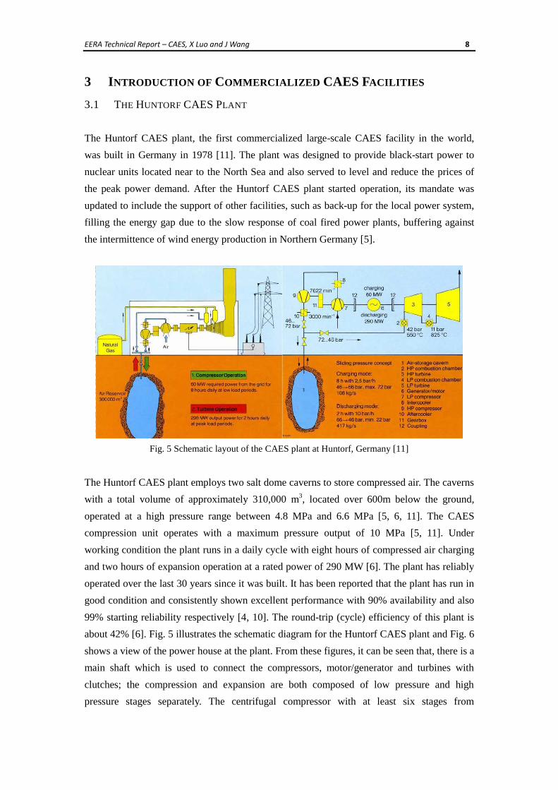
Fig. 5 Schematic layout of the CAES plant at Huntorf, Germany [11]
The Huntorf CAES plant employs two salt dome caverns to store compressed air. The caverns
with a total volume of approximately 310,000 m3, located over 600m below the ground,
operated at a high pressure range between 4.8 MPa and 6.6 MPa [5, 6, 11]. The CAES
compression unit operates with a maximum pressure output of 10 MPa [5, 11]. Under
working condition the plant runs in a daily cycle with eight hours of compressed air charging
and two hours of expansion operation at a rated power of 290 MW [6]. The plant has reliably
operated over the last 30 years since it was built. It has been reported that the plant has run in
good condition and consistently shown excellent performance with 90% availability and also
99% starting reliability respectively [4, 10]. The round-trip (cycle) efficiency of this plant is
about 42% [6]. Fig. 5 illustrates the schematic diagram for the Huntorf CAES plant and Fig. 6
shows a view of the power house at the plant. From these figures, it can be seen that, there is a
main shaft which is used to connect the compressors, motor/generator and turbines with
clutches; the compression and expansion are both composed of low pressure and high
pressure stages separately. The centrifugal compressor with at least six stages from

EERA Technical Report – CAES, X Luo and J Wang 9
low-pressure to high-pressure is used at Huntorf. The compression module is capable of
drawing 108 kg/s, while the expansion module is capable of processing 417 kg/s of air [5, 6,
11].
Fig. 6 A view of the power house at the Huntorf CAES plant [17]
3.2 THE MCINTOSH CAES PLANT
Another commercialized large-scale CAES facility started operation in McIntosh, Alabama,
U.S. in 1991 [6]. The project was implemented by Dresser-Rand, and the CAES plant was
built by Alabama Electric Cooperative [5]. A schematic diagram to illustrate the structural
layout of the McIntosh plant is shown in Fig. 7.
Fig. 7 Schematic layout of CAES plant at McIntosh, Alabama, U.S. [12]
The 110 MW McIntosh CAES plant was designed to be operated for up to 26 hours
continuously at its full power. The storage capacity of plant is about 560,000 m3, utilising a
single salt dome cavern, about 450 m under the ground, to store the compressed air in the
range of 4.5 MPa to 7.4 MPa [5, 6, 10]. From Fig. 7, it can be seen that the structure of
McIntosh CAES plant is similar to that of the Huntorf CAES plant. The major improvement
EERA Technical Report – CAES, X Luo and J Wang 10
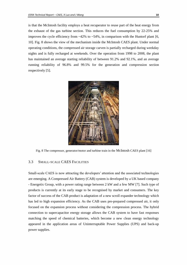
is that the McIntosh facility employs a heat recuperator to reuse part of the heat energy from
the exhaust of the gas turbine section. This reduces the fuel consumption by 22-25% and
improves the cycle efficiency from ~42% to ~54%, in comparison with the Huntorf plant [6,
10]. Fig. 8 shows the view of the mechanism inside the McIntosh CAES plant. Under normal
operating conditions, the compressed air storage carven is partially recharged during weekday
nights and is fully recharged at weekends. Over the operation from 1998 to 2008, the plant
has maintained an average starting reliability of between 91.2% and 92.1%, and an average
running reliability of 96.8% and 99.5% for the generation and compression section
respectively [5].
Fig. 8 The compressor, generator/motor and turbine train in the McIntosh CAES plant [16]
3.3 SMALL-SCALE CAES FACILITIES
Small-scale CAES is now attracting the developers’ attention and the associated technologies
are emerging. A Compressed Air Battery (CAB) system is developed by a UK based company
- Energetix Group, with a power rating range between 2 kW and a few MW [7]. Such type of
products is currently at its early stage to be recognised by market and consumers. The key
factor of success of the CAB product is adaptation of a new scroll expander technology which
has led to high expansion efficiency. As the CAB uses pre-prepared compressed air, it only
focused on the expansion process without considering the compression process. The hybrid
connection to supercapacitor energy storage allows the CAB system to have fast responses
matching the speed of chemical batteries, which become a new clean energy technology
appeared in the application areas of Uninterruptable Power Supplies (UPS) and back-up
power supplies.
EERA Technical Report – CAES, X Luo and J Wang 11
The scroll technology has been mainly used in compressors for air conditioners and
refrigerators [19, 20]. Recently, the scroll compressor technology has been reinvented to build
scroll expanders, that is, expending the air instead of compressing it. The recent research has
provided the evidence to explain why the scroll expander has relatively higher energy
conversion efficiency compared with its traditional pneumatic counterparts [20-22].
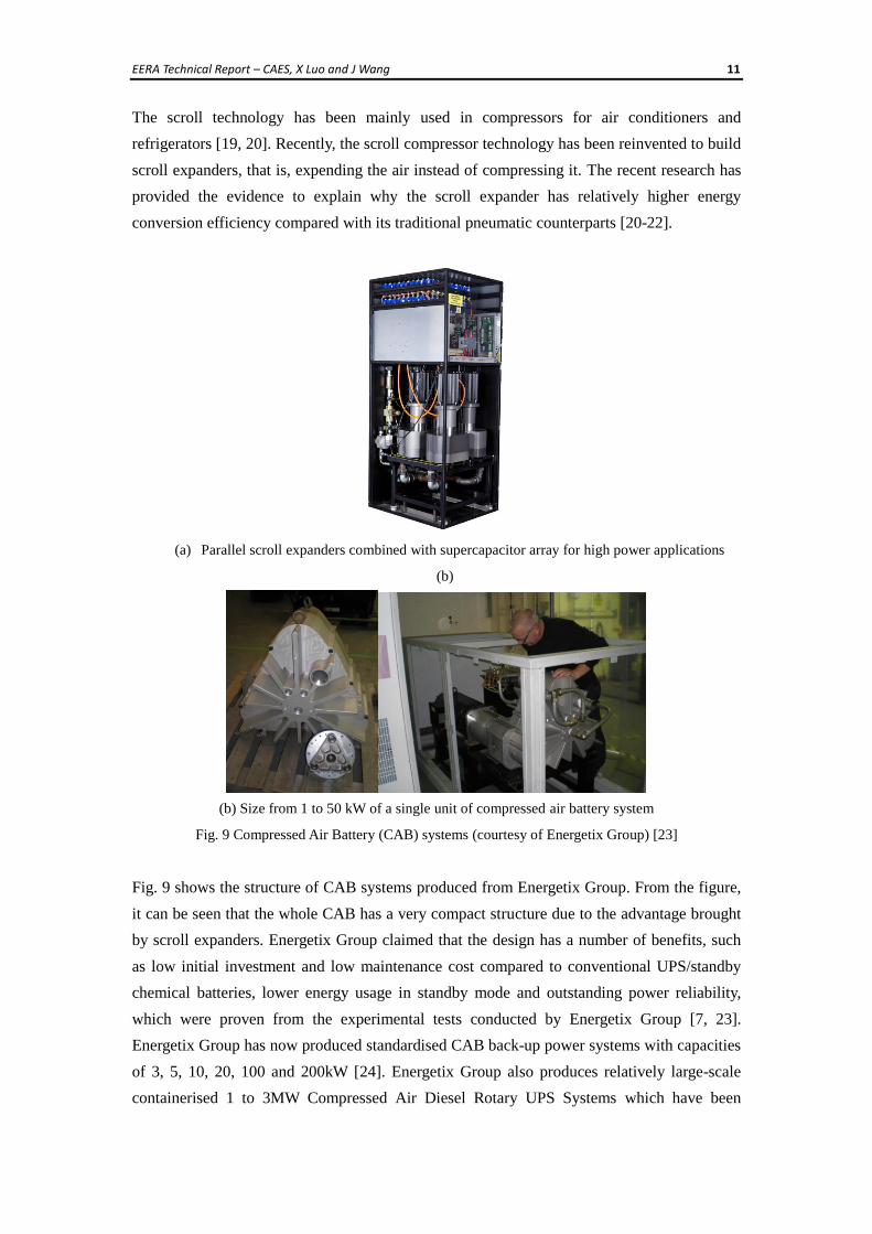
(a) Parallel scroll expanders combined with supercapacitor array for high power applications
(b)
(b) Size from 1 to 50 kW of a single unit of compressed air battery system
Fig. 9 Compressed Air Battery (CAB) systems (courtesy of Energetix Group) [23]
Fig. 9 shows the structure of CAB systems produced from Energetix Group. From the figure,
it can be seen that the whole CAB has a very compact structure due to the advantage brought
by scroll expanders. Energetix Group claimed that the design has a number of benefits, such
as low initial investment and low maintenance cost compared to conventional UPS/standby
chemical batteries, lower energy usage in standby mode and outstanding power reliability,
which were proven from the experimental tests conducted by Energetix Group [7, 23].
Energetix Group has now produced standardised CAB back-up power systems with capacities
of 3, 5, 10, 20, 100 and 200kW [24]. Energetix Group also produces relatively large-scale
containerised 1 to 3MW Compressed Air Diesel Rotary UPS Systems which have been
EERA Technical Report – CAES, X Luo and J Wang 12
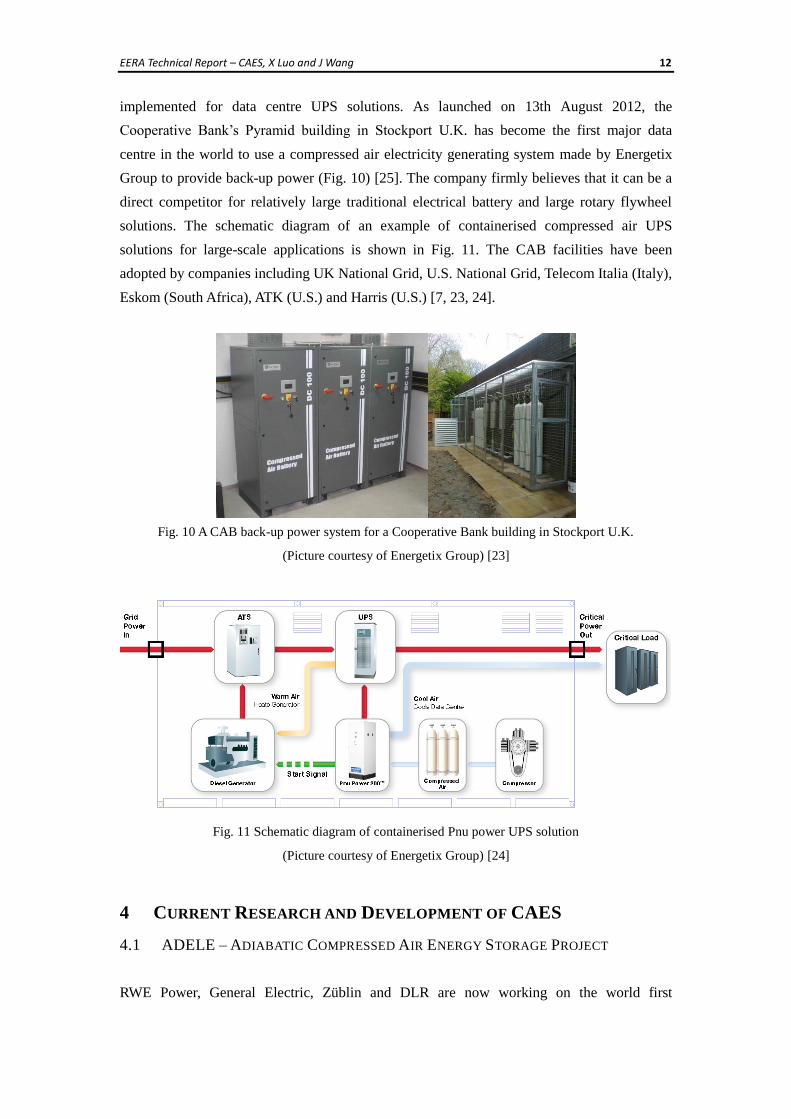
implemented for data centre UPS solutions. As launched on 13th August 2012, the
Cooperative Bank’s Pyramid building in Stockport U.K. has become the first major data
centre in the world to use a compressed air electricity generating system made by Energetix
Group to provide back-up power (Fig. 10) [25]. The company firmly believes that it can be a
direct competitor for relatively large traditional electrical battery and large rotary flywheel
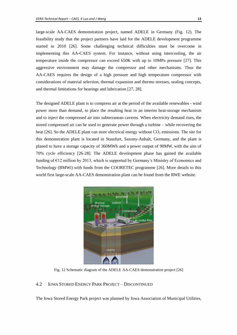
solutions. The schematic diagram of an example of containerised compressed air UPS
solutions for large-scale applications is shown in Fig. 11. The CAB facilities have been
adopted by companies including UK National Grid, U.S. National Grid, Telecom Italia (Italy),
Eskom (South Africa), ATK (U.S.) and Harris (U.S.) [7, 23, 24].
Fig. 10 A CAB back-up power system for a Cooperative Bank building in Stockport U.K.
(Picture courtesy of Energetix Group) [23]
Fig. 11 Schematic diagram of containerised Pnu power UPS solution
(Picture courtesy of Energetix Group) [24]
4 CURRENT RESEARCH AND DEVELOPMENT OF CAES
4.1 ADELE – ADIABATIC COMPRESSED AIR ENERGY STORAGE PROJECT
RWE Power, General Electric, Züblin and DLR are now working on the world first
EERA Technical Report – CAES, X Luo and J Wang 13
large-scale AA-CAES demonstration project, named ADELE in Germany (Fig. 12). The
feasibility study that the project partners have laid for the ADELE development programme
started in 2010 [26]. Some challenging technical difficulties must be overcome in
implementing this AA-CAES system. For instance, without using intercooling, the air
temperature inside the compressor can exceed 650K with up to 10MPa pressure [27]. This
aggressive environment may damage the compressor and other mechanisms. Thus the
AA-CAES requires the design of a high pressure and high temperature compressor with
considerations of material selection, thermal expansion and thermo stresses, sealing concepts,
and thermal limitations for bearings and lubrication [27, 28].
The designed ADELE plant is to compress air at the period of the available renewables - wind
power more than demand, to place the resulting heat in an interim heat-storage mechanism
and to inject the compressed air into subterranean caverns. When electricity demand rises, the
stored compressed air can be used to generate power through a turbine – while recovering the
heat [26]. So the ADELE plant can store electrical energy without CO2 emissions. The site for
this demonstration plant is located in Stassfurt, Saxony-Anhalt, Germany, and the plant is
planed to have a storage capacity of 360MWh and a power output of 90MW, with the aim of
70% cycle efficiency [26-28]. The ADELE development phase has gained the available
funding of €12 million by 2013, which is supported by Germany’s Ministry of Economics and
Technology (BMWi) with funds from the COORETEC programme [26]. More details to this
world first large-scale AA-CAES demonstration plant can be found from the RWE website.
Fig. 12 Schematic diagram of the ADELE AA-CAES demonstration project [26]
4.2 IOWA STORED ENERGY PARK PROJECT – DISCONTINUED
The Iowa Stored Energy Park project was planned by Iowa Association of Municipal Utilities,
EERA Technical Report – CAES, X Luo and J Wang 14
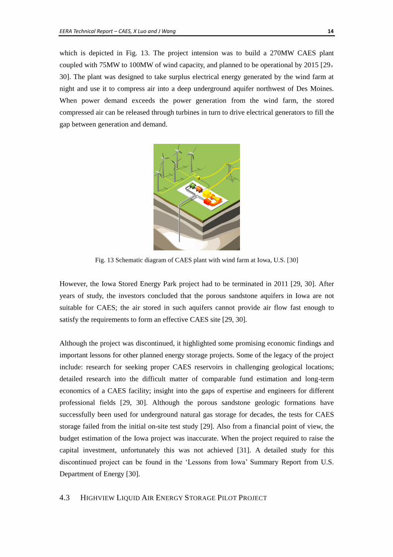
which is depicted in Fig. 13. The project intension was to build a 270MW CAES plant
coupled with 75MW to 100MW of wind capacity, and planned to be operational by 2015 [29,
30]. The plant was designed to take surplus electrical energy generated by the wind farm at
night and use it to compress air into a deep underground aquifer northwest of Des Moines.
When power demand exceeds the power generation from the wind farm, the stored
compressed air can be released through turbines in turn to drive electrical generators to fill the
gap between generation and demand.
Fig. 13 Schematic diagram of CAES plant with wind farm at Iowa, U.S. [30]
However, the Iowa Stored Energy Park project had to be terminated in 2011 [29, 30]. After
years of study, the investors concluded that the porous sandstone aquifers in Iowa are not
suitable for CAES; the air stored in such aquifers cannot provide air flow fast enough to
satisfy the requirements to form an effective CAES site [29, 30].
Although the project was discontinued, it highlighted some promising economic findings and
important lessons for other planned energy storage projects. Some of the legacy of the project
include: research for seeking proper CAES reservoirs in challenging geological locations;
detailed research into the difficult matter of comparable fund estimation and long-term
economics of a CAES facility; insight into the gaps of expertise and engineers for different
professional fields [29, 30]. Although the porous sandstone geologic formations have
successfully been used for underground natural gas storage for decades, the tests for CAES
storage failed from the initial on-site test study [29]. Also from a financial point of view, the
budget estimation of the Iowa project was inaccurate. When the project required to raise the
capital investment, unfortunately this was not achieved [31]. A detailed study for this
discontinued project can be found in the ‘Lessons from Iowa’ Summary Report from U.S.
Department of Energy [30].
4.3 HIGHVIEW LIQUID AIR ENERGY STORAGE PILOT PROJECT
EERA Technical Report – CAES, X Luo and J Wang 15
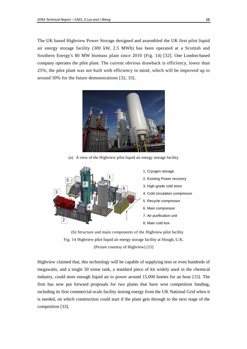
The UK based Highview Power Storage designed and assembled the UK first pilot liquid
air energy storage facility (300 kW, 2.5 MWh) has been operated at a Scottish and
Southern Energy's 80 MW biomass plant since 2010 (Fig. 14) [32]. One London-based
company operates the pilot plant. The current obvious drawback is efficiency, lower than
25%; the pilot plant was not built with efficiency in mind, which will be improved up to
around 50% for the future demonstrations [32, 33].
(a) A view of the Highview pilot liquid air energy storage facility
1. Cryogen storage
2. Existing Power recovery
3. High grade cold store
4. Cold circulation compressor
5. Recycle compressor
6. Main compressor
7. Air purification unit
8. Main cold box
1
2
3
4
5
6
7
8
(b) Structure and main components of the Highview pilot facility
Fig. 14 Highview pilot liquid air energy storage facility at Slough, U.K.
(Picture courtesy of Highview) [15]
Highview claimed that, this technology will be capable of supplying tens or even hundreds of
megawatts, and a single 50 tonne tank, a standard piece of kit widely used in the chemical
industry, could store enough liquid air to power around 15,000 homes for an hour [15]. The
firm has now put forward proposals for two plants that have won competition funding,
including its first commercial-scale facility storing energy from the UK National Grid when it
is needed, on which construction could start if the plant gets through to the next stage of the
competition [33].
EERA Technical Report – CAES, X Luo and J Wang 16
4.4 OTHER PROPOSED CAES DEMONSTRATION PROJECTS
The Norton energy storage project by FirstEnergy Generation Corp (FGCO) was announced in
2009. As an initial action, FGCO declared that it purchased a 92-acre site for approximately
$35 million to develop a compressed air electric generating plant [10]. The project plans to
convert a 600 acre underground idle limestone mine in Norton, Ohio into the storage reservoir
for a CAES plant, which can operate within the pressure range from 55 bar to 110 bar [5, 34].
With 9.6 million cubic meters of storage, the Norton Energy Storage project intends to be built
in several phases, from about 270 MW to a total capacity of up to 2700 MW [6, 34]. In July
2013, it is reported that FirstEnergy Corp has delayed building the proposed CAES project due
to the current market condition including low power prices and insufficient demand [76].
A demonstration project in Dong Sheng, Inner Mongolia, P.R. China, named “advanced large-
scale compressed air energy storage system”, with 15-20 MW, has recently been proposed; its
corresponding initial test system (1.5 MW, Lang Fang, He Bei) now is under the construction
stage and is near completion, which aims to achieve 50-65% cycle efficiency [35, 36].
Ridge Energy Storage & Grid Services L.P. announced to build a 4×135 MW system in
Matagorda County, Texas, based on the McIntosh Dresser-Rand design [11]. The proposed
system aims to utilize a previously developed brine cavern. The salt dome formations have
been used at the existing Huntorf and McIntosh sites. Thus this geological condition has been
proven to work well under CAES operations [10]. In 2007, Luminant and Shell-Wind Energy
had proposed wind farm projects in Texas and the companies also intended to evaluate the
potential for incorporating CAES facilities in conjunction with the wind farm projects [37].
The demonstration plant has planned to make the study of the ability to generate base load
power using wind power combined with CAES. After a long wait, in 2013, the project gets
underway aiming for hosting 317 MW of CAES underground [75].
The US based LightSail Energy Ltd. now is developing an AA-CAES facility by using a
reversible electric motor/generator unit and a reversible reciprocating piston machine [43]. To
the designed system, the heat from compression is captured by the water spray and then
stored; during expansion, the stored heat is sprayed into the compressed air. The company
claimed that high thermodynamic efficiencies without sacrificing performance can be
achieved through the initial tests [43].
4.5 CURRENT RESEARCH IN THE AREA OF CAES
CAES is not just a single technology so the research and development efforts need to pay
EERA Technical Report – CAES, X Luo and J Wang 17
attentions to all the relevant components, devices and system technologies, such as
compressors, turbines/ expanders, electrical machines, electric power conditioning, etc. The
technology advancement can improve the round-trip (cycle) efficiency of CAES and reduce
the capital investment and/or the maintenance cost. Technology development will make
CAES technology more competitive compared with other EES technologies. In addition, the
research on geologic formations of caverns is currently active which lays the ground in
seeking suitable locations for building appropriate storage reservoirs.
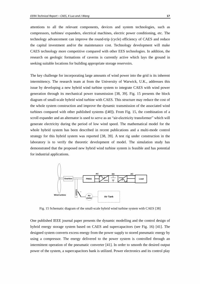
The key challenge for incorporating large amounts of wind power into the grid is its inherent
intermittency. The research team at from the University of Warwick, U.K., addresses this
issue by developing a new hybrid wind turbine system to integrate CAES with wind power
generation through its mechanical power transmission [38, 39]. Fig. 15 presents the block
diagram of small-scale hybrid wind turbine with CAES. This structure may reduce the cost of
the whole system construction and improve the dynamic transmission of the associated wind
turbines compared with other published systems ([40]). From Fig. 15, the combination of a
scroll expander and an alternator is used to serve as an “air-electricity transformer” which will
generate electricity during the period of low wind speed. The mathematical model for the
whole hybrid system has been described in recent publications and a multi-mode control
strategy for this hybrid system was reported [38, 39]. A test rig under construction in the
laboratory is to verify the theoretic development of model. The simulation study has
demonstrated that the proposed new hybrid wind turbine system is feasible and has potential
for industrial applications.
Gearbox
Wind turbine
PMSG
AC DC AC
Load
Air TankAir
motor
Clu
tch
Fig. 15 Schematic diagram of the small-scale hybrid wind turbine system with CAES [38]
One published IEEE journal paper presents the dynamic modelling and the control design of
hybrid energy storage system based on CAES and supercapacitors (see Fig. 16) [41]. The
designed system converts excess energy from the power supply to stored pneumatic energy by
using a compressor. The energy delivered to the power system is controlled through an
intermittent operation of the pneumatic converter [41]. In order to smooth the desired output
power of the system, a supercapacitors bank is utilized. Power electronics and its control play
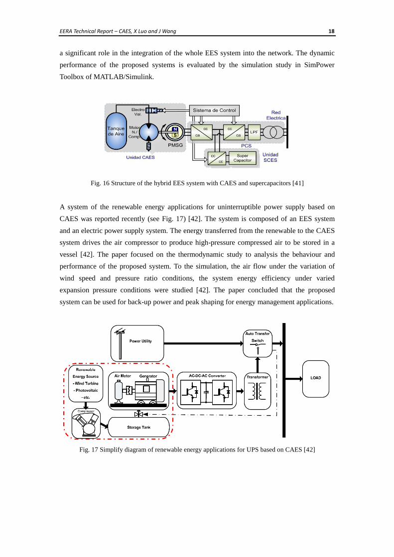
EERA Technical Report – CAES, X Luo and J Wang 18
a significant role in the integration of the whole EES system into the network. The dynamic
performance of the proposed systems is evaluated by the simulation study in SimPower
Toolbox of MATLAB/Simulink.
Fig. 16 Structure of the hybrid EES system with CAES and supercapacitors [41]
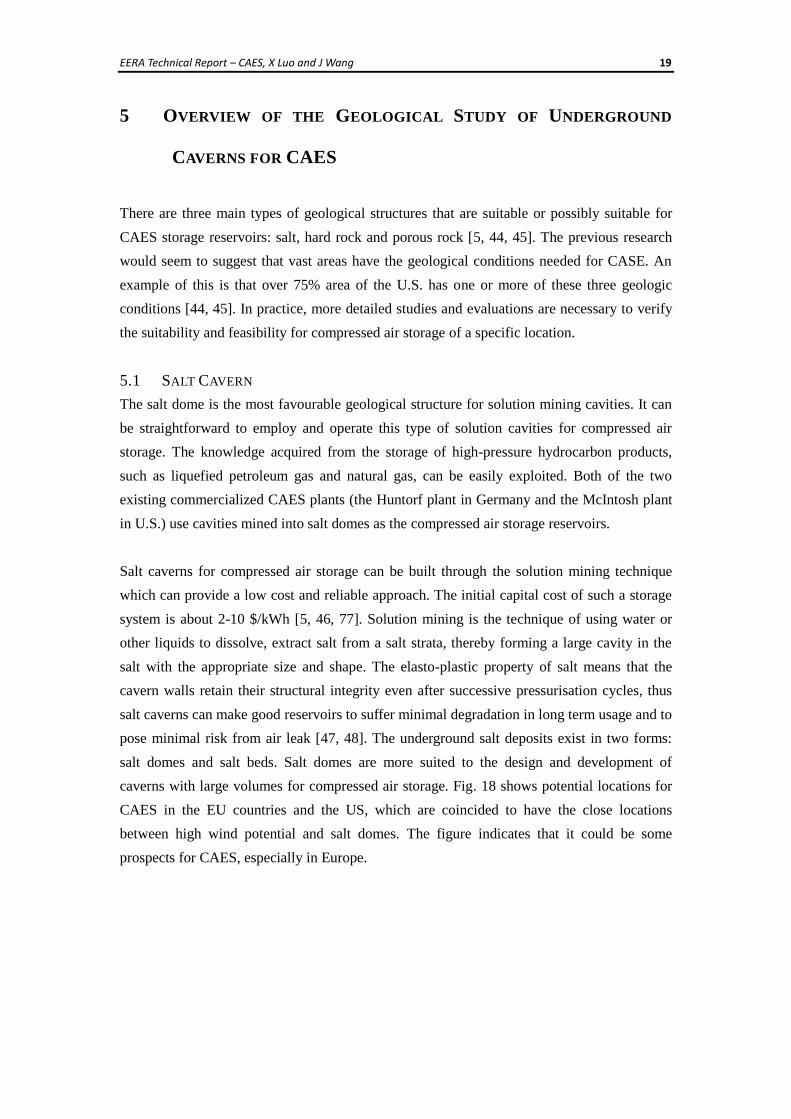
A system of the renewable energy applications for uninterruptible power supply based on
CAES was reported recently (see Fig. 17) [42]. The system is composed of an EES system
and an electric power supply system. The energy transferred from the renewable to the CAES
system drives the air compressor to produce high-pressure compressed air to be stored in a
vessel [42]. The paper focused on the thermodynamic study to analysis the behaviour and
performance of the proposed system. To the simulation, the air flow under the variation of
wind speed and pressure ratio conditions, the system energy efficiency under varied
expansion pressure conditions were studied [42]. The paper concluded that the proposed
system can be used for back-up power and peak shaping for energy management applications.
Fig. 17 Simplify diagram of renewable energy applications for UPS based on CAES [42]
EERA Technical Report – CAES, X Luo and J Wang 19
5 OVERVIEW OF THE GEOLOGICAL STUDY OF UNDERGROUND
CAVERNS FOR CAES
There are three main types of geological structures that are suitable or possibly suitable for
CAES storage reservoirs: salt, hard rock and porous rock [5, 44, 45]. The previous research
would seem to suggest that vast areas have the geological conditions needed for CASE. An
example of this is that over 75% area of the U.S. has one or more of these three geologic
conditions [44, 45]. In practice, more detailed studies and evaluations are necessary to verify
the suitability and feasibility for compressed air storage of a specific location.
5.1 SALT CAVERN
The salt dome is the most favourable geological structure for solution mining cavities. It can
be straightforward to employ and operate this type of solution cavities for compressed air
storage. The knowledge acquired from the storage of high-pressure hydrocarbon products,
such as liquefied petroleum gas and natural gas, can be easily exploited. Both of the two
existing commercialized CAES plants (the Huntorf plant in Germany and the McIntosh plant
in U.S.) use cavities mined into salt domes as the compressed air storage reservoirs.
Salt caverns for compressed air storage can be built through the solution mining technique
which can provide a low cost and reliable approach. The initial capital cost of such a storage
system is about 2-10 $/kWh [5, 46, 77]. Solution mining is the technique of using water or
other liquids to dissolve, extract salt from a salt strata, thereby forming a large cavity in the
salt with the appropriate size and shape. The elasto-plastic property of salt means that the
cavern walls retain their structural integrity even after successive pressurisation cycles, thus
salt caverns can make good reservoirs to suffer minimal degradation in long term usage and to
pose minimal risk from air leak [47, 48]. The underground salt deposits exist in two forms:
salt domes and salt beds. Salt domes are more suited to the design and development of
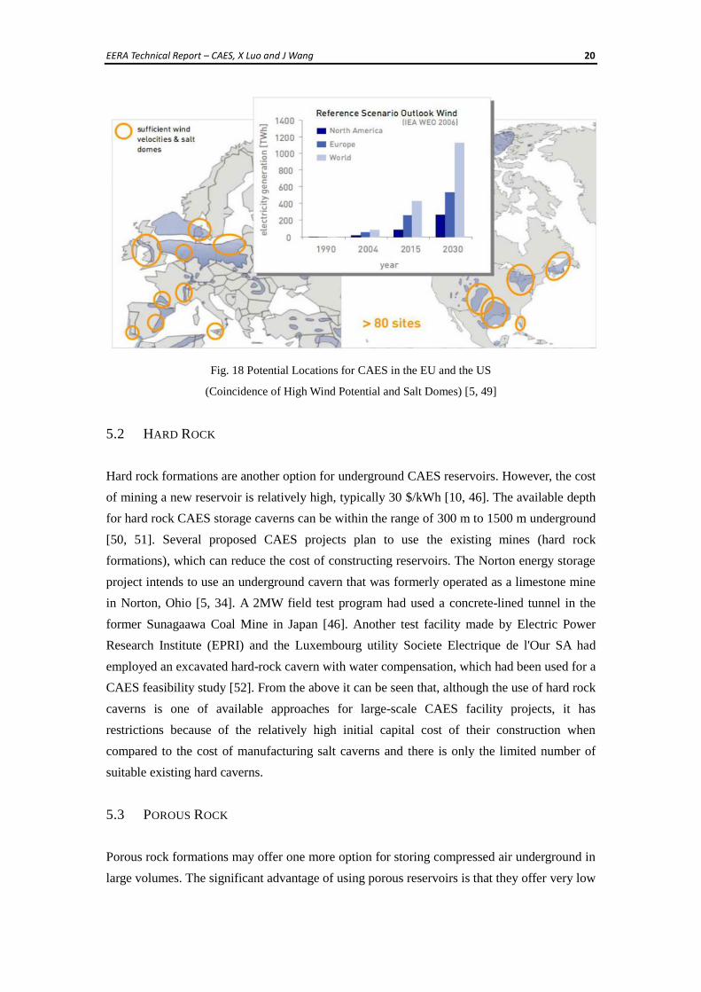
caverns with large volumes for compressed air storage. Fig. 18 shows potential locations for
CAES in the EU countries and the US, which are coincided to have the close locations
between high wind potential and salt domes. The figure indicates that it could be some
prospects for CAES, especially in Europe.
EERA Technical Report – CAES, X Luo and J Wang 20
Fig. 18 Potential Locations for CAES in the EU and the US
(Coincidence of High Wind Potential and Salt Domes) [5, 49]
5.2 HARD ROCK
Hard rock formations are another option for underground CAES reservoirs. However, the cost
of mining a new reservoir is relatively high, typically 30 $/kWh [10, 46]. The available depth
for hard rock CAES storage caverns can be within the range of 300 m to 1500 m underground
[50, 51]. Several proposed CAES projects plan to use the existing mines (hard rock
formations), which can reduce the cost of constructing reservoirs. The Norton energy storage
project intends to use an underground cavern that was formerly operated as a limestone mine
in Norton, Ohio [5, 34]. A 2MW field test program had used a concrete-lined tunnel in the
former Sunagaawa Coal Mine in Japan [46]. Another test facility made by Electric Power
Research Institute (EPRI) and the Luxembourg utility Societe Electrique de l'Our SA had
employed an excavated hard-rock cavern with water compensation, which had been used for a
CAES feasibility study [52]. From the above it can be seen that, although the use of hard rock
caverns is one of available approaches for large-scale CAES facility projects, it has
restrictions because of the relatively high initial capital cost of their construction when
compared to the cost of manufacturing salt caverns and there is only the limited number of
suitable existing hard caverns.
5.3 POROUS ROCK
Porous rock formations may offer one more option for storing compressed air underground in
large volumes. The significant advantage of using porous reservoirs is that they offer very low
EERA Technical Report – CAES, X Luo and J Wang 21
cost characteristic; it was reported that the estimated development cost is approximately
0.10-0.11 $/kWh [5, 46].
Several feasibility study projects of porous rock for CAES had been attempted. Enel, Italy’s
largest power company, operated a 25 MW porous rock-based CAES research facility plant in
Sesta using a porous rock storage that had previously held carbon dioxide near a geothermal
region [46]. Although the initial air cyclic testing was successful, additional testing was
stopped due to a disturbed geothermal event. Strata Power, EPRI, Nicor, and U.S.
Development of Energy (DOE), had tested the porous sandstone caverns in Pittsfield, Illinois
to determine the feasibility of using the porous rock formations there for storing compressed
air. The test results indicated that compressed air can be stored and cycled successfully in the
St. Peter sandstone underneath the Pittsfield site. However, the period for air storage was
limited as the stored compressed air would react with local pyrites in the sandstone [53]. The
Iowa Stored Energy Park project described above aimed to use porous sandstone aquifers in
Iowa. Unfortunately, this project was stopped in 2011, and the main reason for its termination
was the lack of geological structures that would allow the compressed air to flow efficiently
to match the specifications for building CAES plants [29, 30].
From the above description, although there is a potential for using porous rock formations for
underground CAES, it still requires extensive research into the geologic characteristics of the
porous rock at the candidate sites to determine their feasibilities.
5.4 GEOLOGICAL INVESTIGATION IN THE UK
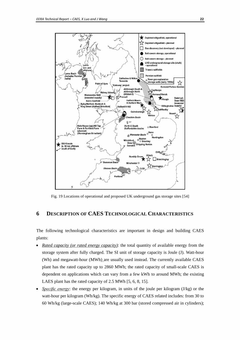
The distribution of the possible underground storage sites in the UK are shown in Fig. 19
which sourced from a report by a foresight project looking at the potential sites for natural gas
storage. The potential areas mainly lie in parts of England and Northern Ireland [54]. It is
seen that there are limited areas suitable for building salt caverns for underground CAES in
the UK.
EERA Technical Report – CAES, X Luo and J Wang 22
Fig. 19 Locations of operational and proposed UK underground gas storage sites [54]
6 DESCRIPTION OF CAES TECHNOLOGICAL CHARACTERISTICS
The following technological characteristics are important in design and building CAES
plants:
Rated capacity (or rated energy capacity): the total quantity of available energy from the
storage system after fully charged. The SI unit of storage capacity is Joule (J). Watt-hour
(Wh) and megawatt-hour (MWh) are usually used instead. The currently available CAES
plant has the rated capacity up to 2860 MWh; the rated capacity of small-scale CAES is
dependent on applications which can vary from a few kWh to around MWh; the existing
LAES plant has the rated capacity of 2.5 MWh [5, 6, 8, 15].
Specific energy: the energy per kilogram, in units of the joule per kilogram (J/kg) or the
watt-hour per kilogram (Wh/kg). The specific energy of CAES related includes: from 30 to
60 Wh/kg (large-scale CAES); 140 Wh/kg at 300 bar (stored compressed air in cylinders);
EERA Technical Report – CAES, X Luo and J Wang 23
214 Wh/kg (LAES) [5, 55].
Specific power (or power-to-weight ratio): the amount of obtained power per kilogram of a
storage medium, in the unit of the watt per kilogram (W/kg). It is an important parameter
measuring EES requirements for (hybrid) electric vehicles and other weight limited power
sources. There is no available data to specific power of CAES.
Energy density: the amount of energy stored per unit volume in a given system or region of
space, in the watt-hour per cubic metre (Wh/m3); to various types of batteries or liquid
fuels, normally in the watt-hour per litre (Wh/L). In EES applications, the energy density
relates to the volume of the storage reservoir, e.g. a cylinder or a fuel tank. To the same
amount of volume, the higher the energy density of the storage medium is chosen, the
more the energy can be stored or transported. The energy density of CAES is 2-6 Wh/L
depending on air pressure, and the energy density of LAES is four times than that of
CAES [2, 56].
Power density: the amount of power per unit volume, usually expressed in the units of the
watt per cubic metre (W/m3) or the watt per litre (W/L). It is the rate of power on the basis
of volume, which can be taken from an energy source. The power density of CAES is
within the range from 0.5 to 2 W/L [6].
Power rating: To an EES system, the power rating indicates the maximum rate at which
the system can discharge energy, expressed in the units of kilowatt (kW) or megawatt
(MW). The power ratings to CAES related are: up to ~1000 MW (large-scale CAES); from
a few of kW to a few of MW (small-scale CAES); up to 200 MW (LAES) [7, 57, 58].
Part-load operation: The CAES plant has the high part-load operation ability, which
makes it well suited for cooperative work with variable power sources such as wind power
generation [5]. The CAES facility output can be controlled by adjusting the airflow rate
with inlet temperatures keeping constant at the multi-expansion stage, which leads to
better heat utilization and higher efficiency during part-load operation compared to a
conventional (gas) turbine system [63].
Discharge time duration at power rating: to an EES system, the amount of time that the
system must be able to discharge, at the system power rating, without recharging [57]. The
discharge time duration, as a characteristic of system adequacy, is determined by the depth
of discharge and operational conditions of the system. To CAES related, the discharge time
duration can have: up to ~26 hours (large-scale CAES); up to around 1-2 hour (small-scale
CAES); from 1 to 12 hours (LAES) [5, 23, 59].
Response time: The response time of a large-scale CAES plant can be faster than that of an
equivalent gas turbine plant. The McIntosh plant can increase or decrease around 18MW
per minute, which is about 60% higher than a comparable typical gas turbine facility [27].
The proposed Matagorda Plant is designed to be able to bring its 4×135 MW power train
modules to full power in 14 minutes (or 7 minutes for an emergency start) [10]. The
EERA Technical Report – CAES, X Luo and J Wang 24
response time of the small-scale CAES can be quicker (from seconds to minutes) than that
of large-scale CAES and LAES (minutes).
Self-discharge rate: indicates how long storage system takes to discharge when the system
unused. Self-discharge can be caused by the liquid, gas or electromagnetic leakages and
the heat dissipation. The self-discharge rates to CAES and LAES are both quite small [5, 7,
59].
Heat rate: The heat rate indicates the fuel consumed per kWh of output for a CAES plant
[10]. Heat rates for CAES systems without a heat recovery system are typically 5500-6000
kJ/kWh Lower Heating Value (LHV) and heat rates with a recuperator are typically
4200-4500kJ /kWh LHV [5, 63]. The Huntorf plant, with a rated output of 290 MW over 3
hours and an overall efficiency of 42%, has a heat rate of 5870 kJ/kWh LHV; the
McIntosh plant recuperates the turbine exhaust heat, thus improving the overall efficiency
to 53%, with a heat rate of 4330 kJ/kWh LHV [5, 64].
Recharge rate: the rate at which power can be pushed for storage, for instance, a battery
storage system may take 10 hours to deplete and 14 hours to refill [57]. To a CAES system,
the recharge rate can be described as the quantity of compressed air per unit of time that
replenishes a reservoir or a cavern.
Lifetime: the service time of a unit or a system. To EES systems, it usually uses the number
of year as its unit. It varies with technology and intensity of use. The PHS system has the
longest lifetime in EES systems, approximately up to 50 years; the CAES and LAES
systems have around from 20 to 40 years of lifetime [5, 57, 59, 60].
Cycling times (or cycle life): the number of times at which the EES system can be loaded
and unloaded, that is, the total number of cycles of completing common charge and
discharge cycles [57]. Normally, with the different rates of discharge depth, the cycling
times varies. To CAES, the cycling times of large-scale CAES is 8000-12000; also, the
small-scale compressed air battery system had been tested, about 30,000 stop/start
operations [7, 61].
CAES reservoir operation methods: According to the geological conditions, the operation
methods for the compressed air reservoir of a large-scale CAES system mainly consists of
two approaches as follows [5, 10, 62, 63]:
(1) Constant volume: the storage volume is fixed and the reservoir is operated over an
appropriate pressure range. In this mode, there are two design options to control the
reservoir output: a) the output pressure of reservoir is varied and then it can design a
proper system to allow the high-pressure turbine inlet pressure to vary following with the
reservoir output pressure; b) in the case of the reservoir output pressure varying, it can
keep the inlet pressure of the high-pressure turbine constant by throttling the upstream
valve to a fixed pressure. Both two existing CAES plants use this method. The Huntorf
CAES plant is designed to throttle the air to 46 bar at the high-pressure turbine inlet (with
EERA Technical Report – CAES, X Luo and J Wang 25
the cavern operating between 48 to 66 bar) and the McIntosh system similarly throttles
the air to 45 bar (with the cavern operating between 45 and 74 bar).
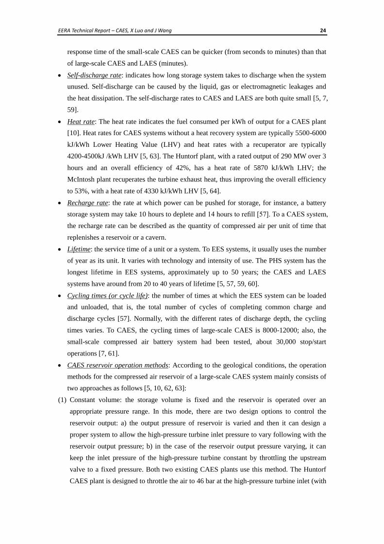
(2) Constant pressure: it may be possible to keep the storage reservoir at constant pressure
throughout operation by using a water compensation system by employing an
aboveground reservoir (Fig. 20).
Water compensation system
CAES plant
Fig. 20 Schematic diagram of CAES plant with constant-pressure compensation system [65]
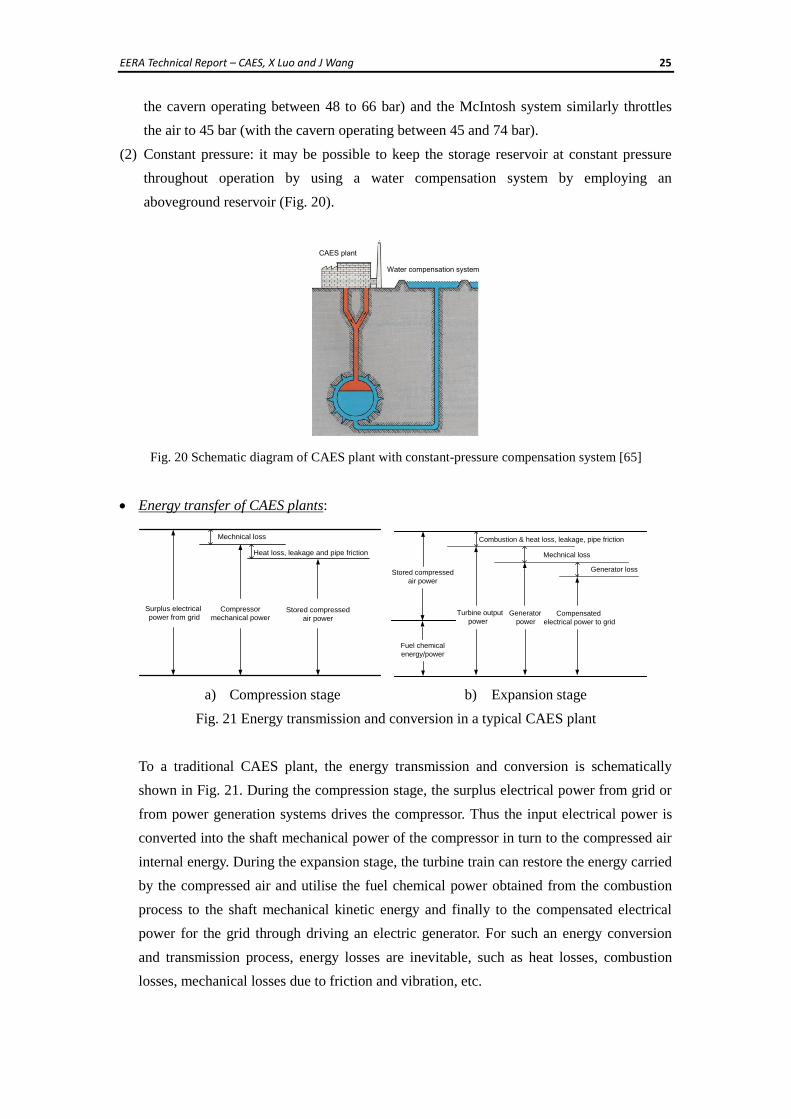
Energy transfer of CAES plants:
Surplus electrical
power from gridCompressor
mechanical power
Mechnical loss
Heat loss, leakage and pipe friction
Stored compressed
air power
Stored compressed
air power
Turbine output
power
Mechnical loss
Generator
powerCompensated
electrical power to grid
Generator loss
Fuel chemical
energy/power
Combustion & heat loss, leakage, pipe friction
a) Compression stage b) Expansion stage
Fig. 21 Energy transmission and conversion in a typical CAES plant
To a traditional CAES plant, the energy transmission and conversion is schematically
shown in Fig. 21. During the compression stage, the surplus electrical power from grid or
from power generation systems drives the compressor. Thus the input electrical power is
converted into the shaft mechanical power of the compressor in turn to the compressed air
internal energy. During the expansion stage, the turbine train can restore the energy carried
by the compressed air and utilise the fuel chemical power obtained from the combustion
process to the shaft mechanical kinetic energy and finally to the compensated electrical
power for the grid through driving an electric generator. For such an energy conversion
and transmission process, energy losses are inevitable, such as heat losses, combustion
losses, mechanical losses due to friction and vibration, etc.
EERA Technical Report – CAES, X Luo and J Wang 26
Efficiencies: there are mainly two types of efficiencies which have been considered in
energy storage systems. One is energy conversion efficiency, also named energy efficiency.
It is defined as the ratio between the useful output of an energy conversion machine from
the CASE system and the input in energy terms [60, 61]. The input or useful output could
be electric energy, mechanical work, heat energy, chemical energy, etc. [60]. Charge and
discharge efficiencies normally contribute to the energy efficiency. Another is round-trip
efficiency, also referred to as cycle efficiency [6, 57, 62]. It is the percentage to indicate
the amount of energy output from an energy storage system for each unit of energy input
[5, 62]. A unit with 70% round-trip efficiency means the energy storage system can return
7 kWh of energy for every 10 kWh put into storage.
The situation is more complicated for analysing the energy performance of conventional
CAES plants due to the presence of two substantial different energy inputs. On the one
hand, the input electrical energy is used to drive the compressors; on the other hand, the
fuel energy released in the combustion process is used to increase the air internal energy
prior to expansion. Thus it is necessary to express both the fuel and compressor electricity
on an equivalent energy basis. The roundtrip efficiency for CAES facilities can be:
)()( inputenergyoutputenergyRT [5, 6, 10]. To the traditional large-scale CAES plants,
energy output is the output electrical power of generator ( TE ) in the CAES plant, and an
“effective” energy input is employed for efficiency calculation:
ngngcompressor EEinputenergy ,where compressorE is the electricity energy consumed by
compressors, the second term (ngng E ) is the amount of electricity that could have been
made from the same fuel energy used in the CAES unit (ngE ) and the fuel had been used
to make electricity in a stand-alone power plant at efficiency (ng ) instead of using the fuel
to fire in a CAES unit [5, 10]. To the AA-CAES plants and small-scale CAES facilities,
energy input is purely the electrical power for driving compressors. From the published
literature, the efficiencies related to CAES were reported to have different figures as
follows:
1) the discharge efficiency (i.e., the energy efficiency from the compressed air energy to
electric energy) of conventional large-scale CAES is about 70-79% [72]; the
discharge efficiency of small-scale CAES can be approximately 75-90% [24].
2) the two existing commercial CAES plants, the Huntorf plant has an roundtrip
efficiency of 42%; the roundtrip efficiency of the McIntosh plant, with the
consideration of heat recuperation, is about 53~54% [5, 6, 11, 12, 16];
3) the system based on the new CAES concept without involving fossil fuel combustion,
such as AA-CAES, the roundtrip efficiency can achieve up to around 70%, which can
EERA Technical Report – CAES, X Luo and J Wang 27
be similar to PHS [13, 26, 28].
Operation switching time: To the two existing large-scale CAES plants, the turbine
normally brings the machinery train to start rotation and speed up until synchronization,
and then the turbine is shut down [5]. Thus the turbine needs to be engaged for operation
at both the compression and expansion (electricity generation) modes. At the Huntorf
CAES facility, the switch from one operating mode to another requires a minimum of 20
minutes [10]. This switching time may affect and limit the CAES plant application for
balancing rapid fluctuations. One possible solution is to redesign the overall system
structure by separating the compression and turbo expander components rather than
linking them through a common shaft via the clutch mechanisms as in the McIntosh and
Huntorf plants [5, 10, 11]. This design concept has been considered in the advanced CAES
plants.
Operational constraints: relevant to operational or working conditions (e.g. flow rate,
temperature and pressure) and/or the safety issues (such as explosions, waste and bursting
of a flywheel) [1]. As a function of energy needs, these constraints can influence the
selection of a suitable technology used for a specific EES application. The Iowa Stored
Energy Park project is a practical example: it had to stop in 2011 due to the airflow rate
cannot satisfy the specifications of the proposed CAES plant requirements [30].
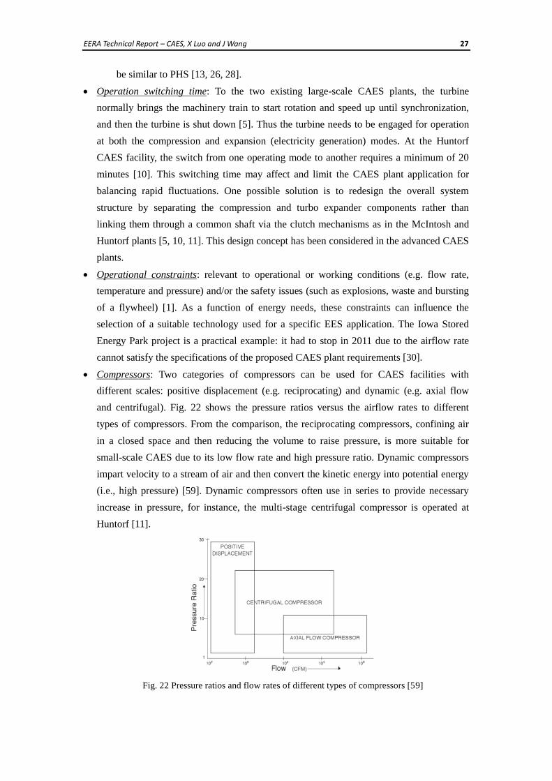
Compressors: Two categories of compressors can be used for CAES facilities with
different scales: positive displacement (e.g. reciprocating) and dynamic (e.g. axial flow
and centrifugal). Fig. 22 shows the pressure ratios versus the airflow rates to different
types of compressors. From the comparison, the reciprocating compressors, confining air
in a closed space and then reducing the volume to raise pressure, is more suitable for
small-scale CAES due to its low flow rate and high pressure ratio. Dynamic compressors
impart velocity to a stream of air and then convert the kinetic energy into potential energy
(i.e., high pressure) [59]. Dynamic compressors often use in series to provide necessary
increase in pressure, for instance, the multi-stage centrifugal compressor is operated at
Huntorf [11].
Fig. 22 Pressure ratios and flow rates of different types of compressors [59]
EERA Technical Report – CAES, X Luo and J Wang 28
Construction constraints: related to geographic limitations and/or environmental
requirements. For instance, the large-scale underground CAES systems require the natural
storage reservoir; the solar fuel generation usually need at an area with relatively high
solar densities. These constraints can affect the selection of an appropriate EES technology
for applications.
Environmental aspect: the environmental issues must be considered as important factor for
any new builds. The traditional CAES plants consume the fossil fuels which will definitely
lead to CO2 emissions. AA-CAES, small-scale CAES and LAES cannot employ gas
turbines in the expansion mode to make the system environmental friendly. The impact of
geological storage to the environment in a long term needs to be closely monitored.
Other technical characteristics: The suitable storage duration for CASE can be from a few
hours to several months because its self-discharge is very small. In addition, to the CAES
plants, because compression energy is supplied separately at different time, the full output
of the turbine can be used to generate electricity during expansion, whereas conventional
gas turbines typically use two thirds of the output power from the expansion stage to run
the compressor during their working processes [5, 10].
Limitations:
1) Similar to the PHS, the major barrier to implement the underground CAES plant is to
seek appropriate geographical storage locations. So far, it is possible to build a CAES
plant nearby salt caverns, hard rock and porous rock formations. In practice, the mature
experience on constructing large-scale storage reservoirs is only in using mined cavities
in salt domes.
2) Traditional large-scale CAES plants require to combust diminishing fossil fuels, which
will lead to carbon oxide emissions and environmental pollutions. To avoid the
involvement of fossil fuel in CAES, some advanced CAES concepts are under the
research and development stage, such as AA-CAES.
7 ECONOMIC ANALYSIS BRIEF
The economic study to an EES technology is important and there has been continuously study
reported year by year. The cost of storage technologies is changing with the continuous
development of technology and the trend shows that the cost is normally getting cheaper with
technology advancement. The paper ([64]) presents the overview of cost data for 25 MW to
220 MW CAES plants but it is outdated (published almost 30 years ago). A complete
economic analysis needs to consider not only the capital cost but also the Operating &
Maintenance (O&M) costs and the impact of the equipment life. The cost data to CAES
related technology is described below.
EERA Technical Report – CAES, X Luo and J Wang 29
Energy capital cost and power capital cost: the initial investment costs, usually expressed in
the units of dollars per kilowatt-hour ($/kWh) and dollars per kilowatt ($/kW) respectively.
The initial cost includes the spending on design, specification, civil works, and installation
[1, 59]. Specifically to CAES and LAES, the reported data related to the power capital cost
are: 1300-1550 $/kW (small-scale CAES), 400-1000 $/kW (large-scale CAES); 900-2000
$/kW (LAES); the reported data related to the energy capital cost have: 200-250 $/kWh
(small-scale CAES), up to 120 $/kWh (large-scale CAES), 260-530 $/kWh (LAES) [6, 58,
66-68]. From the data, it can be seen that the cost relies on the scale. Among the mature
and developed EES techniques, PHS and CAES have quite low energy capital costs
compared to other technologies. Also it is worth mentioning that, to the underground
large-scale CAES, normally 50-60% and even more of the capital cost will be spent on the
construction of storage reservoirs [5]. From the above description of geological study, it
can be seen that, to different geological formations, the cost can be quite different. In
addition, the capital cost to a specific CAES system can be various from the data in cited
references here due to, for example, the time of construction, the location of the
plant/facility, and the size of the system.
Operating and maintenance cost: the costs in dollars per kilowatt-hour ($/kWh) for periodic
inspection, fuelling, maintenance (e.g. adding lubricating oil), mechanical component
replacements (such as seals and bearings) and electrical component replacements (such as
wires and fuses), recalibration, clearing if need, etc. The operating and maintenance cost of
CAES is 19-25$/kW per year [69]. The cost to LAES should be slightly higher than CAES
due to its more complex process leading to the more components required.
8 APPLICATION POTENTIALS
From the characteristics of CAES, CAES facilities can be built in multi-scale ranges. The
large-scale CAES plant can have the scale of up to 1000MW power rating [6, 7]. Thus CAES
can be used for grid-scale energy management in supporting load shifting, peak shaving and
load levelling.
Small-scale CAES can be used as an alternative to replace traditional chemical batteries and
mechanical flywheels in back-up power and UPS applications. Also, with the features of
moderate responses and good partial load operations, CAES offers strong potential for
integration with intermittent renewable energy power generation to provide back-up power.
The possibility is being considered and has attempted to integrate the CAES facility with the
wind farm, such as the developing ADELE AA-CAES project in Germany. Table 1
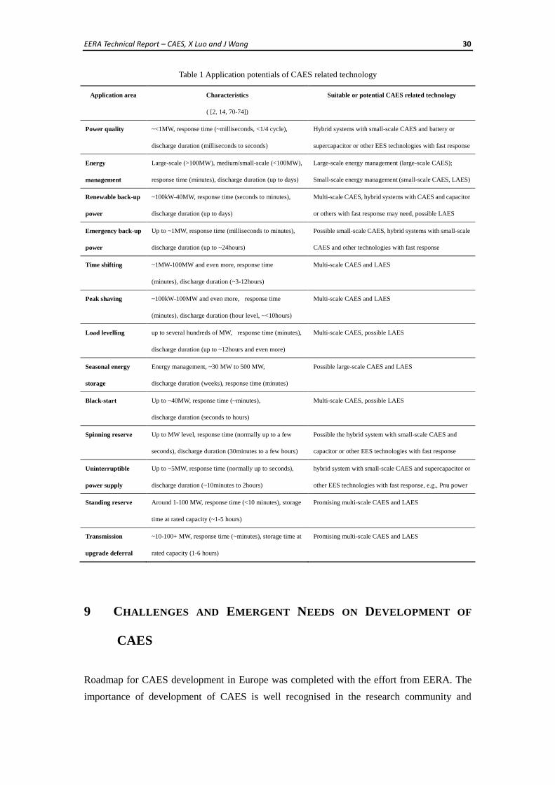
summarizes and predicts the industry and the power grid applications of CAES.
EERA Technical Report – CAES, X Luo and J Wang 30
Table 1 Application potentials of CAES related technology
9 CHALLENGES AND EMERGENT NEEDS ON DEVELOPMENT OF
CAES
Roadmap for CAES development in Europe was completed with the effort from EERA. The
importance of development of CAES is well recognised in the research community and
Application area Characteristics
( [2, 14, 70-74])
Suitable or potential CAES related technology
Power quality
~<1MW, response time (~milliseconds, <1/4 cycle),
discharge duration (milliseconds to seconds)
Hybrid systems with small-scale CAES and battery or
supercapacitor or other EES technologies with fast response
Energy
management
Large-scale (>100MW), medium/small-scale (<100MW),
response time (minutes), discharge duration (up to days)
Large-scale energy management (large-scale CAES);
Small-scale energy management (small-scale CAES, LAES)
Renewable back-up
power
~100kW-40MW, response time (seconds to minutes),
discharge duration (up to days)
Multi-scale CAES, hybrid systems with CAES and capacitor
or others with fast response may need, possible LAES
Emergency back-up
power
Up to ~1MW, response time (milliseconds to minutes),
discharge duration (up to ~24hours)
Possible small-scale CAES, hybrid systems with small-scale
CAES and other technologies with fast response
Time shifting
~1MW-100MW and even more, response time
(minutes), discharge duration (~3-12hours)
Multi-scale CAES and LAES
Peak shaving
~100kW-100MW and even more, response time
(minutes), discharge duration (hour level, ~<10hours)
Multi-scale CAES and LAES
Load levelling
up to several hundreds of MW, response time (minutes),
discharge duration (up to ~12hours and even more)
Multi-scale CAES, possible LAES
Seasonal energy
storage
Energy management, ~30 MW to 500 MW,
discharge duration (weeks), response time (minutes)
Possible large-scale CAES and LAES
Black-start
Up to ~40MW, response time (~minutes),
discharge duration (seconds to hours)
Multi-scale CAES, possible LAES
Spinning reserve
Up to MW level, response time (normally up to a few
seconds), discharge duration (30minutes to a few hours)
Possible the hybrid system with small-scale CAES and
capacitor or other EES technologies with fast response
Uninterruptible
power supply
Up to ~5MW, response time (normally up to seconds),
discharge duration (~10minutes to 2hours)
hybrid system with small-scale CAES and supercapacitor or
other EES technologies with fast response, e.g., Pnu power
Standing reserve
Around 1-100 MW, response time (<10 minutes), storage
time at rated capacity (~1-5 hours)
Promising multi-scale CAES and LAES
Transmission
upgrade deferral
~10-100+ MW, response time (~minutes), storage time at
rated capacity (1-6 hours)
Promising multi-scale CAES and LAES
EERA Technical Report – CAES, X Luo and J Wang 31
industrial sectors. However, the challenges present and questions are not yet answered:
• What technical performance can be achievable by CAES by 2020/30/40/50?
• What cost levels are achievable for CAES systems in the long-term?
• What developments are required to achieve the above performance and costs?
• Over what time-scale might the technical breakthroughs happen and what will they
cost?
• How to clarify the economic benefits from CAES and the related quantitative
analysis?
• What are needed for stimulating and supporting innovation in CAES technology
development?
Need for cooperation: Development of a complete CAES system especially to large-scale
CAES is very challenging for any one company to tackle. The mechanism is urgently
required to accommodate cooperation between complementary companies. Some
obviously complementary areas are: compression/expansion machines, thermal storage &
heat transfer, high pressure air storage and electromechanical power-conversion and grid
interfacing. Also, it is necessary to galvanise some of the European world-leading
turbo-machinery companies into developing products to address CAES market and thereby
prepare to become world market leaders in this area.
Needs for new technologies in air compressors/expanders: Pnu-Power has shown an excellent
example for the importance of new technology development. Without adopting the
advanced efficient scroll air expander technology, it is impossible to have the market
acceptable product – Compressed Air Battery. Technical innovations and technology
breakthrough are essential, especially for compressor and turbine technology, such as
developing improved sealing methods for compression & expansion machinery to
suppress internal leakage and discovering approaches to minimise losses associated with
secondary flows in compressors and turbines.
Need substantial improvement in efficiency: Compressed air is traditionally famous for its low
efficiencies, which will no doubt affect its competitiveness and feasibility. The Huntorf
plant has a cycle efficiency of 42%; the cycle efficiency of the McIntosh plant is about
53~54% [5, 6]. The low efficiencies of CAES result from the heat losses in the
compression and expansion modes, the air leakage throughout the whole CAES system,
the internal energy losses due to the air compressibility, etc. AA-CAES combined with
thermal energy storage, which can reduce the heat losses, expects to achieve up to 70% of
cycle efficiency. Effective turnaround efficiencies of >70% are certainly achievable by
2020. Values up to 80% will be achievable before 2030.
Need for the software tools for complete system analysis and integration with grid operation:
A modelling tool for complete system simulation will help understand the whole system
dynamics, efficiency improvement, operation optimisation. While a CAES system is
EERA Technical Report – CAES, X Luo and J Wang 32
connected with the grid or is imposed into the framework of smart grid operation, the tool
will assist to design optimised control and operation strategy.
Need for reduction in cost of constructing air reservoirs: Reducing the construction cost of
building large-scale underground cavities or over-ground reservoirs is challenging.
Normally, more than 60% of the capital cost invested on building a CAES plant comes
from the construction of the air reservoir.
Need for a clear map of underground storage resources: The large-scale CAES plant needs to
seek appropriate geographical storage locations. It is important to conduct research and
survey to gain a clearer picture of natural resources suitable for CAES and mapping the
locations of storage and renewable energy sources. Currently, the mature experience on
constructing large-scale storage reservoirs is only in using mined cavities in salt domes.
The research is required to identify alternative suitable geologic structure for CAES and to
develop lower-cost methods for building cavern formations.
Need for study of the potential environmental impact: The long term impact of underground
storage to the environment should be assessed. It might cause competition with natural gas
or CO2 storage while the limited storage resources are used for CAES as well. Also,
current operating large-scale CAES plants require to combust diminishing fossil fuels,
which will lead to carbon oxide emissions and environmental pollutions. AA-CAES and
small-scale CAES normally have not this issue.
10 CONCLUDING REMARKS
This report provides an overview of the state-of-the-art of CAES technology development. It
is found that the costs and performance largely depend on the scales; in general, with the
same types of components in a CAES systems, large scale results in more efficient
performance and lower cost. Small scale CAES systems offer a combination of good
performance, long lifetime, low net environmental impact and reasonable cost compared to
rechargeable batteries. There are huge application potentials for CAES in strengthening
various aspects of electric power system reliable operations, however, the enormous
challenges and barriers present for further deployment. Funding support and joint effort from
academic and industrial sectors are required to speed up the technology innovation and
breakthrough to realize the great potential of CAES and demonstrate its role in supporting
power system operation.
EERA Technical Report – CAES, X Luo and J Wang 33
REFERENCES
[1] H. Ibrahim, A. Ilinca, and J. Perron, “Energy storage systems—characteristics and comparisons”,
Renewable and Sustainable Energy Reviews, vol. 12, no. 5, pp. 1221–1250, 2008.
[2] “Electrical energy storage: white paper”, Energy Storage team, IEC Market Strategy Board, 2011.
[Online]. Available at: http://www.iec.ch/whitepaper/pdf/iecWP-energystorage-LR-en.pdf.
[Accessed: 15-Sept-2012].
[3] D. Pavlov, “Lead-acid Batteries: science and technology: a handbook of lead-acid battery
technology and its influence on the product”, Elsevier Science, pp. 3-28. 2011.
[4] B. J. Davidson, et al., “Large-scale electrical energy storage”, Physical Science, Measurement and
Instrumentation, Management and Education Reviews, IEE Proceedings A, vol. 127, no. 6, pp.
345–385, 1980.
[5] S. Succar, R.H. Williams, “Compressed air energy storage: theory, resources, and applications for
wind power”, technical report, Energy Systems Analysis Group, Princeton Environmental
Institute, Princeton University, 2008.
[6] H. Chen, T. N. Cong, W. Yang, C. Tan, Y. Li, and Y. Ding, “Progress in electrical energy storage
system: A critical review”, Progress in Natural Science, vol. 19, no. 3, pp. 291–312, 2009.
[7] “Compressed air battery systems”, [Online]. Available at: http://www.flowbattery.co.uk/.
[Accessed: 08-Oct-2013].
[8] E. Gent, “Liquid air energy storage could become £1bn industry”, Engineering and Technology
Magazine, May 2013, [Online]. Available at: http://eandt.theiet.org/news/2013/may/liquid-air.cfm.
[Accessed: 08-July-2013].
[9] I. Koutsopoulos, V. Hatzi, and L. Tassiulas, Optimal energy storage control policies for the smart
power grid, The Proceedings of IEEE International Conference on Smart Grid Communications,
pp. 475–480, 2011.
[10] S. Samir, “Large energy storage systems handbook”, edited by Jonah G . Levine, CRC Press, pp.
112-152, 2011.
[11] E.ON, “Huntorf power plant”, [Online]. Available at: http://www.kraftwerk-wilhelmshaven.com/
pages/ekw_en/Huntorf_Power_Plant/Media_Center/index.htm. [Accessed: 01-Nov-2012].
[12] M. Nakhamkin, M. Chiruvolu, “Available Compressed Air Energy Storage (CAES) plant
concepts”, 2007. [Online]. Available at: http://www.enstpo.com/content/library/PowerGen_
2007_ paper.pdf. [Accessed: 04-Oct-2012].
[13] ConvenEnergy Storage & Power LLC, “CAES – advanced generation”, “Adiabatic CAES
concept”, [Online]. Available at: http://www.enstpo.com/. [Accessed: 04-Oct-2012].
[14] F. Díaz-González, A. Sumper, O. Gomis-Bellmunt, and R. Villafáfila-Robles, “A review of energy
storage technologies for wind power applications”, Renewable and Sustainable Energy Reviews,
vol. 16, no. 4, pp. 2154–2171, 2012.
EERA Technical Report – CAES, X Luo and J Wang 34
[15] “Highview power storage – liquid fluid storage”, [Online]. Available at:
http://highview-power.com/ wordpress/. [Accessed: 12-Oct-2013].
[16] “CAES overview”, [Online]. Available at: http://www.apexcaes.com/caes. [Accessed:
16-Oct-2013].
[17] “Kraftwerk Huntorf”, [Online]. Available at: http://de.wikipedia.org/wiki/Kraftwerk_Huntorf.
[Accessed: 19-Oct-2013].
[18] “A/C scroll compressor”, [Online]. Available at: http://www.gasgoo.com/auto-products/
hvac-parts-347/4921.html. [Accessed: 24-Oct-2013].
[19] B. Wang, X. Li, W. Shi, “A general geometrical model of scroll compressors based on discretional
initial angles of involutes”, International Journal of Refrigeration, vol. 28, pp. 958-966, 2005.
[20] J. Wang, L. Yang, X. Luo, S. Mangan, J.W. Derby, “Mathematical modelling study of scroll air
motors and energy efficiency analysis - Part I”, IEEE/ASME Trans. on Mechatronics, vol. 16, pp.
112-121, 2011.
[21] J. Wang, X. Luo, L. Yang, L. M. Shpanin, N. Jia, S. Mangan, and J. W. Derby, “Mathematical
Modeling Study of Scroll Air Motors and Energy Efficiency Analysis—Part II”, IEEE/ASME
Transactions on Mechatronics, vol. 16, no. 1, pp. 122–132, 2011.
[22] T. Yanagisawa, “Performance of an oil-free scroll-type expander”, technical report, Institution of
Mechanical Engineers, Fluid Machinery Group, Institution of Mechanical Engineers, City
University, London, U.K., 2003.
[23] “Pnu Power – clean & reliable backup power”, Energetix Group, Presentation at CAES Workshop
at the University of Warwick, Sep., 2013.
[24] “Pnu Power - compressed air UPS systems”, [Online]. Available at: http://www.pnu-power.com/.
[Accessed: 08-Oct-2012].
[25] “Air User: Socomec Limited, Air-powered generator system installed at Stockport Pyramid.”
[Online]. Available at: http://www.airuser.com/stories/articles/-/2012/aug_2012/air_powered_
generator_system_installed_at_stockport_pyramid/. [Accessed: 08-Oct-2012].
[26] RWE power, “ADELE – Adiabatic compressed-air energy storage (CAES) for electricity supply”,
[Online]. Available at: http://www.rwe.com/web/cms/en/365478/rwe/innovation/projects-
technologies/energy-storage/project-adele/. [Accessed: 07-Nov-2012].
[27] University of California, “2020 strategic analysis of energy storage in California”, [Online].
Available http://www.energy.ca.gov/2011publications/CEC-500-2011-047/CEC-500-2011-047.pdf.
[Accessed: 08-Oct-2012].
[28] M. Finkenrath, S. Pazzi, M. D’Ercole, et al., Status and technical challenges of advanced
Compressed Air Energy Storage (CAES) technology, International Workshop on Environment and
Alternative Energy, Munich, Germany, 2009.
[29] H. Dan, “Scrapped Iowa project leaves energy storage lessons”, [Online]. Available at:
http://www.midwestenergynews.com/2012/01/19/scrapped-iowa-project-leaves-energy-storage-le
ssons/. [Accessed: 17-Sep-2012].
EERA Technical Report – CAES, X Luo and J Wang 35
[30] “Lessons from Iowa: development of a 270 megawatt compressed air energy storage project in
Midwest independent system operator: a study for the DOE energy storage systems program”,
[Online]. Available at: http://www.lessonsfromiowa.org/download-lessons/. [Accessed: 23-Sep-
2012].
[31] A. Jeannine, “Iowa compressed air storage project fails, but leaves some lessons, hopes for future
bulk energy storage - Public Power Daily - Public Power Media.” [Online]. Available at:
http://www. publicpower.org/Media/daily/ArticleDetail.cfm?ItemNumber=33842. [Accessed:
03-Oct-2012].
[32] E. Gent, “Liquid air energy storage could become £1bn industry”, Engineering and Technology
Magazine, May 2013, [Online]. Available at: http://eandt.theiet.org/news/2013/may/liquid-air.cfm.
[Accessed: 08-July-2013].
[33] R. Cockerill, “Two liquid air projects through to feasibility stage of competition”, 12 May 2013,
[Online]. Available at: http://www. gasworld.com/news/two-liquid-air-projects-through-to-
feasibility-stage-of-competition/2002149.article. [Accessed: 04-July-2013].
[34] S. Linden, Review of CAES systems development and current innovations that could bring
commercialization to fruition, The Proceedings of Electrical Energy Storage Applications &
Technology Conference, San Francisco, 2007.
[35] “Future of energy storage: technologies and policy”, a report of UK-China workshops produced
by the Chinese Academy of Sciences and the Royal Academy of Engineering, [Online]. Available
at: http://www.raeng.org.uk/news/publications/list/default.htm?TypeID=2&Item=15. [Accessed:
07-Nov-2012].
[36] The Institute of Engineering Thermophysics Chinese Academy of Sciences, [Online]. Available at:
http://www.etp.ac.cn/jgsz/kybm/kybm6/. [Accessed: 07-Nov-2012].
[37] “Comanche peak nuclear power plant, units 3 & 4 COL Application, part 3 - environmental
report”, [Online]. Available at: http://pbadupws.nrc.gov/docs/ML1118/ML11186A372.pdf.
[Accessed: 04-Oct-2012].
[38] H. Sun, J. Wang., X. Luo, “Study on a wind turbine in hybrid connection with an energy storage
system’, a book chapter in Electrical Engineering and Applied Computing, Springer, 2011.
[39] H. Sun, X. Luo, X., J. Wang, Management and control strategy study for a new hybrid wind
turbine system, The Proceedings of the 50th IEEE Conference on Decision and Control and
European Control Conference, U.S.A., December 2011.
[40] N. S. Hasan, M. Y. Hassan, M. S. Majid, and H. A. Rahman, Mathematical model of Compressed
Air Energy Storage in smoothing 2MW wind turbine, The Proceedings of IEEE International
Power Engineering and Optimization Conference, pp. 339–343, 2012.
[41] M. Martinez, M. G. Molina, P. F. Frack, and P. E. Mercado, “Dynamic modeling, simulation and
control of hybrid energy storage system based on compressed air and supercapacitors,” IEEE Lat.
Am. Trans., vol. 11, no. 1, pp. 466–472, Feb. 2013.
[42] V. Vongmanee, The renewable energy applications for uninterruptible power supply based on
EERA Technical Report – CAES, X Luo and J Wang 36
compressed air energy storage system, The Proceedings of IEEE Symposium on Industrial
Electronics & Applications, 2009, vol. 2, pp. 827–830, 2009.
[43] LightSail Energy Ltd., “We store energy in compressed air”, [Online]. Available at:
http://www.lightsail.com/. [Accessed: 12-Oct-2013].
[44] K. Allen, “CAES: the underground portion”, IEEE Transactions on Power Apparatus and Systems,
vol. PAS-104, pp. 809-12, 1985.
[45] B. Mehta, “CAES geology”, EPRI Journal, vol. 17, pp. 38-41, 1992.
[46] EPRI-DOE, “Handbook of energy storage for transmission and distribution applications”, EPRI,
Department of Energy (DOE), Palo Alto, CA, Washington DC, 2003.
[47] J.A. McDowall, High power batteries for utilities – the world’s most powerful battery and other
developments, The Proceedings of IEEE Power engineering society general meeting, U.S., pp.
2034-2037, 6–10 June, 2004.
[48] V.D. Biasi, “110 MW McIntosh CAES plant over 90% availability and 95% reliability”, Gas
Turbine World, vol. 28, pp. 26-8, 1998.
[49] B. Calaminus, Innovative adiabatic compressed air energy storage system of EnBW in Lower
Saxony, The Proceedings of 2nd International Renewable Energy Storage Conference (IRES II)
Bonn, Germany, 2007.
[50] K. Allen, “CAES: the underground portion”, IEEE Transactions on Power Apparatus and Systems,
vol. PAS-104, pp. 809-12, 1985.
[51] L.P.E. James, “Compressed air energy storage”, course text, Decatur Professional Development,
LLC., [Online]. Available at: http://www.pdhengineer.com/courses/m/M-3051.pdf. [Accessed:
08-Oct-2012].
[52] EPRI, “Compressed-air energy storage using hard-rock geology: test facility and results”, vol.1-2,
Electr. Power Res. Inst., Palo Alto, CA, USA, Copyright 2005, IEE EPRI GS-6620, 1990.
[53] “Handbook of energy storage for transmission or distribution applications”, EPRI 1007189,
[Online]. Available at: http://www.w2agz.com/Library/EPRI Sources & Reports/(2002) Handbook
of Energy Storage for Transmission or Distribution Applications, EPRI 1007189.pdf. [Accessed:
05-Nov-2012].
[54] O. Edberg, C. Naish, “Energy storage and management study”, AEA Group report for Scottish
Government, [Online]. Available at: http://www.scotland.gov.uk/Publications/2010/10/
28091356/0. [Accessed: 20-Sept-2012].
[55] “Liquid air energy network forms in UK: focus on transportation and energy storage”, 9 May 2013,
[Online]. Available at: http:// www.greencarcongress.com/2013/05/laen-20130509.html. [Accessed:
30-May-2013].
[56] T. Lombardo, “Cryogenic energy storage”, May 2013, [Online]. Available at:
http://www.engineering.com/ElectronicsDesign/ElectronicsDesignArticles/ArticleID/5780/
Cryogenic-Energy-Storage.aspx. [Accessed: 30-May-2013].
[57] F.A. Farret, M.G. Simões, Integration of alternative sources of energy, John Wiley & Sons, Inc.,
EERA Technical Report – CAES, X Luo and J Wang 37
pp.262-300, 2006.
[58] “Pathways for energy storage in the UK”, report, March 2012, [Online]. Available at:
http://www.lowcarbonfutures.org/projects/energy- systems/energy-storage. [Accessed:
11-Oct-2012].
[59] S. Garvey, A. Pimm, Integrated, Market-fit and Affordable Grid-scale Energy Storage (IMAGES)
project progress meeting slides, Sept. 2013.
[60] K.W. Li, Applied thermodynamics: availability method and energy conversion, Taylor & Francis,
London, pp. 3-54, 1995.
[61] X. Luo, J. Wang, H. Sun, J.W. Derby, and S.J. Mangan, “Study of a new strategy for pneumatic
actuator system energy efficiency improvement via the scroll expander technology”, IEEE/ASME
Transactions on Mechatronics, Kaohsiung, 2012.
[62] J. Eyer, J. Iannucci, and P.C. Butler, “Estimating electricity storage power rating and discharge
duration for utility transmission and distribution deferral: a study for the DOE energy storage
program”, SANDIA technical report, 2005.
[63] I. Hadjipaschalis, A. Poullikkas, and V. Efthimiou, “Overview of current and future energy storage
technologies for electric power applications”, Renewable and Sustainable Energy Reviews, vol.
13, no. 6–7, pp. 1513–1522, 2009.
[64] R. Schainker and M. Nakhamkin, “Compressed -Air Energy Storage (CAES): Overview,
Performance and Cost Data for 25MW to 220MW Plants”, IEEE Trans. Power Appar. Syst., vol.
PAS-104, no. 4, pp. 790–795, Jul. 1985.
[65] “Electricity storage: technology brief”, IEA-ETSAP and IRENA Technology Policy Brief, 2012,
[Online]. Available at: http://www. irena.org/DocumentDownloads/Publications/. [Accessed:
20-Auguest -2012].
[66] “Highview power storage: secure, clean power”, [Online]. Available at: http://www.imeche.
org/docs/default-source/2011-press-releases/ Highview_2pager.pdf?sfvrsn=0. [Accessed:
24-June-2013].
[67] W. Holt, “Scotland: a case study for liquid air energy storage”, Summary report, Highview power
storage, [Online]. Available at: http://www.liquidair.org.uk/files/scotland-short.pdf. [Accessed: 28-
June-2013].
[68] R. Dan, “Overview of energy storage options for the electric enterprise”, Electric Power Research
Institute, 2009, [Online]. Available at: http:// www.softtoyssoftware.com/dbnet/offline_
docs/EPRIstorageAU1_ 1250812018.pdf. [Accessed: 29-June-2013].
[69] “The future of electrical energy storage: the economics and potential of new technologies”,
Business Insights, [Online]. Available at: http://www.globalbusinessinsights.com/content/
rben0208m.pdf. [Accessed: 28-Nov-2012].
[70] “The future role for energy storage in the UK main report”, [Online]. Available at:
http://www.energyresearchpartnership.org.uk/tiki-index.php?page=energystorage. [Accessed: 11-
Oct-2012].
EERA Technical Report – CAES, X Luo and J Wang 38
[71] M. Beaudin, H. Zareipour, A. Schellenberglabe, and W. Rosehart, “Energy storage for mitigating
the variability of renewable electricity sources: An updated review”, Energy for Sustainable
Development, vol. 14, no. 4, pp. 302–314, 2010.
[72] S.M. Shoenung, “Characteristics and technologies for long- vs. short-term energy storage: a study
by the DOE energy storage systems program”, technical report, United States Department of
Energy, 2001.
[73] “Electricity storage technology comparison”, Electricity Storage Association (ESA), [Online].
Available at: http://www.electricity storage.org/technology/storage_technologies/technology_
comparison. [Accessed: 22-Nov-2012].
[74] Nationalgrid website, [Online]. Available at: http://www.nationalgrid.com/uk/electricity/
balancing/services. [Accessed: 29-June-2013].
[75] J. S. John, “Texas to Host 317 MW of Compressed Air Energy Storage”, July 9, 2013, [Online].
Available: http://www.greentechmedia.com/articles/read/texas-calls-for-317mw-of-compressed-
air-energy-storage2. [Accessed: 15-Dec.-2013].
[76] J. Funk, “FirstEnergy postpones project to generate electricity with compressed air”, July 5, 2013,
Available at: http://www.cleveland.com/business/index.ssf/2013/07/firstenergy_postpones_
project.html. [Accessed: 15-Dec.-2013].
[77] EPRI, “Preliminary design study of compressed air energy storage in a salt dome”, EPRI Report
EM-2210, April 1982.
[78] M. NAkhamkin, M. Chiruvolu, C. Daniel, “Available Compressed Air Energy Storage (CAES)
plant concepts”, The Proceedings of Power-Gen Conferemce, December 2007.