Embed Size (px)
Citation preview
National Aeronautics and Space Administration
www.nasa.gov 1
Overview of Small Spacecraft Technology
Activities at the NASA Glenn Research
Center
Gary W. Hunter
Smart Sensing And Electronics Systems Branch
NASA Glenn Research Center
Cleveland, OH

National Aeronautics and Space Administration
www.nasa.gov
Overview of Small Spacecraft Technology Activities at the NASA Glenn Research Center
• The NASA Glenn Research Center (GRC) in Cleveland, Ohio designs and develops
innovative technologies to advance NASA’s missions in aeronautics and space
exploration.
• The center’s expertise includes that in power, energy storage, and conversion; in-
space chemical and electric propulsion; communications; and instrumentation
technologies.
• NASA GRC is currently managing and/or developing a number of these technologies
for Small Spacecraft applications.
– Small spacecraft propulsion efforts include in house development (testing,
analysis, and modeling) and efforts with Tethers Unlimited, Inc. (TUI) and Busek.
– Power systems technology efforts include the Advanced Electrical Bus (ALBus)
CubeSat, inhouse development, as well as efforts with Rochester Institute of
Technology (RIT), the Kennedy Space Center & the University Miami.
– Communications efforts include exploration of potential capabilities and
advantages of using Ka-band for LEO spacecraft communications with both
NASA and commercially owned GEO relays and direct-to-ground terminal
networks.
– Small spacecraft instrumentation technology proposal include a number of
demonstration such as SPAGHETI and CFIDS.
– Small platform systems for harsh environment applications

National Aeronautics and Space Administration
www.nasa.gov 3
Propulsion

National Aeronautics and Space Administration
www.nasa.gov4
STMD Small Spacecraft Technology Program (SSTP)
Tipping Point – Tethers Unlimited, Inc HYDROS-C
HYDROSTM Description
• Propellant at launch is water
• On orbit, a compact
electrolysis cell that operates
in micro-gravity generates
hydrogen and oxygen
propellants, which are fed to
a simple bipropellant thruster
Performance
Specifications
http://www.tethers.com/HYDROS.html
HYDROS-C ConceptTipping Point
HYDROS-C Qualification Unit
Metric Value
Impulse per Thrust Event > 1.75 Ns
Isp > 310 s
Average Thrust > 1.2 N
Minimum Time to Refill Plenums 825 s
In 2U “Saddlebag” Configuration
Water Capacity 0.67 kg
Total Number of Thrust Events 1114
Total Impulse Delivered > 2036 Ns
Metric2U “Saddlebag” Configuration Base Thruster
Mass 2.86 kg Wet (1.87 kg Dry) 1.02 kg (Dry)
Size ~2U (190 x 120 x 92 mm) ~1U (92 mm2)
Power 5 W – 25 W
To be flown and demonstrated on
NASA Pathfinder Technology
Demonstrator-1 in 2019

National Aeronautics and Space Administration
www.nasa.govDISTRIBUTION STATEMENT A. Approved for public release; distribution is unlimited. 5
600W HET
650 g10 kg
capacity
I2 Storage
AISP
Iodine
Test
Procedures
Propulsion
CONOPs
AISP endeavors to systematically advance iodine electric-propulsion technology across
a wide range of components and systems toward risk reduction for future missions
seeking to benefit from the benefits of high-density iodine propellant.
Final 600W-IHT PPU
configuration
STMD Game Changing Development (GCD) -
Advanced In-Space Propulsion (AISP)
National Aeronautics and Space Administration
www.nasa.gov
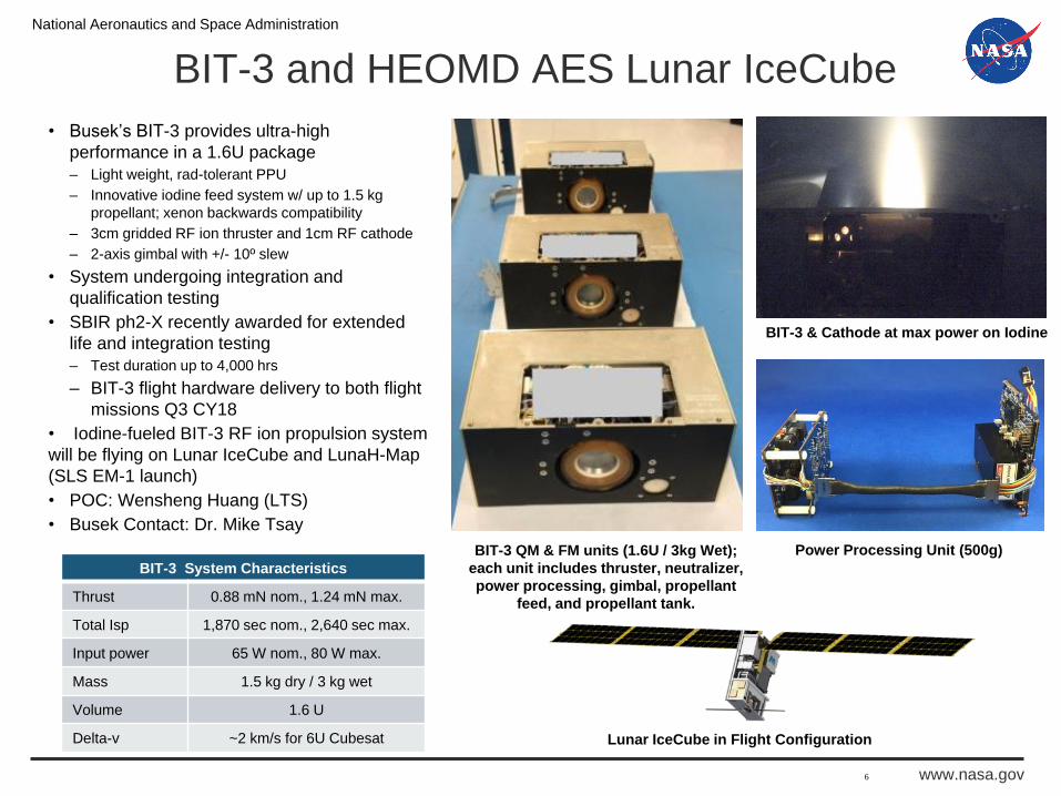
BIT-3 and HEOMD AES Lunar IceCube
• Busek’s BIT-3 provides ultra-high
performance in a 1.6U package
– Light weight, rad-tolerant PPU
– Innovative iodine feed system w/ up to 1.5 kg
propellant; xenon backwards compatibility
– 3cm gridded RF ion thruster and 1cm RF cathode
– 2-axis gimbal with +/- 10º slew
• System undergoing integration and
qualification testing
• SBIR ph2-X recently awarded for extended
life and integration testing
– Test duration up to 4,000 hrs
– BIT-3 flight hardware delivery to both flight
missions Q3 CY18
• Iodine-fueled BIT-3 RF ion propulsion system
will be flying on Lunar IceCube and LunaH-Map
(SLS EM-1 launch)
• POC: Wensheng Huang (LTS)
• Busek Contact: Dr. Mike Tsay
6
Lunar IceCube in Flight Configuration
BIT-3 System Characteristics
Thrust 0.88 mN nom., 1.24 mN max.
Total Isp 1,870 sec nom., 2,640 sec max.
Input power 65 W nom., 80 W max.
Mass 1.5 kg dry / 3 kg wet
Volume 1.6 U
Delta-v ~2 km/s for 6U Cubesat
Power Processing Unit (500g)BIT-3 QM & FM units (1.6U / 3kg Wet);
each unit includes thruster, neutralizer,
power processing, gimbal, propellant
feed, and propellant tank.
BIT-3 & Cathode at max power on Iodine

National Aeronautics and Space Administration
www.nasa.gov 7
Power

National Aeronautics and Space Administration
www.nasa.gov
Advanced ELectrical Bus (ALBus) CubeSat
Mission Objectives
• Demonstration of resettable Shape Memory
Alloy solar array release mechanisms
– Activated Nitinol release mechanism
– Passive superelastic Nitinol hinge springs open
arrays and conduit for solar array power
• On-orbit characterization of high power density
system performance in LEO environment
– Transient distribution of ~100 W of electrical power
in 3U volume
– Passive thermal control
– Characterize and quantify limitations to duty cycle
in changing orbital thermal conditions
• Demonstration of GRC design, 100 W capable
power distribution system
– Battery charging algorithm
– 3.3 V, 5 V and raw battery voltage distribution
GRC’s first fully in-house CubeSat project
Designed, and developed by early career engineers
Pathfinder Technology demonstration for high power
density CubeSats and resettable mechanisms
Set to launch on ELaNa XIX mission

National Aeronautics and Space Administration
www.nasa.gov
Demonstration of a Nano-Enabled
Space Power System
Developing nanomaterial-enhanced power system components that allow for reduced weight
while increasing capability in power systems for cubesats and other small satellites:
• Carbon nanotube (CNT)-enhanced lithium-ion batteries
o Improved power/weight ratio of 301 W-hr/kg
o Demonstrated Low Earth Orbit (LEO) cycling of >1000 cycles with no change in voltage
• Quantum dot/quantum well solar cells with improved efficiency and radiation tolerance
• CNT wire harnesses with reduced weight and increased strength
• CNT thermoelectric materials with improved efficiency of energy harvesting and cooling
• Demonstrate function with high-altitude balloon launch to near space conditions (July 2018)
High-capacity
“pouch” cell
Ryne Raffaelle, Chris Schauerman and Matthew Ganter, Rochester Institute of Technology
Geoffrey A. Landis, NASA Glenn Research Center

National Aeronautics and Space Administration
www.nasa.gov
Development of Lightweight CubeSat with Multifunctional
Structural Battery/Supercapacitor Systems
• Lightweight 1U CubeSat which utilizes fully
integrated structural battery materials for
mission life extension of 200-300%, larger
payload capability, and significantly reduced
mass of 15% or more.
• Mediator-enabled electrolytic polymer Lightweight load bearing structure and an
electrochemical battery system
High specific power and energy with fast charge rate
Significant weight saving
Increase in available volume for payloads
Advancements in structural battery technology can replace parasitic
structural mass with material that provides additional energy, leading
to lighter weigh and extended satellite mission life.
Structural
Supercapacitor

National Aeronautics and Space Administration
www.nasa.gov 11
Communications

National Aeronautics and Space Administration
www.nasa.gov 12
Communications
Candidate Cubesat Mission
Candidate Mission Demonstrations• User initiated service
• SN and NEN services• Commercial service(s)
• Cognitive data routing• Decentralized, service-based• Drop data anywhere
• Link Optimization• Interference mitigation• Spectrum sharing
• Cognitive space hardware• Neuromorphic / memristive• GPU or multi-core processors• Cognitive antenna
Science Node
Processing and Storage Node
LEO<->GEO Comm Node
Non-NASA NetworkTDRS
Ground Station
Inter-satelliteLinks

National Aeronautics and Space Administration
www.nasa.gov
Commercial Ka-band User Terminal Antenna
ExamplesAttributes Functions and Benefits
• Single aperture transmit only or transmit and receive
capability
• Potential for dual-band Ka-band compatibility
(Government 26/22 GHz and commercial 30/20 GHz)
• Electronically scanned beams over at least + 60o field
of regard
• EIRP of 30-36 dBW to enable 10s to 100s M/s via
relays; 100s to 1000s Mb/s via DTG links
• 2-3 types of antennas based on mass, power, volume,
complexity
• Instantaneous electronically steered beams eliminate
vibration and spacecraft disturbances on sensitive
instrumentation
• High rate direct-to-ground (DTG) for latency tolerant
missions and high capacity relay links for latency
sensitive missions
• Dual band (30/26 GHz) enables data return via TDRS
KaSA and/or commercial Ka-band GEO relays, and/or
DTG links
• Helps enable transition to commercially provided
services
Astro Digital Ka-band CubeSat DVB-S2
Transmitter, 21 dBW
Surrey Satellite Ka-band Antenna Positioning
System (APS), e.g. 26cm antenna, >25 dBi,
34 dBW with 8W SSPA
Kymeta Liquid Crystal Ka-band Transmit
Antenna, 23-26 dBi, 32-35 dBW
with 8W SSPA
Proposed Boeing 256-Element Ka-
band Transmit
Phased Array Antenna, 36 dBW
Phasor Solutions Ku-band (14/12 GHz) Flat
PanelAntenna with Potential for Redesign in Ka-band
Spacecraft Body Pointed Mechanically Steered Electronically Steered
Anokiwave 64-Element Ka-band
(27.5-30 GHz) 5G
Wireless Phased Array Antenna

National Aeronautics and Space Administration
www.nasa.gov
Software Defined Radios and Transceivers
ExamplesAttributes Functions and Benefits
• Software defined and re-programmable compatible
with NASA Space Telecommunication Radio System
(STRS) standard
• Adaptive modulation and coding compatible with
CCSDS and DVB-S2 standards MOD/COD family of
waveforms
• Variable data rates from 10s to 100s M/s via relays;
100s to 1000s Mb/s via DTG links
• Low mass/ power/ volume and operational complexity
• High rate direct-to-ground (DTG) for latency tolerant
missions and high capacity relay links for latency
sensitive missions
• Standards compatibility enables waveform sharing
and helps ensure interoperability among commercial
SDR suppliers
• Dual band (30/26 GHz) enables data return via TDRS
KaSA and/or commercial Ka-band GEO relays, and/or
DTG links
• Smart SDRs enable near-optimal use of link margin
Space Micro S-and X/Ka-band
Software-Defined Near-Earth Space Transceiver SBIR
Phase III
JPL ~2 Gb/s Near Earth Ka-band Modulator for
Universal Space Transceiver
Harris
AppSTAR™ 3rd
Generation Micro
Space Software
Defined Platform
for ~1 Gb/s Coded
Modulation
Harris
AppSTAR™ Micro
3rd Generation
SDR and Ka-band
RF Assemblies
Operational Under Development
Tethers
Unlimited
OpenSWIFT-
SDR for STRS
SBIR Phase II

National Aeronautics and Space Administration
www.nasa.gov 15
Instruments

Compact Full-Field Ion Detector System
(CFIDS) Concept
Type of Sensor: Low-power, spherical space
radiation detector system prototype for CubeSat-
based cosmic ray charged-particle spectrometry
Performance Parameters/Metrics:
• Simultaneous measurements of protons and
heavy ions from moderate to relativistic
energies (250 keV/u — 3 GeV/u) from 12
different directions for broad science charged
particle investigations
• Each detector pair 0.09 cm²·sr and a 25° field
of view
Proposed Applications:
• Improve measurements of galactic
cosmic ray (GCR) high Z and energy
(HZE) ion ratios to better understand
intragalactic ion propagation
• Study of the impact of GCR HZE ions
on planetary magnetospheres,
atmospheres, and space weathering
• Understand how variations of GCR
ions influence solar effects on
planetary atmospheric composition
and climate
Approach w/Milestones & Timeline:
• Develop novel temperature-
insensitive detectors based on wide-
band-gap semiconductors (SiC, ZnO,
GaP) to allow compact design
• 3-year approach from component
prototypes, through system
integration, to engineering unit
demonstration16

Solar Proton Anisotropy and Galactic Cosmic Ray High
Energy Transport Instrument (SPAGHETI) Concept
Type of Sensor: Charged-particle spectrometer
integrated on a Deep Space 6U CubeSat using 6
pair of Linear Energy Transfer (LET) detectors
made of SiC to be more robust than silicon-based
detectors and immune to temperature effects.
Performance Parameters/Metrics:
• Multidirectional measurements of protons &
heavy ions from moderate to high energy
(250 keV/u - 300 MeV/u) to observe ion flux
anisotropy in GCR & SPEs on 0.1-1 Hz scale
for specific charged particle science
objectives
• Each axis (±X, ±Y, ±Z) would have a 80° field
of view and a 0.84 cm²·sr geometric factor
Proposed Application:
• Measure anisotropic variability
of SPE and GCR ions in deep
space and Lunar orbit
• Understand how these
variations impact space
radiation environment,
interplanetary radiation
transport, and Lunar surface
albedo radiation
Approach w/Milestones & Timeline:
• Proposed as part of a 6U CubeSat
flight mission to Lunar orbit from EM-1
deployment using an iodine ion
thruster
• 3-year effort from prototype
development of SiC LET detectors to
beam line tests
17
Detector stack containing SiC
LET detectors.
SPAGHETI
CubeSat

National Aeronautics and Space Administration
www.nasa.gov
One ~1500 hr day
Landed Operations
One ~1500 hr Night
Gas/Pressure/Temp/
Wind Speed
Direction 2 minutes
of samples every 12
hrs
2 min UHF, 36 bps
Uplink to Orbiter 3
times a day
Daytime operations
at same level as
daytime except
without IR
bolometers
Orbiter in
highly elliptic,
240hr orbit
Gas/Pressure/Temp
/Wind Speed
Direction 2
minutes of samples
every 12 hrs
IR Bolometers
probe the
atmosphere 2
minutes of
samples every
12 hrs
Orbiter IR
imager images
Venus twice an
orbit at the
same time as
the lander
V-BOSS: Venus Bridge Orbiter and Surface System
ConceptG. Hunter, V-BOSS: Venus Bridge Orbiter and Surface System, Preliminary Report,
https://www.lpi.usra.edu/vexag/meetings/archive/vexag_15/presentations/21-COMPASS-Venus-
Bridge-Summary.pdf
18
National Aeronautics and Space Administration
www.nasa.gov 19
Gabriel F. Benavides, Hani Kamhawi, Geoffrey
A. Landis, Thomas B. Miller, Dale J. Mortensen,
Kathryn J. Oriti, Charles J. Sarmiento,
Wensheng Huang, John D. Wrbanek, Sue
Wrbanek, Steven Oleson, J. Michael Newman
NASA Glenn Research Center,
Cleveland, OH
Luke B. Roberson NASA Kennedy Space Center,
Titusville, FL
Larry Byrne, Dr. Mike Tsay Busek Co., Inc., Natick, MA
Ryne Raffaelle, Chris Schauerman, Matthew
Ganter
Rochester Institute of Technology,
Rochester, NY
Mason Freedman, Karsten James Tethers Unlimited, Inc, Bothell, WA
Xiangyang Zhou, Ryan Karkkainen University of Miami, Coral Gables, FL
Acknowledgements