Embed Size (px)
Citation preview
Overview of Task 1
GE Energy Coupled Microgrid Project - University of Notre Dame - April 19, 2012
Objective: Maximize real power exported to mid-voltage distribution networks from coupled low-voltage microgrids.
Issues:- Voltage-rise problem;
Weak network property;Legacy control’s compatibility.
- -
Approach:- Reactive power dispatch;
Simulation analysis.-
Benefits:- Minimize impact on existing
voltage regulation policies;Maximize real power exported back to distribution network.
- - Distributed optimal controller;
OLTC
microgrid microgrid microgrid
SVCSTATCOM
Distribution Network with Legacy ControlsFig. 1
Task 1.1 Algorithm Development
GE Energy Coupled Microgrid Project - University of Notre Dame - April 19, 2012
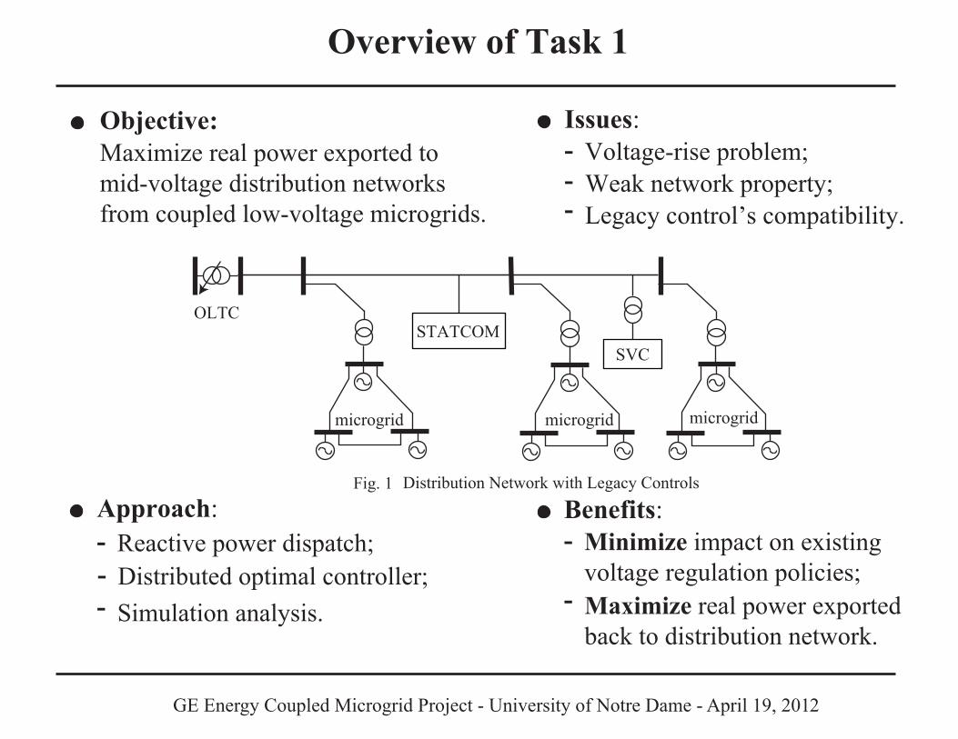
Objective Manage generations coordinatively to export maximum real power and maintain voltage levels within limits.
A hierarchical control architecture includes: Microgrid Consortium Manager (MCM), Microgrid Interface Controller (MIC), and CERTS droop controller. Two levels of optimization problems in MICs: microgrid states are determined locally; set points of microsources are solved in a centralized manner.
Results
OLTC
microgrid microgrid microgrid
MCM
MIC MIC MIC
STATCOMSVC
-
-
Hierarchical Control ArchitectureFig. 2
GE Energy Coupled Microgrid Project - University of Notre Dame - April 19, 2012
Task 1.2 Simulation Development
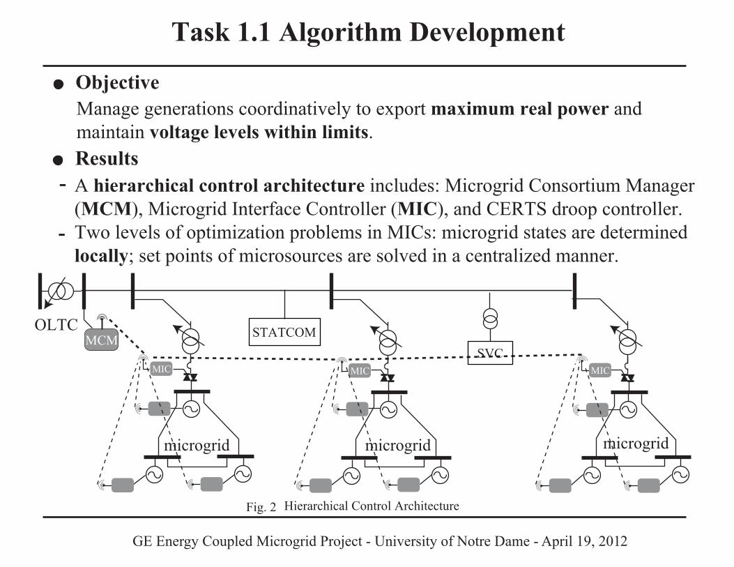
Objective & Approach Performance of the proposed controller is checked in distribution network simulation models. Simulations are built with simpower toolbox in matlab.
A complete simulation model of distribution network is formulated, including the proposed hierarchical control architecture.Legacy control devices are individually integrated into the simulation model to check controller compatibility.
Result -
-
V_mcm
cap_mic
trig_ln1
trig_ln2
S_ln1
S_ln2
change_mic
P_opt_mic
Q_opt_mic
V_mag
V_pha
recal_mg1
P_mg
Q_mg
V_mag
V_pha
switch_mg
P_opt1
P_opt2
P_opt3
V_req1
V_req2
V_req3
Microgrid Capacity Estimation
Microgrid Operate PointDetermination
MicrosourceSet Points Determination
Realization of MIC in the Simulation ModelFig. 3
StructuralInformation
State of Neighbors
Microgrid Set Point
Set Points ofMicrosourcesStructural
InformationStructuralInformation
GE Energy Coupled Microgrid Project - University of Notre Dame - April 19, 2012
Task 1.3 Evaluation
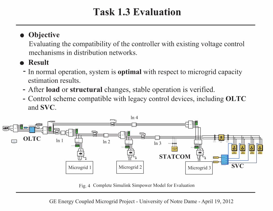
Objective Evaluating the compatibility of the controller with existing voltage control mechanisms in distribution networks.
In normal operation, system is optimal with respect to microgrid capacity estimation results.After load or structural changes, stable operation is verified. Control scheme compatible with legacy control devices, including OLTCand SVC.
Result -
-
OLTC
STATCOM
Complete Simulink Simpower Model for EvaluationFig. 4
-
powergui
Discrete,Ts = 5e-005 s.
mg3_scopemg2_scope
mg1_scope
Vab
cIa
bcP
QR
MS
( V-I)
A B C
a b cVa b
cIa
bcP
QR
MS
( V-I)
A B C
a b cVabcIabcPQ
RMS (V-I)
A
B
C
abc
VabcIabcPQ
RMS (V-I)
A
B
C
abc
Vab
cIa
bcP
QR
MS
( V-I)
A B C
a b c
VabcIabcPQ
RMS (V-I)
A
B
C
abc
VabcIabcPQ
RMS (V-I)
A
B
C
abc
VabcIabcPQ
RMS (V-I)
A
B
C
abc
grid_scope
A*
B*
C** * *
cable_S3_to_S4
ABC
A*B*C*
A*
B*
C*
cable_S2_to_S3
ABC
A*B*C*
cable_S1_to_S4
ABC
A*B*C*
cable_S1_to_S2
ABC
A*B*C*
VabcVabcB2
Three-Phase OLTCRegulating Transformer2
Vm (pu) Tap
A
B
C
a
b
ccom
ABC
abc
comABC
abc
comABC
abc
comABC
abc
Tap1
T4
A B C
a b c n2
T3
A B C
a b c n2
T2
A B C
a b c n2
Substation
A
B
C
S4_scope
S3_scope
S2_scope
S1_scope
Tap1
[S_ln2]
[S_ln1]
[V1_B1]
[S_ln4]
[S_ln3]
Microgrid 1 Microgrid 2 Microgrid 3
TSC194 Mvar
TCR109 Mvar
TSC294 Mvar
TSC394 MVar
P A B CP A B CP A B CP A B C
Secondary
(480 V)
A
B
C
a
b
c
SVC Controller
Vabc_prim
Vabc_sec
TCR
TSC1
TSC2
TSC3
Primary
(13.8 kV)
A
B
C
a
b
c
Vabc_Prim
Vabc_Sec
13.8 kV/480 V
1 MVA
A
B
C
a
b
c
SVCA B C
D-STATCOM+/- 3Mvar
Bstatcom A B C
a b c
ln 1 ln 2 ln 3
ln 4
GE Energy Coupled Microgrid Project - University of Notre Dame - April 19, 2012
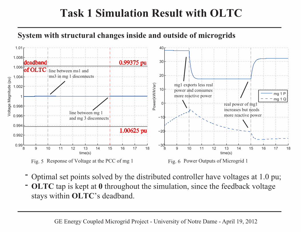
Task 1 Simulation Result with OLTC System with structural changes inside and outside of microgrids
Response of Voltage at the PCC of mg 1Fig. 5
- -
Power Outputs of Microgrid 1Fig. 6
Optimal set points solved by the distributed controller have voltages at 1.0 pu;OLTC tap is kept at 0 throughout the simulation, since the feedback voltage stays within OLTC’s deadband.
line between mg 1 and mg 3 disconnects
line between ms1 and ms3 in mg 1 disconnects
mg1 exports less realpower and consumes more reactive power
real power of mg1 increases but needs more reactive power
1.00625 pu
8 9 10 11 12 13 14 15 16 17 180.99
0.992
0.994
0.996
0.998
1
1.002
1.004
1.006
1.008
1.01
time(s)
Vol
tage
Mag
nitu
de (p
u)
deadbandof OLTC
0.99375 pu
8 9 10 11 12 13 14 15 16 17 18−30
−20
−10
0
10
20
30
40
time(s)P
ower
(kW
/kV
ar)
mg 1 Pmg 1 Q
GE Energy Coupled Microgrid Project - University of Notre Dame - April 19, 2012
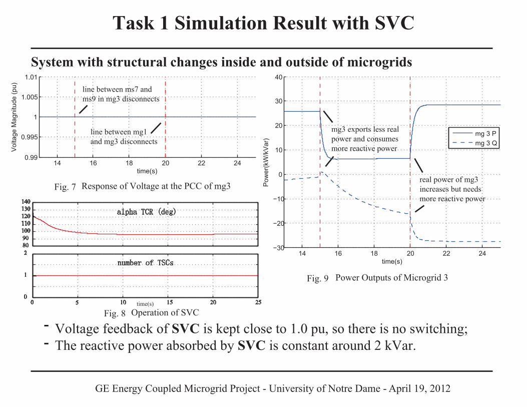
Task 1 Simulation Result with SVC System with structural changes inside and outside of microgrids
Response of Voltage at the PCC of mg3Fig. 7
- -
Power Outputs of Microgrid 3Fig. 9
Voltage feedback of SVC is kept close to 1.0 pu, so there is no switching;The reactive power absorbed by SVC is constant around 2 kVar.
line between mg1 and mg3 disconnects
line between ms7 and ms9 in mg3 disconnects
mg3 exports less realpower and consumes more reactive power
real power of mg3 increases but needs more reactive power
14 16 18 20 22 240.99
0.995
1
1.005
1.01
time(s)
Vol
tage
Mag
nitu
de (p
u)
14 16 18 20 22 24−30
−20
−10
0
10
20
30
40
time(s)P
ower
(kW
/kV
ar)
mg 3 Pmg 3 Q
0 5 10 15 20 250
1
2
number of TSCs
8090100110120130140
alpha TCR (deg)
Operation of SVCFig. 8 time(s)
GE Energy Coupled Microgrid Project - University of Notre Dame - April 19, 2012
Task 1 Conclusion
The hierarchical controller proposed does not interfere with legacyvoltage control devices, such as OLTC and SVC.
-
-
-
During structural changes inside and outside of microgrids, the operation of legacy control devices is not influenced by microgrids;
Distributed optimal controller reconfigures coupled microgrids to exportmaximum real power and maintain PCC voltages close to 1.0 pu;
Proposed controller is realizable in microgrid controllers from GE, and itwill not interfere with existing distribution network control mechanisms.
If cooperation with DSO is available, voltage control devices beingset according to the connected microgrids, then at least 20% more real power is expected to be provided by coupled microgrids.
GE Energy Coupled Microgrid Project - University of Notre Dame - April 19, 2012
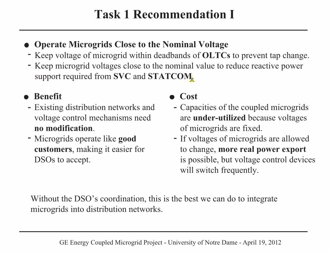
Task 1 Recommendation I
Operate Microgrids Close to the Nominal Voltage Keep voltage of microgrid within deadbands of OLTCs to prevent tap change.Keep microgrid voltages close to the nominal value to reduce reactive power support required from SVC and STATCOM.
- -
BenefitExisting distribution networks and voltage control mechanisms need no modification. Microgrids operate like good customers, making it easier for DSOs to accept.
-
-
CostCapacities of the coupled microgridsare under-utilized because voltagesof microgrids are fixed. If voltages of microgrids are allowedto change, more real power export is possible, but voltage control deviceswill switch frequently.
-
-
Without the DSO’s coordination, this is the best we can do to integrate microgrids into distribution networks.
GE Energy Coupled Microgrid Project - University of Notre Dame - April 19, 2012
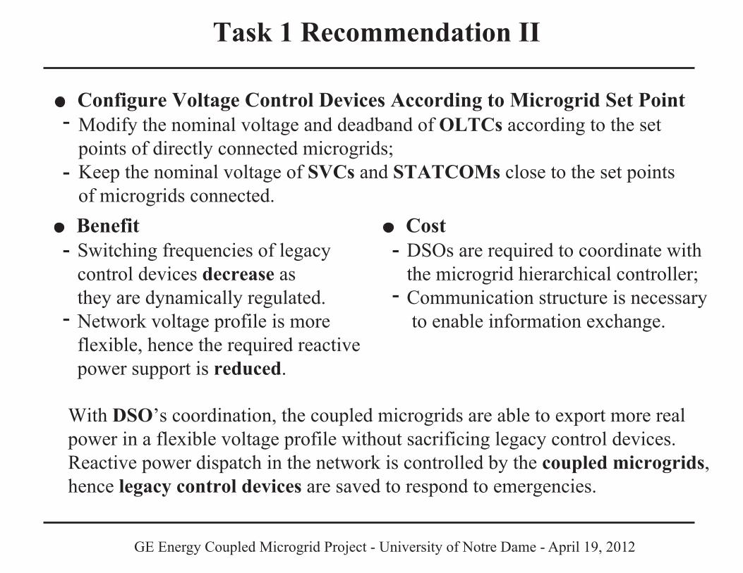
Task 1 Recommendation II
Configure Voltage Control Devices According to Microgrid Set Point Modify the nominal voltage and deadband of OLTCs according to the set points of directly connected microgrids;Keep the nominal voltage of SVCs and STATCOMs close to the set points of microgrids connected.
-
-
BenefitSwitching frequencies of legacy control devices decrease as they are dynamically regulated. Network voltage profile is more flexible, hence the required reactive power support is reduced.
-
-
CostDSOs are required to coordinate withthe microgrid hierarchical controller;Communication structure is necessary to enable information exchange.
-
-
With DSO’s coordination, the coupled microgrids are able to export more real power in a flexible voltage profile without sacrificing legacy control devices. Reactive power dispatch in the network is controlled by the coupled microgrids,hence legacy control devices are saved to respond to emergencies.