Embed Size (px)
Citation preview

OVERVIEW OF THE REINFORCED EARTH STRUCTURES FOR BERMONDSEY DIVE UNDERIGS UK Symposium: Use of Geosynthetics in Rail: Towards 2025

BERMONDSEY DIVE UNDER
National Rail map
• North-South between Bedford and Brighton
• Serving Gatwick and Luton airports
• 12 car capacity and 24 train paths per hour through the “Central Core”.
Bermondsey
THAMESLINK

BERMONDSEY DIVE UNDERA KEY COMPONENT OF THE FINAL STAGE OF THE THAMESLINK PROGRAMME AND THE REBUILDING OF LONDON BRIDGE STATION.
Untangling of the existing tracks over a 1.4 km section through Bermondsey
BERMONDSEY DIVE UNDER
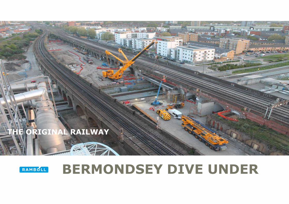
THE ORIGINAL RAILWAY

BOLINA ROAD BEFORE CONSTRUCTION
BERMONDSEY DIVE UNDER

JANUARY 2017
BERMONDSEY DIVE UNDER GROUND ENGINEERING AWARDS 2017
LAYOUT OF THE STRUCTURES
Western Flyover Ramp
Western Dive Under Ramp Pre-cast Arches supported on existing arch foundations
Western Dive Under Ramp Reinforced Earth Walls
Dive Under Box and Earthworks
Bolina Road Structures
BERMONDSEY DIVE UNDER

JANUARY 2017
BERMONDSEY DIVE UNDER GROUND ENGINEERING AWARDS 2017
LAYOUT OF THE STRUCTURES
Eastern Ramp Reinforced Earth
Eastern Ramp Pre-cast Arches
Steel Composite Structure
Embankment
BERMONDSEY DIVE UNDER

BERMONDSEY DIVE UNDERGRIP 4 DESIGN OF THE REINFORCED EARTH STRUCTURES

BERMONDSEY DIVE UNDERGRIP 4 DESIGN OF THE REINFORCED EARTH STRUCTURES
The main concept was for a
reinforced earth wall
supported on a piled load
transfer platform

BERMONDSEY DIVE UNDER
Area to be filled within the Box
GRIP 4 DESIGN OF THE REINFORCED EARTH STRUCTURES
“Bridge” Pier
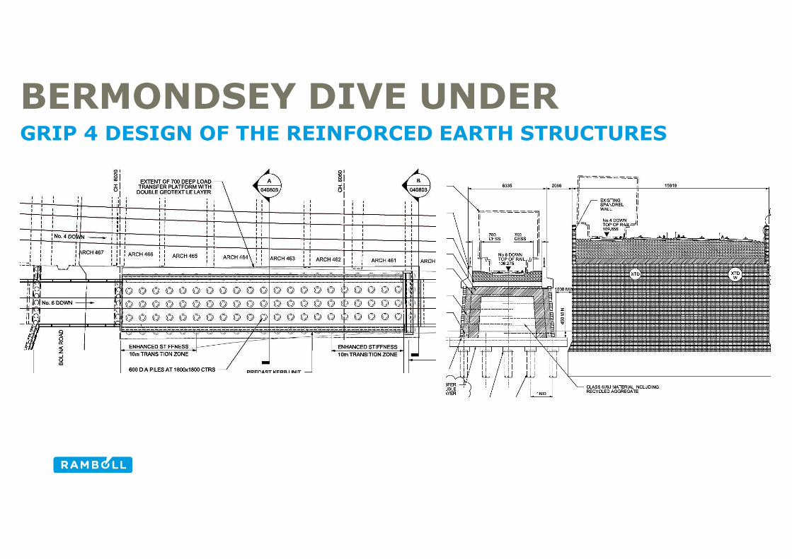
GRIP 4 DESIGN OF THE REINFORCED EARTH STRUCTURES
BERMONDSEY DIVE UNDER
BERMONDSEY DIVE UNDER
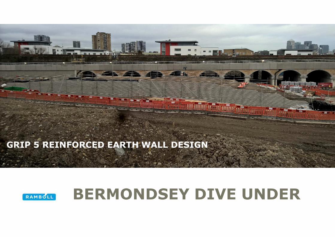
GRIP 5 REINFORCED EARTH WALL DESIGN
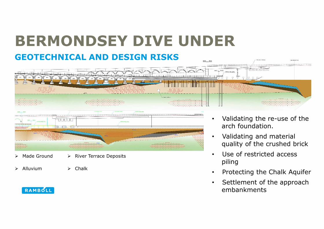
GRIP STAGE 5 DESIGNBERMONDSEY DIVE UNDERGEOTECHNICAL AND DESIGN RISKS
• Validating the re-use of the arch foundation.
• Validating and material quality of the crushed brick
• Use of restricted access piling
• Protecting the Chalk Aquifer
• Settlement of the approach embankments
� Made Ground
� Alluvium
� River Terrace Deposits
� Chalk

GRIP STAGE 5 DESIGNBERMONDSEY DIVE UNDERGRIP 5 REINFORCED EARTH WALL DESIGN

BERMONDSEY DIVE UNDERGRIP 5 REINFORCED EARTH WALL DESIGN
Geo-grid Reinforcement
Modular Block Reinforced Wall
Derailment Wall
Drainage
Derailment Wall
Modular Block Reinforced Wall
DrainageRC deck near above existing ground level

GRIP STAGE 5 DESIGNBERMONDSEY DIVE UNDERGRIP 5 REINFORCED EARTH WALL DESIGN
Method of analysis:
• Ultimate Limit State Design – BS8006:2010
• Serviceability Limit State – Plaxis 2D FE
Typical Loading Conditions:
• Rail Live Load – 50 kPa
• Walkways – 5 kPa
• Abnormal Rail Loading - KIROW KRC1200 UK rail mounted crane operating as a crane

GRIP STAGE 5 DESIGNBERMONDSEY DIVE UNDERGRIP 5 REINFORCED EARTH WALL DESIGN
Plaxis Models:
Model 1 – Reinforced earth ‘back to back’ wall system
Model 2 – Typical embankment with good granular fill material (same properties as reinforced earth)
Model 3 – Typical embankment with poor granular fill material

GRIP STAGE 5 DESIGNBERMONDSEY DIVE UNDERGRIP 5 REINFORCED EARTH WALL DESIGN
Layer Unit Weight, γ
(kN/m3)
Cohesion, c
(kN/m2)
Angle of Internal Friction, φ
(degrees)
Young’s Modulus, E
(kN/m2)
Ballast 21 0.1 35 60000
Reinforced Earth Fill 20 0.1 35 50000
Good granular Fill 20 0.1 35 50000
Embankment Fill 20 0.1 30 25000
Analysis Assumptions:• All wall elements are fixed connections• The base of the reinforced earth wall facing is fixed to the reinforced concrete
slab at the base of the model therefore there is no lateral or rotational movement at this point
• The parameters of the crushed brick fill for the reinforced earth are the same as those from the Bermondsey Dive Under structure Form A documents
• Fill material properties

GRIP STAGE 5 DESIGNBERMONDSEY DIVE UNDERGRIP 5 REINFORCED EARTH WALL DESIGN

GRIP STAGE 5 DESIGNBERMONDSEY DIVE UNDERGRIP 5 REINFORCED EARTH WALL DESIGN

GRIP STAGE 5 DESIGNBERMONDSEY DIVE UNDERGRIP 5 REINFORCED EARTH WALL DESIGN

GRIP STAGE 5 DESIGNBERMONDSEY DIVE UNDERGRIP 5 REINFORCED EARTH WALL DESIGN
Model Maximum Lateral Movement of Wall
Element or within Embankment (mm)
Maximum Vertical
Displacement (mm)
Model 1 0.6 (wall) 3.2
Model 2 0.9 (embankment) 4.4
Model 3 1.5 (embankment) 5.6
Summary of the Plaxis results

BERMONDSEY DIVE UNDER
USE OF THE DEMOLISHED BRICK FROM THE ARCHES

GRIP STAGE 5 DESIGNBERMONDSEY DIVE UNDERUSE OF THE DEMOLISHED BRICK FROM THE ARCHES
Risks
• Crushing of the bricks not providing a Class 6I/6J fill
• Long-term durability
Mitigation
• Materials Management Plan• Materials Engineer on site• Use as an alternative material
where not compliant as a 6I/6J fill e.g. working platforms

GRIP STAGE 5 DESIGNBERMONDSEY DIVE UNDERUSE OF THE DEMOLISHED BRICK FROM THE ARCHES
Preliminary Testing of the Crushed Brick
• Crushing of the bricks not providing a Class 6I/6J fill
• Long-term durability
Mitigation
• Materials Management Plan• Materials Engineer on site• Use as an alternative material
where not compliant as a 6I/6J fill e.g. working platforms

BERMONDSEY DIVE UNDERSUSTAINABLE INFRASTRUCTURE DELIVERY
Environmental Benefits • Reduced impact on local
traffic• Reduced consumption of
steel and concrete• Reduced carbon emissions• Reduced risk to the
contaminating groundwater
• Reduced waste by using
off-site pre-cast concrete• Reduced programme time
and delays to passengers
Economic Efficiencies • Removed around 40% of the
piles from the scheme • Reduced pile lengths through
preliminary pile testing• Reduced excavations and
material disposal• Limit the amount of material for
and re-use of working platform materials
• Re-use of the brick from the demolished arches and other recycled materials where possible
• Reduced programme
SocialBenefits • Structures sympathetic to the
existing viaducts which are some of the oldest in London
• Enhancement of the existing arches and allow Network Rail to rent them out for business use
• Will improve the experience of rail travel across the capital for thousands of people every day.
• Enables increased passenger capacity
• The site has now been cleaned up and rejuvenated to provide a vastly improved environment for local residents to enjoyEconomic Environmental
Social

BERMONDSEY DIVE UNDERSUSTAINABLE INFRASTRUCTURE DELIVERY
BOLINA ROAD AFTER CONSTRUCTION

THANK YOU