Embed Size (px)
Citation preview

Overview of WC-130J storm-scale Overview of WC-130J storm-scale observations during TPARC/TCS08observations during TPARC/TCS08
Peter G. Black (1) and Jeffrey D. Hawkins (2)
(1) SAIC, Inc. and Naval Research Laboratory, Monterey, CA(2) Naval Research Laboratory, Monterey, CA
Third THORPEX International Science SymposiumThird THORPEX International Science SymposiumMonterey, CAMonterey, CA14-18 September, 200914-18 September, 2009
TCS08 Experiment Analysis: TCS08 Experiment Analysis: Tools
1) WC-130J Aircraft (2)• GPS dropsonde (750, ~ 26/flt) for
atmospheric profiling (high-altitude)• AXBT*- ocean thermal profiling (250, ~ 13/flt)• SFMR- surface winds• Radar Video Recording*- TC structure• ADOS profiler/ Minimet drift buoys- 3D ocean
structure, surface currents (24)2) NRL P3 (1)
• Eldora Doppler Radar- 3D winds• LIDAR*- boundary layer wind profiles• GPS dropsonde- atmospheric profiling (low)
*First used in TCS08
What did we use?

TCS08 Experimental Analysis: TCS08 Experimental Analysis: Statistics
Research Flights• Missions: 26• Mission Flight Hours: 263• High-Level Missions, 300mb: 12• TC 700mb Missions: 12• Buoy Deployment Missions: 2• Tropical Cyclones: 4
WC-130J Aircraft Performance

TC Observational StrategyTC Observational Strategy
• Define vertical structure over a TC Define vertical structure over a TC vortex-scale domain (WC-130J) in vortex-scale domain (WC-130J) in developing/intensifying systems within developing/intensifying systems within environmental domain (SAT, DOTSTAR, environmental domain (SAT, DOTSTAR, FALCON) to provide context for FALCON) to provide context for mesovortex (VHT) domain (P3)mesovortex (VHT) domain (P3)
• Focus on better definition of Focus on better definition of asymmetric 3D initial vortex in sheared asymmetric 3D initial vortex in sheared environment for evolving coupled environment for evolving coupled modelsmodels
• Driven by emerging requirements for Driven by emerging requirements for improved 5 to 7 day forecasts improved 5 to 7 day forecasts

Unprecidented Real-Time Unprecidented Real-Time Satellite Capabilities: Data FusionSatellite Capabilities: Data Fusion

TCS08 Experiment Analysis:TCS08 Experiment Analysis:Situational AwarenessSituational Awareness
Real-Time Communications
Real-Time Data Fusion
TCS08 Experiment Analysis:TCS08 Experiment Analysis: HYPOTHESES I
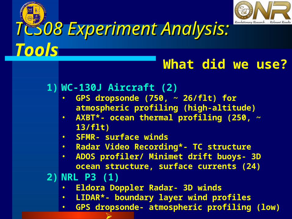
First of Two Key Hypotheses:I. Typhoon Formation emerges from initial
meso-vortex in Convective Cloud Clusters via: • Mid-level spin-up and downward growth,
i.e.-
Top-Down
OR
• Low-level spin-up and upward growth, i.e.-
Bottom-Up

TCS08 Experiment Analysis: TCS08 Experiment Analysis: Scenarios
Two of severalKey Formation Scenarios:
• Tropical Easterly Wave/ Upper Trough Interactions: (Many observed during TCS08)
• Westerly Wind Burst associated withmonsoon trough: (NONE observed during
TCS08)

TCS08 Experiment Analysis: TCS08 Experiment Analysis: RATIONALE I I
I.I. New 5-day forecasts (soon 7-day forecasts) New 5-day forecasts (soon 7-day forecasts) require improved knowledge of TC Formation:require improved knowledge of TC Formation:
• Where? Where? • How Fast?How Fast?
II.II. Strategic and economic consequences Strategic and economic consequences increasing exponentially with time! increasing exponentially with time!
Why Investigate TC Formation?

TCS08 Experiment Analysis: TCS08 Experiment Analysis: OBJECTIVE I
1) Address Hypothesis I: Develophigh-level WC-130J Aircraft observingstrategy to define:
• TC 3D storm-scale structure • Intensity Change • Context for NRL P3 meso-scale obs

TCS08 Experiment Analysis: TCS08 Experiment Analysis: RESULTS I
1) Hypothesis I: Concurrent low- and mid-levelvortices were observed in developing
andnon-developing TC Formation caseswith 120 – 200 km separation (In TropicalWave/ TUTT interaction cases), i.e. not
singletilted vortex, but distinct vortex pairs
(Preliminary)
Challenge is to learn to distinguish developers from non-developers

x
Surface
700 mb
120 km
TCS-2527-28, Aug
Surface
15 kt
15 kt
x
TCS-2527-28, Aug
700 mb
20 kt
20 kt
x
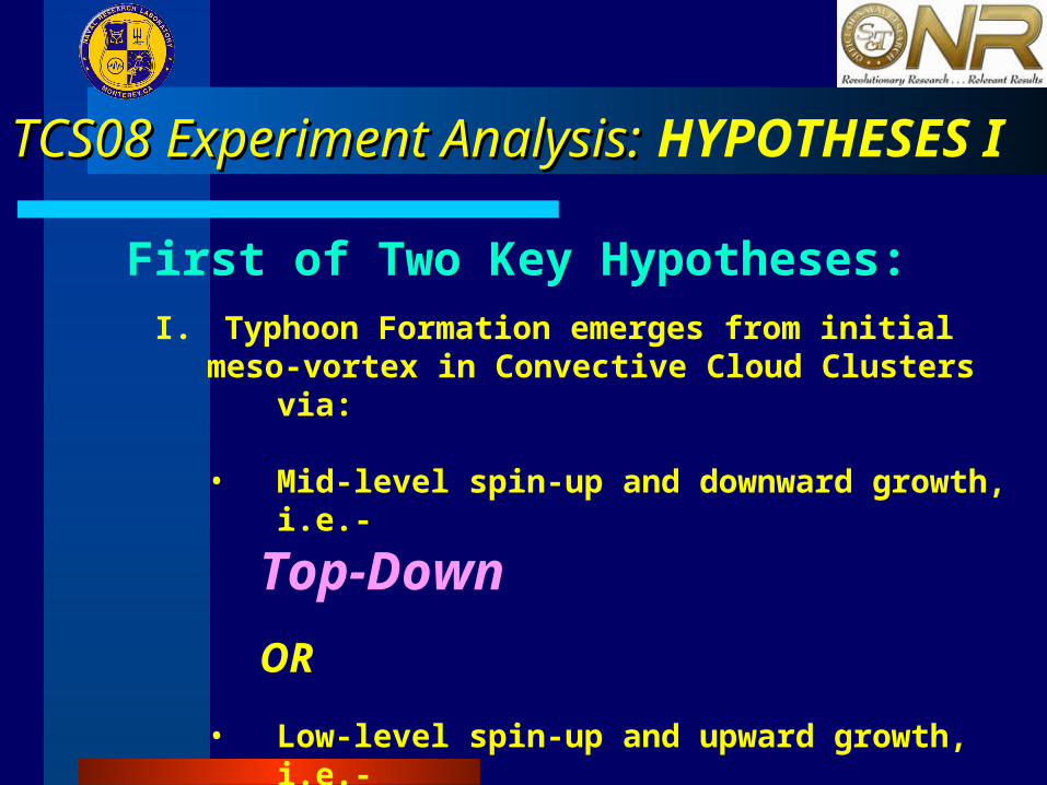
SSMIS- F1627 Sept, 2213 GMTWC-130J sondes- SFC27 Sept, 21 UTC -28 Sept, 03 UTC

TCS-37Surface
200 km separation
15 kt
25 kt
15 kt
25 kt
TCS-37400 MB

0030 UTC7 Sept, 2008
TCS-37
Data Fusion:Google-EarthEnhanced IR +WC-130J flight track, Dropsonde locations
Active convectionAt begining of flight
0330 UTC7 Sept, 2008
Convection collapsesnear end of flight

TCS08 Experiment AnalysisTCS08 Experiment Analysis: : HYPOTHESES II
Second of Two Key Hypotheses:
II. Typhoon Intensity Change, including RapidIntensification (RI), is driven by atmosphericconditioning:
• Large-scale environmental interaction
• Oceanic Variability
TCS08 Experiment Analysis: TCS08 Experiment Analysis: RATIONALE IIRATIONALE II
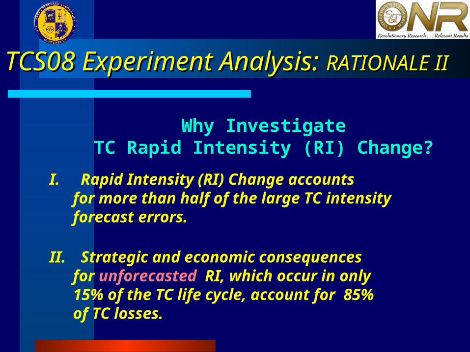
I. Rapid Intensity (RI) Change accounts for more than half of the large TC intensity forecast errors.
II. Strategic and economic consequences for unforecasted RI, which occur in only 15% of the TC life cycle, account for 85% of TC losses.
Why InvestigateTC Rapid Intensity (RI) Change?

TCS08 Experiment Analysis: TCS08 Experiment Analysis: OBJECTIVE II
2) Address Hypothesis II: Develop TCand ocean observing strategy to definebackground ocean conditions andocean-TC interaction
(Environmental monitoring accomplished by TPARClarge-scale observing strategy)
TCS08 Experiment Analysis: TCS08 Experiment Analysis: RESULTS II
2) Hypothesis II: Rapid TC Intensificationand Rapid TC Filling occurred over Warmand Cold eddies, respectively, in the WPACSouthern Eddy Zone*
Defined by Wu, et al. (18-25N)
(Preliminary)

SATCON Intensity:Velden, CIMSSHawkins, NRL
TCS08Jangmi Sept, 2008Track,Intensity Change
Aircraft
JMA
9/23 9/24 9/25 9/26 9/27 9/28 9/29 9/30 10/1 10/2
920
900
940
960
980
1000
Pre
ssu
re (
mb
)
0
50
100
150
Win
d S
pee
d (
kt)
Rap
id
Inten
sification
RapidFilling
Aircraft Pmin
OH
C G
rad
ien
t
LandfallK
uro
sh
io
Rapid Structure Change
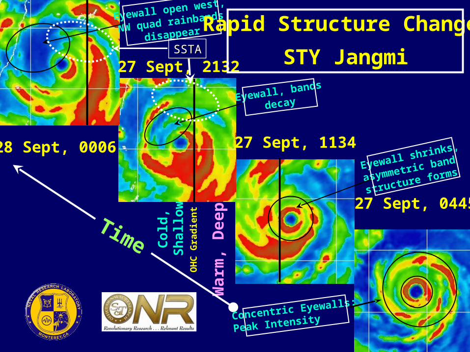
27 Sept, 1134
27 Sept, 2132
28 Sept, 0006
OH
C G
rad
ien
t
Col
d,
Sh
allo
w
War
m, D
eep
Eyewall, bands
decay
Eyewall shrinks,
asymmetric band
structure forms
Eyewall open west,
NW quad rainbands
disappear
27 Sept, 0445
STY Jangmi
Rapid Structure Change
Time
Concentric Eyewalls:
Peak Intensity
SSTASSTA

JangmiJangmiSSTASSTA20082008
26 Aug26 Aug
JangmiJangmiSSTASSTA20082008
28 Aug28 Aug
JangmiJangmiOHCOHC
27 Aug27 Aug
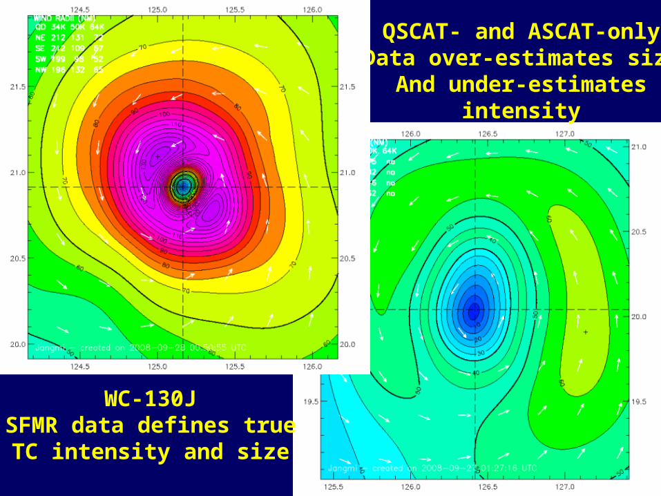
QSCAT- and ASCAT-onlyData over-estimates size
And under-estimatesintensity
WC-130JSFMR data defines true
TC intensity and size

Super-TyphoonJangmi
27 Sept., 20080935 UTC
Radar Video definesEyewall and Rainband Structure and Evolution
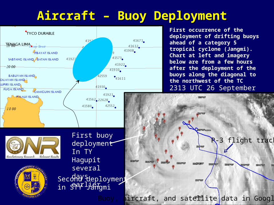
Aircraft – Buoy DeploymentAircraft – Buoy Deployment
P-3 flight track
2313 UTC 26 September
First buoy deploymentIn TY Hagupit several days earlier
Second deploymentin STY Jangmi
Buoy, aircraft, and satellite data in Google Earth
First occurrence of the deployment of drifting buoys ahead of a category 5 tropical cyclone (Jangmi). Chart at left and imagery below are from a few hours after the deployment of the buoys along the diagonal to the northwest of the TC

TCS08 AXBT LocationsKo, NRL Stennis
AXBT vs NRL OceanModel Initial Conditions
TCS08 Ocean HeatContent Obs: •Concurrent with GPS dropsondes•Preview of ITOP2010
Modelunderpredictshigh heatcontent
Ocean Heat Content (OHC)
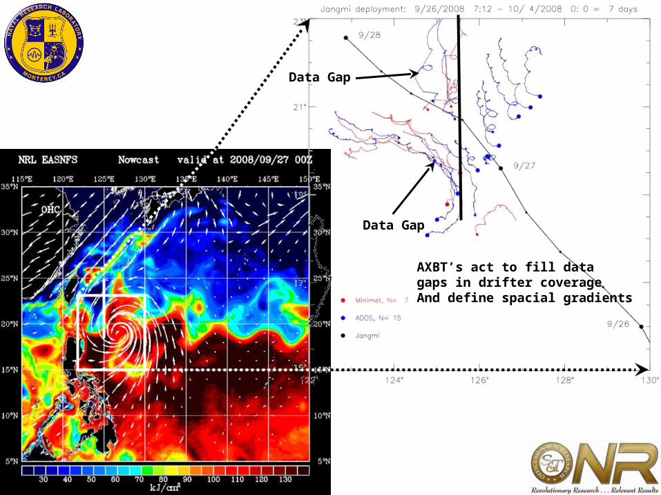
Data Gap
Data Gap
AXBT’s act to fill datagaps in drifter coverageAnd define spacial gradients

2008 Drifters2008 Drifters
25 Aug25 Aug 27 Aug27 Aug 29 Aug29 Aug
Ko, NRL Stennis
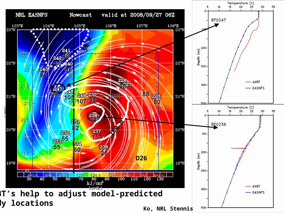
AXBT’s help to adjust model-predictededdy locations
D26
100
m
50 m
FINAL COMMENT
• We are at an historic turning point in history for improving hurricane intensity observation and forecasting where the capability to observe the TC surface and mid-level wind domain concurrent with subsurface ocean thermal structure matches the improved coupled model capabilities to assimilate and model the total TC environment.
• This alignment should provide the next best opportunity for improving hurricane intensity and structure forecasting.

CONCLUSIONSCONCLUSIONS
1. ‘Tip-of-the-iceberg’ Results:
• Co-existence of low/mid level vortex pairs is typical of formation events• Strong relation of RI/RF to warm/cold ocean eddies in absence of strong
atmospheric forcing• The observation strategy for TCS08 was sound
2. ‘Stage is set’ for additional in-depth analysis
• Determine system evolution with time• Validate satellite estimation schemes• Elaborate theoretical hypotheses leading to new physics• Conduct coupled numerical model simulations to test new physics
3. For the Future- Fill GAPS (possibly in concert with ITOP 2010) by observing:
• Normally-dominant monsoon trough/ westerly burst formation events• Vortex-pair TC formation scenarios• Satellite validation cases to reach statistical significance• Air-sea RI events with and without strong shear for small/large TCs

END

Overview of WC-130J storm-scale Overview of WC-130J storm-scale observations during TPARC/TCS08observations during TPARC/TCS08
Peter G. Black (1) and Jeffrey D. Hawkins (2)
(1) SAIC, Inc. and Naval Research Laboratory, Monterey, CA(2) Naval Research Laboratory, Monterey, CA
Third THORPEX International Science SymposiumThird THORPEX International Science SymposiumMonterey, CAMonterey, CA14-18 September, 200914-18 September, 2009
AUXILLARY SLIDES
TCS08 Experiment Analysis: TCS08 Experiment Analysis: Milestones
1. Developed detailed flight plan and communications strategies
2. Developed and implemented AXBT observing system and implemented drift buoy deployments
3. Implemented high altitude (300 mb) TC formation flight strategy with concurrent GPS sonde and AXBT deployments over a 5 deg grid
4. Provided maximum surface wind and minimum surface pressure observations during TC life cycle for validation of satellite TC Intensity estimates (Hawkins, et al)
5. Provided aircraft SFMR, radar video, AXBT and GPS dropsonde data for initialization/validation of COAMPS-TC coupled model simulations of STYJangmi and other TCS08 typhoons (Doyle, et al)
What did we do?
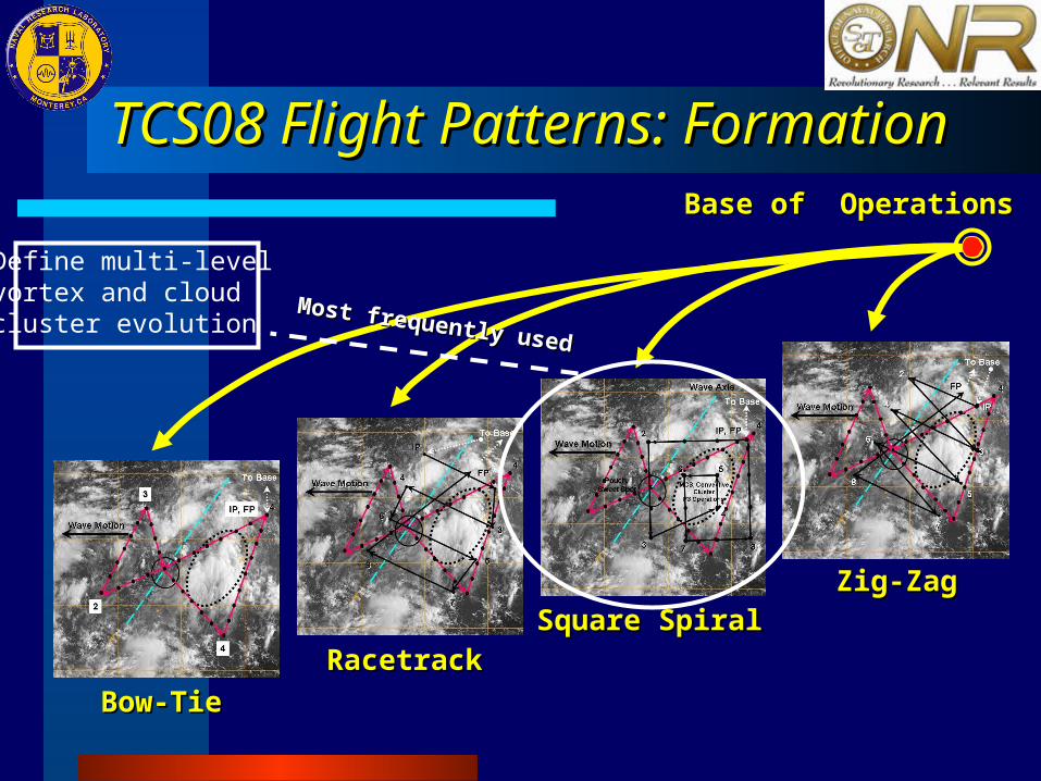
TCS08 Flight Patterns: FormationTCS08 Flight Patterns: FormationBase of OperationsBase of Operations
Bow-TieBow-Tie
RacetrackRacetrackSquare SpiralSquare Spiral
Zig-ZagZig-Zag
Define multi-levelvortex and cloud cluster evolution
Most frequently used
Most frequently used

TCS08 Flight Patterns: TC StructureTCS08 Flight Patterns: TC StructureBase of OperationsBase of Operations
Bow-TieBow-TieFigure 4Figure 4
ButterflyButterflyRotated Fig 4Rotated Fig 4
Define mean vortexObserve Pmin, Vmax
Define structure, TC asymmetries