Embed Size (px)
Citation preview

194 ®
0,5 ..........................3 ..................... 1990,7 ..........................6 ..................... 2001,0 ..........................9 ..................... 2011,25 ...................... 10 ..................... 2021,5 ........................ 12 ..................... 2032,0/3,0 ................15/19 ................... 204
0,5 ..........................4 ..................... 2050,7 ..........................5 ..................... 2061,0 ........................ 10 ..................... 2071,25/1,5 .............10/15 ................... 2082,0/2,5/3,0 ......16/20/25 ................ 209
1,5/2,0 ...............17/20 ................... 213
2,5/3,0/4,0 ......25/30/40 ................ 214
0,3 ..........................2 ..................... 2150,5 ..........................2 ..................... 2160,7 ..........................4 ..................... 2171,0 ..........................6,5 ................... 218
0,5* ........................4 ..................... 2190,7* ........................5 ..................... 2201,0* ........................6,5 ................... 2211,0...................... 10 / 15 ................. 2221,25 ...................... 10 ..................... 2241,5* ...................... 10 ..................... 2251,5..................... 15 / 17 .................. 2261,59 .... 12 ..................... 2482,0..................... 16 / 20 .................. 2282,5..................... 20 / 25 .................. 2303,0..................... 25 / 30 .................. 2323,18 ... 25 ..................... 2484,0..................... 30 / 40 .................. 2345,0... ..................40 / 50 .................. 2366,0..................... 50 / 60 .................. 2388,0*.......................65........ ............. 239
1,0/1,5 ................ 10/15 .................. 2422,0/3,0 ................ 20/25 .................. 243
1,0/1,5................10/15 ................... 2442,0/2,5................16/20 ................... 2453,0/4,0................25/30 ................... 2461,59 12 ...................... 2483,18 25...................... 248
1,0/1,5/2,0........ 15/15/20 .............. 2402,5/3,0.............. 25/30 ....................2414,0/5,0.............. 40/50....................241
1,0 ........................ 15 ..................... 2111,5 ........................ 17 ..................... 2112 ........................... 20 ..................... 2122,5 .......... .............25 ..................... 2123,0 ................. ......30 ..................... 212
Overview Spur Gears with Straight Tooth System
Spur gears: Acetal resin, die cast straight tooth system with hub
Spur gears: Plastic with core made from steel and stainless steel, with hub
Spur gears: Brass, straight tooth system with hub
Spur gears: Steel, straight tooth system with and without hub (* only with hub)
Precision Spur Gears: straight tooth system, hardened and ground
Spur gears: Stainless steel, straight tooth system with hub
Module Tooth width in mm Page
Spur gears: POM white, milled straight tooth system with hub
(pitch 5 mm)*
(pitch 10 mm)*
(pitch 5 mm)......(pitch 10 m).......
STAINLESS
STAINLESS
Spur Gears: straight tooth system, teeth hardened
Spur gears: POM black, milled straight tooth system with hub

195®
1,0/1,5,/2,0 ..... 200-250 ................. 247
0,5/0,7,/1,0 ......... 4/6/8 ................ 249
1,0/1,5/2,0 ........ 10/15/16............. 249
3,14 ......................4/9 ................... 2504,71 ......................6/9 ................... 250
0,3/0,5 ................. 5/10 .................. 251
1,0 .........................10 .................... 251
2,0/3,0 ...................28 .................... 252
4,0/5,0 ................ 40/50 ................. 253
255
Overview Spur Gear Elements with straight tooth system
Spur gear shafts: Steel, straight tooth system
Internal gears: Brass, straight tooth system
Internal gears: Steel, straight tooth system
Ratchet wheels and braces: Steel, straight tooth system
Overview Spur Gears with Helical Teeth
Spur gears: Brass, helical teeth, right hand
Spur gears: Steel, helical teeth, right hand and left hand
Spur gears: Steel, helical teeth, left hand, hardened and ground
Module Length in mm Page
Module Length in mm Page
Module Length in mm Page
Module Length in mm Page
Module Length in mm Page
Module Length in mm Page
Gear racksPage
Reworking within24h-service possible. Custom made parts
on request.

196 ®
d mda - 2m m to π
z . m
ts π
d +
da z + 2 d z
z . da z + 2
da -2m
(z + 2) . m
d +2 d z
d + 2 m
z1 + z2
2. m( (
d1 + d2
2 z2
z1
n1
n2
P n
9550 .
π . d . n
60.000
tn0 π
d + 2mn
da - 2 mn
z1 + z2
2
d1 + d2
2
mn
ms
+ 2
da
zcos ß
mn cos ß
d z
z . mn cos ß
z . da z + 2 . cos ß
( (+ 2 mn zcos ß
2 d . cos ß
z
( ( mn
cos ß
= cos ß
z . mn
d= cos ß
d . cos ß
mn
(da - 2 mn) . cos ß
mn
d . cos ß
z
General Basics for Spur Gears
Spur gears enable a non-slip power transmission between two parallel-mounted shafts. The spur gears listed in the catalogue are involute gears with a pressure angle of 20º.
Please note that gears with a number of teeth < 17 are undercut for manufacturing reasons (one reason for this is the simple cal-culation of the centre distance). The centre distance tolerances depend on the tooth quality in line with DIN 3964. The modules for spur gears used in the catalogue were derived from DIN 780 Series 1.
The formulas below apply to straight and helical spur gears for the usual gear-cutting tools (see table) and for the addendum modification 0 for sprocket and wheel (the so-called reference centre distance tooth system).
Module-Series 1
Module 0.3 Module 0.5 Module 0.7 Module 1.0 Module 1.25 Module 1.5 Module 2.0 Module 2.5 Module 3.0 Module 4.0 Module 5.0 Module 6.0 Module 8.0Module-Series 2
Module 0.75 Module 3.5 Module 7.0
Rotational direction changes with every gear
to be calculated given unit formula
No. of Teeth = z
Module = m in mm
Pitch Ø = d in mm
Tip Ø = da in mm
Centre distance = a in mm
Reduction Ratio = i
Torque = Md in Nm
Peripheral Speed = V in m/sec.
Material quality: Information about the material quality can be found at each individual group of gears.
d mda - 2m m
Teeth straight
Pitch Ø and Module Addendum-Circle Ø
Pitch
Tip Ø and No. of Teeth
Pitch Ø and No. of Teeth
No. of Teeth and Module
No. of Teeth and Tip Ø Tip Ø and Module
No. of Teeth and Module No. of Teeth and Pitch Ø Pitch Ø and Module
Teeth helicalto be calculated given unit formula
No. of Teeth = z
Module = m in mm
Pitch Ø = d in mm
Tip Ø = da in mm
Centre distance = a in mm
Reduction Ratio = i
Torque = Md in Nm
Peripheral Speed = V in m/sec.
Material quality: Information about the material quality can be found at each individual group of gears.
Pitch Ø and Speed [mm] [min-1]
No. of Teeth and Module Pitch Ø and Pitch Ø
No. of Teeth and No. of Teeth
Speed and Speed
Power and Speed [kW] [min-1]
to be calculated given unit formula
No. of Teeth
Normal Module
Real module
Pitch Ø
Tip Ø
Centre distance
Spiral Angle
Pitch Ø, Standard Module and Spiral AngleTip Ø, Standard Module and Spiral Angle
Standard Pitch Pitch Ø, No. of Teeth and Spiral Angle Tip Ø, No. of Teeth and Spiral Angle
Reference Circle Pitch
Standard Module and Spiral Angle
Pitch Ø and No. of Teeth
No. of Teeth, Standard Module and Spiral Angle Pitch Ø and Standard Module Pitch Ø, No. of Teeth and Spiral Angle
No. of Teeth, Standard Module and Spiral Angle No. of Teeth, Tip Ø and Spiral Angle Tip Ø and Standard Module
No. of Teeth, Standard Module and Spiral Angle Pitch Ø and Pitch Ø
Standard Module u. Real Module Standard Module, No. of Teeth and Pitch Ø
Recommendations for the Lubrication of Spur Gear Units
Peripheral Speed Lubrication Lubricant up to 1 m/s Application of Lubricant Adhesive Lubricant up to 4 m/s Splash Lubrication/Spray Lubrication Grease or Adh. Lubricant up to 15 m/s Splash Lubrication Oil over 15 m/s Pressure-Circulation or Spray Lubrication Oil

197®
Note Regarding the Torque-Values Stated in the Catalogue
The torque values given for gears in the dimension tables (the value “perm. MT” stated in Nm or Ncm) only relate to the teeth, without considering the shaft diameter or key size.
The load bearing capacity calculations are based on the basic prin-ciples regarding the pitting resistance of the tooth flanks and the occurring tooth root stress. The calculations are based on the DIN 3990 (Method B). For the calculation, the following assumptions were made:
Calcul. Factor/Determining Factor Abbreviation Value Note
Calculation Method - - DIN 3990, method B
DIN Quality - 8 -
Tooth-Number Ratio U 1 If U > 1, the flank safety for long and short addendum teeth increases while the tooth-root safety decreases For other tooth-number ratios please check both pinion and gear!
Manufacturing Tool: haP0/hfP0/rhoaPo 1.25/1/0.25 Hob Addendum/Dedendum/ Tip Rounding
Flank Safety SH 1.0 Endurance strength 10.000 h (for steel)
Tooth-Root Safety SF 1.5 Endurance strength 10.000 h (for steel)
Application Factor KA 1.25 Industrial gear mechanisms, uniform, light shocks.
Dynamics Factor KV 1.0 Usually without great influence
Load Distribution over Width KHbeta 1 Idealised; requires precise, rigid and symmetric mounting
Lubricant/Surface Roughness ZL *ZV *ZR 1 • sufficient oil-lubrication Speed Factor • relative surface roughness RZ100 = 10 • peripheral speed 10 m/s
Lifetime Factor ZN 1 Endurance strength 10.000 h (for steel)
Operating temperature for TBetr up to 60ºC The material parametres of plastic gears largely depend on the temperature plastic gears
Please make sure you always check the permissible torque sepa-rately for the pinion and the gear side! Due to their higher elasticity plastic gears are calculated with a
KHbeta of 1. Gears made from brass and zinc-die-cast are also cal-culated with a KHbeta of 1, as a good running-in characteristic is assumed for these materials.
The load bearing capacity of a gear depends on various different factors. The stated torques are only reference values, serving to facilitate the selection process. If necessary, a specific calculation of strength and load bearing capacity must be carried out for each application.
Depending on the operating conditions the wear lifespan may be influenced by adequate grease/oil lubrication. Please also note that insufficient lubrication may lead to scuffing of the gear flanks.
IMPORTANT
For the materials used, the following characteristic values were taken as basis:
s bw in N/mm2 s Hlim in N/mm2
28 (VDI-2545) 40 (VDI-2545) 28 (VDI-2545) 40 (VDI-2545) 40 48 60 150 100 250 150 350 200 590 350 1360 400 1630 200 400
Material Perm. Pulsating Fatigue Strength under Bending Stress Perm. Flank Pressure
POMAcetal ResinPA12GZnAl4Cu1Ms58 (2.0401)11SMnPb30 (alt: 9SMn28K)C45 heat treated42CrMo4 hardened16MnCr5 case hardenedX10CrNiS18 9 (1.4305, stainless, austenitic)
198 ®
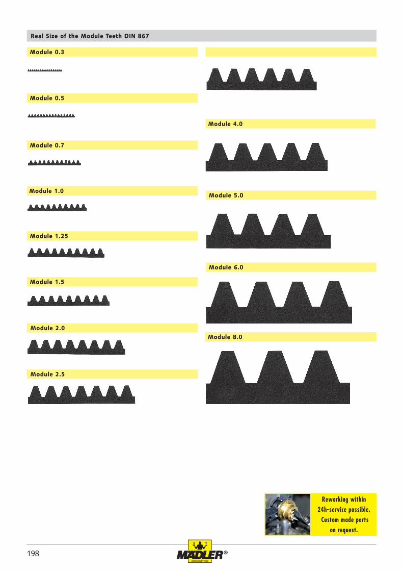
Module 0.3
Module 0.5
Module 0.7
Module 1.0
Module 1.25
Module 1.5
Module 2.0
Module 2.5
Module 4.0
Module 5.0
Module 6.0
Module 8.0
Real Size of the Module Teeth DIN 867
Reworking within
24h-service possible. Custom made parts
on request.