Embed Size (px)
Citation preview
Catalyst 2950 Deskto78-14982-02
C H A P T E R 1
OverviewThis chapter provides these topics about the Catalyst 2950 switch software:
• Features, page 1-1
• Management Options, page 1-7
• Network Configuration Examples, page 1-9
• Where to Go Next, page 1-23
FeaturesThe Catalyst 2950 software supports the switches listed in Table 1-1 and in the release notes.
Table 1-1 Switches Supported
SwitchSoftware Image
Catalyst 2950-12 SI1
1. SI = standard software image
Catalyst 2950-24 SI
Catalyst 2950C-24 EI2
2. EI = enhanced software image
Catalyst 2950G-12-EI EI
Catalyst 2950G-24-EI EI
Catalyst 2950G-24-EI-DC EI
Catalyst 2950G-48-EI EI
Catalyst 2950SX-24 SI
Catalyst 2950T-24 EI
Catalyst 2950ST-24 LRE EI
Catalyst 2950ST-8 LRE EI
Catalyst 2950ST-24 LRE 997 EI
1-1p Switch Software Configuration Guide
Chapter 1 OverviewFeatures
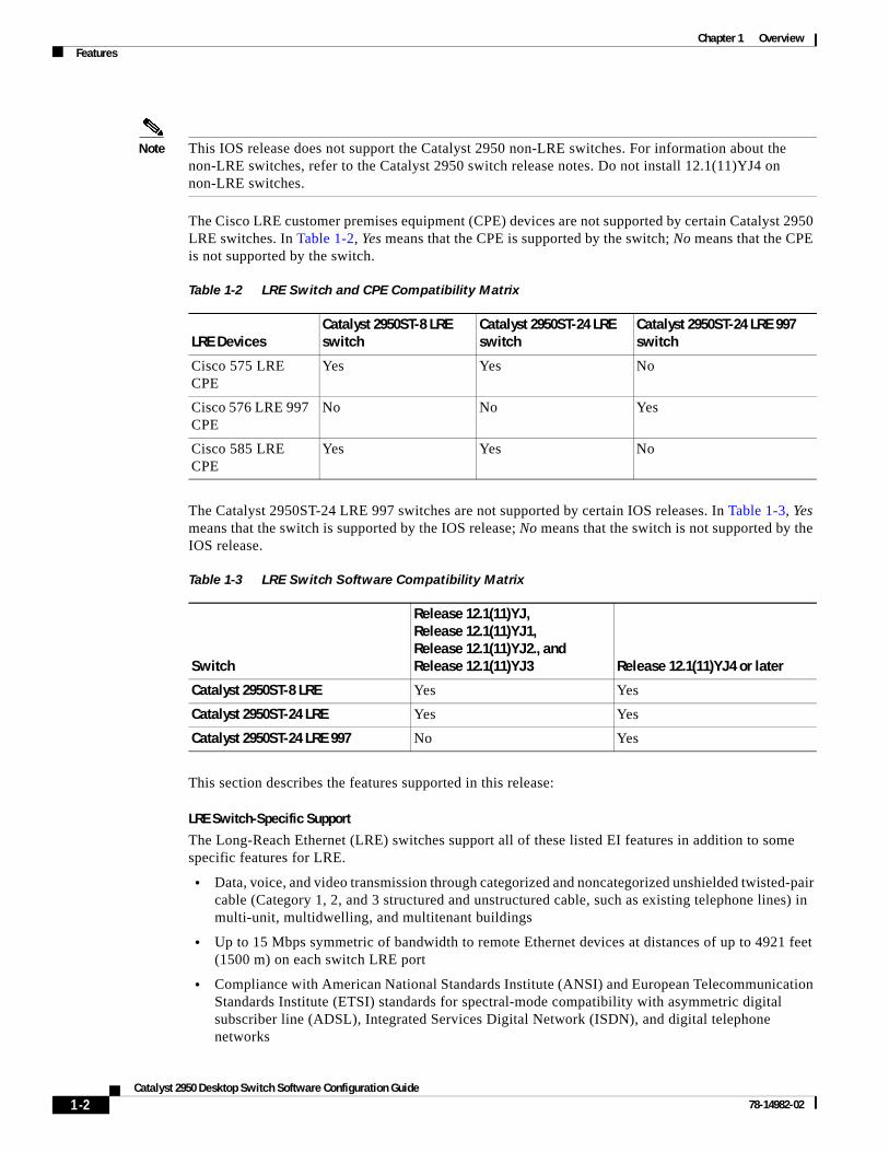
Note This IOS release does not support the Catalyst 2950 non-LRE switches. For information about the non-LRE switches, refer to the Catalyst 2950 switch release notes. Do not install 12.1(11)YJ4 on non-LRE switches.
The Cisco LRE customer premises equipment (CPE) devices are not supported by certain Catalyst 2950 LRE switches. In Table 1-2, Yes means that the CPE is supported by the switch; No means that the CPE is not supported by the switch.
The Catalyst 2950ST-24 LRE 997 switches are not supported by certain IOS releases. In Table 1-3, Yes means that the switch is supported by the IOS release; No means that the switch is not supported by the IOS release.
This section describes the features supported in this release:
LRE Switch-Specific Support
The Long-Reach Ethernet (LRE) switches support all of these listed EI features in addition to some specific features for LRE.
• Data, voice, and video transmission through categorized and noncategorized unshielded twisted-pair cable (Category 1, 2, and 3 structured and unstructured cable, such as existing telephone lines) in multi-unit, multidwelling, and multitenant buildings
• Up to 15 Mbps symmetric of bandwidth to remote Ethernet devices at distances of up to 4921 feet (1500 m) on each switch LRE port
• Compliance with American National Standards Institute (ANSI) and European Telecommunication Standards Institute (ETSI) standards for spectral-mode compatibility with asymmetric digital subscriber line (ADSL), Integrated Services Digital Network (ISDN), and digital telephone networks
Table 1-2 LRE Switch and CPE Compatibility Matrix
LRE DevicesCatalyst 2950ST-8 LRE switch
Catalyst 2950ST-24 LRE switch
Catalyst 2950ST-24 LRE 997 switch
Cisco 575 LRE CPE
Yes Yes No
Cisco 576 LRE 997 CPE
No No Yes
Cisco 585 LRE CPE
Yes Yes No
Table 1-3 LRE Switch Software Compatibility Matrix
Switch
Release 12.1(11)YJ, Release 12.1(11)YJ1, Release 12.1(11)YJ2., and Release 12.1(11)YJ3 Release 12.1(11)YJ4 or later
Catalyst 2950ST-8 LRE Yes Yes
Catalyst 2950ST-24 LRE Yes Yes
Catalyst 2950ST-24 LRE 997 No Yes
1-2Catalyst 2950 Desktop Switch Software Configuration Guide
78-14982-02
Chapter 1 OverviewFeatures
• Configuration and monitoring of connections between:
– Switch LRE ports and the Ethernet ports on remote LRE customer premises equipment (CPE) devices, such as the Cisco 575 LRE CPE, Cisco 576 LRE 997 CPE, and Cisco 585 LRE CPE
– CPE Ethernet ports and remote Ethernet devices, such as a PC
• Support for connecting to the public switched telephone network (PSTN) through plain old telephone service (POTS) splitters such as the Cisco LRE 48 POTS Splitter
• Support for the rate selection, a utility that allows for automatic selection of transmission rates through profiles and profile sequences
• A set of additional rate profiles
• Support for Reed-Solomon error correction
• Additional MIB support
• Support for the secure shell (SSH) and SNMPv3 crypto, with a protected port on 585 CPE devices
• Support for small form-factor pluggable (SFP) devices instead of gigabit interface converters (GBIC); GigaStack is not supported on the 2950 LRE
• Interleave delay for providing maximum protection against small interruptions on the LRE link
• Upstream power back-off mechanism for normalization of the upstream receive power levels by requiring the CPE devices on shorter lines to transmit at a lower power level than the CPEs on longer lines
• The Catalyst 2950ST-24 LRE 997 switches provide DC-input power and are compliant with the VDSL 997 band plan
Note Most Catalyst 2950 features also work on the Catalyst 2950 LRE switch, with the difference that LRE switches use Long-Reach Ethernet rather than Fast Ethernet and Gigabit for the Gigabit ports.
For information about the Cisco LRE CPE devices, refer to the Cisco LRE CPE Hardware Installation Guide. For information about the nonhomologated Cisco LRE POTS splitter, refer to the Installation Notes for the Cisco LRE 48 POTS Splitter.
Ease of Use and Ease of Deployment
• Cluster Management Suite (CMS) software for simplifying switch and switch cluster management through a web browser, such as Netscape Communicator or Microsoft Internet Explorer, from anywhere in your intranet
• Switch clustering technology used with CMS for
– Unified configuration, monitoring, authentication, and software upgrade of multiple switches (refer to the release notes for a list of eligible cluster members).
– Automatic discovery of candidate switches and creation of clusters of up to 16 switches that can be managed through a single IP address.
– Extended discovery of cluster candidates that are not directly connected to the command switch.
• Hot Standby Router Protocol (HSRP) for command-switch redundancy. The redundant command switches used for HSRP must have compatible software releases.
Note See the “Advantages of Using CMS and Clustering Switches” section on page 1-8. Refer to the switch hardware guide for the CMS, cluster hardware, software, and browser requirements. Refer to the release notes for the cluster hardware and software requirements.
1-3Catalyst 2950 Desktop Switch Software Configuration Guide
78-14982-02
Chapter 1 OverviewFeatures
Performance
• Autosensing of speed on the 10/100 and 10/100/1000 ports and autonegotiation of duplex mode on the 10/100 ports for optimizing bandwidth
• IEEE 802.3X flow control on Gigabit Ethernet ports operating in full-duplex mode
• Fast EtherChannel and Gigabit EtherChannel for enhanced fault tolerance and for providing up to 2 Gbps of bandwidth between switches, routers, and servers
• Support for frames larger than 1500 bytes. The Catalyst 2950G-12-EI, 2950G-24-EI, 2950G-24-EI-DC, and 2950G-48-EI switches running Cisco IOS Release 12.1(6)EA2 or later support frame sizes from 1500 to 1530 bytes
• Per-port broadcast storm control for preventing faulty end stations from degrading overall system performance with broadcast storms
• Port Aggregation Protocol (PAgP) for automatic creation of EtherChannel links
• Internet Group Management Protocol (IGMP) snooping support to limit flooding of IP multicast traffic
• Multicast VLAN registration (MVR) to continuously send multicast streams in a multicast VLAN while isolating the streams from subscriber VLANs for bandwidth and security reasons
• IGMP filtering for controlling the set of multicast groups to which hosts on a switch port can belong
• Protected port (private VLAN edge port) option for restricting the forwarding of traffic to designated ports on the same switch
• Dynamic address learning for enhanced security
Manageability
• Cisco Intelligence Engine 2100 (IE2100) Series Cisco Networking Services (CNS) embedded agents for automating switch management, configuration storage and delivery (available only with the EI)
• Dynamic Host Configuration Protocol (DHCP)-based autoconfiguration for automatically configuring the switch during startup with IP address information and a configuration file that it receives during DHCP-based autoconfiguration
Note DHCP replaces the Bootstrap Protocol (BOOTP) feature autoconfiguration to ensure retrieval of configuration files by unicast TFTP messages. BOOTP is available in earlier software releases for this switch.
• Address Resolution Protocol (ARP) for identifying a switch through its IP address and its corresponding MAC address
• Cisco Discovery Protocol (CDP) versions 1 and 2 for network topology discovery and mapping between the switch and other Cisco devices on the network
• Network Time Protocol (NTP) for providing a consistent timestamp to all switches from an external source
• Directed unicast requests to a Trivial File Transfer Protocol (TFTP) server for obtaining software upgrades from a TFTP server
• Default configuration storage in Flash memory to ensure that the switch can be connected to a network and can forward traffic with minimal user intervention
• In-band management access through a CMS web-based session
1-4Catalyst 2950 Desktop Switch Software Configuration Guide
78-14982-02
Chapter 1 OverviewFeatures
• In-band management access through up to 16 simultaneous Telnet connections for multiple command-line interface (CLI)-based sessions over the network
• In-band management access through Simple Network Management Protocol (SNMP) versions 1, 2c, and 3 get and set requests
• Out-of-band management access through the switch console port to a directly-attached terminal or to a remote terminal through a serial connection and a modem
Note For additional descriptions of the management interfaces, see the “Management Options” section on page 1-7.
Redundancy
• HSRP for command-switch redundancy
• UniDirectional link detection (UDLD) on all Ethernet ports for detecting and disabling unidirectional links on fiber-optic interfaces caused by incorrect fiber-optic wiring or port faults
• IEEE 802.1D Spanning Tree Protocol (STP) for redundant backbone connections and loop-free networks. STP has these features:
– Per-VLAN Spanning Tree (PVST) for balancing load across VLANs
– UplinkFast, cross-stack UplinkFast, and BackboneFast for fast convergence after a spanning-tree topology change and for achieving load balancing between redundant uplinks, including Gigabit uplinks and cross-stack Gigabit uplinks
• IEEE 802.1S Multiple STP (MSTP) for grouping VLANs into a spanning-tree instance, and providing for multiple forwarding paths for data traffic and load balancing (available only with the EI)
• IEEE 802.1W Rapid STP (RSTP) for rapid convergence of the spanning tree by immediately transitioning root and designated ports to the forwarding state (available only with the EI)
• Optional spanning-tree features available:
– Port Fast for eliminating the forwarding delay by enabling a port to immediately transition from the blocking state to the forwarding state
– BPDU guard for shutting down Port Fast-enabled ports that receive BPDUs
– BPDU filtering for preventing a Port Fast-enabled port from sending or receiving BPDUs
– Root guard for preventing switches outside the network core from becoming the spanning-tree root
– Loop guard for preventing alternate or root ports from becoming designated ports because of a failure that leads to a unidirectional link
Note The switch supports up to 64 spanning-tree instances.
VLAN Support
• The switches support 250 port-based VLANs for assigning users to VLANs associated with appropriate network resources, traffic patterns, and bandwidth
Note The Catalyst 2950-12, Catalyst 2950-24, and Catalyst 2950SX-24 switches support only 64 port-based VLANs.
1-5Catalyst 2950 Desktop Switch Software Configuration Guide
78-14982-02
Chapter 1 OverviewFeatures
• The switch supports up to 4094 VLAN IDs to allow service provider networks to support the number of VLANs allowed by the IEEE 802.1Q standard (available only with the EI)
• IEEE 802.1Q trunking protocol on all ports for network moves, adds, and changes; management and control of broadcast and multicast traffic; and network security by establishing VLAN groups for high-security users and network resources
• VLAN Membership Policy Server (VMPS) for dynamic VLAN membership
• VLAN Trunking Protocol (VTP) pruning for reducing network traffic by restricting flooded traffic to links destined for stations receiving the traffic
• Dynamic Trunking Protocol (DTP) for negotiating trunking on a link between two devices and for negotiating the type of trunking encapsulation (802.1Q) to be used
• Voice VLAN for creating subnets for voice traffic from Cisco IP Phones
Security
• Bridge protocol data unit (BPDU) guard for shutting down a Port Fast-configured port when an invalid configuration occurs
• Protected port option for restricting the forwarding of traffic to designated ports on the same switch
• Password-protected access (read-only and read-write access) to management interfaces (CMS and CLI) for protection against unauthorized configuration changes
• Port security option for limiting and identifying MAC addresses of the stations allowed to access the port
• Port security aging to set the aging time for secure addresses on a port
• Multilevel security for a choice of security level, notification, and resulting actions
• MAC-based port-level security for restricting the use of a switch port to a specific group of source addresses and preventing switch access from unauthorized stations (available only with the EI)
• Terminal Access Controller Access Control System Plus (TACACS+), a proprietary feature for managing network security through a TACACS server
• IEEE 802.1X port-based authentication to prevent unauthorized devices from gaining access to the network
• Standard and extended IP access control lists (ACLs) for defining security policies (available only with the EI)
Quality of Service and Class of Service
• Classification
– IEEE 802.1P class of service (CoS) with four priority queues on the switch 10/100 and LRE ports and eight priority queues on the Gigabit ports for prioritizing mission-critical and time-sensitive traffic from data, voice, and telephony applications
– IP Differentiated Services Code Point (IP DSCP) and class of service (CoS) marking priorities on a per-port basis for protecting the performance of mission-critical applications (only available with the EI)
– Flow-based packet classification (classification based on information in the MAC, IP, and TCP/UDP headers) for high-performance quality of service at the network edge, allowing for differentiated service levels for different types of network traffic and for prioritizing mission-critical traffic in the network (only available in the EI)
– Support for IEEE 802.1P CoS scheduling for classification and preferential treatment of high-priority voice traffic
1-6Catalyst 2950 Desktop Switch Software Configuration Guide
78-14982-02
Chapter 1 OverviewManagement Options
– Trusted boundary (detect the presence of a Cisco IP phone, trust the CoS value received, and ensure port security. If the IP phone is not detected, disable the trusted setting on the port and prevent misuse of a high-priority queue.)
• Policing
– Traffic-policing policies on the switch port for allocating the amount of the port bandwidth to a specific traffic flow
– Policing traffic flows to restrict specific applications or traffic flows to metered, predefined rates
– Up to 60 policers on ingress Gigabit-capable Ethernet ports Up to six policers on ingress 10/100 ports Granularity of 1 Mbps on 10/100 ports and 8 Mbps on 10/100/1000 ports
– Out-of-profile markdown for packets that exceed bandwidth utilization limits
Note Policing is available only in the EI.
• Egress Policing and Scheduling of Egress Queues—Four egress queues on all switch ports. Support for strict priority and weighted round-robin (WRR) CoS policies
Monitoring
• Switch LEDs that provide visual port and switch status
• Switched Port Analyzer (SPAN) and Remote SPAN (RSPAN) for traffic monitoring on any port or VLAN
Note RSPAN is available only in the EI.
• Four groups (history, statistics, alarms, and events) of embedded remote monitoring (RMON) agents for network monitoring and traffic analysis
• MAC address notification for tracking the MAC addresses that the switch has learned or removed
• Syslog facility for logging system messages about authentication or authorization errors, resource issues, and time-out events
Management OptionsThe switches are designed for plug-and-play operation: you only need to assign basic IP information to the switch and connect it to the other devices in your network. If you have specific network needs, you can configure and monitor the switch—on an individual basis or as part of a switch cluster—through its various management interfaces.
This section discusses these topics:
• Management Interface Options, page 1-8
• Advantages of Using CMS and Clustering Switches, page 1-8
1-7Catalyst 2950 Desktop Switch Software Configuration Guide
78-14982-02
Chapter 1 OverviewManagement Options
Management Interface OptionsYou can configure and monitor individual switches and switch clusters by using these interfaces:
• CMS—CMS is a graphical user interface that can be launched from anywhere in your network through a web browser such as Netscape Communicator or Microsoft Internet Explorer. CMS is already installed on the switch. Using CMS, you can configure and monitor a standalone switch, a specific cluster member, or an entire switch cluster. You can also display network topologies to gather link information and display switch images to modify switch and port level settings.
For more information about CMS, see Chapter 3, “Getting Started with CMS.”
• CLI—The switch IOS CLI software is enhanced to support desktop-switching features. You can configure and monitor the switch and switch cluster members from the CLI. You can access the CLI either by connecting your management station directly to the switch console port or by using Telnet from a remote management station.
For more information about the CLI, see Chapter 2, “Using the Command-Line Interface.”
• IE2100—Cisco Intelligence Engine 2100 Series Configuration Registrar is a network management device that works with embedded CNS Agents in the switch software. You can automate initial configurations and configuration updates by generating switch-specific configuration changes, sending them to the switch, executing the configuration change, and logging the results.
For more information about IE2100, see Chapter 5, “Configuring IE2100 CNS Agents.”
• SNMP—SNMP provides a means to monitor and control the switch and switch cluster members. You can manage switch configuration settings, performance, and security and collect statistics by using SNMP management applications such as CiscoWorks2000 LAN Management Suite (LMS) and HP OpenView.
You can manage the switch from an SNMP-compatible management station that is running platforms such as HP OpenView or SunNet Manager. The switch supports a comprehensive set of MIB extensions and four RMON groups.
For more information about using SNMP, see the Chapter 24, “Configuring SNMP.”
Advantages of Using CMS and Clustering SwitchesUsing CMS and switch clusters can simplify and minimize your configuration and monitoring tasks. You can use Cisco switch clustering technology to manage up to 16 interconnected and supported Catalyst switches through one IP address as if they were a single entity. This can conserve IP addresses if you have a limited number of them. CMS is the easiest interface to use and makes switch and switch cluster management accessible to authorized users from any PC on your network.
By using switch clusters and CMS, you can:
• Manage and monitor interconnected Catalyst switches (refer to the release notes for a list of supported switches), regardless of their geographic proximity and interconnection media, including Ethernet, Fast Ethernet, Fast EtherChannel, Cisco GigaStack Gigabit Interface Converter (GBIC), Gigabit Ethernet, and Gigabit EtherChannel connections.
• Accomplish multiple configuration tasks from a single CMS window without needing to remember CLI commands to accomplish specific tasks.
1-8Catalyst 2950 Desktop Switch Software Configuration Guide
78-14982-02
Chapter 1 OverviewNetwork Configuration Examples
• Apply actions from CMS to multiple ports and multiple switches at the same time to avoid re-entering the same commands for each individual port or switch. Here are some examples of globally setting and managing multiple ports and switches:
– Port configuration such as speed and duplex settings
– Port and console port security settings
– NTP, STP, VLAN, and quality of service (QoS) configurations
– Inventory and statistic reporting and link and switch-level monitoring and troubleshooting
– Group software upgrades
• View a topology of interconnected devices to identify existing switch clusters and eligible switches that can join a cluster. You can also use the topology to quickly identify link information between switches.
• Monitor real-time status of a switch or multiple switches from the LEDs on the front-panel images. The system, redundant power system (RPS), and port LED colors on the images are similar to those on the physical LEDs.
• Use an interactive mode that takes you step-by-step through configuring complex features such as VLANs, ACLs, and QoS.
• Use a wizard that prompts you to provide the minimum required information to configure complex features such as QoS priorities for video traffic, priority levels for data applications, and security.
For more information about CMS, see Chapter 3, “Getting Started with CMS.” For more information about switch clusters, see Chapter 6, “Clustering Switches.”
Network Configuration ExamplesThis section provides network configuration concepts and includes examples of using the switch to create dedicated network segments and interconnecting the segments through Fast Ethernet and Gigabit Ethernet connections.
Design Concepts for Using the SwitchAs your network users compete for network bandwidth, it takes longer to send and receive data. When you configure your network, consider the bandwidth required by your network users and the relative priority of the network applications they use.
Table 1-4 describes what can cause network performance to degrade and how you can configure your network to increase the bandwidth available to your network users.
1-9Catalyst 2950 Desktop Switch Software Configuration Guide
78-14982-02
Chapter 1 OverviewNetwork Configuration Examples
Bandwidth alone is not the only consideration when designing your network. As your network traffic profiles evolve, consider providing network services that can support applications such as voice and data integration and security.
Table 1-5 describes some network demands and how you can meet those demands.
Figure 1-1 shows configuration examples of using the Catalyst switches to create these networks:
• Cost-effective wiring closet—A cost-effective way to connect many users to the wiring closet is to connect up to nine Catalyst 2900 XL, Catalyst 2950, Catalyst 3500 XL, and Catalyst 3550 switches through GigaStack GBIC connections. When you use a stack of Catalyst 2950G-48 switches, you can connect up to 432 users. To preserve switch connectivity if one switch in the stack fails, connect the bottom switch to the top switch to create a GigaStack loopback, and enable cross-stack UplinkFast on the cross-stack Gigabit uplinks.
Table 1-4 Increasing Network Performance
Network Demands Suggested Design Methods
Too many users on a single network segment and a growing number of users accessing the Internet
• Create smaller network segments so that fewer users share the bandwidth, and use VLANs and IP subnets to place the network resources in the same logical network as the users who access those resources most.
• Use full-duplex operation between the switch and its connected workstations.
• Increased power of new PCs, workstations, and servers
• High demand from networked applications (such as e-mail with large attached files) and from bandwidth-intensive applications (such as multimedia)
• Connect global resources—such as servers and routers to which network users require equal access—directly to the Fast Ethernet or Gigabit Ethernet switch ports so that they have their own Fast Ethernet or Gigabit Ethernet segment.
• Use the Fast EtherChannel or Gigabit EtherChannel feature between the switch and its connected servers and routers.
Table 1-5 Providing Network Services
Network Demands Suggested Design Methods
High demand for multimedia support • Use IGMP and MVR to efficiently forward multicast traffic.
High demand for protecting mission-critical applications
• Use VLANs and protected ports to provide security and port isolation.
• Use VLAN trunks, cross-stack UplinkFast, and BackboneFast for traffic-load balancing on the uplink ports so that the uplink port with a lower relative port cost is selected to carry the VLAN traffic.
An evolving demand for IP telephony • Use QoS to prioritize applications such as IP telephony during congestion and to help control both delay and jitter within the network.
• Use switches that support at least two queues per port to prioritize voice and data traffic as either high- or low-priority, based on 802.1P/Q.
A growing demand for using existing infrastructure to transport data and voice from a home or office to the Internet or an intranet at higher speeds
• Use the Catalyst 2950 LRE switches to provide up to 15 Mb of IP connectivity over existing infrastructure (existing telephone lines).
1-10Catalyst 2950 Desktop Switch Software Configuration Guide
78-14982-02
Chapter 1 OverviewNetwork Configuration Examples
You can create backup paths by using Fast Ethernet, Gigabit, Fast EtherChannel, or Gigabit EtherChannel links. Using Gigabit modules on two of the switches, you can have redundant uplink connections to a Gigabit backbone switch such as the Catalyst 3550-12G switch. If one of the redundant connections fails, the other can serve as a backup path. You can configure the stack members and the Catalyst 3550-12G switch as a switch cluster to manage them through a single IP address.
• High-performance workgroup—For users who require high-speed access to network resources, use Gigabit modules to connect the switches directly to a backbone switch in a star configuration. Each switch in this configuration provides users with a dedicated 1-Gbps connection to network resources in the backbone. Compare this with the switches in a GigaStack configuration, where the 1-Gbps connection is shared among the switches. With the high speed uplink to the distribution server, the user can efficiently obtain and store data from servers. Using these Gigabit modules also provides flexibility in media and distance options:
– 1000BASE-T GBIC: copper connections of up to 328 feet (100 meters)
– 1000BASE-SX GBIC: fiber-optic connections of up to 1804 feet (550 meters)
– 1000BASE-LX/LH GBIC: fiber-optic connections of up to 32,808 feet (10 kilometers)
– 1000BASE-ZX GBIC: fiber-optic connections of up to 328,084 feet (100 kilometers)
– GigaStack GBIC module for creating a 1-Gbps stack configuration of up to nine supported switches. The GigaStack GBIC supports one full-duplex link (in a point-to-point configuration) or up to nine half-duplex links (in a stack configuration) to other Gigabit Ethernet devices. Using the required Cisco proprietary signaling and cabling, the GigaStack GBIC-to-GigaStack GBIC connection cannot exceed 3 feet (1 meter).
– Catalyst 2950 LRE switches support SFP as well as 10/100/1000 copper connections
• Redundant Gigabit backbone—Using HSRP, you can create backup paths between Catalyst 3550-12T-L3 switches. To enhance network reliability and load balancing for different VLANs and subnets, you can connect the Catalyst 2950 switches, again in a star configuration, to two backbone switches. If one of the backbone switches fails, the second backbone switch preserves connectivity between the switches and network resources.
1-11Catalyst 2950 Desktop Switch Software Configuration Guide
78-14982-02
Chapter 1 OverviewNetwork Configuration Examples
Figure 1-1 Example Configurations
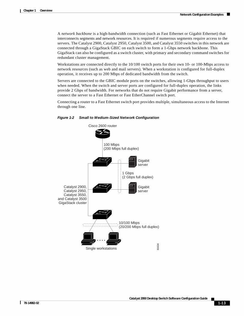
Small to Medium-Sized Network ConfigurationFigure 1-2 shows a configuration for a network that has up to 250 users. Users in this network require e-mail, file-sharing, database, and Internet access.
You optimize network performance by placing workstations on the same logical segment as the servers they access most often. This divides the network into smaller segments (or workgroups) and reduces the amount of traffic that travels over a network backbone, thereby increasing the bandwidth available to each user and improving server response time.
Si
Si
Si
Catalyst 2900, Catalyst 2950,Catalyst 3500,and Catalyst 3550GigaStack cluster
1-Gbps HSRP
8163
3
Catalyst 2950 switch
Cost-EffectiveWiring Closet
High-PerformanceWorkgroup
Redundant GigabitBackbone
Catalyst 3550-12T orCatalyst 3550-12G switch
Gigabitserver
Catalyst 2900, Catalyst 2950,Catalyst 3500, and Catalyst 3550 cluster
Catalyst 3550-12T orCatalyst 3550-12G switch
Catalyst 3550-12T orCatalyst 3550-12G switch
Catalyst 2900, Catalyst 2950, Catalyst 3500, and Catalyst 3550 cluster
1-12Catalyst 2950 Desktop Switch Software Configuration Guide
78-14982-02
Chapter 1 OverviewNetwork Configuration Examples
A network backbone is a high-bandwidth connection (such as Fast Ethernet or Gigabit Ethernet) that interconnects segments and network resources. It is required if numerous segments require access to the servers. The Catalyst 2900, Catalyst 2950, Catalyst 3500, and Catalyst 3550 switches in this network are connected through a GigaStack GBIC on each switch to form a 1-Gbps network backbone. This GigaStack can also be configured as a switch cluster, with primary and secondary command switches for redundant cluster management.
Workstations are connected directly to the 10/100 switch ports for their own 10- or 100-Mbps access to network resources (such as web and mail servers). When a workstation is configured for full-duplex operation, it receives up to 200 Mbps of dedicated bandwidth from the switch.
Servers are connected to the GBIC module ports on the switches, allowing 1-Gbps throughput to users when needed. When the switch and server ports are configured for full-duplex operation, the links provide 2 Gbps of bandwidth. For networks that do not require Gigabit performance from a server, connect the server to a Fast Ethernet or Fast EtherChannel switch port.
Connecting a router to a Fast Ethernet switch port provides multiple, simultaneous access to the Internet through one line.
Figure 1-2 Small to Medium-Sized Network Configuration
100 Mbps(200 Mbps full duplex)
Single workstations
Gigabitserver
8163
4
Cisco 2600 router
Gigabitserver
10/100 Mbps(20/200 Mbps full duplex)
1 Gbps(2 Gbps full duplex)
Catalyst 2900,Catalyst 2950,Catalyst 3550,
and Catalyst 3500GigaStack cluster
1-13Catalyst 2950 Desktop Switch Software Configuration Guide
78-14982-02
Chapter 1 OverviewNetwork Configuration Examples
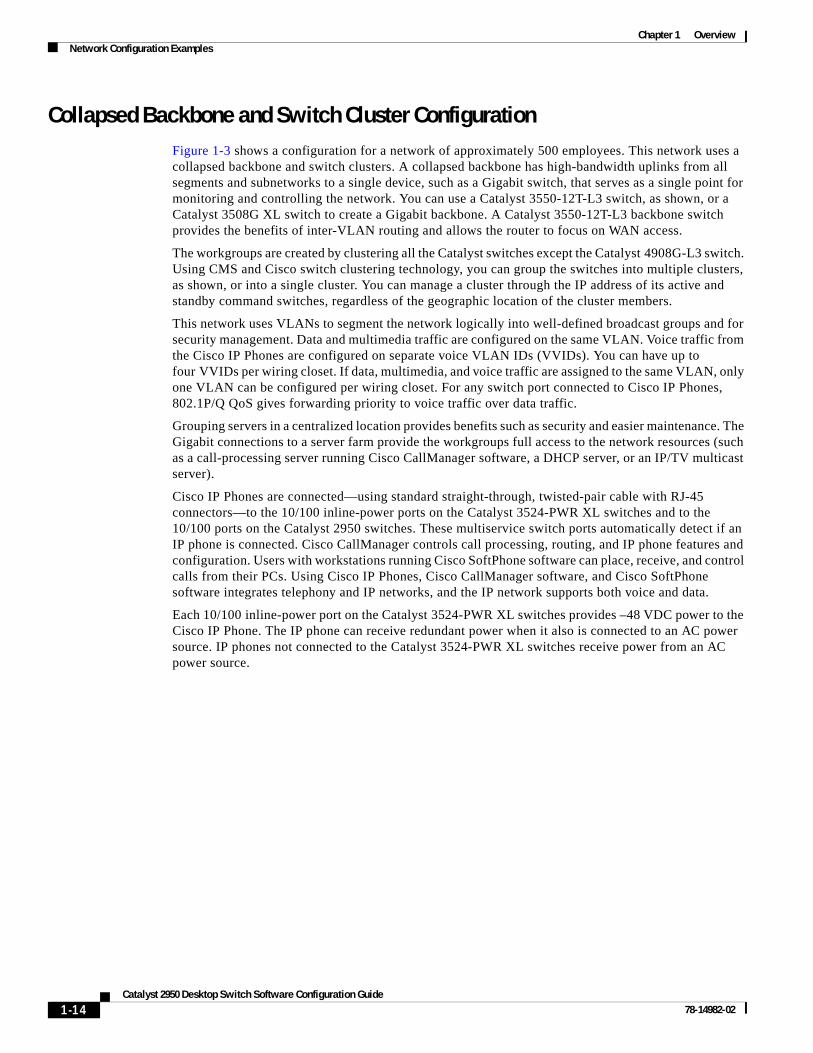
Collapsed Backbone and Switch Cluster ConfigurationFigure 1-3 shows a configuration for a network of approximately 500 employees. This network uses a collapsed backbone and switch clusters. A collapsed backbone has high-bandwidth uplinks from all segments and subnetworks to a single device, such as a Gigabit switch, that serves as a single point for monitoring and controlling the network. You can use a Catalyst 3550-12T-L3 switch, as shown, or a Catalyst 3508G XL switch to create a Gigabit backbone. A Catalyst 3550-12T-L3 backbone switch provides the benefits of inter-VLAN routing and allows the router to focus on WAN access.
The workgroups are created by clustering all the Catalyst switches except the Catalyst 4908G-L3 switch. Using CMS and Cisco switch clustering technology, you can group the switches into multiple clusters, as shown, or into a single cluster. You can manage a cluster through the IP address of its active and standby command switches, regardless of the geographic location of the cluster members.
This network uses VLANs to segment the network logically into well-defined broadcast groups and for security management. Data and multimedia traffic are configured on the same VLAN. Voice traffic from the Cisco IP Phones are configured on separate voice VLAN IDs (VVIDs). You can have up to four VVIDs per wiring closet. If data, multimedia, and voice traffic are assigned to the same VLAN, only one VLAN can be configured per wiring closet. For any switch port connected to Cisco IP Phones, 802.1P/Q QoS gives forwarding priority to voice traffic over data traffic.
Grouping servers in a centralized location provides benefits such as security and easier maintenance. The Gigabit connections to a server farm provide the workgroups full access to the network resources (such as a call-processing server running Cisco CallManager software, a DHCP server, or an IP/TV multicast server).
Cisco IP Phones are connected—using standard straight-through, twisted-pair cable with RJ-45 connectors—to the 10/100 inline-power ports on the Catalyst 3524-PWR XL switches and to the 10/100 ports on the Catalyst 2950 switches. These multiservice switch ports automatically detect if an IP phone is connected. Cisco CallManager controls call processing, routing, and IP phone features and configuration. Users with workstations running Cisco SoftPhone software can place, receive, and control calls from their PCs. Using Cisco IP Phones, Cisco CallManager software, and Cisco SoftPhone software integrates telephony and IP networks, and the IP network supports both voice and data.
Each 10/100 inline-power port on the Catalyst 3524-PWR XL switches provides –48 VDC power to the Cisco IP Phone. The IP phone can receive redundant power when it also is connected to an AC power source. IP phones not connected to the Catalyst 3524-PWR XL switches receive power from an AC power source.
1-14Catalyst 2950 Desktop Switch Software Configuration Guide
78-14982-02
Chapter 1 OverviewNetwork Configuration Examples
Figure 1-3 Collapsed Backbone and Switch Cluster Configuration
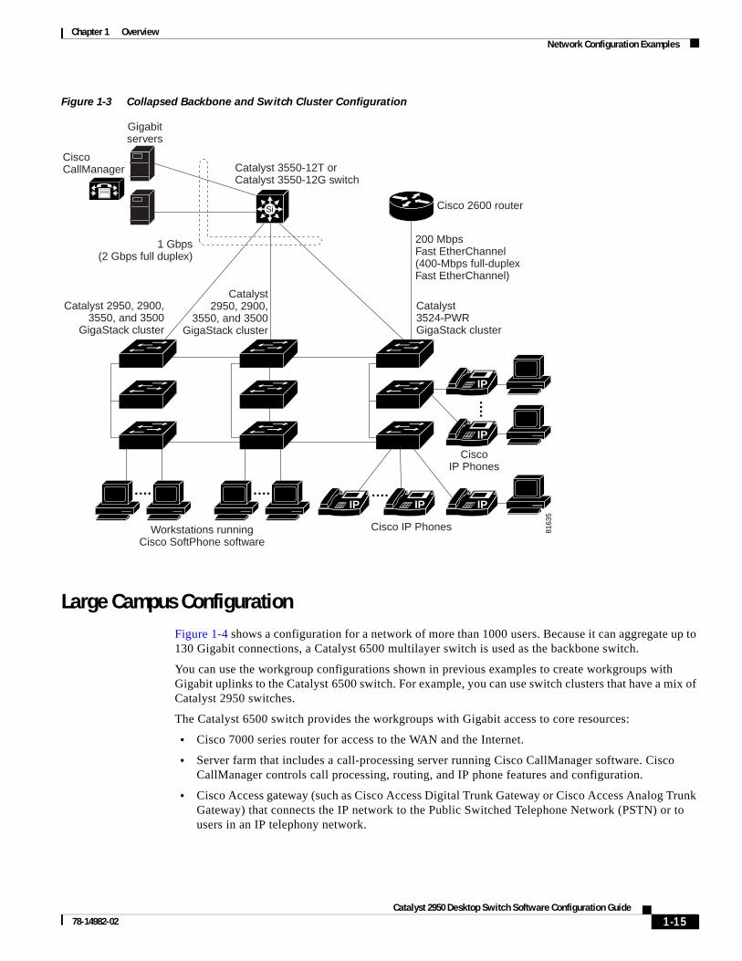
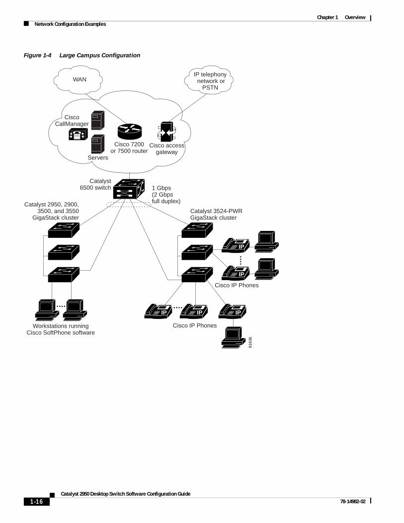
Large Campus ConfigurationFigure 1-4 shows a configuration for a network of more than 1000 users. Because it can aggregate up to 130 Gigabit connections, a Catalyst 6500 multilayer switch is used as the backbone switch.
You can use the workgroup configurations shown in previous examples to create workgroups with Gigabit uplinks to the Catalyst 6500 switch. For example, you can use switch clusters that have a mix of Catalyst 2950 switches.
The Catalyst 6500 switch provides the workgroups with Gigabit access to core resources:
• Cisco 7000 series router for access to the WAN and the Internet.
• Server farm that includes a call-processing server running Cisco CallManager software. Cisco CallManager controls call processing, routing, and IP phone features and configuration.
• Cisco Access gateway (such as Cisco Access Digital Trunk Gateway or Cisco Access Analog Trunk Gateway) that connects the IP network to the Public Switched Telephone Network (PSTN) or to users in an IP telephony network.
IP IP IP
IP
Catalyst 3550-12T orCatalyst 3550-12G switch
200 MbpsFast EtherChannel(400-Mbps full-duplexFast EtherChannel)
Gigabitservers
CiscoCallManager
8163
5
Cisco 2600 router
1 Gbps(2 Gbps full duplex)
CiscoIP Phones
Cisco IP PhonesWorkstations runningCisco SoftPhone software
Catalyst2950, 2900,
3550, and 3500GigaStack cluster
Catalyst3524-PWRGigaStack cluster
Catalyst 2950, 2900,3550, and 3500
GigaStack cluster
IP
Si
1-15Catalyst 2950 Desktop Switch Software Configuration Guide
78-14982-02
Chapter 1 OverviewNetwork Configuration Examples
Figure 1-4 Large Campus Configuration
Catalyst6500 switch
Cisco accessgateway
Servers
CiscoCallManager
Cisco 7200or 7500 router
WANIP telephony network or
PSTN
IP IP IP
IP
8163
6
Catalyst 3524-PWRGigaStack cluster
1 Gbps(2 Gbpsfull duplex)
IP
Cisco IP Phones
Cisco IP PhonesWorkstations runningCisco SoftPhone software
Catalyst 2950, 2900,3500, and 3550
GigaStack cluster
1-16Catalyst 2950 Desktop Switch Software Configuration Guide
78-14982-02
Chapter 1 OverviewNetwork Configuration Examples
Hotel Network ConfigurationFigure 1-5 shows the Catalyst 2950ST-8 LRE and 2950ST-24 LRE switches in a hotel network environment with approximately 200 rooms. This network includes a PBX switchboard, a router, and high-speed servers.
Connected to the telephone line in each hotel room is an LRE CPE device, such as a Cisco LRE CPE device. The LRE CPE device provides:
• Two RJ-11 ports, one for connecting to the telephone jack on the wall and one for connecting to a POTS telephone.
• One or more RJ-45 Ethernet ports for connecting to devices such as a customer’s laptop, the room’s IP phone, the television set-top box, or a room environmental control device. A Cisco 575 LRE CPE provides one Ethernet connection; a Cisco 585 LRE CPE provides four.
When connected to the CPE device, the Ethernet devices and room telephone share the same telephone line.
Note All telephones not directly connected to the hotel room CPE device require microfilters with a 300-ohm termination. Microfilters improve voice call quality when voice and data equipment are using the same telephone line. They also prevent nonfiltered telephone rings and nonfiltered telephone transitions (such as on-hook to off-hook) from interrupting the Ethernet connection.
Through a patch panel, the telephone line from each room connects to a nonhomologated POTS splitter, such as the Cisco LRE 48 POTS Splitter. The splitter routes data (high-frequency) and voice (low-frequency) traffic from the telephone line to a Catalyst 2950 LRE switch and digital private branch exchange (PBX). The PBX routes voice traffic to the PSTN.
If a PBX is not on-site, a homologated POTS splitter is required to connect directly to the PSTN.
Note Consult the regulations for connecting to the PSTN in your area.
If a connection to a phone network is not required at all, a splitter is not needed, and the switch can connect directly to the patch panel.
Note Cisco LRE products can share lines with analog telephones, Integrated Services Digital Network (ISDN) telephone network, and PBX switches that use the 0 to 700 kHz frequency range.
Data to and from the room devices (such as e-mail for the laptop and IP multicast traffic for the television) are transferred through the LRE link, which is established between the CPE RJ-11 wall port and the LRE port on an LRE switch. The upstream and downstream rates on the LRE link are controlled by a profile configured on each LRE port. If the LRE switch was connected to the PSTN through a homologated POTS splitter, all LRE ports would use an ANSI-compliant LRE profile named LRE-998-15-4.
The Catalyst 2950 LRE switches are cascaded through their 10/100/1000 switch ports. Each switch also has a 10/100/1000 connection to an aggregation switch, such as a 3550-12G switch. The aggregation switch can connect to:
• Accounting, billing, and provisioning servers.
• A router that provides Internet access to the premises.
1-17Catalyst 2950 Desktop Switch Software Configuration Guide
78-14982-02
Chapter 1 OverviewNetwork Configuration Examples
You can manage the switches as a switch cluster and through the cluster management suite (CMS). You can also manage and monitor the individual CPE devices from the LRE switches to which they are connected. The Catalyst 2950 LRE switch ports support the same software features as 10/100/1000 switch ports. For example, you can configure port-based VLANs on the LRE ports to provide individual port security and protected ports to further prevent unwanted broadcasts within the VLANs.
Figure 1-5 Hotel Network Configuration
Cisco 575LRE CPE
PSTNPBX
Floor 3
Floor 4
Roomsand
users
Roomsand
users
CiscoLRE 48
POTSsplitters
Cisco 2600 router
Servers
Catalyst 2950ST-8 LREand Catalyst 2950ST-24 LREswitches
Catalyst 2950 orCatalyst 3550 switch
Patch panel74
051
POTS telephonesLaptop
Cisco 575LRE CPE
LaptopPOTS telephones
Requiredmicrofilter
Requiredmicrofilter
Requiredmicrofilter
Cisco 585LRE CPE
IPphoneLaptop
Environmentalcontrols
Requiredmicrofilter
Set-topbox
TV IP
POTS telephone
POTS telephone
Cisco 585LRE CPE
IPphoneLaptop
Environmentalcontrols
Set-topbox
TV IP
1-18Catalyst 2950 Desktop Switch Software Configuration Guide
78-14982-02
Chapter 1 OverviewNetwork Configuration Examples
Service-Provider Central-Office ConfigurationFigure 1-6 shows the Catalyst 2950ST-24 LRE 997 switches in a service-provider central-office network environment. The Catalyst 2950ST-24 LRE 997 switches have DC-input power supply and are compliant with the VDSL 997 band plan. The Catalyst 2950 LRE switches are located in a Central office and are connected to the Cisco 576 LRE 997 CPE devices located in different buildings. The switches also connect to a Cisco 7500 router.
You can use a POTS splitter to connect the switches to the CPE devices. The splitter routes data (high-frequency) to a Catalyst 2950 LRE switch and voice (low-frequency) traffic from the telephone line to a PSTN.
Connected to the telephone line in each office is an Cisco 576 LRE 997 CPE device. The LRE CPE device provides:
• Two RJ-11 ports, one for connecting to the telephone jack on the wall and one for connecting to a POTS telephone.
• One RJ-45 Ethernet port for connecting to devices such as a customer’s laptop, the office’s IP phone, the television set-top box, or a office environmental control device. A Cisco 576 LRE 997 provides one Ethernet connection.
When connected to the CPE device, the Ethernet devices and office telephone share the same telephone line.
Note All telephones not directly connected to the office CPE device require microfilters with a 300-ohm termination. Microfilters improve voice call quality when voice and data equipment are using the same telephone line. They also prevent nonfiltered telephone rings and nonfiltered telephone transitions (such as on-hook to off-hook) from interrupting the Ethernet connection.
Note Cisco LRE products can share lines with analog telephones and Integrated Services Digital Network (ISDN) telephone network that use the 0 to 120 kHz frequency range.
Data to and from the office devices (such as e-mail for the laptop or IP multicast traffic for the television) are transferred through the LRE link, which is established between the CPE RJ-11 wall port and the LRE port on an LRE switch. The upstream and downstream rates on the LRE link are controlled by a profile configured on each LRE port.
The Catalyst 2950 LRE switches are cascaded through their 10/100/1000 switch ports. Each switch also has a 10/100/1000 connection to an aggregation switch, such as a 3550-12G switch or 7600 router.
You can manage the switches as a switch cluster and through the cluster management suite (CMS). You can also manage and monitor the individual CPE devices from the LRE switches to which they are connected. The Catalyst 2950 LRE switch ports support the same software features as 10/100/1000 switch ports. For example, you can configure port-based VLANs on the LRE ports to provide individual port security and protected ports to further prevent unwanted broadcasts within the VLANs.
1-19Catalyst 2950 Desktop Switch Software Configuration Guide
78-14982-02
Chapter 1 OverviewNetwork Configuration Examples
Figure 1-6 Service Provider Central Office Configuration
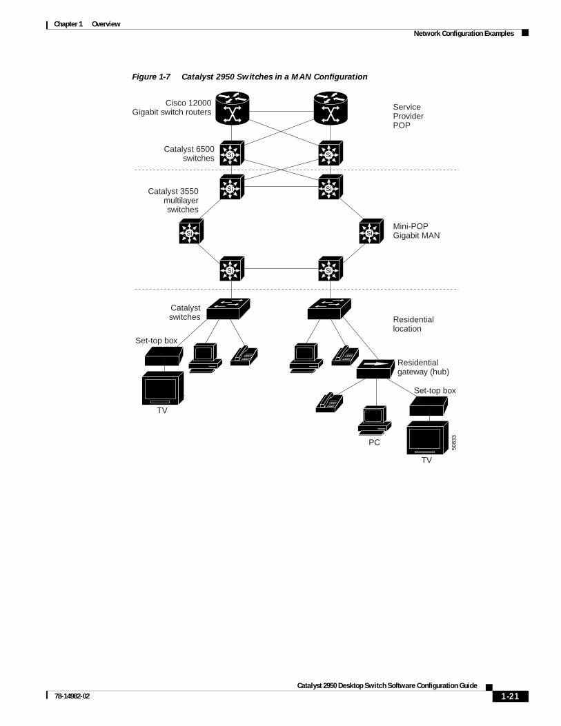
Multidwelling Network Using Catalyst 2950 SwitchesA growing segment of residential and commercial customers are requiring high-speed access to Ethernet metropolitan-area networks (MANs). Figure 1-7 shows a configuration for a Gigabit Ethernet MAN ring using Catalyst 3550 multilayer switches as aggregation switches in the mini-point-of-presence (POP) location. These switches are connected through 1000BASE-X GBIC ports.
The resident switches can be Catalyst 2950 switches, providing customers with high-speed connections to the MAN. Catalyst LRE Layer 2 only switches also can be used as residential switches for customers requiring connectivity through existing telephone lines. The Catalyst LRE switches can then be connected to another residential switch or to an aggregation switch. For more information about the LRE switches, refer to the Catalyst 2950 Desktop Switch Hardware Installation Guide.
All ports on the residential Catalyst 2950 switches (and Catalyst LRE switches if they are included) are configured as 802.1Q trunks with protected port and STP root guard features enabled. The protected port feature provides security and isolation between ports on the switch, ensuring that subscribers cannot view packets destined for other subscribers. STP root guard prevents unauthorized devices from becoming the STP root switch. All ports have IGMP snooping or CGMP enabled for multicast traffic management. ACLs on the uplink ports to the aggregating Catalyst 3550 multilayer switches provide security and bandwidth management.
The aggregating switches and routers provide services such as those described in the previous examples, “Small to Medium-Sized Network Configuration” and “Large Campus Configuration.”
Cisco 576LRE 997
POTS telephones
POTSsplitter
POTSsplitter
Laptop
Cisco router7500
Central officeCopper twisted pair
Offices and users
8938
0
Requiredmicrofilter
Building 1
Building 2
Building 3
Building 4
Catalyst 2950ST-24LRE 997 switches(DC-input power)
Cisco 576 LRE 997 CPE
1-20Catalyst 2950 Desktop Switch Software Configuration Guide
78-14982-02
Chapter 1 OverviewNetwork Configuration Examples
Figure 1-7 Catalyst 2950 Switches in a MAN Configuration
5083
3
ServiceProviderPOP
Mini-POPGigabit MAN
Residentiallocation
Catalyst 3550multilayerswitches
Catalystswitches
Catalyst 6500switches
Cisco 12000Gigabit switch routers
Si Si
Si Si
Si Si
SiSi
Residentialgateway (hub)
Set-top box
TV
PC
Set-top box
TV
1-21Catalyst 2950 Desktop Switch Software Configuration Guide
78-14982-02
Chapter 1 OverviewNetwork Configuration Examples
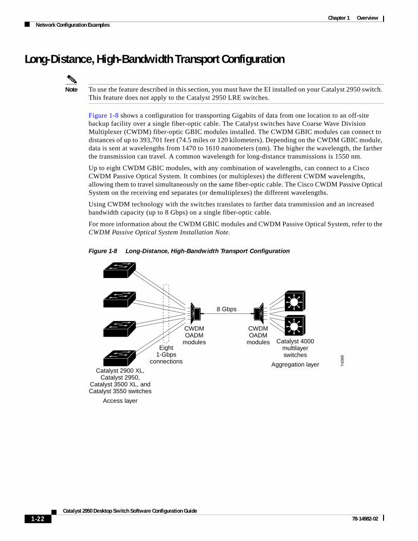
Long-Distance, High-Bandwidth Transport Configuration
Note To use the feature described in this section, you must have the EI installed on your Catalyst 2950 switch. This feature does not apply to the Catalyst 2950 LRE switches.
Figure 1-8 shows a configuration for transporting Gigabits of data from one location to an off-site backup facility over a single fiber-optic cable. The Catalyst switches have Coarse Wave Division Multiplexer (CWDM) fiber-optic GBIC modules installed. The CWDM GBIC modules can connect to distances of up to 393,701 feet (74.5 miles or 120 kilometers). Depending on the CWDM GBIC module, data is sent at wavelengths from 1470 to 1610 nanometers (nm). The higher the wavelength, the farther the transmission can travel. A common wavelength for long-distance transmissions is 1550 nm.
Up to eight CWDM GBIC modules, with any combination of wavelengths, can connect to a Cisco CWDM Passive Optical System. It combines (or multiplexes) the different CWDM wavelengths, allowing them to travel simultaneously on the same fiber-optic cable. The Cisco CWDM Passive Optical System on the receiving end separates (or demultiplexes) the different wavelengths.
Using CWDM technology with the switches translates to farther data transmission and an increased bandwidth capacity (up to 8 Gbps) on a single fiber-optic cable.
For more information about the CWDM GBIC modules and CWDM Passive Optical System, refer to the CWDM Passive Optical System Installation Note.
Figure 1-8 Long-Distance, High-Bandwidth Transport Configuration
7408
9
Catalyst 2900 XL,Catalyst 2950,
Catalyst 3500 XL, andCatalyst 3550 switches
Access layer
Catalyst 4000multilayerswitches
Aggregation layer
Eight1-Gbps
connections
8 Gbps
CWDMOADM
modules
CWDMOADM
modules
1-22Catalyst 2950 Desktop Switch Software Configuration Guide
78-14982-02
Chapter 1 OverviewWhere to Go Next
Where to Go NextBefore configuring the switch, review these sections for start up information:
• Chapter 2, “Using the Command-Line Interface”
• Chapter 3, “Getting Started with CMS”
• Chapter 4, “Assigning the Switch IP Address and Default Gateway”
• Chapter 5, “Configuring IE2100 CNS Agents”
1-23Catalyst 2950 Desktop Switch Software Configuration Guide
78-14982-02

Chapter 1 OverviewWhere to Go Next
1-24Catalyst 2950 Desktop Switch Software Configuration Guide
78-14982-02