Embed Size (px)
Citation preview
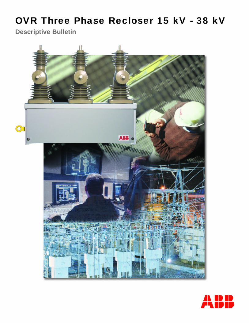
OVR Three Phase Recloser 15 kV - 38 kVDescriptive Bulletin

OVROVRImproving Distribution SystemReliability Through:
• Reliable Products by Design
• Innovative Protection and Automation Schemes
• Excellent Customer Support
Always a Generation Ahead
ABB continually strives to bring customers the latest technological advancesand superior performance. This is especially true of our feeder automationproduct line, where we are able to leverage our knowledge, experience andR&D through a common set of building blocks. These building blocks giveour customers modularity and flexibility to obtain a product for today'srequirements, while allowing for future upgrades. The ABB OVR recloser isable to meet present recloser demands, plus offer advanced capabilities suchas fault location, adaptive protection, control monitoring, power quality,communications, single phase tripping and loop control for tomorrow’sneeds.
2

Industry RegulatorsIndustry regulators, or Public Utility Commissions, are increasinglyconsidering performance-based regulation mechanisms, whichexplicitly state reliability penalty targets. These regulatory commissions are monitoring several indices such as:
• System Average Interruption Frequency (SAIFI)• System Average Interruption Duration (SAIDI)• Momentary Average Interruption Frequency (MAIFI).
These indices are accompanied by financial bonuses or penaltiesthat directly impact the utility's bottom line.
Utilities are receiving pressure to improve reliability from three stakeholders:
• customers• industry regulators• company owners
CustomersCustomers expect a level of reliability equal to, orbetter than, the reliability they have had.Furthermore, an increasing number of customersare operating businesses, which are sensitive to reliability and service quality.
3
Improved Distribution System Reliability
Conventional methods for improving system reliability include tree trimming, animal guards,lightening protection, and maintaining problem circuits. However, many of today’s utilities aremoving toward specialized system configurations, such as midpoint reclosers, tie reclosers, loopconfigurations, and single phase reclosing to improve reliability. These configurations, combined with remote communication, can substantially improve reliability indices, subsequently enhancing customer service and maximizing shareholder value.
Company OwnersShareholders or company owners expect suitable rates of return. All capital, operationaland maintenance expenditures are selected tomaximize results.

4
Benefits of High Voltage UnitBenefits of High Voltage Unit• Compact, lightweight design for easy installation
• Superior life - rated for 10,000 operations
• Environmentally friendly - no oil or gas
• HCEP encapsulating material reduces weathering erosion and outdoor aging, improving life expectancy
• Vacuum interruption for maximum reliability and minimum maintenance
• Magnetic actuation with fewer moving parts and less maintenance
• Stainless steel enclosure to prevent corrosion in harsh environments
Reliability by Design
15 kV
27 kV
38 kV

5
Reliability by Design
Benefits of Control UnitBenefits of Control Unit• Simple, menu-driven programming for easy use
• Hot line tagging feature on faceplate for simple and safe operation
• Easy access front RS-232 port
• Button on front panel (Counters) for easy access to operational data
• Over 50 protection curves and 3 user programmable curves for superior coordination
• Single phase tripping option reduces outages
• Optional loop control module for fast restoration of distribution systems
• Fault location reduces outage time
• Convenient GFI receptacle for powering laptop
• Power quality software records voltage sags, swells and interruptions
• 304 stainless steel enclosure prevents corrosion in harsh environments
• Ample space for mounting communications equipmentto save installation time and money
• UPS module allows wide range of control voltage input (85 - 265 VAC/DC)

6
Pole assembly– Resistant to vandalization– Maintenance free: tested to 10,000 mechanical operations
without degradation– Few moving parts– High creepage pole design (38 inches to ground)– Easy to replace individual poles– Superior HCEP encapsulating material for outdoor
applications
Insulating material– Advanced epoxy (HCEP) encapsulating material– Light weight for easy handling– Increased weather durability and improved aging– Improved performance in heavily polluted areas
Vacuum interrupters– Maximum reliability– Design ensures superior contact wear and long life– Superior life: 10,000 load operations– Minimal maintenance– Environmentally friendly
Integrated sensors– Provides required signals for current protection, metering
and data gathering– Sized for superior response up to the full-rated fault
current– Reliable and accurate data for waveform analysis– One sensor per phase
Mechanical trip– Pulling yellow handle down will mechanically open all
three poles of the OVR unit– Lockout function is conveniently performed using the
available hot-line tagging switch on the OVR control unit– Optional close block feature for manual trip
Reliability by Design

7
Position switch– One per pole– Determines pole open or closed positions– Allows independent pole operation– Provides positive pole position feedback to the OVR
control unit– Double break, galvanically separate contacts– Self-cleaning contact points by wiping action– Gold contacts for low currents and voltages at low contact
transfer– Transparent green housing allows the contact position
and internal mechanism to be easily viewed
Magnetic actuators– Increased reliability - rated to 10,000 operations– Simple design– Bi-stable - no power required to hold contacts open or
closed– Few moving parts mean low maintenance and high
reliability– Three individual actuators eliminate complicated linkages
Outdoor cabinet– 304 stainless steel enclosure prevents corrosion– Eliminates environmental and maintenance concerns
of oil or gas– Option for up to six voltage inputs into the high
voltage cabinet eliminates the need to run cables to thelow voltage cabinet
– Shunt resistors allow for disconnecting control cable without open circuiting current sensors
Open/Close indicators (on bottom)– Individual phase position indicators– Highly visible from the ground– Large and easy to view– Open/close symbols– Reflective so the position can be seen at night with a
flashlight
Reliability by Design

8
Reliability by Design
3D Modeling: Advanced Design Technology
Advances in simulation software allow for the virtual design and testing of poles andactuators prior to any actual manufacturing and testing. This gives ABB the ability touse 3D electrostatic modeling on the poles to design improvements, minimize partialdischarge and construct dielectrically robust poles. This design process minimizes therisk of field failures over the life of the product.
Innovative Pole DesignInnovative Pole DesignLeads to ReliabilityLeads to Reliability
• Improved Interrupter
• Advanced Design Technology
• Cutting Edge Material
ABB Vacuum Interruption:Improved Interrupter
ABB has been developing and manufacturing vacuum interrupters since the early 1980's.Worldwide, more than one million ABB vacuuminterrupters are in service. ABB's vacuum interrupter facility uses the latest technologies inhigh quality mass production to produce the nextgeneration of vacuum interrupter. This new generation vacuum interrupter is robust for universal application.
Vacuum interrupters are compact, maintenance-free,with a long service life, and excellent environmentalcompatibility. Vacuum technology fits very well withthe recloser requirements since it can easily handlefrequent operations. Additionally, vacuum interrupters do not need any extra time to recover,so even the first reclosing operation (after 100-300msec) is not a problem.

9
Taking alead fromnature.
CEP HCEP
Design versatility + +
Manufacturing process + +
No. of interfaces + +
Animal attack + +
Hydrophobicity o +
Thermal shock resistance o +
Low flash-over probability o +
HCEP: Cutting Edge Insulating Material
The OVR insulating material is Hydrophobic Cycloaliphatic Epoxy(HCEP). HCEP is the next generation of Cycloaliphatic Epoxy(CEP).
Hydrophobicity means resistance to water. It is advantageous for outdoor applications because it prevents water from developing completely wetted, resistive conductive surfaces. Leakage currents aretherefore reduced, which helps to reduce the flashover risk. The resultis enhanced reliability. Furthermore, less discharge activity means lessattack and therefore less surface erosion, improving insulators’ lifeexpectancy.
Reliability by Design
+ = positiveo = neutralFrom CEP to HCEP
Advantages of HCEP over CEP
- Improved performance in heavily polluted areas- Improved weatherability and outdoor aging- Increased life expectancy- Enhanced reliability
Why do we need Hydrophobicity?
- Improved water beading and runoff- Lower leakage currents- Less discharge activity- Lower flash-over probability- Less erosion- Better reliability- Improved life expectancy

10
Local human-machine interface– Enlarged LCD (1” x 5”) with large characters (two lines of 20 characters)– Simple menu-driven programming using large six-button keypad– Backlit display indicates metering values, fault information and location– Temperature compensated
Indicator lights– Continual self-checking with status indication– Pickup and lockout indication
Front panel pushbuttons– Remote or local selection between three setting groups: Primary, Alternate 1 (Alt 1) and
Alternate 2 (Alt 2)– Front panel button to set Alt 1 settings– Ground blocked, remote blocked, and reclose blocked pushbuttons– Sensitive Earth Fault (SEF) is optional, recommended for ungrounded or Delta CT applications– PROG 1 battery test feature preprogrammed– User programmable LEDs for alarms, additional targets, etc.– Counters button for easy access to number of operations and overcurrent trip information
Hot line tagging feature– On faceplate for simpler and safer operation– Can be mapped for multiple applications
Front mounted RS-232 port– Independent from rear mounted RS-232 port– Easy download and upload of data on-site using WinPCD
Separate open and close pushbuttons– Separate indicator light for easier viewing– ANSI or IEC coloring for individual practices
1
2
3
4
5
6
Reliability by Design
PCD Control Unit

11
Reliability by Design
1
2
3 4
5
6

12
Control cabinet– 304 stainless steel cabinet, NEMA 3R with drip shield– Battery provides full operational capability for 48+ hours– Ample space for mounting communications equipment– Single-point latching with padlockable handle – Vented design
GFI– Ground fault receptacle provides AC power for a laptop
Communication & I/O ports– Isolated RS-232 and RS-485 ports– ST fiber optic ports for interference-free communication; fiber optic
signals are fully regenerated at each unit for successful daisy chaining– Programmable I/O ports: 6 inputs, 4 outputs standard with UPS– Programmable I/O ports: 10 inputs, 7 outputs standard with PS– Field upgradeable to meet future communication requirements
Loop Control Module (optional)– Speeds restoration on distribution power systems– Reduces the number of outages– Compatible with the PCD– Isolates the faulted section– Sectionalizes or removes the faulted section from the
distribution system– Algorithm detects loss and restoration of voltage– Works in single and three phase mode– Includes direct access to alternate 2 settings– Ability to monitor/accept six voltage inputs
Single phase tripping (optional)– Reduces unnecessary three phase interruptions and
outages due to single phase faults– Single phase tripping options of only picked up phases (OPUP) or
one or all phases (OOAP)– Each step of reclose cycle can be individually configured
to single or three phase trip or lockout for optimum coordination
Oscillographic data– Storage capacity of 64 cycles of monitored waveform
data at 32 samples per cycle– All data can be downloaded on-site or remotely through
communication interfaces
Fault recording– Records last 128 operations of:
• phase and ground fault amperes• phase and ground voltage• tripping element• reclose time• distance to fault• estimated fault resistance • time stamp
– Stores 512 operation records
Loop Control Module
Control Cabinet
Reliability by Design
Oscillographic Data

13
Remote communications– RS-232 port includes RTS/CTS handshaking– Modbus ASCII and RTU, and DNP 3.0TM protocols included with all units– DNP 3.0TM is compliant to Level 2
Fault location*– Patented algorithm estimates fault impedance and computes apparent distance to fault – Works in background mode to maintain protection integrity*requires homogeneous distribution line, three phase voltage source, and does not apply in single phase tripping mode
Power quality**– Records voltage sags, swells and interruptions– Implemented per ANSI/IEEE Std. 1159 and includes programmable voltage thresholds– Triggers oscillographic capture**three phase voltage source required
Metering – Meters current and voltage (with voltage input supplied) to ±1% accuracy– Measures kW and kVARh, power factor, demand Watts and VARs, and frequency to ±2% accuracy– User-selectable load profile data sampling 5, 15, 30, 60 minute time internal which will contain 13.3, 40, 80
or 160 days of information– All data can be downloaded on-site or remotely through communications interface
Protective functions – Phase time overcurrent protection (51P)– Phase instantaneous overcurrent protection (50P-1)– Two definite time overcurrent settings (50P-2, 50P-3)– Ground overcurrent protection (51N)– Ground instantaneous overcurrent protection (50N-1)– Two definite time ground overcurrent settings (50N-2, 50N-3)– Negative sequence overcurrent protection (46)– Phase and ground directional overcurrent protection (67P, 67N)– Two independent steps for load shed, restoration, and over-frequency (81S, 81R, 81O)– Undervoltage and overvoltage control and alarm (27/59)– Up to four reclose cycles (define a recloser cycle 79-1 --> 79-5) close four times / trip five– Adaptive reclosing shots: each reclose sequence allows independent programming
of protective functions– Sensitive Earth Fault protection with directional features (optional)– Available with up to 38 recloser curves, nine ANSI curves, four IEC curves and three user
programmable curves
Adaptive protection– Three independent protection groups– Zone sequence coordination– Cold load pick-up– Reverse power reconfiguration (32P, 32N)
Reliability by Design

14
Innovation Protection & Automation Schemes
Case 1: Typical DistributionLine (with reclosing relay)SAIDI: 3.3 hrs/yrSAIFI: 1.6 int/cust/yrMAIFI: 8.7 mom/yr
Case 2: Three Phase Midpoint Recloser without Single Phase TrippingSAIDI: 2.6 hrs/yr (21% reduction)SAIFI: 1.2 int/cust/yr (25% reduction)MAIFI: 6.5 mom/yr (25% reduction)
Three Phase Midpoint Recloser with Single Phase TrippingSAIDI: 2.3 hrs/yr (30% reduction)SAIFI: 1.1 int/cust/yr (31% reduction)MAIFI: 5.4 mom/yr (38% reduction)
In today's utility environment, distribution system reliability is becoming more important. There are severalindices developed for reliability of service that utilities account for and track. These indices include SystemAverage Interruption Frequency Index (SAIDI), System Average Interruption Duration (SAIDI), andMomentary Average Interruption Frequency Index (MAIFI). Currently, most utilities are measured by the PublicUtilities Commission to assure they meet a minimum requirement with respect to these indices. These measurements are being utilized to assess penalty/performance-based rates at the utilities, making it is necessaryto achieve higher reliability. Below are some examples of how current technology can improve reliability andreduce system outages.
Substation
Substation
10 Miles 1,800 Customers
5 Miles 5 Miles
Recloser
Recloser Recloser
Single Phase Tripping
The OVR recloser is the first of its kind in the industry. It includes fast acting, maintenance free, independent-pole, magnetic actuation instead of a ganged-pole mechanism. The single phase tripping option is flexible bydesign in order to meet virtually all current and future customer needs.
The three global modes available are:
1. Three phase tripping
2. Single phase tripping OPUP (only picked up phases trip)
3. Single phase tripping OOAP (one or all phases trip)
Each step of the reclose cycle can be individually configured to single or three phase trip to lockout for each ofthe protective functions. Two common examples would be:
1. The recloser is set to trip on single phase and lockout on all three phases if fault is permanent.
2. The recloser is set up to both trip and lockout on single phase.
˜̃

15
Innovation Protection & Automation Schemes
Case 3: Loop Configuration without Single Phase TrippingSAIDI: 2.1 hrs/yr (36% reduction)SAIFI: 1.0 int/cust/yr (37% reduction)MAIFI: 6.8 mom/yr (22% reduction)
Loop Configuration with Single Phase TrippingSAIDI: 1.8 hrs/yr (45% reduction)SAIFI: 0.8 int/cust/yr (50% reduction)MAIFI: 3.1 mom/yr (64% reduction)
Loop Control
ABB's Loop Control Module (LCM) is completely compatible with the PCD. The LCM detectseither normal voltage or loss of voltage, from one or two sources. It initiates preprogrammed logical steps to isolate the faulted section, depending upon the voltage configuration and feederlocation.
The LCM provides a loop control function to sectionalize or remove the faulted section from thedistribution system. This control module provides sectionalizing control of either a recloser or aswitch, and restores the distribution system by closing the tie-point recloser from another electricalsource.
The LCM allows individual reclosers to act as a sectionalizer, midpoint or tie, without physical con-nections to other reclosers, allowing it to be installed in existing feeder automation systems.
Application Summary
The OVR's feature sets are well-suited for these specialty applications. Through the use of singlephase tripping and loop control schemes, utilities can reduce their yearly outage time up to 45%.
Substation
Substation
Breaker
Breaker N.C.Recloser
N.C.Recloser
N.O.Recloser
5 Miles 5 Miles

Excellent Customer Support
16
OVROVRCustomer Support:• Free 24-7 technical support
line
• Feeder Automation Users website features:
- News
- Frequently Asked Questions
- Discussion Board
- Technical Information
- Product Brochures
- Software Downloads
- Contact Information
- Instruction Manuals
- Programming Shortcuts
- Drawings
• Training
- Multi-Track Factory Based Training
• Lineman Track
• Engineering Track
- Multi-Track Field Based Training
• Lineman Track
• Engineering Track
- Mobile Training Aids
• Unique tool incorporates a complete VR-3S and PCD with the LCM and simulates loop schemes using four PCDs with LCMs tovisually demonstrate the schemes. Simulation can be tailored to customer specific schemes to provide the greatest benefit.
- PCD Training Aids with Simulators
• Includes a PCD with a simulator box
• Enables tabletop practice and simulation of the PCD
• Three Year Warranty

Technical Data
17
OVR ratingsNom. operating voltage: 2.4-14.4 24.9 34.5 kVMax. design voltage: 15.5 27 38 kVMax. continuous current: 630/800* 630/800* 630/800* AMax. interrupting current: 12.5 12.5 12.5 kA BIL: 110/125* 125 170 kV Dry withstand 60 Hz 1 Min.: 50 60 70 kVWet withstand 60 Hz 10 Sec.: 45 50 55 kVPhase Spacing: 15.50 (394) 15.50 (394) 15.50 (394) inches (mm)External creep distance, H2-ground: 38.00 (960) 38.00 (960) 50.70 (1288) inches (mm)External creep distance, H1-H2: 45.00 (1160) 45.00 (1160) 49.8 (1260) inches (mm)Min. external strike distance: 9.5 (240) 9.5 (240) 14.4 (367) inches (mm)Max. interrupting time: 0.040 0.040 0.040 sec maxMax. closing time: 0.060 0.060 0.060 sec maxMaterials: Vacuum interrupter encapsulated in hydrophobic cycloaliphatic epoxy with 304 stainless steel cabinets Current sensors: One per phase encapsulated into the poleOperating temperature: -40° to +70° CControl voltage: 85 - 265 VAC-DC with UPS; 24, 48, 125, 250 VDC with PSUpper unit weight: 325 325 400 lbsLower unit weight: 150 150 150 lbs
Battery• Sealed lead acid rechargeable battery pack• Monitor locally and remotely• Easily accessible for changing• Allows for 48+ hour carryover and multiple operations upon loss of power• Includes capacitor backup for battery assistance
Summary specificationsAccuracy: Voltage: ± 1% accuracy
Current: ± 1% accuracy Load profile data (requires voltage input):
kWh and kVARh (± 2% accuracy)Power FactorDemand Watts and VARsFrequency
OVR testingANSI: Meets all applicable recloser standards (ANSI 37.60, IEEE, IEC and NEMA)Life test: 10,000 mechanical operations without degradation
PCD testingTransient Immunity:
• Surge Withstand Capability: SWC and fast transient tests per ANSI C37.90.l and IEC 255-22-1 class III and 255-22-4 class IV for all connections except comm ports
• Isolated comm ports per ANSI 37.90.1 using oscillatory SWC Test Wave only, and per IEC 255-22-1 class III• EMI test per ANSI C37.90.2
* available optional ratings

18
Pole Mounted DimensionsA B C D E F G H
15 & 27 kV in 49.82 41.75 15.50 11.10 28.04 38.01 25.30 15.44mm 1265.45 1060.45 393.70 282.05 712.26 965.51 642.71 392.14
38 kV in 49.82 41.75 15.50 12.30 28.04 44.00 29.80 15.44mm 1265.45 1060.45 393.70 314.00 712.26 1119.00 759.00 392.14

19
Substation Mounted DimensionsB C D L M N O P Q R
15 & 27 kV in 42.06 15.50 11.10 95.80 65.60 48.00 52.38 22.00 29.06 27.90mm 1068.19 393.70 282.05 2433.32 1666.00 1219.20 1330.45 558.80 738.17 708.62
38 kV in 42.06 15.50 12.30 95.80 65.60 48.00 52.38 22.00 29.06 34.90mm 1068.19 393.70 314.00 2433.32 1666.00 1219.20 1330.45 558.80 738.17 888.62

ABB Inc.655 Century PointLake Mary, FL 32746 U.S.A.For sales & marketing contact your localrepresentative or:Tel: +1-407-732-2000
1-800-929-7947 Fax: +1-407-732-2161www.abb.com/mediumvoltage