Embed Size (px)
Citation preview

USC
Owner & Assembly ManualAmerica’s Best Tan™
Owner & Assembly Manual™
Owner & Assembly Manual 2M and Sundazzler™
Owner & Assembly Manual™
Owner & Assembly Manual 2M and Sundazzler™ 2M and Sundazzler
Les Spécifications Françaises Enclos
4251 N.E. Port Drive • Lee’s Summit, MO 64064 • 800-554-8268
www.heartlandtan.comPart #94052 11/05

2
Table of Contents
3 . . . . . . . . . . . Welcome
4 - 6 . . . . . . . . 2m™ Specifications/Exposure Schedule
7 - 9 . . . . . . . . Sundazzler™ Specifications/Exposure Schedule
10 . . . . . . . . . . Warnings and Cautions
11 . . . . . . . . . . Care and Cleaning
12 - 19 . . . . . . Timer System
20 - 23 . . . . . . Assembly Instructions
24 - 29 . . . . . . Wiring Diagrams
30 - 34 . . . . . . 30 - 34 . . . . . . 30 - 34 Changing Room Assembly Instructions
35 . . . . . . . . . . Limited Warranty

3
Welcome
Dear Valued Customer:
Congratulations! You have just purchased one of the finest pieces of tanning equipment available to the indoor tanning industry. We at Heartland Tanning, Inc. sincerely appreciate your business.
The 2M, Sundazzler™ tanning booths are manufactured right here in the heart of our country. Our tanning booths are constructed of 12GAUGE solid steel and is designed to hold up under heavy use. We have confidence in our manufactured products and that is why our equipment is backed by Heartland’s unprecedented 5 year limited warranty. Designed to be user friendly, the 2M and Sundazzler™by Heartland’s unprecedented 5 year limited warranty. Designed to be user friendly, the 2M and
™by Heartland’s unprecedented 5 year limited warranty. Designed to be user friendly, the 2M and
are easy to assemble and maintain.
Please read your owner & assembly manual thoroughtly prior to the first use of your new tanning booth.
Heartland Tanning, Inc.4251 N.E. Port DriveLee’s Summit, MO 640641-800-554-8268
NOTICE: Any misuse, abuse, modifications, alteration, improper installation, etc. of this product or its intended use will subject said party to direct responsibility for any and all consequences result-ing from such action. Furthermore, such actions will void all warranties and may relieve Heartland
Tanning, Inc. of any liabilities relating to said product.
4
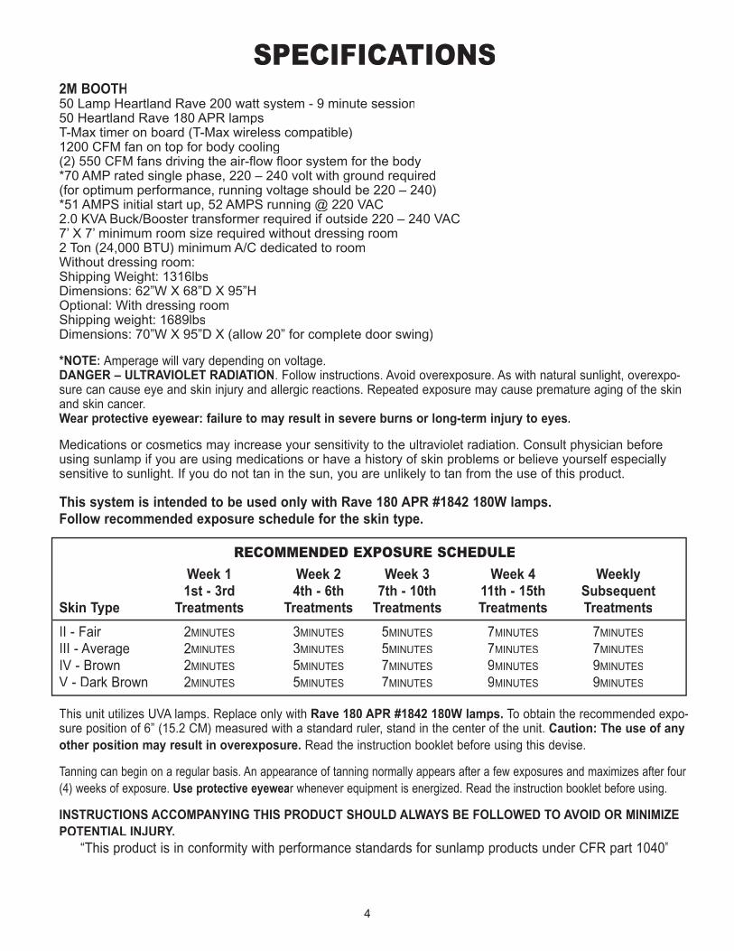
SPECIFICATIONS2M BOOTH50 Lamp Heartland Rave 200 watt system - 9 minute session50 Heartland Rave 180 APR lampsT-Max timer on board (T-Max wireless compatible)1200 CFM fan on top for body cooling(2) 550 CFM fans driving the air-fl ow fl oor system for the body*70 AMP rated single phase, 220 – 240 volt with ground required(for optimum performance, running voltage should be 220 – 240)*51 AMPS initial start up, 52 AMPS running @ 220 VAC2.0 KVA Buck/Booster transformer required if outside 220 – 240 VAC7’ X 7’ minimum room size required without dressing room2 Ton (24,000 BTU) minimum A/C dedicated to roomWithout dressing room: Shipping Weight: 1316lbsDimensions: 62”W X 68”D X 95”HOptional: With dressing roomShipping weight: 1689lbsDimensions: 70”W X 95”D X (allow 20” for complete door swing)
*NOTE: Amperage will vary depending on voltage.DANGER – ULTRAVIOLET RADIATION. Follow instructions. Avoid overexposure. As with natural sunlight, overexpo-sure can cause eye and skin injury and allergic reactions. Repeated exposure may cause premature aging of the skin and skin cancer. Wear protective eyewear: failure to may result in severe burns or long-term injury to eyes.
Medications or cosmetics may increase your sensitivity to the ultraviolet radiation. Consult physician before using sunlamp if you are using medications or have a history of skin problems or believe yourself especially sensitive to sunlight. If you do not tan in the sun, you are unlikely to tan from the use of this product.
This system is intended to be used only with Rave 180 APR #1842 180W lamps. Follow recommended exposure schedule for the skin type.
RECOMMENDED EXPOSURE SCHEDULE
Week 1 Week 2 Week 3 Week 4 Weekly 1st - 3rd 4th - 6th 7th - 10th 11th - 15th SubsequentSkin Type Treatments Treatments Treatments Treatments Treatments
II - Fair 2MINUTES 3MINUTES 5MINUTES 7MINUTES 7MINUTES
III - Average 2MINUTES 3MINUTES 5MINUTES 7MINUTES 7MINUTES
IV - Brown 2MINUTES 5MINUTES 7MINUTES 9MINUTES 9MINUTES
V - Dark Brown 2MINUTES 5MINUTES 7MINUTES 9MINUTES 9MINUTES
This unit utilizes UVA lamps. Replace only with Rave 180 APR #1842 180W lamps. To obtain the recommended expo-sure position of 6” (15.2 CM) measured with a standard ruler, stand in the center of the unit. Caution: The use of any other position may result in overexposure. Read the instruction booklet before using this devise.
Tanning can begin on a regular basis. An appearance of tanning normally appears after a few exposures and maximizes after four (4) weeks of exposure. Use protective eyewear whenever equipment is energized. Read the instruction booklet before using.
INSTRUCTIONS ACCOMPANYING THIS PRODUCT SHOULD ALWAYS BE FOLLOWED TO AVOID OR MINIMIZE POTENTIAL INJURY.
“This product is in conformity with performance standards for sunlamp products under CFR part 1040”
5
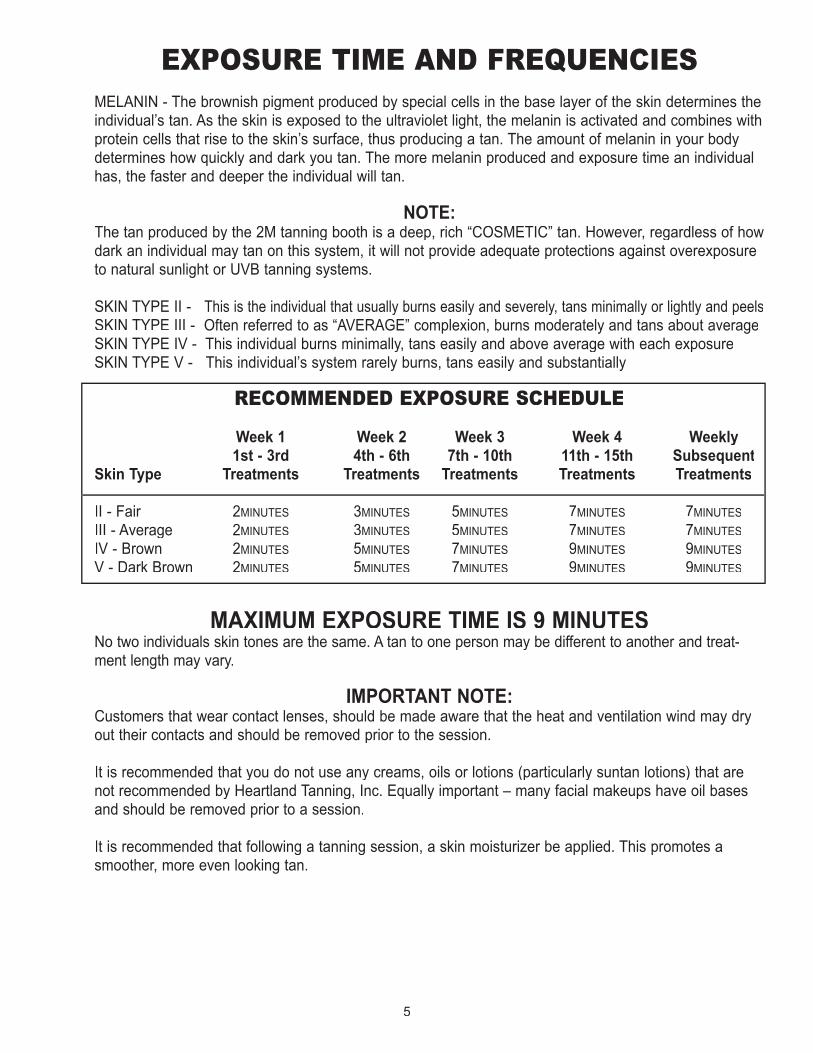
EXPOSURE TIME AND FREQUENCIESMELANIN - The brownish pigment produced by special cells in the base layer of the skin determines the individual’s tan. As the skin is exposed to the ultraviolet light, the melanin is activated and combines with protein cells that rise to the skin’s surface, thus producing a tan. The amount of melanin in your body determines how quickly and dark you tan. The more melanin produced and exposure time an individual has, the faster and deeper the individual will tan.
NOTE: The tan produced by the 2M tanning booth is a deep, rich “COSMETIC” tan. However, regardless of how dark an individual may tan on this system, it will not provide adequate protections against overexposure to natural sunlight or UVB tanning systems.
SKIN TYPE II - This is the individual that usually burns easily and severely, tans minimally or lightly and peelsSKIN TYPE III - Often referred to as “AVERAGE” complexion, burns moderately and tans about averageSKIN TYPE IV - This individual burns minimally, tans easily and above average with each exposureSKIN TYPE V - This individual’s system rarely burns, tans easily and substantially
RECOMMENDED EXPOSURE SCHEDULE
Week 1 Week 2 Week 3 Week 4 Weekly 1st - 3rd 4th - 6th 7th - 10th 11th - 15th SubsequentSkin Type Treatments Treatments Treatments Treatments Treatments
II - Fair 2MINUTES 3MINUTES 5MINUTES 7MINUTES 7MINUTES
III - Average 2MINUTES 3MINUTES 5MINUTES 7MINUTES 7MINUTES
IV - Brown 2MINUTES 5MINUTES 7MINUTES 9MINUTES 9MINUTES
V - Dark Brown 2MINUTES 5MINUTES 7MINUTES 9MINUTES 9MINUTES
MAXIMUM EXPOSURE TIME IS 9 MINUTES No two individuals skin tones are the same. A tan to one person may be different to another and treat-ment length may vary.
IMPORTANT NOTE: Customers that wear contact lenses, should be made aware that the heat and ventilation wind may dry out their contacts and should be removed prior to the session.
It is recommended that you do not use any creams, oils or lotions (particularly suntan lotions) that are not recommended by Heartland Tanning, Inc. Equally important – many facial makeups have oil bases and should be removed prior to a session.
It is recommended that following a tanning session, a skin moisturizer be applied. This promotes a smoother, more even looking tan.

6
Caractéristiques2M BOOTHlongueur : 60 pouces de largeur par 54 pouces de profondeurhauteur : 95 poucespoids d’expédition : 1316 livresnombre de lampes : 50Voltage Recommande: 230 - 240aspiration électrique : 52 ampères à 220 volts*circuit requis : 220 volts, 2 poteau, briseur de de 60 ampères
*NOTE: Amperage will vary depending on voltage.DANGER – RAYONNEMENT ULTRAVIOLET. Suivez les instructions. Évitez la surexposition. Comme avec les rayons naturels du soleil, la surexposition peut causer dommage aux yeux et à la peau et des réactions allergiques. L’exposition répétée peut causer le vieillissement prématuré de la peau et du cancer de la peau. Portez des lunettes protectrices; le non-respect de cette consigne peut entraî-ter de graves brûlures ou des lésions oculaires à long terme.
Les médicaments ou les produits de beauté peuvent augmenter votre sensibilité au rayonnement ultra-violet. Consultez un médecin avant d’utiliser la lampe solaire si vous utilisez des médicaments ou avez une histoire des problèmes de peau ou croyez-vous particulièrement sensibles aux rayons du soleil. Si vous ne bronzez pas au soleil, il est peu probable que vous bronzerez avec l’utilisation de ce produit.
Questions au sujet des ventes ou de service : Heartland Tanning, Inc. • Lee’s Summit, MO – 1-800-554-8268
Suivez le programme recommandé d’exposition pour le type de peau.
Cette appareil utilise des lampes de l’ultra-violet A. Remplacez seulement avec les lampes de marque Rave 180 APR #1842 180W. La position minimum d’exposition est à 0,5 pouces 1,27 cm) de la sur-face de la lampe (instituez par le manufacturier). Lisez le livret d’instruction avant d’utiliser ce dis-positif. Pour utiliser, couchez-vous sous l’écran et abaissez dans la mesure où le réglage laissera. ATTENTION : L’UTILISATION DE N’IMPORTE QUELLE AUTRE POSITION PEUT AVOIR COMME CONSÉQUENCE LA SUREXPOSITION.
Le bronzage peut commencer de façon régulière. Un aspect de bronzage normalement apparaît après quelques expositions et atteint son niveau maximal après quatre (4) semaines d’exposition. Utilisez des lunettes protec-
Horaire d’exposition recommandé Semaine 1 Semaine 2 Semaine 3 Semaine 4 BihebdomadaireType de peau 1er – 3e 4e – 6e 7e – 10e 11e – 15e Traitements Traitements Traitements Traitements Traitements subséquentsType de peau 1er – 3e 4e – 6e 7e – 10e 11e – 15e Traitements Traitements Traitements Traitements Traitements subséquentsType de peau 1er – 3e 4e – 6e 7e – 10e 11e – 15e Traitements
II – Claire 2 MINUTES 3 MINUTES 5 MINUTES 7 MINUTES 7 MINUTESIII – Moyen 2 MINUTES 3 MINUTES 5 MINUTES 7 MINUTES 7 MINUTESIV – Foncé 2 MINUTES 5 MINUTES 7 MINUTES 9 MINUTES 9 MINUTESV – Très foncé 2 MINUTES 5 MINUTES 7 MINUTES 9 MINUTES 9 MINUTES
LE TEMPS MAXIMUM D’EXPOSITION EST DE 9 MINUTESCe produit est conforme aux normes de rendement pour des produits de lampe
de soleil tel que stipule la partie 1040 du document CFR 21.
Semaine 1 Semaine 2 Semaine 3 Semaine 4 BihebdomadaireType de peau 1er – 3e 4e – 6e 7e – 10e 11e – 15e Traitements Traitements Traitements Traitements Traitements subséquentsType de peau 1er – 3e 4e – 6e 7e – 10e 11e – 15e Traitements Traitements Traitements Traitements Traitements subséquentsType de peau 1er – 3e 4e – 6e 7e – 10e 11e – 15e Traitements
II – Claire 2 MINUTES 3 MINUTES 5 MINUTES 7 MINUTES 7 MINUTESIII – Moyen 2 MINUTES 3 MINUTES 5 MINUTES 7 MINUTES 7 MINUTESIV – Foncé 2 MINUTES 5 MINUTES 7 MINUTES 9 MINUTES 9 MINUTES
2 MINUTES 5 MINUTES 7 MINUTES 9 MINUTES 9 MINUTES
7
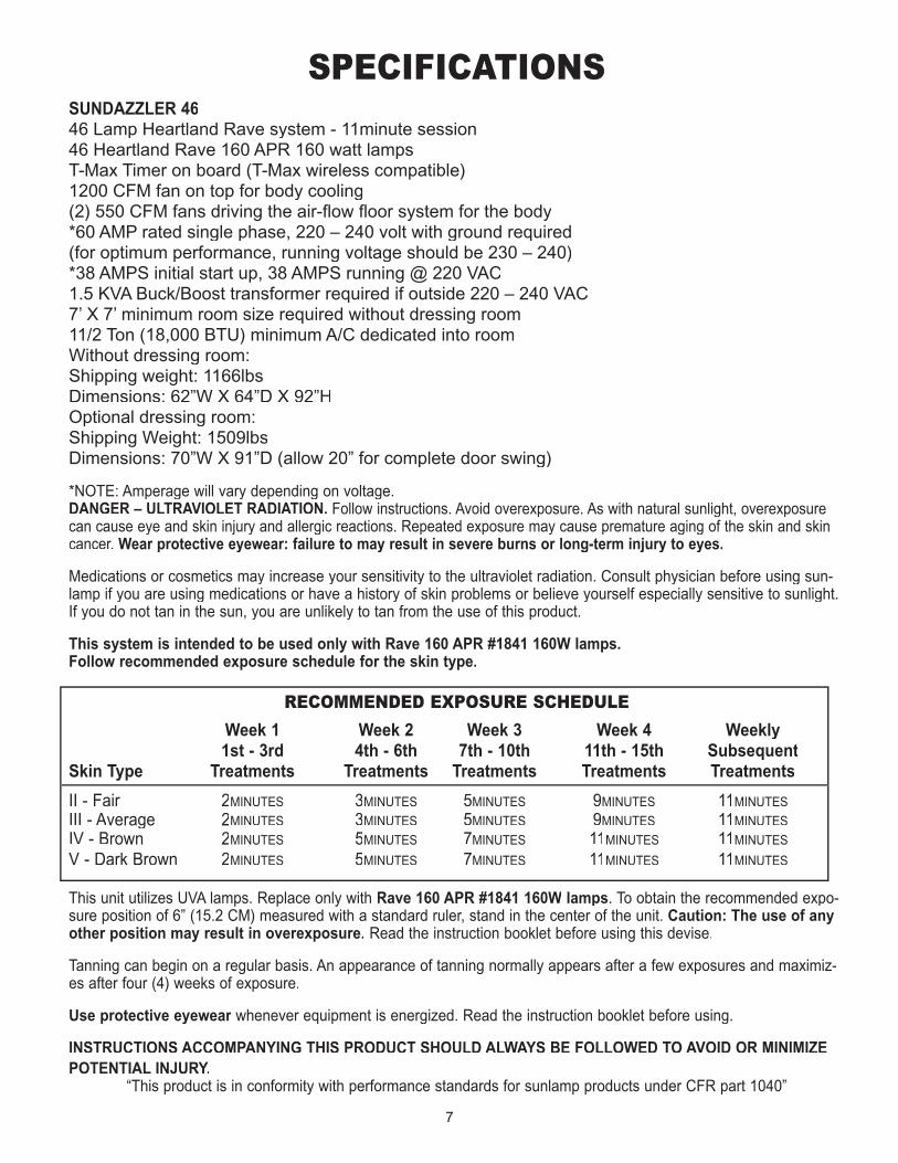
SPECIFICATIONSSUNDAZZLER 4646 Lamp Heartland Rave system - 11minute session46 Heartland Rave 160 APR 160 watt lampsT-Max Timer on board (T-Max wireless compatible)1200 CFM fan on top for body cooling(2) 550 CFM fans driving the air-fl ow fl oor system for the body*60 AMP rated single phase, 220 – 240 volt with ground required(for optimum performance, running voltage should be 230 – 240)*38 AMPS initial start up, 38 AMPS running @ 220 VAC1.5 KVA Buck/Boost transformer required if outside 220 – 240 VAC7’ X 7’ minimum room size required without dressing room11/2 Ton (18,000 BTU) minimum A/C dedicated into roomWithout dressing room:Shipping weight: 1166lbsDimensions: 62”W X 64”D X 92”HOptional dressing room: Shipping Weight: 1509lbsDimensions: 70”W X 91”D (allow 20” for complete door swing)
*NOTE: Amperage will vary depending on voltage.DANGER – ULTRAVIOLET RADIATION. Follow instructions. Avoid overexposure. As with natural sunlight, overexposure can cause eye and skin injury and allergic reactions. Repeated exposure may cause premature aging of the skin and skin cancer. Wear protective eyewear: failure to may result in severe burns or long-term injury to eyes.
Medications or cosmetics may increase your sensitivity to the ultraviolet radiation. Consult physician before using sun-lamp if you are using medications or have a history of skin problems or believe yourself especially sensitive to sunlight. If you do not tan in the sun, you are unlikely to tan from the use of this product.
This system is intended to be used only with Rave 160 APR #1841 160W lamps. Follow recommended exposure schedule for the skin type.
RECOMMENDED EXPOSURE SCHEDULE
Week 1 Week 2 Week 3 Week 4 Weekly 1st - 3rd 4th - 6th 7th - 10th 11th - 15th SubsequentSkin Type Treatments Treatments Treatments Treatments Treatments
II - Fair 2MINUTES 3MINUTES 5MINUTES 9MINUTES 11MINUTES
III - Average 2MINUTES 3MINUTES 5MINUTES 9MINUTES 11MINUTES
IV - Brown 2MINUTES 5MINUTES 7MINUTES 11MINUTES 11MINUTES
V - Dark Brown 2MINUTES 5MINUTES 7MINUTES 11MINUTES 11MINUTES
This unit utilizes UVA lamps. Replace only with Rave 160 APR #1841 160W lamps. To obtain the recommended expo-sure position of 6” (15.2 CM) measured with a standard ruler, stand in the center of the unit. Caution: The use of any other position may result in overexposure. Read the instruction booklet before using this devise.
Tanning can begin on a regular basis. An appearance of tanning normally appears after a few exposures and maximiz-es after four (4) weeks of exposure.
Use protective eyewear whenever equipment is energized. Read the instruction booklet before using.Use protective eyewear whenever equipment is energized. Read the instruction booklet before using.Use protective eyewear
INSTRUCTIONS ACCOMPANYING THIS PRODUCT SHOULD ALWAYS BE FOLLOWED TO AVOID OR MINIMIZE POTENTIAL INJURY.
“This product is in conformity with performance standards for sunlamp products under CFR part 1040”

8
EXPOSURE TIME AND FREQUENCIESMELANIN - The brownish pigment produced by special cells in the base layer of the skin determines the individ-ual’s tan. As the skin is exposed to the ultraviolet light, the melanin is activated and combines with protein cells that rise to the skin’s surface, thus producing a tan. The amount of melanin in your body determines how quickly and dark you tan. The more melanin produced and exposure time an individual has, the faster and deeper the individual will tan.
NOTE: The tan produced by the Sundazzler™ 46 is a deep, rich “COSMETIC” tan. However, regardless of how dark an individual may tan on this system, it will not provide adequate protections against overexposure to natural sunlight or UVB tanning systems.
SKIN TYPE II - This is the individual that usually burns easily and severely, tans minimally or lightly and peelsSKIN TYPE III - Often referred to as “AVERAGE” complexion, burns moderately and tans about averageSKIN TYPE IV - This individual burns minimally, tans easily and above average with each exposureSKIN TYPE V - This individual’s system rarely burns, tans easily and substantially
RECOMMENDED EXPOSURE SCHEDULE
Week 1 Week 2 Week 3 Week 4 Weekly 1st - 3rd 4th - 6th 7th - 10th 11th - 15th SubsequentSkin Type Treatments Treatments Treatments Treatments Treatments
II - Fair 2MINUTES 3MINUTES 5MINUTES 9MINUTES 11MINUTES
III - Average 2MINUTES 3MINUTES 5MINUTES 9MINUTES 11MINUTES
IV - Brown 2MINUTES 5MINUTES 7MINUTES 11MINUTES 11MINUTES
V - Dark Brown 2MINUTES 5MINUTES 7MINUTES 11MINUTES 11MINUTES
MAXIMUM EXPOSURE TIME IS 11 MINUTES No two individuals skin tones are the same. A tan to one person may be different to another and treatment length may vary.
IMPORTANT NOTE: Customers that wear contact lenses, should be made aware that the heat and ventilation wind may dry out their contacts and should be removed prior to the session.
It is recommended that you do not use any creams, oils or lotions (particularly suntan lotions) that are not rec-ommended by Heartland Tanning, Inc. Equally important – many facial makeups have oil bases and should be removed prior to a session.
It is recommended that following a tanning session, a skin moisturizer be applied. This promotes a smoother, more even looking tan.
9
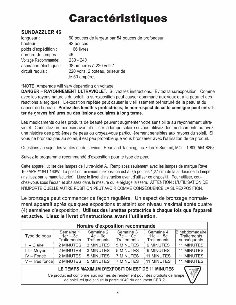
CaractéristiquesSUNDAZZLER 46longueur : 60 pouces de largeur par 54 pouces de profondeurhauteur : 92 poucespoids d’expédition : 1166 livresnombre de lampes : 46Voltage Recommande: 230 - 240aspiration électrique : 38 ampères à 220 volts*circuit requis : 220 volts, 2 poteau, briseur de de 50 ampères
*NOTE: Amperage will vary depending on voltage.DANGER – RAYONNEMENT ULTRAVIOLET. Suivez les instructions. Évitez la surexposition. Comme avec les rayons naturels du soleil, la surexposition peut causer dommage aux yeux et à la peau et des réactions allergiques. L’exposition répétée peut causer le vieillissement prématuré de la peau et du cancer de la peau. Portez des lunettes protectrices; le non-respect de cette consigne peut entraî-ter de graves brûlures ou des lésions oculaires à long terme.
Les médicaments ou les produits de beauté peuvent augmenter votre sensibilité au rayonnement ultra-violet. Consultez un médecin avant d’utiliser la lampe solaire si vous utilisez des médicaments ou avez une histoire des problèmes de peau ou croyez-vous particulièrement sensibles aux rayons du soleil. Si vous ne bronzez pas au soleil, il est peu probable que vous bronzerez avec l’utilisation de ce produit.
Questions au sujet des ventes ou de service : Heartland Tanning, Inc. • Lee’s Summit, MO – 1-800-554-8268
Suivez le programme recommandé d’exposition pour le type de peau.
Cette appareil utilise des lampes de l’ultra-violet A. Remplacez seulement avec les lampes de marque Rave 160 APR #1841 160W. La position minimum d’exposition est à 0,5 pouces 1,27 cm) de la surface de la lampe (instituez par le manufacturier). Lisez le livret d’instruction avant d’utiliser ce dispositif. Pour utiliser, cou-chez-vous sous l’écran et abaissez dans la mesure où le réglage laissera. ATTENTION : L’UTILISATION DE N’IMPORTE QUELLE AUTRE POSITION PEUT AVOIR COMME CONSÉQUENCE LA SUREXPOSITION.
Le bronzage peut commencer de façon régulière. Un aspect de bronzage normale-ment apparaît après quelques expositions et atteint son niveau maximal après quatre (4) semaines d’exposition. Utilisez des lunettes protectrice à chaque fois que l’appareil est active. Lisez le livret d’instructions avant l’utilisation.
Horaire d’exposition recommandé Semaine 1 Semaine 2 Semaine 3 Semaine 4 BihebdomadaireType de peau 1er – 3e 4e – 6e 7e – 10e 11e – 15e Traitements Traitements Traitements Traitements Traitements subséquentsType de peau 1er – 3e 4e – 6e 7e – 10e 11e – 15e Traitements Traitements Traitements Traitements Traitements subséquentsType de peau 1er – 3e 4e – 6e 7e – 10e 11e – 15e Traitements
II – Claire 2 MINUTES 3 MINUTES 5 MINUTES 9 MINUTES 11 MINUTESIII – Moyen 2 MINUTES 3 MINUTES 5 MINUTES 9 MINUTES 11 MINUTESIV – Foncé 2 MINUTES 5 MINUTES 7 MINUTES 11 MINUTES 11 MINUTESV – Très foncé 2 MINUTES 5 MINUTES 7 MINUTES 11 MINUTES 11 MINUTES
LE TEMPS MAXIMUM D’EXPOSITION EST DE 11 MINUTESCe produit est conforme aux normes de rendement pour des produits de lampe
de soleil tel que stipule la partie 1040 du document CFR 21.
Traitements Traitements Traitements Traitements subséquents Traitements Traitements Traitements Traitements subséquents
III – Moyen 2 MINUTES 3 MINUTES 5 MINUTES 9 MINUTES 11 MINUTESIII – Moyen 2 MINUTES 3 MINUTES 5 MINUTES 9 MINUTES 11 MINUTESIII – Moyen 2 MINUTES 3 MINUTES 5 MINUTES 9 MINUTES 11 MINUTES
Semaine 1 Semaine 2 Semaine 3 Semaine 4 BihebdomadaireType de peau 1er – 3e 4e – 6e 7e – 10e 11e – 15e Traitements Traitements Traitements Traitements Traitements subséquentsType de peau 1er – 3e 4e – 6e 7e – 10e 11e – 15e Traitements Traitements Traitements Traitements Traitements subséquentsType de peau 1er – 3e 4e – 6e 7e – 10e 11e – 15e Traitements Traitements Traitements Traitements Traitements subséquentsII – Claire 2 MINUTES 3 MINUTES 5 MINUTES 9 MINUTES 11 MINUTESIII – Moyen 2 MINUTES 3 MINUTES 5 MINUTES 9 MINUTES 11 MINUTESIV – Foncé 2 MINUTES 5 MINUTES 7 MINUTES 11 MINUTES 11 MINUTES
Traitements Traitements Traitements Traitements subséquents
III – Moyen 2 MINUTES 3 MINUTES 5 MINUTES 9 MINUTES 11 MINUTES
2 MINUTES 5 MINUTES 7 MINUTES 11 MINUTES 11 MINUTES
Semaine 1 Semaine 2 Semaine 3 Semaine 4 BihebdomadaireType de peau 1er – 3e 4e – 6e 7e – 10e 11e – 15e Traitements Traitements Traitements Traitements Traitements subséquentsType de peau 1er – 3e 4e – 6e 7e – 10e 11e – 15e Traitements Traitements Traitements Traitements Traitements subséquentsType de peau 1er – 3e 4e – 6e 7e – 10e 11e – 15e Traitements
II – Claire 2 MINUTES 3 MINUTES 5 MINUTES 9 MINUTES 11 MINUTESIII – Moyen 2 MINUTES 3 MINUTES 5 MINUTES 9 MINUTES 11 MINUTESIV – Foncé 2 MINUTES 5 MINUTES 7 MINUTES 11 MINUTES 11 MINUTES
2 MINUTES 5 MINUTES 7 MINUTES 11 MINUTES 11 MINUTES
Traitements Traitements Traitements Traitements subséquents
III – Moyen 2 MINUTES 3 MINUTES 5 MINUTES 9 MINUTES 11 MINUTES
10
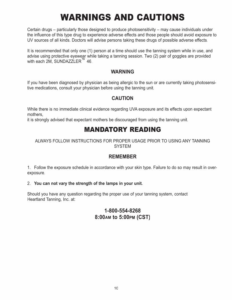
WARNINGS AND CAUTIONSCertain drugs – particularly those designed to produce photosensitivity – may cause individuals under the influence of this type drug to experience adverse effects and those people should avoid exposure to UV sources of all kinds. Doctors will advise persons taking these drugs of possible adverse effects.
It is recommended that only one (1) person at a time should use the tanning system while in use, and advise using protective eyewear while taking a tanning session. Two (2) pair of goggles are provided with each 2M, SUNDAZZLER™advise using protective eyewear while taking a tanning session. Two (2) pair of goggles are provided
™advise using protective eyewear while taking a tanning session. Two (2) pair of goggles are provided
46.
WARNING
If you have been diagnosed by physician as being allergic to the sun or are currently taking photosensi-tive medications, consult your physician before using the tanning unit.
CAUTION
While there is no immediate clinical evidence regarding UVA exposure and its effects upon expectant mothers, it is strongly advised that expectant mothers be discouraged from using the tanning unit.
MANDATORY READING
ALWAYS FOLLOW INSTRUCTIONS FOR PROPER USAGE PRIOR TO USING ANY TANNING SYSTEM
REMEMBER
1. Follow the exposure schedule in accordance with your skin type. Failure to do so may result in over-exposure.
2. You can not vary the strength of the lamps in your unit.
Should you have any question regarding the proper use of your tanning system, contact Heartland Tanning, Inc. at:
1-800-554-82688:00AM to 5:00PM (CST)
11
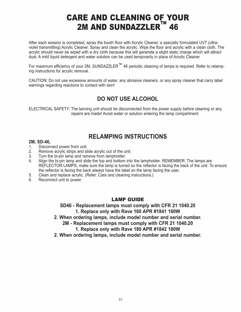
CARE AND CLEANING OF YOUR 2M AND SUNDAZZLER™ 46
After each session is completed, spray the booth floor with Acrylic Cleaner, a specially formulated UVT (ultra-violet transmitting) Acrylic Cleaner. Spray and clean the acrylic. Wipe the floor and acrylic with a clean cloth. The acrylic should never be wiped with a dry cloth because this will generate a slight static charge which will attract dust. A mild liquid detergent and water solution can be used temporarily in place of Acrylic Cleaner.
For maximum efficiency of your 2M, SUNDAZZLER™ 46 periodic cleaning of lamps is required. Refer to relamp-ing instructions for acrylic removal.
CAUTION: Do not use excessive amounts of water, any abrasive cleaners, or any spray cleaner that carry label warnings regarding reactions to contact with skin!
DO NOT USE ALCOHOL
ELECTRICAL SAFETY: The tanning unit should be disconnected from the power supply before cleaning or any repairs are made! Avoid water or solution entering the lamp compartment.
RELAMPING INSTRUCTIONS2M, SD-46, 1. Disconnect power from unit.2. Remove acrylic strips and slide acrylic out of the unit.3. Turn the bi-pin lamp and remove from lampholder.4. Align the bi-pin lamp and slide the top and bottom into the lampholder. REMEMBER: The lamps are
REFLECTOR LAMPS, make sure the lamp is turned so the reflector is facing the back of the unit. To ensure the reflector is facing the back always have the label on the lamp facing the user.
5. Clean and replace acrylic. (Refer: Care and cleaning instructions.)6. Reconnect unit to power.
LAMP GUIDESD46 - Replacement lamps must comply with CFR 21 1040.20
1. Replace only with Rave 160 APR #1841 160W2. When ordering lamps, include model number and serial number.
2M - Replacement lamps must comply with CFR 21 1040.201. Replace only with Rave 180 APR #1842 180W
2. When ordering lamps, include model number and serial number.
12
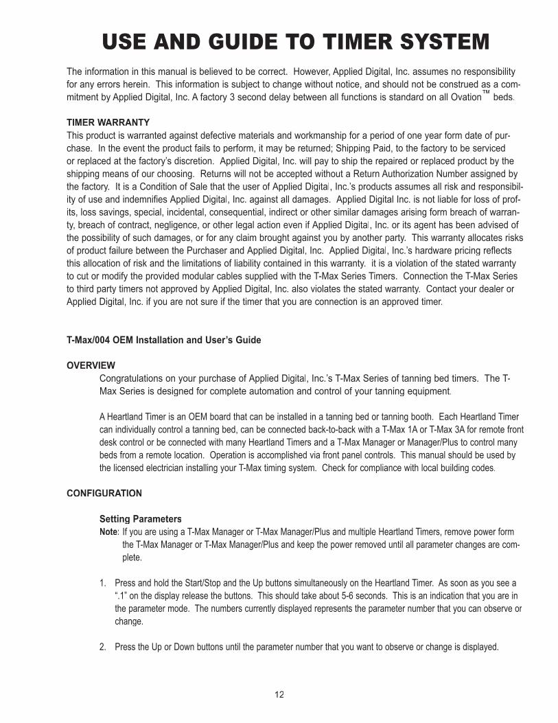
USE AND GUIDE TO TIMER SYSTEMThe information in this manual is believed to be correct. However, Applied Digital, Inc. assumes no responsibility for any errors herein. This information is subject to change without notice, and should not be construed as a com-mitment by Applied Digital, Inc. A factory 3 second delay between all functions is standard on all Ovation™ beds.
TIMER WARRANTYThis product is warranted against defective materials and workmanship for a period of one year form date of pur-chase. In the event the product fails to perform, it may be returned; Shipping Paid, to the factory to be serviced or replaced at the factory’s discretion. Applied Digital, Inc. will pay to ship the repaired or replaced product by the shipping means of our choosing. Returns will not be accepted without a Return Authorization Number assigned by the factory. It is a Condition of Sale that the user of Applied Digital, Inc.’s products assumes all risk and responsibil-ity of use and indemnifies Applied Digital, Inc. against all damages. Applied Digital Inc. is not liable for loss of prof-its, loss savings, special, incidental, consequential, indirect or other similar damages arising form breach of warran-ty, breach of contract, negligence, or other legal action even if Applied Digital, Inc. or its agent has been advised of the possibility of such damages, or for any claim brought against you by another party. This warranty allocates risks of product failure between the Purchaser and Applied Digital, Inc. Applied Digital, Inc.’s hardware pricing reflects this allocation of risk and the limitations of liability contained in this warranty. it is a violation of the stated warranty to cut or modify the provided modular cables supplied with the T-Max Series Timers. Connection the T-Max Series to third party timers not approved by Applied Digital, Inc. also violates the stated warranty. Contact your dealer or Applied Digital, Inc. if you are not sure if the timer that you are connection is an approved timer.
T-Max/004 OEM Installation and User’s Guide
OVERVIEW Congratulations on your purchase of Applied Digital, Inc.’s T-Max Series of tanning bed timers. The T-
Max Series is designed for complete automation and control of your tanning equipment.
A Heartland Timer is an OEM board that can be installed in a tanning bed or tanning booth. Each Heartland Timer A Heartland Timer is an OEM board that can be installed in a tanning bed or tanning booth. Each Heartland Timer can individually control a tanning bed, can be connected back-to-back with a T-Max 1A or T-Max 3A for remote front desk control or be connected with many Heartland Timers and a T-Max Manager or Manager/Plus to control many beds from a remote location. Operation is accomplished via front panel controls. This manual should be used by the licensed electrician installing your T-Max timing system. Check for compliance with local building codes.
CONFIGURATION
Setting ParametersNote: If you are using a T-Max Manager or T-Max Manager/Plus and multiple Heartland Timers, remove power form
the T-Max Manager or T-Max Manager/Plus and keep the power removed until all parameter changes are com-plete.
1. Press and hold the Start/Stop and the Up buttons simultaneously on the Heartland Timer. As soon as you see a “.1” on the display release the buttons. This should take about 5-6 seconds. This is an indication that you are in the parameter mode. The numbers currently displayed represents the parameter number that you can observe or change.
2. Press the Up or Down buttons until the parameter number that you want to observe or change is displayed.
13
3 Press the Start/Stop button. The current value for that parameter will be displayed and flashing.
The Heartland Timer will show a number with a period illuminated in the lower center of the display. The number shown is the current value for that parameter.
For Lamp, Session Counts, etc. the value displayed can be as high as 9999. To display this value, the Heartland Timer will flash tow numbers-three times, then two numbers-three times, pause, two numbers-three times, two numbers-three times, pause, etc. For example, if you are checking lamp hours (Parameter 6) and the display flashes the numbers 53 three times, then 14 three times, pauses then repeats, then the total lamp hours stored in that Heartland Timer is 5314.
4. Press the Up or Down buttons to change the parameter to the desired value. If you want to clear the value for that parameter, press the Up and Down buttons at the same
time until the display shows 0.0.
5. Press the Start/Stop button. The display will show the parameter number you just change and a solid period in the lower cen-
ter of the display. You may now change another parameter by pressing the Up and Down but-tons until the parameter that you want to change is displayed. Repeat Steps 2-4 for each param-eter you want to change.
6. To exit the Parameter mode and make the Heartland Timer available for the next session, press and hold the both Up and Down buttons until the display shows a 0 with no periods displayed.
14
0= When set to a 1, voltage must be applied be an outside sourceto the TPI input on the back of the Heartland Timer. Used is
the timer is being controlled by either a FST® orDatabase® Series Timer. See Section for JPI settings
0 = After a session ends and the clean room is cleared, theHeartland Timer will show a 0. 1 = After session ends and theclean room is cleared,m the Heartland Timer will show thelast session time entered.2 = After the session ends and the
clean room is cleared,the max.time will show on theHeartland Timer.
0 = Press and hold the Set button for 3-4 seconds to clearthe clean room. 1 = Press and release the Set button to
instantly clear the clean room.
0 = Disabled, 1 = Enabled. When session starts, the relay on theT-Max® 1A will close for 1-2 seconds then open.
Counts number of sessions ran through the TMax® 3A. Thisvalue cannot be changed at all. Used as point of reference.
0 = Disabled, 1 = Enabled. Heartland Timer will beep for 10seconds every 5 minutes
0 = Disabled, 1-10 = Enabled. Time delay in minutes allowingbed to cool. The fans will remain running while the Heartland
Timer is in cool down mode.
0 = Stand Alone Enabled. 1 = Disabled0 = Clean Room Disabled. 1 = Enabled
0Bed Hours
Manual SessionCounts
Counts the # of sessions the Heartland Timer Session has runwhile in Stand Alone Mode
65
7 6553565535
1
0
0
0
3
06553510
Lamp HoursSession
Delay Time
How may hours a bed is onBulb hours for each bed
Total Session counts for Heartland Timer CountsDelay in minutes stored in the Heartland Timer
Beep Mode Used for High Power beds. 0=Alarm Only, 1=Alarm and Flip
19*
16
18
15
17
14
13
1098
3
0
12
1
128Address1
Manual Lockout*
65535
NOTESDEFAULTMAX#DESCRIPTION
Set this number to the room number you want the timer to be
PARAM.#SALON LEVEL
Clean Room
301
0
0
0
0
0
1
10
1
65535
1
1
2
Cool Down Mode
5 MIN. Beep
Fixed Session
Pulse Mode
Clean Clear
Redisplay
Third PartyInterface
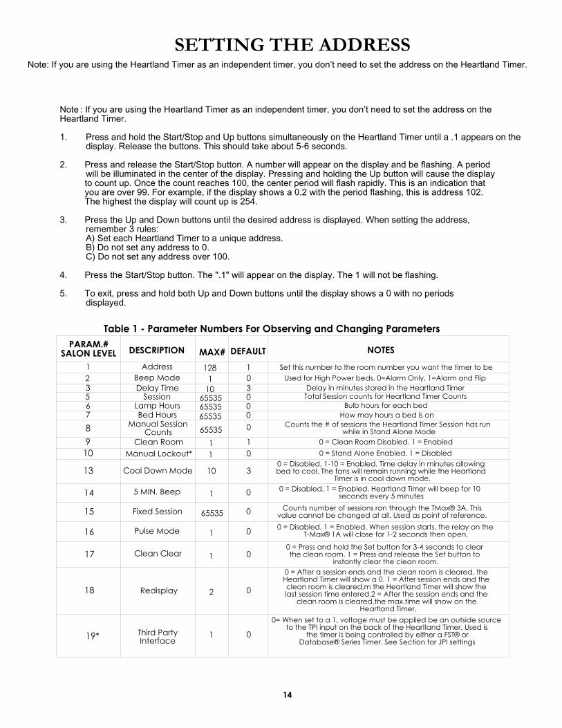
Table 1 - Parameter Numbers For Observing and Changing Parameters
Note : If you are using the Heartland Timer as an independent timer, you don’t need to set the address on theHeartland Timer.
Press and hold the Start/Stop and Up buttons simultaneously on the Heartland Timer until a .1 appears on the1.display. Release the buttons. This should take about 5-6 seconds.
2. Press and release the Start/Stop button. A number will appear on the display and be flashing. A periodwill be illuminated in the center of the display. Pressing and holding the Up button will cause the display
to count up. Once the count reaches 100, the center period will flash rapidly. This is an indication that you are over 99. For example, if the display shows a 0.2 with the period flashing, this is address 102. The highest the display will count up is 254.
3. Press the Up and Down buttons until the desired address is displayed. When setting the address,remember 3 rules:A) Set each Heartland Timer to a unique address. B) Do not set any address to 0.C) Do not set any address over 100.
4. Press the Start/Stop button. The ".1" will appear on the display. The 1 will not be flashing.
5. To exit, press and hold both Up and Down buttons until the display shows a 0 with no periods displayed.
1
SETTING THE ADDRESSNote: If you are using the Heartland Timer as an independent timer, you don’t need to set the address on the Heartland Timer.

15
Setting Delay Time
If the Heartland Timer is being controlled by a T-Max 1A, T-Max 3A, T-Max Manager or T-Max Manager/Plus, the delay does not need to be set on the Heartland Timer. The delay is controlled by the controlling device.
1. Press and hold the Start/Stop and Up buttons simultaneously the Heartland Timer until a “.1” appears on the display. Release the buttons. This should take about 5-6 seconds.
2. Press the Up or Down button until a “.3” is displayed.
3. Press and release the Start/Stop button. A number will appear on the display and be flashing. A period will be illuminated in the center of the display. This is the current delay time.
4. Press the Up or Down button until the desired delay time is displayed. The highest delay time that can be set on the Heartland Timer is 10 minutes. If you want no delay time, set the display to 0. If you set the delay time to 0, the session time will start immediately after the Start/Stop button is pressed.
5. Press the Start/Stop button. The “.3” will appear on the display. The 3 will not be flashing.
6. To exit, press and hold both the Up and Down buttons until the display shows a “0” with no periods displayed.
IN-ROOM SINGLE BED CONTROL
Starting A Session1. Press the Up or Down button on the Heartland Timer until the desired session time is displayed. If
the display shows a 0, and you want to count down from the maximum time, press the down button.
2. Press and release the Start/Stop button to start the session. If a delay other that 0 is entered, the delay will count down. A period on the lower right corner of the display will flash rapidly. When the session starts, the period will flash at a once per second rate. If the delay is set to 0, the session will start immediately.
Pausing A Session To pause the session press the Start/Stop button. The flashing period on the lower right corner of the
display will stop flashing and stay illuminated. To restart, press the Start/Stop button on the Heartland Timer. The period on the lower right corner of the display will resume flashing.NOTE: The session time will continue to count down. The display will continue to update and reflect the
remaining session time.
Canceling A Session To cancel a session. press the Start/Stop button to pause the session then press the Up button. The display will show a solitary 0.
REMOTE SINGLE BED CONTROL
Remote Single Bed Control is the ability to control a single tanning bed from a remote location. T-Max 3A at the remote location is required for this configuration.

16
Wiring Wire the Heartland Timer to the tanning bed. Apply power to the T-Max 3A as described in their respective
User’s Guides.
Run the provided modular cable from the tanning room to the remote T-Max 3A or T-Max 1A. Connect the modular cable to one of the RJ-22 ports on the Heartland Timer and T-Max 1A or T-Max 3A (see RJ-22 ports for T-Max Series timers on page 16, figure B).
Configuration Set the address on the Heartland Timer in the tanning room to 1. Set the address on the T-Max 3A to 0.0. For
setting the delay refer to the T-Max 3A user’s guide.
Note: When setting the address on the Heartland Timer in the tanning room, the power to the front desk T-Max 1A or 3A must be off.
Session Control Starting a session 1. Press the Up and Down button on the T-Max 3A or the Set button on the T-Max 1A at the front desk until the
session time is displayed. Time cannot be set from the Heartland Timer in the room.
2. Press the Start/Stop button on the front desk T-Max 1A or T-Max 3A to start the session.
If a delay other than 0 is set, the delay will count down. A period on the lower right corner of the display will flash rapidly. When the session starts, the period will flash at once per second rate. If a 0 delay is entered, the session will start immediately.
Pause during the Session To pause the session press the Start/Stop button on the Heartland Timer in the tanning room. The flashing peri-
od on the lower right corner of the display will stop flashing and stay illuminated. To restart the session, press the Start/Stop button on the Heartland Timer in the tanning room. The period will continue flashing.
Note: The session time will continue to count down. The display will continue to update and reflect the remain-ing session time.
Canceling a session To cancel a session, press both the Start/Stop band Up button on the T-Max 3A at the front desk simultaneous-
ly. If you are using a T-Max 1A, press the Start/Stop and the Set buttons simultaneously. The session cannot be canceled from the Heartland Timer.
USING THE HEARTLAND TIMER WITH A T-MAX MANAGER OR T-MAX MANAGER/PLUS/PRO If you are using Heartland Timers with a T-Max Manager or T-Max Manager/Plus, follow these instructions for proper operation:
If you need to set the address on the Heartland Timer manually, be sure to set each Heartland Timer to a different address. No Heartland Timer should be set to address 00.
Connect each Heartland Timer together using a modular cable that conforms to the pinouts shown on Figure B. Connect T-Max Manager or T-Max Manager/Plus to the closest Heartland Timer in the line (refer to Figure C).Note: Delay is controlled by the T-Max Manager, the T-Max Manager/Plus or the software you are using if you are using a computer. It is not necessary to set the delay on the Heartland Timer. Refer to the T-Max Manager or T-Max Manager/Plus User’s Guide for operation.
17
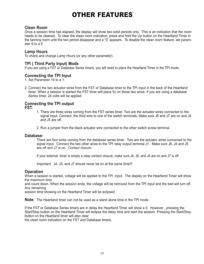
OTHER FEATURES
Clean Room Once a session time has elapsed, the display will show two solid periods only. This is an indication that the room
needs to be cleaned. To clear the clean room indication, press and hold the Up button on the Heartland Timer in the tanning room until the two period disappear and a “0” appears. To disable the clean room feature, set param-eter 9 to a 0.
Lamp Hours To check and change Lamp Hours (or any other parameter).
TPI ( Third Party Input) ModeIf you are using a FST or Database Series timers, you will need to place the Heartland Timer in the TPI mode.
Connecting the TPI Input 1. Set Parameter 19 to a 1.
2. Connect the two actuator wires from the FST or Database timer to the TPI input in the back of the Heartland timer. When a session is started the FST timer will place 5v on these two wires. If you are using a database Series timer, 24 volts will be applied.
Connecting the TPI outputFST:Connecting the TPI outputFST:Connecting the TPI output
1. There are three wires coming from the FST series timer. Two are the actuator wires connected to the signal input. Connect the third wire to one of the switch terminals. Make sure J6 and J7 are on and J4 and J5 are off.
2. Run a jumper from the black actuator wire connected to the other switch screw terminal.
Database: There are four wires coming from the database series timer. Two are the actuator wires connected to the
signal input. Connect the two other wires to the TPI relay output terminal J1. Make sure J6, J4 and J5 are off and J7 is on. Contact closure
If your external timer is simply a relay contact closure, make sure J4, J6, and J5 are on and J7 is off.
Important: J4, J5, and J7 should never be on at the same time!!!
Operation When a session is started, voltage will be applied to the TPI input. The display on the Heartland Timer will show
the maximum time and count down. When the session ends, the voltage will be removed from the TPI input and the bed will turn off. Any remaining session time showing on the Heartland Timer will be eclipsed.
Note: The Heartland timer can not be used as a stand alone time in the TPI mode.
If the FST or Database Series timers are in delay the Heartland Timer will show a 0. However , pressing the Start/Stop button on the Heartland Timer will eclipse the delay time and start the session. Pressing the Start/Stop button on the Heartland timer will also clear the clean room indication on the FST and Database timers.
18
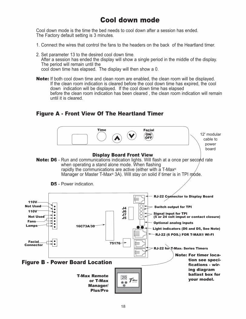
Cool down mode Cool down mode is the time the bed needs to cool down after a session has ended. The Factory default setting is 3 minutes.
1. Connect the wires that control the fans to the headers on the back of the Heartland timer.
2. Set parameter 13 to the desired cool down time.After a session has ended the display will show a single period in the middle of the display. The period will remain until the cool down time has elapsed. The display will then show a 0.
Note: If both cool down time and clean room are enabled, the clean room will be displayed. If the clean room indication is cleared before the cool down time has expired, the cool down indication will be displayed. If the cool down time has elapsed before the clean room indication has been cleared , the clean room indication will remain until it is cleared.
Figure A - Front View Of The Heartland Timer
Display Board Front View Note: D6 - Run and communications indication lights. Will flash at a once per second rate
when operating a stand alone mode. When flashing rapidly the communications are active (either with a T-Max®
Manager or Master T-Max® 3A). Will stay on solid if timer is in TPI mode.® 3A). Will stay on solid if timer is in TPI mode.®
D5 - Power indication.
Figure B - Power Board Location
- Run and communications indication lights. Will flash at a once per second rate
3A). Will stay on solid if timer is in TPI mode.
Note: For timer loca-tion see speci-fications - wir-ing diagram ballast box for your model.
12' modular cable topowerboard
T-Max Remoteor T-Max Manager/Plus/Pro
19
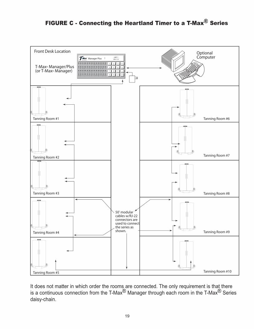
FIGURE C - Connecting the Heartland Timer to a T-Max®® Series
It does not matter in which order the rooms are connected. The only requirement is that there is a continuous connection from the T-Max®It does not matter in which order the rooms are connected. The only requirement is that there
®It does not matter in which order the rooms are connected. The only requirement is that there
Manager through each room in the T-Max® Manager through each room in the T-Max® ®It does not matter in which order the rooms are connected. The only requirement is that there
®It does not matter in which order the rooms are connected. The only requirement is that there
Series ® Series ®
daisy-chain.

20
ASSEMBLY INSTRUCTIONS
UNIT1/2" BOLTS1/2" BOLTS
LOWER LOUVEREDPANEL LOWER LOUVERED
PANEL
ALIGNMENT HOLE
ALIGNMENT PIN
BASE
STEP 2
STEP 1
STEP 2
STEP 1
STEP 2
STEP 1
21
ASSEMBLY INSTRUCTIONS
3/8" X 1" HEX BOLTS
HINGEBRACKET
TOP OF UNIT
WASHERFIG. 3
FIG. 2
HINGEBRACKET ONTOP OF UNIT
PIN ONDOOR
BUSHING ONSIDE OF UNITFLOOR
PIN ONDOOR
ADJUSTMENTPLATE
FIG. 1
STEP 4
STEP 4
STEP 3
22
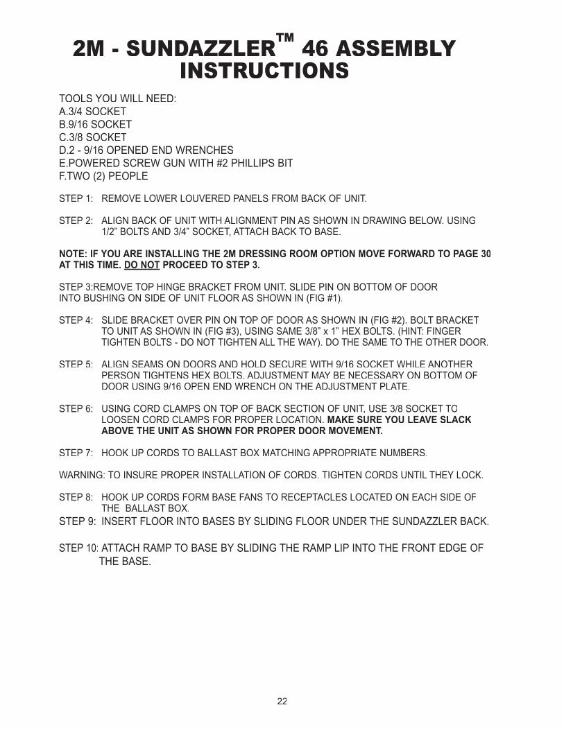
2M - SUNDAZZLER™ 46 ASSEMBLY INSTRUCTIONS
TOOLS YOU WILL NEED: A.3/4 SOCKET B.9/16 SOCKET C.3/8 SOCKET D.2 - 9/16 OPENED END WRENCHES E.POWERED SCREW GUN WITH #2 PHILLIPS BIT F.TWO (2) PEOPLE
STEP 1: REMOVE LOWER LOUVERED PANELS FROM BACK OF UNIT.
STEP 2: ALIGN BACK OF UNIT WITH ALIGNMENT PIN AS SHOWN IN DRAWING BELOW. USING 1/2” BOLTS AND 3/4” SOCKET, ATTACH BACK TO BASE.
NOTE: IF YOU ARE INSTALLING THE 2M DRESSING ROOM OPTION MOVE FORWARD TO PAGE 30 AT THIS TIME. DO NOT PROCEED TO STEP 3.
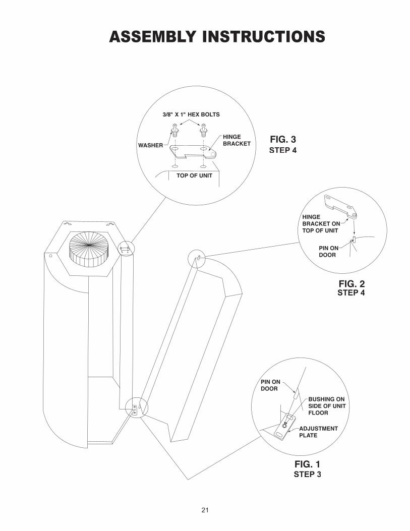
STEP 3: REMOVE TOP HINGE BRACKET FROM UNIT. SLIDE PIN ON BOTTOM OF DOOR INTO BUSHING ON SIDE OF UNIT FLOOR AS SHOWN IN (FIG #1).
STEP 4: SLIDE BRACKET OVER PIN ON TOP OF DOOR AS SHOWN IN (FIG #2). BOLT BRACKET TO UNIT AS SHOWN IN (FIG #3), USING SAME 3/8” x 1” HEX BOLTS. (HINT: FINGER TIGHTEN BOLTS - DO NOT TIGHTEN ALL THE WAY). DO THE SAME TO THE OTHER DOOR.
STEP 5: ALIGN SEAMS ON DOORS AND HOLD SECURE WITH 9/16 SOCKET WHILE ANOTHER PERSON TIGHTENS HEX BOLTS. ADJUSTMENT MAY BE NECESSARY ON BOTTOM OF DOOR USING 9/16 OPEN END WRENCH ON THE ADJUSTMENT PLATE.
STEP 6: USING CORD CLAMPS ON TOP OF BACK SECTION OF UNIT, USE 3/8 SOCKET TO LOOSEN CORD CLAMPS FOR PROPER LOCATION. MAKE SURE YOU LEAVE SLACK ABOVE THE UNIT AS SHOWN FOR PROPER DOOR MOVEMENT.
STEP 7: HOOK UP CORDS TO BALLAST BOX MATCHING APPROPRIATE NUMBERS.
WARNING: TO INSURE PROPER INSTALLATION OF CORDS. TIGHTEN CORDS UNTIL THEY LOCK.
STEP 8: HOOK UP CORDS FORM BASE FANS TO RECEPTACLES LOCATED ON EACH SIDE OF THE BALLAST BOX. STEP 9: INSERT FLOOR INTO BASES BY SLIDING FLOOR UNDER THE SUNDAZZLER BACK.
STEP 10: ATTACH RAMP TO BASE BY SLIDING THE RAMP LIP INTO THE FRONT EDGE OF THE BASE.
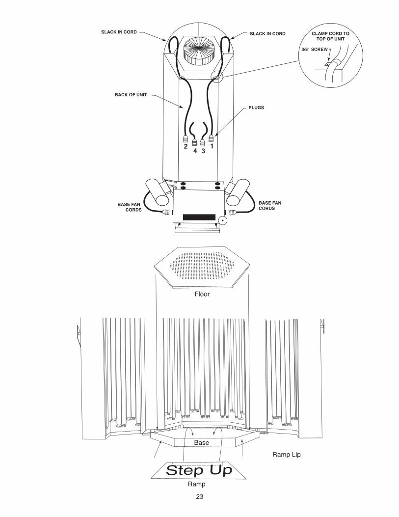
23
Floor
Ramp LipBase
Ramp
SLACK IN CORD CLAMP CORD TOTOP OF UNIT
BACK OF UNIT
BASE FAN CORDS
BASE FAN CORDS
SLACK IN CORD
3/8" SCREW
PLUGS
2 4 31
24
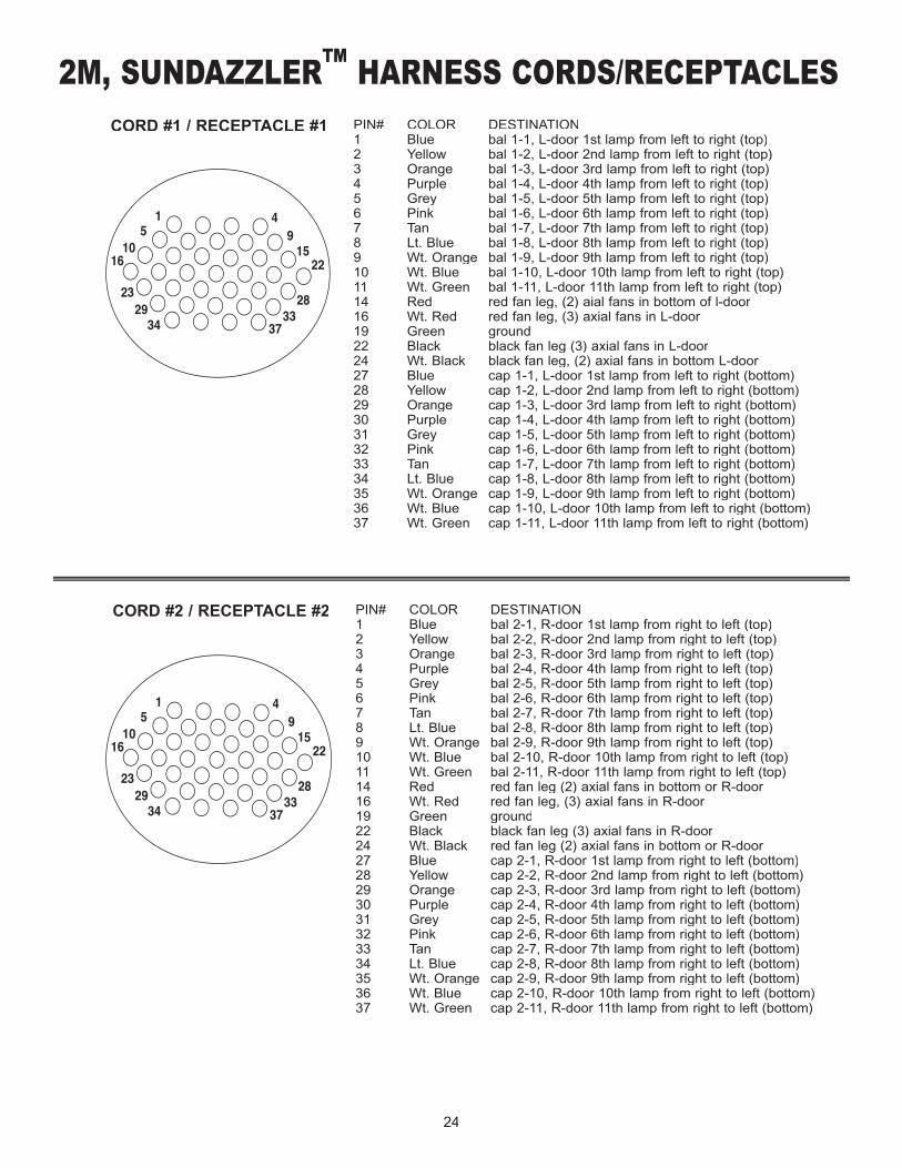
PIN# COLOR DESTINATION1 Blue bal 1-1, L-door 1st lamp from left to right (top)2 Yellow bal 1-2, L-door 2nd lamp from left to right (top)3 Orange bal 1-3, L-door 3rd lamp from left to right (top)4 Purple bal 1-4, L-door 4th lamp from left to right (top)5 Grey bal 1-5, L-door 5th lamp from left to right (top)6 Pink bal 1-6, L-door 6th lamp from left to right (top)7 Tan bal 1-7, L-door 7th lamp from left to right (top)8 Lt. Blue bal 1-8, L-door 8th lamp from left to right (top)9 Wt. Orange bal 1-9, L-door 9th lamp from left to right (top)10 Wt. Blue bal 1-10, L-door 10th lamp from left to right (top)11 Wt. Green bal 1-11, L-door 11th lamp from left to right (top)14 Red red fan leg, (2) aial fans in bottom of l-door16 Wt. Red red fan leg, (3) axial fans in L-door19 Green ground22 Black black fan leg (3) axial fans in L-door24 Wt. Black black fan leg, (2) axial fans in bottom L-door27 Blue cap 1-1, L-door 1st lamp from left to right (bottom)28 Yellow cap 1-2, L-door 2nd lamp from left to right (bottom)29 Orange cap 1-3, L-door 3rd lamp from left to right (bottom)30 Purple cap 1-4, L-door 4th lamp from left to right (bottom)31 Grey cap 1-5, L-door 5th lamp from left to right (bottom)32 Pink cap 1-6, L-door 6th lamp from left to right (bottom)33 Tan cap 1-7, L-door 7th lamp from left to right (bottom)34 Lt. Blue cap 1-8, L-door 8th lamp from left to right (bottom)35 Wt. Orange cap 1-9, L-door 9th lamp from left to right (bottom)36 Wt. Blue cap 1-10, L-door 10th lamp from left to right (bottom)37 Wt. Green cap 1-11, L-door 11th lamp from left to right (bottom)
CORD #1 / RECEPTACLE #1
15
1016
232934 37
3328
2215
94
PIN# COLOR DESTINATION1 Blue bal 2-1, R-door 1st lamp from right to left (top)2 Yellow bal 2-2, R-door 2nd lamp from right to left (top)3 Orange bal 2-3, R-door 3rd lamp from right to left (top)4 Purple bal 2-4, R-door 4th lamp from right to left (top)5 Grey bal 2-5, R-door 5th lamp from right to left (top)6 Pink bal 2-6, R-door 6th lamp from right to left (top)7 Tan bal 2-7, R-door 7th lamp from right to left (top)8 Lt. Blue bal 2-8, R-door 8th lamp from right to left (top)9 Wt. Orange bal 2-9, R-door 9th lamp from right to left (top)10 Wt. Blue bal 2-10, R-door 10th lamp from right to left (top)11 Wt. Green bal 2-11, R-door 11th lamp from right to left (top)14 Red red fan leg (2) axial fans in bottom or R-door16 Wt. Red red fan leg, (3) axial fans in R-door19 Green ground22 Black black fan leg (3) axial fans in R-door24 Wt. Black red fan leg (2) axial fans in bottom or R-door27 Blue cap 2-1, R-door 1st lamp from right to left (bottom)28 Yellow cap 2-2, R-door 2nd lamp from right to left (bottom)29 Orange cap 2-3, R-door 3rd lamp from right to left (bottom)30 Purple cap 2-4, R-door 4th lamp from right to left (bottom)31 Grey cap 2-5, R-door 5th lamp from right to left (bottom)32 Pink cap 2-6, R-door 6th lamp from right to left (bottom)33 Tan cap 2-7, R-door 7th lamp from right to left (bottom)34 Lt. Blue cap 2-8, R-door 8th lamp from right to left (bottom)35 Wt. Orange cap 2-9, R-door 9th lamp from right to left (bottom)36 Wt. Blue cap 2-10, R-door 10th lamp from right to left (bottom)37 Wt. Green cap 2-11, R-door 11th lamp from right to left (bottom)
CORD #2 / RECEPTACLE #2
15
1016
232934 37
3328
2215
94
2M, SUNDAZZLER™™™ HARNESS CORDS/RECEPTACLES
25
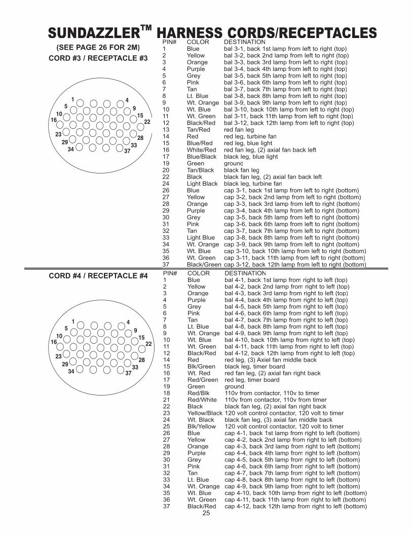
PIN# COLOR DESTINATION1 Blue bal 3-1, back 1st lamp from left to right (top)2 Yellow bal 3-2, back 2nd lamp from left to right (top)3 Orange bal 3-3, back 3rd lamp from left to right (top)4 Purple bal 3-4, back 4th lamp from left to right (top)5 Grey bal 3-5, back 5th lamp from left to right (top)6 Pink bal 3-6, back 6th lamp from left to right (top)7 Tan bal 3-7, back 7th lamp from left to right (top)8 Lt. Blue bal 3-8, back 8th lamp from left to right (top)9 Wt. Orange bal 3-9, back 9th lamp from left to right (top)10 Wt. Blue bal 3-10, back 10th lamp from left to right (top)11 Wt. Green bal 3-11, back 11th lamp from left to right (top)12 Black/Red bal 3-12, back 12th lamp from left to right (top)13 Tan/Red red fan leg 14 Red red leg, turbine fan15 Blue/Red red leg, blue light16 White/Red red fan leg, (2) axial fan back left17 Blue/Black black leg, blue light19 Green ground20 Tan/Black black fan leg22 Black black fan leg, (2) axial fan back left24 Light Black black leg, turbine fan26 Blue cap 3-1, back 1st lamp from left to right (bottom)27 Yellow cap 3-2, back 2nd lamp from left to right (bottom)28 Orange cap 3-3, back 3rd lamp from left to right (bottom)29 Purple cap 3-4, back 4th lamp from left to right (bottom)30 Grey cap 3-5, back 5th lamp from left to right (bottom)31 Pink cap 3-6, back 6th lamp from left to right (bottom)32 Tan cap 3-7, back 7th lamp from left to right (bottom)33 Light Blue cap 3-8, back 8th lamp from left to right (bottom)34 Wt. Orange cap 3-9, back 9th lamp from left to right (bottom)35 Wt. Blue cap 3-10, back 10th lamp from left to right (bottom)36 Wt. Green cap 3-11, back 11th lamp from left to right (bottom)37 Black/Green cap 3-12, back 12th lamp from left to right (bottom)
PIN# COLOR DESTINATION1 Blue bal 4-1, back 1st lamp from right to left (top)2 Yellow bal 4-2, back 2nd lamp from right to left (top)3 Orange bal 4-3, back 3rd lamp from right to left (top)4 Purple bal 4-4, back 4th lamp from right to left (top)5 Grey bal 4-5, back 5th lamp from right to left (top)6 Pink bal 4-6, back 6th lamp from right to left (top)7 Tan bal 4-7, back 7th lamp from right to left (top)8 Lt. Blue bal 4-8, back 8th lamp from right to left (top)9 Wt. Orange bal 4-9, back 9th lamp from right to left (top)10 Wt. Blue bal 4-10, back 10th lamp from right to left (top)11 Wt. Green bal 4-11, back 11th lamp from right to left (top)12 Black/Red bal 4-12, back 12th lamp from right to left (top)14 Red red leg, (3) Axiel fan middle back15 Blk/Green black leg, timer board16 Wt. Red red fan leg, (2) axial fan right back17 Red/Green red leg, timer board19 Green ground18 Red/Blk 110v from contactor, 110v to timer21 Red/White 110v from contactor, 110v from timer22 Black black fan leg, (2) axial fan right back23 Yellow/Black 120 volt control contactor, 120 volt to timer24 Wt. Black black fan leg, (3) axial fan middle back25 Blk/Yellow 120 volt control contactor, 120 volt to timer26 Blue cap 4-1, back 1st lamp from right to left (bottom)27 Yellow cap 4-2, back 2nd lamp from right to left (bottom)28 Orange cap 4-3, back 3rd lamp from right to left (bottom)29 Purple cap 4-4, back 4th lamp from right to left (bottom)30 Grey cap 4-5, back 5th lamp from right to left (bottom)31 Pink cap 4-6, back 6th lamp from right to left (bottom)32 Tan cap 4-7, back 7th lamp from right to left (bottom)33 Lt. Blue cap 4-8, back 8th lamp from right to left (bottom)34 Wt. Orange cap 4-9, back 9th lamp from right to left (bottom)35 Wt. Blue cap 4-10, back 10th lamp from right to left (bottom)36 Wt. Green cap 4-11, back 11th lamp from right to left (bottom)37 Black/Red cap 4-12, back 12th lamp from right to left (bottom)
37 Black/Green cap 3-12, back 12th lamp from left to right (bottom)
(SEE PAGE 26 FOR 2M)
CORD #3 / RECEPTACLE #3
CORD #4 / RECEPTACLE #4
15
1016
232934 37
3328
2215
94
15
1016
232934 37
3328
2215
94
SUNDAZZLER™ HARNESS CORDS/RECEPTACLES
26
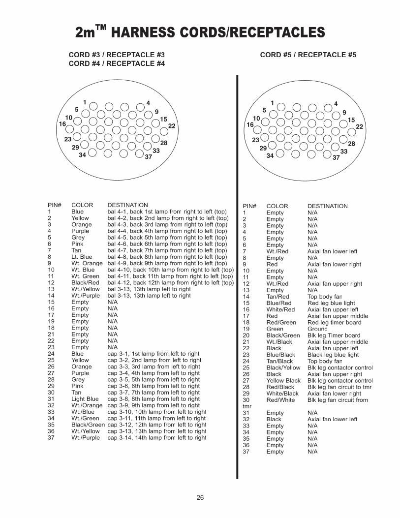
PIN# COLOR DESTINATION1 Blue bal 4-1, back 1st lamp from right to left (top)2 Yellow bal 4-2, back 2nd lamp from right to left (top)3 Orange bal 4-3, back 3rd lamp from right to left (top)4 Purple bal 4-4, back 4th lamp from right to left (top)5 Grey bal 4-5, back 5th lamp from right to left (top)6 Pink bal 4-6, back 6th lamp from right to left (top)7 Tan bal 4-7, back 7th lamp from right to left (top)8 Lt. Blue bal 4-8, back 8th lamp from right to left (top)9 Wt. Orange bal 4-9, back 9th lamp from right to left (top)10 Wt. Blue bal 4-10, back 10th lamp from right to left (top)11 Wt. Green bal 4-11, back 11th lamp from right to left (top)12 Black/Red bal 4-12, back 12th lamp from right to left (top)13 Wt./Yellow bal 3-13, 13th lamp left to right14 Wt./Purple bal 3-13, 13th lamp left to right15 Empty N/A16 Empty N/A17 Empty N/A19 Empty N/A18 Empty N/A21 Empty N/A22 Empty N/A23 Empty N/A24 Blue cap 3-1, 1st lamp from left to right25 Yellow cap 3-2, 2nd lamp from left to right26 Orange cap 3-3, 3rd lamp from left to right27 Purple cap 3-4, 4th lamp from left to right28 Grey cap 3-5, 5th lamp from left to right29 Pink cap 3-6, 6th lamp from left to right30 Tan cap 3-7, 7th lamp from left to right31 Light Blue cap 3-8, 8th lamp from left to right32 Wt./Orange cap 3-9, 9th lamp from left to right33 Wt./Blue cap 3-10, 10th lamp from left to right34 Wt./Green cap 3-11, 11th lamp from left to right35 Black/Green cap 3-12, 12th lamp from left to right36 Wt./Yellow cap 3-13, 13th lamp from left to right37 Wt./Purple cap 3-14, 14th lamp from left to right
CORD #3 / RECEPTACLE #3CORD #4 / RECEPTACLE #4
15
1016
232934 37
3328
2215
94
2m™ HARNESS CORDS/RECEPTACLES
PIN# COLOR DESTINATION1 Empty N/A2 Empty N/A3 Empty N/A4 Empty N/A5 Empty N/A6 Empty N/A7 Wt./Red Axial fan lower left8 Empty N/A9 Red Axial fan lower right10 Empty N/A11 Empty N/A12 Wt./Red Axial fan upper right13 Empty N/A14 Tan/Red Top body fan15 Blue/Red Red leg blue light16 White/Red Axial fan upper left17 Red Axial fan upper middle18 Red/Green Red leg timer board19 Green Ground20 Black/Green Blk leg Timer board21 Wt./Black Axial fan upper middle22 Black Axial fan upper left23 Blue/Black Black leg blue light24 Tan/Black Top body fan25 Black/Yellow Blk leg contactor control26 Black Axial fan upper right27 Yellow Black Blk leg contactor control28 Red/Black Blk leg fan circuit to tmr29 White/Black Axial fan lower right30 Red/White Blk leg fan circuit from tmr31 Empty N/A32 Black Axial fan lower left33 Empty N/A34 Empty N/A35 Empty N/A36 Empty N/A37 Empty N/A
CORD #5 / RECEPTACLE #5
15
1016
232934 37
3328
2215
94
27
Rec
epta
cle#
2
-Yel
low
18g
a fr
om p
in (#
28)
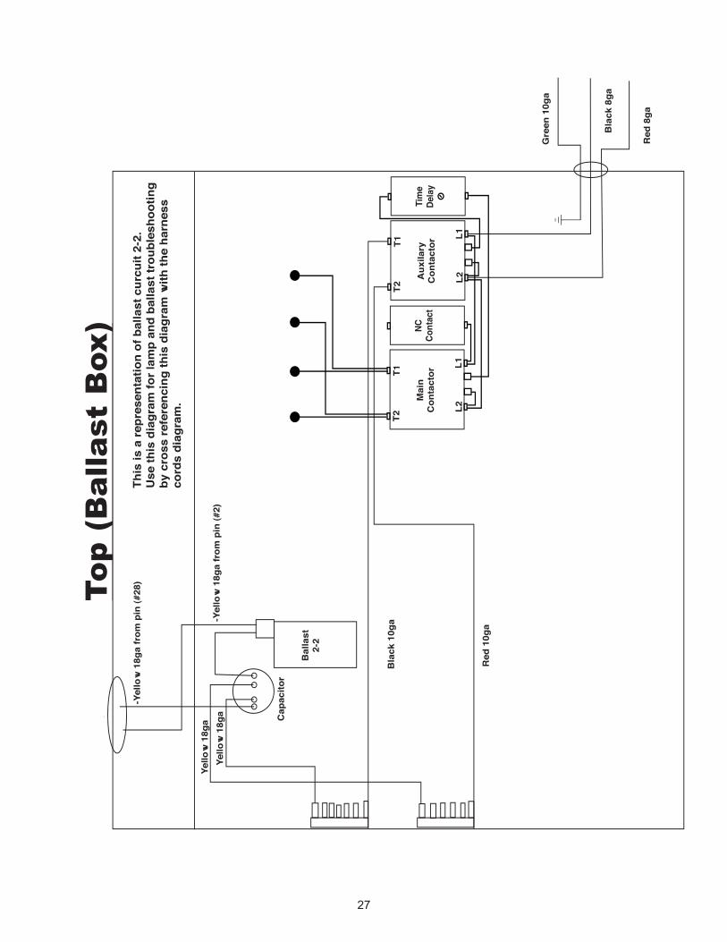
This
is a
repr
esen
tatio
n of
bal
last
cur
cuit
2-2.
Use
this
dia
gram
for l
amp
and
balla
st tr
oubl
esho
otin
gby
cro
ss re
fere
ncin
g th
is d
iagr
am w
ith th
e ha
rnes
sco
rds
diag
ram
.
-Yel
low
18g
a fr
om p
in (#
2)Ye
llow
18g
aYe
llow
18g
a
Bal
last
2-2
Cap
acito
r
Bla
ck 1
0ga
Red
10g
a
Red
8ga
Bla
ck 8
ga
Gre
en 1
0ga
Aux
ilary
Con
tact
or
L1L2
T1T2
Tim
eDe
lay
Mai
nC
onta
ctor
L1L2
T1T2
NCCo
ntac
t
To
p (
Ba
lla
st
Box
)To
p (
Ba
lla
st
Box
)
28
fan
fan
fan
fan
2-8
2-7
2-6
1-3
1-2
1-1
2-11
2-10
2-9
1-4
1-5
1-6
1-7
1-8
1-9
1-10
1-11
2-5
2-4
2-3
2-2
2-1
Auxilary
Con
tactor
L1L2
T1T2
Time
Delay
Main
Con
tactor
L1L2
T1T2
NC
Con
tact
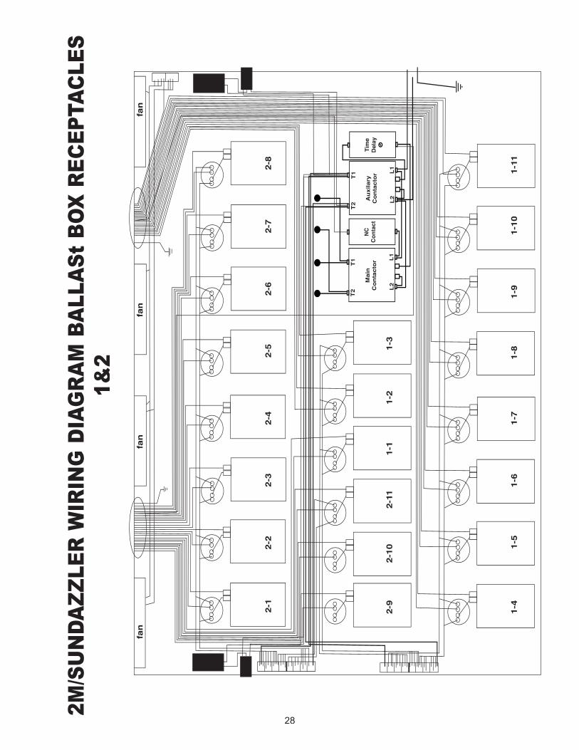
2M
/SU
ND
AZ
ZL
ER
WIR
ING
DIA
GR
AM
BA
LL
AS
t B
OX
RE
CE
PTA
CL
ES
1
&2
29
fan
fan
fan
fan
3-1
3-2
3-3
3-4
3-5
3-6
3-7
3-8
3-9
3-10
3-11
3-12
4-1
4-2
4-3
4-4
4-5
4-6
4-7
4-8
4-9
4-10
4-11
4-12
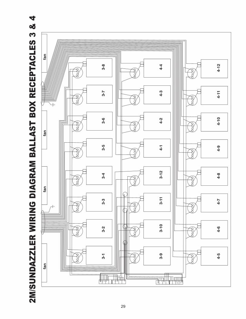
2M
/SU
ND
AZ
ZL
ER
WIR
ING
DIA
GR
AM
BA
LL
AS
T B
OX
RE
CE
PTA
CL
ES
3 &
4

30
SUNDAZZLER™/2mCHANGING ROOM
ASSEMBLY
31
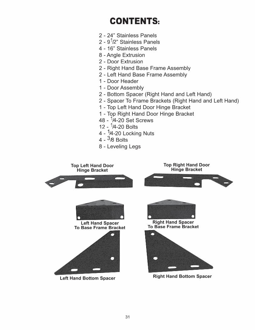
CONTENTS:
2 - 24” Stainless Panels2 - 91/2/2/ ” Stainless Panels4 - 16” Stainless Panels8 - Angle Extrusion2 - Door Extrusion2 - Right Hand Base Frame Assembly2 - Left Hand Base Frame Assembly1 - Door Header1 - Door Assembly2 - Bottom Spacer (Right Hand and Left Hand)2 - Spacer To Frame Brackets (Right Hand and Left Hand)1 - Top Left Hand Door Hinge Bracket1 - Top Right Hand Door Hinge Bracket48 - 11 - Top Right Hand Door Hinge Bracket
11 - Top Right Hand Door Hinge Bracket
/4/4/ -20 Set Screws12 - 1/4/4/ -20 Bolts4 - 1/4/4/ -20 Locking Nuts4 - 3/8/8/ Bolts8 - Leveling Legs
Top Left Hand DoorHinge Bracket
Top Right Hand DoorHinge Bracket
Left Hand Spacer To Base Frame Bracket
Right Hand Spacer To Base Frame Bracket
Right Hand Bottom SpacerLeft Hand Bottom Spacer
32
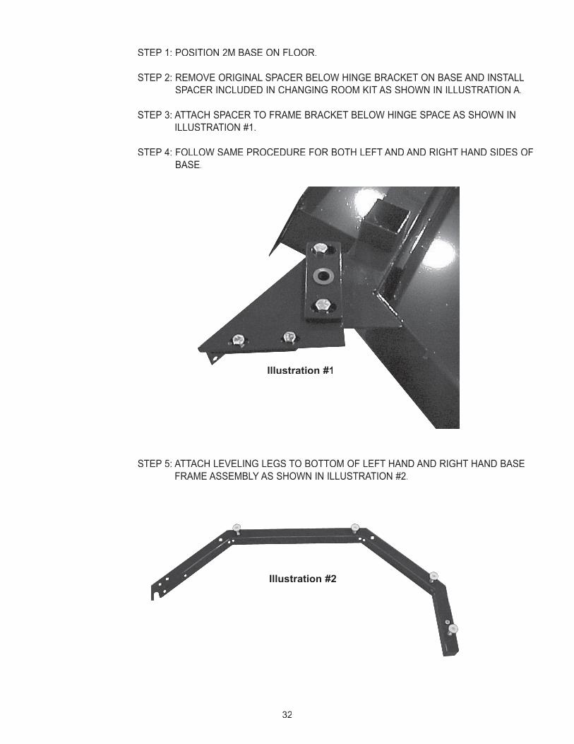
STEP 1: POSITION 2M BASE ON FLOOR.
STEP 2: REMOVE ORIGINAL SPACER BELOW HINGE BRACKET ON BASE AND INSTALL SPACER INCLUDED IN CHANGING ROOM KIT AS SHOWN IN ILLUSTRATION A.
STEP 3: ATTACH SPACER TO FRAME BRACKET BELOW HINGE SPACE AS SHOWN IN ILLUSTRATION #1.
STEP 4: FOLLOW SAME PROCEDURE FOR BOTH LEFT AND AND RIGHT HAND SIDES OF BASE.
STEP 5: ATTACH LEVELING LEGS TO BOTTOM OF LEFT HAND AND RIGHT HAND BASE FRAME ASSEMBLY AS SHOWN IN ILLUSTRATION #2.
Illustration #1
Illustration #2

33
STEP 6: POSITION AND LEVEL LEFT HAND AND RIGHT HAND BASE FRAME ASSEMBLY AS SHOWN IN ILLUSTRATION #3 AND ATTACH TO BRACKETS AS SHOWN USING 1/1/14/4/X 20 BOLTS.
STEP 7: REMOVE AND DISCARD TOP HINGE BRACKETS ON 2M BACK ASSEMBLY.
STEP 8: POSITION DOORS ON 2M UNIT USING TOP LEFT HAND - RIGHT HAND HINGE BRACKETS INCLUDED WITH CHANGING ROOM. NOTE: LEAVE TOP HINGE BOLTS LOOSE FOR FUTURE STEP.
STEP 9: STARTING FROM 2M BASE WORKING OUTSIDE ANGLE EXTRUSION INTO LOWER BASE FRAME.
STEP 10: THEN A 16” PANEL.
STEP 11: INSTALL ANOTHER ANGLE EXTRUSION - THEN A 24” PANEL.
STEP 12: INSTALL ANOTHER ANGLE EXTRUSION - THEN A 16” PANEL.
STEP 13: INSTALL ANOTHER ANGLE EXTRUSION - THEN A 91/2/2/ PANEL.
STEP 14: INSTALL A DOOR EXTRUSION.
NOTE: YOU MUST HOLD THE EXTRUSION AND SILVER PANELS IN PLACE UNTIL YOU HAVE TOP FRAME INSTALLED.
Illustration #3
34
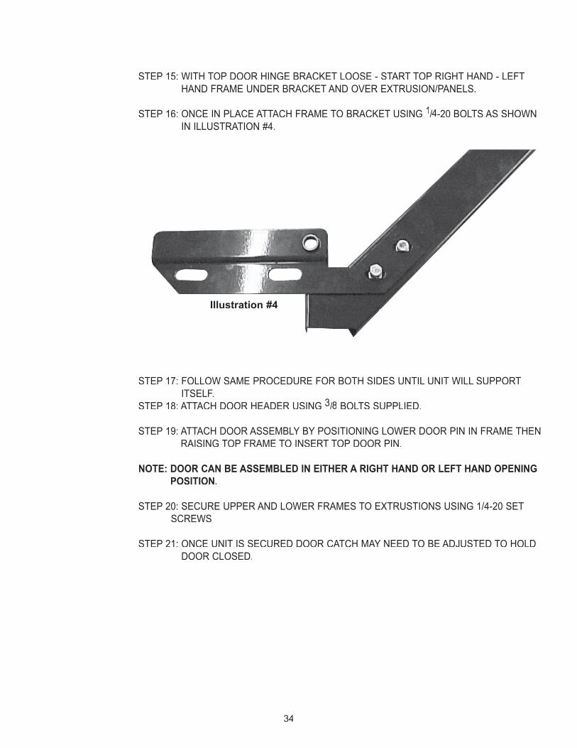
STEP 15: WITH TOP DOOR HINGE BRACKET LOOSE - START TOP RIGHT HAND - LEFT HAND FRAME UNDER BRACKET AND OVER EXTRUSION/PANELS.
STEP 16: ONCE IN PLACE ATTACH FRAME TO BRACKET USING 1/4/4/ -20 BOLTS AS SHOWN IN ILLUSTRATION #4.
STEP 17: FOLLOW SAME PROCEDURE FOR BOTH SIDES UNTIL UNIT WILL SUPPORT ITSELF.
STEP 18: ATTACH DOOR HEADER USING 3/8/8/ BOLTS SUPPLIED.
STEP 19: ATTACH DOOR ASSEMBLY BY POSITIONING LOWER DOOR PIN IN FRAME THEN RAISING TOP FRAME TO INSERT TOP DOOR PIN.
NOTE: DOOR CAN BE ASSEMBLED IN EITHER A RIGHT HAND OR LEFT HAND OPENING POSITION.
STEP 20: SECURE UPPER AND LOWER FRAMES TO EXTRUSTIONS USING 1/4-20 SET SCREWS
STEP 21: ONCE UNIT IS SECURED DOOR CATCH MAY NEED TO BE ADJUSTED TO HOLD DOOR CLOSED.
Illustration #4

35
LIMITED WARRANTYHeartland Tanning, Inc. warrants its products to be free from defects in materials and workmanship under intended normal use as described in the unit’s Operation and Instruction Manual, for a period of five (5) years from date of sale.
This Limited Warranty applies only to the original purchaser of the equipment through Heartland Tanning, Inc. or its authorized dealer or distributor, and is not transferable.
Heartland Tanning, Inc.’s obligations under this warranty are limited to repair or replacement of any defec-tive part without charge for that part to the original purchaser, with the following exceptions:
A. Tanning lamps are warranted against defects for a period of sixty (60) days from date of sale. B. Five (5) year Limited Warranty on parts. Only parts obtained through Heartland Tanning, Inc.,
its authorized dealers or distributors may be used. Transportation cost for parts shipped to the consumer and the return of defective parts to Heartland Tanning, Inc. are not included
C. Labor will be furnished without charge for one hundred eighty (180) days from the date of purchase only. All labor and related charges must be authorized by Heartland Tanning, Inc. prior to start of repairs, and must coincide with Heartland Tanning, Inc. established rates and time allotment policy.
D. All fans are warranted against defects for a period of five (5) years from date of sale. E. Timer system warranted for one (1) year. F. Acrylic, warranted for twelve (12) months prorated. G. Springs warranted for twelve (12) months.
H. Filter Glass warranted for twelve (12) months.
It is imperative that the original customer completes and returns the enclosed warranty card within ten (10) days after purchase to insure valid registration and coverage for potential claims.
If the warranty card is not registered, proof of purchase from Heartland Tanning, Inc. or its authorized dealer or distributor will be required prior to any consideration on warranty claims. This could result in service delays.
This warranty is extended to the individual or legal entity, whose name appears on the warranty registration card filed with Heartland Tanning, Inc., or whose name appears on the original sale document and may not be transferred to any other individual or legal entity.
This warranty does not apply to any failure of the product or any parts of the product due to alterations, modifications, misuse, abuse, accident, improper maintenance, improper installation or if the serial number on the product has been removed, altered, or defaced. Adequate packaging must be used for returned goods to prevent freight damage.
THIS WARRANTY IS EXPRESSLY IN LIEU OF ALL OTHER WARRANTIES, EXPRESSED OR IMPLIED, INCLUDING THE WARRANTIES OF MERCHANTABILITY AND HEARTLAND TANNING, INC. NO PERSON, FIRM OR CORPORATION IS AUTHORIZED TO OBLIGATE HEARTLAND TANNING, INC. FOR ANY LIABILITY IN CONNECTION WITH THE SALE OR USE OF THESE GOODS.
This warranty gives you specific legal rights, and you may also have other rights which vary from state to state.
NOTICE: Any misuse, abuse, modifications, alteration, improper installation, etc. of this product or its intended use will subject said party to direct responsibility for any and all consequences resulting from such action. Furthermore,
such actions will void all warranties and may relieve Heartland Tanning, Inc. of any liabilities relating to said product.