Embed Size (px)
Citation preview

MAX— 1
Owner / Operator’s Manual
Spreaders for Snow & Ice Control FOR MODEL
This Manual Must Be Read Before Operating The Equipment
CUSTOMER COPYWarren, Michigan 48089
800-800-800-725-8377725-8377725-8377
© © TTrrynex ynex InternaInternational tional 2009 20 L1218
Protected by the following patents, #6,089,478, #6,088,865, #Des.425,915 and other pending U.S. and foreign patent applications.
See Back Page for Details!
Warm Up to
with a
Winter Band!F R E EF R E E
SP-9300
Rev. 02

© Trynex International 2009 L1218MAX — 2
Table of Contents
Introduction . . . . . . . . . . . . . . . . . . . . . . . . . . . . . . . . . . . . . . . . . . . . . . . . . . . . . . . . . . . . . . . . . . . . . . . . . . . . . . . . . . . . . . . . . . . . . 3
General Information and Registration . . . . . . . . . . . . . . . . . . . . . . . . . . . . . . . . . . . . . . . . . . . . . . . . . . . . . . . . . . . . . . . . . . . . . . . . . . . . . . 4
Safety Information . . . . . . . . . . . . . . . . . . . . . . . . . . . . . . . . . . . . . . . . . . . . . . . . . . . . . . . . . . . . . . . . . . . . . . . . . . . . . . . . . . . . . . . . 5 - 7
Spreader Assembly and Exploded Views . . . . . . . . . . . . . . . . . . . . . . . . . . . . . . . . . . . . . . . . . . . . . . . . . . . . . . . . . . . . . . . . . . . . . . . . 8 - 17
Wiring Instructions . . . . . . . . . . . . . . . . . . . . . . . . . . . . . . . . . . . . . . . . . . . . . . . . . . . . . . . . . . . . . . . . . . . . . . . . . . . . . . . . . . . . . . . . 18
Electrical System Information . . . . . . . . . . . . . . . . . . . . . . . . . . . . . . . . . . . . . . . . . . . . . . . . . . . . . . . . . . . . . . . . . . . . . . . . . . . . . . . 19 - 22
Spreader Mounting System . . . . . . . . . . . . . . . . . . . . . . . . . . . . . . . . . . . . . . . . . . . . . . . . . . . . . . . . . . . . . . . . . . . . . . . . . . . . . . . . 23 - 25
Spreader Operating Information . . . . . . . . . . . . . . . . . . . . . . . . . . . . . . . . . . . . . . . . . . . . . . . . . . . . . . . . . . . . . . . . . . . . . . . . . . . . . 26 - 30
Troubleshooting Information . . . . . . . . . . . . . . . . . . . . . . . . . . . . . . . . . . . . . . . . . . . . . . . . . . . . . . . . . . . . . . . . . . . . . . . . . . . . . . . 31 - 33
Spreader Maintenance . . . . . . . . . . . . . . . . . . . . . . . . . . . . . . . . . . . . . . . . . . . . . . . . . . . . . . . . . . . . . . . . . . . . . . . . . . . . . . . . . . . . . . . 34
Determine Vehicle Payload Chart . . . . . . . . . . . . . . . . . . . . . . . . . . . . . . . . . . . . . . . . . . . . . . . . . . . . . . . . . . . . . . . . . . . . . . . . . . . . . . . 35
Blank and Note Pages . . . . . . . . . . . . . . . . . . . . . . . . . . . . . . . . . . . . . . . . . . . . . . . . . . . . . . . . . . . . . . . . . . . . . . . . . . . . . . 36 - 37
Warranty . . . . . . . . . . . . . . . . . . . . . . . . . . . . . . . . . . . . . . . . . . . . . . . . . . . . . . . . . . . . . . . . . . . . . . . . . . . . . . . . . . . . . . . . . . 38 - 39
Have a question or need assistance?
SnowEx Customer Service(800) 725-8377
or (586) 756-6555
Monday through Friday 8:00 AM to 4:30 PM EST
Fax: (586) 427-0552
E-Mail: [email protected]
Website: www.snowexproducts.com
Rev. 02

© Trynex International 2009 L1218 MAX — 3
Introduction
This manual has been designed for your help. It will assist you and instruct you on the proper set-up, installation and use of this spreader.Refer to the table of contents for an outline of this manual.
We require that you read and understand the contents of this manual completely (especially all safety information) beforeattempting any procedure contained herein.
THIS SIGN SHOULD ALERT YOU: The Society of Automotive Engineers has adopted this SAFETY ALERT SYMBOL to pinpoint characteristics that, if NOT carefully followed, can create a safety hazard. When you see this symbol in this manual or on the machine itself, BE ALERT! Your personal safety and the safety of others is involved.
Defined below are the SAFETY ALERT messages and how they will appear in this manual:
(RED)Information that, if not carefully followed,can cause death!
(ORANGE)Information that, if not carefully followed,can cause serious personal injury or death!
(YELLOW)Information that, if not carefully followed,can cause minor injury or damage to equipment.
Rev. 02

L1218 © Trynex International 2009 MAX — 4
General Information
CONGRATULATIONS!
The spreader you have purchased is an example of snow and ice control technology at its finest! Your spreader’s innovative, self-contained design is a trademark of all Trynex products. Here’s why...
SIMPLICITY: Fewer moving parts manufactured of higher quality means minimal maintenance for your SnowEx spreader.
RELIABILITY: High impact linear low density polyethelyne hopper, state-of-the-art electronic dual variable speed control, custom engineered powder coated frame, maximum torque 12 volt motor coupled to a custom engineered transmission found only on SnowEx products.
VERSATILITY: Multi-use capabilities allows spreading of a variety of materials for snow and ice control.
WARRANTY: Best in the industry, hands down! 2 Years Standard and now a 5 Year Extended (optional).
The benefits you are about to recognize are that of time, money and effort. We welcome you to the world of Trynex Performance.
Registration Record the following information in this manual for quick reference.
Spreader Model Number _____________________________________________________________________________________
Spreader Serial Number _______________________________ Controller Serial Number _______________________________
Date of Purchase ___________________________________________________________________________________________
Dealer Where Purchased _____________________________________________________________________________________
When ordering parts, the above information is necessary. This will help to insure that you receive the correct parts.
At the right is a diagram of the ID tag. This tag on the spreader is located on the frame.
Please fill out the warranty card with all the necessary information to validate it. This will also give us a record so that any safety or service information may be communicated to you.
Rev. 02

© Trynex International 2009 L1218 MAX — 5
Safety
Before attempting any procedure in this book, these safety instructions must be read and understood by all workers who have any part in the preparation or use of this equipment.
For your safety warning and information decals have been placed on this product to remind the operator of safety precautions . If anything happens to mark or destroy the decals, please request new ones from Trynex, International.
Unit must be strapped down and locked into position before operating vehicle.
Never exceed the Gross Vehicle Weight Rating of vehicle. Failure to do so may limit a vehicle’s handling characteristics.
Never attempt to take a unit off a truck with material in it.
Never exceed 45 m.p.h. when loaded spreader is attached to vehicle. Braking distances may be increased and handling characteristics may be impaired at speeds above 45 m.p.h.
Never allow children to operate or climb on equipment.Always check areas to be spread to be sure no hazardous conditions or substances are in the area.Always inspect unit for defects: broken, worn or bent parts, weakened areas on spreader or mount.
Always shut off vehicle and power source before attempting to attach or detach or service spreader unit. Be sure vehicle/power source is properly braked or chocked.
Always keep hands, feet, and clothing away from power-driven parts. Remember it is the owner’s responsibility to communicate information on safe usage and proper maintenance ofall equipment.
Always make sure personnel are clear of areas of danger when using equipment. Maintain 60' distance from all bystanders when operating the spreader.
Inspect the unit periodically for defects. Parts that are broken, missing, or worn out must be replaced immediately. The unit, or any part of it cannot be altered without prior written permission from the manufacturer.
Never use V-Maxx 9300 with foreign debris in the spreader. These units are designed to handle clean, free-flowing material.
Rev. 02

L1218 © Trynex International 2009MAX — 6
Safety
Always inspect pins and latches whenever attaching or detaching spreader, and beforetraveling.
Never leave material in hopper for long periods of time. Be aware that all ice melters are hygroscopic and will attract atmospheric moisture and harden up.
Remember, most accidents are preventable and caused by human error. Exercising of care and precautions must be observed to prevent the possibility of injury to operator orothers!
Never operate equipment when under the influence of alcohol, drugs, or medication that might alter your judgment and/or reaction time.
Before working with the spreader, secure all loose fitting clothing and unrestrained hair.
Always wear safety glasses with side shields when servicing spreader. Failure to do this could result in serious injury to the eyes.
Rev. 02

© Trynex International 2009 L1218 MAX— 7
D 6546
D 6548 D 6335 D 6544
D 6545D 6859
SERIAL NUMBERON REVERSE SIDE
Safety and Warning Labels Model # SP-9300
Rev. 02
L1218 © Trynex International 2009MAX— 8
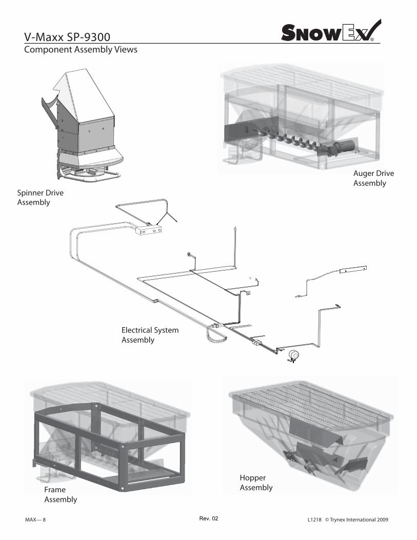
V-Maxx SP-9300 Component Assembly Views
Spinner Drive Assembly
Auger Drive Assembly
Electrical System Assembly
HopperAssemblyFrame
Assembly
Rev. 02

© Trynex International 2009 L1218 MAX — 9
THIS PAGE INTENTIONALLY LEFT BLANK
Rev. 02

L1218 © Trynex International 2009MAX — 10
Auger Drive Assembly Parts Breakdown Model # SP-9300
Rev. 02

© Trynex International 2009 L1218 MAX — 11
.ytQ noitpircseD .oN traP yeK 4 D6528 1/2”-13 Serrated Hex Head Bolt
Auger Drive Assembly Parts Breakdown Model # SP-9300
Auger Drive Assembly
D6814 Rear Bearing Cover Plate D6881 Rear Spinner Drive Mount
D6132 1/4”-20 x 3/4” Hex Head Bolt
D6159 10-32 x 2” HH Machine ScrewD6158 10-32 Lock NutD6845 Auger Bearing
D6166 5/16”-18 x 1” Hex Head Bolt
D6798 80” Auger WeldmentD6842
D6873 3/6” Keyway Stock
Transmission/Auger Coupler
D6843 Urethane Coupler SpyderINCLUDED Coupler Set Screw
D6894 Auger TransmissionD6825 Auger MotorD6877 #8 x 3/4” Driller With R-M WasherD6868 Auger Motor Cover
22
11
222122
1
131
2
1
16
D5706 5/16-18 Serrated Flange Nut
D6789 Auger Shaft Hopper Washer 1D6792 Auger Shaft Hopper Collar 1
Rev. 02

L1218 © Trynex International 2008MAX — 12
Spinner Drive Assembly Parts Breakdown Model # SP-9300
Rev. 02

© Trynex International 2009 L1218 MAX — 13
Spinner Drive Assembly Parts Breakdown Model # SP-9300
.ytQ noitpircseD .oN traP yeK
D6817 Spinner Shroud D6563 20” Drive Mounting Pin D4135 D6524 D6893 D6887 D6333D6731D6870D6452D6138D6854D6823D6133D6891D4289D6820D6833D6734
Drive Pin Clip5-16”-18 x 1-1/2” BoltSpinner Power PlugDirect Drive Spinner Motor3/16” Long Rivet5” Chute ExtensionSpinner Motor Cover3/8”-16 x 1” Serrated Type F5-16”-18 Nylock Nut1/4”-20 x 1” HWH Serrated SS5 Flite Urethane Spinner5-16”-18 x 1/2 “ Hex Head BoltSpinner Hub Weldment1/4” Nylock NutHeavy Duty Spinner Tubular GuardPlastic Spinner DeflectorExtended Plastic chute
1
11
12119118431115111
Complete Drive AssemblyA4052
D6859 Extended Plastic Spinner Guard 1
Rev. 02
L1218 © Trynex International 2009MAX — 14
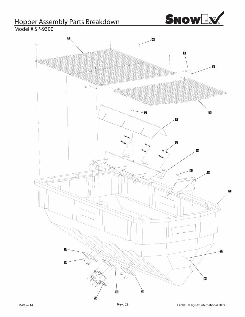
Hopper Assembly Parts Breakdown Model # SP-9300
Rev. 02

© Trynex International 2009 L1218 MAX — 15
Hopper Assembly Parts Breakdown Model # SP-9300
.ytQ noitpircseD .oN traP yeK 6799 D
6795 D D 6796
D 6866D 4134
D 6874 D 6138
D 6763 D 4122 D 6764
D 6811
D 4125D 6860D 6899D 4124
D 6869D 4121
9300 HopperTop Screen Front Section
Inverted-V Assembly
Inverted-V Backing Plates
3/8-16 x 1-1/2” HHCS
Salt Discharge Baffle
Heavy Duty Vibrator
1/4” x 1-1/2” Self Drilling Screw
3/8”-16 x 1” Hex Bolt
3/8” Flat Washer
11122
1011
811
Top Screen Rear SectionTop Screen Hinge PinTop Screen Hinge Pin Clip
5/16-18 Lock NutInverted-V Salt Baffle
3/8”-16 Nylock Nut
Vibrator Backing Plate
15
25111
Rev. 02

L1218 © Trynex International 2009 MAX — 16
Frame Assembly Parts Breakdown Model # SP-9300
Rev. 02

© Trynex International 2009 L1218 MAX — 17
Frame Assembly Parts Breakdown Model # SP-9300
Qty. .oN traP yeK Description
1
FrameAssembly
D 6797D 6765D 6884D 6880
9300 Frame Weldment
Auger Motor/Transmission SupportRear Apron With Light Hole Knock Outs
2Upper/Lower Front Rail 2
11
D 6528 1/2”-13 x 1” Serrated Hex Head Bolt 16
Rev. 02

L1218 © Trynex International 2009MAX — 18
Step 1: Take harness assembly and route from the rear of the vehicle to the front. Route harness along frame and attach to
frame hole and frame supports. It is not recommended to attach to fuel or brake lines for obvious reasons. Do not route close
to exhaust system or engine, even though Snowex uses high temperature wiring. It still could melt under extreme heat and short the
spreader electrical system, as well as the vehicle electrical system.
Step 2: Mount rear plug on bumper using supplied bolts, locate towards the center of the bumper to reduce the amount of
debris the tires will throw to the rear. Important: Apply a small amount of dielectric grease to the plug. Also try to mount so
plug faces upward to help keep plugs tightly sealed.
Step 3: Secure harness from the rear to the front using heavy duty ty-wraps or frame clips along the frame and lighter duty
ty-wraps everywhere else.
Step 4: Layout harness portion that connects to the battery along the fire wall and fender well. Do not connect power leads to
battery yet. Drill a 3/4" hole in the fire wall, or use existing access hole, for the control portion of the harness and route
connector and harness through hole. Be sure to check the area on the other side of the fire wall to make sure you are not
drilling into the vehicle harness or a control module. Generally you can drill on either side of the steering wheel for a goodlocation.
Step 4A: The power harness from control box to battery will need to be routed from the inside of the cab to the battery – this
results from the large high amperage connector. Route leads with lugs to battery — do not connect power at this time.
Step 5: Connect harness to the back of the controller and mount to a suitable location. NOTE: You may want to contact
customer before mounting controller as some prefer not to have holes drilled into the dashboard. Ty-wrap loose controller
harness and move to the engine compartment. Do not mount close to any heater vents.
Step 6: Connect power leads to the battery: Red + Positive, Black – Negative, always connect to the primary battery if using a dual
battery system. Secure loose loom to any other large or medium vehicle harness with medium duty ty-wraps; this will securewiring harness.
Step 7: Push the ON/OFF button on the controller to check for power ; when that has been confirmed, turn power OFF. The electrical
portion of the installation is complete.
Model # SP-9300Vehicle Harness Wiring Instructions
Rev. 02

© Trynex International 2009 L1218 MAX — 19
Electrical System Parts Breakdown Model # SP-9300
.ytQ noitpircseD .oN traP yeK 4 r (not shown) ehsaW 01# 6316 D 4 t (not shown)uN kcoL 01# 8516 D D 6874 D 6514 CHMSL Light Assembly 1 D 6529 #10 Machine Screw (not shown) 2 D 5716 V-Maxx Dual Control 1 D 6836 27' Vehicle Harness 1 D 6837 Control Power Cable 1 D 6895 Spreader Harness 1 D 6839 6 GA. Breaker Wire 1 D 6851 100 AMP Resetable Breaker 1
#14 x 1.5" HWH Screw (not shown) 4
1 p Light Kit/Spreader aC tsuD 1486 D
D 6784 Work light 1 D 6785 Work light Spreader Harness 1 D 6118 Spreader Spinner Dust Cap 1 D 6786 Light Kit Vehicle Harness W/Switch 1
IMPORTANT: Do not modify harness length. Any
and put in a cool dry place. The interior summer temperatures could damage circuit board andvoid warranty.
Anderson Block
D 6841 Light Kit Vehicle Harness W/Switch 1 D 6170 Anderson Connector With Leads 1
Rev. 02

L1218 © Trynex International 2009MAX — 20
Controller Wiring Diagram
BlackNegative (–)
VibratorRed Positive (+)
VibratorBlack Negative (–)
SpinnerRed Positive (+)
SpinnerBlack Negative (–)
MAIN INPUTPOWER
OUTPUT
RedPositive (+)
AugerBlack Negative (–)
AugerRed Positive (+)
20 AmpCircuit Breaker
Pre-Wetting SystemOutput Data Port
20
Connect to control mating half
PositiveWhite with Red Tracer (+) to batteryRing Terminal
NegativeBlack (–) to batteryRing Terminal
* NOTE:
A) Leads must only be attached to battery.
B) 100 Amp breaker must be inserted.
D6837 Control Power Cable with D6840 Breaker
Key Part No. Description Qty. D 6837 Control Power Cable 1 D 6839 6 GA. Breaker Wire 1 D 6840 100 AMP Resetable Breaker 1
Model # SP-9300
IMPORTANT: In the off season remove controland put in a cool dry place. The interior summer temperatures could damage circuit board andvoid warranty.
Rev. 02

© Trynex International 2009 L1218 MAX— 21
Spreader Power Harness Circuit Diagram Model # SP-9300
AUGERBlack Negative (–)
MAIN POWER PLUGSPREADER
AUGERRed Positive (+)
SPINNERRed Positive (+) SPINNER
Black Negative (–)
VIBRATORBlack Negative (–)
VIBRATORRed Positive (+)
RedPositive (+)
BlackNegative (–)
VIBRATOR POWER PLUG SPINNER
POWER PLUG
BlackNegative (–)
RedPositive (+)
Rev. 02

L1218 © Trynex International 2009MAX — 22
Vehicle Harness Circuit Diagram Model # SP-9300
VIBRATORYellow Positive (+)
VIBRATORGreen Negative (–)
SPINNEROrange Negative (–)
SPINNERBlue Positive (+)AUGER
Red Positive (+)
AUGERBlack Negative (–)
Red Positive (+)
Black Negative (–)
Anderson Block (2) Pos
Anderson Block (4) Pos
VIBRATOR OUTPUTYellow Positive (+)
VIBRATOR OUTPUTGreen Negative (–)
SPINNER OUTPUTBlue Positive (+)
SPINNER OUTPUTOrange Negative (–)
BUMPERPLUG
CONTROLOUTPUT PLUG
SPINNER/VIBRATORCIRCUIT
AUGERCIRCUITOUTPUT
* NOTE: Reference Bumper Plug for Color Code
Rev. 02

© Trynex International 2009 L1218 MAX — 23
Figure 2: Frame Mounting Bolts
Mounting System IllustrationsModel # SP-9300
.ytQ noitpircseD .oN traP yeK
D 4116 1/2”-13 x1-1/2” Hex Bolt 8
D 6756 Rear Stop Bracket, Right D 6755 Rear Stop Bracket, Left
Front Stop Bracket, LeftFront Stop Bracket, Right
tuN kcoL "2/1 0214 D
D 4121 3/8”-16 x 1” Hex Bolt
tuN kcoL "8/3 4214 D
Ratchet Strap (4PK)
Hardware Kit, HMK-175
7586 D
Flat Washer
8 1
4 4
8
1111
Figure 1
D 6759 D 6760
Bolt Though Body Floor
Cross Front Straps As Shown
Rear Stop LT & RT
D 6522 Bungie Strap (set of 15) 1 D 6794 Tarp 1 F50086 1
Rev. 02

L1218 © Trynex International 2009MAX— 24
Mount Kit Mounting Instructions Model # HMK-175
Step 1: For dump trucks remove tailgate, and for platform bodies remove rear racks.
Step 2: Load spreader on to truck bed and mount spinner assembly.
Step 3: Slide spreader forward until deflector/chute assembly makes contact with vehicle. Then, slide spreader back approx. 1" to allow for proper clearance.
Step 4: Install rear stop bars using supplied hole patterns (see Fig.2). To achieve the best position, you may need to drill additional
(see Fig.2)
holes in bracket in order to properly position spreader.
Step 4-A: Install front stops using supplied hole patterns (see Fig.1). You will need to bolt through the body.
Step 5: Now that the spreader is positioned front to back, you will now center it left to right. Looking at the inside front and rear corner of the lower frame area, you will notice (4) holes in the bottom of the frame. Using a paint pen or similar marking device, markhole locations.
Step 6: Before drilling holes, look beneath the approximate area where each hole will be located. Make sure there are no vehicle components that will be in the path of the drill before doing this step. If there are interferences, you can relocate holes as needed making sure there are at least two forward and two rearward of the front to back centerline.
Step 7: Install and tighten all (4) bolts.
Step 8: Install ratchet straps (see V-Maxx 9300 Mounting System: Strapping Techniques). It is very important for everyone’s safety this strapping method be used as the standard mounting procedure. NOTE: (Do not use ratchet straps exclusively.)
Step 9: Connect the spreader power cord to vehicle main power plug mounted at rear of vehicle (see Electrical Installation).
Rev. 02
NOTE: Pay special attention when drilling or clamping dissimilar metals to aluminum bodies. Galvanic corrosion can occur if not handled properly. Contact vehicle manufacturer for recommended practices.

L1218 © Trynex International 2009 MAX— 25
Mounting InstructionsModel # SP-9300
Recommended Installation For Platform Bodies
Through FloorChain Tie Downs(6) Places
Weld On Stake Pockets (6) Places.or
Rev. 02
© Trynex International 2009 L1218MAX— 26
Operating the Spreader
PREPARATION
CAUTION – Sweep area clear of foreign objects or obstacles that could cause personal injury. Keep other persons, children,
or animals our of the area to be spread.
SPREADER LOADING
WARNING – Do not overload vehicle. Use chart below to calculate weight of material. Weights of material are an average for dry materials.
Material Weight Per Cubic Ft. Rock Salt 35-40 lbs. Sand/Salt Mix 95-120 lbs.
Be sure to comply with manufacturer’s maximum gross vehicle weight ratings.
Warning – Never leave material in hopper for long periods of time as salt is hygroscopic and will attract atmospheric moisture and harden up. When spreading sand mix, a 1:1 ratio for Sand/Salt mix is recommended to prevent thematerial from freezing.
SPREADING TIPS
Never exceed 10 m.p.h. when spreading.
For a wider pass, increase spinner speed.
For a heavier pass, drive slower, or increase auger speed.
Never operate spreader near pedestrians.
Spread ice melters with the storm to prevent unmanageable levels of ice.
Calculate spread pattern when near vegetation.
V-Maxx 9300 CONTROL OPERATION
The Dual Variable Speed Control has dual finger-tip dials for maximum performance, digital system status with warning protection and built-in vibrator switch.
To start, press power switch on controller and spreader will accelerate to speed set on spinner and auger dials.
To stop, press power switch on controller to off position.
Speed of auger and spinner may be adjusted separately to get desired flow and spread distance from spreader.
The Vibrator Switch is needed for dense material or to increase the flow to the auger. This eliminates bridging of material in hopper. In case spreader becomes jammed, it will go into an auto-reverse program to free itself. Auger display will show (AR)
while trying to clear obstruction.
Model # SP-9300
Rev. 02

L1218 © Trynex International 2009 MAX — 27
Model # SP-9300Operating the Spreader (continued)
WARNING PROTECTION If audible beeping occurs, read display to identify problem. If display reads “OL” (overload) or “OH” (overheat), shut
controller down and carefully clear jammed auger. If display reads “E1“ this means there is a dead short in system. Do not use until problem is corrected. If display reads “E 0” this means that the motor is not getting any power. Check all connections If display reads “LB” the vehicle battery is extremely low (possibly caused by a poor or corroded connection) and could damage the system.
If there are any problems while operating the spreader, refer to Troubleshooting Guide.
AUTO-REVERSE “AR” FUNCTION If your controller displays “OL” this could indicate a jammed auger.
To engage the Auto-Reverse “AR” function:
Step 1: Shut the Main Power Switch OFF for 3 seconds.
Step 2: Turn the Main Power Switch ON. When the machine starts back up the “AR” sequence will automatically start and the auger will reverse for several rotations to clear the jam.
After a pause of several moments, the auger will automatically return to correct rotation.
If the jam is still not cleared, the controller will again display “OL”.
You may repeat Steps 1 & 2 for a second and third time.
If after the third try the controller displays “OL”, you must extract the material that is causing the problem.
Follow all warning directions when clearing jams.
Rev. 02

L1218 © Trynex International 2009 MAX — 28
Operating the Spreader (continued)
BAFFLE INSTRUCTIONS The V-Maxx SP-9300 uses a dual baffle design over the auger area.
This baffle (D6889) is used for dry bulk materials. The baffle is designed to reduce the risk of leakage with clean/dry free-flowing materials. If the material you are using is damp/wet, you may need to remove baffle (D6889). This will allow for more un-restricted flow of materials and possible bridging.
WARNING: Always disconnect power source before attempting to remove material baffle.
The main baffle assembly (D6889) must NEVER be removed from its original factory installed position unless the unit is being serviced or installing Optiflow Kit.
D6889
Model # SP-9300
Rev. 02

BAFFLE EXTENSION INSTRUCTIONS The Baffle Extension (D6776) is intended to be used with very dry
products that free-flow with little effort. The baffle is designed to keepthese types of materials from leaking out.
If you plan on using damp/wet materials, you should remove this baffle by removing the self-drilling screws.
If you are using a sand/salt mixture, remove baffle extension.
Key Part No. Description Qty D 6776 Salt Baffle Extension 1
D 6869 Discharge Baffle 1 D 6874 #14 x 1-1/2" TEK w/Neo Washer 2
© Trynex International 2009 L1218
Discharge Baffle Extension Instructions Model # SP-9300
MAX — 29Rev. 02

© Trynex International 2009 L1218MAX— 30
Center High Mount Stop Lamp (CHMSL)
With spreader mounted on vehicle, plug vehicle (CHMSL) harness into spreader stop lamp harness.
Using supplied harness clamps and screws, route harness along side wall lower corner or so that harness will be out of the way when spreader is in use.
Locate vehicle ground wire and stop lamp power wire at rear of vehicle. Use supplied wire taps to connect harness to
vehicle electrical system. Once wire taps are installed check to make sure stop lamp works when brake pedal is pressed. Properly complete installation by tying up any loose wires with ty-wraps. Add electrical tape over both connections
Model # SP-9300
to insure a solid electrical connection. Some newer trucks have auxiliary stop lamp power leads already at the rear for these types of applications.
CHMSL Spreader Harness(installed on Spreader from factory)
Key Part No. Description Qty. D 6158 #10 Lock Nut 2 D 6514 CHMSL Spreader Harness 1 D 6529 #10 Black Oxide Screw 2
CONNECT TO SPREADER LIGHT HARNESS 2-CONDUCTOR PLUG
Rev. 02

© Trynex International 2009 L1218
Model # SP-9300
MAX — 31
Troubleshooting
Loose electrical connections.
Blown Fuse.
Motor Seized.
Jammed auger.
Poor electrical connections.
Electrical short.
Controller failure.
Empty hopper.
Wet material.
Frozen or coarse material.
Spinner not turning.
Auger loose on shaft.
Vibrator not working.
Jammed auger, overload shut down.
Short in system.
Motor is not getting power.
Vehicle battery is extremely low,or a poor connection exists.
Whenever service is necessary, your local SnowEx Dealer knows your Spreader best. Take your Spreader to your local dealer for any maintenance or service needs on your unit. If this is not possible, the Troubleshooting Guide below may assist you inidentifying the problem.
Warning: First read all warning instructions and safety messages before servicing your spreader.
Preliminary Checks Be sure all electrical connections are tight and clean. Be sure nothing is jammed in the hopper.
Motor doesn’t run.
Controller shut down.
Material not flowingfrom hopper.
Audible alarm beeping and display shows OL or OH.
Audible alarm beepingdisplay shows E1.
Audible alarm beepingdisplay shows EO.
Audible alarm beepingdisplay shows LB.
Check all connections.
Replace fuse.
Replace motor.
Carefully clear jammed material.
Clean or replace connectors.Use dielectric grease.
Check electrical connections.Check for bare wires.
Replace controller.
Fill hopper.
Replace with dry material.
Replace material.
Check drive assembly.
Tighten locking bolt on the side of the auger. There is a flat machined on the driver shaft. Align the auger with this flat and tighten the bolt.
Replace vibrator
Turn off for three seconds, then restart. If shut downcontinues, turn off controller. Clear debris and lumps fromauger areas.
Turn off. Do not use until problem is corrected.
Turn off. Check all connections.
Turn off. Charge battery.
PROBLEM POSSIBLE CAUSE SOLUTION
Rev. 02

© Trynex International 2008 L1218MAX — 32
Troubleshooting Model # SP-9300
SPREADERDOES NOT RUN
JAMMED MATERIAL
BAD MOTOR
CHECK WITH TEST KIT
BAD TRANSMISSION
CHECK WITH TEST KIT
CORROSION
BAD CONTROLLER
CHECK WITH TEST KIT
SPREADER UNPLUGGED
MOTOR POWER CORDDISCONNECTED
INSIDE DRIVE ASSEMBLY
BREAK INWIRING HARNESS
CHECK WITH TEST KIT
CORROSION
LOOSE CONNECTION
LOAD TEST BATTERY
REPLACEAFFECTED
COMPONENTS
BAD CONTROLLER
CHECK WITH TEST KIT
SWITCH OFF & ONFOR AUTO-REVERSE
FUNCTIONCLEAR JAM
TEST 4 TO 20 AMP DRAWNO LOAD GOOD
20+ AMP DRAWNO LOAD BAD
TEST TURN SHAFTBY HAND
SHOULD TURN FREELY
REPLACE ALLCORRODED
CONNECTIONS
PLUG IN SPREADER
OPEN ACCESS COVERAND PLUG TOGETHER
REPLACE HARNESS
REPLACE ALL CORRODEDCONNECTIONS
TIGHTEN OR REPLACE
REPLACE
DEFINITION:AMP DRAWTOO HIGH
DEFINITION:OPEN CIRCUIT BETWEEN
MOTOR AND CONTROLLER
BAD ELECTRICALCONNECTION
LOW BATTERYLESS THAN 12 VOLT
OUTPUT
DEAD SHORTIN MOTOR CIRCUIT
CHECK HARNESSFOR SPLICED IN
ACCESSORY
BAD CONTROLLER
CHECK WITH TEST KIT
CONTROLLER TURNS ONBEEP SHUTS OFF
DISPLAYS ERROR CODE
ON/OFF SWITCHLIGHTS NO DISPLAY
NOTHING HAPPENSNO DISPLAY
ON/OFF SWITCH WILLNOT LIGHT UP
OL CODE
EO CODE
LB CODE
E1 CODE
ALL OTHERCODES
CHECK POWERTO BLUE WIRE
CHECK POWER SOURCETO CONTROLLER
BAD CONTROLLER
CHECK WITH TEST KIT
DON'T FORGETUSE DIELECTRIC
GREASE
Rev. 02

© Trynex International 2008 L1218 MAX — 33
Troubleshooting Material Flow Model # SP-9300
* Spreader capable of speading most granular bulk material.
MATERIALFREE FLOWS
MATERIAL ISSUECHECK BAFFLELENGTH
18" CORRECT
MATERIAL ISSUECHECK BAFFLEPOSITION
SHOULD TOUCHHOPPER ON 3 SIDES
MATERIALDOES NOT FLOW MATERIAL ISSUE
AUGER RUNSPROPER DIRECTION
AUGER RUNSBACKWARDS
REPLACE VEHICLEHARNESS
CHECK CONNECTIONSAT AUGER MOTOR
FOR REVERSE POLARITY
POLARITY CORRECTREPLACE SPREADER
HARNESS
MATERIALOBSTRUCTION
REMOVEOBSTRUCTION
AUGER RUNSBACKWARDS
RUN 12 VOLT TOAUGER CIRCUIT ONSPREADER POWER CORD
TURN ONVIBRATOR
SLOW MATERIAL
FLOW
TURN ONVIBRATOR
INCREASE AUGER SPEED
MATERIAL ISSUE
Rev. 02

© Trynex International 2009 L1218MAX — 34
Spreader Maintenance
WARNING – When servicing is necessary, perform it in a protected area. Do not use power tools in rain or snow because of danger of electrical shock or injury. Keep area well lighted. Use proper tools. Keep the area of service clean to helpavoid accidents.
WARNING – Disconnect electricity to spreader before servicing.
CAUTION – The controller is a solid state electronic unit and is not serviceable. Any attempt to service will void warranty.
CAUTION – There are no serviceable parts in the motor/transmission assembly. Any attempt to service will void warranty.
CAUTION – When replacing parts use only original manufacturer’s parts. Failure to do so will void warranty.
Use dielectric grease on all electrical connections to prevent corrosion at the beginning and end of the season and each time plugs are disconnected.
Gently wash unit after each use to prevent material build-up and corrosion.
CAUTION – When pressure washing motor enclosure area, stay at least 36'' away from all electrical items.
Paint or oil all bare metal surfaces at the end of the season.
Apply small amount of light oil to latches as needed.
If motor cover is removed for any reason, use silicone sealant to ensure weather proofing of enclosure.
Grease bearings after every 20 hour’s use.
After first use, tighten all nuts and bolts on spreader and mount.
WARNING: Never remove spreader with material in hopper.
ATTENTION: Store control in cool dry place during the off season.
CAUTION – Spinner motor is not designed for continuous duty. Allow motor to cool between long cycle times.
CAUTION – Vibrator is not designed for continuous duty. Allow motor to cool between long cycle times.
CAUTION – Do not modify vehicle or spreader wiring harness. Doing so will void product warranty.
Model # SP-9300
Rev. 02
© Trynex International 2009 L1218 MAX— 34
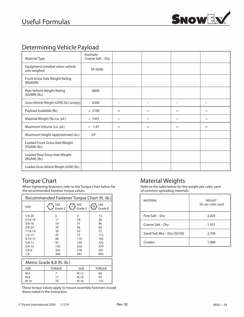
Useful Formulas
Material Type
Equipment installed when vehiclewas weighed
Front Gross Axle Weight Rating(RGAWR)
Rear Vehicle Weight Rating(GVWR) (lb.)
Gross Vehicle Weight (GVW) (lb.) (empty)
Payload Available (lb.)
Material Weight (lb./cu. yd.)
Maximum Volume (cu. yd.)
Maximum Height (approximate) (in.)
Loaded Front Gross Axle Weight(FGAW) (lb.)
Loaded Rear Gross Axle Weight(RGAW) (lb.)
Loaded Gross Vehicle Weight (GVW) (lb.)
Example:Coarse Salt – Dry
6'/8' Vee Pro
8600
– 6500
= 2100
÷ 1431
= 1.47
24"
–
=
÷
=
–
=
÷
=
–
=
÷
=
–
=
÷
=
Determining Vehicle Payload
Torque ChartWhen tightening fasteners, refer to the Torque Chart below for the recommended fastener torque values.
These torque values apply to mount assembly fasteners exceptthose noted in the instruction.
Recommended Fastener Torque Chart (ft.-lb.)
1/4-205/16-183/8-163/8-247/16-141/2-139/16-125/8-113/4-107/8-91-8
SIZESAEGrade 8
611192430456693150202300
91831465075110150250378583
1328466875115165225370591893
SAEGrade 5
SAEGrade 2
Metric Grade 8.8 (ft.-lb.)SIZE TORQUE SIZE TORQUE
M 6M 8M 10
71735
M 12M 14M 16
6095155
Material WeightsRefer to the table below for the weight per cubic yard of common spreading materials.
Fine Salt – Dry
Coarse Salt – Dry
Sand/Salt Mix – Dry (50/50)
Cinders
MATERIAL
2,025
1,431
2,700
1,080
WEIGHT (lb. per cubic yard)
SP-9300
Rev. 02

© Trynex International 2009 L1218MAX — 36
THIS PAGE INTENTIONALLY LEFT BLANK
Rev. 02

© Trynex International 2009 L1218 MAX — 37
NOTES: ______________________________________________________________
________________________________________________________________________________________________________
________________________________________________________________________________________________________
________________________________________________________________________________________________________
________________________________________________________________________________________________________
________________________________________________________________________________________________________
________________________________________________________________________________________________________
________________________________________________________________________________________________________
________________________________________________________________________________________________________
________________________________________________________________________________________________________
________________________________________________________________________________________________________
________________________________________________________________________________________________________
________________________________________________________________________________________________________
________________________________________________________________________________________________________
________________________________________________________________________________________________________
________________________________________________________________________________________________________
Rev. 02

L1218 © Trynex International 2008MAX — 38
Warranty
Limited Warranty
Snowex products are warranted for a period of two years from the date of purchase against defects in material or workmanship under normal use and service, subject to limitations detailed below. Warranty period of two years begins on the date of purchase by the original retail user.
The WARRANTY REGISTRATION CARD must be returned to the manufacturer for this warranty to become effective. This warranty applies to the original retail purchaser only. This warranty does not cover damages caused by improper installation, misuse, lack of proper maintenance, alterations or repairs made by anyone other than authorized Snowex dealers or Snowex personnel. Due to the corrosive properties of the materials dispensed by spreaders, Trynex does not warrant against damage caused by corrosion. Warranty claims by the user must be made to the dealer from where the product was purchased, unless otherwise authorized by Snowex. Snowex reserves the right to determine if any part is defective and to repair or replace such parts as it elects. This warranty does not cover shipping costs of defective parts to or from the dealer.
LIMITATION OF LIABILITY Neither Snowex, nor any company affiliated with it, makes any warranties, representations for promise as to the performance or quality other than what is herein contained. The liability of Snowex to the purchaser for damages arising out of the manufacture, sale, delivery, use or resale of this spreader shall be limited to and shall not exceed the costs of repair or replacement of defective parts. Snowex shall not be liable for loss of use, inconvenience or any other incidental, indirect or consequential damages, so the above limitations on incidental or consequential damages may not apply to you.
NO DEALER HAS AUTHORITY TO MAKE ANY REPRESENTATION OR PROMISE ON BEHALF OF SNOWEX, OR TO ALTER OR MODIFY THE TERMS OR LIMITATIONS OF THIS WARRANTY IN ANY WAY.
Rev. 02

© Trynex International 2009 L1218 MAX — 39
Warranty Registration and Customer Survey To initiate the warranty on your new SnowEx spreader and assure prompt warranty service, please complete the following warranty registration and customer survey, sign and mail it back to the factory within 30 days of purchase.
1) Date of Purchase:
2) Name:
Address:
Phone:
:rebmuN laireS:desahcruP ledoM xEwonS)3
4) Is this your first Trynex Spreader? Yes No
5) What type of vehicle are you using with your Spreader?
raeYledoMekaM
6) What type of material are you using in your spreader?
7) SnowEx Dealer Name:
SnowEx Dealer Address:
SnowEx Dealer Phone:
8) Does your Trynex Dealer stock Trynex replacement Parts? Yes No I don’t know
9) Do you feel your Trynex Dealer sold you the correct product for your needs/application? Yes No
10) How would you rate your overall satisfactionwith your SnowEx Dealer?
11) How would you rate your overall satisfaction with your SnowEx Product?
12) Would you purchase another Trynex Product?
13) If you would like to receive E-Mail ALERTS for new products, bulletins or special promotions please supply address : _________________________________________________
Yes No
14) Please use the space below to convey your comments and/or suggestions.
NOTE: I have read the owner’s manual and all safety precautions and I understand that this equipment could be dangerous if not operatedwith care and under the proper conditions.
15) Owner’s signature: X
VerySatisfied
VeryDissatisfiedSatisfied Dissatisfied
SomewhatSatisfied
SomewhatDissatisfied
VerySatisfied
VeryDissatisfiedSatisfied Dissatisfied
SomewhatSatisfied
SomewhatDissatisfied
PLEASE FOLD AND SEAL WITH TRANSPARENT TAPE BEFORE MAILING.
Rev. 02

23455 REGENCY PARK DR.WARREN MI 48089-2667
From:Postage
RequiredPost Office will
not deliverwithout proper
postage.
Simply Fill Out YourWarranty Registration and
Return It to the Factory!
Warm Up to
with a
Winter Band!F R E EF R E E
Rev. 02