Embed Size (px)
Citation preview
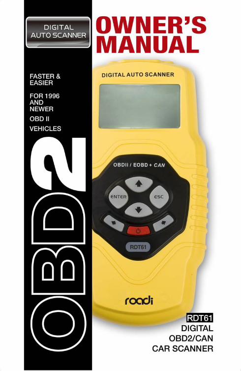
CHECKOWNER S MANUAL,
OBD2 CAR SCANNER2
Table of Contents
1. Safety Precautions and Warnings .................................................. 4
2. General Information............................................................................. 4 2.1 On-Board Diagnostics (OBD) II ......................................................... 4 2.2 Diagnostic Trouble Codes (DTCs)..................................................... 5 2.3 Location of the Data Link Connector (DLC) .................................... 6 2.4 OBD II Readiness Monitors ................................................................ 7 2.5 OBD II Monitor Readiness Status ...................................................... 8 2.6 OBD II Definitions ................................................................................ 8 2.7 Diagnostic Interface ............................................................................ 8
3. Using the scan tool ............................................................................ 10 3.1 Tool Description ................................................................................. 10 3.2 Specifications...................................................................................... 11 3.3 Accessories Included ....................................................................... 12 3.4 Navigation Characters ...................................................................... 12 3.5 Keyboard ........................................................................................... 12 3.6 Power ................................................................................................. 12 3.7 DTC Lookup ...................................................................................... 13 3.8 Product Setup .................................................................................... 14 3.9 Tool Information ................................................................................ 21 3.10 Battery Replacement ..................................................................... 21 3.11 Vehicle Coverage ........................................................................... 22 3.12 Product Troubleshooting ................................................................ 22
4. Review Data ........................................................................................ 23
5. OBD II Diagnostics ........................................................................... 25 5.1 Reading Codes ................................................................................. 27 5.2 Erasing Codes ................................................................................. 29 5.3 Live Data .......................................................................................... 31 5.4 Viewing Freeze Frame Data .......................................................... 44 5.5 Retrieving I/M Readiness Status .................................................... 46 5.6 O2 Monitor Test ............................................................................... 48 5.7 On-Board Monitor Test ................................................................... 50 5.8 Component Test ............................................................................... 52 5.9 Viewing Vehicle Information ............................................................. 53 5.10 Modules Present ............................................................................. 55
6. Appendix .............................................................................................. 56
CHECK OWNER S MANUAL,
OBD2 COAR SCANNER3
6.1 Appendix 1--PID List ......................................................................... 56 6.2 Appendix 2--In-Use Performance Tracking Data List..................... 60
7. Warranty and Service ........................................................................ 63 7.1 Limited One Year Warranty .............................................................. 63 7.2 Service Procedures........................................................................... 63
CHECKOWNER S MANUAL,
OBD2 CAR SCANNER4
1. Safety Precautions and Warnings To prevent personal injury or damage to vehicles and/or the scan tool, read this instruction manual first and observe the following safety precautions at a minimum whenever working on a vehicle:
1. Always perform automotive testing in a safe environment.
2. Wear safety eye protection that meets ANSI standards.
3. Keep clothing, hair, hands, tools, test equi pment, etc. away from all moving or hot engine parts.
4. Operate the vehicle in a well ventilated work area: Exhaust gases are poisonous.
5. Put blocks in front of the drive wheels and never leave the vehicle unattended while running tests.
6. Use extreme caution when working around the ignition coil, distributor cap, ignition wires and spark plugs. These components create hazardous voltages when the engine is running.
7. Put the transmission in PARK (for automatic transmission) or NEUTRAL (for manual transmission) and make sure the parking brake is engaged.
8. Keep a fire extinguisher suitable for gasoline/chemical/electrical fires nearby.
9. Don't connect or disconnect any test equipment while the ignition is on or the engine is running.
10. Keep the scan tool dry, clean, free from oil/water or grease. Use a mild detergent on a clean cloth to clean the outside of the scan tool, when necessary.
2. General Information
2.1 On-Board Diagnostics (OBD) II
The first generation of On-Board Diagnostics(called OBDI) was developed by the California Air Resources Board (ARB) and implemented in 1988 to monitor some of the emission control components on vehicles.
CHECK OWNER S MANUAL,
OBD2 COAR SCANNER5
As technology evolved and the desire to improve the On-Board Diagnostic system increased, a new generation of On-Board Diagnostic system was developed. This second generation of On-Board Diagnostic regulations is called "OBDII".
The OBDII system is designed to monitor emission control systems and key engine components by performing either continuous or periodic tests of specific components and vehicle conditions. When a problem is detected, the OBDII system turns on a warning lamp (MIL) on the vehicle instrument panel to alert the driver typically by the phrase of "Check Engine"”or "Service Engine Soon". The system will also store important information about the detected malfunction so that a technician can accurately find and fix the problem. Here below follow three pieces of such valuable information:
1) Whether th Malfunction Indicator Light (MIL) is commanded 'on' or 'off';
2) Which, if any, Diagnostic Trouble Codes (DTCs) are stored;
3) Readiness Monitor status.
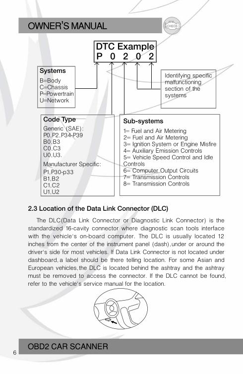
2.2 Diagnostic Trouble Codes (DTCs) OBD II Diagnostic Trouble Codes are codes that are stored by the on-board computer diagnostic system in response to a problem found in the vehicle. These codes identify a particular problem area and are intended to provide you with a guide as to where a fault mig ht be occurring within a vehicle. OBDII Diagnostic Trouble Codes consist of a five-digit alphanumeric code. The first character, a letter, identifies which control system sets the code. The other four characters, all numbers, provide additional information on where the DTC originated and the operating conditions that caused it to set. Here below is an example to illustrate the structure of the digits:
CHECKOWNER S MANUAL,
OBD2 CAR SCANNER6
DTC ExampleP 0 2 0 2
SystemsB=BodyC=Chassis P=Powertrain U=Network
Identifying specificmalfunctioning section of the systems
Code TypeGeneric (SAE):P0, P2, P34-P39B0, B3C0, C3U0, U3.
Manufacturer Specific:P1, P30-p33B1, B2C1, C2U1, U2
Sub-systems1= Fuel and Air Metering2= Fuel and Air Metering3= Ignition System or Engine Misfire4= Auxiliary Emission Controls5= Vehicle Speed Control and IdleControls6= Computer Output Circuits7= Transmission Controls8= Transmission Controls
2.3 Location of the Data Link Connector (DLC)
The DLC(Data Link Connector or Diagnostic Link Connector) is the standardized 16-cavity connector where diagnostic scan tools interface with the vehicle's on-board computer. The DLC is usually located 12 inches from the center of the instrument panel (dash), under or around the driver's side for most vehicles. If Data Link Connector is not located under dashboard, a label should be there telling location. For some Asian and European vehicles, the DLC is located behind the ashtray and the ashtray must be removed to access the connector. If the DLC cannot be found, refer to the vehicle's service manual for the location.
CHECK OWNER S MANUAL,
OBD2 COAR SCANNER7
2.4 OBD II Readiness Monitors An important part of a vehicle's OBD II system is the Readiness Monitors, which are indicators used to find out if all of the emissions components have been evaluated by the OBD II system. They are running periodic tests on specific systems and components to ensure that they are performing within allowable limits.
Currently, there are eleven OBD II Readiness Monitors (or I/M Monitors) defined by the U.S. Environmental Protection Agency(EPA). Not all monitors are supported by all vehicles and the exact number of monitors in any vehicle depends on the motor vehicle manufacturer's emissions control strategy.
Continuous Monitors -- Some of the vehicle components or systems are continuously tested by the vehicle's OBD II system, while others are tested only under specific vehicle operating conditions. The continuously monitored components listed below are always ready:
1. Misfire2. Fuel System3. Comprehensive Components (CCM)
Once the vehicle is running, the OBD II system is continuously checking the above components, monitoring key engine sensors, watching for engine misfire, and monitoring fuel demands.
Non-Continuous Monitors -- Unlike the continuous monitors, many emissions and engine system components require the vehicle to be operated under specific conditions before the monitor is ready. These monitors are termed non-continuous monitors and are listed below:
1). EGR System2). O2 Sensors3). Catalyst4). Evaporative System5). O2 Sensor Heater6). Secondary air7). Heated Catalyst8). A/C system
CHECKOWNER S MANUAL,
OBD2 CAR SCANNER8
2.5 OBD II Monitor Readiness Status
OBDII systems must indicate whether or not the vehicle's PCM's monitor system has completed testing on each component. Components that have been tested will be reported as "Ready", or "Complete", meaning they have been tested by the OBDII system. The purpose of recording readiness status is to allow inspectors to determine if the vehicle's OBD II system has tested all the components and/or systems.
The powertrain control module (PCM) sets a monitor to "Ready" or"Complete" after an appropriate drive cycle has been performed. The drive cycle that enables a monitor and sets readiness codes to "Ready" varies for each individual monitor. Once a monitor is set as "Ready" or "Complete", it will remain in this state. A number of factors, including erasing of diagnostic trouble codes (DTCs) with a scan tool or a disconne-cted battery, can result in Readiness Monitors being set to "Not Ready". Since the three continuous monitors are constantly evaluating, they will be reported as "Ready" all of the time. If testing of a particular supported non-continuous monitor has not been completed, the monitor status will be reported as "Not Complete" or "Not Ready".”
In order for the OBD monitor system to become ready, the vehicle should be driven under a variety of normal operating conditions. These operating conditions may include a mix of highway driving and stop and go, city type driving, and at least one overnig ht-off period. For specific information on getting your vehicle's OBD monitor system ready, please consult your vehicle owner's manual.
2.6 OBD II Definitions
Powertrain Control Module (PCM) -- OBD II terminology for the on-board computer that controls engine and drive train.
Malfunction Indicator Light (MIL) -- Malfunction Indicator Light (Service Engine Soon, Check Engine) is a term used for the light on the instrument panel. It is to alert the driver and/or the repair technician that there is a problem with one or more of vehicle's systems and may cause emissions to exceed federal standards. If the MIL illuminates with a steady lig ht, it indicates that a problem has been detected and the vehicle should be serviced as soon as possible. Under certain conditions, the dashboard
CHECK OWNER S MANUAL,
OBD2 COAR SCANNER9
DTC -- Diagnostic Trouble Codes (DTC) that identify which section of the emission control system has malfunctioned.
Enabling Criteria -- Also termed Enabling Conditions. They are the vehicle-specific events or conditions that must occur within the engine before the various monitors will set, or run. Some monitors require the vehicle to follow a prescribed "drive cycle" routine as part of the enabling criteria. Drive cycles vary among vehicles and for each monitor in any particular vehicle.
OBD II Drive Cycle -- A specific mode of vehicle operation that provides conditions required to set all the readiness monitors applicable to the vehicle to the "ready" condition. The purpose of completing an OBD II drive cycle is to force the vehicle to run its onboard diagnostics. Some form of a drive cycle needs to be performed after DTCs have been erased from the PCMs memory or after the battery has been disconnected. Running through a vehicle's complete drive cycle will set the readiness monitors so that future faults can be detected. Drive cycles vary depending on the vehicle and the monitor that needs to be reset. For vehicle specific drive cycle, consult the vehicle's Owner's Manual.
Freeze Frame Data -- When an emissions related fault occurs, the OBD II system not only sets a code but also records a snapshot of the vehicle operating parameters to help in identifying the problem. This set of values is referred to as Freeze Frame Data and may include important engine parameters such as engine RPM, vehicle speed, air flow, engine load, fuel pressure, fuel trim value, engine coolant temperature, ignition timing advance, or closed loop status.
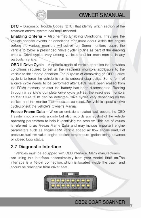
2.7 Diagnostic Interface Vehicles must be equipped with OBD Interface. Many manufacturersare using this interface approximately from year model 1995 on.The interface is a 16-pin connection, which is located inside the cabin and should be reachable from driver seat.
CHECKOWNER S MANUAL,
OBD2 CAR SCANNER10
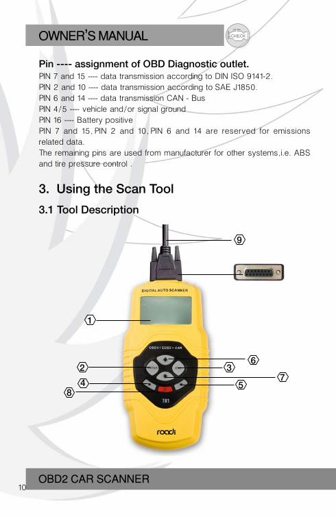
Pin ---- assignment of OBD Diagnostic outlet.PIN 7 and 15 ---- data transmission according to DIN ISO 9141-2.PIN 2 and 10 ---- data transmission according to SAE J1850.PIN 6 and 14 ---- data transmission CAN - BusPIN 4/5 ---- vehicle and/or signal groundPIN 16 ---- Battery positivePIN 7 and 15, PIN 2 and 10, PIN 6 and 14 are reserved for emissions related data.The remaining pins are used from manufacturer for other systems, i.e. ABS and tire pressure control .
3. Using the Scan Tool
3.1 Tool Description
63
75
1
2
48
9
CHECK OWNER S MANUAL,
OBD2 COAR SCANNER11
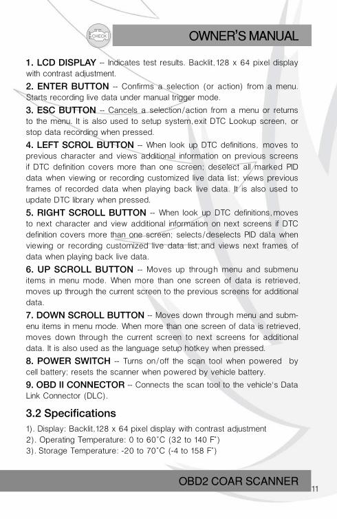
1. LCD DISPLAY -- Indicates test results. Backlit, 128 x 64 pixel display with contrast adjustment.
2. ENTER BUTTON -- Confirms a selection (or action) from a menu. Starts recording live data under manual trigger mode.
3. ESC BUTTON -- Cancels a selection/action from a menu or returns to the menu. It is also used to setup system, exit DTC Lookup screen, or stop data recording when pressed.
4. LEFT SCROL BUTTON -- When look up DTC definitions, moves to previous character and views additional information on previous screens if DTC definition covers more than one screen; deselect all marked PID data when viewing or recording customized live data list; views previous frames of recorded data when playing back live data. It is also used to update DTC library when pressed.
5. RIGHT SCROLL BUTTON -- When look up DTC definitions, moves to next character and view additional information on next screens if DTC definition covers more than one screen; selects/deselects PID data when viewing or recording customized live data list, and views next frames of data when playing back live data.
6. UP SCROLL BUTTON -- Moves up through menu and submenu items in menu mode. When more than one screen of data is retrieved, moves up through the current screen to the previous screens for additional data.
7. DOWN SCROLL BUTTON -- Moves down through menu and subm-enu items in menu mode. When more than one screen of data is retrieved, moves down through the current screen to next screens for additional data. It is also used as the language setup hotkey when pressed.
8. POWER SWITCH -- Turns on/off the scan tool when powered by cell battery; resets the scanner when powered by vehicle battery.
9. OBD II CONNECTOR -- Connects the scan tool to the vehicle's Data Link Connector (DLC).
3.2 Specifications1). Display: Backlit, 128 x 64 pixel display with contrast adjustment2). Operating Temperature: 0 to 60°C (32 to 140 F°)3). Storage Temperature: -20 to 70°C (-4 to 158 F°)
CHECKOWNER S MANUAL,
OBD2 CAR SCANNER12
4). External Power: 8.0 to 18.0 V power provided via vehicle battery5). Internal Power: 9V cell battery6). Dimensions: Length Width Height 209 mm (7.00”) 107 mm (3.74”) 37 mm (1.38”)7). NW: 0.76kg (0.84lb), GW: 0.98 kg(1.21lb
3.3 Accessories Included1). User's Manual -- Instructions on tool operations.2). CD -- Includes user’s manual, DTC lookup software, and etc.3). OBD2 cable -- Provides power to tool and communicates between tool and vehicle.4). USB cable--Used to upgrade the scan tool, and to print retrieved data.5). Carry case -- A nylon case to store the scan tool when not in use.
3.4 Navigation Characters
Characters used to help navigate the scan tool are:
1). " " -- Indicates current selection.2). " "-- A"DOWN" Arrow indicates additional information is available on next screens.3). " "-- An "UP" Arrow indicates additional information is available on previous screens.4). "$" -- Identifies the control module number from which data is retrieved.5). "G" -- Indicates graphic viewing is available.
3.5 Keyboard No solvents such as alcohol are allowed to clean the keypad or display. Use a mild nonabrasive detergent and a soft cotton cloth. Do not soak the keypad as the keypad is not waterproof.
3.6 PowerInternal Battery Power
The scan tool can be inserted a 9V cell battery that provides power for
CHECK OWNER S MANUAL,
OBD2 COAR SCANNER13
off-car reviewing and analysis. Press the power key to turn on the scan tool. When the icon appears, replace the battery as instructed in Battery Replacement on paragraph 3.10.
If the scan tool is stored for a long period of time, remove batteries to prevent battery leakage from damaging battery compartment.
External Power
External power of the scan tool is provided via the vehicle Data LinkConnector (DLC). Just follow the steps below to turn on the scan tool:
1). Connect the OBD II Cable to scan tool.
2). Find DLC on vehicle.
A plastic DLC cover may be found for some vehicles and you need to remove it before plugging the OBD2 cable.
3). Plug OBD II cable to the vehicle's DLC.
3.7 DTC LookupThe DTC Lookup function is used to search for definitions of DTCs stored in built-in DTC library.
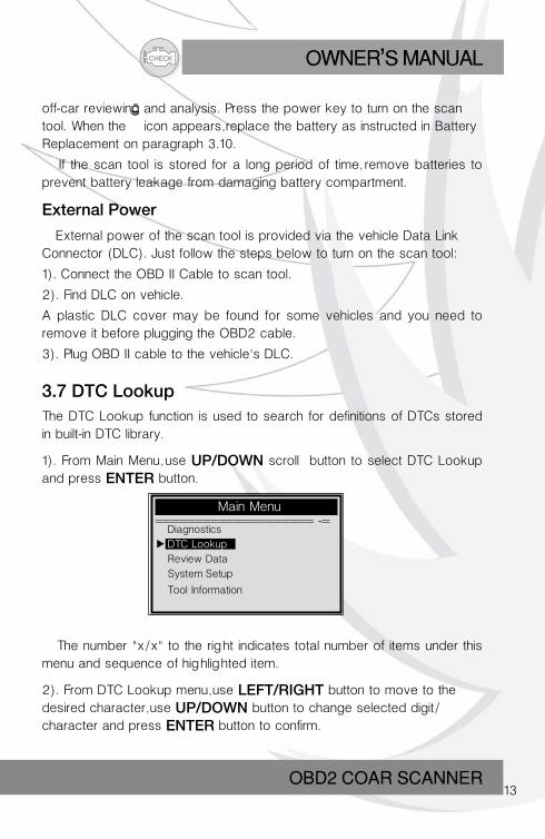
1). From Main Menu, use UP/DOWN scroll button to select DTC Lookup and press ENTER button.
The number "x/x" to the right indicates total number of items under this menu and sequence of highlighted item.
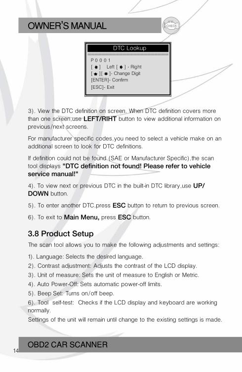
2). From DTC Lookup menu, use LEFT/RIGHT button to move to the desired character, use UP/DOWN button to change selected digit/character and press ENTER button to confirm.
Main Menu ==================== -=
Diagnostics
DTC Lookup
Review Data
System Setup
Tool Information
CHECKOWNER S MANUAL,
OBD2 CAR SCANNER14
DTC Lookup ======================= P 0 0 0 1
[ ] – Left [ ] - Right
[ ][ ]- Change Digit
[ENTER]- Confirm
[ESC]- Exit
3). View the DTC definition on screen. When DTC definition covers more than one screen, use LEFT/RIHT button to view additional information on previous/next screens.
For manufacturer specific codes, you need to select a vehicle make on an additional screen to look for DTC definitions.
If definition could not be found (SAE or Manufacturer Specific), the scan tool displays "DTC definition not found! Please refer to vehicle service manual!"
4). To view next or previous DTC in the built-in DTC library, use UP/DOWN button.
5). To enter another DTC, press ESC button to return to previous screen.
6). To exit to Main Menu, press ESC button.
3.8 Product SetupThe scan tool allows you to make the following adjustments and settings:
1). Language: Selects the desired language.
2). Contrast adjustment: Adjusts the contrast of the LCD display.
3). Unit of measure: Sets the unit of measure to English or Metric.
4). Auto Power-Off: Sets automatic power-off limits.
5). Beep Set: Turns on/off beep.
6). Tool self-test: Checks if the LCD display and keyboard are working normally.
Settings of the unit will remain until change to the existing settings is made.
CHECK OWNER S MANUAL,
OBD2 COAR SCANNER15
To enter the setup menu mode
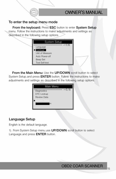
From the keyboard: Press ESC button to enter System Setup menu. Follow the instructions to make adjustments and settings as described in the following setup options.
System Setup ================= -=1/6
Language
Contrast
Unit of Measure
Auto Power-off
Beep Set
Tool Self-test
From the Main Menu: Use the UP/DOWN scroll button to select System Setup, and press ENTER button. Follow the instructions to make adjustments and settings as described in the following setup options.
Main Menu ================= -=5/6
Language Setup
English is the default language.
1). From System Setup menu, use UP/DOWN scroll button to select Language, and press ENTER button.
Diagnostics
DTC Lookup
Review Data
System Setup
Tool Information
CHECKOWNER S MANUAL,
OBD2 CAR SCANNER16
System Setup ================= -=1/6
Language ====================1/2
System Setup ==================-= 2/6
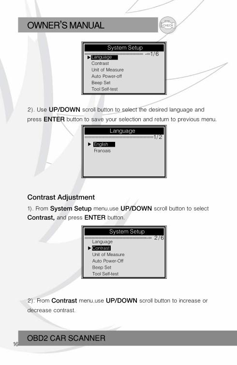
2). Use UP/DOWN scroll button to select the desired language and
press ENTER button to save your selection and return to previous menu.
Contrast Adjustment
1). From System Setup menu, use UP/DOWN scroll button to select
Contrast, and press ENTER button.
2). From Contrast menu, use UP/DOWN scroll button to increase or
decrease contrast.
Language
Contrast
Unit of Measure
Auto Power-off
Beep Set
Tool Self-test
English
Français
Language
Contrast
Unit of Measure
Auto Power-Off
Beep Set
Tool Self-test
CHECK OWNER S MANUAL,
OBD2 COAR SCANNER17
Contrast =======================
(30%)
Use to change
System Setup ========================-:3/6
Unit of Measure ========================-:2/2
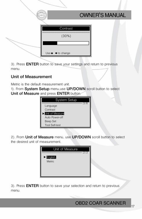
3). Press ENTER button to save your settings and return to previous menu.
Unit of Measurement
Metric is the default measurement unit.1). From System Setup menu, use UP/DOWN scroll button to select
Unit of Measure and press ENTER button.
2). From Unit of Measure menu, use UP/DOWN scroll button to select the desired unit of measurement.
3). Press ENTER button to save your selection and return to previous menu.
Language
Contrast
Unit of Measure
Auto Power-off
Beep Set
Tool Self-test
English
Metric
CHECKOWNER S MANUAL,
OBD2 CAR SCANNER18
System Setup ========================-:4/6
Auto Power-off =============================
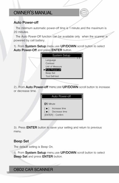
Auto Power-off
The minimum automatic power-off time is 1 minute, and the maximum is 20 minutes.
The Auto Power-Off function can be available only when the scanner is powered by cell battery.
1). From System Setup menu, use UP/DOWN scroll button to select
Auto Power-Off and press ENTER button.
2). From Auto Power-off menu, use UP/DOWN scroll button to increase or decrease time.
01 Minute
[ ] – Increase time
[ ] – Decrease time
[ENTER] - Confirm
3). Press ENTER button to save your setting and return to previous menu.
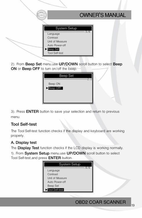
Beep Set
The default setting is Beep On.
1). From System Setup menu, use UP/DOWN scroll button to select
Beep Set and press ENTER button.
Language
Contrast
Unit of Measure
Auto Power-off
Beep Set
Tool Self-test
CHECK OWNER S MANUAL,
OBD2 COAR SCANNER19
System Setup ========================-:5/6
Beep Set ==========================2/2
System Setup ========================-:6/6
2). From Beep Set menu, use UP/DOWN scroll button to select Beep ON or Beep OFF to turn on/off the beep.
3). Press ENTER button to save your selection and return to previous
menu.
Tool Self-test
The Tool Self-test function checks if the display and keyboard are working properly.
A. Display testThe Display Test function checks if the LCD display is working normally.
1). From System Setup menu, use UP/DOWN scroll button to select Tool Self-test, and press ENTER button.
Language
Contrast
Unit of Measure
Auto Power-off
Beep Set
Tool Self-test
Beep ON
Beep OFF
Language
Contrast
Unit of Measure
Auto Power-off
Beep Set
Tool Self-test
CHECKOWNER S MANUAL,
OBD2 CAR SCANNER20
Tool Self-test ==========================1/2
Tool Self-test ==========================2/2
Keyboard Test =============================
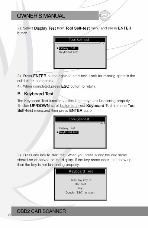
2). Select Display Test from Tool Self-test menu and press ENTER button.
3). Press ENTER button again to start test. Look for missing spots in the solid black characters.
4). When completed, press ESC button to return.
B. Keyboard Test
The Keyboard Test function verifies if the keys are functioning properly.1). Use UP/DOWN scroll button to select Keyboard Test from the Tool Self-test menu, and then press ENTER button.
2). Press any key to start test. When you press a key, the key nameshould be observed on the display. If the key name does not show up, then the key is not functioning properly.
Press any key to
start test
key:
Double [ESC] to return
Display Test
Keyboard Test
Display Test
Keyboard Test
CHECK OWNER S MANUAL,
OBD2 COAR SCANNER21
If you press and hold the power switch, the key name does not show on the screen, but resets the scanner when powered by vehicle battery, or turns off the scanner when powered by cell battery. If it does not restart the scanner or power off the scanner, the key is not working properly.3). Double press ESC to return to previous menu.
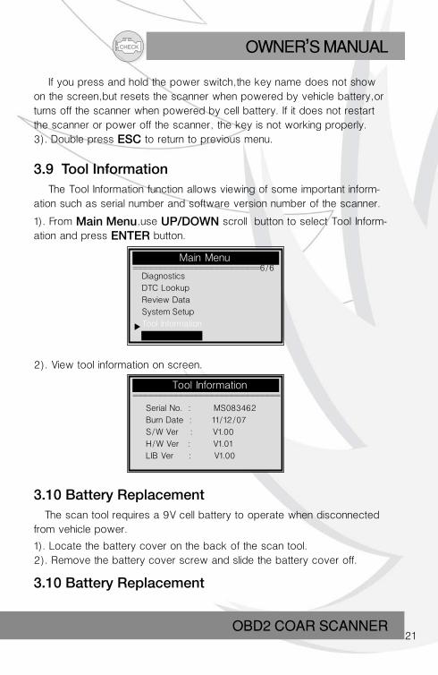
3.9 Tool Information The Tool Information function allows viewing of some important inform-ation such as serial number and software version number of the scanner.
1). From Main Menu, use UP/DOWN scroll button to select Tool Inform-ation and press ENTER button.
Main Menu =========================6/6
Tool Information =============================
2). View tool information on screen.
Serial No. : MS083462
Burn Date : 11/12/07
S/W Ver : V1.00
H/W Ver : V1.01
LIB Ver : V1.00
3.10 Battery Replacement The scan tool requires a 9V cell battery to operate when disconnected from vehicle power.
1). Locate the battery cover on the back of the scan tool.2). Remove the battery cover screw and slide the battery cover off.
3.10 Battery Replacement
Diagnostics
DTC Lookup
Review Data
System Setup
Tool Information
CHECKOWNER S MANUAL,
OBD2 CAR SCANNER22
The scan tool requires a 9V cell battery to operate when disconnected from vehicle power. 1). Locate the battery cover on the back of the scan tool.2). Remove the battery cover screw and slide the battery cover off.3). Remove discharged batteries and install a new 9V cell battery.4) Reinstall battery cover by sliding battery cover on and installing screw.
3.11 Vehicle Coverage This model T69 OBDII/EOBD Scanner is specially designed to work with all OBD II compliant vehicles, including those equipped with next-generation protocol -- Control Area Network (CAN). It is required by EPA that all 1996 and newer vehicles (cars and light trucks) sold in the United States must be OBD II compliant and this includes all Domestic, Asian and European vehicles.
A small number of 1994 and 1995 model year gasoline vehicles are OBD II compliant. To verify if a 1994 or 1995 vehicle is OBD II compliant, check the Vehicle Emissions Control Information (VECI) Label which is located under the hood or by the radiator of most vehicles.If the vehicle is OBD II compliant, the label will designate "OBDII Certified". Additionally, Government regulations mandate that all OBDII compliant vehicles must have a "common" sixteen-pin Data Link Connector (DLC).
3.12 Product TroubleshootingVehicle Linking Error
A communication error occurs if the scan tool fails to communicate with the vehicle's ECU (Engine Control Unit). You need to do the following to check up:
For your vehicle to be OBD II compliant it must have a 16-pin DLC(Data Link Connector) under the dash and the Vehicle Emission Control Information Label must state that the vehicle is OBD II compliant.
Verify the control module is not defective.
Verify that the ignition is ON;
CHECK OWNER S MANUAL,
OBD2 COAR SCANNER23
Check if the scan tool’s OBD II connector is securely connected to the vehicle's DLC; Verify that the vehicle is OBD2 compliant; Turn the ignition off and wait for about 10 seconds. Turn the ignition back to on and continue the testing.
Verify the control module is not defective.
Operating Error
If the scan tool freezes, then an exception occurs or the vehicle's ECU (Engine Control Unit) is too slow to respond to requests. You need to do the following to reset the tool: Press and hold POWER button for at least 2 seconds to reset the scan tool. Turn the ignition off and wait for about 10 seconds. Turn the ignition back to on and continue the testing.
Scan tool doesn’t power up
If the scan tool won’t power up or operates incorrectly in any other way, you need to do the following to check up: -Check if the scan tool’s OBD II connector is securely connected to the vehicle's DLC; -Check if the DLC pins are bent or broken. Clean the DLC pins if necessa-ry. -Check vehicle battery to make sure it is still good with at least 8.0 volts.
4. Review DataThe Review Data function allows viewing of data from last test recorded by the scan tool.
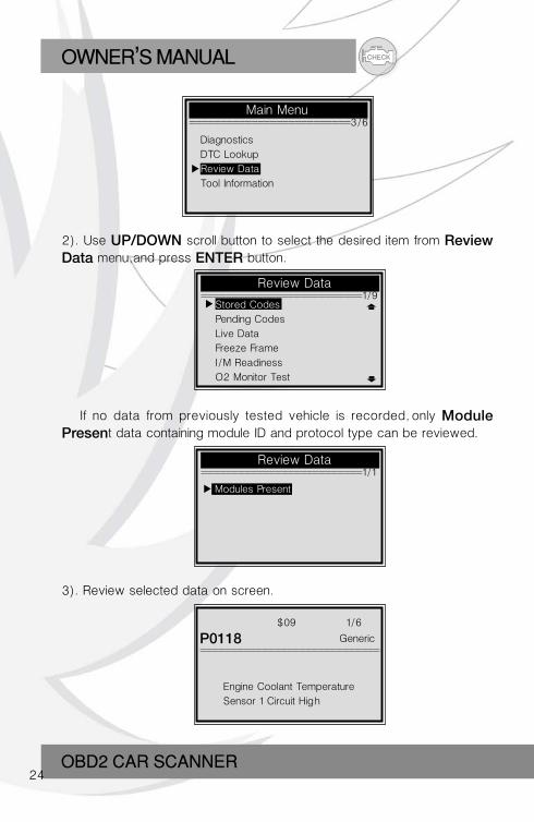
1). Use UP/DOWN scroll button to select Review Data from Main Menu, and press ENTER button.
CHECKOWNER S MANUAL,
OBD2 CAR SCANNER24
Review Data ==========================1/9
Review Data ==========================1/1
=============================
2). Use UP/DOWN scroll button to select the desired item from Review Data menu, and press ENTER button.
If no data from previously tested vehicle is recorded, only Module Present data containing module ID and protocol type can be reviewed.
3). Review selected data on screen.
$09 1/6
P0118 Generic
Engine Coolant Temperature
Sensor 1 Circuit High
Stored Codes
Pending Codes
Live Data
Freeze Frame
I/M Readiness
O2 Monitor Test
Modules Present
Main Menu ==========================3/6
Diagnostics
DTC Lookup
Review Data
Tool Information
CHECK OWNER S MANUAL,
OBD2 COAR SCANNER25
If there is no data stored for selected item, a "Not Supported or Stored No Data!" message shows on the screen.
5. OBD II Diagnostics When more than one vehicle control module is detected by the scan tool, you will be prompted to select the module where the data may be retrieved. The most often to be selected are the Powertrain Control Module [PCM] and Transmission Control Module [TCM].CAUTION: Don't connect or disconnect any test equipment with ignition on or engine running.
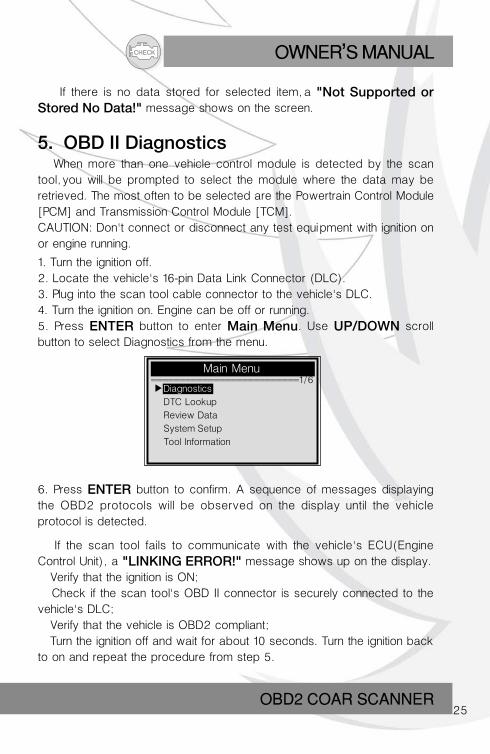
1. Turn the ignition off.2. Locate the vehicle's 16-pin Data Link Connector (DLC).3. Plug into the scan tool cable connector to the vehicle's DLC.4. Turn the ignition on. Engine can be off or running.5. Press ENTER button to enter Main Menu. Use UP/DOWN scroll button to select Diagnostics from the menu.
Main Menu ==========================1/6
Diagnostics
DTC Lookup
Review Data
System Setup
Tool Information
6. Press ENTER button to confirm. A sequence of messages displaying the OBD2 protocols will be observed on the display until the vehicle protocol is detected.
If the scan tool fails to communicate with the vehicle's ECU(Engine Control Unit), a "LINKING ERROR!" message shows up on the display. Verify that the ignition is ON; Check if the scan tool's OBD II connector is securely connected to the vehicle's DLC; Verify that the vehicle is OBD2 compliant; Turn the ignition off and wait for about 10 seconds. Turn the ignition back to on and repeat the procedure from step 5.
CHECKOWNER S MANUAL,
OBD2 CAR SCANNER26
Diagnostic =============================
System Status =============================
If the "LINKING ERROR" message does not go away, then there might be problems for the scan tool to communicate with the vehicle. Contact your local distributor or the manufacturer's customer service department for assistance.
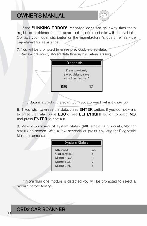
7. You will be prompted to erase previously stored data. Review previously stored data thoroughly before erasing.
Erase previously
stored data to save
data from this test?
YES NO
If no data is stored in the scan tool, above prompt will not show up.
8. If you wish to erase the data, press ENTER button; if you do not want to erase the data, press ESC or use LEFT/RIGHT button to select NO and press ENTER to continue.
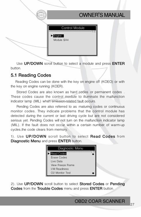
9. View a summary of system status (MIL status, DTC counts, Monitor status) on screen. Wait a few seconds or press any key for Diagnostic Menu to come up.
MIL Status ON
Codes Found 6
Monitors N/A 3
Monitors OK 3
Monitors INC 5
If more than one module is detected, you will be prompted to select a module before testing.
CHECK OWNER S MANUAL,
OBD2 COAR SCANNER27
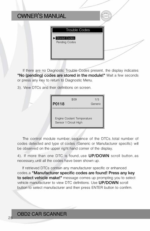
Control Module ==========================1/2
Engine
Module $A4
Diagnostic Menu ==========================1/11
Use UP/DOWN scroll button to select a module and press ENTER button.
5.1 Reading Codes Reading Codes can be done with the key on engine off (KOEO) or with the key on engine running (KOER).
Stored Codes are also known as hard codes”or permanent codes”. These codes cause the control module to illuminate the malfunction indicator lamp (MIL) when emission-related fault occurs.
Pending Codes are also referred to as“maturing codes or continuous monitor codes. They indicate problems that the control module has detected during the current or last driving cycle but are not considered serious yet. Pending Codes will not turn on the malfunction indicator lamp (MIL). If the fault does not occur within a certain number of warm-up cycles, the code clears from memory.
1). Use UP/DOWN scrol l button to select Read Codes from
Diagnostic Menu and press ENTER button.
2). Use UP/DOWN scroll button to select Stored Codes or Pending Codes from the Trouble Codes menu and press ENTER button.
Read Codes
Erase Codes
Live Data
View Freeze Frame
I/M Readiness
O2 Monitor Test
CHECKOWNER S MANUAL,
OBD2 CAR SCANNER28
Trouble Codes ============================-
=============================
If there are no Diagnostic Trouble Codes present, the display indicates
"No (pending) codes are stored in the module!" Wait a few seconds or press any key to return to Diagnostic Menu.
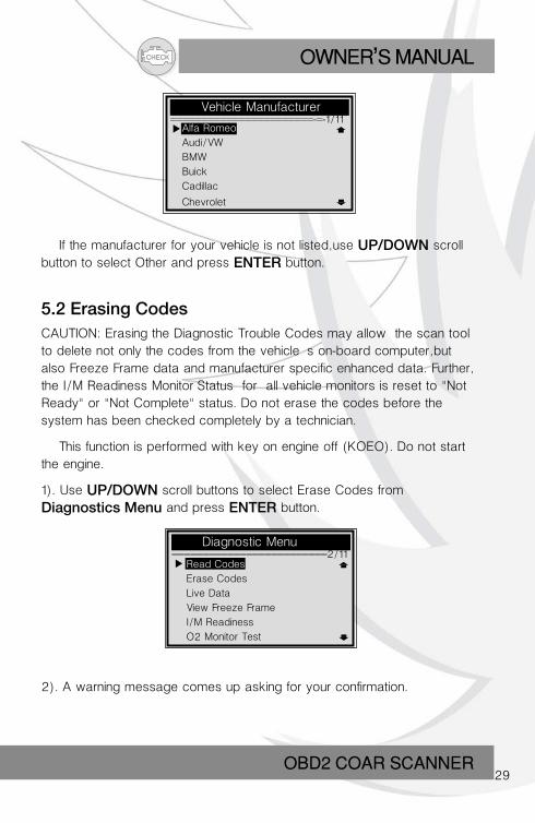
3). View DTCs and their definitions on screen.
Engine Coolant Temperature
Sensor 1 Circuit High
$09 1/5
P0118 Generic
The control module number, sequence of the DTCs, total number of codes detected and type of codes (Generic or Manufacturer specific) will be observed on the upper right hand corner of the display.
4). If more than one DTC is found, use UP/DOWN scroll button, as necessary, until all the codes have been shown up.
If retrieved DTCs contain any manufacturer specific or enhanced codes, a "Manufacturer specific codes are found! Press any key to select vehicle make!" message comes up prompting you to select vehicle manufacturer to view DTC definitions. Use UP/DOWN scroll button to select manufacturer and then press ENTER button to confirm.
Stored Codes
Pending Codes
CHECK OWNER S MANUAL,
OBD2 COAR SCANNER29
Vehicle Manufacturer =======================-=-1/11
Alfa Romeo
Audi/VW
BMW
Buick
Cadillac
Chevrolet
If the manufacturer for your vehicle is not listed, use UP/DOWN scroll button to select Other and press ENTER button.
Diagnostic Menu =========================2/11
5.2 Erasing CodesCAUTION: Erasing the Diagnostic Trouble Codes may allow the scan tool to delete not only the codes from the vehicle’s on-board computer, but also Freeze Frame data and manufacturer specific enhanced data. Further, the I/M Readiness Monitor Status for all vehicle monitors is reset to "Not Ready" or "Not Complete" status. Do not erase the codes before the system has been checked completely by a technician.
This function is performed with key on engine off (KOEO). Do not start the engine.
1). Use UP/DOWN scroll buttons to select Erase Codes from
Diagnostics Menu and press ENTER button.
2). A warning message comes up asking for your confirmation.
Read Codes
Erase Codes
Live Data
View Freeze Frame
I/M Readiness
O2 Monitor Test
CHECKOWNER S MANUAL,
OBD2 CAR SCANNER30
Erase Codes =============================
Erase Codes =============================
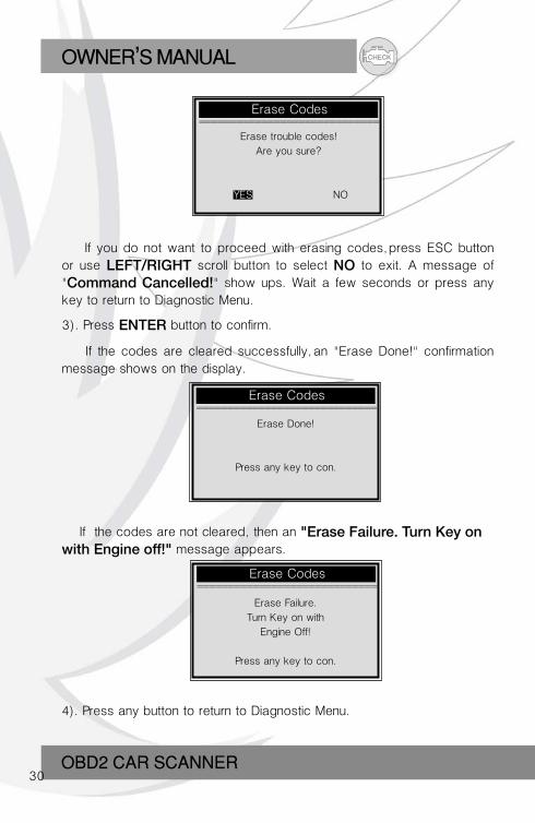
3). Press ENTER button to confirm.
If the codes are cleared successfully, an "Erase Done!" confirmation message shows on the display.
Erase Done!
Press any key to con.
Erase Failure.
Turn Key on with
Engine Off!
Press any key to con.
If the codes are not cleared, then an "Erase Failure. Turn Key on with Engine off!" message appears.
4). Press any button to return to Diagnostic Menu.
If you do not want to proceed with erasing codes, press ESC button or use LEFT/RIGHT scroll button to select NO to exit. A message of "Command Cancelled!" show ups. Wait a few seconds or press any key to return to Diagnostic Menu.
Erase Codes =============================
Erase trouble codes!
Are you sure?
YES NO
CHECK OWNER S MANUAL,
OBD2 COAR SCANNER31
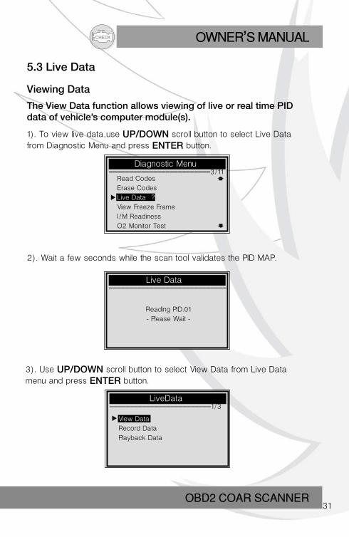
5.3 Live Data
Viewing Data
The View Data function allows viewing of live or real time PIDdata of vehicle’s computer module(s).
1). To view live data, use UP/DOWN scroll button to select Live Data from Diagnostic Menu and press ENTER button.
Diagnostic Menu =========================3/11
Live Data =============================
LiveData =========================1/3
2). Wait a few seconds while the scan tool validates the PID MAP.
Reading PID.01
- Please Wait -
3). Use UP/DOWN scroll button to select View Data from Live Data menu and press ENTER button.
Read Codes
Erase Codes
Live Data ?
View Freeze Frame
I/M Readiness
O2 Monitor Test
View Data
Record Data
Playback Data
CHECKOWNER S MANUAL,
OBD2 CAR SCANNER32
View Data =========================1/3
Live Data ===========================-
View Data =============================
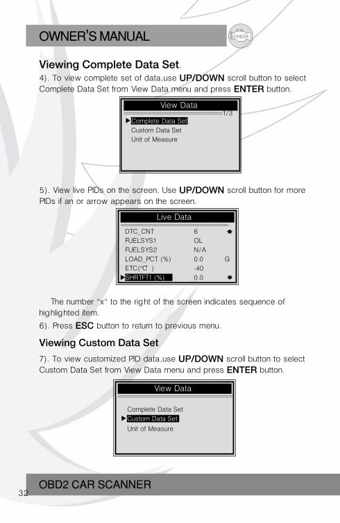
5). View live PIDs on the screen. Use UP/DOWN scroll button for more PIDs if an or arrow appears on the screen.
The number "x" to the right of the screen indicates sequence of highlighted item.
6). Press ESC button to return to previous menu.
Viewing Custom Data Set
7). To view customized PID data, use UP/DOWN scroll button to select Custom Data Set from View Data menu and press ENTER button.
Complete Data Set
Custom Data Set
Unit of Measure
DTC_CNT 6
FUELSYS1 OL
FUELSYS2 N/A
LOAD_PCT (%) 0.0 G
ETC( C ) -40
SHRTFT1 (%) 0.0
Complete Data Set
Custom Data Set
Unit of Measure
4). To view complete set of data, use UP/DOWN scroll button to select Complete Data Set from View Data menu and press ENTER button.
Viewing Complete Data Set.
CHECK OWNER S MANUAL,
OBD2 COAR SCANNER33
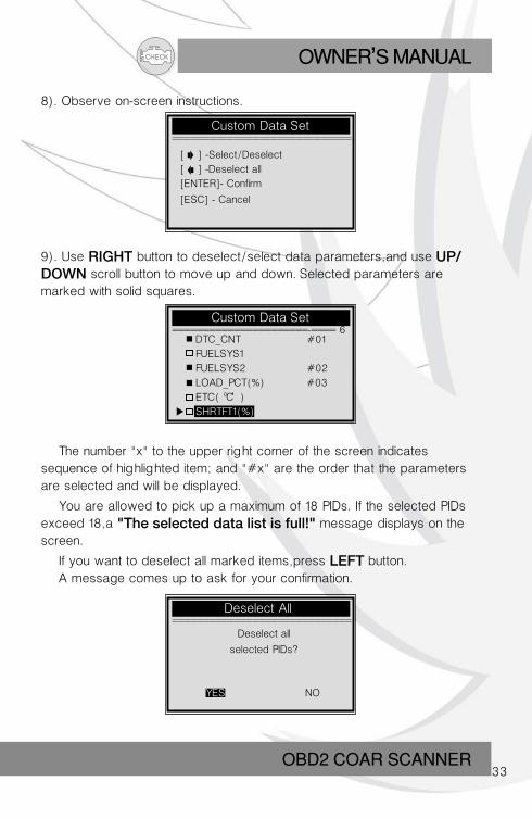
8). Observe on-screen instructions.
Custom Data Set =============================
[ ] -Select/Deselect
[ ] -Deselect all
[ENTER]- Confirm
[ESC] - Cancel
Custom Data Set ======================-==== 6
Deselect All =============================
9). Use RIGHT button to deselect/select data parameters, and use UP/DOWN scroll button to move up and down. Selected parameters are marked with solid squares.
The number "x" to the upper right corner of the screen indicates sequence of highlighted item; and "#x" are the order that the parameters are selected and will be displayed.
You are allowed to pick up a maximum of 18 PIDs. If the selected PIDs exceed 18, a "The selected data list is full!" message displays on the screen.
If you want to deselect all marked items, press LEFT button. A message comes up to ask for your confirmation.
Deselect all
selected PIDs?
YES NO
DTC_CNT #01
FUELSYS1
FUELSYS2 #02
LOAD_PCT(%) #03
ETC( C )
SHRTFT1(%)
CHECKOWNER S MANUAL,
OBD2 CAR SCANNER34
Live Data =============================
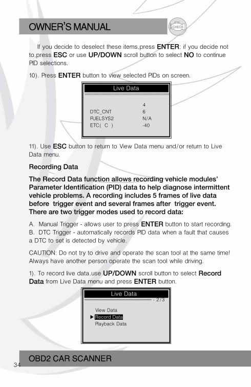
If you decide to deselect these items, press ENTER; if you decide not to, press ESC or use UP/DOWN scroll button to select NO to continue PID selections.
10). Press ENTER button to view selected PIDs on screen.
4
DTC_CNT 6
FUELSYS2 N/A
ETC( C ) -40
11). Use ESC button to return to View Data menu and/or return to Live Data menu.
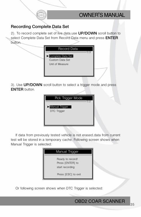
Recording Data
The Record Data function allows recording vehicle modules’ Parameter Identification (PID) data to help diagnose intermittent vehicle problems. A recording includes 5 frames of live data before trigger event and several frames after trigger event.There are two trigger modes used to record data:
A. Manual Trigger - allows user to press ENTER button to start recording.B. DTC Trigger - automatically records PID data when a fault that causes a DTC to set is detected by vehicle.
CAUTION: Do not try to drive and operate the scan tool at the same time! Always have another person operate the scan tool while driving.
1). To record live data, use UP/DOWN scroll button to select Record Data from Live Data menu and press ENTER button.
Live Data… ======================= - 2/3
View Data
Record Data
Playback Data
CHECK OWNER S MANUAL,
OBD2 COAR SCANNER35
Manual Trigger… =============================
Record Data… =========================1/3
Pick Trigger Mode… =========================1/2
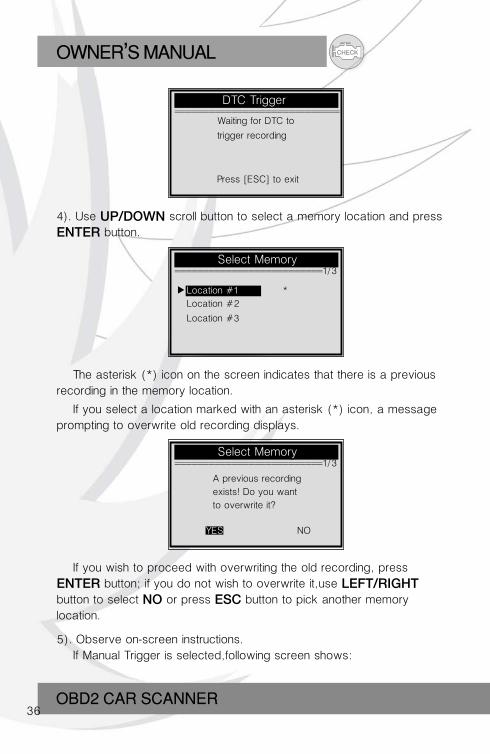
Recording Complete Data Set
2). To record complete set of live data, use UP/DOWN scroll button to select Complete Data Set from Record Data menu and press ENTER button.
3). Use UP/DOWN scroll button to select a trigger mode and press
ENTER button.
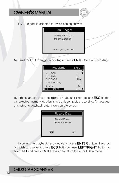
If data from previously tested vehicle is not erased, data from current test will be stored in a temporary cache. Following screen shows when Manual Trigger is selected:
Ready to record!
Press [ENTER] to
start recording…
Press [ESC] to exit
Or following screen shows when DTC Trigger is selected:
Complete Data Set
Custom Data Set
Unit of Measure
Manual Trigger
DTC Trigger
CHECKOWNER S MANUAL,
OBD2 CAR SCANNER36
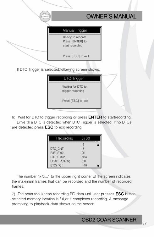
DTC Trigger… =============================
Select Memory… ==========================1/3
Select Memory… ==========================1/3
Waiting for DTC to
trigger recording…
Press [ESC] to exit
4). Use UP/DOWN scroll button to select a memory location and press
ENTER button.
The asterisk (*) icon on the screen indicates that there is a previous recording in the memory location.
If you select a location marked with an asterisk (*) icon, a message prompting to overwrite old recording displays.
A previous recording
exists! Do you want
to overwrite it?
YES NO
Location #1 *
Location #2
Location #3
If you wish to proceed with overwriting the old recording, press
ENTER button; if you do not wish to overwrite it, use LEFT/RIGHT button to select NO or press ESC button to pick another memory location.
5). Observe on-screen instructions. If Manual Trigger is selected, following screen shows:
CHECK OWNER S MANUAL,
OBD2 COAR SCANNER37
Manual Trigger… =============================
DTC Trigger… =============================
Recording… 5/60 ==========================-=-
Ready to record!
Press [ENTER] to
start recording…
Press [ESC] to exit
If DTC Trigger is selected, following screen shows:
Waiting for DTC to
trigger recording…
Press [ESC] to exit
6). Wait for DTC to trigger recording or press ENTER to startrecording. Drive till a DTC is detected when DTC Trigger is selected. If no DTCs are detected, press ESC to exit recording.
6
DTC_CNT 6
FUELSYS1 OL
FUELSYS2 N/A
LOAD_PCT(%) 0.0
ETC( C ) -40
The number "x/x..." to the upper right corner of the screen indicates the maximum frames that can be recorded and the number of recorded frames.
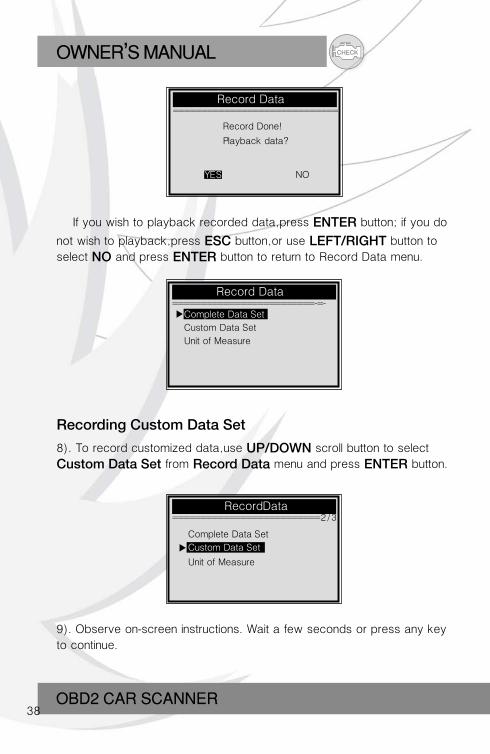
7). The scan tool keeps recording PID data until user presses ESC button, selected memory location is full,or it completes recording. A message prompting to playback data shows on the screen.
CHECKOWNER S MANUAL,
OBD2 CAR SCANNER38
Record Data… =============================
Record Data =========================-=-
Record Done!
Playback data?
YES NO
If you wish to playback recorded data, press ENTER button; if you do
not wish to playback, press ESC button, or use LEFT/RIGHT button to select NO and press ENTER button to return to Record Data menu.
Recording Custom Data Set
8). To record customized data, use UP/DOWN scroll button to select
Custom Data Set from Record Data menu and press ENTER button.
Complete Data Set
Custom Data Set
Unit of Measure
RecordData ==========================2/3
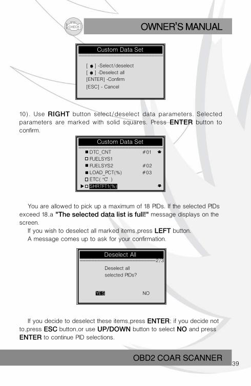
9). Observe on-screen instructions. Wait a few seconds or press any key to continue.
Complete Data Set
Custom Data Set
Unit of Measure
CHECK OWNER S MANUAL,
OBD2 COAR SCANNER39
Deselect All ==========================2/3
Custom Data Set =============================
[ ] -Select/deselect
[ ] -Deselect all
[ENTER] -Confirm
[ESC] - Cancel
10). Use RIGHT button select/deselect data parameters. Selected parameters are marked with solid squares. Press ENTER button to confirm.
Custom Data Set =============================
You are allowed to pick up a maximum of 18 PIDs. If the selected PIDs exceed 18, a "The selected data list is full!" message displays on the screen. If you wish to deselect all marked items, press LEFT button. A message comes up to ask for your confirmation.
Deselect all
selected PIDs?
YES NO
If you decide to deselect these items, press ENTER; if you decide not to, press ESC button, or use UP/DOWN button to select NO and press
ENTER to continue PID selections.
DTC_CNT #01
FUELSYS1
FUELSYS2 #02
LOAD_PCT(%) #03
ETC( C )
SHRTFT1(%)
CHECKOWNER S MANUAL,
OBD2 CAR SCANNER40
Custom Data Set =========================_=_5
Pick Trigger Mode =========================1/2
Manual Trigger =============================
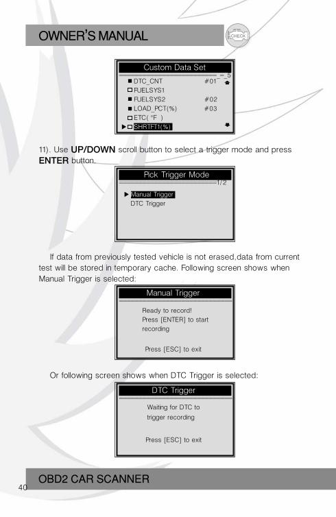
11). Use UP/DOWN scroll button to select a trigger mode and press
ENTER button.
If data from previously tested vehicle is not erased, data from current test will be stored in temporary cache. Following screen shows when Manual Trigger is selected:
Ready to record!
Press [ENTER] to start
recording……
Press [ESC] to exit
DTC_CNT #01
FUELSYS1
FUELSYS2 #02
LOAD_PCT(%) #03
ETC( F )
SHRTFT1(%)
Manual Trigger
DTC Trigger
Or following screen shows when DTC Trigger is selected:
DTC Trigger =============================
Waiting for DTC to
trigger recording…
Press [ESC] to exit
CHECK OWNER S MANUAL,
OBD2 COAR SCANNER41
Select Memory ==========================1/3
Select Memory =============================
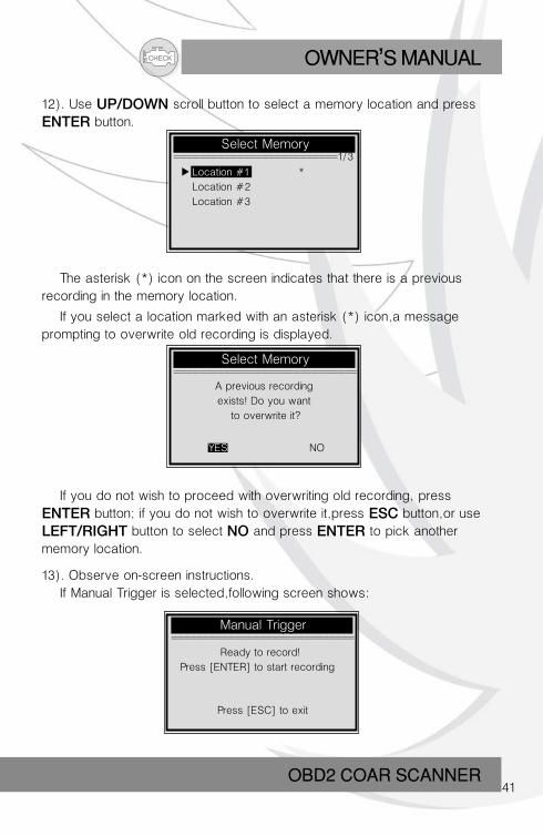
12). Use UP/DOWN scroll button to select a memory location and press
ENTER button.
The asterisk (*) icon on the screen indicates that there is a previous recording in the memory location.
If you select a location marked with an asterisk (*) icon, a message prompting to overwrite old recording is displayed.
A previous recording
exists! Do you want
to overwrite it?
YES NO
If you do not wish to proceed with overwriting old recording, press
ENTER button; if you do not wish to overwrite it, press ESC button, or use
LEFT/RIGHT button to select NO and press ENTER to pick another memory location.
13). Observe on-screen instructions. If Manual Trigger is selected, following screen shows:
Location #1 *
Location #2
Location #3
Manual Trigger =============================
Ready to record!
Press [ENTER] to start recording…
Press [ESC] to exit
CHECKOWNER S MANUAL,
OBD2 CAR SCANNER42
DTC Trigger =============================
Recording… 5/60 ==========================_=6
If DTC Trigger is selected, following screen shows:
Waiting for DTC to
trigger recording…
Press [ESC] to exit
14). Wait for DTC to trigger recording or press ENTER to start recording.
15). The scan tool keep recording PID data until user presses ESC button, the selected memory location is full, or it completes recording. A message prompting to playback data shows on the screen.
…………
DTC_CNT 6
FUELSYS1 OL
FUELSYS2 N/A
LOAD_PCT(%) 0.0
ETC( C) -40
SHRTFT1(%) 0.0
Record Data =============================
Record Done!
Playback data?
YES NO
If you wish to playback recorded data, press ENTER button; if you do not wish to playback, press ECS button, or use LEFT/RIGHT button to select NO and press ENTER button to return to Record Data menu.
CHECK OWNER S MANUAL,
OBD2 COAR SCANNER43
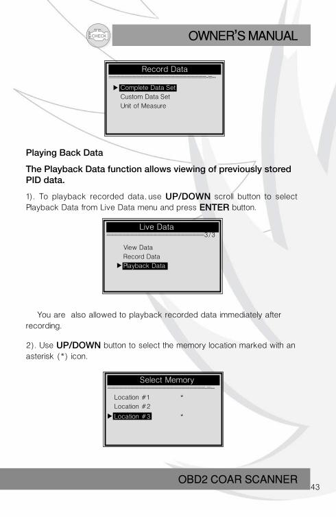
Record Data =========================-=--
Complete Data Set
Custom Data Set
Unit of Measure
Live Data =========================3/3
Playing Back Data
The Playback Data function allows viewing of previously storedPID data.
1). To playback recorded data, use UP/DOWN scroll button to select Playback Data from Live Data menu and press ENTER button.
You are also allowed to playback recorded data immediately after recording.
View Data
Record Data
Playback Data
Select Memory =========================-=--
2). Use UP/DOWN button to select the memory location marked with an asterisk (*) icon.
Location #1 *
Location #2
Location #3 *
CHECKOWNER S MANUAL,
OBD2 CAR SCANNER44
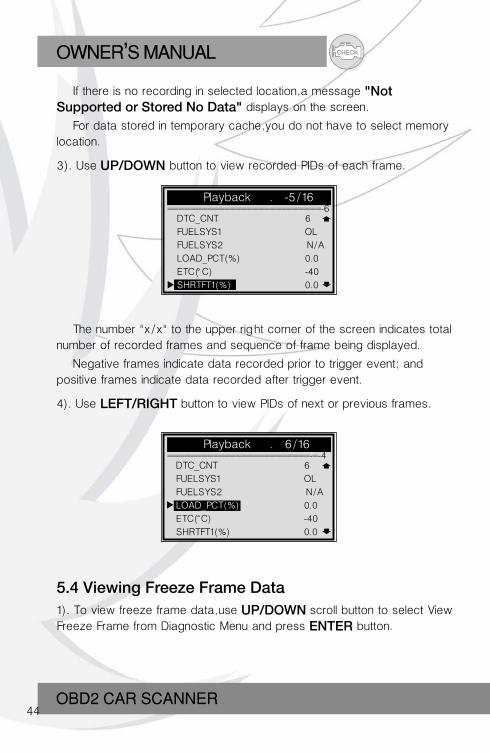
If there is no recording in selected location, a message "Not Supported or Stored No Data" displays on the screen.
For data stored in temporary cache, you do not have to select memory location.
3). Use UP/DOWN button to view recorded PIDs of each frame.
Playback …. -5/16 ===========================-6
Playback …. 6/16 =========================-=-4
The number "x/x" to the upper right corner of the screen indicates total number of recorded frames and sequence of frame being displayed.
Negative frames indicate data recorded prior to trigger event; and positive frames indicate data recorded after trigger event.
4). Use LEFT/RIGHT button to view PIDs of next or previous frames.
…………
DTC_CNT 6
FUELSYS1 OL
FUELSYS2 N/A
LOAD_PCT(%) 0.0
ETC( C) -40
SHRTFT1(%) 0.0
…………
DTC_CNT 6
FUELSYS1 OL
FUELSYS2 N/A
LOAD_PCT(%) 0.0
ETC( C) -40
SHRTFT1(%) 0.0
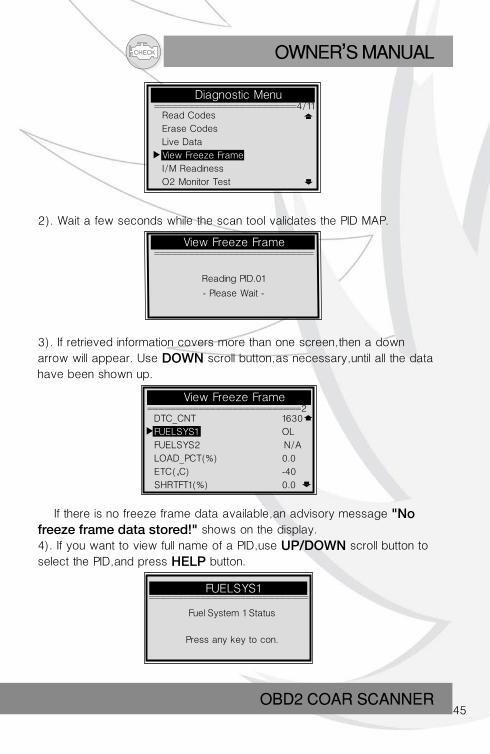
5.4 Viewing Freeze Frame Data1). To view freeze frame data, use UP/DOWN scroll button to select View Freeze Frame from Diagnostic Menu and press ENTER button.
CHECK OWNER S MANUAL,
OBD2 COAR SCANNER45
Diagnostic Menu =========================4/11
2). Wait a few seconds while the scan tool validates the PID MAP.
Read Codes
Erase Codes
Live Data
View Freeze Frame
I/M Readiness
O2 Monitor Test
View Freeze Frame ============================
Reading PID.01
- Please Wait -
3). If retrieved information covers more than one screen, then a down arrow will appear. Use DOWN scroll button, as necessary, until all the data have been shown up.
View Freeze Frame ===========================2
If there is no freeze frame data available, an advisory message "No freeze frame data stored!" shows on the display.4). If you want to view full name of a PID, use UP/DOWN scroll button to select the PID, and press HELP button.
…………
DTC_CNT 1630
FUELSYS1 OL
FUELSYS2 N/A
LOAD_PCT(%) 0.0
ETC( C) -40
SHRTFT1(%) 0.0
FUELSYS1
Fuel System 1 Status
Press any key to con.
============================
CHECKOWNER S MANUAL,
OBD2 CAR SCANNER46
5). Wait a few seconds or press any button to return to previous screen.
5.5 Retrieving I/M Readiness Status
I/M Readiness function is used to check the operations of the Emission System on OBD2 compliant vehicles. It is an excellent function to use prior to having a vehicle inspected for compliance to a state emissions program.
Some latest vehicle models may support two types of I/M Readiness
tests:
A. Since DTCs Cleared - indicates status of the monitors since theDTCs are erased.
B. This Drive Cycle - indicates status of monitors since the beginning of the current drive cycle.
An I/M Readiness Status result of NO does not necessarily indicate that the vehicle being tested will fail the state I/M inspection. For some states, one or more such monitors may be allowed to be "Not Ready" to pass the emissions inspection.
OK -- Indicates that a particular monitor being checked has completed its diagnostic testing. INC -- Indicates that a particular monitor being checked has not completed its diagnostic testing. N/A -- The monitor is not supported on that vehicle.
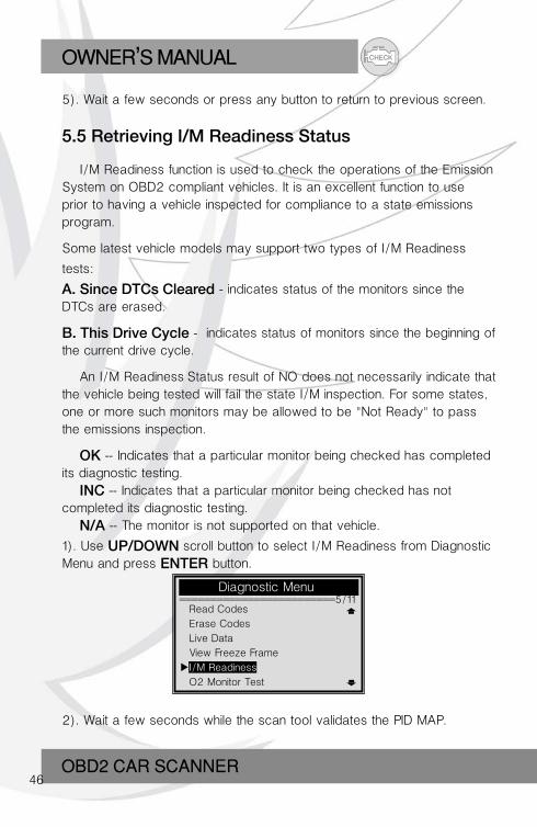
1). Use UP/DOWN scroll button to select I/M Readiness from Diagnostic Menu and press ENTER button.
Diagnostic Menu =========================5/11
2). Wait a few seconds while the scan tool validates the PID MAP.
Read Codes
Erase Codes
Live Data
View Freeze Frame
I/M Readiness
O2 Monitor Test
CHECK OWNER S MANUAL,
OBD2 COAR SCANNER47
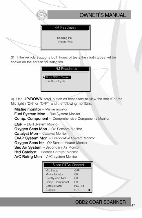
/M Readiness ============================
I/M Readiness ============================
Reading PID…
- Please Wait -
3). If the vehicle supports both types of tests, then both types will be shown on the screen for selection.
4). Use UP/DOWN scroll button, as necessary, to view the status of the MIL light ("ON" or "OFF") and the following monitors:
Misfire monitor -- Misfire monitor Fuel System Mon -- Fuel System Monitor Comp. Component -- Comprehensive Components Monitor
EGR -- EGR System Monitor Oxygen Sens Mon -- O2 Sensors Monitor Catalyst Mon -- Catalyst Monitor EVAP System Mon -- Evaporative System Monitor Oxygen Sens htr --O2 Sensor Heater Monitor Sec Air System -- Secondary Air Monitor Htd Catalyst -- Heated Catalyst Monitor A/C Refrig Mon -- A/C system Monitor
Since DTCs Cleared
This Drive Cycle
Since DTCs Cleared =============================
MIL Status OFF
Misfire Monitor OK
Fuel System Mon OK
Comp. Component OK
Catalyst Mon INC Htd
Catalyst N/A
CHECKOWNER S MANUAL,
OBD2 CAR SCANNER48
This Drive Cycle =============================
MIL Status OFF
Misfire Monitor OK
Fuel System Mon N/A
Comp. Component OK
Catalyst Mon INC
Htd Catalyst N/A
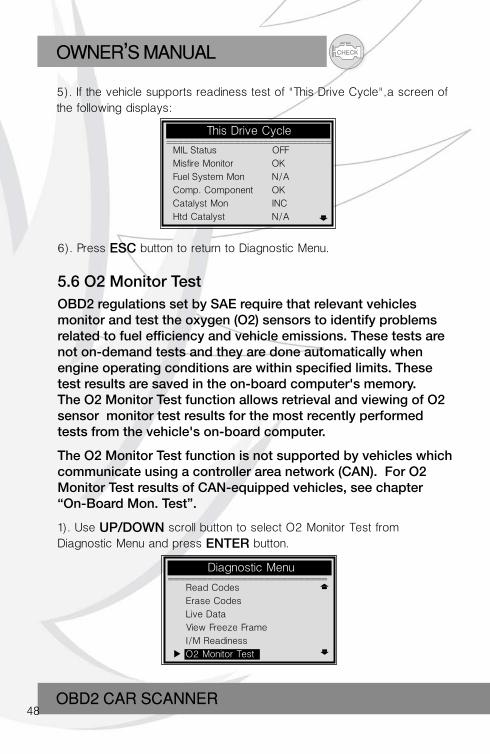
5). If the vehicle supports readiness test of "This Drive Cycle", a screen of the following displays:
6). Press ESC button to return to Diagnostic Menu.
5.6 O2 Monitor TestOBD2 regulations set by SAE require that relevant vehicles monitor and test the oxygen (O2) sensors to identify problems related to fuel efficiency and vehicle emissions. These tests are not on-demand tests and they are done automatically when engine operating conditions are within specified limits. These test results are saved in the on-board computer's memory.The O2 Monitor Test function allows retrieval and viewing of O2sensor monitor test results for the most recently performed tests from the vehicle's on-board computer.
The O2 Monitor Test function is not supported by vehicles which communicate using a controller area network (CAN). For O2Monitor Test results of CAN-equipped vehicles, see chapter“On-Board Mon. Test”.
1). Use UP/DOWN scroll button to select O2 Monitor Test from Diagnostic Menu and press ENTER button.
Diagnostic Menu ============================
Read Codes
Erase Codes
Live Data
View Freeze Frame
I/M Readiness
O2 Monitor Test
CHECK OWNER S MANUAL,
OBD2 COAR SCANNER49
O2 Monitor Test ======================-=:=2/2
O2 Monitor Test ============================
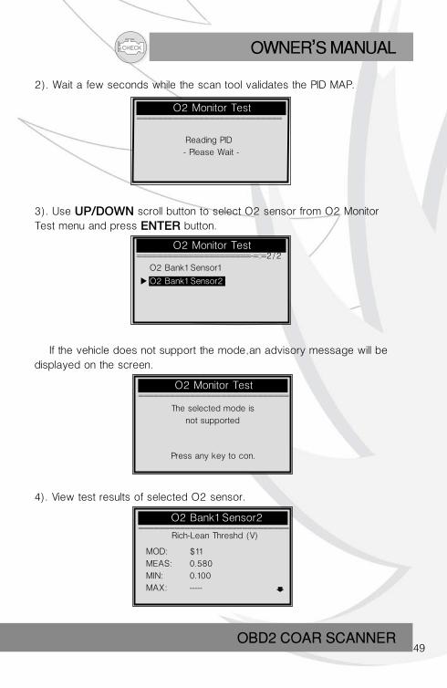
2). Wait a few seconds while the scan tool validates the PID MAP.
Reading PID…
- Please Wait -
O2 Bank1 Sensor1
O2 Bank1 Sensor2
3). Use UP/DOWN scroll button to select O2 sensor from O2 Monitor Test menu and press ENTER button.
O2 Monitor Test =============================
O2 Bank1 Sensor2 =============================
If the vehicle does not support the mode, an advisory message will be displayed on the screen.
The selected mode is
not supported
Press any key to con.
4). View test results of selected O2 sensor.
Rich-Lean Threshd (V)
MOD: $11
MEAS: 0.580
MIN: 0.100
MAX: -----
CHECKOWNER S MANUAL,
OBD2 CAR SCANNER50
5). Use UP/DOWN scroll button to view more screens of data if an or icon displays.
6) Press ESC button to return to the previous menus.
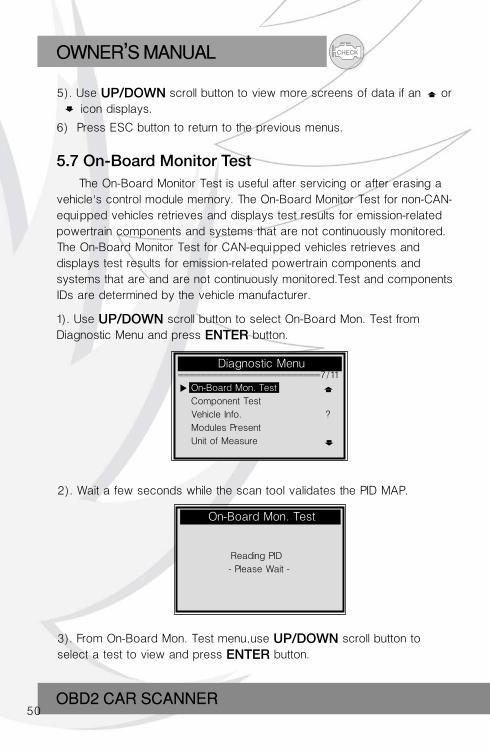
5.7 On-Board Monitor Test The On-Board Monitor Test is useful after servicing or after erasing a vehicle's control module memory. The On-Board Monitor Test for non-CAN-equipped vehicles retrieves and displays test results for emission-related powertrain components and systems that are not continuously monitored. The On-Board Monitor Test for CAN-equipped vehicles retrieves and displays test results for emission-related powertrain components and systems that are and are not continuously monitored.Test and components IDs are determined by the vehicle manufacturer.
1). Use UP/DOWN scroll button to select On-Board Mon. Test from Diagnostic Menu and press ENTER button.
On-Board Mon. Test
Diagnostic Menu =========================7/11
2). Wait a few seconds while the scan tool validates the PID MAP.
Reading PID…
- Please Wait -
3). From On-Board Mon. Test menu, use UP/DOWN scroll button to select a test to view and press ENTER button.
On-Board Mon. Test
Component Test
Vehicle Info. ?
Modules Present
Unit of Measure
CHECK OWNER S MANUAL,
OBD2 COAR SCANNER51
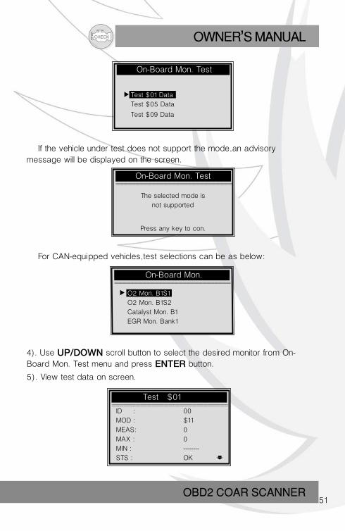
On-Board Mon. Test
Test $01 Data
Test $05 Data
Test $09 Data
On-Board Mon. Test =============================
If the vehicle under test does not support the mode, an advisory message will be displayed on the screen.
The selected mode is
not supported
Press any key to con.
On-Board Mon. =============================
Test $01 =============================
For CAN-equipped vehicles, test selections can be as below:
4). Use UP/DOWN scroll button to select the desired monitor from On-Board Mon. Test menu and press ENTER button.
5). View test data on screen.
ID : 00
MOD : $11
MEAS: 0
MAX : 0
MIN : --------
STS : OK
O2 Mon. B1S1
O2 Mon. B1S2
Catalyst Mon. B1
EGR Mon. Bank1
CHECKOWNER S MANUAL,
OBD2 CAR SCANNER52
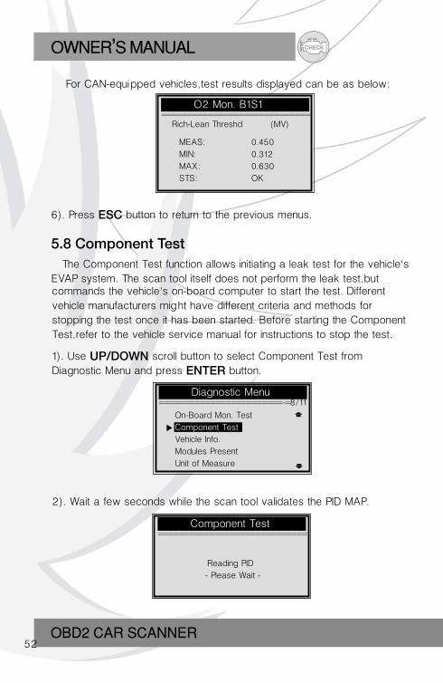
For CAN-equipped vehicles, test results displayed can be as below:
O2 Mon. B1S1 =============================
Rich-Lean Threshd (MV)
MEAS: 0.450
MIN: 0.312
MAX: 0.630
STS: OK
6). Press ESC button to return to the previous menus.
5.8 Component Test The Component Test function allows initiating a leak test for the vehicle's EVAP system. The scan tool itself does not perform the leak test, but
Diagnostic Menu ========================-=8/11
commands the vehicle's on-board computer to start the test. Different vehicle manufacturers might have different criteria and methods for stopping the test once it has been started. Before starting the Component Test, refer to the vehicle service manual for instructions to stop the test.
1). Use UP/DOWN scroll button to select Component Test from Diagnostic Menu and press ENTER button.
2). Wait a few seconds while the scan tool validates the PID MAP.
On-Board Mon. Test
Component Test
Vehicle Info.
Modules Present
Unit of Measure
Component Test =============================
Reading PID…
- Please Wait -
CHECK OWNER S MANUAL,
OBD2 COAR SCANNER53
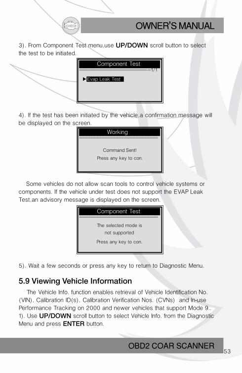
3). From Component Test menu, use UP/DOWN scroll button to select the test to be initiated.
Component Test ========================-=1/1
4). If the test has been initiated by the vehicle, a confirmation message will be displayed on the screen.
Evap Leak Test
Working ============================
Component Test ============================
Command Sent!
Press any key to con.
Some vehicles do not allow scan tools to control vehicle systems or components. If the vehicle under test does not support the EVAP Leak Test, an advisory message is displayed on the screen.
The selected mode is
not supported
Press any key to con.
5). Wait a few seconds or press any key to return to Diagnostic Menu.
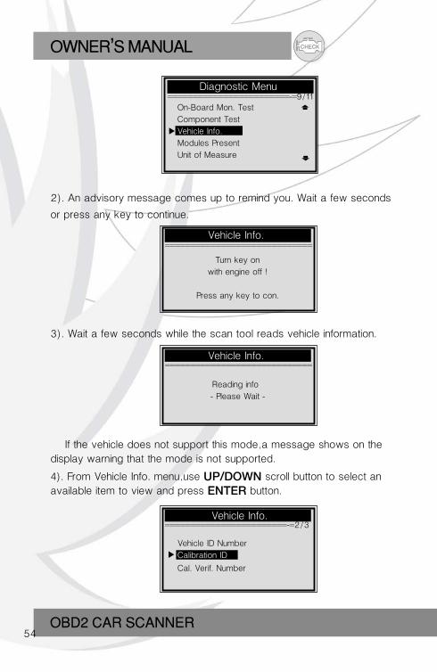
5.9 Viewing Vehicle Information The Vehicle Info. function enables retrieval of Vehicle Identification No. (VIN), Calibration ID(s), Calibration Verification Nos. (CVNs) and In-use Performance Tracking on 2000 and newer vehicles that support Mode 9..1). Use UP/DOWN scroll button to select Vehicle Info. from the Diagnostic Menu and press ENTER button.
CHECKOWNER S MANUAL,
OBD2 CAR SCANNER54
Diagnostic Menu ========================-=9/11
On-Board Mon. Test
Component Test
Vehicle Info.
Modules Present
Unit of Measure
Vehicle Info. ========================-=2/3
Vehicle Info. =============================
Vehicle Info. =============================
2). An advisory message comes up to remind you. Wait a few seconds
or press any key to continue.
Turn key on
with engine off !
Press any key to con.
3). Wait a few seconds while the scan tool reads vehicle information.
Reading info…
- Please Wait -
Vehicle ID Number
Calibration ID
Cal. Verif. Number
If the vehicle does not support this mode, a message shows on the display warning that the mode is not supported.
4). From Vehicle Info. menu, use UP/DOWN scroll button to select an available item to view and press ENTER button.
CHECK OWNER S MANUAL,
OBD2 COAR SCANNER55
Calibration ID =============================
Diagnostic Menu =======================-=10/11
Cal ID1:
30668343
Cal ID2:
08644359
6). Press ESC button to return previous menu
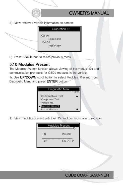
5.10 Modules PresentThe Modules Present function allows viewing of the module IDs and communication protocols for OBD2 modules in the vehicle.
1). Use UP/DOWN scroll button to select Modules Present fromDiagnostic Menu and press ENTER button.
On-Board Mon. Test
Component Test
Vehicle Info.
Modules Present
Unit of Measure
2). View modules present with their IDs and communication protocols.
Modules Present =======================-=10/11
ID Protocol
_________________________
$11 ISO 9141-2
5). View retrieved vehicle information on screen.
CHECKOWNER S MANUAL,
OBD2 CAR SCANNER56
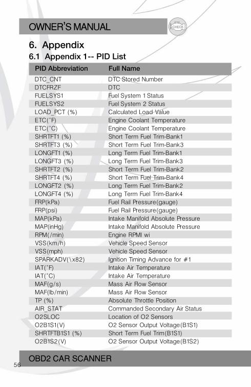
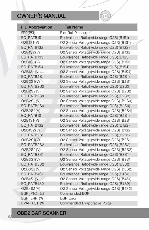
6. Appendix6.1 Appendix 1-- PID List
DTC_CNT DTC Stored NumberDTCFRZF DTCFUELSYS1 Fuel System 1 StatusFUELSYS2 Fuel System 2 StatusLOAD_PCT (%) Calculated Load ValueETC(°F) Engine Coolant TemperatureETC(°C) Engine Coolant TemperatureSHRTFT1 (%) Short Term Fuel Trim-Bank1SHRTFT3 (%) Short Term Fuel Trim-Bank3LONGFT1 (%) Long Term Fuel Trim-Bank1LONGFT3 (%) Long Term Fuel Trim-Bank3SHRTFT2 (%) Short Term Fuel Trim-Bank2SHRTFT4 (%) Short Term Fuel Trim-Bank4LONGFT2 (%) Long Term Fuel Trim-Bank2LONGFT4 (%) Long Term Fuel Trim-Bank4FRP(kPa) Fuel Rail Pressure(gauge)FRP(psi) Fuel Rail Pressure(gauge)MAP(kPa) Intake Manifold Absolute PressureMAP(inHg) Intake Manifold Absolute PressureRPM(/min) Engine RPMI wiVSS(km/h) Vehicle Speed SensorVSS(mph) Vehicle Speed SensorSPARKADV(\x82) Ignition Timing Advance for #1IAT(°F) Intake Air TemperatureIAT(°C) Intake Air TemperatureMAF(g/s) Mass Air Flow SensorMAF(lb/min) Mass Air Flow SensorTP (%) Absolute Throttle PositionAIR_STAT Commanded Secondary Air StatusO2SLOC Location of O2 SensorsO2B1S1(V) O2 Sensor Output Voltage(B1S1)SHRTFTB1S1 (%) Short Term Fuel Trim(B1S1)O2B1S2(V) O2 Sensor Output Voltage(B1S2)
PID Abbreviation Full Name
CHECK OWNER S MANUAL,
OBD2 COAR SCANNER57
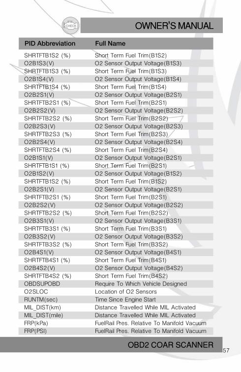
SHRTFTB1S2 (%) Short Term Fuel Trim(B1S2)O2B1S3(V) O2 Sensor Output Voltage(B1S3)SHRTFTB1S3 (%) Short Term Fuel Trim(B1S3)O2B1S4(V) O2 Sensor Output Voltage(B1S4)SHRTFTB1S4 (%) Short Term Fuel Trim(B1S4)O2B2S1(V) O2 Sensor Output Voltage(B2S1)SHRTFTB2S1 (%) Short Term Fuel Trim(B2S1)O2B2S2(V) O2 Sensor Output Voltage(B2S2)SHRTFTB2S2 (%) Short Term Fuel Trim(B2S2)O2B2S3(V) O2 Sensor Output Voltage(B2S3)SHRTFTB2S3 (%) Short Term Fuel Trim(B2S3)O2B2S4(V) O2 Sensor Output Voltage(B2S4)SHRTFTB2S4 (%) Short Term Fuel Trim(B2S4)O2B1S1(V) O2 Sensor Output Voltage(B2S1)SHRTFTB1S1 (%) Short Term Fuel Trim(B2S1)O2B1S2(V) O2 Sensor Output Voltage(B1S2)SHRTFTB1S2 (%) Short Term Fuel Trim(B1S2)O2B2S1(V) O2 Sensor Output Voltage(B2S1)SHRTFTB2S1 (%) Short Term Fuel Trim(B2S1)O2B2S2(V) O2 Sensor Output Voltage(B2S2)SHRTFTB2S2 (%) Short Term Fuel Trim(B2S2)O2B3S1(V) O2 Sensor Output Voltage(B3S1)SHRTFTB3S1 (%) Short Term Fuel Trim(B3S1)O2B3S2(V) O2 Sensor Output Voltage(B3S2)SHRTFTB3S2 (%) Short Term Fuel Trim(B3S2)O2B4S1(V) O2 Sensor Output Voltage(B4S1)SHRTFTB4S1 (%) Short Term Fuel Trim(B4S1)O2B4S2(V) O2 Sensor Output Voltage(B4S2)SHRTFTB4S2 (%) Short Term Fuel Trim(B4S2)OBDSUP OBD Require To Which Vehicle DesignedO2SLOC Location of O2 SensorsRUNTM(sec) Time Since Engine StartMIL_DIST(km) Distance Travelled While MIL ActivatedMIL_DIST(mile) Distance Travelled While MIL ActivatedFRP(kPa) FuelRail Pres. Relative To Manifold VacuumFRP(PSI) FuelRail Pres. Relative To Manifold Vacuum
PID Abbreviation Full Name
CHECKOWNER S MANUAL,
OBD2 CAR SCANNER58
FRP(kPa) Fuel Rail PressureFRP(PSI) Fuel Rail PressureEQ_RATB1S1 Equivalence Ratio(wide range O2S)(B1S1)O2B1S1(V) O2 Sensor Voltage(wide range O2S)(B1S1)EQ_RATB1S2 Equivalence Ratio(wide range O2S)(B1S2)O2B1S2(V) O2 Sensor Voltage(wide range O2S)(B1S2)EQ_RATB1S3 Equivalence Ratio(wide range O2S)(B1S3)O2B1S3(V) O2 Sensor Voltage(wide range O2S)(B1S3)EQ_RATB1S4 Equivalence Ratio(wide range O2S)(B1S4)O2B1S4(V) O2 Sensor Voltage(wide range O2S)(B1S4)EQ_RATB2S1 Equivalence Ratio(wide range O2S)(B2S1)O2B2S1(V) O2 Sensor Voltage(wide range O2S)(B2S1)EQ_RATB2S2 Equivalence Ratio(wide range O2S)(B2S2)O2B2S2(V) O2 Sensor Voltage(wide range O2S)(B2S2)EQ_RATB2S3 Equivalence Ratio(wide range O2S)(B2S3)O2B2S3(V) O2 Sensor Voltage(wide range O2S)(B2S3)EQ_RATB2S4 Equivalence Ratio(wide range O2S)(B2S4)O2B2S4(V) O2 Sensor Voltage(wide range O2S)(B2S4)EQ_RATB1S1 Equivalence Ratio(wide range O2S)(B2S1)O2B1S1(V) O2 Sensor Voltage(wide range O2S)(B2S1)EQ_RATB1S2 Equivalence Ratio(wide range O2S)(B1S2)O2B1S2(V) O2 Sensor Voltage(wide range O2S)(B1S2)EQ_RATB2S1 Equivalence Ratio(wide range O2S)(B2S1)O2B2S1(V) O2 Sensor Voltage(wide range O2S)(B2S1)EQ_RATB2S2 Equivalence Ratio(wide range O2S)(B2S2)O2B2S2(V) O2 Sensor Voltage(wide range O2S)(B2S2)EQ_RATB3S1 Equivalence Ratio(wide range O2S)(B3S1)O2B3S1(V) O2 Sensor Voltage(wide range O2S)(B3S1)EQ_RATB3S2 Equivalence Ratio(wide range O2S)(B3S2)O2B3S2(V) O2 Sensor Voltage(wide range O2S)(B3S2)EQ_RATB4S1 Equivalence Ratio(wide range O2S)(B4S1)O2B4S1(V) O2 Sensor Voltage(wide range O2S)(B4S1)EQ_RATB4S2 Equivalence Ratio(wide range O2S)(B4S2)O2B4S2(V) O2 Sensor Voltage(wide range O2S)(B4S2)EGR_PTC (%) Commanded EGREGR_ERR (%) EGR ErrorEVAP_PCT (%) Commanded Evaporative Purge
PID Abbreviation Full Name
CHECK OWNER S MANUAL,
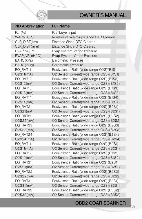
OBD2 COAR SCANNER59
FLI (%) Fuel Level InputWARM_UPS Number of Warm-ups Since DTC ClearedCLR_DIST(km) Distance Since DTC ClearedCLR_DIST(mile) Distance Since DTC ClearedEVAP_VP(Pa) Evap System Vapor PressureEVAP_VP(inH2O) Evap System Vapor PressureBARO(kPa) Barometric PressureBARO(inHg) Barometric PressureEQ_RAT11 Equivalence Ratio(wide range O2S)(B1S1)O2S11(mA) O2 Sensor Current(wide range O2S)(B1S1)EQ_RAT12 Equivalence Ratio(wide range O2S)(B1S2)O2S12(mA) O2 Sensor Current(wide range O2S)(B1S2)EQ_RAT13 Equivalence Ratio(wide range O2S)(B1S3)O2S13(mA) O2 Sensor Current(wide range O2S)(B1S3)EQ_RAT14 Equivalence Ratio(wide range O2S)(B1S4)O2S14(mA) O2 Sensor Current(wide range O2S)(B1S4)EQ_RAT21 Equivalence Ratio(wide range O2S)(B2S1)O2S21(mA) O2 Sensor Current(wide range O2S)(B2S1)EQ_RAT22 Equivalence Ratio(wide range O2S)(B2S2)O2S22(mA) O2 Sensor Current(wide range O2S)(B2S2)EQ_RAT23 Equivalence Ratio(wide range O2S)(B2S3)O2S23(mA) O2 Sensor Current(wide range O2S)(B2S3)EQ_RAT24 Equivalence Ratio(wide range O2S)(B2S4)O2S24(mA) O2 Sensor Current(wide range O2S)(B2S4)EQ_RAT11 Equivalence Ratio(wide range O2S)(B2S1)O2S11(mA) O2 Sensor Current(wide range O2S)(B2S1)EQ_RAT12 Equivalence Ratio(wide range O2S)(B1S2)O2S12(mA) O2 Sensor Current(wide range O2S)(B1S2)EQ_RAT21 Equivalence Ratio(wide range O2S)(B2S1)O2S21(mA) O2 Sensor Current(wide range O2S)(B2S1)EQ_RAT22 Equivalence Ratio(wide range O2S)(B2S2)O2S22(mA) O2 Sensor Current(wide range O2S)(B2S2)EQ_RAT31 Equivalence Ratio(wide range O2S)(B3S1)O2S31(mA) O2 Sensor Current(wide range O2S)(B3S1)EQ_RAT32 Equivalence Ratio(wide range O2S)(B3S2)O2S32(mA) O2 Sensor Current(wide range O2S)(B3S2)
PID Abbreviation Full Name
CHECKOWNER S MANUAL,
OBD2 CAR SCANNER60
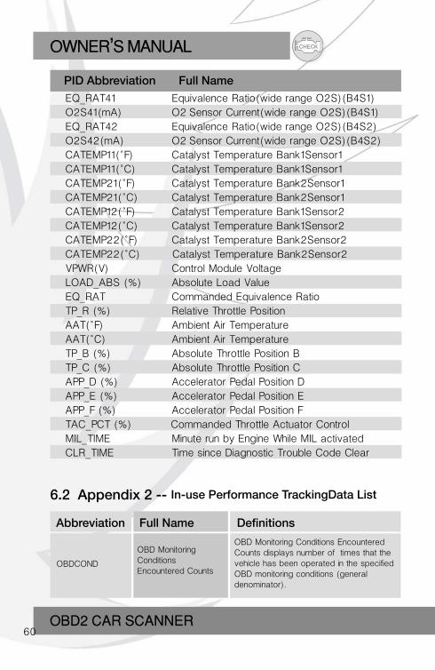
EQ_RAT41 Equivalence Ratio(wide range O2S)(B4S1)O2S41(mA) O2 Sensor Current(wide range O2S)(B4S1)EQ_RAT42 Equivalence Ratio(wide range O2S)(B4S2)O2S42(mA) O2 Sensor Current(wide range O2S)(B4S2)CATEMP11(°F) Catalyst Temperature Bank1Sensor1CATEMP11(°C) Catalyst Temperature Bank1Sensor1CATEMP21(°F) Catalyst Temperature Bank2Sensor1CATEMP21(°C) Catalyst Temperature Bank2Sensor1CATEMP12(°F) Catalyst Temperature Bank1Sensor2CATEMP12(°C) Catalyst Temperature Bank1Sensor2CATEMP22(°F) Catalyst Temperature Bank2Sensor2CATEMP22(°C) Catalyst Temperature Bank2Sensor2VPWR(V) Control Module VoltageLOAD_ABS (%) Absolute Load ValueEQ_RAT Commanded Equivalence RatioTP_R (%) Relative Throttle PositionAAT(°F) Ambient Air TemperatureAAT(°C) Ambient Air TemperatureTP_B (%) Absolute Throttle Position BTP_C (%) Absolute Throttle Position CAPP_D (%) Accelerator Pedal Position DAPP_E (%) Accelerator Pedal Position EAPP_F (%) Accelerator Pedal Position FTAC_PCT (%) Commanded Throttle Actuator ControlMIL_TIME Minute run by Engine While MIL activatedCLR_TIME Time since Diagnostic Trouble Code Clear
PID Abbreviation Full Name
OBDCOND
OBD MonitoringConditionsEncountered Counts
OBD Monitoring Conditions Encountered Counts displays number of times that the vehicle has been operated in the specified OBD monitoring conditions (general denominator).
Abbreviation Full Name Definitions
6.2 Appendix 2 -- In-use Performance TrackingData List
CHECK OWNER S MANUAL,
OBD2 COAR SCANNER61
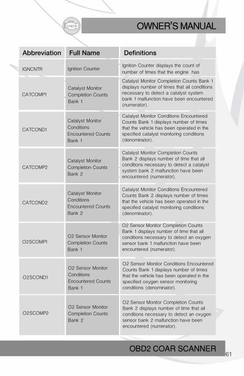
Abbreviation Full Name Definitions
O2SCOND1
O2 Sensor Monitor
Conditions
Encountered Counts
Bank 1
O2 Sensor Monitor Conditions Encountered Counts Bank 1 displays number of times that the vehicle has been operated in the specified oxygen sensor monitoring conditions (denominator).
IGNCNTR
CATCOMP1
CATCOND1
CATCOMP2
CATCOND2
Ignition Counter
Catalyst Monitor
Completion Counts
Bank 1
Catalyst Monitor
Conditions
Encountered Counts
Bank 1
Catalyst Monitor
Completion Counts
Bank 2
Catalyst Monitor
Conditions
Encountered Counts
Bank 2
Ignition Counter displays the count of
number of times that the engine has
Catalyst Monitor Completion Counts Bank 1 displays number of times that all conditions necessary to detect a catalyst system bank 1 malfunction have been encountered (numerator).
Catalyst Monitor Conditions Encountered Counts Bank 1 displays number of times that the vehicle has been operated in the specified catalyst monitoring conditions (denominator).
Catalyst Monitor Completion Counts Bank 2 displays number of time that all conditions necessary to detect a catalyst system bank 2 malfunction have been encountered (numerator).
Catalyst Monitor Conditions Encountered Counts Bank 2 displays number of times that the vehicle has been operated in the specified catalyst monitoring conditions (denominator).
O2SCOMP1O2 Sensor Monitor
Completion Counts
Bank 1
O2 Sensor Monitor Completion Counts Bank 1 displays number of time that all conditions necessary to detect an oxygen sensor bank 1 malfunction have been encountered (numerator).
O2SCOMP2O2 Sensor Monitor
Completion Counts
Bank 2
O2 Sensor Monitor Completion Counts Bank 2 displays number of time that all conditions necessary to detect an oxygen sensor bank 2 malfunction have been encountered (numerator).
CHECKOWNER S MANUAL,
OBD2 CAR SCANNER62
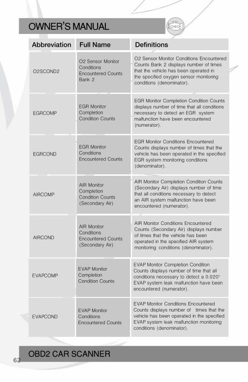
O2SCOND2
EGRCOMP
O2 Sensor MonitorConditionsEncountered CountsBank 2
EGR MonitorCompletionCondition Counts
O2 Sensor Monitor Conditions Encountered Counts Bank 2 displays number of times that the vehicle has been operated in the specified oxygen sensor monitoring conditions (denominator).
EGR Monitor Completion Condition Counts displays number of time that all conditions necessary to detect an EGR system malfunction have been encountered (numerator).
Abbreviation Full Name Definitions
EGRCOND
AIRCOMP
AIRCOND
EGR MonitorConditionsEncountered Counts
AIR MonitorCompletionCondition Counts(Secondary Air)
AIR MonitorConditionsEncountered Counts(Secondary Air)
EGR Monitor Conditions EncounteredCounts displays number of times that the vehicle has been operated in the specified EGR system monitoring conditions (denominator).
AIR Monitor Completion Condition Counts (Secondary Air) displays number of time that all conditions necessary to detect an AIR system malfunction have been encountered (numerator).
AIR Monitor Conditions EncounteredCounts (Secondary Air) displays number of times that the vehicle has been operated in the specified AIR system monitoring conditions (denominator).
EVAPCOMP
EVAPCOND
EVAP MonitorCompletionCondition Counts
EVAP MonitorConditionsEncountered Counts
EVAP Monitor Completion Condition Counts displays number of time that all conditions necessary to detect a 0.020" EVAP system leak malfunction have been encountered (numerator).
EVAP Monitor Conditions Encountered Counts displays number of times that the vehicle has been operated in the specifiedEVAP system leak malfunction monitoring conditions (denominator).
CHECK OWNER S MANUAL,
OBD2 COAR SCANNER63
7. Warranty and Service
7.1 Limited One Year Warranty We warrant to the customers that this product will be free from all defects in materials and workmanship for a period of one (1) year from the date of the original purchase, subject to the following terms and conditions:
1). The sole responsibility of us under the Warranty is limited to either the repair or, at the option of us, replacement of the scan tool at no charge with Proof of Purchase. The sales receipt may be used for this purpose.
2). This warranty does not apply to damages caused by improper use, accident, flood, lightning, or if the product was altered or repaired by anyone other than the Manufacturer’s Service Center.
3). We shall not be liable for any incidental or consequential damages arising from the use, misuse, or mounting of the scan tool. Some states do not allow limitations on how long an implied warranty lasts, so the above limitations may not apply to you.
4). All information in this manual is based on the latest information available at the time of publication and no warranty can be made for its accuracy or completeness. We reserves the right to make changes at any time without notice.
7.2 Service Procedures If you have any questions, please contact your local store, distributor or
visit our website.
If it becomes necessary to return the scan tool for repair, contact your local distributor for more information.