Embed Size (px)
Citation preview

1
OWNER’S OPERATION AND INSTALLATION MANUAL
Vent Free L.P.& NATURALGAS VENT-FREE STOVE
This appliance may be installed in an aftermarket*,permanently located manufactured (mobile) home,where not prohibited by local codes.This appliance is only for use with the type of gasindicated on the rating plate. This appliance is notconvertible for use with other gases.
* Aftermarket: Completion of sale, not for purpose of resale,from the manufacturer.
Consumer : Please retain these instruction forfuture use.
Do not store or use gasoline or other flammablevapors and liquids in the vicinity of this or anyother appliance.WHAT TO DO IF YOU SMELL GASl Do not try to light any appliance.l Do not touch any electrical switch; do not use any
phone in your building.l Immediately call your gas supplier from a neighbor’s
phone. Follow the gas supplier’s instructions.l If you cannot reach your gas supplier, call the
fire department.Installation and service must be performed bya qualified installer, service agency, or localgas supplier.
WATER VAPOR: A BY-PRODUCT OF UNVENTED ROOMHEATERSWater vapor is a by-product of gas combustion. Anunvented room heater produces approximately one(1) ounce (30)ml of water for every 1,000BTU’S (.3KW’S) OF gas input per hour, Refer to page 7.
Installer: Please leave these instructions with theconsumer.
TOLL-FREE NUMBER: 1-877-886-5989
Continental Appliance Inc./U.S. Office5 Musick 4600 Highlands Parkway S.E. Irvine Suite# D/ECA 92618 Smyrna GA 30080
Nanjing PRO-COM Electric Appliance Co., Ltd.#6 Chuangye Road, High New Tech. Zone,Great Bridge Road North, Nanjing, 210061, China.
SSU320RHN-GBSSU320RHN-BSSU320RHN-GSSU320RHN-S
SSU320RHL-GBSSU320RHL-BSSU320RHL-GSSU320RHL-S
PC-SL035A058-0505
WARNING: Improper installation,adjustment, alteration, service or main-tenance can cause injury or propertydamage. Refer to this manual for correct in-stallation and operational procedures. Forassistance or additional information con-sult a qualified installer, service agency, orlocal gas supplier.
WARNING: This is an unvented gas-fired heater. It uses air (oxygen) from theroom in which it is installed. Provisionsfor adequate combustion and ventilationair must be provided. Refer to Air ForCombustion and Ventilation section onpage 5 of this manual.
WARNING: If the information in thismanual is not followed exactly, a f i re or ex-p l o s i o n m a y r e s u l t causing propertydamage, personal injury, or loss of life.
2
Table of ContentsSafety Information-----------------------------------------------------------------------------------------2Product Features-------------------------------------------------------------------------------------------------4Local codes--------------------------------------------------------------------------------------------------------4Unpacking--------------------------------------- ---- ----------------------------------------------------------------4Air for Combustion & Ventilat ion------- ----- ----- ------ ----- ----- -- ---------------------------------------5Installation----------------------------------------------------------------------------------------------------------7Connecting To Gas Supply------------------------------------------------------------------------------------8Checking Gas Connections-----------------------------------------------------------------------------------9Log Placement---------------------------------------------------------------------------------------------------10Operating Heater-------------------------------------------------------------------------------------------------11Cleaning and Maintenance----------------------------------------------------------------------------------14Specification------------------------------------------------------------------------------------------------------16Troubleshooting---------------------------------- ----------------------------------------------------------------17Parts Breakdown & Parts List--------------------------------------------------------------------------------20
SAFETY INFORMATIONMake certain you read and understandall warnings. Keep this manual forreference. It is your guide to safe andproper operation of this heater.
IMPORTANT: Read this owner’smanual carefully and completelybefore trying to assemble, operate,or service this heater. Improper useof this heater can cause serious in-jury or death from burns, fire,explosion, electrical shock, andcarbon monoxide poisoning.
WARNINGModels SSU320RHN is equipped forNatural gas. Field conversion is notpermitted.
Models SSU320RHL is equipped forpropane gas. Field conversion is notpermitted.
WARNING: Do not use a blowerinsert, heat exchanger insert, or otheraccessory not approved for use withthis heater.
Due to high temperatures, the appli-ance should be located out of trafficand away from furniture anddraperies.
Heater becomes very hot when run-ning . Keep children and adults awayfrom hot surfaces to avoid burns orclothing ignition. Heater will remainhot for a time after shutoff. Allowsurfaces to cool before touching.
WARNING: Do not allow fans toblow directly into the heater. Avoid anydrafts that alter burner flame patterns.Ceiling fans can create drafts that al-ter burner flame patterns. Alteredburner patterns can cause sooting.
WARNING: Any change to thisfireplace or i ts controls can bedangerous.
DANGER: Carbon monoxidepoisoning may lead to death!
WARNINGWhen used without fresh air, heatermay give off CARBON MONOXIDE, anodorless, poisonous gas.
DO NOT INSTALL HEATER UNTIL ALLNECESSARY PROVISIONS ARE MADEFOR COMBUSTION AND VENTILATIONAIR. CONSULT THE WRITTEN IN-STRUCTIONS PROVIDED WITH THEHEATER FOR INFORMATION CON-CERNING COMBUSTION AND VENTI-LATION AIR. IN THE ABSENCE OFINSTRUCTIONS. REFER TO THE NA-TIONAL FUEL GAS CODE. ANSI Z223.1. SECTION 5.3 OR APPLICABLE LO-CAL CODES.
This heater is equipped with a PILOTLIGHT SAFETY SYSTEM designed to
If heater shuts off, do not relight untilyou provide fresh air.If heater keeps shutting off have it ser-viced . Keep burner and control com-partment clean.
DO NOT TAMPER WITH PILOT LIGHTSAFETY SYSTEM!
CARBON MONOXIDE POISONINGMAY LEAD TO DEATH!
Early signs of carbon monoxide poison-ing resemble the flu with headache,dizziness and/or nausea. If you havethese signs, heater may not be work-ing properly. Get fresh air at once! Haveheater serviced. Some people - preg-nant women, persons with heart or lungdisease, anemia, those under the in-fluence of alcohol, those at high alti-tude - are more affected by carbon mon-oxide than others.
Natural and Propane/LP Gas: Naturaland Propane/LP gas is odorless. Anodor-making agent is added to the gas.The odor helps you detect a gas leak.However, the odor added to the gas canfade. Gas may be present even thoughno odor exists.
turn off the heater if not enough freshair is available

3
Keep the appliance area clear andfree from combustible materials,gasoline, and other flammable va-pors and liquids.
Carefully supervise young childrenwhen they are in the room with theheater.
Do not place clothing or otherflammable material on or near theappliance. Never place any objectsin the heater.
You must operate this heater withthe heater door with screen in place.Make sure the heater door withscreen is in place before runningheater.
WATER VAPOR: A BY-PRODUCT OFUNVENTED ROOM HEATERSWater vapor is a by-product of gascombustion. An unvented room heaterproduces approximately one (1)ounce (30ml) of water for every 1,000BTU’s (.3kw’s) of gas input per hour.Unvented room heaters are intendedas supplemental heat (a room) ratherthat a primary heat source (an entirehouse) in most supplemental heatapplications, the water vapor does notcreate a problem, in most applicationsthe water vapor enhances the low hu-midity atmospheres experienced dur-ing cold weather.The following steps will help insurethat water vapor does not become aproblem.1. Be sure the heater is sized properlyfor the application, including amplecombustion air and circulation of theair.2. If high humidity is experienced, adehumidifier may be used to helplower the water vapor content of theair.3. Do not use an unvented roomheater as the primary heat source.
SAFETY INFORMATIONContinued
1. This appliance is only for use withthe type of gas indicated on the rat-ing plate. This appliance is not con-vertible for use with other gases.
2. Do not place Propane/LP supply tank(s) inside any structure. Locate Pro-pane/LP supply tank(s) outdoors.
3. If you smell gaslShut off gas supply.lDo not try to light any appliance.lDo not touch any electrical switch:
do not use any phone in your building.lImmediately call your gas supplier
from a neighbor’s phone.Fo l l ow the gas supp l i e r ’ sinstructions.lIf you cannot reach your gas supplier, call the fire department.
4. This heater shall not be installed ina bedroom or bathroom.
5. Do not use this heater as a wood-burning heater. Use only the logsprovided with the heater.
6. Do not add extra logs or ornamentssuch as pine cones, vermiculite, orrock wool. Using these added itemscan cause sooting. Do not add lavarock around base. Rock and debriscould fall into the control area ofheater. After servicing, always re-place screen before operatingheater.
7. This heater is designed to besmokeless. If logs ever appear tosmoke, turn heater off and call aqualified service person. Note: Dur-ing initial operation, slight smokingcould occur due to log curing andheater burning manufactur ingresidues.
8. To prevent the creation of soot, fol-low the instructions in Cleaning andMaintenance.
9. This heater needs fresh air ventila-tion to run properly. This heater hasan Oxygen Depletion Sensing(ODS) safety shutoff system. TheODS shuts down the heater if notenough fresh air is available. SeeAir for Combustion and Ventilation,pages 5 through 6. If heater keepsshutting off, see Troubleshooting,pages 17 through 19.
10. Keep all air openings in front andbottom of heater clear and free ofdebris. This will insure enough airfor proper combustion.
11. If heater shuts off. Do not relight un-til you provide fresh, outside air. Ifheater keeps shutting off, have itserviced.
12. Do not run heater:l Where f lammable l iquids or vapors are used or stored.lUnder dusty conditions.
13. Before using furniture polish, wax,carpet cleaner, or similar products,turn heater off. If heated, the vaporsfrom these products may create awhite powder residue within burnerbox or on adjacent walls or furniture.
14. Do not use this heater to cook foodor burn paper or other objects.
15. Do not use heater if any part hasbeen under water. lmmediately calla qualified service technician to in-spect the room heater and to re-place any part of the control systemand any gas control which hasbeen under water.
16. Turn off and unplug heater and letcool before servicing. Only a quali-fied service person should serviceand repair heater.
17. Operating heater above elevationsof 4,500 feet could cause pilotoutage.
18. Do not operate heater if any log isbroken. Do not operate heater if alog is chipped (dime-sized orlarger).
19. To prevent performance problems,do not use Propane/LP fuel tank ofless than 100 lbs. capacity.

4
UNPACKING1. Remove top inner pack.2. Tilt carton so that stove is upright.3. Remove protective side packaging.4. Slide stove out of carton.5. Remove protective plastic wrap.6. Rotate door handle and open door.7. Remove log set by cutting plastic
ties.8. Carefully unwrap log.9. Check for any shipping damage. If
s tove or logs are damaged,promptly inform dealer where youbought stove.
PRODUCT IDENTIFICATION
Figure 1- Vent Free Gas Stove
SAFETY INFORMATIONContinued
QUALIFIED INSTALLING AGENCYInstallation and replacement of gaspiping, gas utilization equipment or ac-cessories and repair and servicing ofequipment shall be performed only bya qualified agency. The term “qualifiedagency” means any individual, firm,corporation, or company that either inperson or through a representative isengaged in and is responsible for (a)the installation, testing, or replacementof gas piping or (b) the connection,installation, testing, repair, or servicingof equipment; that is experienced insuch work; that is familiar with all pre-cautions required, and that has com-plied with all the requirement of the au-thority having jurisdiction.
PRODUCT FEATURESSAFETY PILOTThis heater has a pilot with an OxygenDepletion Sensing (ODS) safety shutoffsystem. The ODS/pilot is a required fea-ture for vent-free room heaters. TheODS/pilot shuts off the heater if there isnot enough fresh air.
AUTOMATIC IGNITION SYSTEMThis heater is equipped with an auto-matic control system.This system requires no matches, orbatteries to light heater.
THERMOSTATIC HEAT CONTROLMODULEThis heater has a control module witha thermostat sensing bulb. SET TEMPwith remote control. This results in thegreatest heater comfort and may re-sult in lower gas bills.
MANUAL OVERRIDE CONTROLSYSTEMThis heater has two operationfunctions: Remote Control andManual Override Control. The RemoteControl has a transmitter, which re-quires three AAA batteries and elec-tric power outlet to operate. If no elec-tric power is available, then you canoperate the heater by manualoverride.
LOCAL CODESThis heater is designed for vent freeoperation. Some state and local codesprohibit the use of vent-free gasheaters.lnstall and use heater with care. Fol-low all local codes. In the absence oflocal codes, use the latest edition ofThe National Fuel Gas Code, ANSIZ223.1, also known as NFPA 54*.*Available from:American National Standardslnstitute, lnc. 1430 Broadway New York, NY 10018National Fire ProtectionAssociation, lnc. Batterymarch Park Quincy. MA 02269
State of Massachusetts: The instal-lation must be made by a licensedplumber or gas fitter in the Common-wealth of Massachusetts.Sellers of unvented propane or natu-ral gas-fired supplemental room heat-ers shall provide to each purchaser acopy of 527 CMR 30 upon sale of theunit.In the state of Massachusetts,unvented propane or natural gas-firedspace heaters shall be prohibited inbedrooms and bathrooms.In the State of Massachusetts thegas cock must be a “T” handletype. The State of Massachusettsrequires that a flexible applianceconnector cannot exceed threefeet in length.

5
AIR FOR COMBUSTION AND VENTILATION
WARNING: This heatershall not be installed in a confinedspace or unusually tight con-struction unless provisions areprovided for adequate combus-tion and ventilation air. Read thefollowing instructions to insureproper fresh air for this and otherfuel-burning appliances in yourhome.
PROVIDING ADEQUATEVENTILATION
The following are excerpts from NationalFuel Gas Code, NFPA 54/ANSI Z223.1, Section 5.3, Air for Combustion andVentilation.All spaces in homes fall into one ofthe th ree fo l lowing ven t i l a t ionclassifications:1. Unusually Tight Construction2. Unconfined Space3. Confined SpaceThe information on pages 5 through 6will help you classify your space andprovide adequate ventilation.
Confined and Unconfined SpaceThe National Fuel Gas Code, ANSI Z223.1 defines a confined space as a spacewhose volume is less than 50 cubicfeet per 1,000 Btu per hour (4.8 m3 perkw) of the aggregate input rating of allappliances installed in that space andan unconfined space as a space whosevolume is not less than 50 cubic feetper 1,000 Btu per hour (4.8 m3 per kw)of the aggregate input rating of all ap-pliances installed in that space. Roomscommunicating directly with the spacein which the appliances are installed*,through openings not furnished withdoors, are considered a part of the un-confined space.
This heater shall not be installed in aconfined space or unusually tight con-struction unless provisions are pro-vided for adequate combustion andventilation air.
* Adjoining rooms are communicat-ing only if there are doorless passage-ways or ventilation grills between them.
DETERMINING FRESH-AIR FLOW FOR HEATER LOCATIONDetermining if You Have a Confined or Unconfined SpaceUse this worksheet to determine if you have a confined or unconfined space.Space: Includes the room in which you will install heater plus any adjoining rooms with doorless passagewaysor ventilation grills between the rooms.1. Determine the volume of the space (length×width×height). Length×Width×Height= cu.ft. (volume of space) Example: Space size 20ft. (length)×16ft.(width)×8ft. (ceiling height)=2560cu. ft. (volume of space) If additional ventilation to adjoining room is supplied with grills or openings, add the volume of these rooms to the total
volume of the space.2. Divide the space volume by 50 cubic feet to determine the maximum Btu/Hr the space can support. (volume of space)÷50 cu. ft.=(Maximum Btu/Hr the space can support) Example: 2560 cu. ft. (volume of space)÷50 cu.ft.=51.2 or 51,200(maximum Btu/Hr the space can support)
Unusually Tight ConstructionThe air that leaks around doors andwindows may provide enough fresh airfor combust ion and vent i la t ion.However, in buildings of unusually tightconstruction, you must provide addi-tional fresh air.Unusually tight construction is definedas construction where:a) Walls and ceilings exposed to the
outside atmosphere have a continu-ous water vapor retarder with a rat-ing of one perm (6×10-11kg per pa-sec-m2) or less with openingsgasketed or sealed and
b) Weather stripping has been addedon openable windows and doorsand
c) Caulking or sealants are applied toareas such as joints around windowand door frames, between soleplates and floors, between wall ceil-ing joints, between wall panels, atp e n e t r a t i o n s f o r p l u m b i n g ,electrical, and gas lines, and at otheropenings.
If your home meets all of the three cri-teria above, you must provide additionalfresh air. See Ventilation Air FromOutdoors.If your home does not meet all of thethree criteria above, proceed to Deter-mining Fresh-Air Flow For HeaterLocation.

6
If the actual Btu/Hr used is less than the maximum Btu/Hr the space can support, the space is anunconfined space. You will need no additional fresh air ventilation.
3. Add the Btu/Hr of all fuel burning appliances in the space. Vent-free heater Btu/Hr Gas water heater* Btu/Hr Gas furnace Btu/Hr Vented gas heater Btu/Hr Gas heater logs Btu/Hr Other gas appliances* + Btu/Hr Total = Btu/Hr
*Do not include direct-vent gas appliances. Direct-vent draws combustion air from the outdoors and vents to the outdoors.4. Compare the maximum Btu/Hr the space can support with the actual amount of Btu/Hr used. Btu/Hr (maximum the space can support) Btu/Hr (actual amount of Btu/Hr used) Example : 51,200 Btu/Hr(maximum the space can support) 56,000 Btu/Hr(actual amount of Btu/Hr used)The space in the above example is a confined space because the actual Btu/Hr used is more than themaximum Btu/Hr the space can support.You must provide additional fresh air. Your options are as follows: A. Rework worksheet, adding the space of an adjoining room. If the extra space provides an unconfined space,remove door to adjoining room or add ventilation grills between rooms. See Ventilation Air From Inside Building.B. Vent room directly to the outdoors. See Ventilation Air From Outdoors .C. Install a lower Btu/Hr heater, if lower Btu/Hr size makes room unconfined.
Figure 2 -Ventilation Air from Inside Building
Example: Gas water heater 30,000 Btu/Hr Vent-free heater + 26,000 Btu/Hr Total = 56,000 Btu/Hr
NOTE: If the area in which the heater may be operated is smaller than that defined as an unconfined space or if thebuilding is of unusually tight construction, provide adequate combustion and ventilation air by one of the methodsdescribed in the National Fuel Gas Code, ANSI Z223.1, Section 5.3 or applicable local codes.
This fresh air would come from an adjoining unconfinedspace. When ventilating to an adjoining unconfined space,you must provide two permanent openings: one within12" of the ceiling and one within 12" of the floor on thewall connecting the two spaces (see options 1 and 2,Figure 2). You can also remove door into adjoining room(see option 3, Figure 2). Follow the National Fuel GasCode. NFPA 54/ANSI Z223.1, Section 5.3, Air for Com-bustion and Ventilation for required size of ventilation grillsor ducts.
Ventilation Air From lnside Building
Ventilation Air From Outdoors
Provide extra fresh air by using ventilation grills or ducts.You must provide two permanent openings: one within12" of the ceiling and one within 12" of the floor. Connectthese items directly to the outdoors or spaces open tothe outdoors. These spaces include attics and crawlspaces. Follow the National Fuel Gas Code, NFPA 54/ANSI Z223.1, Section 5.3, Air for Combustion and Ven-tilation for required size of ventilation grills or ducts.
IMPORTANT: Do not provide openings for inlet or outletair into attic if attic has a thermostat-controlled powervent. Heated air entering the attic will activate the powervent.Rework worksheet, adding the space of the adjoiningunconfined space. The combined spaces must haveenough fresh air to supply all appliances in both spaces.
Figure 3 -Ventilation Air from Outdoors

7
INSTALLATION
CHECK GAS TYPEBe sure your gas supply is right foryour heater. Otherwise, call dealerwhere you bought the heater for propertype heater.
Figure 4 -Minimum Clearance to Wall and Ceiling
CLEARANCES TO COMBUSTIBLESCarefully follow the instructions below.This stove is a freestanding unitdesigned to set directly on the floor.
IMPORTANT: You must maintain mini-mum wall and ceiling clearances dur-ing installation. The minimum clear-ances are shown in Figure 4. Measurefrom outermost point of stove top.
I f heater is instal led direct ly oncarpeting, tile or other combustiblematerial, other than wood flooring, theheater shall be installed on a metal orwood panel extending the full width anddepth of the heater.
WARNINGElectrical Grounding Instructions
This appliance is equipped with athree-prong (grounding) plug for yourprotection against shock hazard andshould be plugged directly into aproperly grounded three-prongreceptacle.
IMPORTANT: Installing heater inrooms without enough ventilation airmay cause mildew to form from toomuch moisture. See Air for Combus-tion and Ventilation, pages 5 and 6.
NOTICE: This heater is intendedfor use as supplemental heat. Use thisheater along with your primary heat-ing system. Do not install this heateras your primary heat source. If youhave a central heating system, youmay run system’s circulating blowerwhile using heater. This will help cir-culate the heat throughout the house.In the event of a power outage, youcan use this heater as your primaryheat source.
WARNING: A qualified serviceperson must install heater. Follow alllocal codes.
WARNING: Never install theheaterl in a bedroom or bathrooml in a recreational vehiclel where curtains, furniture, clothing,or other flammable objects are lessthan 42 inches from the front, top, orsides of the heaterl in high traffic areasl in windy or drafty areas
CAUTION: This heater createswarm air currents. These currentsmove heat to wall surfaces next toheater. Installing heater next to vinylor cloth wall coverings or operatingheater where impurities (such astobacco smoke, aromatic candles,cleaning f luids, oil or kerosenelamps, etc.) in the air exist, may dis-color walls.
WARNING: Maintain the mini-mum clearances. If you can, providegreater clearances from f loor,ceiling, and adjoining side and backwalls.

8
Minimum Wall and Ceiling Clearances(see Figure 4)A. Clearances from outermost point of
stove top to any combustible sidewall should not be less than 12inches.
B. Clearances from outermost pointof stove top to any combustibleback wall should not be less than6 i n c h e s ( l n c l u d e s c o r n e rinstallations).
C. Clearances from the stove top to theceiling should not be less than 48inches.
CONNECTING TO GASSUPPLY
INSTALLATION ITEMS NEEDEDBefore installing heater, make sure you have the items listedbelow.l piping (check local codes)l sealant (resistant to propane/LP gas)l equipment shutoff valve*l test gauge connection*l sediment trapl tee jointl pipe wrenchl flexible gas hose. (Check local codes)
*A CSA design-certified equipment shutoff valve with 1/8" NPTtap is an acceptable alternative to test gauge connection.Purchase the optional CSA design-certified equipmentshutoff valve from your dealer.
The installer must supply an external regulator. The externalregulator will reduce incoming gas pressure. If you do notreduce incoming gas pressure, heater regulator damage couldoccur. lnstall external regulator with the vent pointing down asshown in Figure 6. Pointing the vent down protects it fromfreezing rain or sleet.
Figure 5 - Gas Regulator Location For Gas inlet Connection
WARNING: A qualified serviceperson must connect heater to gassupply. Follow all local codes.
WARNING: This appliance re-quires a 3/8" NPT (National PipeThread) inlet connection to the pres-sure regulator.
WARNING: Never connect heaterto private (non-utility) gas wells. Thisgas is commonly known as wellheadgas.
WARNING: Do not over tightengas connections
CAUTION: Never connect heaterdirectly to the gas supply. This heaterrequires an external regulator (notsupplied). lnstall the external regu-lator between the heater and gassupply.
CAUTION: Use only new, black iron or steel pipe.Internally-tinned copper tubing may be used in certainareas. Check your local codes. Use pipe of 1/2" diameteror greater to allow proper gas volume to heater. If pipe istoo small, undue loss of pressure will occur.
CAUTION: Avoid damage to regulator. Hold gas regu-lator with wrench when connecting into gas piping and/orfittings.
CAUTION: Use pipe joint sealant that is resistant togas (PROPANE or NG).
INSTALLATIONContinued
9
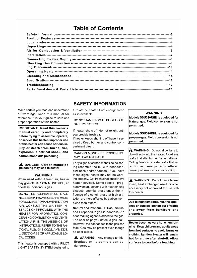
IMPORTANT : Instal l equipmentshutoff valve in an accessible location.The equipment shutoff valve is for turn-ing on or shutting off the gas to theappliance. Apply pipe joint sealantlightly to male threads. This will pre-vent excess sealant from going intopipe. Excess sealant in pipe could re-sult in clogged heater valves.
We recommend that you install a sedi-ment trap in supply line as shown inFigure 7. Locate sediment trap whereit is within reach for cleaning. Install inpiping system between fuel supply andheater. Locate sediment trap wheretrapped matter is not likely to freeze. Asediment trap traps moisture andcontaminants. This keeps them fromgoing into heater controls. If sedimenttrap is not installed or is installedincorrectly, heater may not run properly.
CHECKING GASCONNECTIONS
Figure 8 - Equipment Shutoff Valve
Pressure Testing GasSupply Piping SystemTest Pressures In Excess Of 1/2PSIG(3.5kPa)1. Disconnect heater with its appliance
main gas valve (control valve) andequipment shutoff valve from gassupply piping system. Pressures inexcess of 1/2 PSIG will damageheater regulator.
2. Cap off open end of gas pipe whereequipment shutof f valve wasconnected.
3. Pressurize supply piping system byeither using compressed air or open-ing gas supply tank valve.
4. Check all joints of gas supply pipingsystem. Apply mixture of liquid soapand water to gas joints. Bubblesforming show a leak.
5. Correct all leaks at once.6. Reconnect heater and equipment
shutoff valve to gas supply. Check re-connected fittings for leaks.
Test Pressures Equal To or LessThan 1/2 PSIG(3.5 kPa)1. Close equipment shutoff valve (see
Figure 8).2. Pressurize supply piping system by
either using compressed air or open-ing natural supply tank valve.
3. Check all joints from gas meter toequipment shutoff valve (see Figure9). Apply mixture of liquid soap andwater to gas joints. Bubbles formingshow a leak.
4. Correct all leaks at once.
Pressure Testing HeaterGas Connections1. Open equipment shutoff valve (see
Figure 8).2. Open gas supply tank valve.3. Make sure control knob of heater is in
the OFF position.4. Check all joints from equipment
shutoff valve to control valve (see Fig-ure 9). Apply mixture of liquid soapand water to gas joints. Bubblesforming show a leak.
CAUTION: Make sure externalregulator has been installed betweengas supply and heater. See guidelinesunder Connecting to Gas Supply.
WARNING: Never use an openflame to check for a leak. Apply a mix-ture of liquid soap and water to alljoints. Bubbles forming show a leak.Correct all leaks at once.
WARNING: Test all gas pipingand connections for leaks after install-i ng o r s e rv i c ing . Co r rec t a l lleaks at once.
Figure 7 - Gas Connection
* Purchase the optional CSA design-certified equipment shutoff valve fromyour dealer.** Minimum inlet pressure for purposeof input adjustment.
In the State of Massachusetts thegas cock must be a T handle type.The State of Massachusetts re-quires that a flexible appliance con-nector cannot exceed three feet inlength.
Installation must include an equip-ment shutoff valve, union, and plugged1/8" NPT tap. Locate NPT tap withinreach for test gauge hook up. NPT tapmust be upstream from heater (seeFigure 7).
Figure 6 - External Regulator With Vent Pointing Down
NG Models:5”-10.5” W.C. supply pressureGas supplier provides external regu-lator for natural gas.
LP Models:11”-14” W.C. supply pressureGas supplier provides externalregulator for propane gas.

10
Make sure log sits flat on firebox floor.
IMPORTANT: Make sure log does notcover any burner ports (see Figure 10).
Figure 9 - Checking Gas Joints
Figure 10- Installing Log Set (Top View)
LOG PLACEMENT
FIG (3)STEP 2: Install log 2 onto the two slotsin the middle plate.
FIG (1)
FIG (2)STEP 1: Install log 1 onto the two slotsin the rear plate.
FIG (4)STEP 3: Insert the two pins on the bot-tom of log 3 into the two holes on fire-box floor.
FIG (5)STEP 4: Place log 4 on log 1 and log 3,as shown.Note: Log 4 will contact inside ofheater.
FIG (6)STEP 5: Insert the recessed hole onthe bottom of log 5 onto the pin on log1, with the other end of log 5 placedon log 4, as shown.
FIG (7)STEP 6: Place log 6 on log 1 and log3.Note: Log 6 will contact inside ofheater.
FIG (8)STEP 7: Insert the recessed hole onthe bottom of log 7 onto the pin on log2, with the other end placed on log 3.
It is very important to install the logsexactly as instructed. Do not modifylogs. Only use logs supplied withheater.
WARNING: Failure to positionthe parts in accordance with thesediagrams or failure to use only partsspecifically approved with this heatermay result in property damage orpersonal injury.
CAUTION: After installation andperiodically thereafter, check to en-sure that no yellow flame comes incontact with any log. With the heaterset to High, check to see if yellowflames contact any log. If so, reposi-tion logs according to the log instal-lation instructions in this manual. Yel-low flames contacting logs will cre-ate soot.
Pressure Testing Heater GasConnectionsContinued5. Correct all leaks at once.6. Light heater (see Operating Heater).
Check all other internal joints forleaks.
7. Turn off heater (see To Turn Off GasAppliance).

11
OPERATING HEATERFOR YOUR SAFETY
READ BEFORE LIGHTING
A. This appliance is equipped with anignition device which automaticallylights the pilot. Do not try to light thepilot by hand.
B. BEFORE LIGHTING smel l a l laround the appliance area for gas.Be sure to smell next to the floorbecause some gas is heavier thanair and will settle on the floor.
WHAT TO DO IF YOU SMELL GASl Do not try to light any appliance.l Do not touch any electrical switch; do
not use any phone in your building.l Immediately call your gas supplier
from a neighbor’s phone. Follow thegas supplier’s instructions.
l If you cannot reach your gas supplier,call the fire department.
REMOTE CONTROLOPERATING INSTRUCTION
Note: If operating by remote control,you must set the Control Knob onELECTRIC position. (See Figure 11) Donot set the control knob between thelocked position, otherwise there willbe no power to the heater.1. STOP! Read the safety information
above.2. Disconnect or turn off all electric
power to heater.3. This appliance is equipped with an
ignition device which automaticallylights the pilot. Do not try to light thepilot by hand.
4. Wait five (5) minutes to clear out anygas. Then smell for gas aroundheater including near floor. If yousmell gas, STOP! Follow “B” in thesafety information above. If you don’tsmell gas, go to the next step.
5. Plug into a properly grounded three-prong receptacle, and install threeAAA batteries in remote. A high pitchsound will occur and red power lighton front of heater will be lit.
6. Make sure Control Knob is in ElectricPosition.
7. Point remote at bottom front ofheater, press IGN/OFF button, anelectric spark will ignite the pilot, andgreen light on front of heater will belit.
Note: When operating heater for thefirst time, the ignition period may be30 seconds or longer. This will al-low air to exit from the gas system.
Note: The pilot is located on back offront burner. If pilot does not stay lit,contact a qualified service personor gas supplier for repairs.
Note: If the appears on the controlboard, press the button, thenpress LOCK button to unlock.
Figure 11 - Manual ON/OFF Button Location
(With access panel removed)
Figure 12 - On/Off SwitchFunction of Manual ON/OFF Button andPower ON/OFF Switch If your remote transmitter is lost or doesnot funct ion, you can press theManual ON/OFF Button on front ofheater in order to manually operate yourheater. (See Figure 11)
Note: To operate your heater the ON/OFF switch on back of heater mustbe in the ON position. The RED lighton the front of heater indicates thereis electrical power to your heaterwhen the ON/OFF switch is in the ONposition. The GREEN light on thefront of heater indicates the pilot lightis ON. (See Figure 12)
Note: Please wait for one minuteto l ight again after shutt ing offheater.
WARNING: If you do not fol-low these instructions exactly, a fireor explosion may result causingproperty damage, personal injury orloss of life.
CAUTION: Do not try to adjustheating levels by using the equip-ment shutoff valve.
NOTICE: During initial opera-tion of new heater, logs will giveoff a paper-burning smell. Orangeflame will also be present. Open awindow to vent smell. This will onlylast a few hours.
C. Use only your hand to push control.Never use tools. If the appliancedoes not operate, don't try to repairit, call a qualified service technicianor gas supplier. Force or attemptedrepair may result in a f i re orexplosion.
D. Do not use this appliance if any parthas been under water. Immediatelycall a qualified service technician toinspect the appliance and to replaceany part of the control system andany gas control which has been un-der water.

12
Fig 15 - Control board
SETTING TIMER1. AUTO ON:With burner off, press TIMER button.Then press or to change to thescheduled time, then press the TIMERbutton again, the TIMER starts timingand the TIMER will flash and the greenoperation light flashes. Burner will au-tomatically come on at set time.
2. AUTO OFF:With burner operating, press TIMERbutton. Then press or to changeto the scheduled time, then press theTIMER button again, the TIMER startstiming and the TIMER will flash and thegreen operation flashes. Burner will au-tomatically shut off at set time.
TO TURN OFF GAS TO APPLIANCE
Shut off heater1. Press the IGN/OFF button.2. Set Switch on OFF position or un-plug the electric power to the heater.(See Figure 12)
8. Press BURNER button for desiredburner operation.
AUTO: Burner will automatically turnon and off.
MAN: Burner operates continuously.9. If the appliance will not operate, fol-
low the instructions “To Turn Off GasTo Appliance” and call your servicetechnician or gas supplier.
Fig 13 - Front of Remote Control
SETTING CLOCKPress CLOCK button for hours orminutes. Press or for correct time.Press CLOCK button again to set time.
LOCKING REMOTE CONTROL(child proof)1.Key press locking:Press LOCK button, a symbol willappear on the LCD.2.Key-press unlocking:Press▼, then press LOCK button tounlock.
OPERATING FANPress FAN button for desired fanoperation.AUTO: Blower will come on severalminutes after burner comes on and willgo off several minutes after burner goesoff.MAN: Blower operates continuously.OFF: Blower is off.
MANUAL OPERATINGINSTRUCTIONSWe provide the manual control sys-tem just in case of power shortage.Install battery for Manual Ignitor:1. Unscrew the ignitor cap.2. Insert a AAA type battery with its an-
ode (“+”) pointing out.3. Screw the ignitor cap back.Note: We recommend that the batterybe taken out of the ignitor when thepower supply gets right.
LIGHTING INSTRUCTIONS If power is off, you can operate thefireplace manually.1. STOP! Read the safety information
on page 11.2. Check that gas supply to heater is
on.3. Open bottom front access panel.4. Push in gas Control Knob slightly
and turn clockwise to the OFFposition. If Control Knob is on ELEC-TRIC position, press in the ControlKnob and turn counterclockwise to OFF position.
NOTE: Knob cannot be turned fromPILOT/IGN to “OFF” unless knob ispushed in slightly. Do not force.
Fig 14 - Back of Remote Control(cover removed)
OPERATING HEATERContinued
SETTING TEMPERATUREWith burner is on “Auto” position, press
or to change to the desiredtemperature.

13
TO TURN OFF GAS TO APPLIANCE
Push in gas Control Knob slightly andturn clockwise the OFF position. Donot force.
When electric power is available andelectric operation is desired, turn clock-wise to OFF position for one minute.Then press down knob and rotate clock-wise to ELECTRIC position.
Do not operate between lockedposition.
MANUAL LIGHTINGPROCEDURE(match light)
1. Open front door.2. Follow steps 1 through 5 under
MANUAL OPERATING LightingInstructions.
3. With Control Knob in PILOT/IGNposition, strike match, and holdnear pilot. Press in Control Knob,pilot should light.
4. Keep Control Knob pressed in for 30seconds after lighting pilot. After 30seconds, release Control Knob. Fol-low step 9 under MANUAL OPER-ATING Lighting Instructions.
Figure 16 - Manual Control
5. Wait five (5) minutes to clear outany gas. Then smell for gas, in-cluding near the floor. If you smellgas, STOP! Follow “B” in the safetyinformation on page 11. If you donot smell gas, go to the next step.
6. Push in gas control slightly andturn counterclockwise to PI-LOT/IGN and depress for five (5)seconds.
NOTE: The first t ime that theheater is operated after connect-ing the gas supply, the controlknob should be depressed forabout thirty (30) seconds. This willallow air to bleed from the gassystem.
7. With Control Knob pressed in, pushand release the ignitor button.This will light the pilot. If needed,keep pressing ignitor button untilpilot lights.
8. Keep Control Knob depressed forten (10) seconds after l ightingpilot. If pilot goes out, repeat steps6, 7 and 8.
9. Turn counterclockwise to “ON”position. Do not operate betweenlocked positions.
MANUAL OPERATINGINSTRUCTIONSContinued

14
Figure 17 - Correct Pilot FlamePattern
Figure 18 - Incorrect Pilot Flame Pattern
BURNER FLAME PATTERNFigure 19 shows a correct burner flamepattern. Figure 20 shows an incorrectburner flame pattern. If burner flame isincorrect:l Turn heater off (see TO TURN OFF
GAS TO APPLIANCE)l See troubleshooting
Figure 19 - Correct Flame Patternwith heater set to High Flame
Figure 20 - Incorrect Flame Patternwith heater set to High Flame
CLEANING AND MAIN-TENANCE
WARNING: Disconnect power be-fore attempting any maintenance orcleaning to reduce the risk of fire , elec-tric shook or personal injury. Turn offheater and let cool before cleaning.
Figure 21 - Control Module Access
DISCONNECT FAN1. Remove screws from the fan bracket
panel, pull the fan bracket panel outto remove. Disconnect two wiresfrom fan T-stat Switch.
2. Mark or tag each wire removed forits exact reconnection. Remove thefour screws from the fan. Wheninstalling, reverse the steps above.(See Figure 22 and Figure 25)
Figure 22 - Fan Access
CLEANING BURNER INJECTORHOLDER AND PILOT AIR INLET HOLEWe recommend that you clean the unitevery 2,500 hours of operation or everythree months.
The primary air inlet holes allow theproper amount of air to mix with thegas. This provides a clean burningflame. Keep these holes clear of dust,dirt, lint, and pet hair. Clean these airinlet holes prior to each heatingseason. Blocked air holes will createsoot. We recommend that you clean theunit every three months during opera-tion and have heater inspected yearlyby a qualified service person.
DISCONNECT WIRING OR CONTROLMODULE1. Remove screws from the rear con-
trol panel, take out thermostat sens-ing bulb from the clip, then discon-nect the wires from control module.
2. Remove two screws and hex nuts,securing control module. Wheninstalling, reverse the steps above.(See Figure 21 and Figure 25)
CAUTION: Label all wires prior tod isconnect ion when serv ic ingcontrols. Wiring errors can cause im-proper and dangerous operation.Verify proper operation after servicing.
WARNING: Failure to keep pri-mary/air openings of burners cleanmay result in sooting and propertydamage.
CAUTION: You must keep controlareas, burner, and circulating air pas-sageways of heater clean. Inspectthese areas of heater before eachuse. Have heater inspected yearly bya qualified service person. Heatermay need more frequent cleaning dueto excessive lint from carpeting, bed-ding material, pet hair, etc.
INSPECTING FLAME PATTERNCheck pilot flame pattern and burnerflame patterns often.PILOT FLAME PATTERNFigure 17 shows a correct pilot flamepattern. Figure 18 shows an incorrectpilot flame pattern. The incorrect pilotflame is not touching the thermocouple.This will cause the thermocouple tocool. When the thermocouple cools, theheater will shut down. If pilot flame pat-tern is incorrect, as shown in Figure18.l Turn heater off (see TO TURN OFF GAS TO APPLIANCE)l See troubleshooting

15
Figure 24 - Pilot Air Inlet Hole
Figure 23 - Burner Primary AirInlet
MAIN BURNERPeriodically inspect all burner flame holeswith the heater running. All slotted burnerflame holes should be open with yellowflame present. All round burner flameholes should be open with a small blueflame present. Some burner flame holesmay become blocked by debris or rust,with no flame present. If so, turn off heaterand let cool. Either remove blockage orreplace burner. Blocked burner flameholes will create soot.
We recommend you keep the burnerand pilot assembly clean and free ofdust and dirt.To clean these parts we recommendusing compressed air no greater than30 PSI. Your local computer store,hardware store, or homecenter may carry compressed air in acan. You can use a vacuum cleaner inthe blow position. If using com-pressed air in a can, please follow thedirections on the can. If you don't fol-low directions on the can, you coulddamage the pilot assembly.1. Shut off the unit, including the
pilot. Allow the unit to cool forat least thirty minutes.
2 . I nspec t bu rne r , p i l o t andpr imary a i r i n le t ho les oninjector holder for dust and dirt(See Figure 23).
3 . B l o w a i r t h r o u g h t h eports/slots and holes in theburner.
4. Check t he i n jec to r ho lde rloca ted a t the end o f theburner tube again. Removeany large particles of dust, dirt,lint, or pet hair with a soft clothor vacuum cleaner nozzle.
5. Blow air into the primary airholes on the injector holder.
6. In case any large clumps ofdust have now been pushedinto the burner repeat steps 3and 4.
Clean the pilot assembly also. A yel-low tip on the pilot flame indicates dustand dirt in the pilot assembly. Thereis a small air inlet hole about twoinches from where the pilot flamecomes out of the pilot assembly (seeFigure 24). With the unit off, lightly blowair through the air inlet hole. You mayblow through a drinking straw if com-pressed air is not available.
Figure 25 - Override Control System Diagram
CABINETAir Passagewaysl Use a vacuum cleaner or pressur-
ized air to clean.Exteriorl Use a soft cloth dampened with a
mild soap and water mixture. Wipethe cabinet to remove dust.
Logsl If you remove logs for cleaning, re-
fer to Installing Logs to properly re-place logs.
l Replace logs if broken or chipped(dime size or larger).

16
SPECIFICATIONS
Btu (Variable) 32,000 32,000Gas Type LP Gas Natural GasIgnition Automatic or Electronic Automatic or ElectronicManifold Pressure 9" W.C. 4" W.C.Inlet Gas Pressure (In. of water)* Maximum 14" 10.5" Minimum 11" 5"Dimensions, Inches (H×W×D) Heater 26 1/8"×42 5/16” ×16 7/8" 26 1/8"×42 5/16” ×16 7/8" Carton 18 7/8"×35 7/16” ×30” 18 7/8"×35 7/16” ×30”Weight, lbs Stove 108 108 Shipping 117 117Volts 120 120Watts 32 32
*For purposes of input adjustment
REPLACEMENT PARTSUse only original replacement parts.This will protect your warranty cover-age for parts replaced under warranty.
PARTS UNDER WARRANTYContact authorized dealers of thisproduct. If they can't supply originalreplacement part(s) call the numberon the back o f manua l . Whencontacting your dealer or PRO-COM,have ready:l Your namel Your addressl Model and serial numbers of your heaterl How heater was malfunctioningl Type of gas used (Propane/LP or Natural gas/NG)l Purchase datel Warranty card.Usually, we will ask you to return thedefective part to the factory.
SSU320RHL-GBSSU320RHL-BSSU320RHL-GSSU320RHL-S
SSU320RHN-GB SSU320RHN-B SSU320RHN-G SSU320RHN-S
ACCESSORIESPurchase these heater accessoriesfrom your local dealer. If they can notsupply these accessories, contactPRO-COM for information. You can alsowrite to the address listed on the frontof this manual.
PARTS NOT UNDER WARRANTYContact authorized dealers of thisproduct. If they can’t supply original re-placement part(s) call PRO-COM’s toll-free number (877)886-5989.
TECHNICAL SERVICEFor questions about instal lation,operation, or troubleshooting, contactPRO-COM toll -free at (877)886-5989.
SIDE SHELF
17
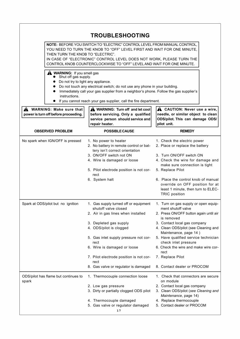
TROUBLESHOOTING
WARNING: Make sure thatpower is turn off before proceeding.
WARNING: Turn off and let coolbefore servicing. Only a qualifiedservice person should service andrepair heater.
CAUTION: Never use a wire,needle, or similar object to cleanODS/pilot. This can damage ODS/pilot unit.
OBSERVED PROBLEM
No spark when IGN/OFF is pressed
Spark at ODS/pilot but no ignition
ODS/pilot has flame but continues tospark
POSSIBLE CAUSE
1. No power to heater2. No battery in remote control or bat-
tery isn’t correct orientation3. ON/OFF switch not ON4. Wire is damaged or loose
5. Pilot electrode position is not cor-rect
6. System halt
1. Gas supply turned off or equipmentshutoff valve closed
2. Air in gas lines when installed
3. Depleted gas supply4. ODS/pilot is clogged
5. Gas inlet supply pressure not cor-rect
6. Wire is damaged or loose
7. Pilot electrode position is not cor-rect
8. Gas valve or regulator is damaged
1. Thermocouple connection loose
2. Low gas pressure3. Dirty or partially clogged ODS pilot
4. Thermocouple damaged5. Gas valve or regulator damaged
REMEDY
1. Check the electric power2. Place or replace the battery
3. Turn ON/OFF switch ON4. Check the wire for damage and
make sure connection is tight5. Replace Pilot
6. Place the control knob of manualoverride on OFF position for atleast 1 minute, then turn to ELEC-TRIC position
1. Turn on gas supply or open equip-ment shutoff valve
2. Press ON/OFF button again until airis removed
3. Contact local gas company4. Clean ODS/pilot (see Cleaning and
Maintenance, page 14 )5. Have qualified service technician
check inlet pressure6. Check the wire and make wire cor-
rect7. Replace Pilot
8. Contact dealer or PROCOM
1. Check that connectors are secureon module
2. Contact local gas company3. Clean ODS/pilot (see Cleaning and
Maintenance, page 14)4. Replace thermocouple5. Contact dealer or PROCOM
WARNING: If you smell gasl Shut off gas supply.l Do not try to light any appliance.l Do not touch any electrical switch; do not use any phone in your building.l Immediately call your gas supplier from a neighbor’s phone. Follow the gas supplier’s instructions.l If you cannot reach your gas supplier, call the fire department.
NOTE: BEFORE YOU SWITCH TO “ELECTRIC” CONTROL LEVEL FROM MANUAL CONTROL,YOU NEED TO TURN THE KNOB TO “OFF” LEVEL FIRST AND WAIT FOR ONE MINUTE,THEN TURN THE KNOB TO “ELECTRIC”.IN CASE OF “ELECTRONIC” CONTROL LEVEL DOES NOT WORK, PLEASE TURN THECONTROL KNOB COUNTERCLOCKWISE TO “OFF” LEVEL AND WAIT FOR ONE MINUTE.

18
TROUBLESHOOTINGContinued
OBSERVED PROBLEM
ODS/pilot has flame but burner doesnot light
Delayed ignition at burner
Burner backfiring during combustion
Slight smoke or odor during initial op-eration
Dark residue on logs or inside of fire-place
Heater produces a clicking/tickingnoise just after burner is lit or shut off
White powder residue forming withinburner box or on adjacent walls or fur-niture
POSSIBLE CAUSE
1. Burner injector clogged
2. Inlet gas pressure is too low
3. Thermocouple leads disconnectedor improperly connected
4. Batteries weak
1. Manifold pressure is too low2. Burner parts or injector clogged
1. Damaged burner injector
2. Excessive supply pressure dam-aged regulator
1. Residues from manufacturing pro-cesses
2. Not enough air
3. Excessive supply pressure damagedregulator
1. Improper log placement
2. Air holes at burner inlet blocked
3. Burner flame holes blocked
1. Metal expanding while heating orcontracting while cooling
1. Heated vapors from furniture polish,wax, carpet cleaners, etc. turn intowhite powder residue
REMEDY
1. Clean burner (see Cleaning andMaintenance, page 14) or replaceburner injector
2. Contact local gas company
3. Reconnect leads (see wi r ingdiagram)
4. Replace batteries
1. Contact local gas company2. Clean burner (see Cleaning and
Maintenance, page 14)
1. Clean burner injector (see Clean-ing and Maintenance, page 14)
2. Replace gas regulator
1. Problem will stop after a few hoursof operation.
2. Check burner for dirt and debris. Iffound, clean burner. (See Cleaningand Maintenance, page 14)
3. Replace gas regulator
1. Properly locate logs (see LogPlacement, page 10)
2. Clean out air holes at burner inletPeriodically repeat as needed
3. Remove blockage or replace burner
1. This is common with most heaters.If noise is excessive, contact quali-fied service person
1. Turn heater off when using furniturepolish, wax, carpet cleaner, or simi-lar products

19
TROUBLESHOOTINGContinued
REMEDY
1. Ventilate room. Stop using odorcausing products while heater isrunning
2. Locate and correct all leaks (seeChecking Gas Connections, Page9)
1. Open window and/or door for, venti-lation
2. Contact local propane/LP gas com-pany
3. Clean ODS/pilot (see Cleaning Page14)
1. Locate and correct all leaks (seeChecking Gas Connections, Page9)
1. Remove foreign matter
2. Locate and correct all leaks (seeChecking Gas Connections, Page9)
1. Refer to Air for Combustion and Ven-tilation requirements, Page 5
POSSIBLE CAUSE
1. Heater is burning vapors from paint,hair spray, glues, etc. (See IMPOR-TANT statement at beginning oftroubleshooting)
2. Gas leak. See WARNING Statementat beginning of troubleshooting
1. Not enough fresh air is available
2. Low line pressure
3. ODS/pilot is partially clogged
1. Gas leak. See WARNING Statementat beginning of troubleshooting
1. Foreign matter between control valveand burner
2. Gas leak. See WARNING Statementat beginning of troubleshooting
1. Not enough combustion/ventilationair
OBSERVED PROBLEM
Heater produces unwanted odors
Heate r shu ts o f f i n use (ODSoperates)
Gas odor exists even when heater isshut off
Gas odor during combustion
Moisture/condensation on windows
20
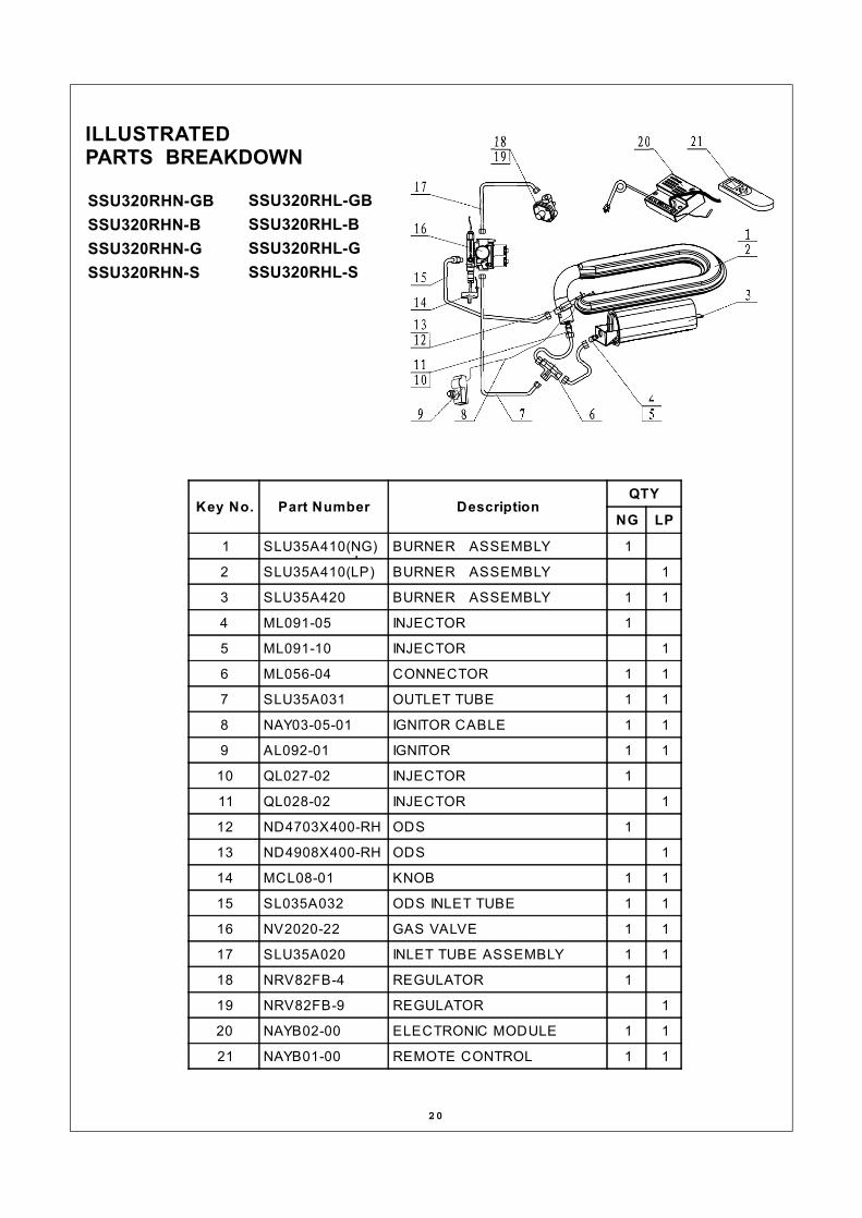
ILLUSTRATEDPARTS BREAKDOWN
SSU320RHN-GBSSU320RHN-BSSU320RHN-GSSU320RHN-S
SSU320RHL-GBSSU320RHL-BSSU320RHL-GSSU320RHL-S
Key No. Part Number DescriptionQTY
NG LP
1 SLU35A410(NG) BURNER ASSEMBLY 1
2 SLU35A410(LP) BURNER ASSEMBLY 1
3 SLU35A420 BURNER ASSEMBLY 1 1
4 ML091-05 INJECTOR 1
5 ML091-10 INJECTOR 1
6 ML056-04 CONNECTOR 1 1
7 SLU35A031 OUTLET TUBE 1 1
8 NAY03-05-01 IGNITOR CABLE 1 1
9 AL092-01 IGNITOR 1 1
10 QL027-02 INJECTOR 1
11 QL028-02 INJECTOR 1
12 ND4703X400-RH ODS 1
13 ND4908X400-RH ODS 1
14 MCL08-01 KNOB 1 1
15 SL035A032 ODS INLET TUBE 1 1
16 NV2020-22 GAS VALVE 1 1
17 SLU35A020 INLET TUBE ASSEMBLY 1 1
18 NRV82FB-4 REGULATOR 1
19 NRV82FB-9 REGULATOR 1
20 NAYB02-00 ELECTRONIC MODULE 1 1
21 NAYB01-00 REMOTE CONTROL 1 1

21
ILLUSTRATEDPARTS BREAKDOWNSSU320RHN-GBSSU320RHN-BSSU320RHN-GSSU320RHN-S
SSU320RHL-GBSSU320RHL-BSSU320RHL-GSSU320RHL-S
KeyNo. Part Number Description
QTY
SSU320RHN-GBSSU320RHL-GB
SSU320RHN-BSSU320RHL-B
SSU320RHN-GSSU320RHL-G
SSU320RHN-SSSU320RHL-S
1 SLU35A102-GB TOP 1
SLU35A102-B TOP 1
SLU35A102-G TOP 1
SLU35A102-S TOP 1
2 SLU35A130-GB DOOR WITH SCREEN 1
SLU35A130-B DOOR WITH SCREEN 1
SLU35A130-G DOOR WITH SCREEN 1
SLU35A130-S DOOR WITH SCREEN 1
3 SLU35A106-GB ACCESS PANEL 1
SLU35A106-B ACCESS PANEL 1
SLU35A106-G ACCESS PANEL 1
SLU35A106-S ACCESS PANEL 1
4 SLU35A101C BACK 1 1 1 1
5 SLU35A103 LOUVER ASSEMBLY 1 1 1 1
6 SLU35A201 FIREBOX ASSEMBLY 1 1 1 1
7 SLU35A108 CABINET BOTTOM 1 1 1 1
8 SLU35A116 LOWER FRONT PANEL 1 1 1 1
9 SLU35A401 FIREBOX FLOOR 1 1 1 1
10 SLU35A132 DOOR HINGE 1 1 1 1
11 SLU35A131 DOOR HINGE 1 1 1 1
12 SLU35A105 SIDE 2 2 2 2


![Direct Vent Gas Fired Hot Water Boiler INSTALLATION, … · 2015-08-25 · P/N 3771201, Rev.A [01/09] USC SERIES Direct Vent Gas Fired Hot Water Boiler INSTALLATION, OPERATION & MAINTENANCE](https://img.pdfslide.net/doc/110x75/5f9abe8b3e25b46d9e0a5903/direct-vent-gas-fired-hot-water-boiler-installation-2015-08-25-pn-3771201-reva.jpg)