Embed Size (px)
Citation preview

MODEL NUMBER: _________________________
SERIAL NUMBER: _________________________
DATE PURCHASED:________________________
Owner’s ManualHomelink Upgradeable Manual Transfer Switch
SAVE THIS MANUAL FOR FUTURE REFERENCE
Para español , visita: http://www.generac.com/service-support/product-support-lookup
Pour le français, visiter : http://www.generac.com/service-support/product-support-lookup
Register your Generac product at:WWW.GENERAC.COM
1-888-GENERAC(888-436-3722)
(000209b)
WARNINGLoss of life. This product is not intended to be used in a critical life support application. Failure to adhere to this warning could result in death or serious injury.

ii Homelink Upgradeable Manual Transfer Switch Owner’s Manual
(000005)
WARNINGCalifornia Proposition 65. This product contains or emits chemicals known to the state of California to cause cancer, birth defects, and other reproductive harm.
(000004)
WARNINGCalifornia Proposition 65. Engine exhaust and some of its constituents are known to the state of California to cause cancer, birth defects, and other reproductiveharm.
Models:
6852 MTS 30A 8-10 CKT Pre-Wired Switch
6853 Kit, MTS 30A 8-10 CKT Pre-Wired Switch, 30A Cord and Resin Power Inlet Box
6854 Kit, MTS 30A 8-10 CKT Pre-Wired Switch, 30A Cord and Aluminum Power Inlet Box
9854 MTS 50A 10-16 CKT Pre-Wired Switch
9855 Kit, MTS 50A 10-16 CKT Pre-Wired Switch, 50A Cord and Aluminum Power Inlet Box
6869 Manual to Automatic Upgrade Kit

Table of Contents
Section 1: Introduction and Safety
Introduction ..........................................................1
Safety Rules .........................................................1Safety Messages .........................................................1
Safety Symbols and Meanings ...........................2
Section 2: General Information
Unpacking ............................................................3
Equipment Description .......................................3Transfer Switch Mechanism ........................................3
Transfer Switch Data Decal ................................3
Transfer Switch Enclosure .................................3
Power Inlet Box (if equipped) .............................4
Safe Use of Transfer Switch ...............................4
Load Management Options .................................4
Section 3: Installation
Mounting the Transfer Switch ............................5
Mounting the Power Inlet Box ............................5
Connecting Power Source and Load Lines .......6
Connecting Front Panel Wiring ..........................6
Installing Branch Circuit Conductors – USA Installations ........................................6
Installing Branch Circuit Conductors – Canadian Installations ...............................7
Installing Breakers ...............................................7Breakers Listed for Use ...............................................7
Portable Generator Grounding Requirements ..7
Automatic Upgrade Kit Installation ....................8
Section 4: Operation
Functional Tests .................................................. 9
Manual Operation ................................................ 9Transfer Mechanism Manual Operation ......................9
Close to Generator Source Side .................................9
Return to Utility Source Side .....................................10
Voltage Checks .................................................. 10Utility Voltage Checks ...............................................10
Generator Voltage Checks ........................................10
Generator Tests Under Load ............................ 10
Checking Electric Operation (Portable Generator Only) .......................... 10
Checking Automatic Operation (Automatic HSB Generator Only) .............. 11
Installation Summary ........................................ 11
Shutting Generator Down While Under Load .... 12
Section 5: Drawings and Diagrams
Installation Drawing No. 0K8843-B .................. 13
Interconnection Drawing No. 0K8845-A (Manual Transfer Connections) ................. 14
Interconnection Drawing No. 0K8844-C (Automatic Transfer Connections) ............ 15
Automatic Transfer Switch Owner’s Manual iii

Table of Contents
This page intentionally left blank.
iv Automatic Transfer Switch Owner’s Manual

Introduction and Safety
Section 1: Introduction and Safety
IntroductionThank you for purchasing a Generac Power Systems Inc.product. This unit has been designed to provide high-performance, efficient operation, and years of use whenmaintained properly.
Read this manual thoroughly and understand all of theinstructions, cautions, and warnings before using thisequipment. If any section of the manual is notunderstood, contact your nearest IndependentAuthorized Service Dealer (IASD) or contact GeneracCustomer Service at 1-888-436-3722, orwww.generac.com with any questions or concerns.
The owner is responsible for proper maintenance andsafe use of the equipment. Before operating or servicingthis transfer switch:
• Study all safety information in this manual and onthe product carefully.
• Become familiar with this manual and the unitbefore use.
• Refer to Installation for instructions on finalassembly procedures. Follow the instructionscompletely.
Save these instructions for future reference. ALWAYSsupply this manual to any individual that will use thismachine.
The information in this manual is accurate based on
products produced at the time of publication. Themanufacturer reserves the right to make technicalupdates, corrections, and product revisions at any timewithout notice.
Safety RulesThe manufacturer cannot anticipate every possiblecircumstance that might involve a hazard. The safetyinformation in this manual, and on tags and decalsaffixed to the unit are, therefore, not all-inclusive. If usinga procedure, work method or operating technique thatthe manufacturer does not specifically recommend, verifythat it is safe for others. Also make sure the procedure,work method or operating technique utilized does notrender the equipment unsafe.
Safety Messages
Throughout this publication, and on tags and decalsaffixed to the transfer switch, DANGER, WARNING, andCAUTION blocks are used to alert personnel to specialinstructions about a particular operation that may behazardous if performed incorrectly or carelessly. Observethem carefully. Their definitions are as follows:
NOTE: Notes contain additional information important toa procedure and will be found within the regular text ofthis manual.
These safety alerts cannot eliminate the hazards thatthey indicate. Common sense and strict compliance withthe special instructions while performing the action orservice are essential to preventing accidents.
(000001)
DANGERIndicates a hazardous situation which, if not avoided, will result in death or serious injury.
(000002)
WARNINGIndicates a hazardous situation which, if not avoided,could result in death or serious injury.
(000003)
CAUTIONIndicates a hazardous situation which, if not avoided,could result in minor or moderate injury.
Homelink Upgradeable Manual Transfer Switch Owner’s Manual 1

Introduction and Safety
Safety Symbols and Meanings
• Any voltage measurements should be performedwith a meter that meets UL3111 safety standards,and meets or exceeds overvoltage class CAT III.
(000129)
DANGERElectrocution. High voltage is present at transfer switch and terminals. Contact with live terminals will result in death or serious injury.
(000104)
DANGERElectrocution. Water contact with a power source, if not avoided, will result in death or serious injury.
(000145)
DANGERElectrocution. In the event of electrical accident, immediately shut power OFF. Use non-conductive implements to free victim from live conductor. Apply first aid and get medical help. Failure to do so will result in death or serious injury.
(000237)
DANGERElectrical backfeed. Use only approved switchgear to isolate generator from the normal power source.Failure to do so will result in death, serious injury, and equipment damage.
(000195)
DANGERElectrocution, equipment and property damage. Handle transfer switches carefully when installing. Never install a damaged transfer switch. Doing so could result in death or serious injury, equipment and property damage.
(000123)
DANGERElectrocution. Turn utility supply OFF before working on utility connections of the transfer switch. Failure to do so will result in death or serious injury.
(000157)
DANGERElectrocution. Do not disable or modify theconnection box door safety switch. Doing sowill result in death or serious injury.
Automatic start-up. Disconnect utility power and render unit inoperable before working on unit. Failure to do so will result in death or serious injury.
(000191)
DANGER
(000155a)
WARNINGElectric shock. Only a trained and licensed electrician should perform wiring and connections to unit. Failure to follow proper installation requirements could result in death, serious injury, and equipment or property damage.
(000100a)
WARNINGConsult Manual. Read and understand manualcompletely before using product. Failure to completely understand manual and productcould result in death or serious injury.
2 Homelink Upgradeable Manual Transfer Switch Owner’s Manual

Section 2: General Information
UnpackingCarefully unpack the transfer switch. Inspect closely forany damage that might have occurred during shipment.The purchaser must file with the carrier any claims forloss or damage incurred while in transit.
Check that all packing material is completely removedfrom the switch prior to installation.
Equipment DescriptionThe transfer switch is used for transferring criticalelectrical load from a UTILITY (NORMAL) power sourceto a GENERATOR (STANDBY) power source. Thetransfer switch prevents electrical feedback between twodifferent power sources (such as the UTILITY andGENERATOR sources) and, for that reason, codesrequire it in all standby electric system installations.
The transfer switch consists of a transfer mechanism, acontrol switch, and indicator lights.
This UL listed transfer switch is for use in optionalstandby systems only (NEC article 702).
NOTE: Generator output voltage must be 240VAC. Thisswitch is not compatible with 120VAC generator outputvoltage.
Transfer Switch Mechanism
These switches (Figure 2-1) are used with a single-phase system, when the single-phase NEUTRAL line isto be connected to a neutral lug and is to be switched.The switched neutral provides compatibility with GFCIequipped generators.
Solderless, screw-type terminal lugs are standard.
The conductor size range is as follows:
This transfer switch is suitable for control of motors,electric discharge lamps, tungsten filament and electricheating equipment where the sum of motor full loadampere ratings and the ampere ratings of other loads donot exceed the ampere rating of the switch and thetungsten load does not exceed 30 percent of the switchrating.
A 50A rated switch is suitable for use on circuits capable of delivering not more than 10,000 RMS symmetrical amperes, 250 VAC maximum, when protected by a 50A maximum circuit breaker (Square D HOM, General Electric THQL, or Eaton Cutler Hammer BR).
Figure 2-1. Typical 3-Pole Transfer Mechanism
Transfer Switch Data DecalA data decal is permanently affixed to the transfer switchenclosure. Use this transfer switch only with the specificlimits shown on the data decal and on other decals andlabels that may be affixed to the switch. This will preventdamage to equipment and property.
When requesting information or ordering parts for thisequipment, make sure to include all information from thedata decal.
For future reference, record the Model and Serialnumbers in the space provided on the front cover of thismanual.
Transfer Switch EnclosureThe standard switch enclosure is a National ElectricalManufacturer’s Association (NEMA) UL Type 1 indoorenclosure.
SwitchRating
Wire Range Conductor TighteningTorque
Lug Temp. Rating
30A
50A
1/0 - 14 AWG Cu/Al
50 in-lbs (5.6 Nm)
167°F (75°C)
A Utility Lugs (N1, N2 & N3)
B Generator Lugs (E1, E2 & E3)
C Load Lugs (T1, T2 & T3)
000101
C
A
B
Homelink Upgradeable Manual Transfer Switch Owner’s Manual 3

General Information
Power Inlet Box (if equipped)The Power Inlet Box (PIB) safely connects a portablegenerator to the manual transfer switch.
Two types of enclosure are available:
• Corrosion-resistant aluminum
• Non-metallic resin
The conductor size range is as follows:
Safe Use of Transfer Switch
Before installing, operating or servicing this equipment,read the Safety Rules carefully. Comply strictly with allSafety Rules to prevent accidents and/or damage to theequipment. The manufacturer recommends that a copyof the Safety Rules be posted near the transfer switch.Also, be sure to read all instructions and informationfound on tags, labels and decals affixed to theequipment.
Publications that outline the safe installation andmanufacturing of transfer switches are the following:
• NFPA 70; National Electrical Code
• UL 1008, STANDARD FOR SAFETY-AUTOMATICTRANSFER SWITCHES
• UL67 Panel boards
NOTE: To ensure code compliance, it is essential to usethe latest version of any standard that has been adaptedby your local municipality.
Load Management OptionsLoads can be managed using a smart powermanagement system. The system can accommodate upto eight individual Smart Management Modules (SMM).*
NOTE: SMMSs are self-contained and have individualbuilt-in controllers.
*See SMM Module (available separately)
PIBRating
Wire Range Conductor TighteningTorque
Lug Temp. Rating
30A50A
8 - 14 AWG50 in-lbs (5.6 Nm)
167°F (75°C)
(000100a)
WARNINGConsult Manual. Read and understand manualcompletely before using product. Failure to completely understand manual and productcould result in death or serious injury.
4 Homelink Upgradeable Manual Transfer Switch Owner’s Manual

Section 3: Installation
Mounting the Transfer Switch
Mounting dimensions for the transfer switch enclosureare at the back of this manual. Enclosures are typicallywall-mounted. See Drawings and Diagrams.
This transfer switch is mounted in a NEMA 1 enclosure. Itcan be mounted indoors only and should be based on thelayout of installation, convenience and proximity to theutility supply and load center.
IMPORTANT NOTE: Always adhere to local electrical codes during installation.
1. Locate transfer switch where proper equipmentand clear working space can be maintained.
2. Hold transfer switch against the mounting surface.
IMPORTANT NOTE: To eliminate the possibility ofdebris contamination, never drill inside the enclosure.
3. Drill the appropriate size holes for mountinghardware at marked hole locations.
4. Mount transfer switch to mounting surface withappropriate fasteners.
NOTE: The one foot (30.5 cm) conduit can be installedon either side of the box through a removable plate.
NOTE: Transfer switch must be mounted vertically asshown in Figure 3-1.
Figure 3-1. Transfer Switch Mounting
Mounting the Power Inlet BoxInstall the Power Inlet Box (PIB) in a location thatensures generator is at least 5 feet (1.52 m) away fromwindows, doors or other openings such as dryer vents, orair conditioning units.
1. Remove front cover.
• For installations where side clearance is less than12 inches (30.5 cm) on either side, remove three(3) screws securing inlet to bottom plate.
• For installations where side clearance exceeds 12inches (30.5 cm) on both sides, remove screwsecuring bottom plate to box.
• For wiring entry into the back of the PIB, installwiring through one of the provided knockouts, ordrill an appropriate sized entry into the PIB.
• For wiring entry into the sides or top of the PIB, installwiring through one of the provided knockouts, or drillan appropriate sized entry into the PIB. Caulk aroundthe top and sides of the enclosure, as well as aroundthe cable entrance.
NOTE: To maintain NEMA 3R rating if entry is above thelevel of uninsulated live parts, use fittings listed for use inwet locations.
2. Mount PIB on building exterior in a convenientlocation (minimum 24 inches [61 cm] above grade),using the four holes provided on cabinet back.
3. Extend wiring inside PIB approximately eightinches (20.3 cm) from point of entrance.
4. Attach equipment grounding conductor to greenlead provided in PIB with wire nut (provided byinstaller).
(000123)
DANGERElectrocution. Turn utility supply OFF before working on utility connections of the transfer switch. Failure to do so will result in death or serious injury.
(000119)
Equipment malfunction. Installing a dirty or damagedtransfer switch will cause equipment malfunction and will result in death or serious injury.
DANGER
(000182a)
WARNINGEquipment damage. Only qualified service personnel may install, operate, and maintain this equipment. Failure to follow proper installation requirements could result in death, serious injury, and equipment or property damage.
000946
Homelink Upgradeable Manual Transfer Switch Owner’s Manual 5
Installation
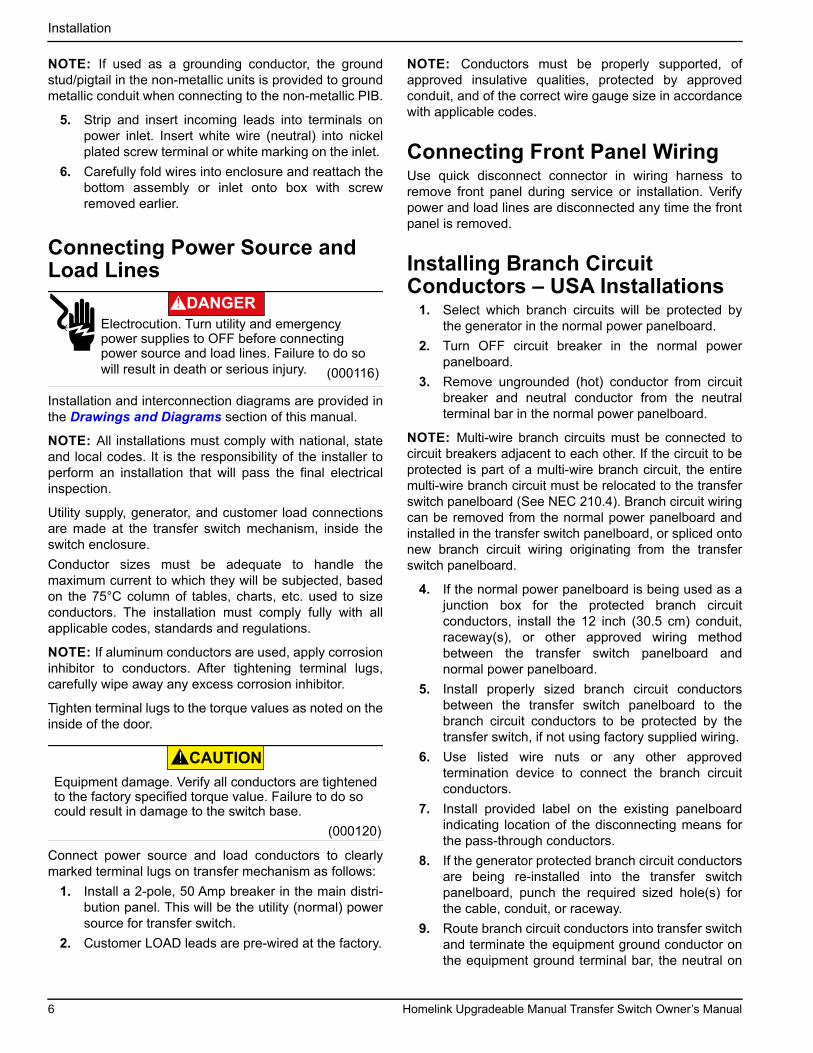
NOTE: If used as a grounding conductor, the groundstud/pigtail in the non-metallic units is provided to groundmetallic conduit when connecting to the non-metallic PIB.
5. Strip and insert incoming leads into terminals onpower inlet. Insert white wire (neutral) into nickelplated screw terminal or white marking on the inlet.
6. Carefully fold wires into enclosure and reattach thebottom assembly or inlet onto box with screwremoved earlier.
Connecting Power Source and Load Lines
Installation and interconnection diagrams are provided inthe Drawings and Diagrams section of this manual.
NOTE: All installations must comply with national, stateand local codes. It is the responsibility of the installer toperform an installation that will pass the final electricalinspection.
Utility supply, generator, and customer load connectionsare made at the transfer switch mechanism, inside theswitch enclosure.
Conductor sizes must be adequate to handle themaximum current to which they will be subjected, basedon the 75°C column of tables, charts, etc. used to sizeconductors. The installation must comply fully with allapplicable codes, standards and regulations.
NOTE: If aluminum conductors are used, apply corrosioninhibitor to conductors. After tightening terminal lugs,carefully wipe away any excess corrosion inhibitor.
Tighten terminal lugs to the torque values as noted on theinside of the door.
Connect power source and load conductors to clearlymarked terminal lugs on transfer mechanism as follows:
1. Install a 2-pole, 50 Amp breaker in the main distri-bution panel. This will be the utility (normal) powersource for transfer switch.
2. Customer LOAD leads are pre-wired at the factory.
NOTE: Conductors must be properly supported, ofapproved insulative qualities, protected by approvedconduit, and of the correct wire gauge size in accordancewith applicable codes.
Connecting Front Panel WiringUse quick disconnect connector in wiring harness toremove front panel during service or installation. Verifypower and load lines are disconnected any time the frontpanel is removed.
Installing Branch Circuit Conductors – USA Installations
1. Select which branch circuits will be protected bythe generator in the normal power panelboard.
2. Turn OFF circuit breaker in the normal powerpanelboard.
3. Remove ungrounded (hot) conductor from circuitbreaker and neutral conductor from the neutralterminal bar in the normal power panelboard.
NOTE: Multi-wire branch circuits must be connected tocircuit breakers adjacent to each other. If the circuit to beprotected is part of a multi-wire branch circuit, the entiremulti-wire branch circuit must be relocated to the transferswitch panelboard (See NEC 210.4). Branch circuit wiringcan be removed from the normal power panelboard andinstalled in the transfer switch panelboard, or spliced ontonew branch circuit wiring originating from the transferswitch panelboard.
4. If the normal power panelboard is being used as ajunction box for the protected branch circuitconductors, install the 12 inch (30.5 cm) conduit,raceway(s), or other approved wiring methodbetween the transfer switch panelboard andnormal power panelboard.
5. Install properly sized branch circuit conductorsbetween the transfer switch panelboard to thebranch circuit conductors to be protected by thetransfer switch, if not using factory supplied wiring.
6. Use listed wire nuts or any other approvedtermination device to connect the branch circuitconductors.
7. Install provided label on the existing panelboardindicating location of the disconnecting means forthe pass-through conductors.
8. If the generator protected branch circuit conductorsare being re-installed into the transfer switchpanelboard, punch the required sized hole(s) forthe cable, conduit, or raceway.
9. Route branch circuit conductors into transfer switchand terminate the equipment ground conductor onthe equipment ground terminal bar, the neutral on
Electrocution. Turn utility and emergencypower supplies to OFF before connecting power source and load lines. Failure to do so will result in death or serious injury. (000116)
DANGER
(000120)
CAUTIONEquipment damage. Verify all conductors are tightened to the factory specified torque value. Failure to do so could result in damage to the switch base.
6 Homelink Upgradeable Manual Transfer Switch Owner’s Manual

Installation
the neutral terminal bar, and the ungrounded (hot)on the circuit breaker terminal.
10. Size all conductors, raceways, conduits, andjunction boxes, if required, to the applicable NECcode articles and follow the NEC installationrequirements for the wiring method(s) selected.
NOTE: The 12 inch (30.5 cm) pre-wired whip can beshortened if needed or removed and replaced with fieldwiring. Factory-installed branch circuits and circuitbreakers can also be modified if needed. Follow allapplicable electrical codes for any field modification.
Installing Branch Circuit Conductors – Canadian Installations
1. Select which branch circuits will be protected bythe generator in the normal power panelboard.Turn the circuit breaker in the normal power panel-board to the off position.
2. Remove the ungrounded (hot) conductor from thecircuit breaker and neutral conductor from theneutral terminal bar in the normal powerpanelboard.
NOTE: If the circuit to be protected is part of a multi-wirebranch circuit, the entire multi-wire branch circuit must berelocated to the transfer switch panelboard.
3. The Canadian Electric Code prohibits the use ofthe normal power panelboard as a junction box.The generator protected branch circuit wiring mustbe relocated to a properly sized junction box, orreinstalled into the transfer switch panelboard.
4. Punch required sized hole(s) for the cable, conduit,or raceway into the transfer switch.
5. Route the branch circuit conductors into thetransfer switch and terminate the equipmentground conductor on the equipment groundterminal bar, the neutral on the neutral terminal bar,and the ungrounded (hot) on the circuit breakerterminal.
6. Size all conductors, raceways, conduits, andjunction boxes, if required, to the applicable CECcode articles and follow the CEC installationrequirements for the wiring method(s) selected.
NOTE: The 12 inch (30.5 cm) pre-wired whip can beshortened if needed or removed and replaced with fieldwiring. Factory-installed branch circuits and circuitbreakers can also be modified if needed. Follow allapplicable electrical codes for any field modification.
Installing BreakersIMPORTANT NOTE: AFCI and GFCI circuit breakersare not provided by the factory. If the circuits to beprotected require AFCI or GFCI protection, or both, thenlisted protection shall be provided by the installer.
Factory-supplied breakers can be changed by theinstaller. Install listed and labeled circuit breakerscompatible with the transfer switch (See BreakersListed for Use). Follow all applicable NEC and CECcode articles for any field modifications.
Breakers Listed for Use
Multi listed for use with one inch (2.54 cm) standard,tandem, GFCI and AFCI breakers from Siemens/Murraytype QP, Eaton type BR, and Square D type HOM. Thebreakers shall not exceed 50 Amperes rating.
See Figure 3-2. Insert tab on the breaker (A) into hookon bus (B). Push breaker into bus until it snaps intoplace.
Figure 3-2. Installing Breakers
Portable Generator Grounding RequirementsThe Upgradeable Manual Transfer Switch is designed foruse with portable generators with a bonded neutral, andused as a separately derived system. A groundingsystem and a grounding electrode system shall beconnected to the ground terminal on the portablegenerator. See NEC Article 250.30(A)(4) and (5) for codecompliance.
000362
A
B
Homelink Upgradeable Manual Transfer Switch Owner’s Manual 7

Installation
Automatic Upgrade Kit Installation
1. Turn transfer switch normal power supply circuitbreaker OFF (open).
2. Remove transfer switch cover, disconnect controlwiring to cover, and verify electrical power hasbeen turned off.
3. Disconnect normal power feeder conductors, thegenerator feeder conductors, and panelboardconductors from transfer mechanism.
4. See Figure 3-3. Remove screw (A) that holds thetransfer mechanism in place, and remove transfermechanism from the transfer switch.
Figure 3-3. Remove Transfer Mechanism
5. See Figure 3-4. Remove lower left screw (B)securing divider plate in the transfer switch.
Figure 3-4. Install Automatic Back Plate
6. Install new automatic back plate (C) in transferswitch and secure to transfer switch enclosure.
7. Remove neutral conductor from main lug onneutral bar.
8. See Figure 9. Terminate normal power neutral to main lug (D) on neutral bar.
Figure 3-5. Connection Details
9. Terminate neutral conductor from generator powerfeeder on neutral terminal bar (E) in transferswitch.
10. Terminate normal power feeder conductors to N1 andN2 (F) on transfer mechanism.
11. Terminate panelboard feeder conductors to T1 and T2(G) on transfer mechanism.
12. Terminate generator feeder conductors to E1 and E2(H) on transfer mechanism.
13. Terminate generator control wiring to N1, N2, T1,23 and 194 terminals (J) in transfer switch.
14. Install new panelboard cover and properly label allbranch circuits.
15. See Section 4 Checking Automatic Operation(Automatic HSB Generator Only) to verify propertransfer switch and generator operation.
A
B
C
G H F
D
E
J
8 Homelink Upgradeable Manual Transfer Switch Owner’s Manual
Section 4: Operation
Functional TestsFollowing transfer switch installation and interconnection,inspect the entire installation carefully. A competent,qualified electrician should inspect it. The installationshould comply strictly with all applicable codes,standards, and regulations. When absolutely certain theinstallation is proper and correct, complete a functionaltest of the system.
IMPORTANT NOTE: Before proceeding with functional tests, read and make sure all instructions and information in this section is understood. Also read the information and instructions of labels and decals affixed to the switch. Note any options or accessories that might be installed and review their operation.
Manual Operation
See Figure 4-1. A manual handle is shipped with thetransfer switch. Manual operation must be checkedBEFORE the transfer switch is operated electrically. Tocheck manual operation, proceed as follows:
1. Verify generator is OFF.
2. Turn OFF both UTILITY (service disconnect circuitbreaker) and STANDBY (generator main line circuitbreaker) power supplies to the transfer switch.
3. Note position of transfer mechanism main contactsby observing the movable contact carrier arm.
• Manual operation handle in UP position (B)—LOAD terminals (T1, T2) are connected to STANDBY terminals (E1, E2).
• Manual operation handle in DOWN position (A)— LOAD terminals (T1, T2) are connected to UTILITY terminals (N1, N2).
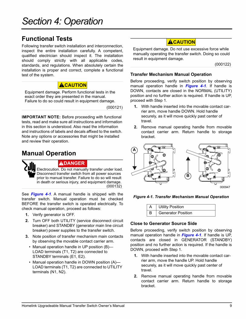
Transfer Mechanism Manual Operation
Before proceeding, verify switch position by observingmanual operation handle in Figure 4-1. If handle isDOWN, contacts are closed in the NORMAL (UTILITY)position and no further action is required. If handle is UP,proceed with Step 1.
1. With handle inserted into the movable contact car-rier arm, move handle DOWN. Hold handle securely, as it will move quickly past center of travel.
2. Remove manual operating handle from movablecontact carrier arm. Return handle to storagebracket.
Figure 4-1. Transfer Mechanism Manual Operation
Close to Generator Source Side
Before proceeding, verify switch position by observingmanual operation handle in Figure 4-1. If handle is UP,contacts are closed in GENERATOR (STANDBY)position and no further action is required. If the handle isDOWN, proceed with Step 1.
1. With handle inserted into the movable contact car-rier arm, move the handle UP. Hold handle securely, as it will move quickly past center of travel.
2. Remove manual operating handle from movablecontact carrier arm. Return handle to storagebracket.
(000121)
CAUTIONEquipment damage. Perform functional tests in the exact order they are presented in the manual. Failure to do so could result in equipment damage.
(000132)
DANGERElectrocution. Do not manually transfer under load. Disconnect transfer switch from all power sources prior to manual transfer. Failure to do so will resultin death or serious injury, and equipment damage.
A Utility Position
B Generator Position
(000122)
CAUTIONEquipment damage. Do not use excessive force while manually operating the transfer switch. Doing so could result in equipment damage.
000947
A
B
Homelink Upgradeable Manual Transfer Switch Owner’s Manual 9
Operation
Return to Utility Source Side
1. Manually actuate switch by moving manual operat-ing handle DOWN.
2. Remove manual operating handle from movablecontact carrier arm. Return handle to storagebracket.
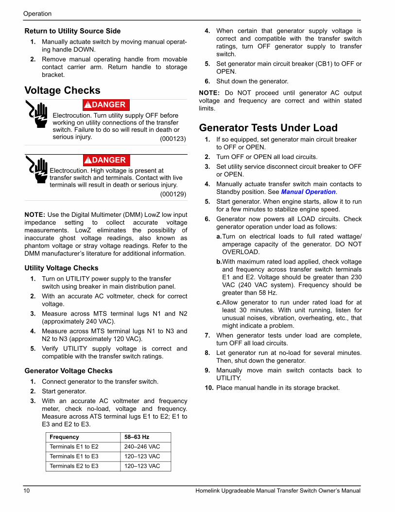
Voltage Checks
NOTE: Use the Digital Multimeter (DMM) LowZ low inputimpedance setting to collect accurate voltagemeasurements. LowZ eliminates the possibility ofinaccurate ghost voltage readings, also known asphantom voltage or stray voltage readings. Refer to theDMM manufacturer’s literature for additional information.
Utility Voltage Checks
1. Turn on UTILITY power supply to the transfer switch using breaker in main distribution panel.
2. With an accurate AC voltmeter, check for correctvoltage.
3. Measure across MTS terminal lugs N1 and N2(approximately 240 VAC).
4. Measure across MTS terminal lugs N1 to N3 andN2 to N3 (approximately 120 VAC).
5. Verify UTILITY supply voltage is correct andcompatible with the transfer switch ratings.
Generator Voltage Checks
1. Connect generator to the transfer switch.
2. Start generator.
3. With an accurate AC voltmeter and frequencymeter, check no-load, voltage and frequency.Measure across ATS terminal lugs E1 to E2; E1 toE3 and E2 to E3.
4. When certain that generator supply voltage iscorrect and compatible with the transfer switchratings, turn OFF generator supply to transferswitch.
5. Set generator main circuit breaker (CB1) to OFF orOPEN.
6. Shut down the generator.
NOTE: Do NOT proceed until generator AC outputvoltage and frequency are correct and within statedlimits.
Generator Tests Under Load1. If so equipped, set generator main circuit breaker
to OFF or OPEN.
2. Turn OFF or OPEN all load circuits.
3. Set utility service disconnect circuit breaker to OFFor OPEN.
4. Manually actuate transfer switch main contacts toStandby position. See Manual Operation.
5. Start generator. When engine starts, allow it to runfor a few minutes to stabilize engine speed.
6. Generator now powers all LOAD circuits. Checkgenerator operation under load as follows:
a.Turn on electrical loads to full rated wattage/amperage capacity of the generator. DO NOTOVERLOAD.
b.With maximum rated load applied, check voltageand frequency across transfer switch terminalsE1 and E2. Voltage should be greater than 230VAC (240 VAC system). Frequency should begreater than 58 Hz.
c.Allow generator to run under rated load for atleast 30 minutes. With unit running, listen forunusual noises, vibration, overheating, etc., thatmight indicate a problem.
7. When generator tests under load are complete,turn OFF all load circuits.
8. Let generator run at no-load for several minutes.Then, shut down the generator.
9. Manually move main switch contacts back toUTILITY.
10. Place manual handle in its storage bracket.
Frequency 58–63 Hz
Terminals E1 to E2 240–246 VAC
Terminals E1 to E3 120–123 VAC
Terminals E2 to E3 120–123 VAC
(000123)
DANGERElectrocution. Turn utility supply OFF before working on utility connections of the transfer switch. Failure to do so will result in death or serious injury.
(000129)
DANGERElectrocution. High voltage is present at transfer switch and terminals. Contact with live terminals will result in death or serious injury.
10 Homelink Upgradeable Manual Transfer Switch Owner’s Manual
Operation
Checking Electric Operation (Portable Generator Only)To check the system for proper electrical operation,proceed as follows:
1. Verify generator is OFF.
2. Connect the electrical harness six position quickconnector (from the lights and rocker switch of thefront panel) to transfer switch main harness.
3. See Figure 3-2. Install transfer switch front coverwith four (4) screws provided.
4. Turn ON utility power supply to the transfer switch,using the means provided (such as utility main linecircuit breaker). The Utility Light will illuminate onlyif the transfer switch is in the Generator position,and utility voltage is present.
5. Press rocker switch to select UTILITY. (Thetransfer switch will not operate without utilityvoltage present.) The Utility Light is now off and innormal operating condition; utility voltage ispresent and transfer switch is in normal utilitymode. Any loads will be energized via the powerpanel of the transfer switch.
6. Verify generator Neutral and Ground areconnected on the generator. The generator shouldbe properly tied to earth ground according to localregulations.
7. Connect generator to the PIB using the GeneracPortable Power Cord.
8. Turn generator ON. Amber indicator light forGenerator Power will illuminate on the front panelof the transfer switch any time generator voltage isavailable. Generator is now electrically isolatedfrom any electrical connections beyond the transferswitch.
9. Press rocker switch to select GENERATORPOWER. Utility light will illuminate to indicate utilityvoltage is available for transfer back to the utility.Generator light remains lit to indicate the presenceof generator voltage. All loads through the transferswitch panel are now being supplied by thegenerator.
10. Turn OFF utility power supply to the transferswitch, using the means provided (such as utilitymain line circuit breaker). Utility light will no longerbe illuminated, as utility voltage is no longerpresent.
11. Confirm any loads being supplied by the transferswitch panel are energized by the generator.
12. Turn ON utility power supply to the transfer switch,using the means provided (such as utility main linecircuit breaker). The Utility light will againilluminate.
13. Press rocker switch to select UTILITY. Utility lightwill turn off. Transfer switch is now in normaloperating mode. All loads from the transfer switchpanel are provided by the utility.
14. Let generator run at no load for several minutes.Then, shut down the generator. Generator powerlight on the transfer switch will turn off.
15. Disconnect generator portable power cord.
16. Store generator as recommended by themanufacturer.
17. Transfer switch testing is complete and ready foruse.
NOTE: Transfer switch requires 240V electric power tooperate with the rocker switch. Transfer switch will nottransfer to utility mode if Utility light is not illuminated priorto pressing rocker switch. Transfer switch will not transferto generator mode if the Generator light is notilluminated. This safeguards against accidental transferto the generator if generator power is not present.
Checking Automatic Operation(Automatic HSB Generator Only)To check the system for proper automatic operation,proceed as follows:
1. Verify generator is OFF.
2. Verify switch is de-energized.
3. Manually operate transfer switch twice to properlyset mechanism toggle after installation.
4. Install transfer switch front cover.
5. Turn utility power supply to transfer switch ON,using utility main line circuit breaker.
6. Set generator main circuit breaker to ON.
7. On generator panel, select AUTO. System is nowready for automatic operation.
8. Turn utility power supply to the transfer switch OFF.
With generator ready for automatic operation, engineshould crank and start when utility source power is turnedOFF after a ten second delay (factory default setting).After starting, transfer switch should connect load circuitsto the standby side after the engine warm-up delay. Letthe system operate through its entire automaticsequence of operation.
With generator running and loads powered by generatorAC output, turn ON utility power supply to transfer switch.The following should occur:
• After approximately 15 seconds, the switch shouldtransfer loads back to the utility power source.
• Approximately one minute after re-transfer, theengine should shut down.
With generator in AUTOMATIC mode, the system is nowset for fully automatic operation.
Homelink Upgradeable Manual Transfer Switch Owner’s Manual 11
Operation
Installation Summary1. Verify installation has been properly performed as
outlined by the manufacturer and meets all applica-ble laws and codes.
2. Verify proper operation of the system as outlined inthe appropriate installation and owner’s manuals.
3. Educate end user on proper operation,maintenance and service call procedures.
Shutting Generator Down WhileUnder Load(Automatic HSB Generator Only)To turn the generator OFF during utility outages toperform maintenance, or conserve fuel, follow theseimportant steps:
To turn the generator OFF (while running in AUTO andOnline):
1. Turn main utility disconnect OFF.
2. Turn main line circuit breaker (MLCB) on generatorto OFF (OPEN).
3. Allow generator to run and cool down forapproximately one minute.
4. Turn generator OFF.
NOTE: If turning the unit off longer than 24 hours,remove F1 fuse from generator controller.
To turn the generator ON:
1. Install F1 fuse if necessary.
2. Put the generator back into AUTO and allow tostart and warm up for a few minutes.
3. Set MLCB on the generator to ON.
The system will now be operating in automatic mode.The main utility disconnect can be turned ON (CLOSED).
NOTE: To shut the unit off, this complete process mustbe repeated.
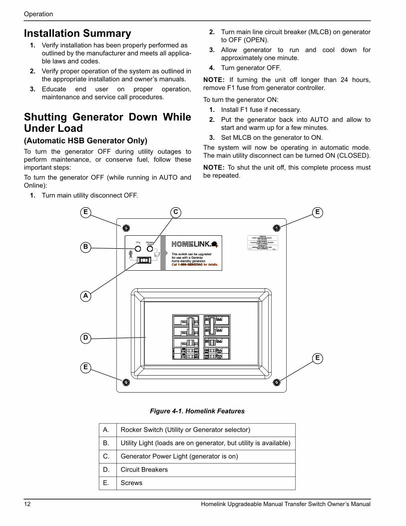
Figure 4-1. Homelink Features
A. Rocker Switch (Utility or Generator selector)
B. Utility Light (loads are on generator, but utility is available)
C. Generator Power Light (generator is on)
D. Circuit Breakers
E. Screws
This switch can be upgraded
for use with a Generac
home standby generator.
Call 1-888-GENERAC for details.
This switch can be upgraded
for use with a Generac
home standby generator.
Call 1-888-GENERAC for details.
This switch can be upgraded
for use with a Generac
home standby generator.
Call 1-888-GENERAC for details.
This switch can be upgraded
for use with a Generac
home standby generator.
Call 1-888-GENERAC for details.
This switch can be upgraded
for use with a Generac
home standby generator.
Call 1-888-GENERAC for details.
This switch can be upgraded
for use with a Generac
home standby generator.
Call 1-888-GENERAC for details.
This switch can be upgraded
for use with a Generac
home standby generator.
Call 1-888-GENERAC for details.
This switch can be upgraded
for use with a Generac
home standby generator.
Call 1-888-GENERAC for details.
This switch can be upgraded
for use with a Generac
home standby generator.
Call 1-888-GENERAC for details.
This switch can be upgraded
for use with a Generac
home standby generator.
Call 1-888-GENERAC for details.
WARNING- MORE THAN ONE LIVE CIRCUIT
AVERTISSEMENT- PLUS D'UN CIRCUIT SOUS TENSION
-MAS DE UN CIRCUITO VIVOADVERTENCIA
- VEA DIAGRAMA
- VOIR LE SCHEMA
- SEE DIAGRAM
0G3274-A
E
EC
E
D
A
B
E
12 Homelink Upgradeable Manual Transfer Switch Owner’s Manual
Drawings and Diagrams
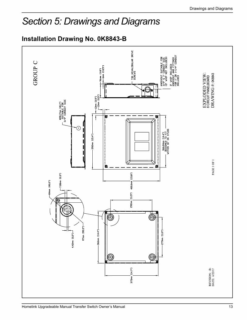
Section 5: Drawings and Diagrams
Installation Drawing No. 0K8843-B
Homelink Upgradeable Manual Transfer Switch Owner’s Manual 13

Drawings and Diagrams
Interconnection Drawing No. 0K8845-A (Manual Transfer Connections)
100A
OR
200A
SERV
ICE
HOUS
E M
AIN
CIRC
UIT
BREA
KER
50A
2-PO
LE
8 CI
RCUI
T TR
ANSF
ER S
WIT
CH
NEUT
N2N1
E1E2
GNDGND
NEUT
POW
ER IN
LET
BOX
* NO
TE:
WHE
N UT
ILIZ
ED IN
THI
S AP
PLIC
ATIO
NA
GRO
UNDI
NG E
LECT
RODE
MAY
BE
REQ
UIRE
D BY
LO
CAL
CODE
TO
BE
CONN
ECTE
D TO
THE
GEN
ERAT
OR.
14 Homelink Upgradeable Manual Transfer Switch Owner’s Manual

Drawings and Diagrams
Interconnection Drawing No. 0K8844-C (Automatic Transfer Connections)
100A
OR
200
A
SE
RV
ICE
HO
US
E M
AIN
CIR
CU
IT B
RE
AK
ER
50A
2-P
OLE
T1 N2 N1
23 194
E2E1
GN
D
T1N
2N
123
194
E2
E1
N1
N2
GE
NE
RAT
OR
CU
STO
ME
R
CO
NN
EC
TIO
N
8 C
IRC
UIT
TR
AN
SFE
R S
WIT
CH
CU
STO
ME
R S
UP
PLI
ED
JUN
CTI
ON
BO
X
Homelink Upgradeable Manual Transfer Switch Owner’s Manual 15

Drawings and Diagrams
This page intentionally left blank.
16 Homelink Upgradeable Manual Transfer Switch Owner’s Manual

Drawings and Diagrams
This page intentionally left blank.
Homelink Upgradeable Manual Transfer Switch Owner’s Manual 17

Drawings and Diagrams
This page intentionally left blank.
18 Homelink Upgradeable Manual Transfer Switch Owner’s Manual


Part No. 10000012180 Rev. A 07/21/17©2017 Generac Power Systems, Inc.All rights reservedSpecifications are subject to change without notice.No reproduction allowed in any form without prior written consent from Generac Power Systems, Inc.
Generac Power Systems, Inc.S45 W29290 Hwy. 59Waukesha, WI 53189
1-888-GENERAC (1-888-436-3722)www.generac.com