Embed Size (px)
Citation preview
OWNERS AND SERVICE MANUALCOPYRIGHT 2000, INNOVATIVE CONCEPTS IN ENTERTAINMENT INC.
MANUFACTURED UNDER LICENSE FROM JUPITER GAMES
10123 MAIN STREET, CLARENCE, NY 14031SERVICE 1-716-759-0360 FAX 1-716-759-0084 E-MAIL [email protected]
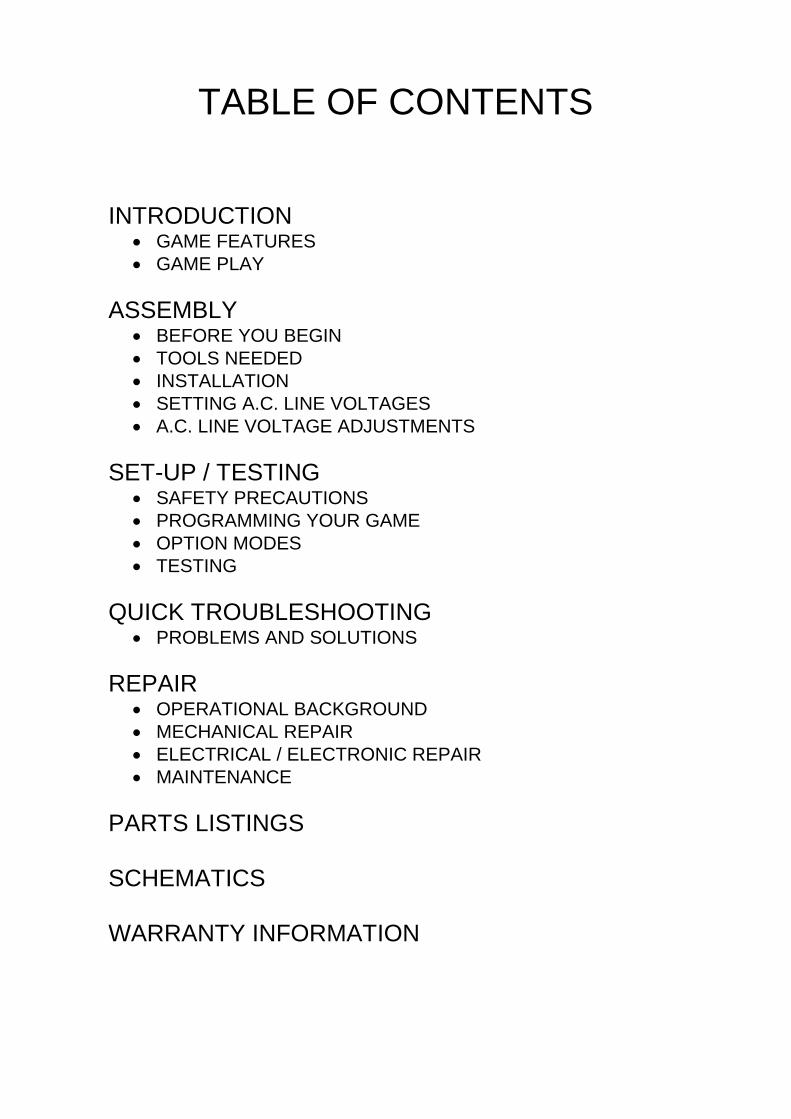
TABLE OF CONTENTS
INTRODUCTION� GAME FEATURES� GAME PLAY
ASSEMBLY� BEFORE YOU BEGIN� TOOLS NEEDED� INSTALLATION� SETTING A.C. LINE VOLTAGES� A.C. LINE VOLTAGE ADJUSTMENTS
SET-UP / TESTING� SAFETY PRECAUTIONS� PROGRAMMING YOUR GAME� OPTION MODES� TESTING
QUICK TROUBLESHOOTING� PROBLEMS AND SOLUTIONS
REPAIR� OPERATIONAL BACKGROUND� MECHANICAL REPAIR� ELECTRICAL / ELECTRONIC REPAIR� MAINTENANCE
PARTS LISTINGS
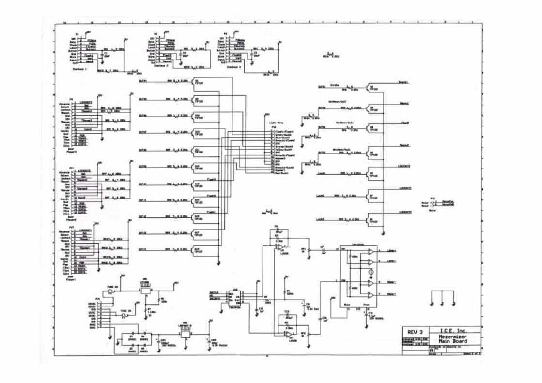
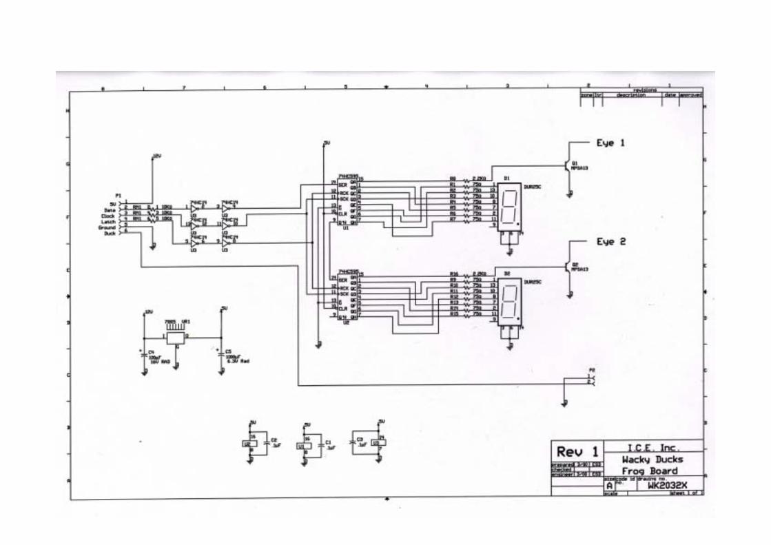
SCHEMATICS
WARRANTY INFORMATION
INTRODUCTION
GAME FEATURESThank you for your purchase of the new WACKYDUCKS� redemption game from I.C.E.
Through an exclusive agreement with JUPITERGAMES, I.C.E. is able to bring you an innovativeproduct with all of the features and reliabilityyou've come to expect in our games.
The game is constructed of a quality 7 ply MDOplywood cabinet. The cabinet is then sealed,painted and decaled using laminated graphicsthat resist most common cleaning agents. Allmetal parts are powder coated for maximumbeauty and durability.
The game uses creative lighting techniques todraw game players to it and to enhance gameenjoyment. Long lasting rope light is used for themarquee that is mounted behind a multi-colorgraphics panel to create an attractive rainbowpattern. Flashing ducks and super bright signgrade florescent lighting round out the lightingpackage.
A unique cartoon like Punching Glove on ascissors mechanism gives the game a fun wayfor Kids to play the game. The mechanism hasbeen extensively tested for durability andreliability. The solenoid coil that drives themechanism is fan cooled and thermallyprotected. The coil is also operated on lowvoltage D.C. power.
The game electronics are at the same time hightech, yet all drive components are chosen fortheir long history of reliability. Surface mountcomponents and programmable logic arrays keepthe board size to a minimum and the reliability tothe maximum.
A high quality digital audio amplifier is used to re-create some of the funniest sounds you'll everhear in a game. A variety of funny duck soundswill keep you laughing for hours on end.
The ducks move along a belt that is powered bya heavy-duty 12-volt gear motor. This motor hasbeen chosen for its long lasting and cool runningcapabilities. It has a full-length drive shaft forgreater reliability.
All electronics are fully operator adjustable andare adjusted via convenient programming buttonslocated just inside the coin door. The gameallows the operator to choose a timed game or arandom hit game depending on the operators'location. (Please see the Game Play sectionbelow and the programming section for furtherinformation).
GAME PLAY
The game can be set up to be played in twodifferent ways. Both ways are described below.
TIMED GAME
The player inserts their money into the game tobegin. Behind the row of ducks are Frog displaysthat have a "time" indicator on them. Once theplayer tries to hit his first duck, the count downtimer will begin. (The timer will also begin if theplayer does nothing for ten seconds or more).Once the timer begins, the player needs to hit asmany ducks as possible before time runs out.The player will be awarded tickets based on howmany ducks have been knocked down. Theplayer may also receive "mercy" tickets if theywere unable to hit any ducks.
ONE HIT GAME
In this version of the game, the player inserts hismoney to start the game. Then the Frog displaywill show a random number of "Tickets" that canbe won. This number will constantly continue tochange during game play. The player can hit thepunch button multiple times, however the game

INTRODUCTION
ends once the player hits a duck. The player thenwins the tickets that were displayed at the time ofthe hit.
NOTE: This game is generally set up as a "OneHit" game. The operator can however set thegame up for a different predetermined number ofhits.
ASSEMBLYBEFORE YOU BEGIN
WARNING: WHEN INSTALLING THIS GAME, A3 PRONG GROUNDED A.C. RECEPTICLEMUST BE USED. FAILURE TO DO SO COULDRESULT IN INJURY TO YOURSELF OROTHERS. FAILURE TO USE A GROUNDEDRECEPTICLE COULD ALSO CAUSEIMPROPER GAME OPERATION, OR DAMAGETO THE ELECTRONICS
DO NOT DEFEAT OR REMOVE THEGROUNDING PRONG ON THE POWER CORDFOR THE SAME REASON AS GIVEN ABOVE.USING AN IMPROPERLY GROUNDED GAMECOULD VOID YOUR WARRANTY.
HAVE A QUALIFIED ELECTRICIAN CHECKYOU’RE A.C. RECEPTICLE TO BE SURE THEGROUND IS FUNCTIONING PROPERLY.
TOOLS NEEDEDTo assemble your game you will need a 7/16"socket or box wrench.
Note: For normal game servicing you will needtwo different size Allen wrenches which areprovided.
INSTALLATION1. Remove the cardboard box from the pallet.
2. Cut banding that holds the game to the pallet.
NOTE: BE SURE TO STAND TO THESIDE WHEN CUTTING THE BANDS, ASTHEY ARE UNDER PRESSURE, ANDCOULD SPRING OUT CAUSINGINJURY.
3. Remove all of the shrink-wrap and packaging from the game and marquee.
4. Find the location that the game will be placed in and move into rough position.
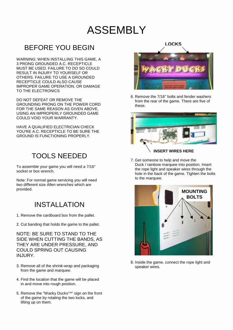
5. Remove the "Wacky Ducks�" sign on the front of the game by rotating the two locks, and lifting up on them.
6. Remove the 7/16" bolts and fender washers from the rear of the game. There are five of these.
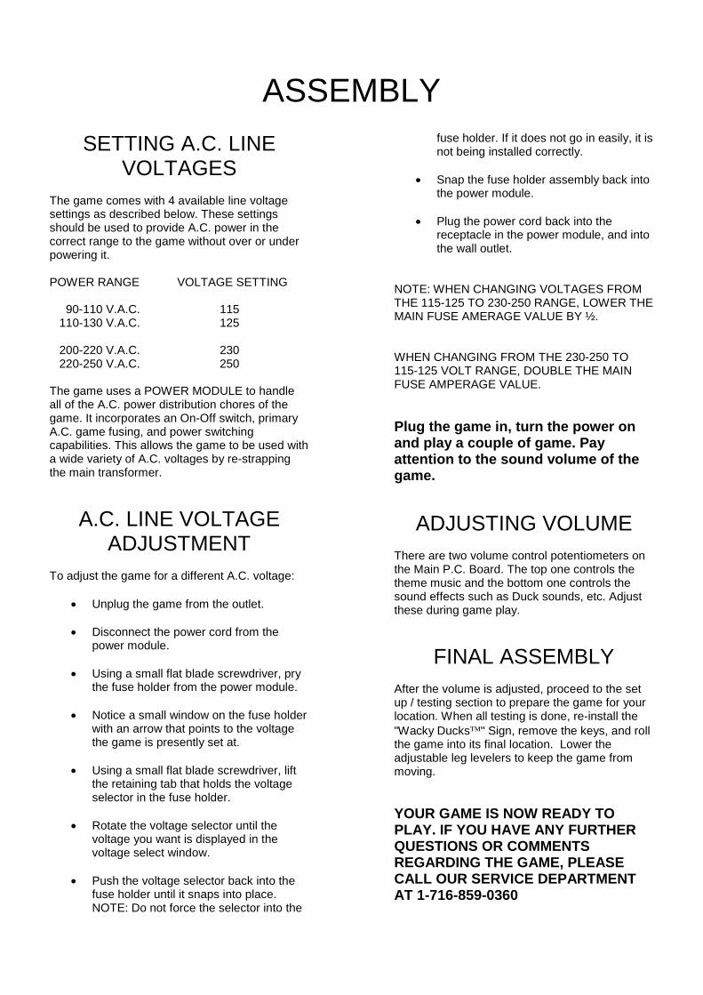
INSERT WIRES HERE
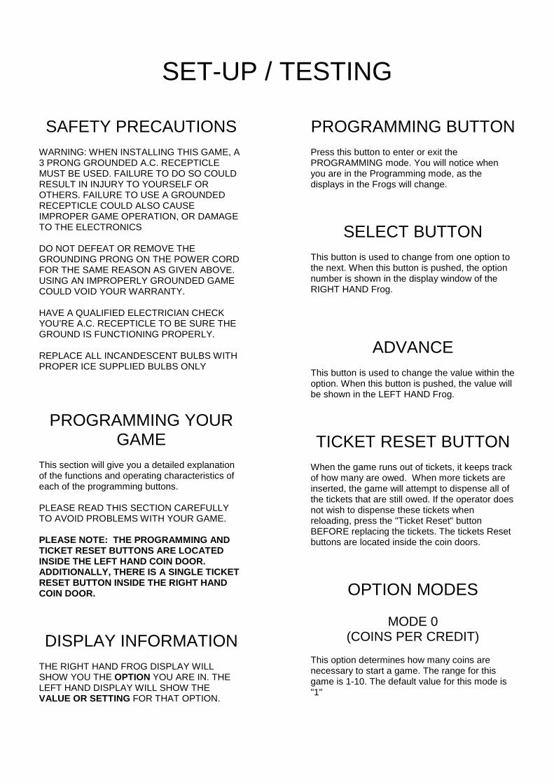
7. Get someone to help and move the Duck / rainbow marquee into position. Insert the rope light and speaker wires through the hole in the back of the game. Tighten the bolts to the marquee.
8. Inside the game, connect the rope light and speaker wires.
LOCKS
MOUNTINGBOLTS
ASSEMBLYSETTING A.C. LINE
VOLTAGESThe game comes with 4 available line voltagesettings as described below. These settingsshould be used to provide A.C. power in thecorrect range to the game without over or underpowering it.
POWER RANGE VOLTAGE SETTING
90-110 V.A.C. 115 110-130 V.A.C. 125
200-220 V.A.C. 230 220-250 V.A.C. 250
The game uses a POWER MODULE to handleall of the A.C. power distribution chores of thegame. It incorporates an On-Off switch, primaryA.C. game fusing, and power switchingcapabilities. This allows the game to be used witha wide variety of A.C. voltages by re-strappingthe main transformer.
A.C. LINE VOLTAGEADJUSTMENT
To adjust the game for a different A.C. voltage:
� Unplug the game from the outlet.
� Disconnect the power cord from thepower module.
� Using a small flat blade screwdriver, prythe fuse holder from the power module.
� Notice a small window on the fuse holderwith an arrow that points to the voltagethe game is presently set at.
� Using a small flat blade screwdriver, liftthe retaining tab that holds the voltageselector in the fuse holder.
� Rotate the voltage selector until thevoltage you want is displayed in thevoltage select window.
� Push the voltage selector back into thefuse holder until it snaps into place.NOTE: Do not force the selector into the
fuse holder. If it does not go in easily, it isnot being installed correctly.
� Snap the fuse holder assembly back intothe power module.
� Plug the power cord back into thereceptacle in the power module, and intothe wall outlet.
NOTE: WHEN CHANGING VOLTAGES FROMTHE 115-125 TO 230-250 RANGE, LOWER THEMAIN FUSE AMERAGE VALUE BY ½.
WHEN CHANGING FROM THE 230-250 TO115-125 VOLT RANGE, DOUBLE THE MAINFUSE AMPERAGE VALUE.
Plug the game in, turn the power onand play a couple of game. Payattention to the sound volume of thegame.
ADJUSTING VOLUMEThere are two volume control potentiometers onthe Main P.C. Board. The top one controls thetheme music and the bottom one controls thesound effects such as Duck sounds, etc. Adjustthese during game play.
FINAL ASSEMBLYAfter the volume is adjusted, proceed to the setup / testing section to prepare the game for yourlocation. When all testing is done, re-install the"Wacky Ducks�" Sign, remove the keys, and rollthe game into its final location. Lower theadjustable leg levelers to keep the game frommoving.
YOUR GAME IS NOW READY TOPLAY. IF YOU HAVE ANY FURTHERQUESTIONS OR COMMENTSREGARDING THE GAME, PLEASECALL OUR SERVICE DEPARTMENTAT 1-716-859-0360
SET-UP / TESTING
SAFETY PRECAUTIONSWARNING: WHEN INSTALLING THIS GAME, A3 PRONG GROUNDED A.C. RECEPTICLEMUST BE USED. FAILURE TO DO SO COULDRESULT IN INJURY TO YOURSELF OROTHERS. FAILURE TO USE A GROUNDEDRECEPTICLE COULD ALSO CAUSEIMPROPER GAME OPERATION, OR DAMAGETO THE ELECTRONICS
DO NOT DEFEAT OR REMOVE THEGROUNDING PRONG ON THE POWER CORDFOR THE SAME REASON AS GIVEN ABOVE.USING AN IMPROPERLY GROUNDED GAMECOULD VOID YOUR WARRANTY.
HAVE A QUALIFIED ELECTRICIAN CHECKYOU’RE A.C. RECEPTICLE TO BE SURE THEGROUND IS FUNCTIONING PROPERLY.
REPLACE ALL INCANDESCENT BULBS WITHPROPER ICE SUPPLIED BULBS ONLY
PROGRAMMING YOURGAME
This section will give you a detailed explanationof the functions and operating characteristics ofeach of the programming buttons.
PLEASE READ THIS SECTION CAREFULLYTO AVOID PROBLEMS WITH YOUR GAME.
PLEASE NOTE: THE PROGRAMMING ANDTICKET RESET BUTTONS ARE LOCATEDINSIDE THE LEFT HAND COIN DOOR.ADDITIONALLY, THERE IS A SINGLE TICKETRESET BUTTON INSIDE THE RIGHT HANDCOIN DOOR.
DISPLAY INFORMATIONTHE RIGHT HAND FROG DISPLAY WILLSHOW YOU THE OPTION YOU ARE IN. THELEFT HAND DISPLAY WILL SHOW THEVALUE OR SETTING FOR THAT OPTION.
PROGRAMMING BUTTONPress this button to enter or exit thePROGRAMMING mode. You will notice whenyou are in the Programming mode, as thedisplays in the Frogs will change.
SELECT BUTTONThis button is used to change from one option tothe next. When this button is pushed, the optionnumber is shown in the display window of theRIGHT HAND Frog.
ADVANCEThis button is used to change the value within theoption. When this button is pushed, the value willbe shown in the LEFT HAND Frog.
TICKET RESET BUTTONWhen the game runs out of tickets, it keeps trackof how many are owed. When more tickets areinserted, the game will attempt to dispense all ofthe tickets that are still owed. If the operator doesnot wish to dispense these tickets whenreloading, press the "Ticket Reset" buttonBEFORE replacing the tickets. The tickets Resetbuttons are located inside the coin doors.
OPTION MODES
MODE 0(COINS PER CREDIT)
This option determines how many coins arenecessary to start a game. The range for thisgame is 1-10. The default value for this mode is"1"
SET-UP / TESTING
MODE 1(GAME LENGTH)
This mode determines how long the game lastsin SECONDS. The range for this value is 0-30.The default value for this game is "10"
SETTING A "0" FOR THIS MODE WILL PUTTHE GAME INTO THE "RANDOM TICKET"MODE.
MODE 2(COIN OR CREDIT COUNTER)
This mode determines if the coin counter willcount coins or credits. (Example: If it takes 3coins to start a game, then 3 coins would equal 1credit). Setting a "0" equals coins. Setting a "1"equals credits. The default value for this option is"0".
MODE 3(TIME BETWEEN HITS)
This mode determines how long the game willmake the player wait between hits of thepunching glove. The number shown X 100milliseconds equals the actual time. (Example: 10X 100 milliseconds equal 1 second). The rangefor this option is 10-50 (1 to 5 seconds). Thedefault value for this option is "10"
MODE 4(DUCKS PER XX TICKET
DISPENSE)This option determines how many ducks must beknocked down each time XX tickets can bedispensed. (See OPTION 6 for value of XX) Therange for this option is 1-9. The default value forthis option is "1".
FOR EXAMPLE, if the value set in OPTION 4 is"2" and the value set in OPTION 5 is "3", thegame would dispense 3 tickets for every 2 ducksknocked down.
MODE 5(VALUE OF XX)
This option determines the number of tickets todispense each time a dispense order is given byOPTION MODE 4. The range for this option is 1-9. The default value for this option is "1".
MODE 6(JUST FOR PLAYING TICKETS)
This mode determines the amount of "Mercy"tickets paid to the customer ion the event thatthey do not win any tickets during normal gameplay. The range for this option is 0-99. Thedefault value for this option is "3"
NOTE: THIS OPTION FUNCTIONS IN THETIMED GAME MODE ONLY.
MODE 7(ATTRACT TIME)
This mode determines the period of time betweenattract modes. The numbers in this optionrepresent minutes. The range for this option is 0-90. Setting a "0" equals turning the attract modeOFF. The default value for this option is "3
MODE 8(ATTRACT MODE TYPE)
This option determines which type of attractmode is set.
0= Mode Disabled1= Audio only2= Motion only3= both motion and audio
The default value for this option is "3"
SET-UP / TESTING
MODE 9(FACTORY RESET)
This mode has the capability to reset all optionsto the factory default values. The range for thisoption is 0-1. Setting a "1" will reset all values.The default value for this option is "0" (no reset)
NOTE: THE GAME CAN ALSO BE RESET TOFACTORY DEFAULT VALUES BY TURNINGTHE GAME OFF, REMOVING THE BATTERYFROM THE MAIN P.C. BOARD. , WAIT A FEWMINUTES THEN TURN THE GAME BACK ON.
THE ABOVE PROCEEDURE IS ALSOVALUABLE IF FOR SOME REASON THE GAMEELECTRONICS WERE TO LOCK OR FREEZEUP.
GAME TESTINGAfter you have completed the set-up of yourgame, INSTALL TICKETS into the game, andplay a few games to make sure everything isworking properly. Check the following:
� Check the ticket dispenser to be sure theproper amount of tickets is given.
� Check to be sure the duck belt is trackingproperly. If not, check the mechanicalrepair section for adjustment procedures.
� Be sure all external fasteners like thoseof the cover glass and puncher housingsare installed and tight.
SET-UP / TESTING
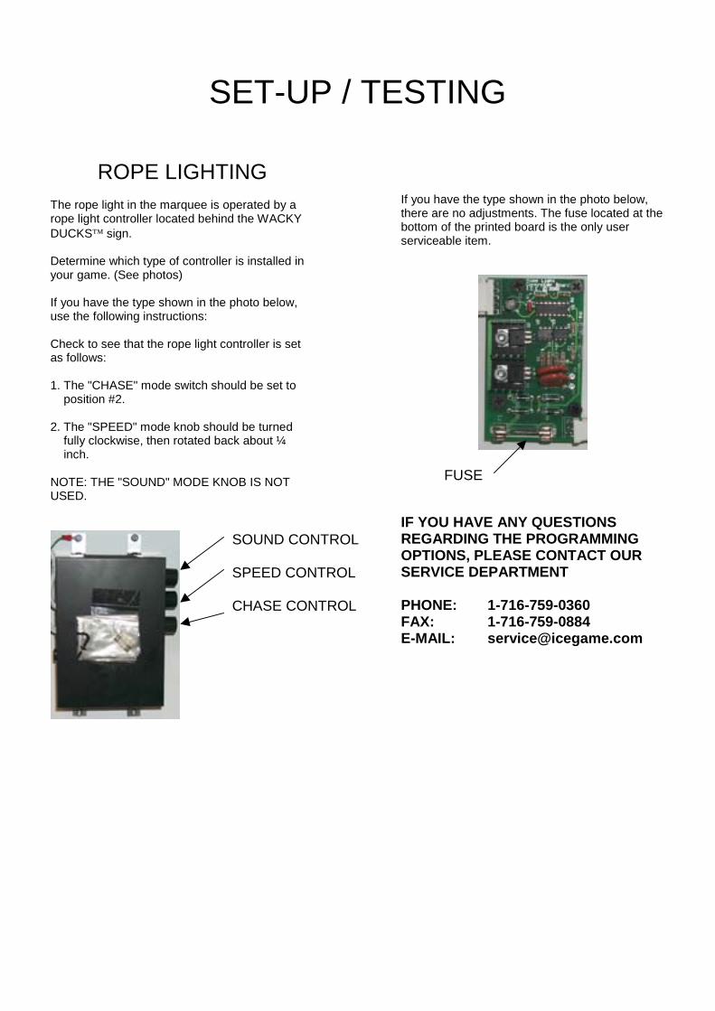
ROPE LIGHTINGThe rope light in the marquee is operated by arope light controller located behind the WACKYDUCKS� sign.
Determine which type of controller is installed inyour game. (See photos)
If you have the type shown in the photo below,use the following instructions:
Check to see that the rope light controller is setas follows:
1. The "CHASE" mode switch should be set to position #2.
2. The "SPEED" mode knob should be turned fully clockwise, then rotated back about ¼ inch.
NOTE: THE "SOUND" MODE KNOB IS NOTUSED.
If you have the type shown in the photo below,there are no adjustments. The fuse located at thebottom of the printed board is the only userserviceable item.
FUSE
IF YOU HAVE ANY QUESTIONSREGARDING THE PROGRAMMINGOPTIONS, PLEASE CONTACT OURSERVICE DEPARTMENT
PHONE: 1-716-759-0360FAX: 1-716-759-0884E-MAIL: [email protected]
SOUND CONTROL
SPEED CONTROL
CHASE CONTROL
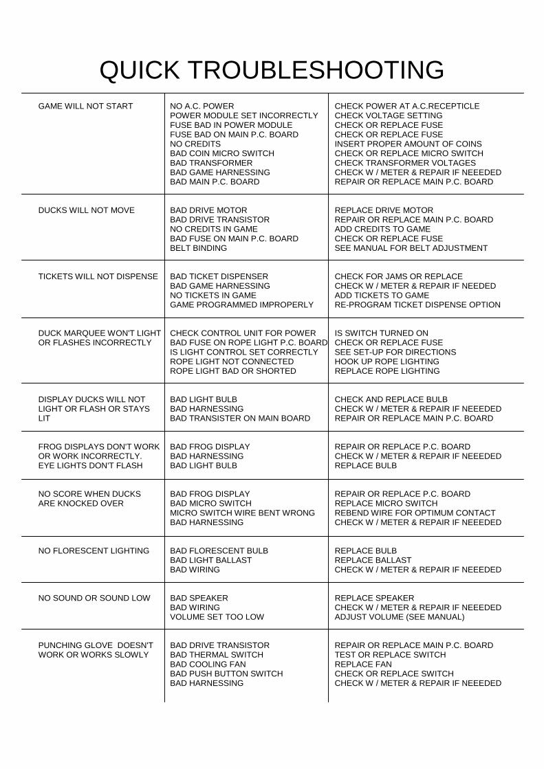
QUICK TROUBLESHOOTINGGAME WILL NOT START NO A.C. POWER CHECK POWER AT A.C.RECEPTICLE
POWER MODULE SET INCORRECTLY CHECK VOLTAGE SETTINGFUSE BAD IN POWER MODULE CHECK OR REPLACE FUSEFUSE BAD ON MAIN P.C. BOARD CHECK OR REPLACE FUSENO CREDITS INSERT PROPER AMOUNT OF COINSBAD COIN MICRO SWITCH CHECK OR REPLACE MICRO SWITCHBAD TRANSFORMER CHECK TRANSFORMER VOLTAGESBAD GAME HARNESSING CHECK W / METER & REPAIR IF NEEEDEDBAD MAIN P.C. BOARD REPAIR OR REPLACE MAIN P.C. BOARD
DUCKS WILL NOT MOVE BAD DRIVE MOTOR REPLACE DRIVE MOTORBAD DRIVE TRANSISTOR REPAIR OR REPLACE MAIN P.C. BOARDNO CREDITS IN GAME ADD CREDITS TO GAMEBAD FUSE ON MAIN P.C. BOARD CHECK OR REPLACE FUSEBELT BINDING SEE MANUAL FOR BELT ADJUSTMENT
TICKETS WILL NOT DISPENSE BAD TICKET DISPENSER CHECK FOR JAMS OR REPLACEBAD GAME HARNESSING CHECK W / METER & REPAIR IF NEEDEDNO TICKETS IN GAME ADD TICKETS TO GAMEGAME PROGRAMMED IMPROPERLY RE-PROGRAM TICKET DISPENSE OPTION
DUCK MARQUEE WON'T LIGHT CHECK CONTROL UNIT FOR POWER IS SWITCH TURNED ONOR FLASHES INCORRECTLY BAD FUSE ON ROPE LIGHT P.C. BOARD CHECK OR REPLACE FUSE
IS LIGHT CONTROL SET CORRECTLY SEE SET-UP FOR DIRECTIONSROPE LIGHT NOT CONNECTED HOOK UP ROPE LIGHTINGROPE LIGHT BAD OR SHORTED REPLACE ROPE LIGHTING
DISPLAY DUCKS WILL NOT BAD LIGHT BULB CHECK AND REPLACE BULBLIGHT OR FLASH OR STAYS BAD HARNESSING CHECK W / METER & REPAIR IF NEEEDEDLIT BAD TRANSISTER ON MAIN BOARD REPAIR OR REPLACE MAIN P.C. BOARD
FROG DISPLAYS DON'T WORK BAD FROG DISPLAY REPAIR OR REPLACE P.C. BOARDOR WORK INCORRECTLY. BAD HARNESSING CHECK W / METER & REPAIR IF NEEEDEDEYE LIGHTS DON'T FLASH BAD LIGHT BULB REPLACE BULB
NO SCORE WHEN DUCKS BAD FROG DISPLAY REPAIR OR REPLACE P.C. BOARDARE KNOCKED OVER BAD MICRO SWITCH REPLACE MICRO SWITCH
MICRO SWITCH WIRE BENT WRONG REBEND WIRE FOR OPTIMUM CONTACTBAD HARNESSING CHECK W / METER & REPAIR IF NEEEDED
NO FLORESCENT LIGHTING BAD FLORESCENT BULB REPLACE BULBBAD LIGHT BALLAST REPLACE BALLASTBAD WIRING CHECK W / METER & REPAIR IF NEEEDED
NO SOUND OR SOUND LOW BAD SPEAKER REPLACE SPEAKERBAD WIRING CHECK W / METER & REPAIR IF NEEEDEDVOLUME SET TOO LOW ADJUST VOLUME (SEE MANUAL)
PUNCHING GLOVE DOESN'T BAD DRIVE TRANSISTOR REPAIR OR REPLACE MAIN P.C. BOARDWORK OR WORKS SLOWLY BAD THERMAL SWITCH TEST OR REPLACE SWITCH
BAD COOLING FAN REPLACE FANBAD PUSH BUTTON SWITCH CHECK OR REPLACE SWITCHBAD HARNESSING CHECK W / METER & REPAIR IF NEEEDED
REPAIROPERATIONALBACKGROUND
The WACKY DUCKS� game has been designedto be as easy as possible to repair.
The duck belt can be easily adjusted while in thegame, yet can be removed easily from the gameif replacement should ever become necessary.
The punching mechanisms have been designedfor easy access by simply removing the accesscovers.
TROUBLESHOOTINGPHILOSOPHY
To find problems with the game, always firstcheck what should be obvious. See that thegame is plugged in, and that all of the fuses onthe game are good. This includes the fuse that islocated INSIDE the power module.
Next, check to see that all of the connectors arefirmly seated and that none of the wires havebeen pulled out of them.
When trying to find out if specific components arebad or not, try swapping them with componentsfrom another player station to see if the problemmoves with the component, or stays where itwas. This will help you to know if you have aproblem with a specific component, or maybe aproblem with either the wiring or the Main P.C.Board.
Use extreme caution when using probes orvoltmeters if the game is powered up. If doingcontinuity checks, it is important to disconnect theharnessing at both ends, as attached they mayyield erroneous results.
If a P.C. Board is suspected as the cause of aproblem, check to see that all of the componentson the board are firmly attached. Pay specialattention to any socketed devices.
If light bulbs are suspected, swap them with onethat is known to work to narrow the problemdown to either a bulb or P.C. Board.
MECHANICAL REPAIR
PUNCHING GLOVE ASSEMBLYOVERVIEW
The punching glove system is designed for highreliability and safety. The assembly can bedesigned with simplicity in mind, as the solenoidis driven for maximum pull in strength.
The solenoid is driven by approximately 35 DCvolts. This voltage may be higher or lowerdepending on your A.C. voltage at the wall.
The solenoid is fan cooled to allow for highervoltages that will in turn provide the higher pull instrength.
Since fan cooling is necessary under a highgame play mode, the solenoid is protected by abi-metal thermal switch that is strapped directly tothe solenoid bobbin. This switch assures that ifthe fan fails, the solenoid power will be shut downbefore the coil could be damaged.
The thermal switch is run "IN LINE" with thesolenoid power. This simple arrangement is veryreliable and easy to troubleshoot.
TESTING THE COILTESTING FOR POWER - Disconnect the coilfrom the connectors. Using a voltmeter, measurethat voltage is present during game play if thepunch button is pressed. There should be avoltage of 30+ volts D.C. If you do not see thismuch voltage, but do see some, your meter isprobably too slow to see the voltage, as it is onlyon for approximately 100 milliseconds. If youdon't see any voltage at all, the solenoid driverF.E.T. on the main P.C. Board could be bad. Itcould also be that the push button is not sendinga signal to the main P.C. Board.
If you see voltage to the coil, but the mechanismwon't fire, check that the thermal switch isworking correctly. When the thermal switch iscool, disconnect the wires from its leads and do acontinuity test across the switch terminals. Youshould see continuity. If you don't, the switchneeds to be replaced.
REPAIRIf you see that the thermal switch is good, checkto see that the coil and the diode on the coil aregood.
Disconnect the coil and unsolder 1 side of thediode. Do a resistance check to see that there isinfinite resistance in one direction. If there is noresistance in either direction the diode is bad. Ifthe diode is bad, there is also a chance that thedrive transistor and / or fuse could be bad aswell.
If the diode tests good, check to see theresistance of the coil. It should measureapproximately 3.8 ohms. This resistance will varysome depending on the temperature of the coil. Ifthe resistance is significantly more or less, thecoil should be replaced.
COIL REPLACEMENT
1. Remove the 2 bolts that hold thepunching mech cover in place.
2. Disconnect the micro switch assemblyfrom the push button and remove thecover.
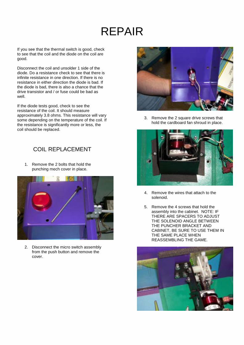
3. Remove the 2 square drive screws thathold the cardboard fan shroud in place.
4. Remove the wires that attach to thesolenoid.
5. Remove the 4 screws that hold theassembly into the cabinet. NOTE: IFTHERE ARE SPACERS TO ADJUSTTHE SOLENOID ANGLE BETWEENTHE PUNCHER BRACKET ANDCABINET, BE SURE TO USE THEM INTHE SAME PLACE WHENREASSEMBLING THE GAME.
REPAIR6. Remove the hex nuts that secure the 2
long shoulder bolts to the punchermounting bracket. Unscrew the twoshoulder bolts from the punchermounting bracket. The puncher assemblyshould now be able to be removed.
7. Remove the 2 screws that hold the coilretaining bracket to the puncher bracket.The solenoid may now be removed.
8. Assemble in the reverse order.
NOTE: WHEN RE-ASSEMBLING THEPUNCHER ASSEMBLY, BE SURE TO USELOCK-TITE ON THE SHOULDER BOLTTHREADS AND RETAINING NUTS.
DUCK BELT ASSEMBLYADJUSTMENT AND REPAIR
There are two different adjustments that shouldbe occasionally performed on the belt assembly.
The first is an adjustment to get the properamount of tension to the duck belt. This isimportant to prevent the ducks from hanging toolow on the bottom of the belt, and to help insureproper tracking.
The second type of adjustment is to set thetracking accurately to the center of the belt board.
NOTE: BOTH OF THE ABOVE ADJUSTMENTSARE NECESSARY WHEN THE BELT NOLONGER RUNS CENTERED ON THE BELTBOARD OR WHEN REPAIRS TO THE DUCKBELT ASSEMBLY ARE PERFORMED.
MOTOR REPAIR1. Turn off A.C power
2. Remove cover glass by removing the 4Allen screws that hold the glass retainer.
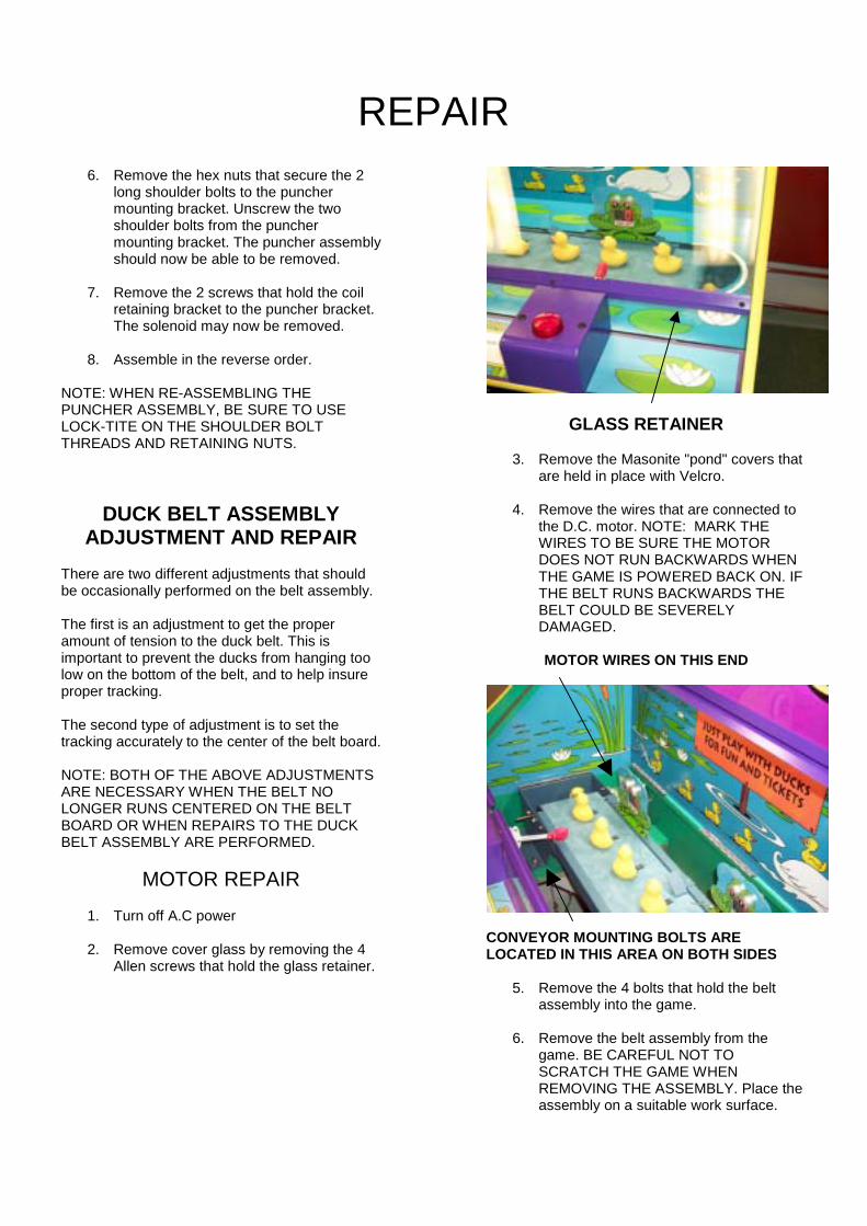
GLASS RETAINER
3. Remove the Masonite "pond" covers thatare held in place with Velcro.
4. Remove the wires that are connected tothe D.C. motor. NOTE: MARK THEWIRES TO BE SURE THE MOTORDOES NOT RUN BACKWARDS WHENTHE GAME IS POWERED BACK ON. IFTHE BELT RUNS BACKWARDS THEBELT COULD BE SEVERELYDAMAGED.
MOTOR WIRES ON THIS END
CONVEYOR MOUNTING BOLTS ARELOCATED IN THIS AREA ON BOTH SIDES
5. Remove the 4 bolts that hold the beltassembly into the game.
6. Remove the belt assembly from thegame. BE CAREFUL NOT TOSCRATCH THE GAME WHENREMOVING THE ASSEMBLY. Place theassembly on a suitable work surface.
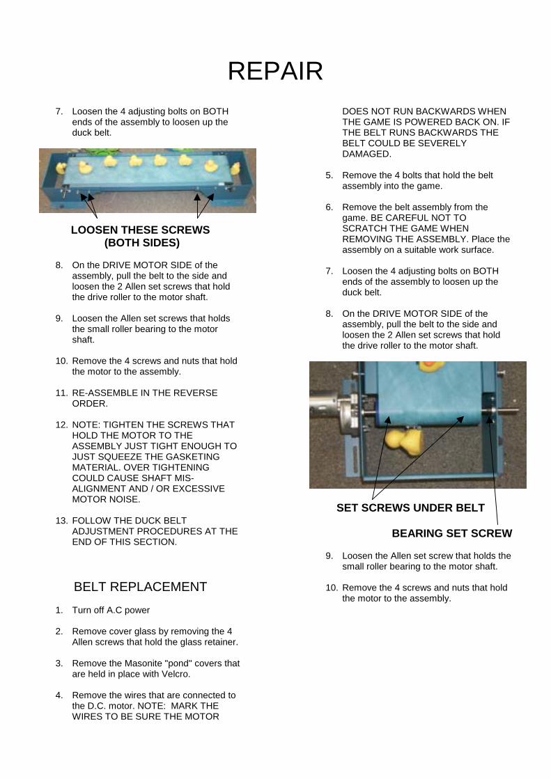
REPAIR7. Loosen the 4 adjusting bolts on BOTH
ends of the assembly to loosen up theduck belt.
LOOSEN THESE SCREWS (BOTH SIDES)
8. On the DRIVE MOTOR SIDE of theassembly, pull the belt to the side andloosen the 2 Allen set screws that holdthe drive roller to the motor shaft.
9. Loosen the Allen set screws that holdsthe small roller bearing to the motorshaft.
10. Remove the 4 screws and nuts that holdthe motor to the assembly.
11. RE-ASSEMBLE IN THE REVERSEORDER.
12. NOTE: TIGHTEN THE SCREWS THATHOLD THE MOTOR TO THEASSEMBLY JUST TIGHT ENOUGH TOJUST SQUEEZE THE GASKETINGMATERIAL. OVER TIGHTENINGCOULD CAUSE SHAFT MIS-ALIGNMENT AND / OR EXCESSIVEMOTOR NOISE.
13. FOLLOW THE DUCK BELTADJUSTMENT PROCEDURES AT THEEND OF THIS SECTION.
BELT REPLACEMENT1. Turn off A.C power
2. Remove cover glass by removing the 4Allen screws that hold the glass retainer.
3. Remove the Masonite "pond" covers thatare held in place with Velcro.
4. Remove the wires that are connected tothe D.C. motor. NOTE: MARK THEWIRES TO BE SURE THE MOTOR
DOES NOT RUN BACKWARDS WHENTHE GAME IS POWERED BACK ON. IFTHE BELT RUNS BACKWARDS THEBELT COULD BE SEVERELYDAMAGED.
5. Remove the 4 bolts that hold the beltassembly into the game.
6. Remove the belt assembly from thegame. BE CAREFUL NOT TOSCRATCH THE GAME WHENREMOVING THE ASSEMBLY. Place theassembly on a suitable work surface.
7. Loosen the 4 adjusting bolts on BOTHends of the assembly to loosen up theduck belt.
8. On the DRIVE MOTOR SIDE of theassembly, pull the belt to the side andloosen the 2 Allen set screws that holdthe drive roller to the motor shaft.
SET SCREWS UNDER BELT
BEARING SET SCREW
9. Loosen the Allen set screw that holds thesmall roller bearing to the motor shaft.
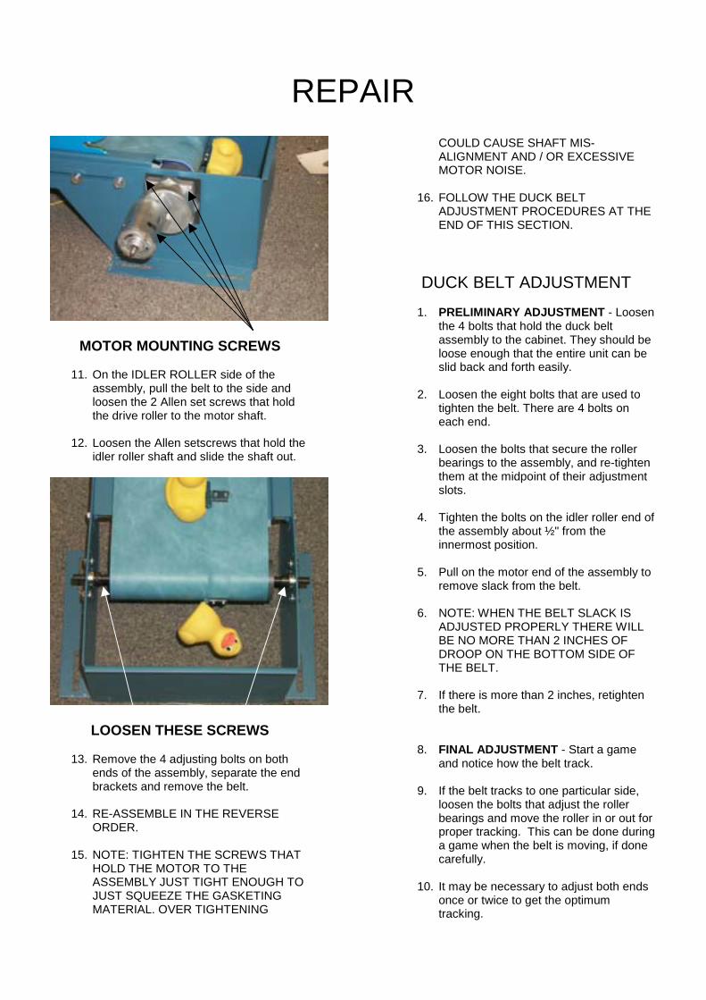
10. Remove the 4 screws and nuts that holdthe motor to the assembly.
REPAIR
MOTOR MOUNTING SCREWS
11. On the IDLER ROLLER side of theassembly, pull the belt to the side andloosen the 2 Allen set screws that holdthe drive roller to the motor shaft.
12. Loosen the Allen setscrews that hold theidler roller shaft and slide the shaft out.
LOOSEN THESE SCREWS
13. Remove the 4 adjusting bolts on bothends of the assembly, separate the endbrackets and remove the belt.
14. RE-ASSEMBLE IN THE REVERSEORDER.
15. NOTE: TIGHTEN THE SCREWS THATHOLD THE MOTOR TO THEASSEMBLY JUST TIGHT ENOUGH TOJUST SQUEEZE THE GASKETINGMATERIAL. OVER TIGHTENING
COULD CAUSE SHAFT MIS-ALIGNMENT AND / OR EXCESSIVEMOTOR NOISE.
16. FOLLOW THE DUCK BELTADJUSTMENT PROCEDURES AT THEEND OF THIS SECTION.
DUCK BELT ADJUSTMENT1. PRELIMINARY ADJUSTMENT - Loosen
the 4 bolts that hold the duck beltassembly to the cabinet. They should beloose enough that the entire unit can beslid back and forth easily.
2. Loosen the eight bolts that are used totighten the belt. There are 4 bolts oneach end.
3. Loosen the bolts that secure the rollerbearings to the assembly, and re-tightenthem at the midpoint of their adjustmentslots.
4. Tighten the bolts on the idler roller end ofthe assembly about ½" from theinnermost position.
5. Pull on the motor end of the assembly toremove slack from the belt.
6. NOTE: WHEN THE BELT SLACK ISADJUSTED PROPERLY THERE WILLBE NO MORE THAN 2 INCHES OFDROOP ON THE BOTTOM SIDE OFTHE BELT.
7. If there is more than 2 inches, retightenthe belt.
8. FINAL ADJUSTMENT - Start a gameand notice how the belt track.
9. If the belt tracks to one particular side,loosen the bolts that adjust the rollerbearings and move the roller in or out forproper tracking. This can be done duringa game when the belt is moving, if donecarefully.
10. It may be necessary to adjust both endsonce or twice to get the optimumtracking.
REPAIR
11. NOTICE: DO NOT LET THE BELTDRAG ACROSS THE DUCK-UPRAMPS. THIS COULD CAUSEDAMAGE OR FRAYING OF THE BELTMATERIAL OR COULD DAMAGE THESEWN BELT SEAM.
BULB REPLACEMENT
ROPE LIGHT
1. Remove the WACKY DUCKS� signfrom the front of the game.
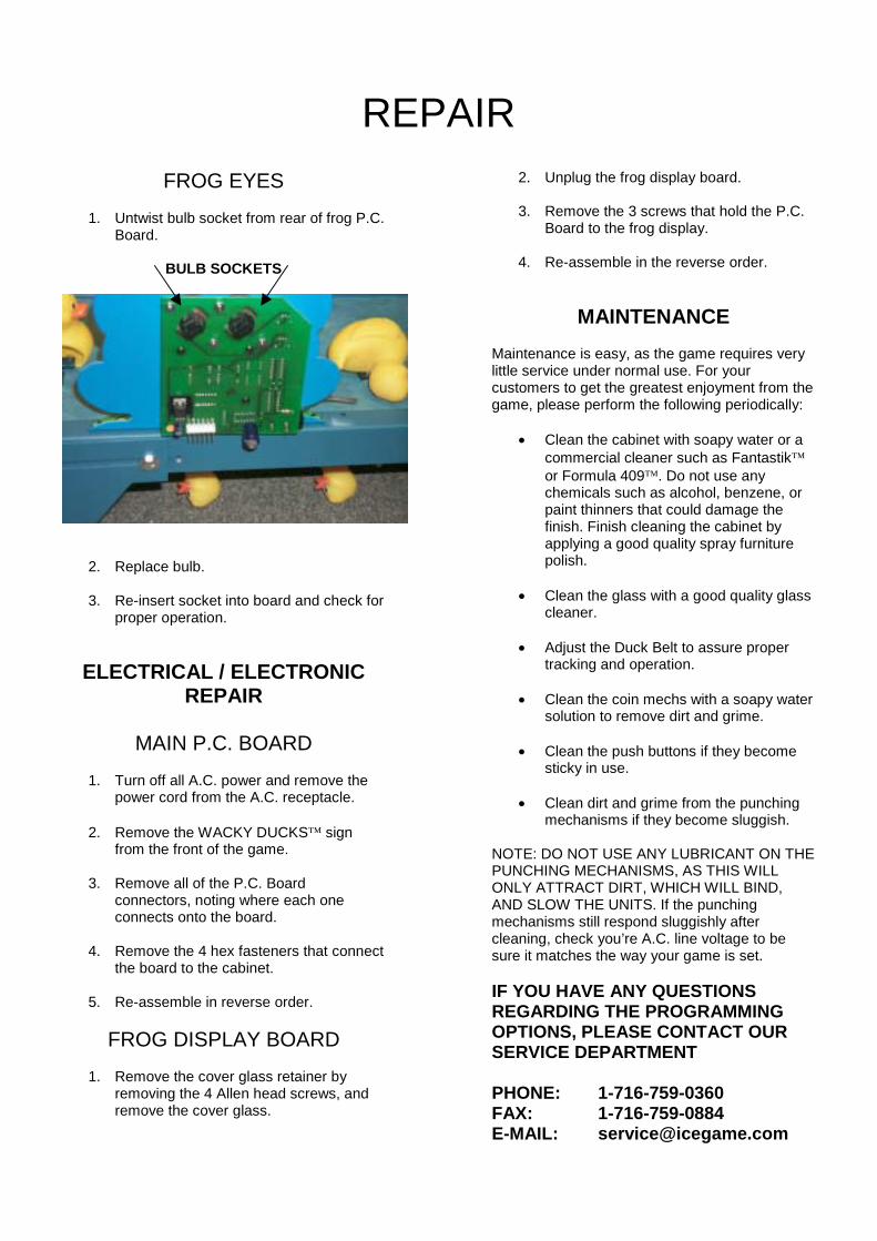
2. Disconnect the rope light connector andthe 2-wire speaker harness.
DISCONNECT WIRES HERE
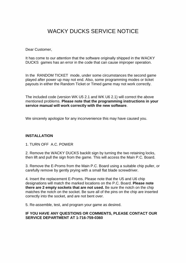
3. Remove the WACKY DUCKS� marqueefrom the game by removing the 5 boltsand washers that hold it to the cabinet.
4. Remove the speaker (duck feet) from themarquee.
REMOVE BOLTS FROM DUCK FEET & DUCKPROFILE
5. Remove the duck graphic from themarquee.
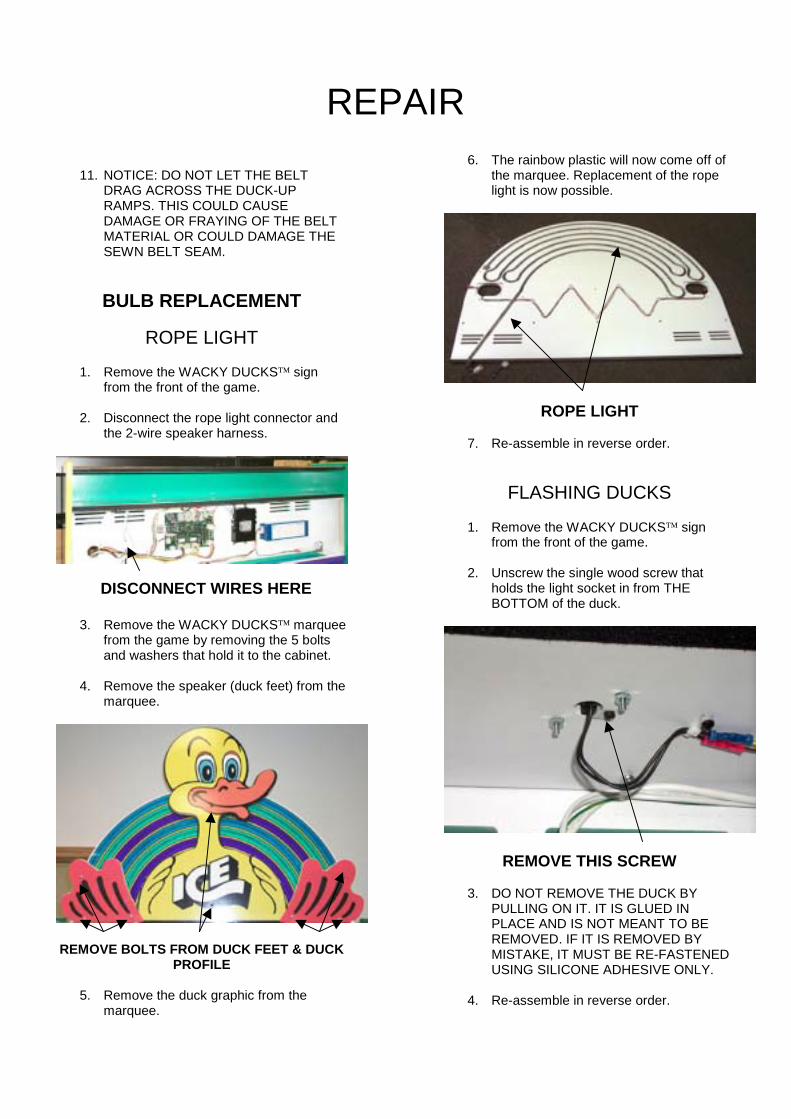
6. The rainbow plastic will now come off ofthe marquee. Replacement of the ropelight is now possible.
ROPE LIGHT
7. Re-assemble in reverse order.
FLASHING DUCKS
1. Remove the WACKY DUCKS� signfrom the front of the game.
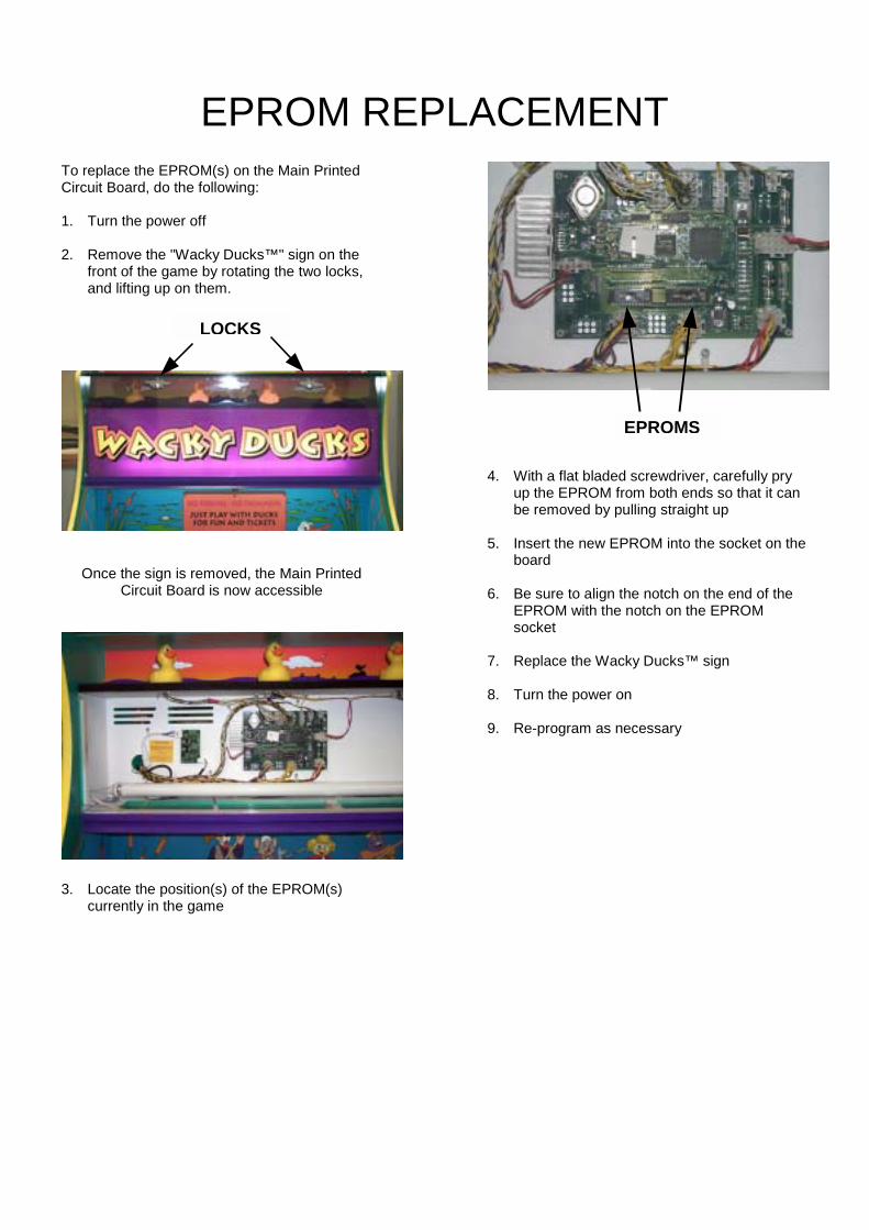
2. Unscrew the single wood screw thatholds the light socket in from THEBOTTOM of the duck.
REMOVE THIS SCREW
3. DO NOT REMOVE THE DUCK BYPULLING ON IT. IT IS GLUED INPLACE AND IS NOT MEANT TO BEREMOVED. IF IT IS REMOVED BYMISTAKE, IT MUST BE RE-FASTENEDUSING SILICONE ADHESIVE ONLY.
4. Re-assemble in reverse order.
REPAIRFROG EYES
1. Untwist bulb socket from rear of frog P.C.Board.
BULB SOCKETS
2. Replace bulb.
3. Re-insert socket into board and check forproper operation.
ELECTRICAL / ELECTRONICREPAIR
MAIN P.C. BOARD1. Turn off all A.C. power and remove the
power cord from the A.C. receptacle.
2. Remove the WACKY DUCKS� signfrom the front of the game.
3. Remove all of the P.C. Boardconnectors, noting where each oneconnects onto the board.
4. Remove the 4 hex fasteners that connectthe board to the cabinet.
5. Re-assemble in reverse order.
FROG DISPLAY BOARD1. Remove the cover glass retainer by
removing the 4 Allen head screws, andremove the cover glass.
2. Unplug the frog display board.
3. Remove the 3 screws that hold the P.C.Board to the frog display.
4. Re-assemble in the reverse order.
MAINTENANCEMaintenance is easy, as the game requires verylittle service under normal use. For yourcustomers to get the greatest enjoyment from thegame, please perform the following periodically:
� Clean the cabinet with soapy water or acommercial cleaner such as Fantastik�or Formula 409�. Do not use anychemicals such as alcohol, benzene, orpaint thinners that could damage thefinish. Finish cleaning the cabinet byapplying a good quality spray furniturepolish.
� Clean the glass with a good quality glasscleaner.
� Adjust the Duck Belt to assure propertracking and operation.
� Clean the coin mechs with a soapy watersolution to remove dirt and grime.
� Clean the push buttons if they becomesticky in use.
� Clean dirt and grime from the punchingmechanisms if they become sluggish.
NOTE: DO NOT USE ANY LUBRICANT ON THEPUNCHING MECHANISMS, AS THIS WILLONLY ATTRACT DIRT, WHICH WILL BIND,AND SLOW THE UNITS. If the punchingmechanisms still respond sluggishly aftercleaning, check you’re A.C. line voltage to besure it matches the way your game is set.
IF YOU HAVE ANY QUESTIONSREGARDING THE PROGRAMMINGOPTIONS, PLEASE CONTACT OURSERVICE DEPARTMENT
PHONE: 1-716-759-0360FAX: 1-716-759-0884E-MAIL: [email protected]
WACKY DUCKS SERVICE NOTICE
Dear Customer,
It has come to our attention that the software originally shipped in the WACKYDUCKS games has an error in the code that can cause improper operation.
In the RANDOM TICKET mode, under some circumstances the second gameplayed after power up may not end. Also, some programming modes or ticketpayouts in either the Random Ticket or Timed game may not work correctly.
The included code (version WK U5 2.1 and WK U6 2.1) will correct the abovementioned problems. Please note that the programming instructions in yourservice manual will work correctly with the new software.
We sincerely apologize for any inconvenience this may have caused you.
INSTALLATION
1. TURN OFF A.C. POWER
2. Remove the WACKY DUCKS backlit sign by turning the two retaining locks,then lift and pull the sign from the game. This will access the Main P.C. Board.
3. Remove the E-Proms from the Main P.C. Board using a suitable chip puller, orcarefully remove by gently prying with a small flat blade screwdriver.
4. Insert the replacement E-Proms. Please note that the U5 and U6 chipdesignations will match the marked locations on the P.C. Board. Please notethere are 2 empty sockets that are not used. Be sure the notch on the chipmatches the notch on the socket. Be sure all of the pins on the chip are insertedcorrectly into the socket, and are not bent over.
5. Re-assemble, test, and program your game as desired.
IF YOU HAVE ANY QUESTIONS OR COMMENTS, PLEASE CONTACT OURSERVICE DEPARTMENT AT 1-716-759-0360
EPROM REPLACEMENTTo replace the EPROM(s) on the Main PrintedCircuit Board, do the following:
1. Turn the power off
2. Remove the "Wacky Ducks™" sign on thefront of the game by rotating the two locks,and lifting up on them.
Once the sign is removed, the Main PrintedCircuit Board is now accessible
3. Locate the position(s) of the EPROM(s)currently in the game
4. With a flat bladed screwdriver, carefully pryup the EPROM from both ends so that it canbe removed by pulling straight up
5. Insert the new EPROM into the socket on theboard
6. Be sure to align the notch on the end of theEPROM with the notch on the EPROMsocket
7. Replace the Wacky Ducks™ sign
8. Turn the power on
9. Re-program as necessary
LOCKS
EPROMS

PARTS LISTINGS
MECHANICAL PARTSFP1019 LEVELER FOOTHD1052 SWIVEL CASTERWA5001 TRIPLE COIN DOORWK1001 CONTROL BOXWK1014 RAMP (DUCK LIFT)WK1020 PUNCH ASSEMBLY BRACKETWK1022 SPRING PLUNGER LINKWK1023 SCISSOR PINWK1025 COIL RETAINER BRACKETWK1026 HINGE WASHER, SQUAREWK1050 BEARING, CONVEYOR ROLLERWK1051 HINGE, DUCK TARGETWK1052 PLUNGER SPRINGWK3005X CONVEYOR ROLLER W / GRITWK3010 PLUNGER LINK BLOCK 1 ½ SQ.WK3011 PLUNGER LINK #1WK3012 PLUNGER LINK #2WK3013 PLUNGER LINK #3WK3014 PLUNGER LINK #4WK3015 PLUNGER LINK, ENDWK3016 PUNCHING GLOVEWK3020 DUCK, SMALL BABYWK3021 DUCK, LARGE MAMAWK4001X CONVEYOR BELT ASSEMBLYWK9001 SERVICE MANUAL
GRAPHICS & DECALS7031 FOR INDOOR USE ONLY DECAL7033 WARNING, POWER DIS DECAL7047 WARNING, VHO BULB ONLYWK7000 OUTSIDE LEFT CABINET DECALWK7001 OUTSIDE RIGHT CABINET DECALWK7002 CABINET INSIDE LEFT DECALWK7003 CABINET INSIDE RIGHT DECALWK7004 FROG DECALWK7005 POND DECALWK7007 REAR BACKDROP DECALWK7008 DUCK DISPLAY DECALWK7009 EYEBALL DECALWK7010 LOWER CABINET FRONT DECALWK7012 LEFT CONTROL PANELWK7013 INSTRUCTION DECAL (TIME)WK7014 RIGHT CONTROL PANELWK7021 PROGRAMMING DECALWK7023 INSTRUCTION DECAL (TICKET)WK7024 FROG "TICKET" DECALWK7025 CLOUDWK7026 RAINBOW MARQUEE BACKGNDWK7028 FRONT HEADER SIGNWK7029 DUCK MARQUEE DECAL
ELECTRICAL /ELECTRONIC PARTS
211 LOW TICKET SWITCH2005 LIGHT BULB, #9062026 THERMAL SWITCH2133CW ROPE LIGHT, CHASING 110 VOLT2364X FAN ASSEMBLYHH5005 TICKET DISPENSERPC20224 12-VOLT COUNTERPC20238 BULB SOCKET, TWISTPC20239 LIGHT BULB, #161WK2001X POWER SUPPLYWK2002X TRANSFORMERWK2007X POWER MODULEWK2008 DRIVE MOTORWK2009 COIL, INCLUDES SLEEVEWK2032X DISPLAY P.C. BOARD ASSEMBLYWK2034X MAIN P.C. BOARD ASSEMBLYWK2133CTLX ROPE LIGHT CONTROLLERWK8284X BALLAST ASSEMBLY
WARRANTYI.C.E warrants all components in the MESMERIZER� game to be free ofdefects in materials and workmanship for a period of ninety days from thedate of purchase.
This warranty does not cover items damaged due to normal wear and tear,subjected to abuse, improperly assembled by the end user, modified,repaired, or operated in a fashion other than that described in the servicemanual.
If your MESMERIZER� game fails to conform to the above-mentionedwarranty, I.C.E.'s sole responsibility shall be at its discretion to repair orreplace any defective component with a new or remanufacturedcomponent of equal to or greater O.E.M. specification.
I.C.E. will assume no liability whatsoever, for costs associated with labor toreplace defective parts, or travel time associated therein.
I.C.E.'s obligation will be to ship free of charge, replacement parts byU.P.S. Ground, U.S. mail, or other comparable shipping means. Anyexpress mail or overnight shipping expense is at the cost of the purchaser.
� Products will be covered under warranty only when:
� The serial number of the game with the defective parts is given.
� The serial number of the defective part, if applicable, is given.
� Defective parts are returned to I.C.E., shipping pre-paid, in a timelyfashion, if requested by I.C.E.
� A copy of the sales receipt is available as proof of purchase uponrequest of I.C.E.
I.C.E. distributors are independent, privately owned and operated. In theirjudgment, they may sell parts or accessories other than thosemanufactured by I.C.E. We cannot be responsible for the quality,suitability, or safety of any non-I.C.E. part, or any modification, includinglabor, which is performed by such a distributor.