Embed Size (px)
Citation preview
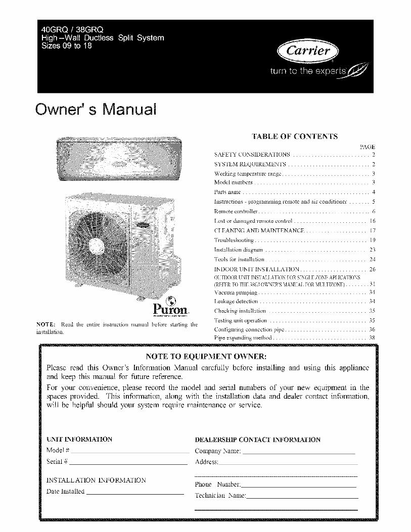
Owner's anual
NOTE: Read the entire instruction manual before starting theinstallation.
TABLE OF CONTENTS
PAGE
SAFETY CONSIDERATIONS ......................... 2
SYSTEM REQUIREMENTS ........................... 2
Working temperature range ............................. 3
Model numbers ...................................... 3
Parts name .......................................... 4
Instructions - programming remote and air conditioner ....... 5
Remote controller ..................................... 6
Lost or damaged remote control ........................ 16
CLEANING AND MAINTENANCE .................... 17
Troubleshooting ..................................... 19
Installation diagram ................................. 23
Tools for installation ................................. 24
INDOOR UNIT INSTALLATION ...................... 26
OUTDOOR UNIT INSTALLATION FOR SINGLE ZONE APLICATIONS
(REFER TO THE 38GJ OWNER'S MANUAL FOR MULTIZONE) ........ 31
Vacuum pumping .................................... 34
Leakage detection ................................... 34
Checking installation ................................ 35
Testing unit operation ................................ 35
Configuring connection pipe ........................... 36
Pipe expanding method ............................... 38
NOTE TO EQUIPMENT OWNER:
Please read this Owner's Information Manual carefully before installing and using this applianceand keep this manual for future reference.
For your convenience, please record the model and serial numbers of your new equipment in thespaces provided. This information, along with the installation data and dealer contact information,will be helpful should your system require maintenance or service.
UNIT INFORMATION
Model #
Serial #
INSTALLATION INFORMATION
Date Installed
DEALERSHIP CONTACT INFORMATION
Company Name:
Address:
Phone Number:
Technician Name:
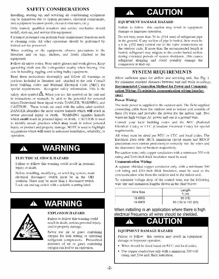
SAFETY CONSIDERATIONS
Installing, starting up, and servicing air-conditioning equipment
can be hazardous due to system pressures, electrical components,
and equipment location (roofs, elevated structures, etc.).
Only trained, qualified installers and service mechanics should
install, start-up, and service this equipment.
Untrained personnel can perform basic maintenance flmctions such
as cleaning coils. All other operations should be performed by
trained service personnel.
When working on the equipment, observe precautions in the
literature and on tags, stickers, and labels attached to the
equipment.
Follow all safety codes. Wear safety glasses and work gloves. Keep
quenching cloth and fire extinguisher nearby when brazing. Use
care in handling, rigging, and setting bulky equipment.
Read these instructions thoroughly and follow all warnings orcautions included in literature and attached to the unit. Consult
local building codes and National Electrical Code (NEC) for
special requirements. Recognize safety information. This is the
safety-alert symbol/_. When you see this symbol on the unit and
in instructions or manuals, be alert to the potential for personal
injury.Understand these signal words: DANGER, WARNING, and
CAUTION. These words are used with the safety-alert symbol.DANGER identifies the most serious hazards which will result in
severe personal injury or death. WARNING signifies hazards
which could result in personal injury or death. CAUTION is used
to identify unsafe practices which may result in nfinor personal
injury or product and property damage. NOTE is used to highlight
suggestions which will result in enhanced installation, reliability, or
operation.
ELECTRICALSHOCK HAZARD
Failure to follow this warning could result in personalinjury or death.
Before installing, modifying, or servicing system, mainelectrical disconnect switch must be in the OFF
position. There may be more than 1 disconnect switch.Lock out and tag switch with a suitable warning label.
EXPLOSION HAZARD
Failure to follow this warning couldresult in death, serious personal iniury,and/or property damage.
Never use air or gases containingoxygen for leak testing or operatingrefrigerant compressors. Pressurizednfixtures of air or gases containingoxygen can lead to an explosion.
EQUIPMENT DAMAGE HAZARD
Failure to follow this caution may result in equipmentdamage or improper operation.
Do not bury more than 36 in. (914 ram) of refrigerant pipein the ground. If any section of pipe is buried, there must bea 6 in. (152 ram) vertical rise to the valve connections onthe outdoor units. If more than the recommended length isburied, refrigerant may nfigrate to the cooler buried sectionduring extended periods of system shutdown. This causesrefrigerant slugging and could possibly damage thecompressor at start-up.
SYSTEM REQUIREMENTSAllow sufficient space for airflow and servicing unit. See Fig. 1for nfinimuna required distances between unit and walls or ceilings.Recommended Connection Method for Power and Communi-
cation Wiring (To minimize communication wiring interfer-enceL
Power Wiring:
The main power is supplied to the outdoor unit. The field suppliedconnecting cable from the outdoor unit to indoor unit consists ofthree (3) wires and provides the power for the indoor unit. Twowires are high voltage AC power and one is a ground wire.
Consult your local building codes and the NEC (NationalElectrical Code) or CEC (Canadian Electrical Code) for specialrequirements.
All wires must be sized per NEC or CEC and local codes. UseElectrical Data table MCA (nfininmm circuit amps) and MOCP(naaxinmm over current protection) to correctly size the wires andthe disconnect fuse or breakers respectively.
Per caution note, only copper conductors with a nfinimuna 300 voltrating and 2/64-inch thick insulation must be used.
Communication Wiring:
A separate shielded copper conductor only, with a nfinimun_ 300volt rating and 2/64-inch thick insulation, must be used as thecommunication wire from the outdoor unit to the indoor unit.
To nfininfize voltage drop of the control wire, use the followingwire size and maxinmna lengths shown in the chart below:
Wire Size Lengthft (m)
18 AWG 50 (15)
16 AWG 50 (15) to 100 (30)
When installing in an application where there is highelectrical frequency all wires should be shielded.
EQUIPMENT DAMAGE HAZARD
Failure to follow this caution may result in equipmentdamage or improper operation.
• Wires should be sized based on NEC and local codes.
• Use copper conductors only with a nfinimuna 300 voltrating and 2/64 inch thick insulation.
-2-
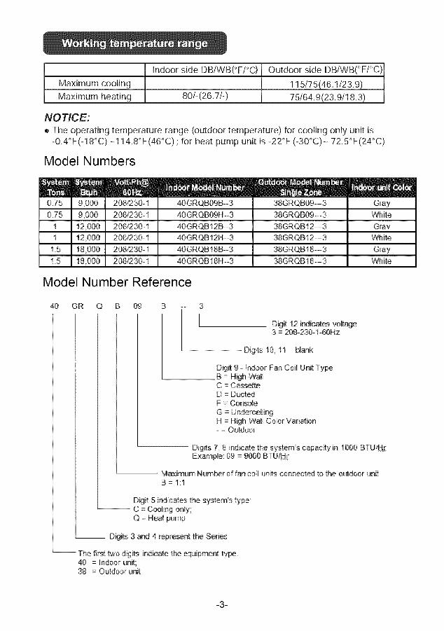
Maximum cooling
Maximum heating
Indoor side DB/WB(°F/°C)
80/-(26.7/-)
Outdoor side DB/WB(°F/°C)
115/75(46.1/23.9)75/64.9(23.9/18.3)
NOTICE:
o The operating temperature range (outdoor temperature) for cooling only unit ts
-0,4°F(-18°C) -114,8°F(46°C) ; for heat pump unit is -22°F (-30°C) - 72,5°F(24°C)
Model Numbers
9 0O0
9,000
12,000
12.000
18,000
18,000
208/230-1
208/230-1
208/230-1
208/230-1
208/230-1
2081230-1
40GRQB09B-3
40GRQB09H--3
40GRQB12B-3
40GRQB12H--3
40GRQB18B--3
40GRQB18H--3
38GRQB09--3
38GRQB09--3
38GRQB12---3
38GRQB12---3
38GRQB18--3
38GRQB18---3
GrayWhite
Gray
White
GrayWhite
Model Number Reference
40 GR Q B 09 B 3
L Digit 12 indicates voltage3 = 208-230-1-60Hz
Digits 10, 11- blank
Digit 9- I_oor Fan Coil:: Unit TypeB = H_h-WaHC = CassetteD = DuctedF -- Console
G = UnderceilingH = High Wall Color Variation- = Outdoor
Digits 7 8 i_icate th_ s;ys_em's capac_y in 1000 BTU/_Example: 09 = 9000 BTULUj:
Maximum Num_r of fan coill units connected to the outdoor unitB = I:1
Digit 5 indicates;the system's type:-- C = Cooling only;
Q = Heat pump
-- Digits 3 and 4 represent the Series
-- The first bwodigits indicate the _uipment type_40 = Indoor unit:;38 = Outdoor unit
-3-
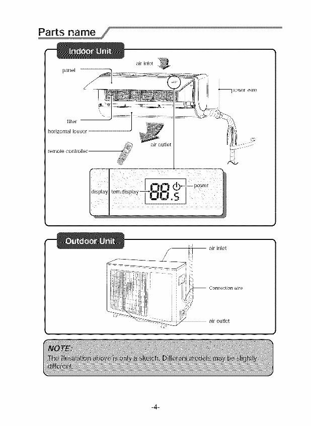
panel
air inlet
filter
horizontal louver
remote controlle[air outle!
)ower wire
-- air inlet
-- Connection wire
-- air outlet
-4-
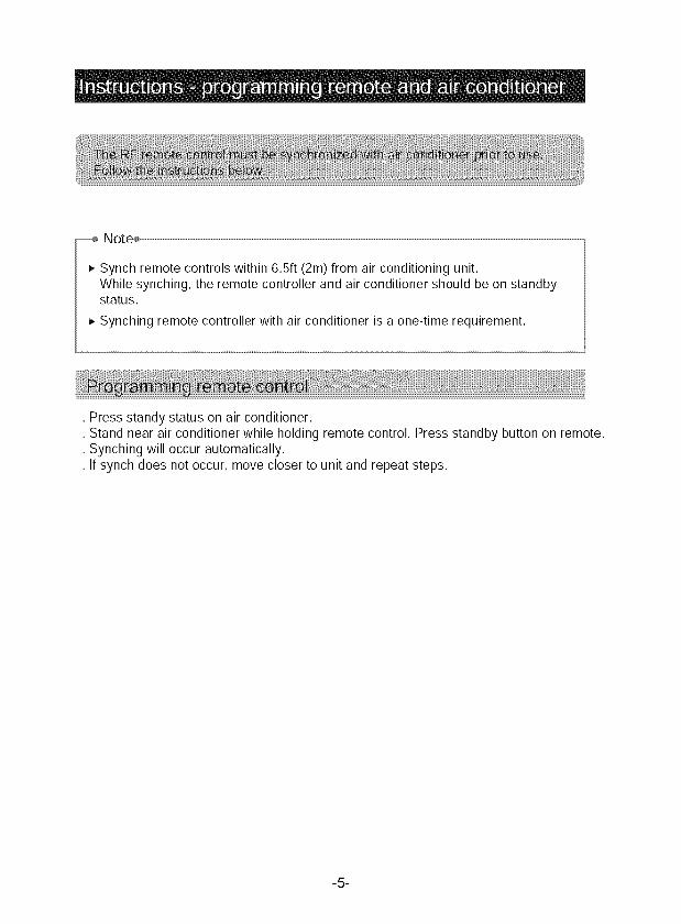
Note÷ .........................................................................................................................................................................................................................................................................................................................................................................................................................................................................................................................................................................................................................................................
_-Synch remote controls within 6.5ft (2m) from air conditioning unit,While synching, the remote controller and air conditioner should be on standbystatus•
_, Synching remote controller with air conditioner is a one-time requirement.
• Press standy status on air conditioner.• Stand near air conditioner while holding remote control. Press standby button on remote.• Synching will occur automatically•• If synch does not occur, move closer to unit and repeat steps•
-5-
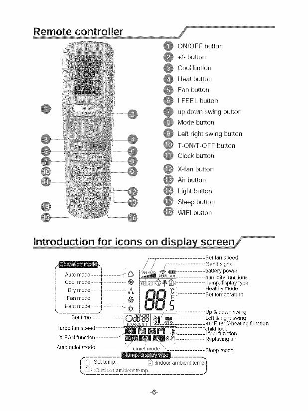
ON/OFFbutton+/-buttonCoolbuttonHeatbuttonFanbuttonI FEELbuttonupdownswingbuttonModebuttonLeftrightswingbuttonT-ON/T-OFFbuttonClockbutton
X-fanbuttonAirbuttonLightbuttonSleepbuttonWIFIbutton
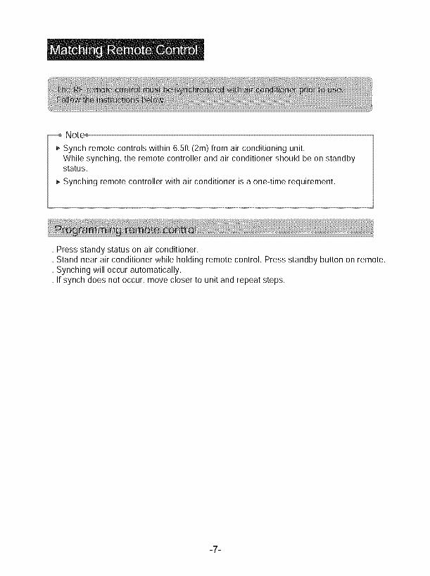
,, ? Set fansvee_n a/ / r,_, / / L Send signal
......... I . f\ FANAUT_"_" _ battery power/<,U[U II IULI_ .... l- ....... _:: P"--'_ _tII__I_,_OPER w_,_i humidity functions1
Cool mode ...._ ....... 4- _ INTELLIGENT_4_'i Temp,displaytype
CFi Healthymode....".......-'" !210: ...........Fan mode .... I- ....... _- _$
, _, O!_.I ,: iHeat mode .... _-....... -:.,............ j _ .21iSet time ............. O3ti 881 " ' Up & down swing31' I-i Left & right swing
ii HOURONOFFJ "_I_......rill\\ i_ 46°F (8°C)heating function
Turbo fan speed :_-_ [] i[_1--:_.i child lock._ ._--...........Ifeelfunction
X-FAN function .......... __ _B _- Replacing air
Auto quiet mode " OuJe( mode ", Sleep mode
, _ :Set temp, _ :Indoor ambient temp._
L. -_2:Out-_-°2ra_ b2e_ntt__mp_.............. )
-6-
Note÷
_-Synch remote controls within 6.Sft (2m) from air conditioning unit•While synching, the remote controller and air conditioner should be on standbystatus•
_, Synching remote controller with air conditioner is a one-time requirement•
• Press standy status on air conditioner.• Stand near air conditioner while holding remote control. Press standby button on remote.• Synching will occur automatically•• If synch does not occur, move closer to unit and repeat steps•
-7-
REMOTE CONTROL FUNCTIONS
Note:o After the air conditioner has been properly installed, you can use the remote
control to operate the air conditioner. Press the power button on the remotecontrol. The green indicator light will display on the air conditioner unit.Follow the instructions for using the remote control.
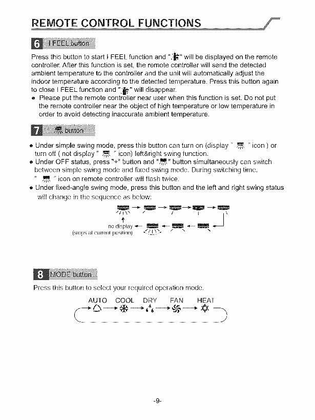
Use the ON/OFF remote button to turn on or turn off the air conditioner.
The button on the remote will display ON when the air conditioner is on.
The +/- button increases or decreases the temperature setting on the airconditioning unit. Hold the %" or "-" for 2s to change the temperature setting.NOTE: Temperature setting can not be adjusted in "auto mode".
Press the "+" or "-" for setting and adjusting TIMER.
Press the Cool button to operate in cool mode.
Press the Heat button to operate in heat mode.
Press the FAN button to adjust the fan circulation speed: low(I), low medium( ,,I ),medium( Jill ), medium high(rill), high(dllll), super, auto and quiet.
Note:J_ Auto _ H
• Turbo function is not available under dry and auto mode.• Automatically operate silent speed when starting sleep fuction.
• The unit operates at low speed under dry and auto dry mode. The speed can'tbe adjusted.
• Under AUTO speed, air conditioner will select proper fan speed automaticallyaccording to ambient temperature.
-8-
Pressthisbuttontostartl FEELfunctionand".:_."willbedisplayedontheremotecontroller.Afterthisfunctionisset,theremotecontrollerwillsendthedetectedambienttemperaturetothecontrollerandtheunitwillautomaticallyadjusttheindoortemperatureaccordingtothedetectedtemperature.PressthisbuttonagaintocloseIFEELfunctionand"'_." willdisappear.• Pleaseputtheremotecontrollernearuserwhenthisfunctionisset,Donotput
theremotecontrollerneartheobjectof hightemperatureor lowtemperatureinordertoavoiddetectinginaccurateambienttemperature.
• Undersimpleswingmode,pressthisbuttoncanturnon (display" ,,_-,," icon) orturnoff( notdisplay" ,,m,," icon)left&rightswingfunction.
• UnderOFFstatus,press"+"buttonand",,,,,u, buttonsimultaneouslycanswitchbetweensimpleswingmodeandfixedswingmode.Duringswitchingtime,
,,.,, icononremotecontrollerwillflashtwice.• Underfixed-angleswingmode,pressthisbuttonandtheleftandrightswingstatus
willchangeinthesequenceasbelow:_ "'"€ _ Ileal
//I \\ / / I \' Jno display_ _ _ _--_
(stops at current position) _/. _.1....\)_ / \ \
Press this button to select your required operation mode.
AUTO COOL DRY FAN HEAT
-9-
REMOTE CONTROL FUNCTIONS
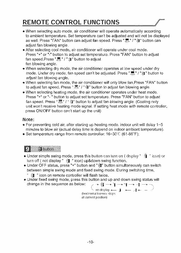
• When selecting auto mode, air conditioner will operate automatically accordingto ambient temperature. Set temperature can't be adjusted and will not be displayedas well. Press "FAN" button can adjust fan speed. Press ",/j\,e,,/"_!" button canadjust fan blowing angle.
• After selecting cool mode, air conditioner will operate under cool mode.Press "+" or "-" button to adjust set temperature. Press "FAN" button to adjustfan speed.Press "e "/" 4 ",m, _1 button to adjustfan blowing angle.
• When selecting dry mode, the air conditioner operates at low speed under drymode. Under dry mode, fan speed can't be adjusted. Press "_ .... "-' "_/_\_1 _1 button toadjust fan blowing angle.
• When selecting fan mode, the air conditioner will only blow fan,Press "FAN" buttonto adjust fan speed. Press " _ .... _ ",m, / _1 button to adjust fan blowing angle.
• When selecting heating mode, the air conditioner operates under heat mode.Press "+" or "-" button to adjust set temperature. Press "FAN" button to adjust
,m, / _1 button to adjust fan blowing angle. (Cooling onlyfan speed. Press " _ .... _ "unit won't receive heating mode signal. If setting heat mode with remote controller,press ON/OFF button can't start up the unit).
Note:
• For preventing cold air, after starting up heating mode, indoor unit will delay 1-5minutes to blow air (actual delay time is depend on indoor ambient temperature).
o Set temperature range from remote controller: 16-30°C (6!-86°F);
• Under simple swing mode, press this button can turn on ( display " _ " icon) orturn off ( not display" 51 " icon) up&down swing function.
• Under OFF status, press "+" button and "_ "3| button simultaneously can switchbetween simple swing mode and fixed swing mode. During switching time,
" 5| " icon on remote controller will flash twice.• Under fixed swing mode, press this button and up and down swing status will
change in the sequence as below: _ 5II ---_ \| ---" 1 ---" -| ---_-_display_-- /| _-- i|
(horizontallouversstops
at current position)
-10-
REMOTE CONTROL FUNCTIONS
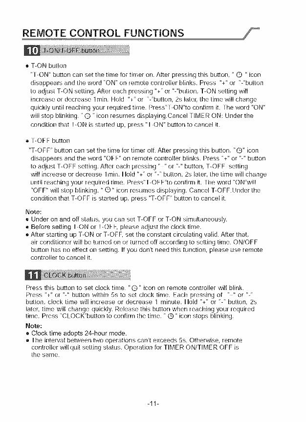
• T-ON button
"T-ON" button can set the time for timer on. After pressing this button, " G " icondisappears and the word "ON" on remote controller blinks. Press "+" or "-"buttonto adjust T-ON setting. After each pressing "+" or "-"button, T-ON setting willincrease or decrease lmin. Hold "+" or "-"button, 2s later, the time will changequickly until reaching your required time. Press"T-ON"to confirm it. The word "ON"will stop blinking. "G " icon resumes displaying.Cancel TIMER ON: Under thecondition that T-ON is started up, press "T-ON" button to cancel it.
e T-OFF button
"T-OFF" button can set the time for timer off. After pressing this button, "G" icondisappears and the word "OFF" on remote controller blinks. Press "+" or "-" buttonto adjust T-OFF setting. After each pressing "+" or "-" button, T-OFF settingwill increase or decrease 1rain. Hold "+" or "-" button, 2s later, the time will changeuntil reaching your required time. Press"T-OFF"to confirm it. The word "ON'will"OFF" will stop blinking. "G" icon resumes displaying. Cancel T-OFF.Under thecondition that T-OFF is started up, press "T-OFF" button to cancel it.
Note:• Under on and off status, you can set T-OFF or T-ON simultaneously.• Before setting T-ON or T-OFF, please adjust the clock time.o After starting up T-ON or T-OFF, set the constant circulating valid. After that,
air conditioner will be turned on or turned off according to setting time. ON/OFFbutton has no effect on setting. If you don't need this function, please use remotecontroller to cancel it.
Press this button to set clock time. "G" icon on remote controller will blink.Press "+" or "-" button within 5s to set clock time. Each pressing of "+" or "-"button, clock time will increase or decrease 1 minute. Hold "+" or "-" button, 2slater, time will change quickly. Release this button when reaching your requiredtime. Press "CLOCK"button to confirm the time. " Q" icon stops blinking.Note:• Clock time adopts 24-hour mode.• The interval between two operations can't exceeds 5s. Otherwise, remote
controller will quit setting status. Operation for TIMER ON/TIMER OFF isthe same.
-11-
REMOTE CONTROL FUNCTIONS
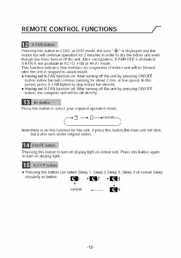
Pressing this button in COOL or DRY mode, the icon "c_" is displayed and theindoor fan will continue operation for 2 minutes in order to dry the indoor unit eventhough you have turned off the unit. After energization, X-FAN OFF is defaulted.X-FAN is not available in AUTO, FAN or HEAT mode.This function indicates that moisture on evaporator of indoor unit will be blowedafter the unit is stopped to avoid mould.• Having set X-FAN function on: After turning off the unit by pressing ON/OFF
button indoor fan will continue running for about 2 min. at low speed. In thisperiod, press X-FAN button to stop indoor fan directly.
• Having set X-FAN function off: After turning off the unit by pressing ON/OFFbutton, the complete unit will be off directly.
Press this button to select your required operation mode.
_f--I, _i" ---_ _ ---_ca ncel_
Note:there is no this function for this unit. It press this button,the main unit will click,but it also runs under original status.
Pressing this button to turn off display light on indoor unit. Press this button againto turn on display light.
• Pressing this button can select Sleep 1, Sleep 2,Sleep 3, Sleep 4 or cancel Sleep
circularly as below: I_lIl _ I1_1.-' _ I_1:'I
tcancel _ II_'-Z
-12-
• InSleep1andSleep2,theairconditionerwillrunaccordingtoa groupofpresettingtemperaturecurves.
• Sleep3 - the sleep curve setting under DIY Sleep mode:(1) Under Sleep 3 mode, long press "AIR" button, the remote controller will enterthe setting of personalized sleep. In this case, the timer zone of remote controllerwill display "1 hr" and the set temperature zone "88" will display the correspondingtemperature of the last set sleep curve and blink (The first entering will displayaccording to the initial curve setting value of manufacturer);
• (2) Press "+" and "-" button to adjust the corresponding temperature. After adjusting,press "AIR" button to confirm it;
• (3) At this time, the timer time on the remote controller will increase automatically by1hr (that is "2 hr" or "3 hr" ,,, or "8 hr"). The set temperature zone "88" will display thecorresponding temperature of the last set sleep curve and blink;
• (4)Repeat step(2) and step (3) until 8-hour temperature setting is finished, then thesleep curve is set successfully. After that, remote controller will resume displaying theoriginal timer time and temperature zone will resume displaying the original settemperature.
• Sleep 3 - the sleep curve inquiry under DIY Sleep mode:User can inquire the set sleep curve according to the setting method of sleep curve.Enter the setting of personalized sleep but do not change the temperature. Thenpress "AIR" button to confirm the setting.Note: In the above setting or inquiry procedure, if there is no button pressing within10s, remote controller will automatically exit the sleep curve setting and resume theHEATING button is pressed during the setting or inquiry procedure, remote controlleroriginal display. If ON/OFF, MODE, TIMER, HUMIDIFY, SLEEP, COOLING orwill also exit the sleep curve setting.
• Sleep 4 is Siesta mode. The set temperature will change automatically according tothe features of siesta.
• Sleep function will be disabled if the air condition is restarted after power failure;when sleep function is turned on, quite fan speed will be also turned on.
• Sleep function can not be set in AUTO mode.
• Press this button 3s can set wifi function on or OFF.
• At OFF status,press mode button and wifi button,can reset wifi mode parameter.and open wifi function.
-13-
REMOTE CONTROL FUNCTIONS-
This function indicates moisture levels will blow away after unit stops to prevent mold.
1.When X-FAN function is on: Press ON/OFF button (on remote) to turn off the unit.The indoor fan will run for approximately 2 minutes at low speed. Press X FAN buttonto stop indoor fan.
2. When X-FAN function is off: Press ON/OFF button (on remote) to turn off complete unit.
The Auto Run mode automatically adjusts to the room's temperature. The LCD on theunit does not show the temperature.
Press "+" and "-" buttons simultaneously to lock or unlock the remote control. If remotecontrol is locked, the icon _ will display; when this occurs press any button on theremote three times. The lock _ will disappear. If the remote is not locked, the lock
f,,
It will not appear.
Make sure the remote control is off. Press MODE and press "C" or "F" to switch betweenfahrenheit and centigrade.
-14-
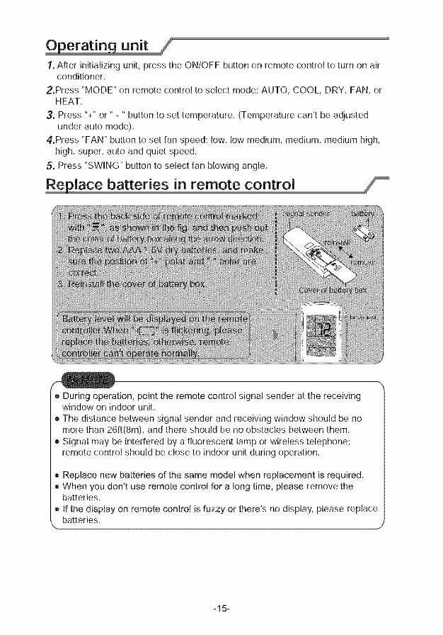
Operating unit1, After initializing unit, press the ON/OFF button on remote control to turn on air
conditioner.
2,Press "MODE" on remote control to select mode: AUTO, COOL, DRY, FAN, orHEAT.
3, Press "+" or .... button to set temperature. (Temperature can't be adjustedunder auto mode).
4,Press "FAN" button to set fan speed: low, low medium, medium, medium high,high, super, auto and quiet speed.
5, Press "SWING" button to select fan blowing angle.
Replace batteries in remote control
• During operation, point the remote control signal sender at the receivingwindow on indoor unit.
• The distance between signal sender and receiving window should be nomore than 26ft(8m), and there should be no obstacles between them.
• Signal may be interfered by a fluorescent lamp or wireless telephone;remote control should be close to indoor unit during operation.
• Replace new batteries of the same model when replacement is required.• When you don't use remote control for a long time, please remove the
batteries.
• If the display on remote control is fuzzy or there's no display, please replacebatteries.
-15-
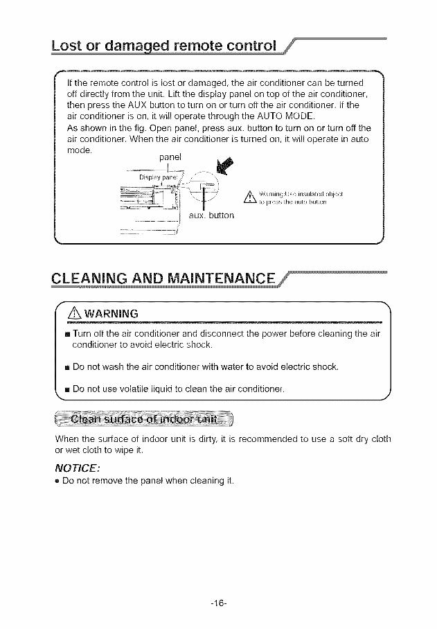
Lost or damaged remote control
If the remote control is lost or damaged, the air conditioner can be turnedoff directly from the unit. Lift the display panel on top of the air conditioner,then press the AUX button to turn on or turn off the air conditioner. If theair conditioner is on, it will operate through the AUTO MODE.As shown in the fig. Open panel, press aux. button to turn on or turn off theair conditioner. When the air conditioner is turned on, it will operate in automode.
panel
Display panel
Z_ Warning:Use insulated objectto press the auto button
aux. button
................... jJ
_,,
WARNING
[] Turn off the air conditioner and disconnect the power before cleaning the airconditioner to avoid electric shock.
[] Do not wash the air conditioner with water to avoid electric shock.
[] Do not use volatile liquid to clean the air conditioner.
When the surface of indoor unit is dirty, it is recommended to use a soft dry clothor wet cloth to wipe it.
NOTICE:
• Do not remove the panel when cleaning it.
-16-
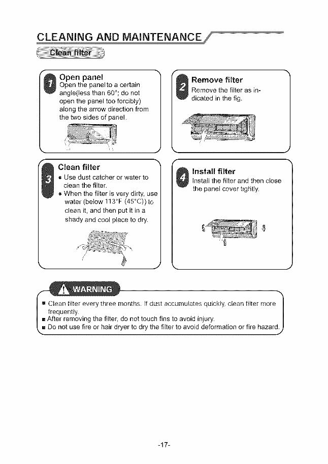
Open panelOpen the panel to a certainangle(less than 60°; do notopen the panel too forcibly)along the arrow direction fromthe two sides of panel.
Clean filter
e Use dust catcher or water toclean the filter,
• When the filter is very dirty, usewater (below 113°F (45°C)) toclean it, and then put it in ashady and cool place to dry.
k,. _ j
f
k.
Remove filter
Remove the filter as in-dicated in the fig.
Install filterInstall the filter and then close
the panel cover twglitly.
h
I Clean filter every three months. If dust accumulates quickly, clean filter more |
frequently. |After removing the filter, do not touch fins to avoid injury. |
Do not use fire or hair dryer to dry the filter to avoid deformation or fire hazard 9
-17-
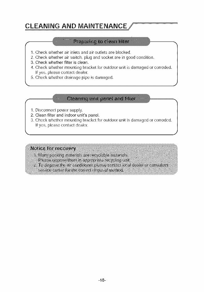
1.Checkwhetherairinletsandairoutletsareblocked.2.Checkwhetherairswitch,plugandsocketareingoodcondition.3.Checkwhetherfilterisclean.4.Checkwhethermountingbracketforoutdoorunitisdamagedorcorroded.
Ifyes,pleasecontactdealer.5.Checkwhetherdrainagepipeisdamaged.
1.Disconnectpowersupply.2. Cleanfilterandindoorunit'spanel.3.Checkwhethermountingbracketforoutdoorunitisdamagedorcorroded.
Ifyes,pleasecontactdealer.
-18-
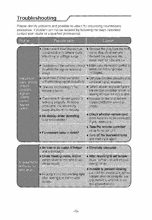
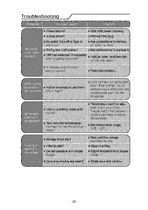
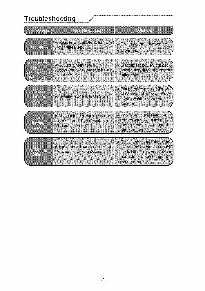
Please identify problems and possible solutions for requesting maintenanceassistance, If problem can not be resolved by following the steps describedcontact your dealer or a quaJified professionN
-20-
-21-
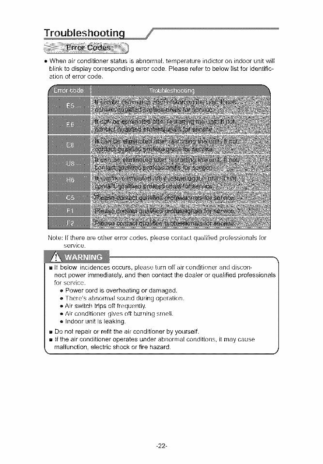
• Whenairconditionerstatusisabnormal,temperatureindictoronindoorunitwillblinktodisplaycorrespondingerrorcode.Pleasereferto belowlistfor identific-ationoferrorcode.
Note:If thereareothererrorcodes,pleasecontactqualifiedprofessionalsforservice.
, If belowincidencesoccurs,pleaseturnoffairconditioneranddiscon-nectpowerimmediately,andthencontactthedealerorqualifiedprofessionalsforservice.
• Powercordisoverheatingordamaged,• There'sabnormalsoundduringoperation.• Airswitchtripsofffrequently.• Airconditionergivesoff burningsmell.• Indoorunitis leaking.
- Do not repair or refit the air conditioner by yourself,[] If the air conditioner operates under abnormal conditions, it may cause
malfunction, electric shock or fire hazard.J
-22-
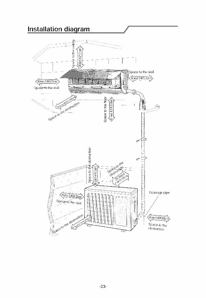
Space to the wall
Drainage pipe
'_ Space to theobstruction
-23-
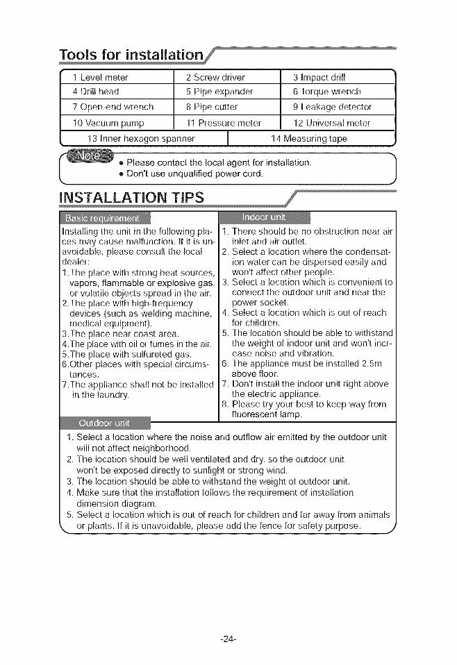
1Levelmeter 2Screwdriver 3 Impactdrill4Drillhead 5Pipeexpander 6Torquewrench7Open-endwrench 8 Pipecutter 9 Leakagedetector
10Vacuumpump 11Pressuremeter 12Universalmeter13Innerhexagonspanner 14Measuringtape
_! Please contact the local agent for installation. _1o Don't use unqualified power cord. J
Installing the unit in the following pla-ces may cause malfunction. If it is un-avoidable, please consult the localdealer:
1 .The place with strong heat sources,vapors, flammable or explosive gas,or volatile objects spread in the air.
2.The place with high-frequencydevices (such as welding machine,medical equipment).
3.The place near coast area.4.The place with oil or fumes in the air.5.The place with sulfureted gas.6.Other places with special circums-
tances.7.The appliance shall not be installed
in the laundry.
1. There should be no obstruction near airinlet and air outlet.
2. Select a location where the condensat-ion water can be dispersed easily andwon't affect other people.
3. Select a location which is convenient toconnect the outdoor unit and near thepower socket.
4. Select a location which is out of reachfor children.
5. The location should be able to withstandthe weight of indoor unit and won't incr-ease noise and vibration.
6. The appliance must be installed 2.5mabove floor.
7. Don't install the indoor unit right abovethe electric appliance.
8. Please try your best to keep way fromfluorescent lamp.
1. Select a location where the noise and outflow air emitted by the outdoor unitwill not affect neighborhood.
2. The location should be well ventilated and dry, so the outdoor unitwon't be exposed directly to sunlight or strong wind.
3. The location should be able to withstand the weight of outdoor unit.4. Make sure that the installation follows the requirement of installation
dimension diagram.5. Select a location which is out of reach for children and far away from animals
,, or plants. If it is unavoidable, please add the fence for safety purpose, j
-24-
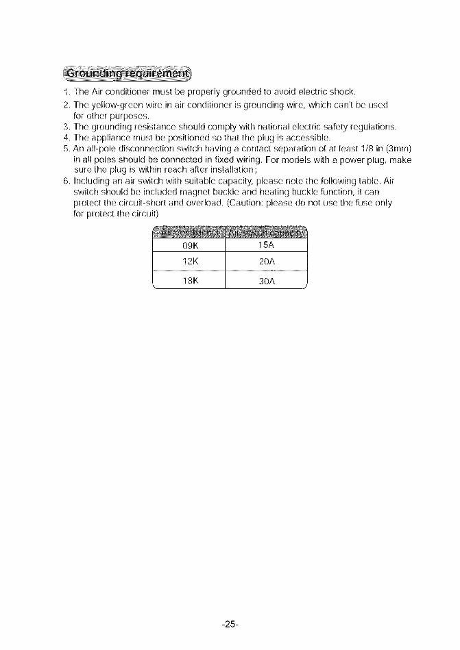
1.TheAirconditionermustbeproperlygroundedto avoidelectricshock.2.Theyellow-greenwireinairconditionerisgroundingwire,whichcan'tbeused
forotherpurposes.3.Thegroundingresistanceshouldcomplywithnationalelectricsafetyregulations.4.Theappliancemustbepositionedsothattheplugisaccessible.5.Anall-poledisconnectionswitchhavingacontactseparationof atleast1/8in (3mm)
inallpolesshouldbeconnectedinfixedwiring.Formodelswithapowerplug,makesuretheplugiswithinreachafterinstallation;
6. Includinganairswitchwithsuitablecapacity,pleasenotethefollowingtable.Airswitchshouldbeincludedmagnetbuckleandheatingbucklefunction,itcanprotectthecircuit-shortandoverload.(Caution:pleasedonotusethefuseonlyforprotectthecircuit)
09K12K
18K
15A
20A
30A
-25-
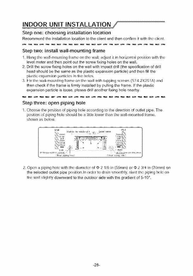
Step one: choosing installation locationRecommend the installation location to the client and then confirm it with the client.
Step two: install wall-mounting frame
1. Hang the wall-mounting frame on the wall; adjust it in horizontal position with thelevel meter and then point out the screw fixing holes on the wall.
2. Drill the screw fixing holes on the wall with impact drill (the specification of drillhead should be the same as the plastic expansion particle) and then fill theplastic expansion particles in the holes.
3. Fix the wall-mounting frame on the wall with tapping screws (ST4.2X25TA) andthen check if the frame is firmly installed by pulling the frame. If the plasticexpansion particle is loose, please drill another fixing hole nearby.
m m m _ W m _ _ m m m _ _ m m m _ m m m _ m m m _
Step three: open piping hole
1. Choose the position of piping hole according to the direction of outlet pipe. Theposition of piping hole should be a little lower than the wall-mounted frame,shown as below.
Wall Wall
(Rear piping hole) (Rear piping hole)
2. Open a piping hole with the diameter of ¢ 2 1/6 in (55ram) or ¢ 2 3/4 in (70ram) onthe selected outlet pipe position.In order to drain smoothly, slant the piping hole onthe wall slightly downward to the outdoor slde wlth the gradLent of 5-10 °.
-26-
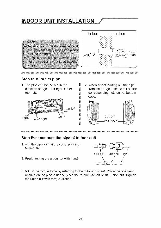
Indoor -- outdoor
qb2 1/6in(55mm)/d# 2 3/4in (70mm)
Step four: outlet pipe
1. The pipe can be led out in thedirection of right, rear right, left orrear left.
,_ear left
right re_arright \et_
JJJJJ
!JJ
2. When select leading out the pipefrom left or right, please cut off thecorresponding hole on the bottomcase.
left
r__ _ ii!!iiii_i_i_i_i_i_i_i_i_i_i'itii_'_'i!!!!!!!!!!i_'_'iiiiiiiiii i
cut off '
_the hole_
Step five: connect the pipe of indoor unit
1. Aim the pipe joint at the correspondingbellmouth.
2. Pretightening the union nut with hand. pipe joint union nut _,ipe
3. Adjust the torque force by referring to the following sheet. Place the open-endwrench on the pipe joint and place the torque wrench on the union nut. Tightenthe union nut with torque wrench.
-27-
torque wrench
findoor pipe
open-end
union nut
pipe
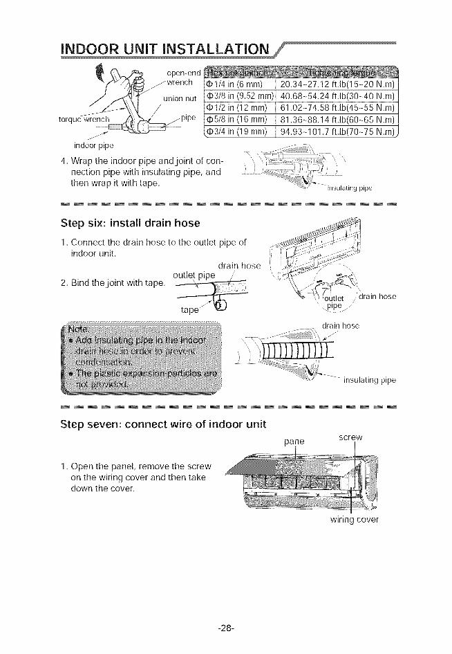
4. Wrap the indoor pipe and joint of con-nection pipe with insulating pipe, andthen wrap it with tape.
¢1/4 in (6 ram) 20.34-27.12 ft.lb(15-20 N.m)¢3/8 in (9.52 ram) 40.68-54.24 ft.lb(30-40 N.m)qbl/2 in (12 ram) 61.02-74.58 ft.lb(45-55 N.m)¢5/8 in (16 ram) 81.36-88.14 ft.lb(60-65 N.m)
_qb3/4in (19 ram) 94.93-101.7 ft.lb(70-75 N.m'
\ \ _ j_ ...............z \ \
insulating pipe
Step six: install drain hose
1. Connect the drain hose to the outlet pipe ofindoor unit.
drain hose
2. Bind the joint with tape.
_
ii __- -\
_% '_,_(OpU_et_" dra,n hose
:5_r!iiiiiiil
drain hose
insulating pipe
Step seven: connect wire of indoor unit
panescrew
1. Open the panel, remove the screwon the wiring cover and then takedown the cover.
wiring cover
-28-
INDOOR UNIT INSTALLATION
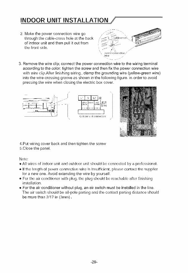
2. Make the power connection wire gothrough the cable-cross hole at the backof indoor unit and then pull it out fromthe front side.
3. Remove the wire clip; connect the power connection wire to the wiring terminalaccording to the color; tighten the screw and then fix the power connection wirewith wire clip.After finishing wiring, clamp the grounding wire (yellow-green wire)into the wire-crossing groove as shown in the following figure, in order to avoidpressing the wire when closing the electric box cover.
/-........................... _t
........
-.\
white black red I,g teen i(blue) [ I(brown) I_/ell°w:
!:__4__t:_4ooo,,Outdoor unit connection ,
4.Put wiring cover back and then tighten the screw5.Close the panel.
Note:
• All wires of indoor unit and outdoor unit should be connected by a professional.
• If the length of power connection wire is insufficient, please contact the supplierfor a new one. Avoid extending the wire by yourself.
• For the air conditioner with plug, the plug should be reachable after finishinginstallation.
• For the air conditioner without plug, an air switch must be installed in the line.The air switch should be all-pole parting and the contact parting distance shouldbe more than 2/17 in (3mm).
-29-
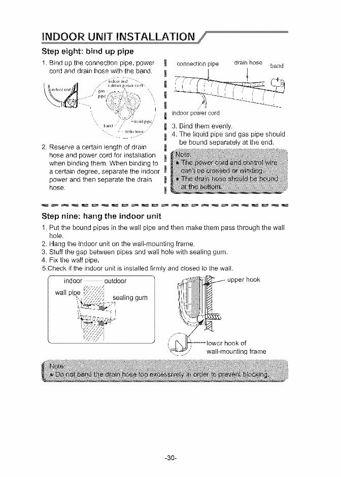
Step eight: bind up pipe
1. Bind up the connection pipe, powercord and drain hose with the band.
Jfi'ndoor and '-_\
__ _ outdaar_eor_\/ gas ..... \
....... -" pipe
\\ , liquid pipe//
\',_b//and see_drain he
2. Reserve a certain length of drainhose and power cord for installationwhen binding them. When binding toa certain degree, separate the indoorpower and then separate the drainhose.
I
I
connection pipe drain hose band
indoor power cord
3. Bind them evenly.4. The liquid pipe and gas pipe should
be bound separately at the end.
Step nine: hang the indoor unit
1. Put the bound pipes in the wall pipe and then make them pass through the wallhole.
2. Hang the indoor unit on the wall-mounting frame.3. Stuff the gap between pipes and wall hole with sealing gum.4. Fix the wall pipe.5.Check if the indoor unit is installed firmly and closed to the wall.
indoor outdoor
wall '_
p_pe = sealing gum
-30-
CAUTION NOTE
EQUIPMENT DAMAGE HAZARD
Failure to fi_llow this caution may result in equipment damage or improper operation.In regions with snowfall and cold temperatures, avoid installing the outdoor unit in areas where it canbe covered by snow. If the outdoor unit is installed in areas where heavy snow is expected, a fieldsupplied ice or snow stand and!or field suppfied-qnstalled wind baffle should be installed to protect theunit from snow accumulation and!or blocked air intake. Blocking the air intake may result in reducedairflow, significantly reduced performance and damage to the equipment.
OUTDOORUNiT iNSTALLATiONFORSINGLEZONEAPLICATIONS
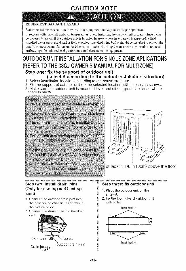
(REFERTOTHE38GJ OWNER'SMANUALFORMULTffONE)Step one: fix the support of outdoor unit
(select it according to the actual installation situation)1. Select installation location according to the house structure.2. Fix the support of outdoor unit on the selected location with expansion screws.3. Make sure the outdoor unit is mounted level and off the ground in areas where
there is snow.
at least 1 1/6 in (3cm) above the floor
Step two: install drainjoint
(Only for cooling and heating
unit)
1. Connect the outdoor drain joint intothe hole on the chassis, as shown in
the picture below.2. Connect the drain hose into the drain
vent.
drain ve "chassis
outdoor drain joint
Drain h_
IIIII
II!
Step three: fix outdoor unit
1. Place the outdoor unit on the
support.2. Fix the foot holes of outdoor unit
with bolts.
foot holes
foot holes
-31-
OUTDOORUNITINSTALLATIONFORSINGLEZONEAPLICATIONS_!REFERTOTHE38GJOWNER'SMANUALFORMULTIZONE) /
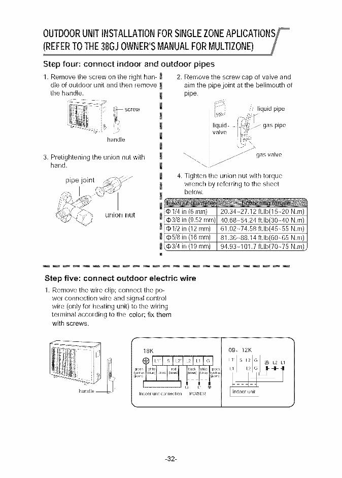
Step four: connect indoor and outdoor pipes
1. Remove the screw on the right han-dle of outdoor unit and then remove
the handle.
screw
handle
3. Pretightening the union nut withhand.
pipe joint
union nut
IIIIIIIIIIIII!I
2. Remove the screw cap of valve andaim the pipe joint at the bellmouth ofpipe.
// liquid pipe
liquid .....l_ gas pipe
valve _
gas valve
4. Tighten the union nut with torquewrench by referring to the sheetbelow.
¢1/4 in (6 ram)¢3/8 in (9.52 mm)¢1/2 in (12 mm)
¢5/8 in (16 ram)qb3/4 in (19 ram)
20.34-27.12 ft.lb(15-20 N.m)40.68-54.24 ft.lb(30-40 N.m)61.02-74.58 ft.lb(45-55 N.m)
81.36-88.14 ft.lb(60-65 N.m)94.93-101.7 ft.lb(70-75 N.m'
Step five: connect outdoor electric wire
1. Remove the wire clip; connect the po-wer connection wire and signal controlwire (only for heating unit) to the wiringterminal according to the color; fix themwith screws.
handle
18K
@ L_l,I_I_,1_1_11oj
0,oon,_ i___/__Foo,,,
Indoor unit connection POWER
k.
09, 12K
1' S L2' G (_ L2
Indoor unit I
-32-
2. Fix the power connection wire and signal control wire with wire clip (only forcooling and heating unit).
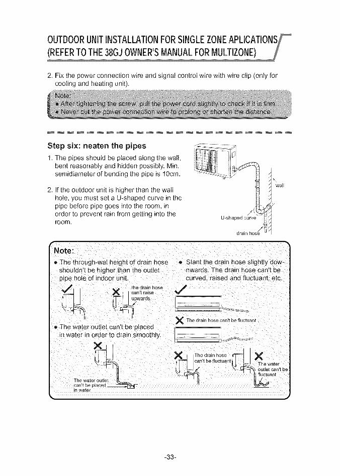
Step six: neaten the pipes
1. The pipes should be placed along the wall,bent reasonably and hidden possibly. Min.semidiameter of bending the pipe is lOcm.
2. If the outdoor unit is higher than the wallhole, you must set a U-shaped curve in thepipe before pipe goes into the room, inorder to prevent rain from getting into theroom.
U-shaped curve
drain hosej_
_wall
_-- _1I
Note:
• The through-wal height of drain hose o Slant the drain hose slightly dow-
shouldn't be higher than the outletpipe hole of indoor unit.
_. _ , _.._ the drain hose_I can't raise
._. _wards.
® The water outlet can't be pacedin water in order to drain smoothly.
The ware u_
can,t be p;a°cUe_de' _in water
inwards. The drain hose can t becurved, raised and fluctuant, etc.C
X The drain hose can't be fluctuant
f_ cThnet_:if/uhct_:nt _ XThe water
-33-
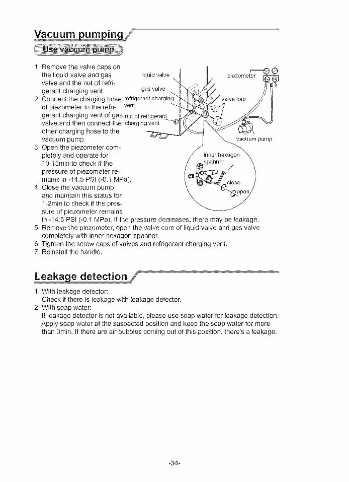
1.RemovethevalvecapsonI--
the liquid valve and gas liquidvalve piezometervalve and the nut of refri-gerant charging vent. gas valve
2. Connect the charging hose refrigerantchar_ cap
of piezometer to the refri- vent
gerant charging vent of gas nut of refrigerarvalve and then connect the chargingvent
other charging hose to thevacuum pump.
3. Open the piezometer com-pletely and operate for10-15rain to check if the
pressure of piezometer re-mains in -14.5 PSI (-0.1 MPa).
4. Close the vacuum pumpand maintain this status for
1-2rain to check if the pres-sure of piezometer remainsin -14.5 PSi (-0.1 MPa). If the pressure decreases, there may be leakage.
5. Remove the piezometer, open the valve core of liquid valve and gas valvecompletely with inner hexagon spanner.
6. Tighten the screw caps of valves and refrigerant charging vent.7. Reinstall the handle.
vacuum pump
1. With leakage detector:Check if there is leakage with leakage detector.
2. With soap water:If leakage detector is not available, please use soap water for leakage detection.Apply soap water at the suspected position and keep the soap water for morethan 3min. If there are air bubbles coming out of this position, there's a leakage.
-34-
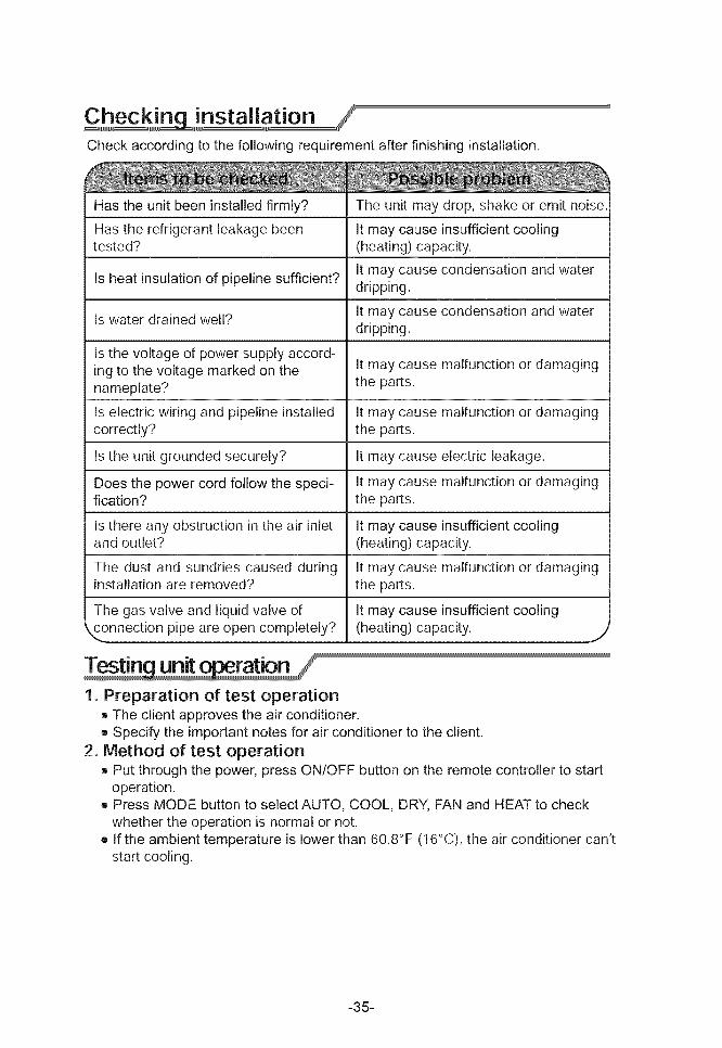
Checkaccordingtothefollowingrequirementafterfinishinginstallation.
Has the unit been installed firmly? The unit may drop, shake or emit noise.
Has the refrigerant leakage been It may cause insufficient coolingtested? (heating) capacity.
It may cause condensation and waterIs heat insulation of pipeline sufficient?
dripping.
It may cause condensation and waterIs water drained well?dripping.
Is the voltage of power supply accord-ing to the voltage marked on the It may cause malfunction or damagingnameplate? the parts.
Is electric wiring and pipeline installed It may cause malfunction or damagingcorrectly? the parts.
Is the unit grounded securely? It may cause electric leakage.
Does the power cord follow the speci- It may cause malfunction or damagingfication? the parts.
Is there any obstruction in the air inlet It may cause insufficient coolingand outlet? (heating) capacity.
The dust and sundries caused during It may cause malfunction or damaginginstallation are removed? the parts.
The gas valve and liquid valve of It may cause insufficient coolingconnection pipe are open completely? (heating) capacity.
J
1. Preparation of test operation• The client approves the air conditioner.• Specify the important notes for air conditioner to the client.
2. Method of test operation• Put through the power, press ON/OFF button on the remote controller to start
operation.• Press MODE button to select AUTO, COOL, DRY, FAN and HEAT to check
whether the operation is normal or not.• If the ambient temperature is lower than 60.8°F (16°C), the air conditioner can't
start cooling.
-35-
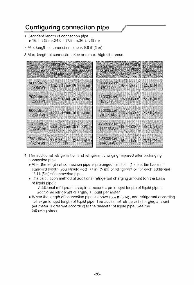
Cjnf guring connection pipe1. Standard length of connection pipe
• 16.4 ft (5 m),24.6 ft (7.5 m),26.2 ft (8 m)
2.Min. length of connection pipe is 9.8 ft (3 m).
3.Max. length of connection pipe and max. high difference.
4. The additional refrigerant oil and refrigerant charging required after prolongingconnection pipe• After the length of connection pipe is prolonged for 32.8 ft (10m) at the basis of
standard length, you should add 1/3 in3(5 ml) of refrigerant oil for each additional16.4ft (5 m) of connection pipe.
• The calculation method of additional refrigerant charging amount (on the basisof liquid pipe):
Additional refrigerant charging amount = prolonged length of liquid pipe xadditional refrigerant charging amount per meter
• When the length of connection pipe is above 16.4 ft (5 m), add refrigerant accordingtothe prolonged length of liquid pipe. The additional refrigerant charging amountper meter is different according to the diameter of liquid pipe. See thefollowing sheet.
-36-
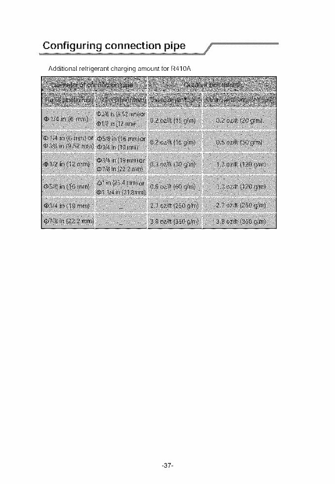
AdditionalrefrigerantchargingamountforR410A
y2ml
mn
-37-
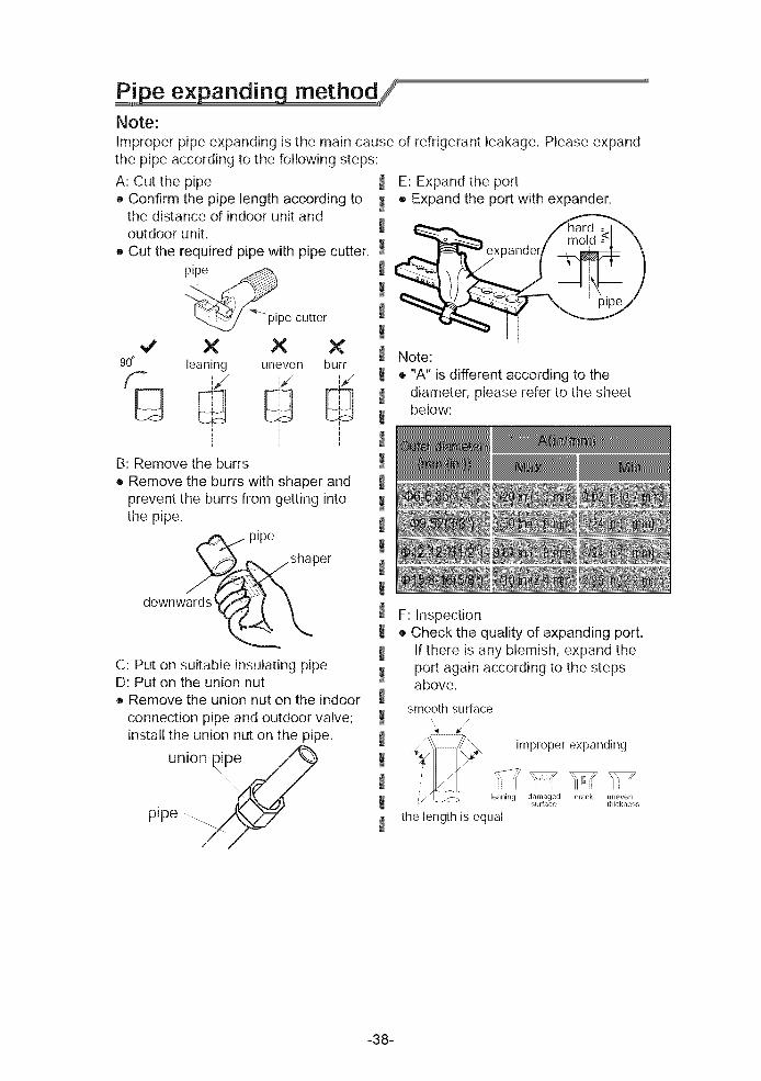
P,i.pe expanding method_Note:Improper pipe expanding is the main cause of refrigerant leakage. Please expandthe pipe according to the following steps:
A: Cut the pipe _ E: Expand the port
• Confirm the pipe length according to _ • Expand the port with expander.the distance of indoor unit andoutdoor unit.
• Cut the required pipe with pipe cutter.
90° i
E
ii
_pe cutter
X × Xleaning uneven burr
i i i
B: Remove the burrs
• Remove the burrs with shaper andprevent the burrs from getting intothe pipe.
pipe
)er
downwards
C: Put on suitable insulating pipeD: Put on the union nut• Remove the union nut on the indoor
connection pipe and outdoor valve;install the union nut on the pipe.
union pipe
pipe .....
!!!!!!!!!!!!!!!!!!!!!!!!!!!
Note:
• "A" is different according to thediameter, please refer to the sheetbelow:
F: Inspection• Check the quality of expanding port.
If there is any blemish, expand theport again according to the stepsabove.
smooth surface
improper expanding
leaning damagedsurface
the length is equal
crack uneventhickness
-38-

66129916984
Copyright 2014 Carrier Corporation • 7310 W, Morris St. • Indianapolis, IN 46231 Edition Date: 11/14
Manufacturer reserves the right to change, at any time, specifications and designs without notice and without obligations,
Catalog No: 38-40GR-O10M
Replaces: New