Embed Size (px)
Citation preview
go
HONDAGOLDWINGGL1500
OWNER'S MANUAL •
MANUAL DE EXPLICACIONES •
INSTRUKTIEBOEK •
© HONDA MOTOR CO., LTD 1989

goIMPORTANT NOTICE
• OPERATOR AND PASSENGER
This motorcycle is designed to carry the operator and onepassenger. Never exceed the maximum weight capacity asshown on the tyre information label.
• ON-ROAD USE
This motorcycle is designed to be used only on the road.
• READ THIS OWNER'S MANUAL CAREFULLY
Pay special attention to statements preceded by thefollowing words:
IBmIndicates a strong possibility of severe personal injury ordeath if instructions are not followed.
CAUTION:Indicates a possibility of personal injury or equipmentdamage if instructions are not followed.
NOTE: Gives helpful information.
This manual should be considered a permanent part of themotorcycle and should remain with the motorcycle whenresold.

goHONDA GOLDWING
GL1500OWNER'S MANUAL
All information in this publication is based on the latest production information available at the time of approval for printing.HONDA MOTOR CO., LTO. reserves the right to make changesat any time without notice and without incurring any obligation.No part of this publication may be reproduced without writtenpermission.
goWELCOME
The motorcycle presents you a challenge to master themachine, a challenge to adventure. You ride through the wind,linked to the road by a vehicle that responds to your commands as no other does. Unlike an automobile, there is nometal cage around you. Like an airplane, a pre-ride inspectionand regular maintenance are essential to your safety. Yourreward is freedom.
To meet the challenges safely, and to enjoy the adventure fully,you should become thoroughly familiar with this owner'smanual BEFORE YOU RIDE THE MOTORCYCLE.
When service is required, remember that your Honda dealerknows your motorcycle best. If you have the requiredmechanical "know-how" and tools, your dealer can supplyyou with an official Honda Service Manual to help you performmany maintenance and repair tasks.
Pleasant riding, and thank you for choosing a Hondal

goOPERATION
Page1 MOTORCYCLE SAFETY4 Safe Riding Rules5 Protective Apparel5 Modifications6 Loading and Accesso
ries
9 PARTS LOCATION12 Instruments and Indi
cators
18 MAJOR COMPONENTS(Information you need tooperate this motorcycle)
18 Rear Suspension21 Brakes23 Clutch24 Coolant26 Fuel29 Engine Oil30 Final Drive Oil31 Tubeless Tyres
34 ESSENTIAL INDIVIDUALCOMPONENTS
34 Ignition Switch35 Right Handlebar Con
trols39 Left Handlebar Con
trols
41 FEATURES (Not requiredfor operation)
41 Steering Lock
CONTENTS
Page41 Helmet Holders42 Travel Trunk And
Saddlebags46 Fairing Pockets47 Trunk Side Pockets47 Windshield Height Ad
justment48 Headlight Beam Ad-
justment48 Ventilation Louvers49 Seat49 ACC Terminal50 Protection Against
Water50 Radio/Cassette Cover52 AM/FM Radio54 Cassette Deck60 Radio Antenna
61 OPERATION61 Pre-ride Inspection62 Starting the Engine65 Running-in66 Riding67 Reverse Riding69 Braking70 Parking70 Anti-theft Tips

goCONTENTS
MAINTENANCE
Page71 MAINTENANCE72 Maintenance Schedule74 Tool Kit75 Serial Numbers75 Colour Label76 Maintenance Precau-
tions77 Air Cleaner78 Crankcase Breather79 Engine Oil83 Spark Plugs85 Final Drive Oil86 Idle Speed
Page87 Side Stand88 Front Wheel Removal92 Rear Wheel Removal95 Brake Pad Wear96 Battery98 Fuse Replacement
101 CLEANING
103 STORAGE GUIDE103 Storage104 Removal From Storage
105 SPECIFICATIONS
107 NOISE EMISSION(AUSTRALIA ONLY)

goMOTORCYCLE SAFETY
DRIVE CAUTION LABEL
ACCESSORIES AND LOADINGWARNING LABEL
1
goMOTORCYCLE SAFETY
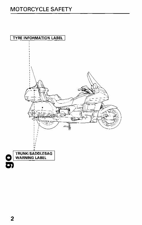
I TVRE INFORMATION LABEL I
IIIIII II IIfI III
"1/
2
go
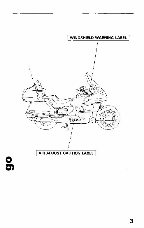
WINDSHIELD WARNING LABEL
AIR ADJUST CAUTION LABEL
3
goMOTORCYCLE SAFETY
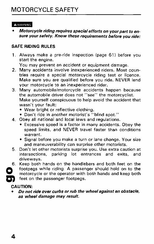
..-• Motorcycle riding requires special efforts on your part to en
sure your safety. Know these requirements before you ride:
SAFE RIDING RULES
1. Always make a pre-ride inspection (page 61) before youstart the engine.You may prevent an accident or equipment damage.
2. Many accidents involve inexperienced riders. Most countries require a special motorcycle riding test or licence.Make sure you are qualified before you ride. NEVER lendyour motorcycle to an inexperienced rider.
3. Many automobile/motorcycle accidents happen becausethe automobile driver does not usee" the motorcyclist.Make yourself conspicuous to help avoid the accident thatwasn't your fault:• Wear bright or reflective clothing.• Don't ride in another motorist's ublind spot."
4. Obey all national and local laws and regulations.• Excessive speed is a factor in many accidents. Obey the
speed limits, and NEVER travel faster than conditionswarrant.
• Signal before you make a turn or lane change. Your sizeand maneuverability can surprise other motorists.
5. Don't let other motorists surprise you. Use extra caution atintersections, parking lot entrances and exits, anddriveways.
6. Keep both hands on the handlebars and both feet on thefootpegs while riding. A passenger should hold on to themotorcycle or the operator with both hands and keep bothfeet on the passenger footpegs.
CAUTION:• Do not ride over curbs or rub the wheel against an obstacle,
as wheel damage may result.
4

goPROTECTIVE APPAREL
1. Most Motorcycle accident fatalities are due to head injuries:ALWAYS wear a helmet. You should also wear a faceshield or goggles as well as boots, gloves, and protectiveclothing. A passenger needs the same protection.
2. The exhaust system becomes hot during operation, and itremains hot for a while after stopping the engine. Be carefulnot to touch the exhaust system while it is hot. Wearclothing that fully covers your legs.
3. Do not wear loose clothing which could catch on the control levers, footpegs, or wheels.
MODIFICATIONS-• Modification of the motorcycle, or removal of originalequipment, may render the vehicle unsafe or illegal. Obeyall national and local equipment regulations.
5
goMOTORCYCLE SAFETY
LOADING AND ACCESSORIES
• To prevent an accident, use extreme care when adding andriding with accessories and cargo. Addition of accessoriesand cargo can reduce a motorcycle's stability, performanceand safe operating speed. Never ride an accessoryequipped motorcycle at speeds above 130 km/h (80 mph).And remember that this 130 km/h (80 mph) limit may bereduced by installation of non-Honda accessories, improper loading, worn tyres and overall motorcycle condition, poor road or weather conditions. These generalguidelines may help you decide whether or how to equipyour motorcycle, and how to load it safely.
Loading
The combined weight of the rider, passenger, cargo and additional accessories must not exceed the maximum weightcapacity: 185 kg (408 Ibs)Cargo weight alone should not exceed:27 kg (60 Ibs)1. Keep cargo and accessory weight low and close to the
center of the motorcycle. Load weight equally on both sidesto minimize imbalance. As weight is located further fromthe motorcycle's center of gravity, handling is proportionally affected.
2. Adjust tyre pressure (page 31), and rear suspension (pages18-20) to suit load weight and riding conditions.
3. Vehicle handling and stability can be adversely affected byloose cargo. Recheck cargo security and accessory mountsfrequently.
6
go4. Do not attach large, heavy items to the handlebars, front
forks, or fender. Unstable handling or slow steeringresponse may result.
5. Do not exceed maximum capacity load of Honda acces-sories.
Travel trunk: 9 kg (20 Ibs)Saddlebags: 9 kg (20 Ibs) each sideFairing pockets: 2 kg (5 Ibs) each side
6. The Honda fairing, travel trunk and saddlebags are designedfor this motorcycle only. Do not install them on any other·motorcycle.
7. Do not store articles between fairing and motorcycle. Theymay intE;trfere with steering causing loss of control.
Accessories
Genuine Honda accessories have been specifically designed forand tested on this motorcycle. Because the factory cannot testall other accessories, you are personally responsible for properselection, installation, and use of non-Honda accessories.Always follow the guidelines under Loading, and these:1. Carefully inspect the accessory to make sure it does not
obscure any lights, reduce ground clearance and bankingangle, or limit suspension travel, steering travel or controloperation.
2. Large fork-mounted fairings or windshields, or poorlydesigned or improperly mounted fairings can produceaerodynamic forces that cause unstable handling. Do notinstall fairings that decrease cooling air flow to the engine.
7

goMOTORCYCLE SAFETY
3. Accessories which alter your riding position by movinghands or feet away from controls may increase reactiontime in an emergency.
4. Do not add electrical equipment that will exceed the motorcycle's electrical system capacity. A blown fuse couldcause a dangerous loss of lights or engine power.
5. This motorcycle was not designed to pull a sidecar ortrailer. Handling may be seriously impaired if so equipped.
6. Any modification of the cooling system may causeoverheating and serious engine damage. Do not modify theradiator shrouds or install accessories which block ordeflect air away from the radiator.
8
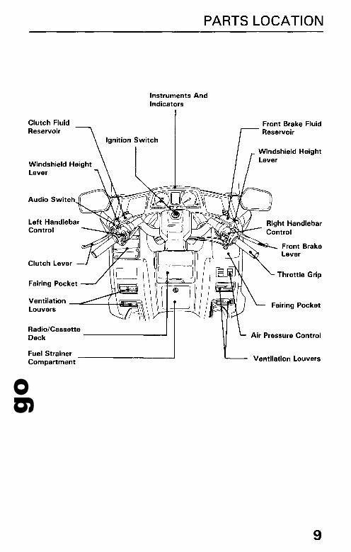
goPARTS LOCATION
Instruments AndIndicators
Clutch FluidReservoir
Ignition Switch
Windshield HeightLever
Audio Switch
Left HandlebarControl
Clutch Lever
Fairing Pocket
Ventilation -...-:::'----+---tlE~Louvers
Radio/CassetteDeck ---------....
Fuel StrainerCompartment
Front Brake FluidReservoir
Front BrakeLever
Throttle Grip
Fairing Pocket
Air Pressure Control
Ventilation Louvers
9

goPARTS LOCATION
Trunk SidePocket
Trunk
Rear BrakeFluid Reservoir
Main Fuse A
Saddlebag
10
Final DriveOil Filler Cap
Main Fuse B
Rear BrakePedal
CoolingFan
Front BrakeCaliper
go
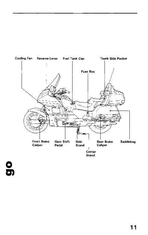
Cooling Fan Reverse Lever Fuel Tank Cap
Fuse Box
Trunk Side Pocket
Front BrakeCaliper
Gear ShiftPedal
SideStand
CenterStand
Rear BrakeCaliper
Saddlebag
11

goPARTS LOCATION
INSTRUMENTS AND INDICATORS
The indicators and warning lights are incorporated in the instrument panel. Their functions are described on the followingpages.
Digital Clock, Air Pressure AndSpeedometer Audio System Display
Tachometer
12
Trip MeterReset Button(page 13)
CoolantTemperatureGauge(page 16)
Fuel Gauge(page 16)
Digital Clockadjust knob(page 15)
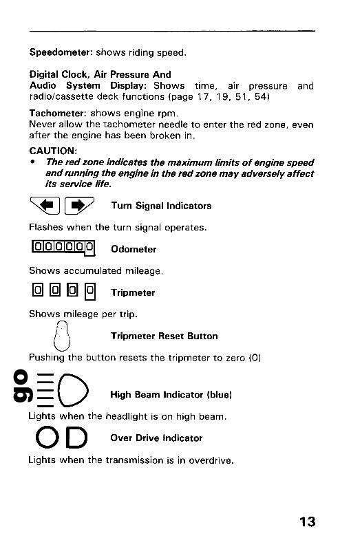
goSpeedometer: shows riding speed.
Digital Clock, Air Pressure AndAudio System Display: Shows time, air pressure andradio/cassette deck functions (page 17, 19, 51, 54)
Tachometer: shows engine rpm.Never allow the tachometer needle to enter the red zone, evenafter the engine has been broken in.
CAUTION:• The red zone indicates the maximum limits of engine speed
and running the engine in the red zone may adversely affectits service life.
Turn Signal Indicators
Flashes when the turn signal operates.
~ Odometer
Shows accumulated mileage.
IQIIQIIQI 19 Tripmeter
Shows mileage per trip.
OJ Tripmeter Reset Button
Pushing the button resets the tripmeter to zero (0)
High Beam Indicator (blue)
Lights when the headlight is on high beam.
00 Over Drive Indicator
Lights when the transmission is in overdrive.
13
goPARTS LOCATION
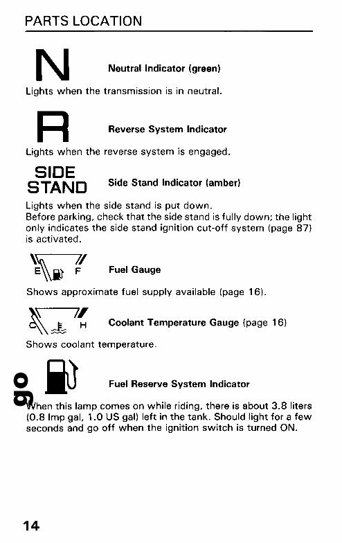
N Neutral Indicator (green)
Lights when the transmission is in neutral.
R Reverse System Indicator
Lights when the reverse system is engaged.
SIDESTAND Side Stand Indicator (amber)
Lights when the side stand is put down.Before parking, check that the side stand is fully down; the lightonly indicates the side stand ignition cut-off system (page 87)is activated.
Fuel Gauge
Shows approximate fuel supply available (page 16).
~\ 71C\\& H
Coolant Temperature Gauge (page 16)
Shows coolant temperature.
Fuel Reserve System Indicator
When this lamp comes on while riding, there is about 3.8 liters(0.8 Imp gal, 1.0 US gal) left in the tank. Should light for a fewseconds and go off when the ignition switch is turned ON.
14

goOil Pressure Warning Light (red)
Cruise Control Set Indicator
Lights when engine oil pressure is below the normal operatingrange. Should light when the ignition switch is ON and theengine is not running. Should go off when engine starts, except for occasional flickering at or near idling speed whenengine is warm.
CAUTION:• Running the engine with insufficient oilpressure may cause
serious engine damage.
CRUISESET
Lights when the cruise control set switch is pushed on (page36).Should also light for a few seconds and then go off when the ignition switch is turned ON.
BI!III• The cruise control automates the function of the throttle;
do not operate the cruise control while in traffic, on windingroads or in bad weather conditions.
CRUISEON
Cruise Control Master Switch Indicator
Digital Clock Adjust Knob
Lights when the cruise control master switch is pushed on(page 36).Should also light for a few seconds and then go off when the ignition switch is turned ON.
~H
To adjust the hour, turn and hold the knob to H.To adjust minutes, turn and hold the knob to M (page 17).
15

goPARTS LOCATION
Fuel Gauge
The fuel gauge shows the approximate fuel supply available.At F (Full) there are 24.0 liters (5.3 Imp gal, 6.3 US gal), including the reserve supply.When the gauge needle enters the red band, fuel will be lowand you should refill the tank as soon as possible. The amountof fuel left in the tank when the needle enters the red band isapproximately 3.6 liters (0.8 Imp gal, 0.9 US gal).
Red Band
Needle ------.......//F
Coolant Temperature Gauge
When the needle begins to move above the C (Cold) mark, theengine is warm enough for the motorcycle to be ridden. Thenormal operating temperature range is within the section between the Hand C marks. If the needle reaches the H (Hot)mark, stop the engine and check the reserve tank coolant level(page 24).Read page 24- 25 and do not ride the motorcycle until the problem has been corrected.
CAUTION:• Exceeding maximum operating temperature may cause
serious engine damage.
Needle--...........
16
71H

goDigital Clock
Shows the hour and minutes. To adjust time, proceed asfollows:H (Hour) - Turn and hold the adjust knob to H.M (Minute) - Turn and hold the adjust knob to M.
Display
Adjust Knob (page 12)
, =, .•-, .-,f"·LfLft T
Hour Minute
17
goMAJOR COMPONENTS(Information you need to operate this motorcycle)
!lImB• If the Pre-ride Inspection (page 61) is not performed, severe
personal injury or vehicle damage may result.
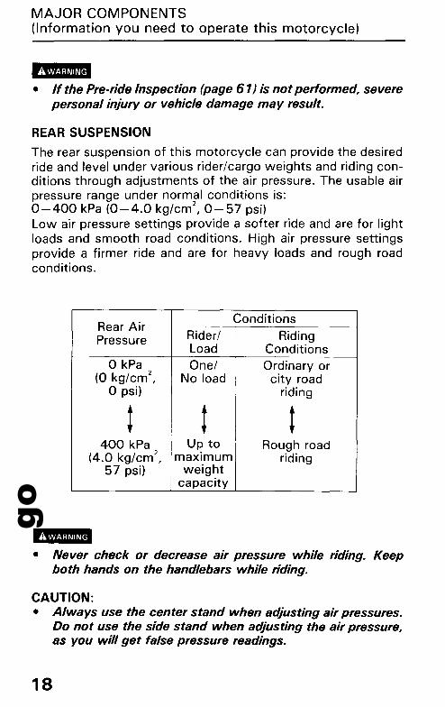
REAR SUSPENSION
The rear suspension of this motorcycle can provide the desiredride and level under various rider/cargo weights and riding conditions through adjustments of the air pressure. The usable airpressure range under normal conditions is:0-400 kPa (0-4.0 kg/cm 2
, 0-57 psi)Low air pressure settings provide a softer ride and are for lightloads and smooth road conditions. High air pressure settingsprovide a firmer ride and are for heavy loads and rough roadconditions.
Rear AirConditions
Pressure Rider/ RidingLoad Conditions
o kPa One/ Ordinary or(0 kg/cm2
, No load city roado psi) riding
t t t400 kPa Up to Rough road
(4.0 kg/cm2, maximum riding
57 psi) weightcapacity
BI!III• Never check or decrease air pressure while riding. Keep
both hands on the handlebars while riding.
CAUTION:• Always use the center stand when adjusting air pressures.
Do not use the side stand when adjusting the air pressure,as you will get false pressure readings.
18
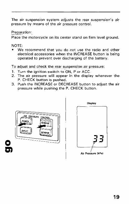
goThe air suspension system adjusts the rear suspension's airpressure by means of the air pressure control.
Preparation:
Place the motorcycle on its center stand on firm level ground.
NOTE:• We recommend that you do not use the radio and other
electrical accessories when the INCREASE button is beingoperated to prevent over discharging of the battery.
To adjust and check the rear suspension air pressure:
1. Turn the ignition switch to ON, P or ACC.2. The air pressure will appear in the display whenever the
P. CHECK button is pushed.3. Push the INCREASE or DECREASE button to adjust the air
pressure while pushing the P. CHECK button.
Display
~SSURE CONTROL
~(~ -, -,
-:. ~.r-/
Air Pressure (kPa)
19
goMAJOR COMPONENTS(Information you need to operate this motorcycle)
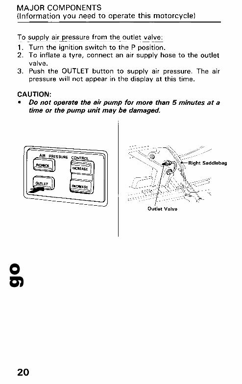
To supply air pressure from the outlet valve:
1. Turn the ignition switch to the P position.2. To inflate a tyre, connect an air supply hose to the outlet
valve.3. Push the OUTLET button to supply air pressure. The air
pressure will not appear in the display at this time.
CAUTION:• Do not operate the air pump for more than 5 minutes at a
time or the pump unit may be damaged.
~AIR PRESSURE CONTROL
P.OlECKINCRE4SE
Outlet Valve
20

goBRAKES
Both front and rear brakes are hydraulic disc types.As the brake pads wear, the brake fluid level drops,automatically compensating for wear. There are no adjustments to perform, but fluid level and pad wear must be inspected periodically. The system must be inspected frequentlyto ensure there are no fluid leaks. If the control lever or pedalfree travel becomes excessive and the brake pads are not wornbeyond the recommended limit (page 95), there is probably airin the brake system and it must be bled. See your authorizedHonda dealer for this service.
Brake Fluid Level:
!BIll• Brake fluid may cause irritation. A void contact with skin or
eyes. In case of contact, flush thoroughly with water andcall a doctor if your eyes were exposed.
Brake fluid must be added to the reservoir whenever the fluidlevel begins to reach the lower level mark.Fill the reservoir with DOT 4 BRAKE FLUID from a sealed container up to the upper level mark. Reinstall the removed parts inthe reverse order of removal. Tighten the screws securely.
FRONT
21

goMAJOR COMPONENTS(Information you need to operate this motorcycle)
REAR
CAUTION:• Handle brake fluid with care because it can damage plastic
and painted surfaces.• When adding brake fluid, be sure the reservoir is horizontal
before the cap is removed or brake fluid may spill out.• Use only DOT 4 brake fluid from a sealed container.• Never allow contaminants such as dirt or water to enter the
brake fluid reservoir.
Other Checks:
Make sure there are no fluid leaks. Check for deterioration orcracks in the hoses and fittings.
22

goCLUTCH
This motorcycle has a hydraulically actuated clutch. There areno adjustments to perform but the clutch system must be inspected periodically for fluid level and leakage. If the controllever freeplay becomes excessive and the motorcycle creeps orstalls when shifted into gear, or if the clutch slips, causing acceleration to lag behind engine speed, there is probably air inthe clutch system and it must be bled out. See you authorizedHonda dealer for this service.
Fluid level:
Check that the fluid level is above the LOWER level mark withthe motorcycle in an upright position. If the fluid level is nearthe LOWER level mark, it indicates fluid leakage. See yourauthorized Honda dealer.
Other Checks:
Make sure there are no fluid leaks. Check for deterioration orcracks in the hose and fittings.
Clutch reservoir
LOWER Level
23
goMAJOR COMPONENTS(Information you need to operate this motorcycle)
COOLANT
Coolant Recommendation
The owner must properly maintain the coolant to prevent freezing, overheating, and corrosion. Use only high quality ethyleneglycol antifreeze containing corrosion protection inhibitorsspecifically recommended for use in aluminum engines. (SEEANTIFREEZE CONTAINER LABEl).
CAUTION:• Use only low-mineral drinking water or distilled water as a
part of the antifreeze solution. Water that is high in mineralcontent or salt may be harmful to the aluminum engine.
The factory provides a 50/50 s'olution of antifreeze and waterin this motorcycle. This coolant solution is recommended formost operating temperatures and provides good corrosion protection. A higher concentration of antifreeze decreases thecooling system performance and is recommended only whenadditional protection against freezing is needed. A concentration of less than 40/60 (40% antifreeze) will not provide propercorrosion protection. During freezing temperatures, check thecooling system frequently and add higher concentrations of antifreeze (up to a maximum of 60% antifreeze) if required.
24

goInspection
Check the coolant level in the reserve tank while the engine isat the normal operating temperature with the motorcycle in anupright position. If the coolant level is below the lower levelmark, remove the reserve tank cap and add coolant mixtureuntil it reaches the upper level mark. Do not remove theradiator cap.
l.-• Do not remove the radiator cap when the engine is hot. The
coolant is under pressure and could scald you.• Keep hands and clothing away from the cooling fan, as it
starts atltomatically.
If the reserve tank is empty, or if coolant loss is excessive,check for leaks and see your authorized Honda dealer forrepair.
Reserve TankDipstick
Upper
Lower
25
goMAJOR COMPONENTS(Information you need to operate this motorcycle)
FUEL
Automatic Fuel ON-OFF
Fuel will flow to the carburetors only when the engine is startedor is running. A check valve in the fuel pump shuts off fuel flowwhen the engine is turned off.
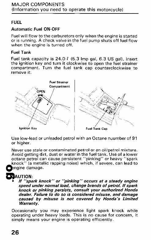
Fuel Tank
Fuel tank capacity is 24.0 f (5.3 Imp gal, 6.3 US gal). Insertthe ignition key and turn it clockwise to open the fuel strainercompartment. Turn the fuel tank cap counterclockwise toremove it.
Ignition Key
Fuel StrainerCompartment
Fuel Tank Cap
Use low-lead or unleaded petrol with an Octane nuumber of 91or higher.
Never use stale or contaminated petrol or an oil/petrol mixture.Avoid getting dirt, dust or water in the fuel tank. Use of a loweroctane petrol can cause persistent "pinking" or heavy "sparkknock" (a metallic rapping noise) which, if severe, can lead toengine damage.
CAUTION:• If "spark knock" or "pinking" occurs at a steady engine
speed under normal load, change brands ofpetrol. If sparkknock or pinking persists, consult your authorized Hondadealer. Failure to do so is considered misuse, and damagecaused by misuse is not covered by Honda's LimitedWarranty.
Occasionally you may experience light spark knock whileoperating under heavy loads. This is no cause for concern, itsimply means your engine is operating efficiently.
26
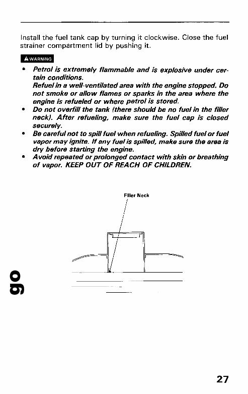
goInstall the fuel tank cap by turning it clockwise. Close the fuelstrainer compartment lid by pushing it.
IBIII• Petrol is extremely flammable and is explosive under cer
tain conditions.Refuel in a well-ventilated area with the engine stopped. Donot smoke or allow flames or sparks in the area where theengine is refueled or where petrol is stored.
• Do not overfill the tank (there should be no fuel in the fillerneck). After refueling, make sure the fuel cap is closedsecurely.
• Be careful not to spill fuel when refueling. Spilled fuel or fuelvapor may ignite. If any·fuel is spilled, make sure the area isdry before starting the engine.
• A void repeated or prolonged contact with skin or breathingof vapor. KEEP OUT OF REACH OF CHILDREN.
Filler Neck
27
goMAJOR COMPONENTS(Information you need to operate this motorcycle)
Petrol Containing Alcohol
If you decide to use a petrol containing alcohol (gasohol), besure it's octane rating is at least as high as that recommendedby Honda. There are two types of "gasohol": one containingethanol, and the other containing methanol. Do not usegasohol that contains more than 100/0 ethanol. Do not usepetrol containing methanol (methyl or wood alcohol) that doesnot also contain cosolvents and corrosion inhibitors formethanol. Never use petrol containing more than 5%methanol, even if it has cosolvents and corrosion inhibitors.
NOTE:• Fuel system damage or engine performance problems
resulting from the use of fuels that contain alcohol is notcovered under the warranty. Honda cannot endorse the useof fuels containing methanol since evidence of theirsuitability is as yet incomplete.
• Before buying fuel from an unfamiliar station, try to find outthe fuel contains alcohol, if it does, confirm the type andpercentage of alcohol used. If you notice any undesirableoperating symptoms while using a petrol that containsalcohol, or one that you think contains alcohol, switch to apetrol that you know does not contain alcohol.
28

goENGINE OILEngine Oil Level Check
Check engine oil level each day before riding the motorcycle.The level must be maintained between the upper and lowerlevel marks on the dipstick.
1. Place the motorcycle on its center stand on firm, levelground and remove the front right side cover.
2. Start the engine and let it idle for a few minutes. Make surethe red oil pressure warning light goes off. If the light remains on, stop the engine immediately.
3. Stop the engine. After a few minutes, remove the dipstickand wipe it clean, then reinsert the dipstick without screwing it in.The oil level should be between the upper and lower levelmarks on the dipstick.
4. If required, remove the filler cap, add the specified oil up tothe upper level mark (page 79). DO' not overfill.
5. Reinstall the filler cap, dipstick, and front right side cover.Check for oil leaks.
CAUTION:• Running the engine with insufficient oil can cause serious
engine damage.
Dipstick
Filler Cap
29

goMAJOR COMPONENTS(Information you need to operate this motorcycle)
FINAL DRIVE OIL
Oil Level Check
Check the final drive oil level when specified by themaintenance schedule.1. Place the motorcycle on its center stand on firm, level
ground.2. Remove the oil filler cap.3. Check that the oil level reaches the lower edge of the oil
cap hole.
NOTE:• If the level is low, check for leaks. Pour fresh oil through
the oil filler hole until it reaches the lower edge of theopening.
Recommended Oil: HYPOID GEAR OIL SAE 80
Oil Filler Cap
@jge
30
goTUBELESS TYRESThis motorcycle is equipped with tubeless tyres, valves, andwheel rims. Use only tyres marked "TUBELESS" and tubelessvalves on rims marked "TUBELESS TYRE APPLICABLE."Proper air pressure will provide maximum stability, riding comfort and tyre life. Check tyre pressure frequently and adjust ifnecessary.
Never mount tires designed for use on automobiles on a motorcycle rim.
!BIll• Any attempt to mount passenger car tires on a motorcycle
rim may cause the tire bead to separate from the rim withenough explosive force to cause serious injury or death.
NOTE:• Tyre pressure should be checked before you ride while the
tyres are"cold."• Tubeless tyres have some degree of self-sealing ability if
they are punctured, and leakage is often very slow. Inspectvery closely for punctures, especially if the tyre is not fullyinflated.
Check the tyres for cuts, imbedded nails or other sharp objects. Check the rims for dents or deformation. If there is anydamage, see your authorized Honda dealer for repair, replacement, and balancing.
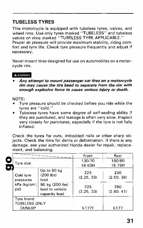
Front Rear
Tyre size130/70 160/801863H 1675H
Up to 90 kg225 250
Cold tyre (200Ibs)(2.25,33) (2.50,36)
pressures loadkPa (kg/cm 2 , 90 kg (200 Ibs)
225 280psi) load to vehicle(2.25,33) (2.80,41 )
capacity loadTyre brandTUBELESS ONLY
DUNLOP K177F K177
31

goMAJOR COMPONENTS(Information you need to operate this motorcycle)
DIIII• Improper tyre inflation will cause abnormal tread wear and
create a safety hazard. Underinflation may result in the tyreslipping on, or coming off of the rim causing tyre deflationthat may result in a loss of vehicle control.
• Operation with excessively worn tyres is hazardous andwill adversely affect traction and handling.
Replace tyres before tread depth at the center of the tyrereaches the following limit or when the surface is flush with thewear indicators.
Minimum tread depth
Front: 1.5 mm (0.06 in)Rear: 2.0 mm (0.08 in)
WearIndicator
I--t--- Wear IndicatorLocation Mark
32
goTyre Repair/Replacement:
See your authorized Honda Dealer.
Il!Imm• The use of tyres other than those listed on the tyre informa
tion label may adversely affect handling.• Do not install tube-type tyres on tubeless rims. The beads
may not seat and the tyres could slip on the rims, causingtyre deflation that may result in a loss of vehicle control.
• Do not install a tube inside a tubeless tyre. Excessive heatbuild-up may cause the tube to burst resulting in rapid tyredeflation that may result in a loss of vehicle control.
• Proper wheel balance is necessary for safe, stable handlingof the motorcycle. Do not remove or change any wheelbalance weights. When wheel balancing is required, seeyour authorized Honda dealer. Wheel balancing is requiredafter tyre repair or replacement.
• To avoid possible repair failure and tyre deflation that mayresult in a loss of vehicle control, do not exceed 80 km/h(50 mph) for the first 24 hours, or 130 km/h (80 mph) atany time, after tyre repair.
• Replace the tyre if the sidewall is punctured or damaged.Sidewall flexing may cause repair failure and tyre deflationthat may result in a loss of vehicle control.
CAUTION:• Do not try to remove tubeless tyres without special tools
and rim protectors. You may damage the rim sealing surface or disfigure the rim.
33

goESSENTIAL INDIVIDUAL COMPONENTS
IGNITION SWITCH
The ignition switch is on the handlebar cover.
Key Function KeyPosition Removal
All electrical circuits closed. Key cannotON Engine and lights can be
operated. be removed.
ACCAll electrical circuits are off except Key cannotfor the ACC circuit. be removed.
OFF All electrical circuits are off. Key can beEngine cannot be started. removed.For parking the motorcycle neartraffic. The taillight, position light,licence light and ACC circuit are on; Key can beP (parking) but the other lights are off. The rear removed.suspension air pressure can beoperated. The engine cannot bestarted.
LOCK Steering is locked. Engine and lights Key can be(steeringlock) cannot be operated. removed.
34
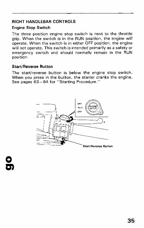
goRIGHT HANDLEBAR CONTROLS
Engine Stop Switch
The three position engine stop switch is next to the throttlegrip. When the switch is in the RUN position, the engine willoperate. When the switch is in either OFF position, the enginewill not operate. This switch is intended primarily as a safety oremergency switch and should normally remain in the RUNposition.
Start/Reverse Button
The start/reverse button is below the engine stop switch.When you press in the button, the starter cranks the engine.See pages 63 - 64 for "Starting Procedure."
OFF
Start/Reverse Button
35
goESSENTIAL INDIVIDUAL COMPONENTS
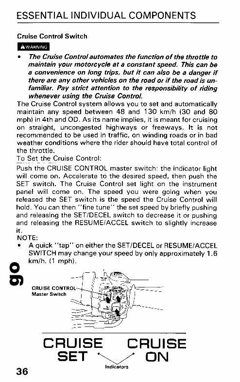
Cruise Control Switch-• The Cruise Control automates the function of the throttle tomaintain your motorcycle at a constant speed. This can bea convenience on long trips, but it can also be a danger ifthere are any other vehicles on the road or if the road is unfamiliar. Pay strict attention to the responsibility of ridingwhenever using the Cruise Control.
The Cruise Control system allows you to set and automaticallymaintain any speed between 48 and 130 km/h (30 and 80mph) in 4th and OD. As its name implies, it is meant for cruisingon straight, uncongested highways or freeways. It is notrecommended to be used in traffic, on winding roads or in badweather conditions where the rider should have total control ofthe throttle.To Set the Cruise Control:
Push the CRUISE CONTROL master switch: the indicator lightwill come on. Accelerate to the desired speed, then push theSET switch. The Cruise Control set light on the instrumentpanel will come on. The speed you were going when youreleased the SET switch is the speed the Cruise Control willhold. You can then "fine tune" the set speed by briefly pushingand releasing the SET/DECEL switch to decrease it or pushingand releasing the RESUME/ACCEL switch to slightly increaseit.NOTE:• A quick "tap" on either the SET/DECEL or RESUME/ACCEL
SWITCH may change your speed by only approximately 1.6km/h. (1 mph).
CRUISE CONTROLMaster Switch
36
CRUISE CRUISESET~ ON
Indicators
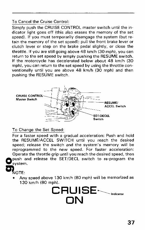
goTo Cancel the Cruise Control:
Simply push the CRUISE CONTROL master switch until the indicator light goes off (this also erases the memory of the setspeed). If you must temporarily disengage the system (but retain the memory of the set speed); pull the front brake lever orclutch lever or step on the brake pedal slightly, or close thethrottle. If you are still going above 48 km/h (30 mph), you canreturn to the set speed by simply pushing the RESUME switch.If the motorcycle has decelerated below about 48 km/h (30mph), you can return to the set speed by using the throttle conventionally until you are above 48 km/h (30 mph) and thenpushing the RESUME switch.
CRUISE CONTROLMaster Switch
V~mntt-+----RESUMEI
11 -°_ ACCEL Switch
SET/OECELSwitch
To Change the Set Speed:
For a faster speed with a gradual acceleration: Push and holdthe RESUME/ACCEL SWITCH until you reach the desiredspeed; release the switch and the system's memory will bereprogrammed to the new speed. For faster acceleration:Operate the throttle grip until you reach the desired speed, thenpush and release the SET/DECL switch to re-program thesystem.
NOTE:• Any speed above 130 km/h (80 mph) will be memorized as
130 km/h (80 mph).
C R U IS E -----Indicator
ON
37

goESSENTIAL INDIVIDUAL COMPONENTS
To change to a slower speed: Push and hold the SET/DECELswitch and the motorcycle will slow down; when you reach thedesired slower speed, release the switch and the system will bereprogrammed. For temporary acceleration above the setspeed, such as for passing, use the throttle conventionally.When you want to return to the set speed, close the throttleand coast without applying the brakes.
NOTE:• With the Cruise Control on, your speed will still vary
slightly, particularly going up or down hills.
38
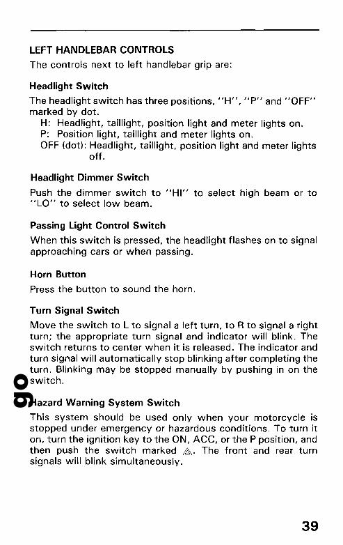
goLEFT HANDLEBAR CONTROLS
The controls next to left handlebar grip are:
Headlight Switch
The headlight switch has three positions, IIH", IIplI and 1I0FF"marked by dot.
H: Headlight, taillight, position light and meter lights on.P: Position light, taillight and meter lights on.OFF (dot): Headlight, taillight, position light and meter lights
off.
Headlight Dimmer Switch
Push the dimmer switch to IIHI" to select high beam or toIILO" to select low beam.
Passing Light Control Switch
When this switch is pressed, the headlight flashes on to signalapproaching cars or when passing.
Horn Button
Press the button to sound the horn.
Turn Signal Switch
Move the switch to L to signal a left turn, to R to signal a rightturn; the appropriate turn signal and indicator will blink. Theswitch returns to center when it is released. The indicator andturn signal will automatically stop blinking after completing theturn. Blinking may be stopped manually by pushing in on theswitch.
Hazard Warning System Switch
This system should be used only when your motorcycle isstopped under emergency or hazardous conditions. To turn iton, turn the ignition key to the ON, ACC, or the P position, andthen push the switch marked ~. The front and rear turnsignals will blink simultaneously.
39

goESSENTIAL INDIVIDUAL COMPONENTS
CAUTION:• Be sure to turn the switch off when the hazard warning is
no longer required, or the turn signals will not work properly, and may confuse other drivers.
HeadlightDimmer Switch
Horn Button --~
Hazard WarningSystem Switch
HeadlightSwitch
40
goFEATURES (Not required for operation)
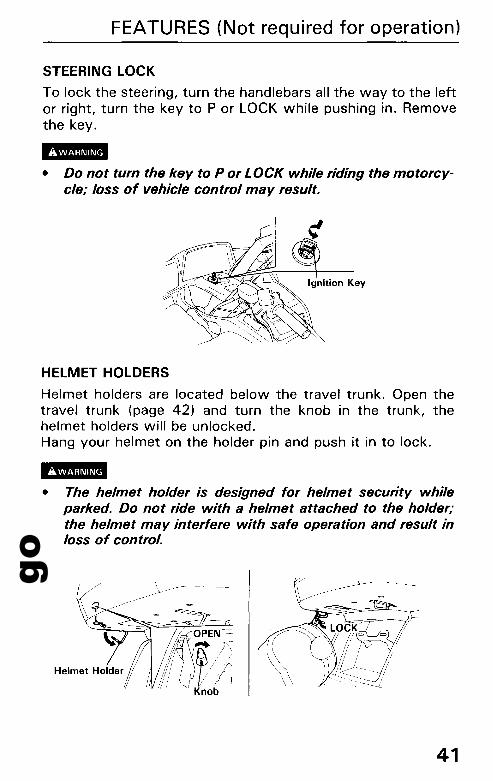
STEERING LOCK
To lock the steering, turn the handlebars all the way to the leftor right, turn the key to P or LOCK while pushing in. Removethe key.
!BIll• Do not turn the key to P or LOCK while riding the motorcy
cle; loss of vehicle control may result.
HELMET HOLDERS
Helmet holders are located below the travel trunk. Open thetravel trunk (page 42) and turn the knob in the trunk, thehelmet holders will be unlocked.Hang your helmet on the holder pin and push it in to lock.
!BIll• The helmet holder is designed for helmet security while
parked. Do not ride with a helmet attached to the holder;the helmet may interfere with safe operation and result inloss of control.
-~------I. ~---------
41

goFEATURES (Not required for operation)
TRAVEL TRUNK AND SADDLEBAGS
To open the travel trunk with the ignition key:
Insert the ignition key and turn it counterclockwise. The trunkcan be opened without the latch.Close the trunk lid and make sure the trunk is locked.
To open the travel trunk with the latch:
Insert the ignition key and turn it clockwise. Pull down the middle latch lever to open the trunk.To lock the trunk, close the trunk lid and turn the ignition keycounterclockwise. Make sure the trunk is locked.
IlBIII• The travel trunk is for lightweight items. Do not carry more
than 9 kg (20 Ibs). Excessive weight may adversely affectvehicle handling and control.
• Review Loading and Accessories before loading (page 6).
OPEN
Ignition Key
42
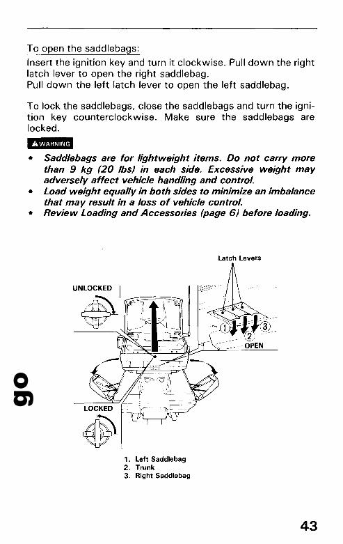
goTo open the saddlebags:
Insert the ignition key and turn it clockwise. Pull down the rightlatch lever to open the right saddlebag.Pull down the left latch lever to open the left saddlebag.
To lock the saddlebags, close the saddlebags and turn the ignition key counterclockwise. Make sure the saddlebags arelocked.
II'I!B• Saddlebags are for lightweight items. Do not carry more
than 9 kg (20Ibs) in each side. Excessive weight mayadversely affect vehicle handling and control.
• Load weight equally in both sides to minimize an imbalancethat may result in a loss of vehicle control.
• Review Loading and Accessories (page 6) before loading.
Latch Levers
UNLOCKED
~
1. Left Saddlebag2. Trunk3. Right Saddlebag
43
goFEATURES (Not required for operation)
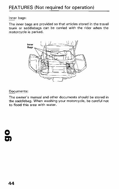
Inner bags:
The inner bags are provided so that articles stored in the traveltrunk or saddlebags can be carried with the rider when themotorcycle is parked.
InnerBags
Documents:
The owner's manual and other documents should be stored inthe saddlebag. When washing your motorcycle, be careful notto flood this area with water.
44

goAlternate method to open the saddlebag:
If a saddlebag becomes jammed and will not open by its rearlatch lever:1. Open the travel trunk and remove the plug from the right or
left access hole in the floor of the trunk.2. Put your finger through the access hole and push down the
rod to open the saddlebag.
45

goFEATURES (Not required for operation)
FAIRING POCKETS
The left fairing pocket can be used by unsnapping the cover. Toremove the right pocket lid, insert the ignition key, turn itclockwise and open the lid.To attach the right pocket lid, slide the prong at the front of thelid into the slot in the fairing pocket, then push the other end ofthe lid down until it locks.-• Fairing pockets are for lightweight items. Do not carry more
than 2 kg (5Ibs) in each side.Excessive weight may adversely affect vehicle handlingand control.
• Load weight equally in both sides to avoid an imbalancethat may result in a loss of vehicle control.
• Review Loading and Acccessories before loading (page 6).
Ignition Key
46
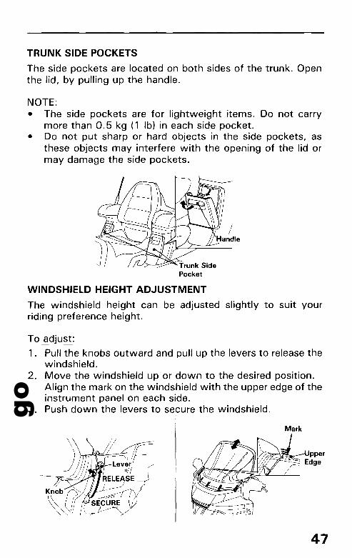
goTRUNK SIDE POCKETS
The side pockets are located on both sides of the trunk. Openthe lid, by pulling up the handle.
NOTE:• The side pockets are for lightweight items. Do not carry
more than 0.5 kg (1 Ib) in each side pocket.• Do not put sharp or hard objects in the side pockets, as
these objects may interfere with the opening of the lid ormay damage the side pockets.
WINDSHIELD HEIGHT ADJUSTMENT
The windshield height can be adjusted slightly to suit yourriding preference height.
To adjust:
1. Pull the knobs outward and pull up the levers to release thewindshield.
2. Move the windshield up or down to the desired position.Align the mark on the windshield with the upper edge of theinstrument panel on each side.
3. Push down the levers to secure the windshield.
Mark
f ' -~q::c""==L:::::e~vJlr(-
11/!
R~LEASEKnobj;j, ~
~01 i~RE
47

goFEATURES (Not required for operation)
HEADLIGHT BEAM ADJUSTMENT
The headlight beam can be raised or lowered by turning the vertical beam adjusting knob. Obey local laws and regulations concerning headlight adjustment.-• Do not adjust the headlight beam while riding the motorcy-
cle. Operating the motorcycle with one or both hands awayfrom the handlebar/controls may result in a loss of vehiclecontrol.
Adjusting Knob
VENTILATION LOUVERS
This motorcycle has upper and lower ventilation louvers. Openthe upper louvers to direct fresh air. Open the lower louvers andadjust the levers to direct fresh or warmed air. For additionallower air flow, optional louvers can be mounted at the engineguards.-• Do not adjust the ventilation louvers while riding the
motorcycle. Operating the motorcycle with one or bothhands away from the handlebar/controls may result in aloss of vehicle control.
UPPER
48
LOWER
~\
¥:~\\ .....\, FR.ES'H\~I ...~~~~ I,'
( \WARMI ~
Le~er
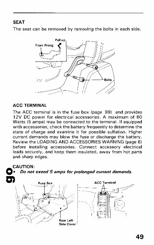
goSEAT
The seat can be removed by removing the bolts in each side.
Pull up
Front Prong -<
W
ACC TERMINAL
The ACC terminal is in the fuse box (page 99) and provides12V DC power for electrical accessories. A maximum of 60Watts (5 amps) may be connected to the terminal. If equippedwith accessories, check the battery frequently to determine thestate of charge and examine it for possible sulfation. Highercurrent demands may blow the fuse or discharge the battery.Review the LOADING AND ACCESSORIES WARNING (page 6)before installing accessories. Connect accessory electricalleads securely, and keep them insulated, away from hot partsand sharp edges.
CAUTION:• Do not exeed 5 amps for prolonged current demands.
\
\,
ACC Terminal
49
goFEATURES (Not required for operation)
PROTECTION AGAINST WATER
The radio/cassette deck is designed to be weather proof.However, it is not designed to be sprayed directly with a hose.
CAUTION:• When washing the motorcycle, avoid spraying high
pressure water (typical in coin-operated car washes) nearthe audio system.
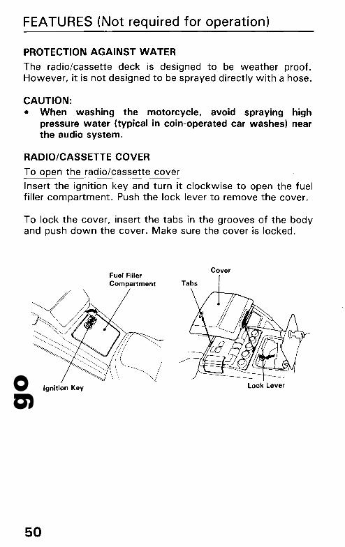
RADIO/CASSETTE COVER
To open the radio/cassette cover
Insert the ignition key and turn it clockwise to open the fuelfiller compartment. Push the lock lever to remove the cover.
To lock the cover, insert the tabs in the grooves of the bodyand push down the cover. Make sure the cover is locked.
Fuel FillerCompartment Tabs
Cover
Ignition Key
50
Lock Lever

goDISPLAY LEFT HANDL~BAR CONTROLS
'$"1'#1 AMB.
AM' I~' C' S'ST.' C. Lt.L
'~'·t,r,fe·L.fLt
Search Lever/TapeProgram DirectionSelector
Muting Switch
RADIO/CASSETTE DECK
Radio/CassetteButton
Headset/Speaker ModeButson
Ambience Button
Channel Button
Ic==-Hl-+4-f- Memory Button~-------------'
AM/FM Band -+--+--+-i----H-+~
Button
Tone ControlKnob
"----- Intercom Mute Knob
,r-------Hf+- Fast-forward AndRewinding Button
r------l-H- Auto Volume
'[;~~~~~~~~~~~~-~-;Z-~~I-~-i-~:J' Control Knob
Cassette Lid --1---+--+-+-
Eject Button
'-----Intercom Volume Knob
51
goFEATURES (Not required for operation)
AM/FM RADIO
The radio can be used with the ignition switch at ACC, ON or P.
Power Switch/Volume Control KnobWhen this knob is turned clockwise, power is applied to theradio, and the display indicates"AM" or "FM." Turning theknob further increases the volume. If the display does not show"AM" or "FM," the radio/cassette button is in the TAPEmode. To play the radio, push this switch.
AM/FM Band Button
To receive FM signals, push this button. To set to AM, pushthis button again. The"AM" or "FM" and "ST" (stereo signalreception only) will be visible in the display. "ST" lights upwhen an FM station in stereo is being received. As FM stereoreception becomes weaker, special circuits in the radio gradually blend the sound toward mono to maintain some sound quality, even though the ST indicator remains ON. Stereo receptionis available only for FM stereo broadcasts, not for AM.
Preset Stations
You can preset six AM stations and six FM stations. AM andFM stations are preset as follows:1. Find the station you wish by the search lever (page 53).2. Push the M button and the memory indicator "CH" will
blink in the display.3. Push the CH (channel) button and select a channel you
wish, then push the M button again while the memory indicator "CH" is blinking. The indicator will stop blinkingand the preset channel will be visible in the display. Thememory indicator will go off 7 seconds after the M buttonwas pushed, if the M button was not pushed again.
4. The memory is erased automatically if you tune and preseta new AM or FM station.
52

goSearch Lever
You can find the station you wish by the search lever. Whenthe lever is pushed up, the frequency moves up, and when thelever is pushed down, it moves down.If the lever is depressed once, the AM frequency displaymoves in 9 kHz steps and the FM frequency in 50 kHz.In auto search, release the lever after the frequency displaymoves, and the next station is automatically tuned in. Repeatthe above steps until the desired station is tuned in.When the frequency display comes to either end, transition tothe other end of the band takes place and continues in thesame direction.
Muting Switch
Switching the Mute switch ON instantly lowers the radio'svolume so you may hear surrounding sound more clearly. Thedisplay will indicate "MUTE." Switching Mute OFF restoresthe original volume. The muting functions for the radio andcassette deck.
IBII• While riding, never:
• Adjust the volume control.• Switch between radio and cassette• Install or remove cassette tape
Keep both hands on the handlebars while riding.• Do not turn up the volume so loud that emergency vehicles
or traffic cannot be heard.
SearchLever Indicator
+
MUTE
53

goFEATURES (Not required for operation)
CASSETTE DECK
Loading
Push the eject button to open the cassette lid and slide the tapeinto the deck, following the inserting direction shown on thelid.
CAUTION:
• Check there is no slack in the tape before inserting thecassette tape into the deck.
• Make sure the lid is secured after inserting the cassettetape into the deck.
• Do not open the casette lid in the rain. Before opening thecassette lid, wipe offany dirt or water on the outer surface.
• The use of 120-minute cassette tapes is not recommended.If necessary to use 120-minute tapes, do not switch thetape operation mode frequently. Most 120-minute tapestretches easily and can become tangled in the playermechanism.
Eject Button
The cassette is ejected from the deck when this button isdepressed.
Inserting Direction
54

goTape player Maintenance
The head in the cassette tape player can pick up dirt or tapedeposits each time a cassette is played. The result is low orII muddy" sound from one or both channels, as if the trebletone control were turned all the way down. To prevent this,you should periodically clean the head with a commerciallyavailable cleaning cassette.As preventive maintenance, clean the head about every 30hours of use. If you wait until the head becomes very dirty(noticeably poor sound), it may not be possible to remove alldeposits with a simple cleaning cassette.
CAUTION:• Storing cassettes out of their cases, or touching the
magnetic tape with your fingers will increase the amount ofdirt that gets to the tape head. Using low-quality "offbrand" tape will increase the amount of tape deposits thatget on the head. Both of these practices may eventuallylead to damage of the head and playing mechanism.
Power Switch/Volume Control Knob
When this button is turned clockwise, power is applied to theradio, and display indicates IIAM" or "FM". Then push theradio/cassette button to hear the cassette tape. The display willbe changed to II I,iW "or "w:I " when the deck is loaded with atape. Turning the knob further increases the volume.
Power SwitchlVolume Control Knob
VOLRadio/Cassette button
l~J/tAA
55

goFEATURES (Not required for operation)
Tape Program Direction Selector (PRO)
This switch can be used to change the direction of the tape.The indicator in the display will be changed to the following.This switch can be also used to stop the fast winding.
Tape Program Direction Selector (PRO) Indicators
~I~dic~te theI...7 directionOR
L-t-JFast-forward And Rewinding Buttons
This deck features auto-reverse play I so that both sides of thetape can be played continuously I without turning the cassetteover.Push either button to fast-forward or rewind depending on thecorrect direction of the tape indicated by the arrows on thedisplay. The indicator blinks during fast winding. Push theprogram selector (PRO) to stop the tape.
Fast-forward And Rewinding Buttons
56
BToward left
EJToward right

goAmbience button (AMB)
The"ambience" circuit blends and boosts certain frequenciesfrom both channels, for a "live performance" effect. To usethe circuit, push the AMB button until"AMB." appears in thedisplay. AMB is usable for stereo programs from both tape andFM. The ambience circuit, however, may weak FM stereosignals or poorly recorded tapes sound worse.
Ambience Button
AMBIndicator
AMB.
57
goFEATURES (Not required for operation)
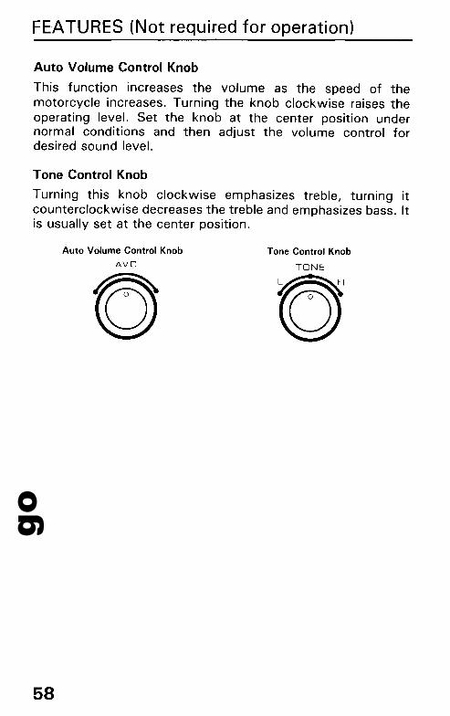
Auto Volume Control Knob
This function increases the volume as the speed of themotorcycle increases. Turning the knob clockwise raises theoperating level. Set the knob at the center position undernormal conditions and then adjust the volume control fordesired sound level.
Tone Control Knob
Turning this knob clockwise emphasizes treble, turning itcounterclockwise decreases the treble and emphasizes bass. Itis usually set at the center position.
58
Auto Volume Control Knob
AveTone Control Knob
TONE
©
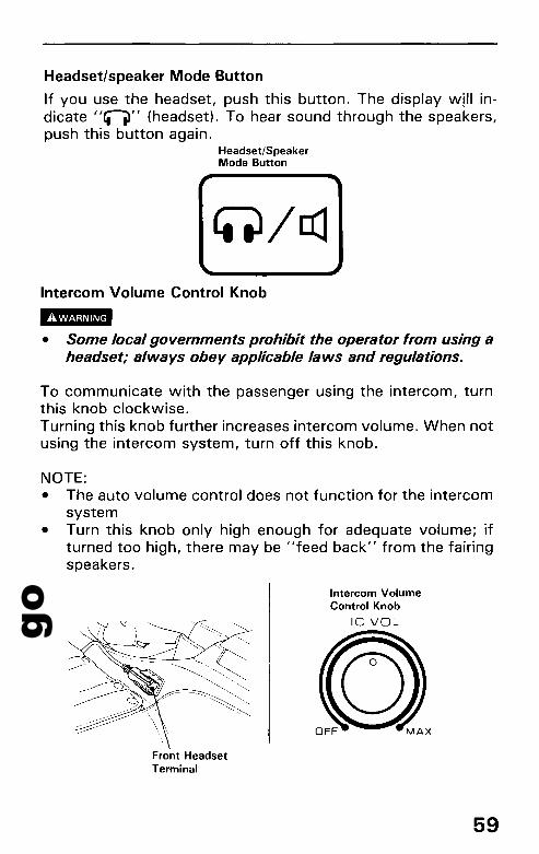
goHeadset/speaker Mode Button
If you use the headset, push this button. The display wi" indicate "fiI)" (headset). To hear sound through the speakers,push this button again.
Headset/SpeakerMode Button
Intercom Volume Control Knob---• Some local governments prohibit the operator from using aheadset; always obey applicable laws and regulations.
To communicate with the passenger using the intercom, turnthis knob clockwise.Turning this knob further increases intercom volume. When notusing the intercom system, turn off this knob.
NOTE:• The auto volume control does not function for the intercom
system• Turn this knob only high enough for adequate volume; if
turned too high, there may be "feed back" from the fairingspeakers.
Intercom VolumeControl Knob
Ie VOL
Front HeadsetTerminal
59

goFEATURES (Not required for operation)
Intercom Mute Knob
The intercom mute system automatically lowers themusic/program volume when you speak through the intercom.With the knob turned clockwise, you must speak more loudlyto activate the mute circuit. With the knob turnedcounterclockwise, the mute will activate even at low speakinglevels.
Intercom Mute Knob
MUTE
RADIO ANTENNATo fold the radio antenna:
Twist and pull upon the knurled coupling and then fold theradio antenna down.
RadioAntenna
60
goOPERATION
PRE-RIDE INSPECTION
I!I!B• If the Pre-ride Inspection is not performed, severe personal
injury or vehicle damage may result.
Inspect your motorcycle every day before you ride it. Theitems listed here will only take a few minutes to inspect, and inthe long run they can save time, expense, and possibly yourlife.1. Engine oil level- add engine oil if required (page 29). Check
for leaks.2. Fuel level-fill fuel tank when necessary (page 26). Check
for leaks.3. Coolant level-add coolant if required. Check for leaks
(pages 24-25).4. Front and rear brakes-check operation; make sure there is
no brake fluid leakage. Add fluid if necessary (pages21-22).
5. Tyres- check condition (pages 31 - 33) and pressure(page 31).
6. Throttle-check for smooth opening and closing in all steering positions.
7. Lights and horn - check that headlight, tail/stoplight, turnsignals, indicators and horn function properly.
8. Engine stop switch-check for proper function (page 35).9. Ignition cut-off system - check for proper function (page
87).10. Battery electrolyte-check the level and add if necessary
(page 96).Correct any discrepancy before you ride. Contact yourauthorized Honda dealer for assistance if you cannot correctthe problem.
61

goOPERATION
STARTING THE ENGINE
• Never run the engine in a closed area. The exhaust contains poisonous carbon monoxide gas that can cause lossof consiousness and may lead to death.
• Do not flood the engine by twisting the throttle repeatedly.The carburetor has an accelerator pump.
NOTE:• This motorcycle is equipped with an ignition cut-off
system.The engine cannot be started if the side stand is down,unless the transmission is in neutral. If the side stand is up,the engine can be started in neutral or in gear with theclutch disengaged.
• Do not use the electric starter for more than 5 seconds at atime. Release the starter button for approximately 10seconds before pressing it again.
• The electric starter will work when the transmission is ingear with the clutch disengaged.
Preparation
Before starting, insert the key, turn the ignition switch ON andconfirm the following:• The transmission is in NEUTRAL (neutral indicator light
ON).• The engine stop switch is at RUN.• The red engine oil pressure warning light is ON.
CAUTION:• The red oil pressure warning light should go off a few
seconds after the engine starts.lf the light stays on, stopthe engine immediately and check engine oil level.Operating the engine with insufficient oil pressure cancause serious engine damage.
62
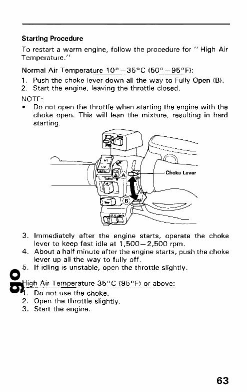
goStarting Procedure
To restart a warm engine, follow the procedure for II High AirTemperature. "
Normal Air Temperature 10° -35°C (50° -95°F):
1. Push the choke lever down all the way to Fully Open (B).2. Start the engine, leaving the throttle closed.
NOTE:• Do not open the throttle when starting the engine with the
choke open. This will lean the mixture, resulting in hardstarting.
3. Immediately after the engine starts, operate the chokelever to keep fast idle at 1,500-2,500 rpm.
4. About a half minute after the engine starts, push the chokelever up all the way to fully off.
5. If idling is unstable, open the throttle slightly.
High Air Temperature 35°C (95°F) or above:
1. Do not use the choke.2. Open the throttle slightly.3. Start the engine.
63

goOPERATION
Low Air Temperature 10°C (50°F) or below:
1. Follow steps 1 - 2 under "Normal Air Temperature."2. When engine rpm begins to pick up, operate the choke lever
to keep fast idle at 2,200- 2,800 rpm.3. To speed warm up, open and close the throttle, keeping
engine rpm below 2,800.4. About 5 minutes after the engine starts, push the choke
lever up all the way to Fully Closed (A).5. Continue warming up the engine by opening and closing the
throttle until it will idle smoothly.
CAUTION:
• Snapping the throttle or fast idling for more than about 5minutes at normal air temperature may cause exhaust pipediscoloration.
• Extended use of the choke may impair piston and cylinderwall lubrication.
Flooded Engine
If the engine fails to start after repeated attempts, it may beflooded with excess fuel. To clear a flooded engine, turn theengine stop switch OFF and push the choke lever up to FullyClosed (A). Open the throttle fully and crank the engine for 5seconds. Wait 10 seconds, then turn the engine stop switchON and follow the "High Air Temperature" Starting Procedure(page 63).
64
goRUNNING-IN
During initial running-in, newly machined surfaces will be incontact with each other and these surfaces will wear in quickly. Running-in maintenance at 1,000 km (600 miles) is designed to compensate for this initial minor wear. Timely performance of running-in maintenance will ensure optimum servicelife and performance from the engine.
The general rules areas follows:
1. Never labour the engine with full throttle at low enginespeeds. This rule is applicable not only during running-inbut at all times.
2. Maximum continuous engine speed during the first 1,000km (600 miles) must not exceed 4,000 min- 1 (rpm)
3. Increase the maximum continuous engine speed by 1,000min- 1 (rpm) between odometer readings of 1,000 km (600miles) and 1,600 km (1,000 miles). Drive briskly, varyspeeds frequently and use full throttle for short bursts only.Do not exceed 5,500 min-1 (rpm).
4. Upon reaching an odometer reading of 1,600 km (1,000miles), you can subject the motorcycle to full throttleoperation. However, do not exceed 5,500 -rnin-1 (rpm) atany time (tachometer RED ZONE limit).
CAUTION:• The red zone indicates the maximum limits of engine speed
and running the engine in the red zone will adversely affectits service life.
65

goOPERATION
RIDING
IImIII• Review Motorcycle Safety (pages 1-8) before you ride.
NOTE:• Make sure the function of the side stand mechanism (See
MAINTENANCE SCHEDULE on page 72, 73 and explanation for SIDE STAND on page 87.)
Proper shifting will provide better fuel economy.
DIIII• Do not downshift when traveling at a speed that would
force the engine to overrev in the next lower gear; the rearwheel may lose traction, resulting in a possible loss of vehicle control.
CAUTION:• Do not shift gears without disengaging the clutch and clos
ing the throttle. The engine and drive train could be damaged by overspeed and shock.
• Do not tow the motorcycle or coast for long distanceswhile the engine is off. The transmission will not be properly lubricated and damage may result.
• Do not exceed 4,500 min- 1 (rpm) when running the enginewithout a load. Serious engine damage may result.
NOTE:• Be careful when revving the engine or accelerating in 1st or
2nd gear as the engine speed will easily enter the red zone.
66

goREVERSE RIDING
For reverse maneuvering, make sure there are no obstacles orpeople in the area; avoid steep or uneven surfaces.
I11III• Do not carry a passenger while moving in reverse. The
weight of a passenger will increase the possibility andresults of maneuvering errors. You may fall over.
1. Make sure the transmission is in neutral (neutral indicatorON) and the side stand is up.
2. Sitting astride the motorcycle, start the engine and shift thereverse lever into the reverse position as shown, then makesure the reverse system indicator comes on.
Reverse
67
goOPERATION
3. Push the start/reverse button and guide the motorcyclebackward cautiously.
CAUTION:• Do not push the start/reverse button more than a minute to
prevent battery discharge.
4. Release the start/reverse button, and the motorcycle willstop.
5. After stopping the motorcycle, disengage the reverse lever,and make sure the reverse gear indicator goes off and theneutral indicator comes on.
CAUTION:• Do not engage or disengage reverse when the motorcycle is
moving or the reverse gears could be damaged.
NOTE:• If the reverse lever is moved to the reverse position with the
engine off, the engine cannot be started.
Reverse System Overload:
The reverse system is designed to move the motorcycle at aconstant slow speed. If the motorcycle begins moving sloweror faster than this speed, due to obstacles or steep pavementangle, the system will shut off (reverse system indicator OFF).To resume reverse operation or normal forward operation,move the reverse lever to the disengaged position and carefully roll the motorcycle to a more-level unobstructed surface,then start again.
68
goBRAKING
This motorcycle is equipped with a unified braking system.Depressing the brake pedal applies the rear brake and the leftfront disc. Operating the brake lever applies the right front disc.For full braking effectiveness, use both the pedal and leversimultaneously, as you would with a conventional motorcyclebrake system.For normal braking, apply both the brake pedal and lever whiledown-shifting to match your road speed. For maximum braking, close the throttle and firmly apply the pedal and lever;disengage the clutch before the motorcycle stops.
l.-• Independent use of only the brake lever or brake pedal
reduces stopping performance.Extreme braking may cause either wheel to lock, reducingcontrol of the motorcycle.
• When possible, reduce speed or brake before entering aturn; closing the throttle or braking in mid-turn may causewheel slip. Wheel slip will reduce control of the motorcycle.
• When riding in wet or rainy conditions, or on loose surfaces,the ability to maneuver and stop will be redu~d.Allof youractions should be smooth under these conditions. Suddenacceleration, braking or turning may cause loss of control.For your safety, exercise extreme caution when braking,accelerating or turning.
• When descending a long, steep grade, use engine compression braking by downshifting, with intermittent use ofbothbrakes. Continuous brake application can overheat thebrakes and reduce their effectiveness.
• Riding with your foot resting on the brake pedal or yourhand on the brake lever may actuate the brakelight, giving afalse indication to other drivers. It may also overheat thebrakes, reducing effectiveness.
69
goOPERATION
PARKING
1. After stopping the motorcycle, shift the transmission intoneutral, turn the ignition switch OFF and remove the key.
2. Use the side or center stand to support the motorcyclewhile parked.
CAUTION:• Park the motorcycle on firm, level ground to prevent it from
falling over.• If you park on a slight incline, aim the front of the motorcy
cle uphill to reduce the possibility of rolling off the sidestand or overturning.
3. Lock the steering to help prevent theft (page 41).
NOTE:• When stopping for a short time near traffic at night, the ig
nition switch may be turned to P and the key removed. Thiswill turn on the taillight to make the motorcycle more visibleto traffic. The battery will discharge if the ignition switch isleft at P for too long a time.
ANTI-THEFT TIPS
1. Always lock the steering and never leave the key in the ignition switch. This sounds simple but people do forget.
2. Be sure the registration information for your motorcycle isaccurate and current.
3. Park your motorcycle in a locked garage whenever possible.4. Use an additional anti-theft device of good quality.5. Put your name, address, and phone number in this Owner's
Manual and keep it on your motorcycle at all times. Manytimes stolen motorcycles are identified by information inthe Owner's Manuals that are still with them.
NAME: ~
ADDRESS: _
PHONE NO: _
70
goMAINTENANCE
• When service is required, remember that your authorizedHonda dealer knows your motorcycle best and is fullyequipped to maintain and repair it. The scheduledmaintenance and the anticipated maintenance may also beperformed by a qualified service facility that normally doesthis kind of work; or you may perform most of the workyourself if you are mechanically qualified and have the proper tools and service data.
• These instructions are based on the assumption that themotorcycle will be used exclusively for its designed purpose. Sustained high speed operation, or operation inunusually wet or dusty conditions, will require more frequent service than specified in the MAINTENANCESCHEDULE. Consult your authorized Honda dealer forrecommendations applicable to your individual needs anduse.
71

goMAINTENANCE
MAINTENANCE SCHEDULE
The following items require some mechanical knowledge. Certain items (particularly those marked * and * *) may requiremore technical information and tools. Consult your authorizedHonda dealer.Perform the Pre-ride Inspection (page 61) at each scheduledmaintenance period.I : INSPECT AND CLEAN, ADJUST, LUBRICATE OR
REPLACE IF NECESSARYC: CLEAN R: REPLACE A: ADJUST L: LUBRICATE
WHICHEVER .. ODOMETER READING (NOTE 11
~COMESFIRST xl.OOO km 1 6 12 18 24 30 36
• xl.ODO mi 0,6 4 8 12 16 20 24 Refer to page
ITEMNOTE MONTHS 6 12 18 24 30 36
FUEL LINE I I I --
THROTTLE OPERATION I I I --
CARBURETOR CHOKE I I I --
AIR CLEANER NOTE 2 R R 77-78
CRANKCASE BREATHER NOTE 3 C C C C C C 78
SPARK PLUGS R R R 83-84
ENGINE OIL R R R R 29. 79- 82
ENGINE OIL FILTER R R R R 80-82
CARBURETOR I I I --SYNCHRONIZATION
CAR8URETOR IDLE SPEED I I I I I I I 86
RADIATOR COOLANT NOTE 4 I I R 24-25
COOLING SYSTEM I I I --
SECONDARY AIR SUPPLY SYSTEM NOTES I I I --
72
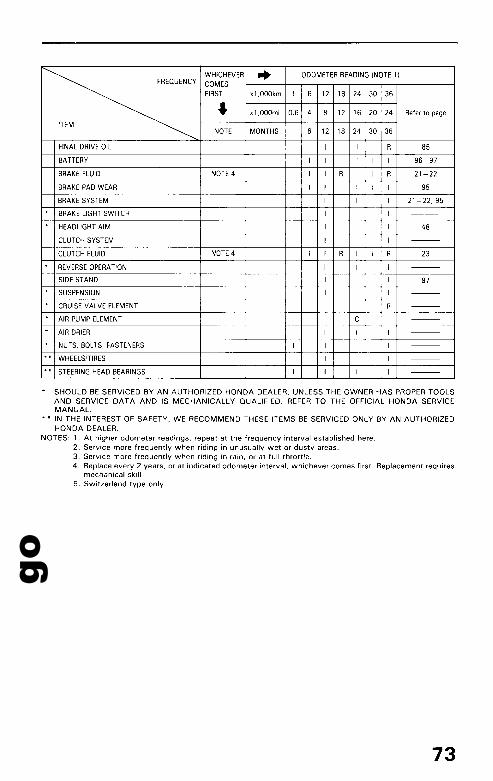
goWHICHEVER ... ODOMETER READING (NOTE 1)
~COMESFIRST x1,000km 1 6 12 18 24 30 36.- x1,000mi 0.6 4 8 12 16 20 24 Refer to page
ITEMNOTE MONTHS 6 12 18 24 30 36
FINAL DRIVE OIL I I R 85
BATTERY I I I I I I 96-97
BRAKE FLUID NOTE 4 I I R I I R 21-22
BRAKE PAD WEAR I I I I I I 95
BRAKE SYSTEM I I I I 21-22,95
BRAKE LIGHT SWITCH I I I ---
HEADLIGHT AIM I I I 48
CLUTCH SYSTEM I I I ---
CLUTCH FLUID NOTE 4 I I R I I R 23
REVERSE OPERATION I I I ---
SIDE STAND I I I 87
SUSPENSION I I I ---
CRUISE VALVE ELEMENT R ---
AIR PUMP ELEMENT C ---
AIR DRIER I I I ---
NUTS, BOLTS, FASTENERS I I I I ---
** WHEELS/TIRES I I I ---
** STEERING HEAD BEARINGS I I I I ---
* SHOULD BE SERVICED BY AN AUTHORIZED HONDA DEALER, UNLESS THE OWNER HAS PROPER TOOLSAND SERVICE DATA AND IS MECHANICALLY QUALIFIED. REFER TO THE OFFICIAL HONDA SERVICEMANUAL.
*. IN THE INTEREST OF SAFETY, WE RECOMMEND THESE ITEMS BE SERVICED ONLY BY AN AUTHORIZEDHONDA DEALER.
NOTES: 1. At higher odometer readings, repeat at the frequency interval established here.2. Service more frequently when riding in unusually wet or dusty areas.3. Service more frequently when riding in rain, or at full throttle.4. Replace every 2 years, or at indicated odometer interval, whichever comes first. Replacement requires
mechanical skill.5. Switzerland type only.
73
go
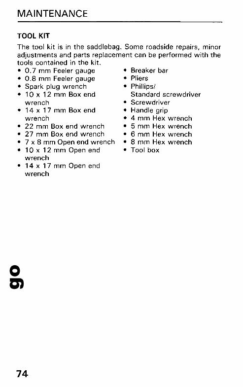
• Breaker bar• Pliers• Phillips/
Standard screwdriver• Screwdriver• Handle grip• 4 mm Hex wrench• 5 mm Hex wrench• 6 mm Hex wrench• 8 mm Hex wrench• Tool box
MAINTENANCE
TOOL KIT
The tool kit is in the saddlebag. Some roadside repairs, minoradjustments and parts replacement can be performed with thetools contained in the kit.• 0.7 mm Feeler gauge• 0.8 mm Feeler gauge• Spark plug wrench• 10 x 12 mm Box end
wrench• 14 x 17 mm Box end
wrench• 22 mm Box end wrench• 27 mm Box end wrench• 7 x 8 mm Open end wrench• 10 x 12 mm Open end
wrench• 14 x 17 mm Open end
wrench
74
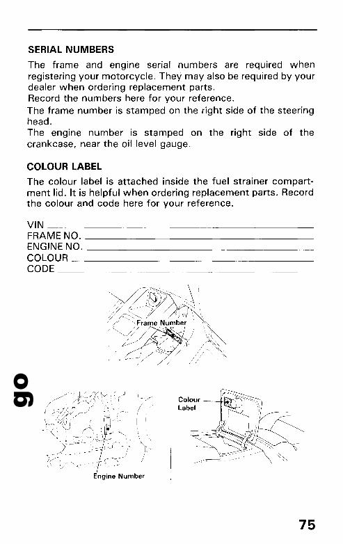
goSERIAL NUMBERS
The frame and engine serial numbers are required whenregistering your motorcycle. They may also be required by yourdealer when ordering replacement parts.Record the numbers here for your reference.The frame number is stamped on the right side of the steeringhead.The engine number is stamped on the right side of thecrankcase, near the oil level gauge.
COLOUR LABEL
The colour label is attached inside the fuel strainer compartment lid. It is helpful when ordering replacement parts. Recordthe colour and code here for your reference.
VIN _FRAME NO. _ENGINE NO. _COLOUR _CODE _
Colour ---+Hi,*"
Label
75
goMAINTENANCE
MAINTENANCE PRECAUTIONS
!BIB• If your motorcycle is overturned or involved in a collision,
inspect control levers, cables, brake hoses, calipers, accessories, and other vital parts for damage. Do not ride themotorcycle if damage impairs safe operation. Have yourauthorized Honda dealer inspect the major components, including frame, suspension and steering parts, for misalignment and damage that you may not be able to detect.
• Stop the engine and support the motorcycle securely on afirm, level surface before performing any maintenance.
• Use new, genuine Honda parts or their equivalent formaintenance and repair. Parts which are not of equivalentquality may impair the safety of your motorcycle.
76
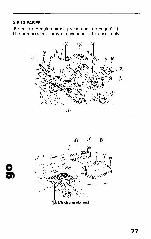
goAIR CLEANER
(Refer to the maintenance precautions on page 61.)The numbers are shown in sequence of disassembly.
77

goMAINTENANCE
The air cleaner should be serviced at regular intervals (page73). Service more frequently when riding in unusually wet ordusty areas.1. Remove the seat (page 49).2. Remove the parts in sequence, according to the order in
the illustration.
NOTE:• Be careful not to break any tabs.
3. Remove and discard the air cleaner element.4. Install a new air cleaner element.5. Install removed parts in the reverse order of removal.
NOTE:• Make sure to engage all tabs and to secure all fasteners.
CRANKCASE BREATHER
(Refer to the maintenance precaution on page 61.)1. Remove the front left side cover.2. Remove the drain plug from the tube and drain deposits.3. Reinstall the drain plug.
NOTE:• Service '!lore frequently when ridden in rain, at full throttle,
or after the motorcycle is washed or overturned. Service ifthe deposit level can be seen in the transparent section ofthe drain tube.
Crankcase Breather Tube
78
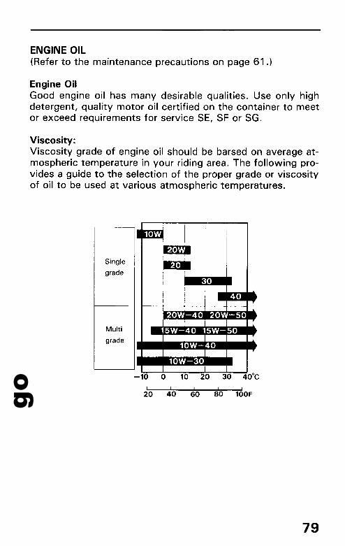
goENGINE OIL(Refer to the maintenance precautions on page 61.)
Engine OilGood engine oil has many desirable qualities. Use only highdetergent, quality motor oil certified on the container to meetor exceed requirements for service SE, SF or SG.
Viscosity:Viscosity grade of engine oil should be barsed on average atmospheric temperature in your riding area. The following provides a guide to the selection of the proper grade or viscosityof oil to be used at various atmospheric temperatures.
Single
grade
Multi
grade
79
go
j i/~ L
MAINTENANCE
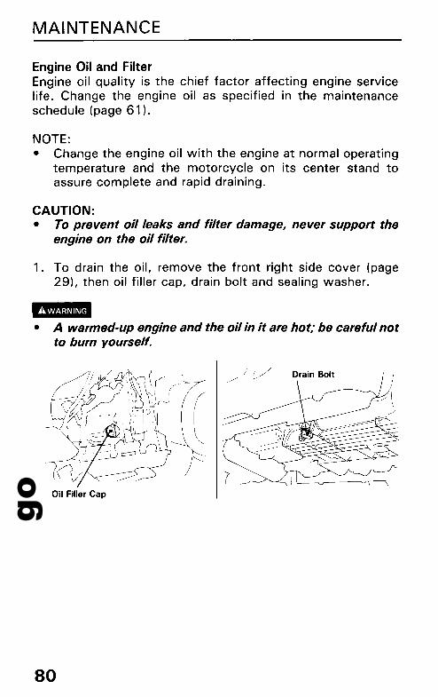
Engine Oil and FilterEngine oil quality is the chief factor affecting engine servicelife. Change the engine oil as specified in the maintenanceschedule (page 61 ).
NOTE:• Change the engine oil with the engine at normal operating
temperature and the motorcycle on its center stand toassure complete and rapid draining.
CAUTION:• To prevent oil leaks and filter damage, never support the
engine on the oil filter.
1. To drain the oil, remove the front right side cover (page29), then oil filler cap, drain bolt and sealing washer ..,.
• A warmed-up engine and the oil in it are hot; be careful notto burn yourself.
Oil Filler Cap
80

go2. Remove the under cover and oil filter with a filter wrench.
Discard the oil filter.
OilFilter
Under Cover
3. Apply a thin coat of engine oil to the new oil filter rubberseal.
Rubber --¥c~~Seal
Oil Filter
4. Install the new oil filter and tighten it: 10 N·m (1.0 kg-m,7 ft-Ib)
81

goMAINTENANCE
5. Check that the sealing washer on the drain plug is in goodcondition and Install the drain plug.Oil Drain Plug Torque:40 N·m (4.0 kg-m, 29 ft-lb)
6. Fill the crankcase with the recommended grade oil;approximately:3.7 £ (3.8 US qt, 3.3 Imp qt)
7. Install the oil filler cap.8. Start the engine and let it idle for 2-3 minutes.9. Stop the engine. Check that the oil level is at the upper
level mark on the dipstick (page 29). Make sure there areno oil leaks.
NOTE:• When running in very dusty conditions, oil changes should
be performed more frequently than specified in themaintenance schedule.
• Please dispose of used engine oil in a manner that is compatible with the environment. We suggest you take it in asealed container to your local service station for reclamation. Do not throw it in the rubbish or pour it on the ground.
CAUTION:• Used engine oil may cause skin cancer if repeatedly left in
contact with the skin for prolonged periods. Although thisis unlikely unless you handle used oil on a daily basis, it isstill advisable to thoroughly wash your hands with soapand water as soon as possible after handling used oil.
82
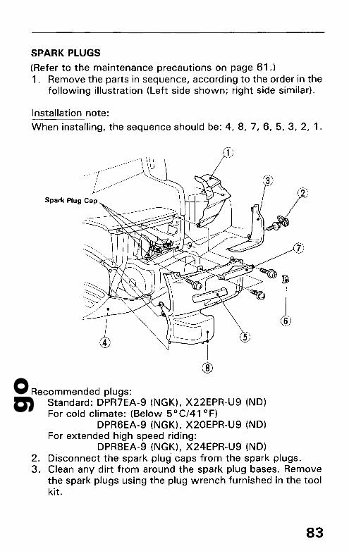
goSPARK PLUGS
(Refer to the maintenance precautions on page 61.)1. Remove the parts in sequence, according to the order in the
following illustration (Left side shown; right side similar).
Installation note:
When installing, the sequence should be: 4, 8, 7, 6, 5, 3, 2, 1.
Spark Plug Cap
>~l-~
6
Recommended plugs:Standard: DPR7EA-9 (NGK), X22EPR-U9 (ND)For cold climate: (Below 50 Cf41 0F)
DPR6EA-9 (NGK), X20EPR-U9 (ND)For extended high speed riding:
DPR8EA-9 (NGK), X24EPR-U9 (ND)2. Disconnect the spark plug" caps from the spark plugs.3. Clean any dirt from around the spark plug bases. Remove
the spark plugs using the plug wrench furnished in the toolkit.
83

goMAINTENANCE
4. Inspect the electrodes and center porcelain for deposits,erosion or cabon fouling. If the erosion or deposit is heavy,replace the plug. Clean a carbon or wet-fouled plug with aplug cleaner, otherwise use a wire brush.
5. Check the spark plug gap using a wiretype feeler gauge. Ifadjustment is necessary, bend the side electrode carefully.The gap should be:
0.8-0.9 mm (0.031-0.035 in)Make sure the plug washer is in good condition.
6. With the plug washer attached, thread the spark plug in byhand to prevent crossthreading.
7. Tighten a new spark plug 1/2 turn with a spark plugwrench to compress the washer. If you are reusing a plug,it should only take 1/8 - 1/4 turn after the plug seats.
8. Reinstall the spark plug caps.
CAUTION:• The spark plug must be securely tightened. An improperly
tightened plug can become very hot and possibly damagethe engine.
• Never use a spark plug with an improper heat range.Severe engine damage culd result.
84
~0.8-0.9 mm(0.031-0.035 in) i
Side Electrode
, Washer
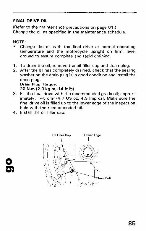
goFINAL DRIVE OIL
(Refer to the maintenance precautions on page 61.)Change the oil as specified in the maintenance schedule.
NOTE:• Change the oil with the final drive at normal operating
temperature and the motorcycle upright on firm, levelground to assure complete and rapid draining.
1. To drain the oil, remove the oil filler cap and drain plug.2. After the oil has completely drained, check that the sealing
washer on the drain plug is in good condition and install thedrain plug.Drain Plug Torque:20 N·m (2.0 kg-m, 14 ft-Ib)
3. Fill the final drive with the recommended grade oil; approximately: 140 cm 3 (4.7 US OZ, 4.9 Imp oz). Make sure thefinal drive oil is filled up to the lower edge of the inspectionhole with the recommended oil.
4. Install the oil filler cap.
Oil Filler Cap
85

goMAINTENANCE
IDLE SPEED
(Refer to the maintenance precautions on page 61.)The idle speed adjustment procedure given here should only beused when changes in altitude affect normal idle speed as setby your dealer. See your authorized Honda dealer for regularlyscheduled carburetor adjustments, including individual carburetor adjustment and synchronization.
NOTE:• The engine must be at normal operating temperature for ac
curate idle speed adjustment. Ten minutes of stop-and-goriding is sufficient.
1. Warm up the engine, shift to neutral and place the motorcycle on its center stand.
2. Open the fuel strainer compartment.3. Adjust idle speed with the adjusting knob.
Idle Speed (In neutral):800±80rpm
Adjusting Knob
Fuel StrainerCompartment
86
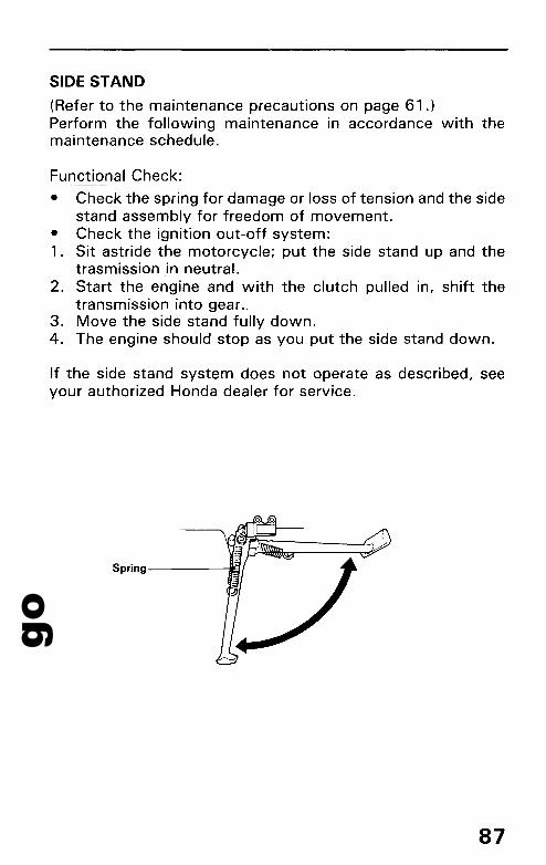
goSIDE STAND
(Refer to the maintenance precautions on page 61 .)Perform the following maintenance in accordance with themaintenance schedule.
Functional Check:
• Check the spring for damage or loss of tension and the sidestand assembly for freedom of movement.
• Check the ignition out-off system:1. Sit astride the motorcycle; put the side stand up and the
trasmission in neutral.2. Start the engine and with the clutch pulled in, shift the
transmission into gear.3. Move the side stand fully down.4. The engine should stop as you put the side stand down.
If the side stand system does not operate as described, seeyour authorized Honda dealer for service.
Spring------tI9/
87
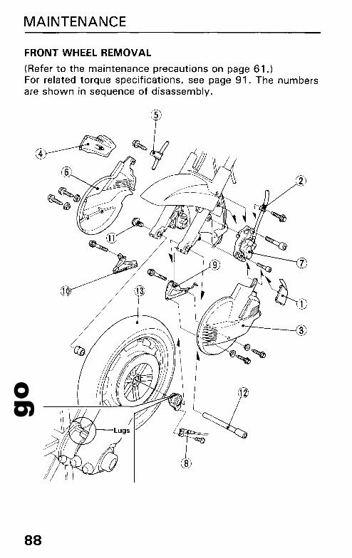
goMAINTENANCE
FRONT WHEEL REMOVAL
(Refer to the maintenance precautions on page 61.)For related torque specifications, see page 91. The numbersare shown in sequence of disassembly.
88
go--• Wheel removal requires mechanical skill and professional
tools such as a floor jack and torque wrench. We recommend it be done only by your authorized Honda dealer orother qualified mechanic.
1. Raise the front wheel off the ground by placing a supportblock under the engine.
2. Remove the parts in sequence, according to the order in theillustration.
CAUTION:• To avoid damage to the brake hose, support the caliper
assembly so that it doesn't hang from the hose. Do nottwist the brake hose.
• A void getting grease, oil or dirt on the disc or pad surfaces,because such contamination can cause poor brake performance or rapid pad wear after reassembly.
NOTE:• Do not depress the brake lever and brake pedal when the
wheel is off the motorcycle. The caliper pistons will beforced out of the cylinders with subsequent loss of brakefluid. If this occurs, servicing of the brake system will benecessary. See your authorized Honda dealer for thisservice.
89

goMAINTENANCE
Installation
1. Reassemble removed parts in the reverse order of removal.
NOTE:• When installing the wheel, position the speedometer gear
box so that the lug on the gearbox is against the rear of thestopper lug on the left fork.
CAUTION:• When installing the wheel, fit both brake discs carefully be
tween the brake pads to avoid damaging the pads.
2. Measure the clearance between the out side surface of theleft brake disc and the left caliper holder with a 0.7 mm(0.028 in) feeler gauge. If the gauge inserts easily, tightenthe right and left axle pinch bolts to the specified torque.
90
goSpecified torque:
Axle bolt: 90 Nom (9.0 kg-m, 65 ft-Ib)Caliper mounting bolt, upper: 23 Nom (2.3 kg-m, 16 ft-Ib)Caliper mounting bolt, lower: 12 Nom (1.2 kg-m, 9 ft-Ib)Axle pinch bolt: 22 Nom (2.2 kg-m, 16 ft-Ib)
!BIll• If a torque wrench was not used for installation, see your
authorized Honda dealer as soon as possible to verify proper assembly. Improper assembly may lead to loss ofbraking capability.
3. If the feeler gauge cannot be inserted easily, pull the leftfork outward or push inward until the gauge can be inserted and tighten the axle pinch bolts with the gaugeinserted.
4. After tightening, remove the gauge. After installing thewheel, apply the brakes several times, then recheck bothdiscs for caliper holder to disc clearance. Do not operatethe motorcycle without adequate clearance.
!BIll• Failure to provide adequate disc to caliper holder clearance
may damage the brake discs and impair braking efficiency.
91

goMAINTENANCE
REAR WHEEL REMOVAL
® (Disconnect thelead connector of--"-~T--each side.)
Q~ (Loosen bolts of each side) ~j; (Each side)
92
go-• Wheel removal requires mechanical skill and professional
tools such as a torque wrench. We recommend it be doneonly by your authorized Honda dealer or other qualifiedmechanic.
1. Place the motorcycle on its center stand.2. Remove the parts in sequence, according to the order in
the illustration.
CAUTION:• Support the caliper assembly before removing the rear axle
so that the caliper does not hang from the brake hose. Donot twist the brake hose.
• A void getting grease, oil or dirt on the disc orpad surfaces,because such contamination can cause poor brake performance or rapid pad wear after reassembly.
• Do not damage the muffler gaskets when handling themufflers.
NOTE:• Do not depress the brake pedal while the wheel is off the
motorcycle. The caliper pistons will be forced out of thecylinder with subsequent loss of brake fluid. If this occurs,servicing of the brake system will be neceS6ary. See yourauthorized Honda dealer for this service.
Installation
1. Reassemble removed parts in the reverse order of removal.
CAUTION:• Do not pinch, or twist the air hose when installing the right
saddlebag.
NOTE:• Apply a lithium-based multipurpose grease with molyb
denum disulfide additive to the rear hub splines, final drivegear splines and flange pins when the rear wheel isreassembled. Be sure the splines on the wheel hub fit intothe final drive case and the splines on the final drive case fitinto the driveshaft end.
93
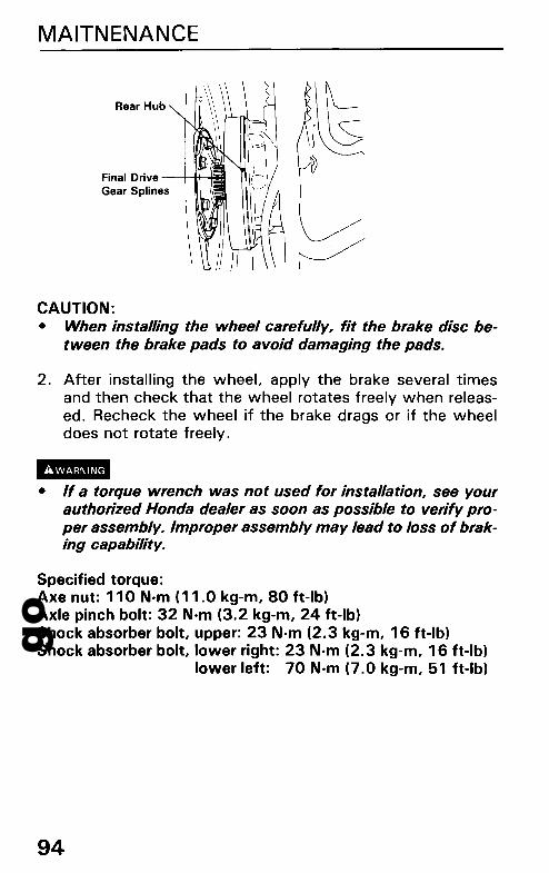
goMAITNENANCE
Rear Hub
Final Drive-~HGear Splines
CAUTION:• When installing the wheel carefully, fit the brake disc be
tween the brake pads to avoid damaging the pads.
2. After installing the wheel, apply the brake several timesand then check that the wheel rotates freely when released. Recheck the wheel if the brake drags or if the wheeldoes not rotate freely.
-• If a torque wrench was not used for installation, see yourauthorized Honda dealer as soon as possible to verify proper assembly. Improper assembly may lead to loss of braking .capability.
Specified torque:Axe nut: 110 Nom (11.0 kg-m, 80 ft-Ib)Axle pinch bolt: 32 Nom (3.2 kg-m, 24 ft-Ib)Shock absorber bolt, upper: 23 Nom (2.3 kg-m, 16 ft-Ib)Shock absorber bolt, lower right: 23 N·m (2.3 kg-m, 16 ft-Ib)
lower left: 70 Nom (7.0 kg-m, 51 ft-Ib)
94

goBRAKE PAD WEAR
(Refer to the maintenance precautions on page 61.)Brake pad wear will depend upon the severity of usage, type ofriding and condition of the roads. The pads will wear faster ondirty and wet roads. Inspect the pads visually during all regularservice intervals to determine the pad wear. If either pad wearsto the wear limit, both pads must be replaced as a set.
NOTE:• Use only genuine Honda replacement friction pads offered
by authorized Honda dealers.When brake service is necessary consult your Hondadealer.
Other Checks:
Make sure that there are no fluid leaks. Check for deteriorationor cracks in the hoses and fittings.
FRONT
95
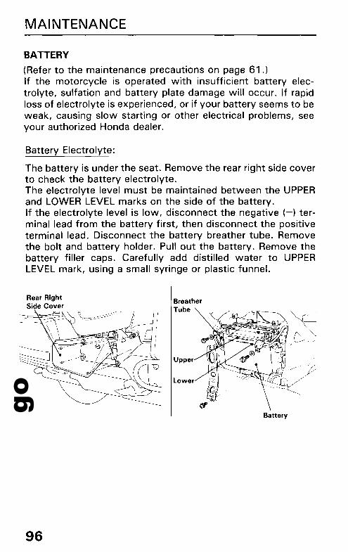
goMAINTENANCE
BATTERY
(Refer to the maintenance precautions on page 61.)If the motorcycle is operated with insufficient battery electrolyte, sulfation and battery plate damage will occur. If rapidloss of electrolyte is experienced, or if your battery seems to beweak, causing slow starting or other electrical problems, seeyour authorized Honda dealer.
Battery Electrolyte:
The battery is under the seat. Remove the rear right side coverto check the battery electrolyte.The electrolyte level must be maintained between the UPPERand LOWER LEVEL marks on the side of the battery.If the electrolyte level is low, disconnect the negative (-) terminal lead from the battery first, then disconnect the positiveterminal lead. Disconnect the battery breather tube. Removethe bolt and battery holder. Pull out the battery. Remove thebattery filler caps. Carefully add distilled water to UPPERLEVEL mark, using a small syringe or plastic funnel.
Rear RightSide Cover
96
BreatherTube
Upper
lower
Battery
goCAUTION:• When checking the battery electrolyte level, or adding
distilled water, make sure the breather tube is connected tothe battery breather outlet.
• Use only distilled water in the battery. Tap water willshorten the service life of the battery.
• Filling the battery above the UPPER LEVEL line may causethe electrolyte to overflow, resulting in corrosion to engineor nearby parts. Immediately wash off any spilledelectrolyte.
• The battery breather tube must be routed as shown on thelabel. Do not bend or twist the breather tube. A bent orkinked breather tube may pressurize the battery anddamage its case.
Il!I!III• The battery gives offexplosive gases; keep sparks, flames,
and cigarettes away. Provide adequate ventilation whencharging or using the batteries in an enclosed space.
• The battery contains sulfuric acid (electrolyte). Contactwith skin or eyes may cause severe burns. Wear protectiveclothing and a face shield.-If electrolyte gets on your skin, flush with water.-If electrolyte gets in your eyes, flush with water for at
least 15 minutes and call a physician immediately.• Electrolyte is poisonous.
-If swallowed, drink large quantities of water or milk andfollow with milk of magnesia or vegetable oil and call aphysician.
• KEEP OUT OF REACH OF CHILDREN.
97
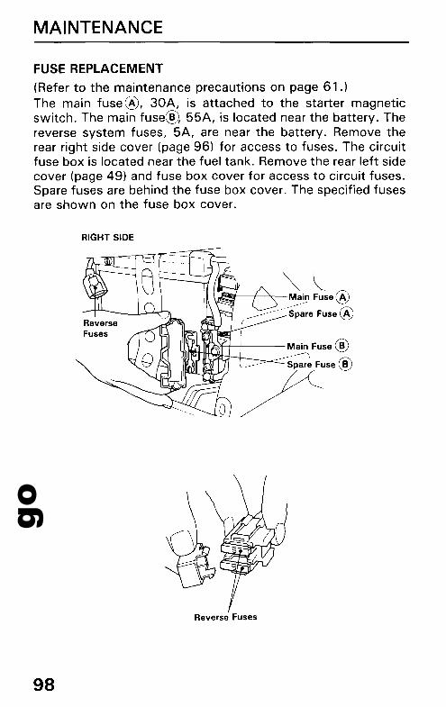
goMAINTENANCE
FUSE REPLACEMENT
(Refer to the maintenance precautions on page 61 .)The main fuse@, 30A, is attached to the starter magneticswitch. The main fuse@, 55A, is located near the battery. Thereverse system fuses, 5A, are near the battery. Remove therear right side cover (page 96) for access to fuses. The circuitfuse box is located near the fuel tank. Remove the rear left sidecover (page 49) and fuse box cover for access to circuit fuses.Spare fuses are behind the fuse box cover. The specified fusesare shown on the fuse box cover.
RIGHT SIDE
~~JiiiiI;'i----+-~-Main Fuse @
_____~--~- S;~~e Fuse @(
",,,...,,~If":-,~-+-I----- Main Fuse@
'- Spar~ Fuse ®
~
Reverse Fuses
98
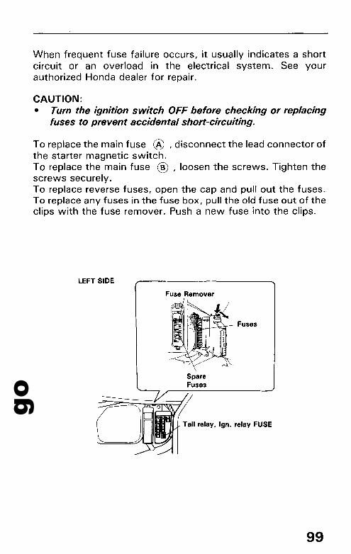
goWhen frequent fuse failure occurs, it usually indicates a shortcircuit or an overload in the electrical system. See yourauthorized Honda dealer for repair.
CAUTION:• Turn the ignition switch OFF before checking or replacing
fuses to prevent accidental short-circuiting.
To replace the main fuse ® ,disconnect the lead connector ofthe starter magnetic switch.To replace the main fuse ® ' loosen the screws. Tighten thescrews securely.To replace reverse fuses, open the cap and pull out the fuses.To replace any fuses in the fuse box, pull the old fuse out of theclips with the fuse remover. Push a new fuse into the clips.
LEFT SIDE
Fuse Remover
Fuses
SpareFuses
Tail relay, Ign. relay FUSE
99

goMAINTENANCE
amIII• Never use a fuse with a different rating from that specified.
Serious damage to the electrical system or a fire may result,causing a dangerous loss of lights or engine power.
100
FuseRemover
Blown Fuse
goCLEANING
Clean your motorcycle regularly to protect the surface finishesand inspect for damage, wear, and oil, coolant, or hydraulicfluid seepage.1. Clean the windshield with a soft cloth or sponge and plenty
of water. Dry with a soft clean cloth. Remove minor scratches with commercially available plastic polishing compound. Replace the windshield if scratches cannot beremoved and they obstruct clear vision.
CAUTION:• Do not let battery electrolyte, brake fluid or other acid
chemicals get on the windshield. They will damage theplastic.
• A void spraying high pressure water (typical in coin-operated car washes) at the following areas:
Brake Master Cylinders Fairing Pockets or AccessoriesClutch Master Cylinder Ignition SwitchRadiator Fins Steering LockWheel Hubs Handlebar SwitchesMuffler Outlets Instrument panelUnder Seat Radio Unit
2. After cleaning, rinse the motorcycle thoroughly with plentyof clean water. Strong detergent residue can corrode alloyparts.
3. Dry the motorcycle, start the engine, and let it run forseveral minutes.
4. Test the brakes before riding the motorcycle. Several applications may be necessary to restore normal brakingperformance.
1mB• Braking efficiency may be temporarily impaired immediately
after washing the motorcycle. Anticipate longer stoppingdistance to avoid a possible accident.
101

goCLEANING
Aluminum Wheel Maintenance
Aluminum corrodes when it comes in contact with dust, mud,road salt, etc. After riding, clean the wheels with a wet spongeand mild detergent, then rinse well with water and wipe drywith a clean cloth. After cleaning, apply wax to the cleanedsurfaces thoroughly.If the wheels have stains or lose their luster, polish the surfaces with a cleaner containing compounds, then apply wax.Be sure to remove wax or cleaner from the brake discthoroughly after applying wax or polishing with a cleaner containing compounds.
CAUTION:• Do not use steel wool to clean the wheels, as they can
cause damage.
102
goSTORAGE GUIDE
STORAGE
Extended storage, such as for winter, requires that you takecertain steps to reduce the effects of deterioration from nonuse of the motorcycle. In addition, necessary repairs should bemade BEFORE storing the motorcycle; otherwise, these repairsmay be forgotten by the time the motorcycle is removed fromstorage.
1. Change the engine oil and filter.2. Make sure the cooling system is filled with a 50/50% an
tifreeze solution.3. Drain the fuel tank and carburetors into an approved
gasoline container. Spray the inside of the tank with anaerosol rust-inhibiting oil.Reinstall the fuel cap on the tank.
NOTE:• If storage will last more than one month, carburetor drain
ing is very important, to assure proper performance afterstorage.
-• Petrol is extremely flammable and is explosive under cer-tain conditions. Perform this operation in a well-ventilatedarea with the engine stopped. Do not smoke or allowflames or sparks near the equipment while draining fuel.
4. Remove the spark plugs and pour a tablespoon (1 5 - 20cm 3 ) of clean engine oil into each cylinder. Crank theengine several times to distribute the oil, then reinstall thespark plugs.
NOTE:• When turning the engine over, the Engine Stop Switch
should be OFF and each spark plug placed in its cable capand grounded to prevent damage to the ignition system.
5. Remove the battery. Store in an area protected from freezing temperatures and direct sunlight. Check the electrolytelevel and slow charge the battery once a month.
103

goSTORAGE GUIDE
6. Wash and dry the motorcycle. Wax all painted surfaces.Coat chrome with rust-inhibiting oil.
7. Inflate the tyres to their recommended pressures. Place themotorcycle on blocks to raise both tyres off the ground.
8. Cover the motorcycle (don't use plastic or other coatedmaterials) and store in an unheated area, free of dampnesswith a minimum of daily temperature variation. Do not storethe motorcycle in direct sunlight.
REMOVAL FROM STORAGE
1. Uncover and clean the motorcycle. Change the engine oil ifmore than 4 months have passed since the start of storage.
2. Check the battery electrolyte level and charge the batteryas required. Install the battery.
3. Drain any excess aerosol rust-inhibiting oil from the fueltank. Fill the fuel tank with fresh petrol.
4. Check the final drive oil, adding the recommended gear oil ifnecessary. Change the final drive oil as specified by theMaintenance Schedule. Perform all Pre-ride Inspectionchecks (page 61 ). Test ride the motorcycle at low speeds ina safe riding area away from traffic.
104
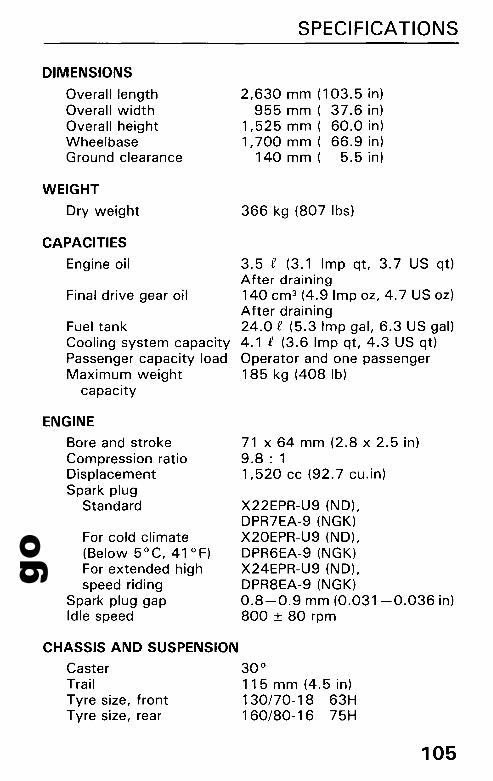
goDIMENSIONS
Overall lengthOverall widthOverall heightWheelbaseGround clearance
WEIGHT
Dry weight
CAPACITIES
Engine oil
Final drive gear oil
Fuel tankCooling system capacityPassenger capacity loadMaximum weight
capacity
ENGINE
Bore and strokeCompression ratioDisplacementSpark plug
Standard
For cold climate(Below 5°C, 41°F)For extended highspeed riding
Spark plug gapIdle speed
SPECIFICATIONS
2,630 mm (103.5 in)955 mm ( 37.6 in)
1,525 mm ( 60.0 in)1,700 mm ( 66.9 in)
140 m m ( 5.5 in)
366 kg (807 Ibs)
3.5 £ (3.1 Imp qt, 3.7 US qt)After draining140 cm 3 (4.9 Imp oz, 4.7 US oz)After draining24.0 £ (5.3 Imp gal, 6.3 US gal)4.1 £ (3.6 Imp qt, 4.3 US qt)Operator and one passenger185 kg (408 Ib)
71 x 64 mm (2.8 x 2.5 in)9.8 : 11,520 cc (92.7 cu.in)
X22EPR-U9 (ND),DPR7EA-9 (NGK)X20EPR-U9 (ND),DPR6EA-9 (NGK)X24EPR-U9 (ND),DPR8EA-9 (NGK)0.8-0.9 mm (0.031-0.036 in)800 ± 80 rpm
CHASSIS AND SUSPENSION
Caster 30°Trail 11 5 mm (4.5 in)Tyre size, front 130/70-18 63HTyre size, rear 160/80-16 75H
105

goSPECIFICATIONS
POWER TRANSMISSION
Primary reductionSecondary reductionGear ratio, 1st
2nd3rd4th00
Final reduction
ELECTRICAL
BatteryGenerator
LIGHTS
HeadlightTail/stoplightTurn signal lightPosition light
License light
FUSES
106
1.5920.9712.6671.7221.2730.9640.7592.833
12V-20AH0.55 kw/5,OOO rpm
12V-60/55W12V-5/21W12V-21W12V 5W
12V 5W
65A, 5A (Reverse fuse)55A, 30A (Main fuse)15A, 10A, 5A (Other fuse)

goNOISE CONTROL SYSTEM (AUSTRALIA ONLY)
TAMPERING WITH NOISE CONTROL SYSTEM PROHIBITED
Owners are warned that the law may prohibit:(a) The removal or rendering inoperative by any person other
than for purposes of maintenance, repair or replacement,of any device or element of design incorporated into anynew vehicle for the purpose of noise control prior to its saleor delivery to the ultimate purchaser or while it is in use;and
(b) The use of the vehicle after such device or element ofdesign has been removed or rendered inoperative by anyperson.
107

go