Embed Size (px)
Citation preview

SM
GPS 95 STDPERSONAL NAVIGATOR TM
OWNER'S MANUAL
KPTS
KOJC
KSGF

GPS 95 STD
Personal Navigator TM
OWNER'S MANUAL

© 1993 GARMIN, 9875 Widmer Road, Lenexa, KS 66215, USA
Printed in Taiwan.
All rights reserved. No part of this manual may be reproduced or transmittedin any form or by any means, electronic or mechanical, including photocopyingand recording, for any purpose without the express written permission ofGARMIN.
Information in this document is subject to change without notice. GARMINreserves the right to change or improve their products and to make changesin the content without obligation to notify any person or organization of suchchanges or improvements.
July, 1993 190-00054-00 Rev. A

i
PREFACE
GARMIN thanks you for selecting our high performance, full featuredPersonal NavigatorTM. The GPS 95 represents our continued commitmentto provide you with a portable navigation unit that is versatile, extremelyaccurate, and easy to use. We are confident you will enjoy using your unitfor many years to come.
The GPS 95's rugged construction and quality components offer the reliabilitydemanded by the harshest operating environments. It may be used inaircraft, marine vessels and land vehicles, as well as by hunters, hikers, andmilitary forces. The unit may be operated portably using its own battery pack,or it may use a 5-40 volt DC external power source for fixed mountedapplications. You can even use a 115- or 230-volt AC adaptor for planningtrips at home.
This manual and accompanying quick reference card provide completeinformation on safely operating the GPS 95 to its full potential. A sample triphas been planned for you to practice your navigation skills using the built-insimulator. Afterwards, try a trip of your own to realize the value of the GPS95 as your Personal NavigatorTM. If you have any questions or comments,our Product Support Department is eager to serve you. GARMIN is fullycommitted to your satisfaction as a customer.
GARMIN International, Inc.9875 Widmer RoadLenexa, KS 662151-800-800-1020(913) 599-1515

ii
CAUTION
The GPS system is operated by the government of the United States whichis solely responsible for its accuracy and maintenance. The system is underdevelopment and is subject to changes which could affect the accuracy andperformance of all GPS equipment. Although the GPS 95 is a precisionelectronic NAVigation AID (NAVAID), any NAVAID can be misused ormisinterpreted, and therefore become unsafe. Use the GPS 95 at your ownrisk. To reduce the risk, carefully review and understand all aspects of thisOwner's Manual and thoroughly practice operation using the simulator modeprior to actual use. When in actual use, carefully compare indications fromthe GPS 95 to all available navigation sources including the information fromother NAVAIDs, visual sightings, charts, etc. For safety, always resolve anydiscrepancies before continuing navigation.
NOTE: This device complies with Part 15 of the FCC Rules. Operation issubject to the following two conditions: (1) This device may not causeharmful interference, and (2) this device must accept any interferencereceived, including interference that may cause undesired operation.

iii
TABLE OF CONTENTS
CHAPTER PAGE
1 INTRODUCING THE GARMIN GPS 95 1-1
1.1 Capabilities 1-11.2 Basic Package 1-21.3 Optional Accessories 1-31.4 Operational Modes 1-4
2 GETTING STARTED 2-1
2.1 Front Panel 2-12.2 Softkey Operation 2-12.3 Cursor and Fields 2-22.4 Keypad Operation 2-22.5 Entering Data 2-42.6 Viewing Messages 2-52.7 Turning the GPS 95 On 2-52.8 Turning the GPS 95 Off 2-72.9 Learning to Use the GPS 95 2-7
3 WAYPOINTS 3-1
3.1 Waypoint Definition Page 3-23.2 Creating Waypoints 3-33.3 Waypoint List 3-53.4 Using Waypoints 3-63.5 Reviewing Waypoints 3-73.6 Proximity Alarm Waypoints 3-83.7 Nearest Waypoints 3-9
4 GETTING THERE FAST - GOTO 4-1
5 NAVIGATION INFORMATION 5-1
5.1 Navigation Summary Page 5-15.2 Map Display 5-3

iv
5.3 Map Configuration 5-55.4 Present Position 5-65.5 Sample Trip 5-7
6 ROUTES 6-1
6.1 Route Definition 6-26.2 Creating and Copying Routes 6-36.3 Activating and Inverting Routes 6-46.4 Editing Routes 6-46.5 Deleting Routes 6-56.6 Active Route 6-56.7 Route List 6-6
7 AUTOSTORETM 7-1
7.1 Creating Waypoints with AutostoreTM 7-17.2 Building Routes with AutostoreTM 7-2
8 GPS STATUS AND AUXILIARY FUNCTIONS 8-1
8.1 Bar Graph Display 8-28.2 Satellite Status Page 8-38.3 Satellite Skyview Page 8-48.4 Auxiliary Menu 8-48.5 Operating Mode/Filters 8-48.6 Track Log Setup 8-58.7 Units/Heading Setup 8-78.8 Alarms/CDI Setup 8-88.9 Date/Time 8-108.10 Audio and Display Setup 8-118.11 Interface Setup 8-128.12 Map Datum Selection 8-148.13 Messages 8-158.14 Density Altitude/True Airspeed/Winds Loft 8-158.15 Sunrise/Sunset Planning 8-168.16 Trip and Fuel Planning 8-178.17 Vertical Navigation Planning 8-18
9 SAMPLE TRIP USING ROUTES 9-1

v
APPENDICES
A MESSAGES A-1
B GLOSSARY AND NAVIGATION TERMS B-1
B.1 Definitions B-1B.2 Course To Steer (CTS) B-3
C INSTALLATION AND MAINTENANCE C-1
C.1 Specifications C-1C.2 Electrical Wiring C-3C.3 Yoke Mount Installation C-4C.4 Yoke Mount Operation C-6C.5 Portable Antenna Installation C-8C.6 Battery Pack Operation C-8C.7 Maintenance C-10C.8 Product Support C-10
D MAP DATUMS D-1
E UTC TIME TO LOCAL TIME OFFSET E-1
F INDEX F-1

1-1
CHAPTER 1INTRODUCING THE GARMIN GPS 95
1.1 CAPABILITIES
The GPS 95 provides a host of powerful capabilities which were previouslyfound only in much larger systems:
· Performance: MultiTracTM receiver tracks and uses up to eightsatellites with high sensitivity, fast first fix, and continuous navigationupdates.
· Portability: Goes anywhere - air, sea or land. Built-in simulator fortrip planning or practicing navigation skills anywhere.
· Ease of Use: Graphic screens and intuitive guidance from the displayoffer ease of operation.
· Navigation: Stores 500 alphanumeric user waypoints; 20 reversibleroutes of 30 waypoints each. GOTO function sets instantaneouscourse to waypoint of your choice. AutoStoreTM function builds routesas you go. A flashing message annunciator keeps you fully informedof your navigation status.
· Personalized: Customize your unit by selecting distance and speedunits, Course Deviation Indicator (CDI) sensitivity, keypad and displayfeatures, map datums, and interface options.
· Low Power Consumption: Battery Saver operation draws less than1.5 watts; provides up to four hours of continuous operation with theAA battery pack.
· Trip Planning: Analyze distance, time, and fuel requirements for yourtrip. Compute time of sunrise/sunset at your destination. Calculatedensity altitude before you take off and true airspeed as you fly.Vertical navigation guides you to your cruising altitude and puts you inthe traffic pattern before landing.
· Alarms: An alarm clock and timer allow the GPS 95 to watch the clockfor you. Arrival and CDI alerts help you safely navigate your aircraft.
· Interfaces: Interface with PC-based moving map programs usingNMEA 0183 output, with Differential GPS (DGPS) receivers usingRTCM (SC-104 version 2.0) input, or with marine autopilots and

1-2
graphic plotters using NMEA 0180/0182/0183 outputs. An optionalPC kit is also available to download user waypoints and routes to yourPC for permanent record.
We encourage you to read this manual and experiment using the built-insimulator. This will help you quickly master the many features of the GPS 95.
1.2 BASIC PACKAGE
Your GARMIN GPS 95 basic package includes:
· GPS 95 Unit· AA Battery Pack· Detachable Antenna· Remote Antenna Cable w/Suction Cup Mount· Yoke Mount· Surface Mount· Carrying Case· Self-coiling Power/Data Cable· Cigarette Lighter Adaptor· Permanent Installation Wire Harness· Lanyard· Battery Terminal Cover· Owner's Manual· Quick Reference Card· Warranty Card
The basic package allows you to use your GPS 95 for both portable and fixedoperations. The unit may be operated from the AA battery pack, or from anexternal power source (5-40VDC) using the cigarette lighter adapter orpermanent installation wire harness.
Handheld Operation:
For handheld operation, the GPS 95 is powered by a AA battery pack whichshould be filled with four high quality alkaline batteries commonly found inretail stores. The detachable antenna is placed directly on the right side ofthe unit. The carrying case will protect your GPS 95 when the unit is not isuse.
In order to track GPS satellites, the unit must be situated with the antennapointed straight up and should not be blocked by objects or people. (Signalreception through thin fabric, such as canvas, may be adequate but degraded.)

1-3
When using the GPS 95 inside the cockpit it may be desirable to use theremote antenna cable for better satellite visibility. The detachable antennais removed from the GPS 95 and replaced by one end of the remote antennacable. The antenna is then placed on the other end of the cable and, usingthe suction cup mount, is situated where the best satellite visibility is possible.You may need to experiment to determine the best location for the antenna.(See Appendix C for removal of the detachable antenna.)
A lanyard is provided to prevent accidental dropping of your GPS 95.Connect the lanyard to the eyelet on the back (at the top) of the unit
Fixed Mount Operation:
A surface mount is supplied for panel mount installation. The lower half ofthe surface mount is also used with the yoke mount. (See Appendix C forinstructions on yoke mount installation.) The unit may be operated usingaircraft power through the cigarette lighter adaptor or the permanentinstallation wire harness. Note that there are three cable assemblies (notcounting the remote antenna cable). The self-coiling power/data cable plugsdirectly into the back of the GPS 95. The other end of the self-coiling power/data cable plugs into either the cigarette lighter adapter or the permanentinstallation wire harness, according to your needs or preferences.
While using aircraft power, you may wish to leave the battery pack on the unit.In the event of aircraft power failure, the GPS 95 will automatically switch tobattery power. If you do not desire to leave the battery pack on the unit, abattery terminal cover is supplied to protect the battery contacts. Removethe battery pack from the GPS 95 and slide the battery terminal cover on inits place. (See Appendix C for removal of the battery pack.)
In addition to supplying power to the unit, the permanent installation wireharness allows you to interface your GPS 95 with a PC-compatible computeror an ARGUSTM unit. When connected to a PC-compatible computer, theGPS 95 will provide navigation information for many of the of the popularmoving map programs. (See Appendix C for connection of the GPS 95 toother devices.)
1.3 OPTIONAL ACCESSORIES
The following optional accessories are available for your specific needs:
· Rechargeable NiCad Battery Kit· PC Software Kit
1-4
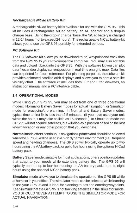
Rechargeable NiCad Battery Kit:
A rechargeable NiCad battery kit is available for use with the GPS 95. Thiskit includes a rechargeable NiCad battery, an AC adaptor and a drop-incharger base. Using the drop-in charger base, the NiCad battery is chargedin 12-14 hours (not to exceed 24 hours). The rechargeable NiCad battery kitallows you to use the GPS 95 portably for extended periods.
PC Software Kit:
The PC Software Kit allows you to download route, waypoint and track datafrom the GPS 95 to your PC-compatible computer. You may also edit thisdata and upload it back into the GPS 95. With the software kit you can plotdata files and/or display current position in real-time on a grid map. Data filescan be printed for future reference. For planning purposes, the software kitprovides animated satellite orbit displays and allows you to print a satellitevisibility chart. The software kit includes both 3.5" and 5.25" diskettes, aninstruction manual and a PC interface cable.
1.4 OPERATIONAL MODES
While using your GPS 95, you may select from one of three operationalmodes: Normal or Battery Saver modes for actual navigation, or Simulatormode for practicing/trip planning. In Normal and Battery Saver modes,typical time to first fix is less than 2.5 minutes. (If you have used your unitwithin the hour, it may take as little as 15 seconds.) In Simulator mode theGPS 95 will not acquire satellites, but will display a position based on the lastknown location or any other position that you designate.
Normal mode offers continuous navigation updates and should be selectedwhen the GPS 95 will be used in a high dynamics environment (i.e., frequentspeed and heading changes). The GPS 95 will typically operate up to twohours using the AA battery pack, or up to five hours using the optional NiCadbattery pack.
Battery Saver mode, suitable for most applications, offers position updatesthat adapt to your needs while extending battery life. The GPS 95 willtypically operate up to four hours using the AA battery pack, or up to eighthours using the optional NiCad battery pack.
Simulator mode allows you to simulate the operation of the GPS 95 whileat home or in your office. The simulator mode can be selected while learningto use your GPS 95 and is ideal for planning routes and entering waypoints.Keep in mind that the GPS 95 is not tracking satellites in the simulator mode.YOU SHOULD NEVER ATTEMPT TO USE THE SIMULATOR MODE FORACTUAL NAVIGATION.

2-1
STAT
STO
ABC1
JKL4
STU7 9
MNO5
VWX8
0
DEF2
GHI3
PQR6
YZ-
NAV
RTE
ENT
WPT
CLR
PWR
GOTO
AUTO
TINA STINKS
Softkeys
Page Annunciator
CHAPTER 2
GETTING STARTED
2.1 FRONT PANEL
The front panel consists of a 20-key keypad with a 85 x 64-pixel LCD display.Both the display and keypad may be illuminated for nighttime operation.
2.2 SOFTKEY OPERATION
Information displayed on the LCD is commonly referred to as a “page.” TheGPS 95 works with softkey operation. At the bottom of the screen is a list ofpage options. To select a different page, press the appropriate softkey belowthe desired option. Please note that the page options must be highlighted inorder to use the softkeys. On the bottom line, extreme right, is the pageannunciator which indicates the current page you are viewing.
Message Annunciator
Page Options

2-2
2.3 CURSOR AND FIELDS
The area of the page which is highlighted in reverse video is called thecursor . The cursor may be moved to locations on the page called fieldswhich allow you to enter data or change options. You will encounter five typesof fields.
· Numeric fields accept numbers only.
· Alphanumeric fields accept numbers as well as letters.
· Cyclic fields allow selection from several available options. A cyclicfield is preceded by a prompt ( ). You may cycle through the choicesby pushing CLR.
· Confirmation fields allow you to indicate your approval. For example,you will be asked to confirm that you want to delete a waypoint.Confirmation fields always end with a “?” character. Press ENT toapprove the confirmation field.
· Bar fields allow an adjustable scale entry with the length of the barrepresenting the minimum to maximum setting. Use the arrow keys tomake adjustments in bar fields.
2.4 KEYPAD OPERATION
The PWR/STAT key is a dual function key that controls unit powerand system status. Pressing this when the unit is off will turn theunit on. To turn the unit off, press and hold PWR/STAT until thedisplay is blank.
Pressing PWR/STAT momentarily while the unit is on will take youto the status pages. (See Chapter 8.) If the message annunciatoris flashing and the tone sounds, you may push PWR/STAT to viewthe message.
Cyclic Field Confirmation Field Bar Field
STATPWR

2-3
Pressing GOTO allows you to instantly define a destinationwaypoint and plot a course from present position to thatdestination. (See Chapter 4.)
Pressing AUTOSTOre allows you to capture your presentposition instantaneously. (See Chapter 7.)
Pressing NAV allows you to view position and navigationinformation as well as the Map Display. (See Chapter 5.)
The WPT key allows you to create, edit, delete, and renameuser waypoints. The WPT key also allows you to view nearestwaypoints or define proximity waypoints. (See Chapter 3.)
The RTE key allows you to create, edit, review, activate, anddelete routes. (See Chapter 6.)
Pressing either of the arrow keys allows you to move thecursor, scroll through information lists, and enter lettersof the alphabet.
The alphanumeric keys allow you to enter letters andnumbers. Use the arrow keys to select the desiredletter or number from a given alphanumeric key.
Pressing this key while the cursor is not on a numeric oralphanumeric field allows you to change the backlight level.There are two backlighting levels. On an alphanumeric field,pressing this key allows you to enter a blank space or a zero.
Pressing CLR erases information in the cursor field. If thecursor is over a cyclic field, pressing CLR will toggle throughseveral available options.
Pressing ENT confirms an entry or selection.
NAV
WPT
GOTO
STOAUTO
RTE
ENT
CLR
0

2-4
2.5 ENTERING DATA
You may enter data such as waypoint identifiers and user waypointcoordinates on certain pages. To enter data you must first move thecursor to the desired field by pressing the right or left arrow key. A dataentry operation is completed by pressing the ENT key. If an error is madeduring the data entry process, press the CLR key to remove the erroneouscharacter.
To enter a number...
· Press the key that is labeled with the desired number. The numberswill fill in from the right side of the field and move to the left as eachnew number is entered. For example, if you wish to enter “51” in athree space field, you must press the 5 and 1 keys in that order. Youdo not have to enter a leading zero. (Note: When entering numbersin an alphanumeric field press the key that is labeled with thedesired number, then press the right or left arrow key twice.)
· Press CLR if you enter an incorrect number.
· Press ENT when you have filled all significant digits of the field withnumbers.
To enter a letter...
· Press the key that is labeled with the desired letter.
· Press the right or left arrow key until the desired letter is displayed.
· Press CLR if you enter an incorrect letter.
· Press ENT when all the characters are entered.
The GPS 95 features a keypad feedback tone which will sound each timeyou press a key. If you enter data which is not appropriate for the field, thefeedback tone will quickly sound three times indicating an error. Thekeypad feedback tone can be turned off if you wish. (See Section 8.10.)

2-5
2.6 VIEWING MESSAGES
From time to time, the GPS 95 will use a message to tell you of conditionsneeding attention. When the GPS 95 has a new message, the MSGannunciator will flash. When this occurs, press PWR/STAT to view the newmessage(s). Press PWR/STAT again to see the page you were viewing priorto reading the message. (See Appendix A for a complete list of GPS 95messages.)
While the MSG annunciator is flashing, the GPS 95 will also generate a toneto alert you of the message. (If your unit is connected to an external alarm,it will also be activated.) Messages that demand immediate attention suchas an arrival alarm generate a quick tone that will not stop until you view themessage. All other messages generate a slow tone that will cease after 15seconds. The message tone may be turned off if you wish. (See Section8.10.)
Important messages will remain on the Message Page after being viewed.If this occurs, the MSG annunciator will be in view but will not flash. (If nomessages exist, the MSG annunciator will not be visible.) To review thesemessages, press PWR/STAT to reveal the status menu options. Then pressthe key underneath the “AUX” page option. With the arrow keys, highlight“Messages” and press ENT.
2.7 TURNING THE GPS 95 ON
When the GPS 95 is turned on it will automatically perform internal checksto ensure proper operation, begin acquiring satellites, and once a sufficientnumber are received, display your present position. To see this power onsequence, take the GPS 95 outside to a location that is well away frombuildings and other structures that might limit its view of the sky.
After you turn your GPS 95 on, it will conduct a series of self tests and displaythe following notice:
2-6
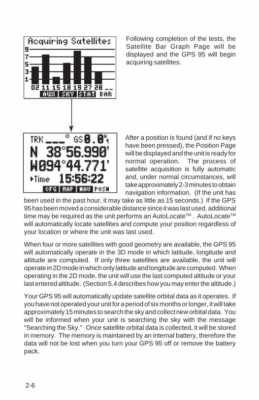
Following completion of the tests, theSatellite Bar Graph Page will bedisplayed and the GPS 95 will beginacquiring satellites.
After a position is found (and if no keyshave been pressed), the Position Pagewill be displayed and the unit is ready fornormal operation. The process ofsatellite acquisition is fully automaticand, under normal circumstances, willtake approximately 2-3 minutes to obtainnavigation information. (If the unit has
been used in the past hour, it may take as little as 15 seconds.) If the GPS95 has been moved a considerable distance since it was last used, additionaltime may be required as the unit performs an AutoLocateTM . AutoLocateTM
will automatically locate satellites and compute your position regardless ofyour location or where the unit was last used.
When four or more satellites with good geometry are available, the GPS 95will automatically operate in the 3D mode in which latitude, longitude andaltitude are computed. If only three satellites are available, the unit willoperate in 2D mode in which only latitude and longitude are computed. Whenoperating in the 2D mode, the unit will use the last computed altitude or yourlast entered altitude. (Section 5.4 describes how you may enter the altitude.)
Your GPS 95 will automatically update satellite orbital data as it operates. Ifyou have not operated your unit for a period of six months or longer, it will takeapproximately 15 minutes to search the sky and collect new orbital data. Youwill be informed when your unit is searching the sky with the message“Searching the Sky.” Once satellite orbital data is collected, it will be storedin memory. The memory is maintained by an internal battery, therefore thedata will not be lost when you turn your GPS 95 off or remove the batterypack.

2-7
If the GPS 95 cannot acquire enough satellites for 2D or 3D navigation, youwill be informed with the message “Poor GPS coverage”. If this situationoccurs, make sure the antenna is properly connected and not obstructed bynearby buildings or other structures.
2.8 TURNING THE GPS 95 OFF
To turn the GPS 95 off, press and holdthe PWR/STAT key.
The Off Page will be displayed, the GPS95 will perform a countdown and, after abrief delay, will shut off. All userwaypoints, routes, and setup informationthat you have entered will be maintainedwhile the unit is off - even if the batterypack is removed.
2.9 LEARNING TO USE THE GPS 95
If you are using the GPS 95 for the first time, you are encouraged to readChapter 3 which introduces the GPS 95's waypoint features, Chapter 4 onthe use of the GOTO key, and Chapter 5 for navigating to a waypoint. Asample trip is included in Chapter 5 to get you started on the use of the GOTOkey and the various navigation pages available on your GPS 95. You mayalso want to read Chapter 8 on custom setups to configure the GPS 95 to yourpreferences. Afterward, you may want to read through the rest of this manualand make further use of the built-in simulator to practice with the advancedfeatures.

3-1
CHAPTER 3
WAYPOINTS
The GPS 95 allows you to store up to 500 user waypoints. A basic waypointconsists of an identifier (up to six letters and/or numbers) and its location.You will have the opportunity to use waypoints extensively while operatingthe GPS 95. For example, you can build a route using waypoints, you canperform trip/fuel planning using waypoints, and you can even calculate thetime of sunrise and sunset for a waypoint of interest.
The GPS 95 features four primary waypoint pages. You may select thedesired page by pressing WPT and, if needed, the appropriate softkey.
Proximity Waypoint Page Waypoint List Page
Nearest Waypoint Page Waypoint Definition Page
WPT

3-2
3.1 WAYPOINT DEFINITION PAGE
The Waypoint Definition Page allows you to create, edit and review waypointinformation.
This page displays the following waypoint information:
1) Waypoint identifier
2) Location (latitude/longitude or grid system)
3) Reference waypoint identifier
4) Bearing from reference waypoint to selected waypoint
5) Distance from reference waypoint to selected waypoint
6) User comments
Waypoints are selected by the identifier that you assign.
To select a waypoint...
· Press WPT and, if needed, the WPT softkey to display the WaypointDefinition Page.
· Press the right arrow key to move the cursor to the right of “WPT”.
· Enter the identifier of the desired waypoint using the alphanumeric andarrow keys. Press ENT. The information for the selected waypoint isdisplayed.
You may select a reference waypoint by moving the cursor to the referencewaypoint identifier field and entering the desired waypoint identifier.
1
54
2
3
6

3-3
3.2 CREATING WAYPOINTS
When a waypoint identifier has been entered that does not exist in memorythe GPS 95 will assume you wish to create a new waypoint. You may createa new waypoint using one of two methods: direct position entry (latitude/longitude or grid system) or relative to an existing waypoint.
In order to create a waypoint by direct position entry the coordinates for thenew waypoint must be known and entered directly into the unit.
To enter the waypoint position directly...
· With the Waypoint Definition Page displayed, press the right arrow keyuntil the cursor is over the waypoint identifier field.
· Enter the identifier of the new waypoint using the alphanumeric andarrow keys. Press ENT when complete. The cursor will move to theposition coordinates.
· Enter the position of the new waypoint. Press ENT after data is enteredinto each field. The number of fields required for position entry willdepend on the position coordinate option selected. (See Section 8.7.)If latitude and longitude coordinates are selected there will be fourfields if decimal degrees are used - two to define the hemispheres (“N”or “S”, “E” or “W”) and two to enter the latitude and longitude degrees.If latitude and longitude coordinates are selected with degrees, minutesand decimal seconds, there will be eight data entry fields to define theposition since degrees, minutes and seconds are each divided intotheir own field. If a grid system is selected it will have a different numberof fields depending on the format of the selected grid.
A new waypoint can be defined relative to another waypoint alreadycontained within the GPS 95's memory. When creating a new waypointrelative to an existing waypoint, you will define a distance and bearing fromthe existing waypoint to the new waypoint location.

3-4
To create a waypoint offset from a reference waypoint...
· With the Waypoint Definition Page displayed, press the right arrow keyuntil the cursor is over the waypoint identifier field.
· Enter the identifier of the new waypoint using the alphanumeric andarrow keys. Press ENT when complete.
· Press the right arrow key until the cursor is over the reference waypointidentifier field.
· Enter the identifier of the desired reference waypoint and press ENT.
· Enter the bearing from the reference waypoint to the new waypointand press ENT. The bearing will be true or magnetic depending on theunit setups. (See Section 8.7.)
· Enter the distance from the reference waypoint to the new waypointand press ENT. The distance will be in nautical miles, statute miles orkilometers depending on the unit setups. (See Section 8.7.)
Once the waypoint location is created, the user comment field will automaticallybe filled with the date and time the waypoint was created. You may enter adifferent user comment by placing the cursor over this field and entering thenew comment with the alphanumeric and arrow keys, followed by ENT whencomplete.
You may also modify the position of an existing waypoint from the WaypointDefinition Page. A waypoint may be changed using the same proceduresdescribed above for creating a waypoint, by direct position entry (latitude/longitude or grid system) or relative to an existing waypoint. When modifyingan existing waypoint, the new position data is entered directly over the olddata. For a given data field, once the ENT key is pressed the position datais updated. (NOTE: If a waypoint is being used for navigation, its positioncannot be modified. An attempt to modify the position of such a waypoint willresult in the message “Cannot change active waypoint”.)

3-5
3.3 WAYPOINT LIST
The Waypoint List Page allows you to view all stored waypoints in your GPS95. The list may be scrolled, with the arrow keys, to view all the waypoints.From this page, waypoints may be selected for deletion, renaming or toactivate a GOTO. (See Chapter 4 for information on the GOTO function.)
To delete a waypoint...
· Select the Waypoint List Page by pressing WPT and the LIST softkey,if needed.
· With the arrow keys, place the cursor on the desired waypoint.
· Press CLR and ENT.
· A confirmation page is displayed. Press ENT to confirm or CLR tocancel.
NOTE: If you attempt to delete a proximity or route waypoint, a message willbe displayed. You must delete the proximity alarm or the route before youcan delete the waypoint. (See Sections 3.6 and 6.5.)
The Waypoint List Page also gives you the option of deleting all waypointsat one time.
To delete all waypoints...
· Select the Waypoint List Page by pressing WPT and the LIST softkey,if needed.
· With the arrow keys, place the cursor over “Delete All?” and pressENT.
· A confirmation page is displayed. Press ENT to confirm the deletionof all waypoints or CLR to cancel.

3-6
NOTE: The “Delete All?” selection will delete all routes and proximitywaypoints as well.
From the Waypoint List Page you may also change the name of anywaypoint.
To rename a waypoint...
· Select the Waypoint List Page by pressing WPT and the LIST softkey,if needed.
· With the arrow keys, place the cursor on the desired waypoint.
· Type in a new name for the waypoint and press ENT.
· A confirmation page is displayed. Press ENT to confirm the namechange or CLR to cancel.
3.4 USING WAYPOINTS
You may use waypoints on many GPS 95 pages. A waypoint is selected byentering its identifier and pressing ENT.
The GPS 95 also offers a waypoint scanning feature which will simplifywaypoint entry. When scanning, the nine nearest waypoints will be displayedfirst, followed by the entire list.
To select a waypoint by scanning identifiers...
· On a blank waypoint identifier field press the WPT key. (If the identifierfield is not blank, press CLR first.)
· Press the right arrow key to sequence through the available waypoints.If you pass the desired waypoint, you may press the left arrow key toscan backwards through the list.
· Once the desired waypoint is selected, press ENT to accept thewaypoint and complete the scan. The selected waypoint will bedisplayed on the waypoint identifier field.
You may limit the scan by defining the starting letter, or letters, where youwish the scan to begin. Limited scanning can save considerable time whena large number of waypoints have been added to memory.
3-7
To select a waypoint using a limited scan...
· Select a blank waypoint identifier field. (If the identifier field is not blank,press CLR first.)
· Enter the starting letter, or letters, of the desired waypoint identifier.You may limit the scan to the level that you desire. For example, if youenter “C” the GPS 95 will scan through all waypoints that begin with theletter “C”, but, if you enter “CRY” the GPS 95 will display only thosewaypoints that begin with “CRY”.
· Press WPT to begin scanning.
· Press the right arrow key to sequence through the available waypoints.If you pass the desired waypoint, you may press the left arrow key toscan backwards through the list.
· Once the desired waypoint is selected, press ENT to accept thewaypoint and complete the scan. The selected waypoint will bedisplayed on the waypoint identifier field.
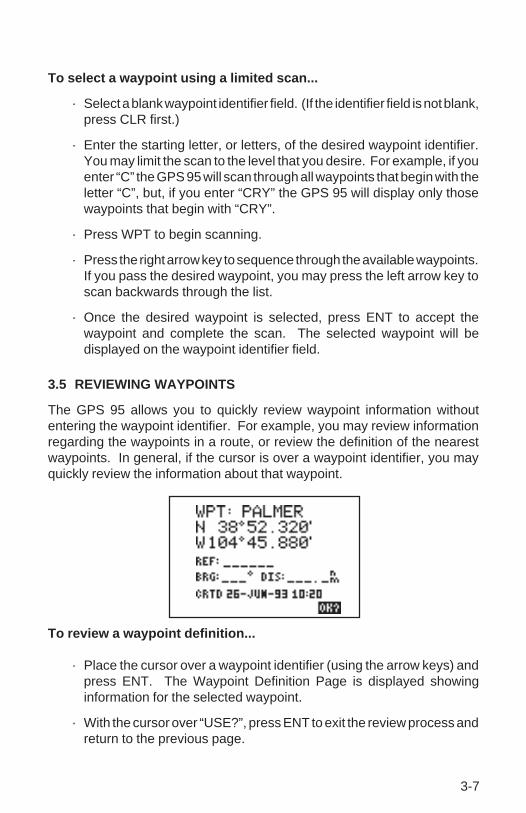
3.5 REVIEWING WAYPOINTS
The GPS 95 allows you to quickly review waypoint information withoutentering the waypoint identifier. For example, you may review informationregarding the waypoints in a route, or review the definition of the nearestwaypoints. In general, if the cursor is over a waypoint identifier, you mayquickly review the information about that waypoint.
To review a waypoint definition...
· Place the cursor over a waypoint identifier (using the arrow keys) andpress ENT. The Waypoint Definition Page is displayed showinginformation for the selected waypoint.
· With the cursor over “USE?”, press ENT to exit the review process andreturn to the previous page.

3-8
3.6 PROXIMITY ALARM WAYPOINTS
The Proximity Waypoint Page allows you to define an alarm circle arounda waypoint. This feature is useful in defining an area around a TCA (ClassB), MOA, tower, etc. When you approach one of these waypoints the GPS95 will notify you with an alarm tone and the message, “Prox Alarm -[waypoint name],” if you enter the alarm circle.
The GPS 95 allows you to define a maximum of nine proximity waypoints.Scroll through the proximity waypoint list using the arrow keys.
To set a proximity waypoint...
· Select the Proximity Waypoint Page by pressing WPT and the PROXsoftkey, if needed.
· Place the cursor on a blank waypoint identifier field using the arrowkeys.
· Enter the identifier of the desired waypoint and press ENT. (NOTE: Ifneither the waypoint name nor the location exists in memory, theWaypoint Definition Page will be displayed. You must then enter thewaypoint location.)
· Enter the proximity alarm distance and press ENT. The proximityalarm distance defines a radius from the waypoint.
If the newly created proximity alarm circle overlaps with an existing proximityalarm circle, you will be informed of the overlap with the message “ProximityOverlap”. As long as the overlap remains this message will be displayedeach time the GPS 95 is turned on. (WARNING: If you enter the overlap areathe unit will only inform you of the nearest waypoint.)

3-9
3.7 NEAREST WAYPOINTS
An important feature on the GPS 95 is the ability to display up to nine nearestwaypoints within 200 nautical miles of your present position. The bearing anddistance to each nearest waypoint is also displayed. The nearest waypointfeature can be critical in finding a safe landing location in the event of an in-flight emergency.
To view nearest waypoint information...
· Select the Nearest Waypoint Page by pressing WPT and the NRSTsoftkey, if needed. The six nearest waypoints will be displayed, alongwith the bearing and distance to each.
· Use the arrow keys to scroll through the list and view additional nearestwaypoints (up to nine).
Keep in mind that you may view additional information for any nearestwaypoint by placing the cursor on the waypoint identifier and pressing ENT.
The nearest waypoint feature can be used in conjunction with the GOTO keyto provide instantaneous navigation information to a nearby waypoint.Simply place the cursor over the desired nearest waypoint identifier andpress GOTO, followed by ENT. The GPS 95 will immediately plot a coursefrom your present position to the nearby waypoint. (See Chapter 4 for moreinformation on the GOTO key.)

4-1
CHAPTER 4GETTING THERE FAST - GOTO
The GOTO function allows you to quickly set a course from your position toany waypoint.
To activate the GOTO function...
· Press GOTO. The GOTO Page will be displayed with the cursor onthe GOTO waypoint field. If the GPS 95 is currently navigating to awaypoint, that waypoint will be offered as the default GOTO waypoint.If the waypoint field is blank or the waypoint shown is not the desireddestination, type the new name right over the old name. NOTE: If anon-existent waypoint name is entered, the GPS 95 will assume thatthis is a new waypoint and will display a blank Waypoint DefinitionPage where you may enter the new waypoint's coordinates.
· Confirm the GOTO waypoint by pressing ENT. The NavigationSummary Page will be displayed with the D-bar on the CDI centered.(See Section 5.1 for more information on the Navigation SummaryPage and the CDI.)
You may also select the desired GOTO waypoint identifier by scanning. (SeeSection 3.4 for more information on waypoint scanning.) Alternatively, theGOTO function may be quickly activated from any page (e.g., the NearestWaypoint Page or the Waypoint List Page) by placing the cursor over thedesired waypoint name and pressing GOTO. The GOTO Page will bedisplayed with the cursor on the GOTO waypoint name. The GOTO functionwill be activated when the ENT key is pressed.
You may cancel the GOTO function at any time.

4-2
To cancel the GOTO function...
· Press GOTO. The GOTO Page will be displayed.
· Press CLR. The GOTO waypoint name will become blank.
· Press ENT. The GPS 95 will start to navigate using the active route,if it has been programmed. (See Chapter 6.) Otherwise, the GPS 95will stop computing waypoint navigation data.

5-1
CHAPTER 5
NAVIGATION INFORMATION
The GPS 95 features four navigation pages. You may select the desiredpage by pressing NAV and, if needed, the appropriate softkey.
5.1 NAVIGATION SUMMARY PAGE
Present Position Page
Map Configuration Page
Field #3
CDI
Field #4
Field #2
GOTO orActive Leg
Field #1
Relative BearingPointer
Navigation Summary Page
Map Display
NAV

5-2
The Navigation Summary Page displays direction, distance and speedinformation to guide you along a route or to a GOTO destination. Includedis a graphic course deviation indicator (CDI), at the bottom of the page, whichillustrates your position relative to the course. The current CDI scale settingis shown at each end of the CDI scale. (See Section 8.8 for information onsetting the CDI scale.) A relative bearing pointer at the center of the CDIindicates the bearing to the waypoint relative to the current ground track(TRK). In the example shown, the current ground track is 347 degrees andthe bearing to our destination is 339 degrees. The relative bearing pointerpoints slightly to the left indicating that our destination is ahead, but slightlyto the left of our current direction of travel.
At the top of the Navigation Summary Page the current GOTO destination isdisplayed, or the “active leg” of a route when using the GPS 95’s routenavigation features. (See Chapter 6 for information on route navigation.)During the process of acquiring satellites, the GPS 95 will not providenavigation data. The top line of the Navigation Summary Page will indicatethis condition, as illustrated below.
If the GPS 95 has acquired satellites, but is not navigating to a waypoint (i.e.,no GOTO destination or route has been activated), the top line of theNavigation Summary Page will indicate that no destination has been defined,as illustrated below.

5-3
Scale Setting
Notice that the Navigation Summary Page has four cyclic fields. With thesecyclic fields you may configure your GPS 95 to display navigation informationaccording to your preferences. (See Appendix B for a description ofnavigation terms.) The field options are as follows:
Field #1 (top left)
· Bearing to destination waypoint (BRG)· Course to steer (CTS)· Desired track (DTK)· Ground track (TRK)· Off course error, or turn angle (TRN)
Field #2 (top right)
· Distance to destination waypoint (DIS)· Cross track error (XTK)· VNAV altitude (V)
Field #3 (bottom left)
· Ground track (TRK)· Ground speed (GS)
Field #3 (bottom right)
· Ground speed (GS)· Estimated time of arrival (ETA)· Estimated time enroute (ETE)
5.2 MAP DISPLAY
Ground Speed
Present Position
Map Orientation

5-4
The GPS 95 also features a Map Display which shows a graphic top view ofyour location. The current ground speed is indicated at the top right cornerof the display. The top left corner defines the orientation of the Map Display:“North up”, “Ground track up”, or “Desired track up.” If “000” is shown, theMap Display is oriented “North up.” (See Section 5.3 for selection of MapDisplay orientation.) Your present position is shown in the middle of thedisplay. If the Map Display is oriented “Ground track up” your presentposition is indicated by an aircraft symbol. If either “North up” or “Desiredtrack up” orientations are selected, the present position is indicated by acrosshair (“+”).
You may select which items you wish to display. The Map Display canprovide up to nine nearest waypoints. GOTO or route waypoints which arenot part of the nine nearest waypoints will also be displayed. The track historyand/or the active route may also be shown as solid lines on the display.Selection of which items to display is performed on the Map ConfigurationPage. (See Section 5.3.)
You may view the identifier for any waypoint on the Map Display by movingthe cursor over that waypoint (with the arrow keys). By moving the cursoraround the page you can identify each waypoint shown. Keep in mind thatwhen the cursor is over a waypoint identifier you may review informationabout that waypoint by pressing ENT, or plot a course to that waypoint bypressing GOTO.
The scale distance for the screen (distance represented by the height of thescreen) is at the lower left corner of the screen. The scale number (directlyabove the scale distance) may be changed to the level that you desire. Youmay zoom in to a .5 nautical mile scale, or out to a maximum scale of 240nautical miles.
Waypoint highlighted(w/identifier)
Waypoints

5-5
To set the Map Display scale...
· Press the left arrow key to place the cursor on the scale number.
· Press CLR to sequence through the available scale settings. (HINT:The scale setting may also be selected by pressing the alphanumerickey that corresponds to the desired scale.)
5.3 MAP CONFIGURATION
The Map Configuration Page allows you to tailor the GPS 95’s Map Displayto your preferences. As previously stated, the Map Display can showwaypoints, the active route, your track history and/or waypoint identifiers.Any of these items may be turned on or off according to your preferences.For example, when the Map Display is zoomed out to its maximum levels thescreen may appear too cluttered to be easily read. In this case, you couldturn off the information not needed to create a more legible display.
To turn display information on/off...
· Press NAV and the CFG softkey, if needed, to select the MapConfiguration Page.
· Place the cursor on the desired item using the arrow keys.
· Press CLR to toggle between “on” and “off”.
· If you wish to return to the Map Display: place the cursor on the menubar using the arrow keys, then press the MAP softkey.
5-6
The Map Display orientation is also selected from the Map ConfigurationPage. The Map Display may be oriented as follows:
· North up - The Map Display will always be displayed with north as thetop of the page.
· TRK up - Track up. The Map Display will be oriented such that yourcurrent ground track direction is at the top of the page.
· DTK up - Desired track up. The Map Display will be oriented alongthe course between the “active from” and “active to” waypoints.
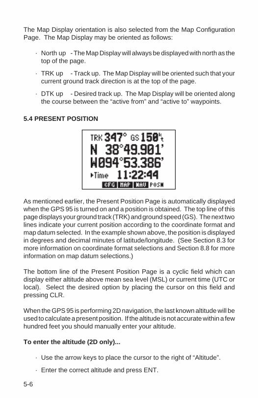
5.4 PRESENT POSITION
As mentioned earlier, the Present Position Page is automatically displayedwhen the GPS 95 is turned on and a position is obtained. The top line of thispage displays your ground track (TRK) and ground speed (GS). The next twolines indicate your current position according to the coordinate format andmap datum selected. In the example shown above, the position is displayedin degrees and decimal minutes of latitude/longitude. (See Section 8.3 formore information on coordinate format selections and Section 8.8 for moreinformation on map datum selections.)
The bottom line of the Present Position Page is a cyclic field which candisplay either altitude above mean sea level (MSL) or current time (UTC orlocal). Select the desired option by placing the cursor on this field andpressing CLR.
When the GPS 95 is performing 2D navigation, the last known altitude will beused to calculate a present position. If the altitude is not accurate within a fewhundred feet you should manually enter your altitude.
To enter the altitude (2D only)...
· Use the arrow keys to place the cursor to the right of “Altitude”.
· Enter the correct altitude and press ENT.

5-7
During the initial satellite acquisition, the displayed position is the last knownposition stored in the GPS 95. If your position has moved a considerabledistance since the unit was last used, the GPS will perform an AutoLocateTM
(See Section 2.7.) This process can take up to ten minutes as the GPS 95determines its new location. Alternatively, you may enter a more accurateinitial position directly on the Present Position Page to speed up theacquisition process. (You may also change the position at any time while youare in simulator mode.)
5.5 SAMPLE TRIP
Your new GPS 95 is really very simple to operate. For the purpose of thisdemonstration is assumed that the factory default settings, including theselection of nautical units (knots, nautical miles, feet), have not beenchanged. If these settings have been changed, the unit may display differentdata than that presented here. (See Chapter 8 on unit setups.)
Turn the GPS 95 on. The unit willdisplay the welcome screen andperform several diagnostic checks toensure that proper operation will occur.
The Satellite Bar Graph Page will bedisplayed and the GPS 95 will begin toacquire satellites.
Since this is a simulated trip, you will select the simulator mode and indicatea starting location for the trip. Your simulated trip will begin at a waypointcalled GARMIN in Lenexa, Kansas.

5-8
ABC1
ENT
CLR
ENT
*Repeat until desired
mode is selected
To select simulator mode and define a starting location...
Press the AUX softkey (the “1” key, inthis case) to display the Auxiliary Menu.
Place the cursor on “OP Mode” usingthe right arrow key and press ENT.
The Operating Mode Page is displayedshowing the current operational mode.
Place the cursor on the operationalmode field using the right arrow key.
Press CLR until “Simulator?” isselected.
Press ENT to accept simulator mode.
The cursor is now on the referencewaypoint identifier. The waypoint,GARMIN, will be entered here usingthe alphanumeric keys.

5-9
*Press alphanumeric and
arrow keys, as needed, to
select desired identifier
Press the “3” key, followed by the leftarrow key to select the letter “G”.
Press the “1” key followed by the leftarrow key, to select the letter “A”.
Continue pressing the desiredalphanumeric keys and, if needed, thearrow keys to enter the “GARMIN”waypoint. Press ENT when complete.(NOTE: If the GARMIN waypoint isnot in memory its coordinates must beentered to initialize the GPS 95 to thatlocation. Select the Present PositionPage and enter the coordinates forGARMIN [N 38° 57.003' W 94°44.767'].)
The cursor is over the referencebearing. Since the simulation will beginat GARMIN you do not need to definea reference bearing from this point.Press ENT.
The cursor is over the referencedistance. Enter a distance of zero andpress ENT. The initial position is nowset at the GARMIN waypoint.
You can view your position coordinatesby pressing NAV and the POSNsoftkey, if needed. The PresentPosition Page is displayed.
NAV
ENT
ENT
0
ENT
*Plus POSN softkey
if needed
GHI3
ABC1

5-10
WPT*Plus WPT softkey, if
needed
JKL4
ABC1
From your starting location at the “GARMIN” waypoint you may plot a courseand navigate to a nearby airport. For this sample trip you will fly to KCOU,Columbia Regional Airport (N38° 49.078' W92° 13.175'). Before you cannavigate to this waypoint it must be added to the GPS 95's memory.
To create the “KCOU” waypoint...
Press WPT and the WPT softkey, ifneeded, to select the WaypointDefinition Page.
Press the right arrow key to place thecursor on the waypoint identifier field.
Enter the waypoint identifier, KCOU,using the alphanumeric and arrowkeys. Begin by pressing the “4” key toselect the letter “K”.
Press the “1” key, followed by the rightarrow key, to select the letter “C”.
Continue pressing the alphanumericand, if needed, arrow keys until thewaypoint identifier has been entered.Press ENT when complete.
*Continue pressing the
alphanumeric and arrow
keys, if needed, to select
waypoint identifierENT

5-11
Enter the latitude of KCOU (N38°49.078'). Begin by selecting the properhemisphere. If “N” for north is notdisplayed, press CLR.
Press ENT when the properhemisphere is selected.
Enter the latitude degrees. Press the“3” key and the “8” key. Press ENTwhen complete.
Enter the latitude minutes. Begin bypressing the “4” key.
Continue pressing the alphanumerickeys until the latitude minutes havebeen entered. Press ENT whencomplete.
Enter the longitude of KCOU (W92°13.175') in the same manner as wasused for the latitude. Press ENT afterentering data into each field. (NOTE:You do not need to enter the leadingzero for degrees. You may begin bypressing the “9” key.)
ENT
GHI3
CLR
VWX8
ENT
JKL4
*Continue pressing the
alphanumeric keys to
enter the latitude minutes
*If need to select proper
hemisphere
ENT
ENT
*Enter the longitude using
the same steps shown
above
5-12
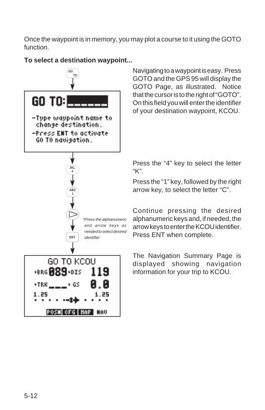
Once the waypoint is in memory, you may plot a course to it using the GOTOfunction.
To select a destination waypoint...
Navigating to a waypoint is easy. PressGOTO and the GPS 95 will display theGOTO Page, as illustrated. Noticethat the cursor is to the right of “GOTO”.On this field you will enter the identifierof your destination waypoint, KCOU.
Press the “4” key to select the letter“K”.
Press the “1” key, followed by the rightarrow key, to select the letter “C”.
Continue pressing the desiredalphanumeric keys and, if needed, thearrow keys to enter the KCOU identifier.Press ENT when complete.
The Navigation Summary Page isdisplayed showing navigationinformation for your trip to KCOU.
*Press the alphanumeric
and arrow keys as
needed to select desired
identifier
GOTO
ENT
JKL4
ABC1

5-13
The GPS 95's simulator mode allows you to enter a ground speed which isused to animate the navigation displays.
To enter a simulated speed...
Press the left arrow key to place thecursor on the ground speed field(bottom right).
Enter a ground speed of 150 knots.Begin by pressing the “1” key. Continuepressing the alphanumeric keys until“150” is displayed. Press ENT whenfinished.
The GPS 95 now displays additionalnavigation information as it simulatesa flight to KCOU. Notice the informationchanging as the flight progresses.
Additional information is available fromthe Navigation Summary Page. You may recall from Section 5.1 that thisinformation is viewed by highlighting one of the four cyclic fields and pressingCLR. Take a look at one of those fields now.
To view additional navigation information...
Press the left arrow key twice to placethe cursor on the fourth cyclic field(bottom right).
Press CLR to select “ETA”. This fieldwill now show at what time (UTC) youwill arrive at Columbia Regional Airport.
The GPS 95's Map Display is also
ENT
ABC1
CLR
*Continue pressing the
alphanumeric keys as
needed to enter ground
speed

5-14
useful to help “orient” yourself. The Map Display can show nearby waypointsas points of reference.
To view the Map Display...
Press NAV.
The Map Display is shown indicatingyour position at the center of the screenand nearby waypoints.
Press the left arrow key to place thecursor on the scale number.
Press CLR (repeatedly) to select thedesired scale.
The simulated trip has demonstrated only a small portion of the GPS 95'smany features. Take a moment to experiment with your new unit. ReviewChapter 5 covering types of information on the Navigation Summary Pageand the Map Display. Look at waypoint information by taking another glanceat Chapter 3. Read Chapter 6 to learn more about routes. Customize yourunit according to your preferences as described in Chapter 8.
NAV
*Continue pressing
CLR until desired
scale is selectedCLR

6-1
CHAPTER 6
ROUTES
The GPS 95 offers a route navigation feature for you to navigate along a pre-defined sequence of waypoints.
The GPS 95 route capability allows you to create and store twenty routes,numbered 0 through 19, containing up to 30 waypoints each. Routes 1 to 19,the storage routes, can be activated to travel either in the order you enteredthe waypoints or in reverse order. Route 0, the active route, is the route youare navigating. The waypoint toward which you are navigating is called the“active to” waypoint. The waypoint immediately behind you is called the“active from” waypoint. The line that connects the “active from” and “activeto” waypoints is called the “active leg.”
The GPS 95 features automatic leg selection which will select the routesegment closest to your position as the active leg. The GPS 95 also featuresautomatic leg sequencing. As you pass a waypoint in the route, the unit willautomatically select the next waypoint as the “active to” waypoint.
(Active to waypoint)(Active from waypoint)
Active Leg
KSTL
EOS
KTUL
SGFMAP

6-2
There are 3 route pages. You may select the desired page by pressing RTEand, if needed, the appropriate softkey.
6.1 ROUTE DEFINITION
The Route Definition page allows you to create, change, review, copy, andactivate routes. Remember that route 0 is always the active route. If youcreate a route in route 0, you should copy it into an empty storage route (1-19). When you activate a storage route, it will be copied to route 0 foractivation.
Route Definition Page Route List Page
Active Route Page
Leg Distance
D e s i r e dTrack
Route # Field Route Action Field
Waypoint List
RTE

6-3
On the route number field, you may choose between routes 0 through 19 withCLR. Next to this is a route action field which allows you to activate the route,clear the route, copy the route to another location, or invert the order of thewaypoints in a route and activate it. The arrow keys allow you to scrollthrough the list of waypoints in a route.
6.2 CREATING AND COPYING ROUTES
The Route Definition Page allows you to create new routes and to copy aroute to another location for later reference.
To Create a Route...
· Press RTE and, if needed, theRTE softkey to display the RouteDefinition Page.
· Move the cursor to the routenumber field and press CLR untilyou find an empty route. (HINT:Although the route number field isa cyclic field, to speed selectionyou may also enter the desiredroute number using thealphanumeric keys.)
· Place the cursor on the first blank waypoint identifier field using thearrow keys and type in a waypoint you wish to put in the route.
· Press ENT
· Repeat this process for each waypoint you want to add, up to a totalof 30.
To copy a route...
· Press RTE and, if needed, theRTE softkey to display the RouteDefinition Page.
· Highlight the route number fieldwith the cursor and select the routenumber to copy from with CLR.
· Highlight the route action field with the arrow keys and press CLR until“>Copy To>” is displayed.
· A third field now appears in the top right corner. Highlight this field andselect the destination route number with CLR.
· Press ENT. The route is now copied.

6-4
6.3 ACTIVATING AND INVERTING ROUTES
Routes are also activated on the Route Definition Page. You may activateany route in the displayed order, or in reverse order. (NOTE: Remember,when a new route is activated, the previous contents of route 0 will beoverwritten. If you wish to save route 0, be sure to copy it to an empty routefirst.)
To activate a route...
· Press RTE and, if needed, theRTE softkey to display the RouteDefinition Page.
· Highlight the route number fieldwith the cursor and select the routenumber to activate with CLR.
· Highlight the route action field, and with CLR select “>Activate?”.
· Press ENT to activate the route.
To invert a route...· Follow the same steps as above
for activating a route, but select“>Invert?” at the route action field.
· Press ENT to activate the route inan inverted order.
6.4 EDITING ROUTES
Existing routes may be edited from the Route Definition Page.
To Edit an Existing Route...
· Press RTE and, if needed, theRTE softkey to select the RouteDefinition Page.
· Highlight the route number fieldwith the cursor and select the routeyou wish to edit.

6-5
· To insert a waypoint into the route:highlight the waypoint you want toplace the new waypoint in front of,type in the new waypoint identifierand press ENT. The new waypointis added to the route.
· To delete a waypoint from theroute: highlight the waypoint youwish to delete, press CLR andENT.
· If you attempt to add a waypoint to a route that already contains 30waypoints, you will be informed with the message, “Route is Full”.
NOTE: You may also edit a route from the Active Route Page. (See Section6.6.)
6.5 DELETING ROUTES
You may delete an unwanted route from the Route Definition Page.
To delete a route...
· Highlight the route number fieldand select the route you wish todelete with CLR.
· Highlight the route action field andselect “>Clear?” with the CLR key.
· Press ENT to delete the route.
6.6 ACTIVE ROUTE
Active Leg
Waypoint List Cyclic Column:- ETE- ETA- DTK
The Active Route Page displays the waypoints of the active route startingwith the “active from” and “active to” waypoints on the top line. Press theACTV softkey to select this page.
Distance
6-6
The waypoint list displays route waypoints starting with the “active to”waypoint. For each waypoint, additional information is available. The firstcolumn displays Distance (DIS). The second column is a cyclic field thatdisplays Estimated Time Enroute (ETE, in hours/minutes or minutes/seconds,as appropriate), Estimated Time of Arrival (ETA), or Desired Track (DTK).You may scroll through the waypoint list with the arrow keys.
To edit the active route...
· To insert a waypoint: highlight the waypoint you want to place the newwaypoint in front of, type in the new waypoint identifier and press ENT.The new waypoint is added to the route.
· To delete a waypoint: highlight the waypoint you wish to delete, pressCLR and ENT.
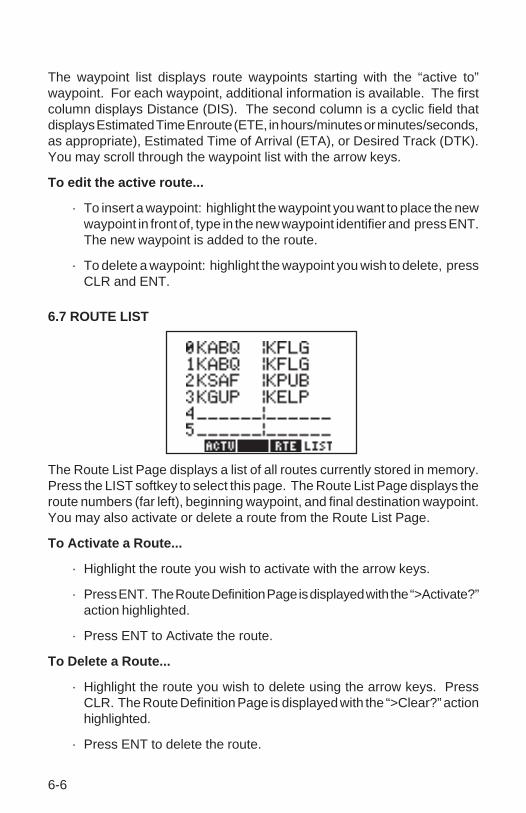
6.7 ROUTE LIST
The Route List Page displays a list of all routes currently stored in memory.Press the LIST softkey to select this page. The Route List Page displays theroute numbers (far left), beginning waypoint, and final destination waypoint.You may also activate or delete a route from the Route List Page.
To Activate a Route...
· Highlight the route you wish to activate with the arrow keys.
· Press ENT. The Route Definition Page is displayed with the “>Activate?”action highlighted.
· Press ENT to Activate the route.
To Delete a Route...
· Highlight the route you wish to delete using the arrow keys. PressCLR. The Route Definition Page is displayed with the “>Clear?” actionhighlighted.
· Press ENT to delete the route.

7-1
CHAPTER 7
AUTOSTORETM
The AutostoreTM function allows you to capture your position at the touch ofa button for future reference. This function saves your current position as awaypoint. Additionally, you may record your navigation path by inserting thecaptured waypoints directly into a route.
The AutostoreTM Page displays the waypoint identifier, captured position andoptional storage route. An AutostoreTM waypoint identifier is pre-assigned asa three digit number. You may change this to any name you desire.AutostoreTM waypoints may be used for any waypoint operation and will bepart of the 500 available waypoints.
7.1 CREATING WAYPOINTS WITH AUTOSTORE TM
Route StorageNumber
CapturedPosition
WaypointIdentifier
STOAUTO

7-2
You may capture and save your position as a waypoint, without adding it toa route, by leaving the route storage number field blank.
To capture present position ...
· Press AUTOSTO. The pre-assigned waypoint identifier and capturedposition are displayed. (NOTE: The AutostoreTM location is capturedas soon as you press AUTOSTO. This allows you all the time you needto change the waypoint identifier and/or confirm the AutostoreTM
operation.)
· If you wish to assign a different identifier to the waypoint: move thecursor to the waypoint identifier field, enter the name of your choice andpress ENT. If you enter a waypoint identifier already used, you will beinformed with the message, “WPT Exists _____” (where the blank willbe filled in with the waypoint identifier). Enter a different identifier if thisoccurs.
· Press ENT on a blank route storage number field to save the waypoint.(If the route storage number field is not blank, the waypoint will beadded to the route shown.)
7.2 BUILDING ROUTES WITH AUTOSTORE TM
The GPS 95’s AutostoreTM feature may also be used to build a route as youare flying. During your flight; as you reach each airport, NAVAID, landmark,or turn to a new heading; you may capture your position and add it to a route.Once you reach your destination you can then invert the route and follow thesame course back to where you started. Or, you may want the route for futurereference if you wish to make the same flight again.

7-3
To build a route with Autostore TM...
· From the starting location, press AUTOSTO to capture the position.(NOTE: The unit must me in 2D or 3D navigation mode when capturingyour starting position. If the unit is still acquiring satellites, and youpress AUTOSTO, the last known position will be captured and saved.)
· If you wish to assign a different identifier to the waypoint: move thecursor to the waypoint identifier field, enter the name of your choiceand press ENT. If you enter a waypoint identifier already used, you willbe informed with the message, “WPT Exists _____” (where the blankwill be filled in with the waypoint identifier). Enter a different identifierif this occurs.
· Select a route to store the waypoint in by highlighting the route storagenumber field and pressing CLR until the desired route number isdisplayed. If the selected route is not empty, the AutostoreTM waypointwill be added to the end of the existing route. (HINT: Although the routestorage number field is a cyclic field, to speed selection you may alsoenter the desired route number using the alphanumeric keys.)
· Press ENT to add the waypoint to the selected route.
· Repeat these steps each time you arrive at a location you wish to addto the route, up to a total of 30 waypoints per route.
8-1
CHAPTER 8
GPS STATUS AND AUXILIARY FUNCTIONS
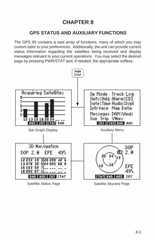
The GPS 95 contains a vast array of functions, many of which you maycustom tailor to your preferences. Additionally, the unit can provide currentstatus information regarding the satellites being received and displaymessages relevant to your current operations. You may select the desiredpage by pressing PWR/STAT and, if needed, the appropriate softkey.
Bar Graph Display Auxiliary Menu
Satellite Skyview PageSatellite Status Page
STATPWR

8-2
8.1 BAR GRAPH DISPLAY
The GPS 95 continually monitors thestatus of the satellites it tracks andshows that information graphically on aBar Graph Display. Satellite numbers(1-32) are represented along the bottomof the graph; signal strength (1 to 9,weakest to strongest) is representedalong the side. Once a satellite isreceived, a bar is displayed showing
signal strength for that satellite. If a satellite is visible, but not being received,the signal strength will be blank.
The receiver status is also shown at the top of the page. In this example, theunit is acquiring satellites. The following is a list of possible receiver statusmessages:
“Searching the Sky” The GPS 95 is in the process of searching thesky for visible satellites. You will also beinformed of this condition with a “Searchingthe Sky” message.
“Acquiring Satellites” The GPS 95 is in the process of acquiringvisible satellites.
“2D Navigation” The GPS 95 is in the 2D navigation mode.The unit will calculate a horizontal position,but not altitude.
“3D Navigation” The GPS 95 is in the 3D navigation mode andwill calculate altitude
“Simulating Navigation” The GPS 95 is in the simulator mode. Thismode should be used only for practice and tripplanning. Never use this mode for actualnavigation.
“Poor Coverage” The GPS 95 is unable to acquire sufficientsatellites for navigation.
“Need Altitude” The GPS 95 needs altitude in order to startand/or continue 2D navigation. Go to thePresent Position Page and enter the altitude.(See Section 5.4.)

8-3
“Not Usable” The GPS 95 is unusable (possibly due toincorrect initialization data or abnormal satelliteconditions). Turn the unit off and back on.
When operating with an RTCM inputselected, the Bar Graph Display willdenote each satellite for whichdifferential corrections are availablewith a “D” at the bottom of the bar.(See Section 8.11 for more informationon RTCM input selections.)Furthermore, the differential navigationstatus will also display at the top of the
page. There are two additional receiver status messages available whenusing an RTCM input:
“2D Nav - Diff”” The GPS 95 has calculated a differentially-corrected horizontal position. Altitude has notbeen corrected.
“3D Nav - Diff”” The GPS 95 has calculated a differentially-corrected position, including altitude.
8.2 SATELLITE STATUS PAGE
The Satellite Status Page shows the ID,azimuth, elevation, and signal quality ofeach visible satellite in a table format.The receiver status, again, is displayedat the top of the screen. The second linedisplays two system quality values -dilution of precision (DOP) and estimatedposition error (EPE). EPE and DOP areadvisory information only and are not to
be used as absolute measures of accuracy. (See Appendix B for definitionsof these terms.)
8-4
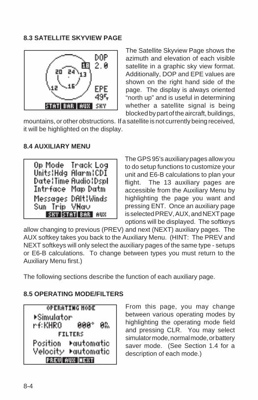
8.3 SATELLITE SKYVIEW PAGE
The Satellite Skyview Page shows theazimuth and elevation of each visiblesatellite in a graphic sky view format.Additionally, DOP and EPE values areshown on the right hand side of thepage. The display is always oriented“north up” and is useful in determiningwhether a satellite signal is beingblocked by part of the aircraft, buildings,
mountains, or other obstructions. If a satellite is not currently being received,it will be highlighted on the display.
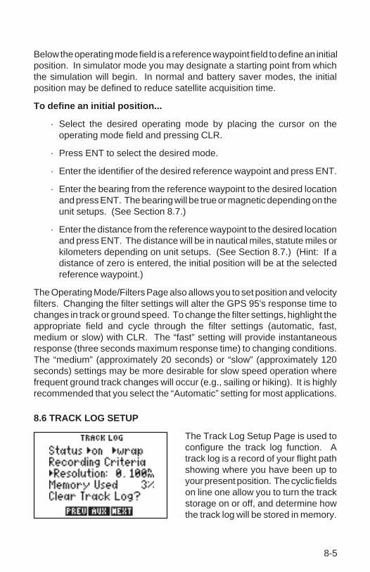
8.4 AUXILIARY MENU
The GPS 95's auxiliary pages allow youto do setup functions to customize yourunit and E6-B calculations to plan yourflight. The 13 auxiliary pages areaccessible from the Auxiliary Menu byhighlighting the page you want andpressing ENT. Once an auxiliary pageis selected PREV, AUX, and NEXT pageoptions will be displayed. The softkeys
allow changing to previous (PREV) and next (NEXT) auxiliary pages. TheAUX softkey takes you back to the Auxiliary Menu. (HINT: The PREV andNEXT softkeys will only select the auxiliary pages of the same type - setupsor E6-B calculations. To change between types you must return to theAuxiliary Menu first.)
The following sections describe the function of each auxiliary page.
8.5 OPERATING MODE/FILTERS
From this page, you may changebetween various operating modes byhighlighting the operating mode fieldand pressing CLR. You may selectsimulator mode, normal mode, or batterysaver mode. (See Section 1.4 for adescription of each mode.)
8-5
Below the operating mode field is a reference waypoint field to define an initialposition. In simulator mode you may designate a starting point from whichthe simulation will begin. In normal and battery saver modes, the initialposition may be defined to reduce satellite acquisition time.
To define an initial position...
· Select the desired operating mode by placing the cursor on theoperating mode field and pressing CLR.
· Press ENT to select the desired mode.
· Enter the identifier of the desired reference waypoint and press ENT.
· Enter the bearing from the reference waypoint to the desired locationand press ENT. The bearing will be true or magnetic depending on theunit setups. (See Section 8.7.)
· Enter the distance from the reference waypoint to the desired locationand press ENT. The distance will be in nautical miles, statute miles orkilometers depending on unit setups. (See Section 8.7.) (Hint: If adistance of zero is entered, the initial position will be at the selectedreference waypoint.)
The Operating Mode/Filters Page also allows you to set position and velocityfilters. Changing the filter settings will alter the GPS 95's response time tochanges in track or ground speed. To change the filter settings, highlight theappropriate field and cycle through the filter settings (automatic, fast,medium or slow) with CLR. The “fast” setting will provide instantaneousresponse (three seconds maximum response time) to changing conditions.The “medium” (approximately 20 seconds) or “slow” (approximately 120seconds) settings may be more desirable for slow speed operation wherefrequent ground track changes will occur (e.g., sailing or hiking). It is highlyrecommended that you select the “Automatic” setting for most applications.
8.6 TRACK LOG SETUP
The Track Log Setup Page is used toconfigure the track log function. Atrack log is a record of your flight pathshowing where you have been up toyour present position. The cyclic fieldson line one allow you to turn the trackstorage on or off, and determine howthe track log will be stored in memory.

8-6
The track storing function may be turned on and off by highlighting the firststatus field and pressing CLR. From the next field, the track may be set to“wrap” around through available memory (deleting the oldest track informationand using the memory to store the new track position), or to “fill” availablememory and then stop. The amount of memory, used at any given moment,is also displayed. When available memory is filled or the track is no longerneeded, it may be cleared by highlighting “Clear Track Log?” and pressingENT. If the “fill” option is selected, a “memory full” message will be displayedwhen all available memory has been used and you must clear the track logto store additional track information.
The ground track is stored at a frequency that you can define either by: Time“Interval”, “Resolution”, or “Distance”. Select the desired frequency unit byhighlighting this field and pressing CLR.
To store the Ground Track at selected time Intervals...
· Highlight the recording criteria field (third line) and select “Interval” withCLR.
· Press ENT.
· Enter the time interval between stored positions starting with hours,then minutes, then seconds. Press ENT after entering data in eachnumeric field.
To store the Ground Track by Distance...
· Highlight the recording criteria field and select “Distance” with CLR.
· Press ENT.
· Enter the distance, and press ENT. When your position moves thisdistance in any direction, a new position is added to the stored groundtrack. NOTE: “Distance” storage may be preferable to “Resolution”storage if the ground track will include a large number of turns.
If the planned course will be primarily straight line travel, you should select“Resolution” storage. In this application, considerably less memory is usedfor the same distance traveled.
To store the Ground Track by Resolution...
· Highlight the recording criteria field and select “Resolution” with CLR.
· Press ENT.

8-7
· Enter the resolution range, and press ENT. When your position movesthis defined range off a projected course line, a new position is addedto the stored ground track.
8.7 UNITS/HEADING SETUP
The Units/Heading Page is used toselect the units to display for position,distance, speed and headinginformation. Select the desired positionunits by highlighting the “POSN” fieldand pressing CLR. You may choosebetween decimal degrees(hddd.ddddd°); degrees and decimal
minutes (hddd°mm.mmm’); degrees, minutes and decimal seconds(hddd°mm’ss.s”); UTM/UPS coordinates; or various other regional grids.
Select the desired distance, speed and altitude units by highlighting the“NAV” field and pressing CLR. You may choose between nautical (nauticalmiles/knots/feet), statute ( miles/miles per hour/feet), or metric (kilometers/kilometers per hour/meters) units. (NOTE: The NAV units setting alsodefines the pressure, temperature and vertical speed units that will be usedfor E6-B calculations.)
Heading information can be displayed referencing magnetic north(automatically calculated or user-defined), referencing true north or referencingcalculated grid headings. Select the desired heading reference by highlightingthe “HDG” field and pressing CLR. When the “Auto Mag Vari[ation]” optionis selected, heading information will reference the automatically calculatedmagnetic variation shown. For most applications, the “Auto Mag” feature willprovide accurate heading information. If the auto-magnetic variation is notcorrect, you may define the magnetic variation by selecting “User Mag Var”.If the “User Mag Var” option is selected, the magnetic variation is thenentered.
To enter a user-defined magnetic variation...
· Highlight the “HDG” field and select “User Mag Var” with CLR.
· Press the right arrow key.
· The variation direction is highlighted. To change the direction, pressCLR.
· Press ENT.
· Enter the variation degrees and press ENT.

8-8
8.8 ALARMS/CDI SETUP
From the Alarms/CDI Page, you maydefine three alarms (and turn them onor off) and configure the graphic CDI toyour preference. Alarms are availablefor course deviation, arrival at adestination waypoint, and an alarmclock.
The CDI alarm will notify you with an alarm tone and the message “CDIAlarm” if you have deviated off course beyond the limit that you set. (This canbe useful while flying in an airway or navigating a narrow channel.)
To set the CDI alarm...
· Highlight the CDI alarm distance field.
· Enter the maximum allowable course deviation distance.
· Press ENT.
· The on/off cyclic field is highlighted. If the alarm is not turned on, pressCLR.
The arrival alarm will inform you with an alarm tone and the message “Arrivalat ____” (where the blank is filled in with a waypoint identifier) when you reachyour destination. The alarm distance will also be used to inform you whenyou approach a route waypoint with the message “Approaching ____”(again, with the blank filled in by a waypoint name).
To set the arrival alarm ...
· Highlight the arrival alarm distance and enter the distance from adestination at which you want the alarm to sound.
· Press ENT.
· The on/off cyclic field is highlighted. If the alarm is not turned on, pressCLR.
The GPS 95 also features an alarm clock which can provide an alarm toneand the message “Alarm Clock” at a time that you specify.

8-9
To set the alarm clock...
· Highlight the alarm clock time and enter the desired alarm time. NOTE:The alarm time may be either UTC or local time depending on thesetting on the Date/Time Page. (See Section 8.9.)
· Press ENT.
· The on/off cyclic field is highlighted. If the alarm is not turned on, pressCLR.
The graphic CDI may be configured to the desired scale and steeringorientation. Scale settings of ±.25, 1.25, or 5.00 units (nautical miles, statutemiles, or kilometers) are available. The scale setting represents the distancefrom center of the CDI to either end.
To set the CDI scale...
· Highlight the CDI scale field.
· Press CLR to select the desired scale.
The CDI “Steer To” orientation determines how you interpret the “D-Bar”when it moves. You may select a “Steer to >Center” or “Steer to >D-Bar”orientation. A “Steer to Center” orientation, in effect, displays your positionas the “D-Bar” and the center of CDI is the desired track. Thus, when youare off course, you would steer towards the center of the scale. A “Steer toD-Bar” orientation is just the opposite. The “D-Bar” represents the desiredtrack and the center of the scale represents your position. When you are offcourse, you then steer towards the “D-Bar”. A “Steer to D-Bar” orientationis the typical setting for aviation use and will make the GPS 95's graphic CDIrespond much like the CDI on your instrument panel.
To set the CDI orientation...
· Highlight the “steer to” field.
· Press CLR to select the desired orientation.

8-10
8.9 DATE/TIME
The Date/Time Page displays the UTC(Coordinated Universal Time,Greenwich Mean Time or Zulu Time)date and time. The local offset or timedifference is shown on the next line.For time zones west of the UTC zone,enter a negative offset. (HINT: Theminus sign is on the “9” key.) AppendixE contains a list of time offsets.
The cyclic field for “Display” options determines which time, UTC or Local,will be displayed on all other GPS 95 pages.
To display UTC or local time...
· Highlight the time display field.
· Press CLR to select the desired time reference.
The timer field can be selected as “Count Up” or “Count Down” by highlightingand pressing CLR. This timer is useful for measuring the elapsed time sincea certain event, or it can tell you when a specified amount of time has expired.
To set the count up timer...
· Place the cursor on the timer option field.
· Press CLR to select “count up”.
· Press the right arrow key.
· Press CLR and ENT to clear the hours field.
· Press CLR and ENT to clear the minutes field.
· Press CLR and ENT to clear the seconds field. The count up timer willbegin counting the elapsed time.

8-11
To set the count down timer...
· Place the cursor on the timer option field.
· Press CLR to select “count down”.
· Press the right arrow key.
· Enter the number of hours to count down from and press ENT.
· Enter the number of minutes to count down from and press ENT.
· Enter the number of seconds to count down from and press ENT. Thecount down timer will begin counting down from the selected time.
8.10 AUDIO AND DISPLAY SETUP
From the Audio/Display Page you canturn the message and/or keypad toneson and off, change the display contrastand change the time-out for the displaybacklighting.
The tone option allows you to turn theGPS 95's audio tone on or off asdesired. You may turn the keypad
feedback tone off, but leave the message tone on; have both tones on; orhave both tones off.
To turn audio tones on/off...
· Highlight the tone option field.
· Press CLR to select the desired option.
You may also adjust the contrast of the GPS 95 display to your preferences.
To change the display contrast...
· Highlight “Change Contrast?” and press ENT.
· The contrast bar is highlighted. Press the left or right arrow key tochange the contrast level.
· When the desired contrast level is reached, press ENT.
The backlighting time-out determines the length of time the display andkeypad backlighting will remain on. If no keys are pressed for the specifiedtime, the backlighting will automatically shut off to conserve battery power.

8-12
To set the backlighting time-out...
· Highlight the backlighting time-out field.
· Enter the desired time for backlighting to remain on. If you wish to havethe backlighting on at all times, enter zero.
· Press ENT.
8.11 INTERFACE SETUP
From the Interface Page, you mayselect the input and/or output formatneeded to connect your GPS 95 toother equipment: PC, NMEA device,etc. You may select no input/output(NONE/NONE), GARMIN input/output(GARMIN/GARMIN), NMEA output(NONE/NMEA), RTCM input/NMEAoutput (RTCM/NMEA) or RTCM input(RTCM/NONE).
When the NMEA output is selected a second cyclic field appears. From thissecond field you may select the desired NMEA format: NMEA 0180, NMEA0182, or NMEA 0183.
To select a NMEA output...
· Place the cursor on the input/output format field.
· Press CLR until the desired NMEA output option (NONE/NMEA orRTCM/NMEA) is displayed.
· Press the right arrow key.
· Select the desired NMEA format by pressing CLR.
A second cyclic field also appearswhen the GARMIN input/output isselected. The GARMIN option allowsyou to exchange data such aswaypoints, routes, track logs andsatellite almanac data with anotherGPS 95 or with a PC-compatiblecomputer. You may select between
acting as a host to data exchanges (Host), requesting data (Req) or sendingdata (Send). During the data transfer process the number of data packetsbeing exchanged will be displayed.

8-13
To select GARMIN input/output...
· Place the cursor on the input/output format field.
· Press CLR until the GARMIN input/output option is selected.
· Press the right arrow key.
· Select “Host”, “Req[uest]”, or “Send” by pressing CLR. (NOTE: Youshould select the “Host” option when using the GPS 95 with a PC.When exchanging data between two GPS 95s, one should be set to“Host” and the second should be set to the desired data transfer option- “Req[uest]” or “Send”.)
The GPS 95 can use Differential GPS(DGPS) corrections in RTCM SC-104version 2.0 format. DGPS correctionsin this format can be received from anexternal device (capable of output in 6to 8 byte format as specified by RTCMSC-104 version 2.0) by connecting thedevice to the input port on the back of
the GPS 95 and selecting an RTCM input interface mode. Two RTCM inputmodes are available; one which allows no output and another which allowsNMEA output in 0180, 0182, or 0183 format.
To select an RTCM input...
· Place the cursor on the input format field.
· Press CLR until the desired RTCM input option (RTCM/NONE orRTCM/NMEA) is displayed.
· Press the right arrow key.
· If RTCM/NONE is selected: Press CLR to select the appropriate baudrate.
· If RTCM/NMEA is selected: Press CLR to select the desired NMEAoutput format. (NOTE: With RTCM/NMEA selected the RTCM baudrate is automatically set to 1200 or 4800.)
If the RTCM input is selected, but the GPS 95 is not connected to an RTCMdevice, the unit will alert you with the message “No RTCM Input”. If the GPS95 does not receive sufficient data to compute a DGPS-corrected position,the message “No DGPS Position” will appear.

8-14
8.12 MAP DATUM SELECTION
Select the desired map datumreference from the Map Datum Page.You may choose from 102 pre-definedmap datums, or you may define yourown. If the sectional/chart you areusing specifies a reference datum,select that datum on your GPS 95. Ifthe sectional/chart does not specify a
reference datum, you may select each datum applicable to your region untilyou find the datum that provides the best positioning at a known point. NOTE:The GPS 95 is shipped from the factory with the WGS 84 datum selected.
To change the pre-defined datum...
· Highlight the “Change?” field and press ENT.
· With the arrow keys, find the desired datum and highlight it.
· Press ENT. The new datum is selected.
The user-defined datum option allowsyou to custom-tailor a datum referencefrom which all position coordinates arecalculated. All entries are defined asdifferences from the WGS 84 standarddatum. (CAUTION: Selection anduse of the user datum function is forindividuals experienced in the use ofmap datums. If the pre-defined map
datums do not correspond to the chart you are using and you are unsure ofthe correct entries required to correspond to that chart, contact the chartmanufacturer. Incorrect entries for a user-defined datum may result insubstantial position errors.)
To define a user datum...
· Place the cursor over the cyclic field on line one.
· Press CLR to select “User-defined”.
· Enter the 5 parameters of the user map datum. The sign of theparameters should follow the convention: WGS 84 - local geodeticsystem.

8-15
8.13 MESSAGES
You may recall from Section 2.6 thatsome messages will remain on theMessage Page after being viewed.When this occurs, the “MSG”annunciator remains on (but does notflash) in the lower left corner. To viewthese messages, select “Messages”from the Auxiliary Page. (SeeAppendix A for a description ofavailable messages.)
8.14 DENSITY ALTITUDE/TRUE AIRSPEED/WINDS ALOFT
The GPS 95 provides density altitude,true airspeed (TAS) and winds aloftcalculators for your convenience. Thedensity altitude and TAS calculationswill help you determine critical aircraftperformance data.
To calculate density altitude and true airspeed...
· Place the cursor on the indicated altitude (IAlt) field.
· Enter the indicated altitude from your altimeter and press ENT.
· Enter your calibrated airspeed (CAS) and press ENT. If you do notknow your calibrated airspeed, use indicated airspeed instead.
· Enter your current altimeter setting and press ENT.
· Enter the total air temperature (TAT). The GPS 95 will display theresulting density altitude and true airspeed. (NOTE: TAT is thetemperature of the air including the heating effect caused by speed.The temperature read on a standard outside air temperature gaugefound in most piston aircraft is TAT.)
The winds aloft calculation determines the direction (true) and speed of thewind. This calculation requires TAS and heading information. If you havealready calculated density altitude and TAS, the TAS value will be used forthe winds aloft calculation; otherwise you may enter the correct TAS value.

8-16
To calculate winds aloft...
· If you have not already calculated TAS: place the cursor over the TASfield, enter the correct true airspeed and press ENT.
· Place the cursor over the heading (Hdg) field.
· Enter the current heading (magnetic) from your heading indicator andpress ENT. The GPS 95 will display the wind direction, speed, and thehead/tail wind you are encountering.
8.15 SUNRISE/SUNSET PLANNING
The Sunrise/Sunset Page allows youto calculate the sunrise and sunsettimes for a given waypoint location ona selected date (from the year 1990through 2089).
To calculate the sunrise/sunset times for a waypoint...
· Highlight the waypoint name field and enter the desired waypointname.
· Press ENT.
· The date field is highlighted. Enter the day, then month, then year tocalculate the sunrise/sunset times for. Press ENT on eachalphanumeric/numeric field.
· Once the year is selected and ENT is pressed, the calculated sunriseand sunset times will be shown. Please note that the times shown willbe either UTC or local depending on the selection made on the Date/Time Page. (See Section 8.9.)

8-17
8.16 TRIP AND FUEL PLANNING
The Trip and Fuel Planning Page allowsyou to calculate time and fuelrequirements between any twowaypoints or for any programmedroute. On the first cyclic field, you willchoose between waypoint (WPT) orroute (RTE) planning by highlightingand pressing CLR. If route planning is
selected, you would then select the desired route number and the portion ofthe route (a given leg or all of the route) to calculate for.
The final step is to enter speed and fuel flow rates. The GPS 95 will thencalculate the desired track (DTK), fuel requirements (REQ), distance (DIS),and estimated time enroute (ETE).
To perform a trip and fuel plan, waypoint to waypoint...
· Highlight the first cyclic field (topleft), and press CLR to select“WPTS:”.
· Highlight the waypoint name field(second line), and enter the firstwaypoint name followed by ENT.
· The second waypoint name field isnow highlighted. Enter the secondwaypoint name followed by ENT.
· The speed (SPD) field is highlighted. Enter the planned speed, andpress ENT.
· The fuel flow (Flow) field is highlighted. Enter the estimated fuel flowfollowed by ENT.
· The GPS 95 will now display the calculated figures.

8-18
To perform a trip and fuel plan for a route...
· Highlight the first cyclic field (topleft) and select “RTE” with CLR.
· Highlight the next cyclic field andselect the desired route number bypressing CLR.
· Highlight the “Leg>” field and selectthe desired leg, or select “All” for theentire route, using CLR.
· Highlight the “SPD:” field and enter the planned speed, followed byENT.
· Highlight the “Flow:” field and enter the estimated fuel flow followed byENT.
· The GPS 95 will now display the calculated figures.
NOTE: When “all” is selected, no desired track (DTK) will be shown sincethis value only applies to an individual leg.
8.17 VERTICAL NAVIGATION PLANNING

8-19
Pilots will find the GPS 95's verticalnavigation (VNAV) function useful forcalculating vertical speedrequirements. In order to use theVNAV feature, aircraft ground speedmust be greater than 35 knots.
To calculate vertical speed requirements...
· Place the cursor on the initial (Frm) altitude field.
· Enter the initial altitude and press ENT.
· Enter the final (To) altitude and press ENT.
· Enter the offset distance, from the desired waypoint, at which you willreach your final altitude. Press ENT.
· Select “Before” if the offset is before the waypoint, or “After” if the offsetis beyond the waypoint, by pressing CLR.
· If an active route is being used: press CLR to select the route waypointto which the offset applies.
· You now have defined how far before, or after, the indicated waypointyou wish to be at the final altitude. The GPS 95 will display the requiredvertical speed.
To activate the VNAV function...
· Review the calculated vertical speed. If you wish to change the verticalspeed: place the cursor on the vertical speed (At) field, enter thedesired vertical speed and press ENT.
· Place the cursor over the “VN” field.
· Press CLR to turn the VNAV function on. The VNAV status on thebottom line will change from “Enter VNAV Profile” to “Begin at _____”(with the blank indicating how long before the maneuver should begin),or “Navigating” if the VNAV maneuver is already in progress. You willbe informed with the message “Start Altitude Change” when you areless than 15 seconds from the point at which the VNAV maneuver isto begin.

8-20
When VNAV is active, this page will recommend the altitude and verticalspeed required to complete the maneuver. Remember that these are onlyrecommendations. You will be informed with the message “Final AltitudeAlert” when the recommended altitude is within 1000 feet of the final altitude.The VNAV function will be cancelled automatically if the active route (orGOTO) is changed in any way (e.g., setting a new GOTO destination oradding a waypoint to a route). You will be informed with the message “VNAVCancelled” if this occurs. If the aircraft ground speed does not exceed 35knots, or a route waypoint that has already been passed is selected, the GPS95 will display an “Invalid profile” status on the bottom line. The GPS 95 willdisplay “No Active Waypoint” on the bottom line if no route, or GOTOdestination, has been activated.
WARNING: Altitude and climb rate should be controlled only by the pilot incommand with due regard for airspeed and other aircraft performancelimitations.

9-1
CHAPTER 9
SAMPLE TRIP USING ROUTES
Now that you have gained a basic understanding for your GPS 95, you areready to explore the route capabilities of this unit. The sample illustrationsin this chapter assume that the factory default settings have not beenchanged. If you have changed these parameters the unit may display slightlydifferent data than presented here.
You are planning a trip from St. Petersburg, Florida to the Dry Tortugas andthen on to Key West, Florida . Turn on the GPS 95 to begin this sample trip.
Dry Tortugas(DRYTG)
St. Petersburg(KPIE)
Key West(KEYW)

9-2
The welcome screen is displayed andthe GPS 95 performs several self tests.
After about five seconds the SatelliteBar Graph Page is displayed and theGPS 95 will begin acquiring satellites.
Since this is a simulated trip you do notneed to wait for the GPS 95 to acquire satellites. You will set the operatingmode to “simulator” and define the starting location (St. Petersburg).
Setting the simulator mode and initial position...
Select the Auxiliary Menu by pressingthe AUX softkey (the “1” key in thiscase).
Press the right arrow key to place thecursor over “op mode” and press ENT.
The Operating Mode Page is displayed
ABC1
ENT

9-3
*Press repeatedly until
“Simulator” is displayed
*Continue pressing the
alphanumeric and arrow
keys, if needed, to enter
the waypoint identifier
CLR
ENT
JKL4
PQR6
showing the current operational mode.
Press the right arrow to place the cursoron the operational mode field.
Press CLR (repeatedly) until“Simulator?” is displayed.
Press ENT to select simulator mode.
The cursor is on the reference identifierfield. Set the initial position by enteringthe identifier for St. Petersburg, Florida(KPIE).
Press the “4” key to select the letter“K”.
Press the “6” key followed by the leftarrow key to select the letter “P”.
Continue pressing the alphanumericand, if needed, arrow keys until thewaypoint identifier has been entered.Press ENT when complete.
The Waypoint Definition Page is
ENT

9-4
ENT
CLR
STU7
ENT
*Continue pressing the
alphanumeric keys to
enter the latitude minutesENT
*If needed to select
proper hemisphere
displayed indicating that the positioncoordinates for St. Petersburg, Florida(KPIE) are not known.
Enter the latitude for KPIE (N27°54.646'). Begin by selecting the properhemisphere. If “N” for north is notdisplayed, press CLR.
Press ENT when the properhemisphere is selected.
Enter the latitude degrees. Press the“2” key and the “7” key. Press ENTwhen complete.
Enter the latitude minutes. Begin bypressing the “5” key.
Continue pressing the alphanumerickeys until the latitude minutes havebeen entered. Press ENT whencomplete.
Enter the longitude of KPIE (W82°
DEF2
MNO5

9-5
41.244') in the same manner as wasused for the latitude. Press ENT oncedata is entered into each field.
Press the right arrow key twice toplace the cursor on “USE?” and pressENT.
Since the trip will begin at St.Petersburg, there is no need to definea reference bearing from this waypoint.Press ENT.
Enter a distance of zero and pressENT.
ENT
*Enter the longitude using
the same steps shown
above
0
ENT
ENT
ENT

9-6
Before you begin the trip, all waypoints used along the route must be inmemory. The location for St. Petersburg was just created when the initialposition was set. The position coordinates for the Dry Tortugas (DRYTG)and Key West (KEYW) must still be entered. Below are the identifiers andlocations for waypoints used in this sample trip:
Creating the “DRYTG” and “KEYW” waypoints...
Press WPT and the WPT softkey, ifneeded, to select the WaypointDefinition Page.
Press the right arrow key to place thecursor on the waypoint identifier field.
Enter the waypoint identifier, DRYTG,using the alphanumeric and arrowkeys. Begin by pressing the “2” key,followed by the left arrow, to select theletter “D”.
Press the “6” key, followed by the rightarrow, to select the letter “R”.
Continue pressing the alphanumericand, if needed, arrow keys until thewaypoint identifier has been entered.Press ENT when complete.
WPT*Plus WPT softkey, if
needed
DEF2
PQR6
ENT
*Continue pressing the
alphanumeric and
arrow keys, if needed,
to select waypoint
identifier
Indent Latitude Longitude
KPIE N27°54.646' W082°41.244'
DRYTG N24°38.430' W083°08.301'
KEYW N24°33.370' W081°45.574'

9-7
Enter the latitude of DRYTG(N24°38.430'). Begin by selecting theproper hemisphere, If “N” for north isnot displayed, press CLR.
Press ENT when the properhemisphere is selected.
Enter the latitude degrees. Press the“2” key and the “4” key. Press ENTwhen complete.
Enter the latitude minutes. Begin bypressing the “3” key.
Continue pressing the alphanumerickeys until the latitude minutes havebeen entered. Press ENT whencomplete.
CLR
ENT
ENT
GHI3
ENT
JKL4
*Continue pressing the
alphanumeric keys to
enter the latitude
minutes
*If needed to select
proper hemisphere
DEF2

9-8
Enter the longitude of DRYTG(W083°08.301') in the same manneras was used for the latitude. PressENT once data is entered into eachfield. (NOTE: You do not need toenter the leading zero for degrees orminutes. In both cases you may beginby pressing the “8” key.)
Press the right arrow key three timesto place the cursor on the waypointidentifier field.
Enter the Key West (KEYW) waypointand its coordinates (N24° 33.370' W81°45.574') using the same steps used tocreate DRYTG. Press ENT after datais entered into each field.
This trip will take you to an intermediate destination (Dry Tortugas) and thena final destination (Key West). You could go to each destination using theGOTO function as described in Chapter 4. (Select GOTO DRYTG, then,upon reaching DRYTG, select GOTO KEYW.) However, for this sample trip,the route capabilities of the GPS 95 will be utilized.
ENT
*Enter the longitude
using the same steps
shown above
ENT *Enter KEYW waypoint
using same steps as
above for DRYTG

9-9
RTE*Plus RTE softkey, if
needed
CLR
JKL4
PQR6
To create the sample route...
Press RTE and the RTE softkey, ifneeded, to select the Route DefinitionPage.
Press the right arrow to place thecursor on the route number field.
Press CLR to select route 1. Noticethat the route is empty; it does notcontain any waypoints. (If route 1 isnot empty, select a different route.)
Press the right arrow key twice toplace the cursor on the first waypointidentifier field.
Enter the identifier for St. Petersburg(KPIE). Begin by pressing the “4” keyto select the letter “K”.
Press the “6” key, followed by the leftarrow key, to select the letter “P”.

9-10
Continue pressing the alphanumericand, if needed, arrow keys until thewaypoint identifier is added to the route.Press ENT when complete. The cursoris on the second waypoint identifierfield.
Enter the identifier for the Dry Tortugas(DRYTG) using the alphanumeric andarrow keys. Press ENT whencomplete. The cursor is now on thethird waypoint identifier field.
Enter the identifier for Key West(KEYW) using the alphanumeric andarrow keys. Press ENT whencomplete. The Route Definition Pageshould now appear as illustrated.
As you see, you have just created a route that will take you from St.Petersburg, over the Dry Tortugas and on to Key West. Once activated, theGPS 95 will calculate navigation data based on the route.
*Continue pressing the
alphanumeric and
arrow keys, if needed,
to enter the waypoint
identifier
ENT
*Enter the next
waypoint identifier
using the alphanumeric
keys
ENT
*Enter the next
waypoint identifier
using the alphanumeric
keys
ENT
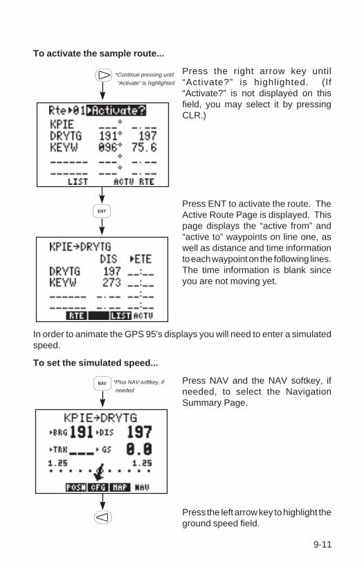
9-11
*Continue pressing until
“Activate” is highlighted
ENT
To activate the sample route...
Press the right arrow key until“Activate?” is highlighted. (If“Activate?” is not displayed on thisfield, you may select it by pressingCLR.)
Press ENT to activate the route. TheActive Route Page is displayed. Thispage displays the “active from” and“active to” waypoints on line one, aswell as distance and time informationto each waypoint on the following lines.The time information is blank sinceyou are not moving yet.
In order to animate the GPS 95's displays you will need to enter a simulatedspeed.
To set the simulated speed...
Press NAV and the NAV softkey, ifneeded, to select the NavigationSummary Page.
Press the left arrow key to highlight theground speed field.
NAV *Plus NAV softkey, if
needed
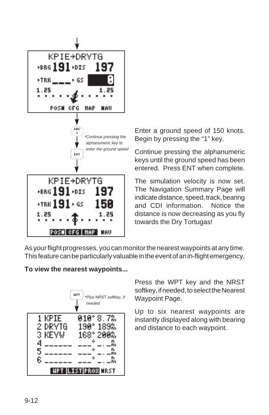
9-12
Enter a ground speed of 150 knots.Begin by pressing the “1” key.
Continue pressing the alphanumerickeys until the ground speed has beenentered. Press ENT when complete.
The simulation velocity is now set.The Navigation Summary Page willindicate distance, speed, track, bearingand CDI information. Notice thedistance is now decreasing as you flytowards the Dry Tortugas!
As your flight progresses, you can monitor the nearest waypoints at any time.This feature can be particularly valuable in the event of an in-flight emergency.
To view the nearest waypoints...
Press the WPT key and the NRSTsoftkey, if needed, to select the NearestWaypoint Page.
Up to six nearest waypoints areinstantly displayed along with bearingand distance to each waypoint.
*Continue pressing the
alphanumeric key to
enter the ground speed
ABC1
ENT
WPT*Plus NRST softkey, if
needed

9-13
In an actual emergency you could instantly plot a course to a nearestwaypoint by highlighting the desired waypoint (using the arrow keys),pressing GOTO and ENT. The GPS 95 would override the route and providenavigation information to direct you to the selected waypoint.
Experiment with your GPS 95!
· Now that you have started on a trip to the Dry Tortugas, why don't youtake some time to experiment with the GPS 95? Press each functionkey to get familiar with the available pages. Examine the Active RoutePage and the Navigation Summary Page as the simulation progresses.If you want, change the simulation speed. You won't break the GPS95 even if you enter a speed of 999 knots.
· As you progress through the simulation, the GPS 95 will alert you witha message when you are within one minute of reaching the DryTortugas. When passing DRYTG, the GPS 95 will automaticallysequence to the next waypoint, KEYW.
· At some point during the simulation you may wish to try the GOTOfunction. Suppose severe weather was reported in the Dry Tortugasarea. You wish to shorten your trip by heading directly to Key West.Simply press the GOTO key and enter KEYW. The GPS 95 will set aninstantaneous course and you are on your way to Key West.
· If you have not customized your unit, this may be a good time to reviewChapter 8 for information concerning custom settings. Doing so willhelp you understand what each setting will do.
· If you wish to stop the simulation, simply turn the GPS 95 off. Werecommend that you delete the route and waypoint created in thissimulation prior to using your unit again. (See Section 3.3 forinformation on deleting waypoints and Section 6.5 for information ondeleting routes.)

A-1
APPENDIX A
MESSAGES
The GPS 95 uses the Message Page to communicate important informationto you. Some messages are advisory in nature, others are warnings that mayrequire your intervention. This appendix provides a complete list of messagesand their meanings. Please pay careful attention to all messages.
Alarm Clock - The alarm time for the alarm clock has been reached.
Approaching ____ - You are less than one minute from reaching theindicated waypoint.
Arrival at ____ - Your craft has entered the arrival alarm circle for theindicated destination waypoint.
Battery Low - The battery pack is low on power. AA batteries should bereplaced or the rechargeable battery pack should be recharged for continuedoperation.
Can't Chng Activ WPT - An attempt has been made to modify the positionof the “active to” or “active from” waypoint. The GPS 95 will not allow themodifications.
CDI Alarm - Your course deviation has exceeded the limit that you specifiedon the Alarms/CDI Page.
Degraded Accuracy - The accuracy of the GPS 95 position is degradedbeyond 500 meters due to satellite geometry or data quality. Additional crosschecking should be performed by the user to verify the integrity of the GPSposition.
Final altitude alert - The suggested VNAV altitude is within 1000 feet of thefinal altitude entered on the VNAV Page.
Leg Not Smoothed - The upcoming leg is too short for smooth waypointtransitions. Expect a rapid change in the CDI.
Memory Battery Low - The battery that sustains user memory is low andshould be replaced by an authorized GARMIN service center as soon aspossible. Failure to do so may result in loss of stored data, including allwaypoints and routes.

A-2
Need Altitude - The GPS 95 needs altitude to start and/or continue 2Dnavigation. Press NAV and enter your current altitude. The altitude you entershould be as accurate as possible. An inaccurate altitude will result in aninaccurate position and navigation information.
No DGPS Position - An RTCM input has been selected, but not enoughDGPS data is available to calculate a corrected position.
No RTCM Input - An RTCM input has been selected, but no data is beingreceived or the input data is in the wrong format.
Osc Needs Adjustment - The GPS 95 has detected excessive drift in itsinternal crystal oscillator which may result in longer acquisition time. The unitshould be taken to an authorized GARMIN service center as soon aspossible.
Poor GPS Coverage - The GPS 95 cannot acquire sufficient satellitesnecessary to provide navigation.
Pwr Down and Re-init - The GPS 95 is unable to compute a position dueto abnormal satellite conditions. Power down the unit and verify that theposition on the Position Page is within a few degrees of your actual position.
Prox Alarm ____ - Your craft has penetrated the alarm circle of a proximitywaypoint.
Proximity List Full - An attempt has been made to add more than ninewaypoints to the proximity list. The GPS 95 will not allow more than nineproximity waypoints.
Proximity Overlap - The circles defined by two proximity waypoints overlay.When entering the area of the overlap, the GPS 95 will alert you of the closestproximity waypoint, but not both. You should be certain this condition isdesirable.
Proximity Waypoint - An attempt has been made to delete a waypoint forwhich a proximity alarm has been defined. You must remove the waypointfrom the proximity list before the waypoint can be deleted.
Received Invalid Wpt - A waypoint was received in an upload/transferoperation that has an invalid identifier or position.
Receiver Failed - The GPS 95 has detected a failure in the receiverhardware. If the message persists, the GPS 95 is unusable and should betaken to an authorized GARMIN service center.

A-3
ROM Failed - The GPS 95 has detected a failure in its permanent memory.If this message occurs, the unit is unusable and should be taken to anauthorized GARMIN service center.
Route is Full - An attempt has been made to add more than 30 waypointsto a route. The GPS 95 will not allow more than 30 waypoints per route.
Route Not Empty - An attempt has been made to copy a route to a non-empty route. The GPS 95 will not allow you to copy a route to a non-emptyroute.
Route Waypoint - An attempt has been made to delete a waypoint which isa member of one or more routes. You must remove the waypoint from allroutes before the waypoint can be deleted.
RTCM Input Failed - The GPS 95 was receiving RTCM inputs, but the datasignal has been interrupted.
Searching the Sky - The GPS 95 is in the search-the-sky mode. Allow theunit to complete its data collection before turning it off. This process takesapproximately 15 minutes.
Start altitude chng - The altitude change entered on the VNAV Page isabout to begin.
Steep Turn Ahead - This message appears approximately one minute priorto a turn that requires a bank angle in excess of 25 degrees in order to stayon course.
Stored Data Lost - Stored user data, including waypoints, routes, andsatellite orbital data has been lost due to a low memory battery.
Timer Expired - The count down timer has expired.
Track Memory Full - The track memory is full. Go to the Track Log SetupPage to clear the memory.
Transfer Completed - Data transfer operations are complete.
VNAV cancelled - The VNAV function has been cancelled due to a changein the active route.
WPT Exists ____ - You have entered a waypoint name on the AutoStoreTM
Page that already exists in memory. Enter a waypoint name that does notexist.
WPT Memory Full - The waypoint memory is full. You should delete unusedwaypoints to make room for new waypoints.

B-1
APPENDIX B
GLOSSARY AND NAVIGATION TERMS
B.1 DEFINITIONS
This section provides an illustration of and definitions for the terms used inthis manual.

B-2
Velocity/time terms:
GS Ground speed. GS is the speed measured relative to a groundposition; also known as velocity over ground (VOG).
ETA Estimated time of arrival. ETA is the estimated time you will reachthe “active to” waypoint based on current GS. This time is selectableas either UTC or local.
ETE Estimated time enroute. ETE is the time it will take to reach the“active to” waypoint based on current GS.
Direction terms:
DTK Desired track. DTK is the course between the “from” and “to”waypoints. In the case of the GOTO function, the “from” waypointis the location at which the GOTO function was activated.
BRG Bearing. BRG is the direction from your present position to the“active to” waypoint.
CTS Course to steer. CTS is the recommended direction to steer in orderto reduce cross track error and stay on course. (See Section B.2 foran example using CTS.)
TRK Track. TRK is the direction of movement relative to a groundposition.
TRN Turn angle. TRN is the difference between BRG and TRK. “L”indicates you should turn to the left, “R” indicate you should turn tothe right. The degrees indicate the angle you are off course.
Distance terms :
DIS Distance. DIS is the great circle distance from your position to the“active to” waypoint.
XTK Crosstrack. XTK is the cross track error, or distance that you are offcourse. If the crosstrack error exceeds the CDI scale setting, theXTK distance will also be displayed on the appropriate side of theCDI.
V VNAV altitude. V is the recommended altitude at which you shouldbe in order to accomplish a VNAV maneuver. This information isonly available when the VNAV function has been activated.

B-3
Satellite terms:
DOP Dilution of precision. DOP is a measure of the satellite geometryquality and hence the relative accuracy of your position (onemeaning the best and ten meaning poor).
EPE Estimated position error. EPE, which is computed using the satellitegeometry (DOP), signal and data quality, receiver tracking statusand other factors, is an overall measure of your position accuracy.
B.2 COURSE TO STEER (CTS)
Course To Steer is a GARMIN exclusive that recommends an optimaldirection to steer that will guide you to the course and proceed efficientlyalong your route.

B-4
As an example, suppose you activate the route illustrated above. The GPS95 chooses the closest leg with a desired track of 45 degrees but yourposition happens to be two nautical miles off course. The unit will automaticallycompute the optimal course to steer (which is due north in this example).Press the NAV key until the Nav Summary Page is displayed, then select“CTS” on the first cyclic field. Using the CTS direction (000°), turn so that thetrack (TRK) and CTS direction match.
As you approach the course, CTS will slowly change and, once on course,will be identical to the desired track.

C-1
APPENDIX C
INSTALLATION AND MAINTENANCE
C.1 SPECIFICATIONS
GPS 95 SPECIFICATIONS*
—————————————————————————————-
PHYSICAL
Case: Waterproof
Size: Portable: 3.23"w x 6.26"h x 1.46"d(82mm x 159mm x 37mm)
Fixed: 3.23"w x 4.87"h x 1.46"d(82mm x 124mm x 37mm)
Weight: 14 ounces (0.4 kg) without battery pack 19ounces (0.54 kg) with battery pack
POWER
Input Alkaline battery pack (4 AA size)Rechargeable battery pack (Optional)12 or 24 volt DC with power cable (5-40 VDC)115 or 230 volt AC with AC Adapter
Consumption 1.6 watts in Normal mode (without backlighting)
ENVIRONMENTAL
Temperature: -15°C to +70°C (+5°F to +158°F ) operating-40°C to +70°C (-40°F to +158°F) storage
Humidity: 95% non-condensing
PERFORMANCE
Receiver: MultiTracTM, tracking up to 8 satellites
Frequency: L1, 1.57542 GHz
Acquisition Time: 2 minutes 2D(typical) 2.5 minutes 3D
15 seconds Warm Start (with ephemeris)

C-2
Update Rate: Once per second, continuously
Accuracy: Position: 15 meters (49 ft) RMS**
Velocity: 0.1 knots RMS steady state
Dynamics: 999 knots velocity, 3g dynamics
INTERFACES
NMEA 0180
NMEA 0182
NMEA 0183 (Version 1.5; December 1987)
Approved sentences:
GPBWC, GPGLL, GPRMB, GPRMC, GPR00, GPWPL, GPXTE
Proprietary sentences:
PGRMZ
Transmission rate:
GPBWC, GPGLL, GPRMB, GPRMC, GPXTE, and PGRMZtransmitted once every two seconds.
GPR00 transmitted once every (# of all waypoints + 1) * 2seconds. For example, if there are two route waypoints, thissentence will be transmitted once every six seconds.
GPWPL transmits all route waypoints in (# of route waypoints + 1)* 2 seconds. For example, if there are two route waypoints, thissentence will be transmitted twice every six seconds.
—————————————————————————————-
NOTES:
* All specifications are subject to change without notice.** Subject to accuracy degradation to 100m 2DRMS under the United
States Department of Defense imposed Selective Availability program.(Due to satellite geometry, altitude error is typically two to three timesthe horizontal position error.)

C-3
C.2 ELECTRICAL WIRING
The GPS 95 power/data cable allows you to connect the unit to vehicle powersystems, other electronics, and a remote alarm/beeper. The power/datacable has a 7-pin intermediate connector to facilitate quick disconnection ofall electrical connections and easy removal of the entire yoke mount from theaircraft. The GPS 95 is supplied with two wire harnesses: one with a cigarettelighter plug for temporary use and the other for permanent wiring. The figuresbelow illustrate the two wiring options.
OR
To connect to vehicle power systems...
· Connect the RED harness lead (with fuse) to the positive (+) side of a5-40 volt DC power source.
· Connect the BLACK harness lead to the negative (-) side of the 5-40volt DC power source.
The GPS 95 will drive a remote alarm or relay that requires no more than 100milliamps of current. (WARNING: Devices which draw current in excess of100 milliamperes may damage your unit and will void your warranty. Consultthe instructions included with the remote alarm or relay for current draininformation.)

C-4
To connect to a remote alarm system...
· Connect the BLUE harness lead to the negative side of a transistoralarm or relay switch.
· Connect the positive side of the alarm or relay to the positive side ofthe 5-40 volt DC power source.
The GPS 95 may be connected to a PC-compatible computer using a NMEA0183 data interface or to marine electronics such as an autopilot or plotterwhich use an NMEA 0180, NMEA 0182 or NMEA 0183 data interface. The unitcan provide data for up to three NMEA “listeners” simultaneously. Refer toinstallation instructions of these devices for further information.
To connect the GPS 95 to an NMEA electronic device...
· Connect the BROWN harness lead to the NMEA “A” line of a two-wire,shielded cable.
· Connect the BLACK harness lead to the NMEA “B” line of the shieldedcable.
· Connect the BLACK harness lead to the shield of the shielded cable.(The opposite end of the shield should not be grounded.)
C.3 YOKE MOUNT INSTALLATION
The GPS 95 is equipped with a yoke mount which can quickly be attachedto the control yoke for easy access and visibility without blocking the view ofthe instrument panel. The yoke mount can quickly be detached and stowedin the carrying bag along with the GPS 95 radio and any other accessoriesyou might wish to take with you. The clamp that comes with the standardyoke mount will fit the control yoke of more than 90% of general aviationaircraft. If the standard clamp will not fit your aircraft, call our toll-free productsupport number to exchange for the proper type of clamp for your aircraft.Generally, the standard clamp will not fit the following: Bonanza/Baron,Commanche, large Piper twins, and some other large Beech models.
The GPS 95 can also be fix mounted to a surface using the surface mount.Before permanent mounting, you may wish to apply power to the unit andlook at the display in the desired mounting location to ensure you have thedesired viewing angle.

C-5
To attach the yoke mount to the control yoke...
· Loosen the lower knob.
· Slide the clamp over the control yoke shaft just behind the controlwheel.
· Tighten the lower knob securely.
· Make sure that the clamp is as close as possible to the control wheeland check to make sure that the yoke travel is not limited orhindered in any way by the yoke mount .
To adjust the yoke mount viewing angle...
· Loosen the upper knob.
· Rotate the bracket up or down on the ratchet.
· Tighten the upper knob securely.

C-6
The yoke mount is designed to allow the GPS 95 to be installed either withor without the battery pack attached.
To adjust the yoke mount to accept the GPS 95 with the battery packattached...
· Loosen the coinslot screw.
· Lower the cradle to its lowest position.
· Tighten the coinslot screw. When adjusted properly, the coinslotscrew should fit completely into the counterbore in the cradle so thatall surfaces are flush.
C.4 YOKE MOUNT OPERATION
The yoke mount has been designed for easy insertion and removal of yourGPS 95 if you wish to use the unit in another airplane or vehicle, to plan athome, or to prevent theft.

C-7
To insert the GPS 95 into the yoke mount...
· Tilt the top of the GPS 95 into the yoke mount as shown.
· Engage the slot in the top of the GPS 95 into the raised bump in theyoke mount bracket.
· Rotate the bottom of the GPS 95 into the yoke mount until the unitlatches securely into place.
· Connect the antenna or antenna cable. No other electrical connectionsare required; all power and data connections are made through the 6-pin connector mounted in the yoke mount bracket.
To remove the GPS 95 from the yoke mount...
· Disconnect the antenna or antenna cable.

C-8
· Apply enough force to the release tab to allow the unit to pass as shownabove.
· Pull the bottom of the GPS 95 out. Then rotate the top downward andout.
NOTE: The portable antenna is removed by gripping the antenna at its base(on the knurled knob) and rotating 1/4 turn counterclockwise. The antennawill then pull straight off of the BNC connector on the side of the unit.
C.5 PORTABLE ANTENNA INSTALLATION
The GPS 95 is supplied with a portable antenna mount that allows theantenna to be affixed to a windshield or any smooth surface using a suctioncup mount and a six foot extension cable. As an alternative, the suction cupcan be removed and replaced with the plastic shoulder washer and self-threading screw to permanently attach the mounting bracket to the glareshield.
C.6 BATTERY PACK OPERATION
The GPS 95 is supplied with a sealed, 4-cell alkaline battery pack. Thebattery pack must be removed from the unit in order to replace the cells.
To remove the battery pack...
· Push down on the spring tab on the right side of the battery pack.
· Pull the battery pack off the right side of the unit.

C-9
To replace the alkaline batteries...
· Grip the battery pack around the outside edge (not the bottom).
· Push the top of the battery pack against the edge of a hard surfacewhich will not mar the plastic. The outer sleeve will slide off the cage,revealing the batteries inside.

C-10
· Replace the batteries, observing the polarity diagram engraved in theplastic.
· Slide the sleeve over the cage until it snaps into place, taking care thatyou do not tear the gaskets which seal the battery pack.
C.7 MAINTENANCE
The GPS 95 is constructed of high quality material and should not requireuser maintenance. Please refer any repairs to an authorized GARMINservice center. (The unit contains no user serviceable parts. Do not attemptrepairs yourself.)
Never allow gasoline or solvents to come into contact with your unit. Damageto the case may occur which is not covered by your warranty.
The waypoints, routes, custom settings and other data stored in the GPS 95are maintained by an internal battery. (This data will not be lost even if youremove the AA or rechargeable battery pack for separate storage.) Theinternal memory battery should typically last three to five years. If the GPS95 detects a low memory battery, you will be informed with the message“Memory Battery Low”. You should return your unit to an authorizedGARMIN service center as soon as possible for service. Failure to do so mayresult in loss of data each time you turn your unit off (indicated by themessage “Stored Data Lost”).
Your GPS 95 contains a highly accurate crystal oscillator which shouldprovide many years of reliable operation. If the unit detects excessiveoscillator drift, you will be informed with the message “Osc Needs Adjustment”.You should return your unit to an authorized GARMIN service center as soonas possible. Failure to do so may result in degraded acquisition performance.
C.8 PRODUCT SUPPORT
Should you require additional assistance, please call our Product SupportDepartment. Customers in the continental United States may use our toll freenumber: 1-800-800-1020. Customers outside the continental United Statesmay call 1-913-599-1515. Please note the software version of your unit asindicated on the welcome page when the unit is first turned on. Also, pleasehave the serial number for your unit available.

D-1
APPENDIX D
MAP DATUMS
The following is a list of the GPS 95 map datum selections and thecorresponding map datum name (including the area of application):
Adindan Adindan - Ethiopia, Mali, Senegal, Sudan
Afgooye Afgooye - Somalia
AIN EL ABD 1970 AIN EL ABD 1970 - Bahrain Island, Saudi Arabia
Anna 1 Astro 1965 Anna 1 Astro 1965 - Cocos Islands
ARC 1950 ARC 1950 - Botswana, Lesotho, Malawi, Swaziland, Zaire,
Zambia, Zimbabwe
ARC 1960 ARC 1960 - Kenya, Tanzania
Ascension Island ‘58 Ascension Island ‘58 - Ascension Island
Astro B4 Sorol Atoll Astro B4 Sorol Atoll - Tern Island
Astro Beacon “E” Astro Beacon “E” - Iwo Jima Island
Astro Dos 71/4 Astro Dos 71/4 - St. Helena Island
Astronomic Stn ‘52 Astronomic Stn ‘52 - Marcus Island
Australian Geod ‘66 Australian Geod ‘66 - Australia, Tasmania Island
Australian Geod ‘84 Australian Geod ‘84 - Australia, Tasmania Island
Bellevue (IGN) Bellevue (IGN) - Efate and Erromango Islands
Bermuda 1957 Bermuda 1957 - Bermuda Islands
Bogota Obsrvatry Bogota Obsrvatry - Colombia
Campo Inchauspe Campo Inchauspe - Argentina
Canto Astro 1966 Canto Astro 1966 - Phoenix Islands
Cape Cape - South Africa
Cape Canaveral Cape Canaveral - Florida, Bahama Islands
Carthage Carthage - Tunisia
CH-1903 CH-1903 - Switzerland
Chatham 1971 Chatham 1971 - Chatham Island (New Zealand)
Chua Astro Chua Astro - Paraguay
Corrego Alegre Corrego Alegre - Brazil
Djakarta (Batavia) Djakarta (Batavia) - Sumatra Island (Indonesia)
Dos 1968 Dos 1968 - Gizo Island (New Georgia Islands)
Easter Island 1967 Easter Island 1967 - Easter Island
European 1950 European 1950 - Austria, Belgium, Denmark, Finland,
France, Germany, Gibraltar, Greece, Italy, Luxembourg,
Netherlands, Norway, Portugal, Spain, Sweden, Switzerland
European 1979 European 1979 - Austria, Finland, Netherlands, Norway,
Spain, Sweden, Switzerland
Finland Hayford Finland Hayford - Finland
Gandajika Base Gandajika Base - Republic of Maldives

D-2
Geodetic Datum ‘49 Geodetic Datum ‘49 - New Zealand
Guam 1963 Guam 1963 - Guam Island
Gux 1 Astro Gux 1 Astro - Guadalcanal Island
Hjorsey 1955 Hjorsey 1955 - Iceland
Hong Kong 1963 Hong Kong 1963 - Hong Kong
Indian Bangladesh Indian - Bangladesh, India, Nepal
Indian Thailand Indian - Thailand, Vietnam
Ireland 1965 Ireland 1965 - Ireland
ISTS 073 ASTRO ‘69 ISTS O73 ASTRO ‘69 - Diego Garcia
Johnston Island Johnston Island - Johnston Island
Kandawala Kandawala - Sri Lanka
Kergulen Island Kergulen Island - Kerguelen Island
Kertau 1948 Kertau 1948 - West Malaysia, Singapore
L.C. 5 Astro L.C. 5 Astro - Cayman Brac Island
Liberia 1964 Liberia 1964 - Liberia
Luzon Mindanao Luzon - Mindanao Island
Luzon Philippines Luzon - Phillippines (excluding Mindanao Island)
Mahe 1971 Mahe 1971 - Mahe Island
Marco Astro Marco Astro - Salvage Islands
Massawa Massawa - Eritrea (Ethiopia)
Merchich Merchich - Morocco
Midway Astro 1961 Midway Astro 1961 - Midway Island
Minna Minna - Nigeria
NAD27 Alaska NORTH AMERICAN 1927 - Alaska
NAD27 Bahamas NORTH AMERICAN 1927 - Bahamas (excluding San
Salvador Island)
NAD27 Canada NORTH AMERICAN 1927 - Canada (including
Newfoundland Island)
NAD27 Canal Zone NORTH AMERICAN 1927 - Canal Zone
NAD27 Caribbean NORTH AMERICAN 1927 - Caribbean (Barbados, Caicos
Islands, Cuba, Dominican Republic, Grand Cayman,
Jamaica, Leeward Islands, Turks Islands)
NAD27 Central NORTH AMERICAN 1927 - Central America (Belize,
Costa Rica, El Salvador, Guatemala, Honduras, Nicaragua)
NAD27 CONUS NORTH AMERICAN 1927 - Mean Value (CONUS)
NAD27 Cuba NORTH AMERICAN 1927 - Cuba
NAD27 Greenland NORTH AMERICAN 1927 - Greenland (Hayes Peninsula)
NAD27 Mexico NORTH AMERICAN 1927 - Mexico
NAD27 San Salvadr NORTH AMERICAN 1927 - San Salvador Island
NAD83 NORTH AMERICAN 1983 - Alaska, Canada, Central
America, CONUS, Mexico
Nahrwn Masirah Ilnd Nahrwn - Masirah Island (Oman)

D-3
Nahrwn Saudi Arbia Nahrwn - Saudi Arabia
Nahrwn United Arab Nahrwn - United Arab Emirates
Naparima BWI Naparima BWI - Trinidad and Tobago
Observatorio 1966 Observatorio 1966 - Corvo and Flores Islands (Azores)
Old Egyptian Old Egyptian - Egypt
Old Hawaiian Old Hawaiian - Mean Value
Oman Oman - Oman
Ord Srvy Grt Britn Ord Srvy Grt Britn - England, Isle of Man, Scotland,
Shetland Islands, Wales
Pico De Las Nieves Pico De Las Nieves - Canary Islands
Pitcairn Astro 1967 Pitcairn Astro 1967 - Pitcairn Island
Prov So Amricn ‘56 Prov So Amricn ‘56 - Bolivia, Chile,
Colombia, Ecuador, Guyana, Peru, Venezuela
Prov So Chilean ‘63 Prov So Chilean ‘63 - South Chile
Puerto Rico Puerto Rico - Puerto Rico, Virgin Islands
Qatar National Qatar National - Qatar
Qornoq Qornoq - South Greenland
Reunion Reunion - Mascarene Island
Rome 1940 Rome 1940 - Sardinia Island
RT 90 SWEDEN
Santo (Dos) Santo (Dos) - Espirito Santo Island
Sao Braz Sao Braz - Sao Miguel, Santa Maria Islands (Azores)
Sapper Hill 1943 Sapper Hill 1943 - East Falkland Island
Schwarzeck Schwarzeck - Namibia
South American ‘69 South American ‘69 - Argentina, Bolivia, Brazil, Chile,
Colombia, Ecuador, Guyana, Paraguay, Peru, Venezuela,
Trinidad and Tobago
South Asia South Asia - Singapore
Southeast Base Southeast Base - Porto Santo and Madeira Islands
Southwest Base Southwest Base - Faial, Graciosa, Pico, Sao Jorge, and
Terceira Islands (Azores)
Timbalai 1948 Timbalai 1948 - Brunei and East Malaysia (Sarawak and
Sabah)
Tokyo Tokyo - Japan, Korea, Okinawa
Tristan Astro 1968 Tristan Astro 1968 - Tristan da Cunha
Viti Levu 1916 Viti Levu 1916 - Viti Levu Island (Fiji Islands)
Wake-Eniwetok ‘60 Wake-Eniwetok ‘60 - Marshall Islands
WGS 72 WORLD GEODETIC SYSTEM 1972
WGS 84 WORLD GEODETIC SYSTEM 1984
Zanderij Zanderij - Surinam

E-1
APPENDIX E
UTC TIME TO LOCAL TIME OFFSET
Reference the chart below to find the UTC-to-local time offset for yourlongitude zone. (If you are in a daylight savings time zone, add one hour tothe offset.) For example, if you are at longitude W081°00.00' and UTC timeis 16:00, local time is 11:00 standard time.
Longitude Zone Offset
W180.0° to W172.5° - 12W172.5° to W157.5° - 11W157.5° to W142.5° - 10W142.5° to W127.5° - 9W127.5° to W112.5° - 8W112.5° to W097.5° - 7W097.5° to W082.5° - 6W082.5° to W067.5° - 5W067.5° to W052.5 - 4W052.5° to W037.5° - 3W037.5° to W022.5° - 2W022.5° to W007.5° - 1W007.5° to E007.5° 0E007.5° to E022.5° + 1E022.5° to E037.5° + 2E037.5° to E052.5° + 3E052.5° to E067.5° + 4E067.5° to E082.5° + 5E082.5° to E097.5° + 6E097.5° to E112.5° + 7E112.5° to E127.5° + 8E127.5° to E142.5° + 9E142.5° to E157.5° +10E157.5° to E172.5° +11E172.5° to E180.0° +12
NOTE: The time zone boundaries given above may be different dependingon your area. Consult your charts for more accurate information concerningtime zones.

F-1
A
Active from waypoint 6-1Active leg 6-1Active Route Page 6-5Active to waypoint 6-1Alarm clock 8-9Alarms/CDI Page 8-8Alphanumeric field 2-2Alphanumeric keys 2-3Altitude, entering 5-6Antenna, installing C-8Antenna, removing C-8Arrival alarm 8-8Arrow keys 2-3Audio/Display Page 8-11Audio tones 8-11AutoLocateTM 2-6AUTOSTOre Key 2-3AutoStoreTM Page 7-1AutoStoreTM, routes 7-2AutoStoreTM, waypoints 7-1Auxiliary Menu 8-4
B
Backlighting time-out 8-12Bar field 2-2Bar Graph Display 8-2Basic package 1-2Battery pack, operation C-8Battery Saver mode 1-4Bearing (BRG) B-2
C
Capabilities 1-1CDI alarm 8-8CDI orientation 8-9
APPENDIX F
INDEX
CDI scale 8-9CLR Key 2-3Confirmation field 2-2Contrast, display 8-11Course Deviation Indicator (CDI) 5-2Course to steer (CTS) B-2Crosstrack error (XTK) B-2Cursor 2-2Cyclic field 2-2
D
Data, entering 2-4Date/Time Page 8-10Density altitude 8-15Desired track (DTK) B-2Differential GPS (DGPS) 8-13Dilution of precision (DOP) B-3Display contrast 8-11Distance to waypoint (DIS) B-2DTK up 5-6
E
E6-B calculations 8-4ENT Key 2-3Entering data 2-4Estimated position error
(EPE) B-3Estimated time enroute
(ETE) B-2Estimated time of arrival
(ETA) B-2
F
Fields 2-2Front panel 2-1

F-2
Message annunciator 2-1Messages, list A-1Messages, receiver status 8-2Messages, viewing 2-5Modes, operational 1-4
N
NAV Key 2-3Navigation information 5-1Navigation Summary Page 5-1Navigation terms B-1Nearest Waypoint Page 3-9NMEA output 8-12Normal mode 1-4North up 5-6Numeric field 2-2
O
Operating mode, selecting 8-4Operation, fixed mount 1-3Operation, handheld 1-2Operational modes 1-4Optional accessories 1-3
P
Page annunciator 2-1Page options 2-1PC Software Kit 1-4Position filter 8-5Present Position Page 5-6Product support C-10Proximity alarm waypoints 3-8Proximity Waypoint Page 3-8PWR/STAT Key 2-2
R
Receiver status messages 8-2Rechargeable NiCad battery 1-4Relative bearing pointer 5-2
Fuel planning 8-17Filters, setting 8-5
G
GARMIN input/output 8-13GOTO, activating 4-1GOTO, cancelling 4-2GOTO function 4-1GOTO Key 2-3GPS status 8-1Ground speed (GS) B-2
H
Heading, selecting 8-7
I
Initial position, defining 8-5Interface Page 8-12Interface, selecting 8-12
K
Keypad 2-2
L
Local time 8-10Local time, offset 8-10
M
Maintenance C-10Map Configuration Page 5-5Map Datum Page 8-14Map datum, pre-defined 8-14Map datum, user 8-14Map datums, list D-1Map Display 5-3Map orientation 5-6Map scale 5-4

F-3
Reviewing waypoints 3-7Route Definition Page 6-2Route List Page 6-6Routes 6-1
activating 6-4copying 6-3creating 6-3deleting 6-5editing 6-4inverting 6-4
RTCM input 8-13RTE Key 2-3
S
Satellite Skyview Page 8-4Satellite Status Page 8-3Scale, map 5-4Scanning waypoints 3-6Setups, unit 8-4Simulator mode 1-4Softkeys 2-1Specifications C-1Steer to, orientation 8-9Sunrise/Sunset Page 8-16
T
3D Navigation 2-6Timer, count down 8-11Timer, count up 8-10Time-out, backlighting 8-12Track (TRK) B-2Track Log Setup Page 8-5Trip and Fuel Planning Page 8-17Trip planning, routes 8-18Trip planning, waypoints 8-17TRK up 5-6True airspeed 8-15Turn angle (TRN) B-2Turning off 2-7Turning on 2-52D Navigation 2-6
U
Units/Heading Page 8-7Units, selecting 8-7User map datum 8-14Using waypoints 3-6UTC time 8-10
V
Velocity filter 8-5Vertical navigation (VNAV) 8-18Vertical speed, calculating 8-19Viewing messages 2-5VNAV, activating 8-19VNAV altitude (V) B-2
W
Waypoint Definition Page 3-2Waypoint List Page 3-5Waypoints 3-1
creating 3-3deleting 3-5nearest 3-9renaming 3-6reviewing 3-7scanning 3-6selecting 3-2using 3-6
Winds aloft 8-15Wiring, electrical C-3WPT Key 2-3
Y
Yoke mount, installation C-4Yoke mount, operation C-6
Z
Zero Key 2-3

190-00054-00 Rev. A
SM
GARMIN International, Inc.9875 Widmer RoadLenexa, KS 662151-800-800-1020(913) 599-1515