Embed Size (px)
Citation preview

8- Fluted Match Free Floated Barrel
5 - Receiver
9 – Raised Buttpad
3 – Bolt
19 – Fast Detach Sling Swivels
6 – Picitanny Rails
7 – Hand Guard 1 – Stock Panels
4 – Locking Screws
10 – Removable Spacers
11 – Flush Cup Sling Swivels
13 – Ambidextrous Mag Release
17 – Ambidextrous Safety
16 – Adjustable Two Stage Trigger
15 – Contoured Grip
18 – Balance Point & Handrest
2 – Detachable Magazine
12 – Support Grip 14 – Optimized Cheekrest
Stealth Recon Scout Rifle Owners Manual

1
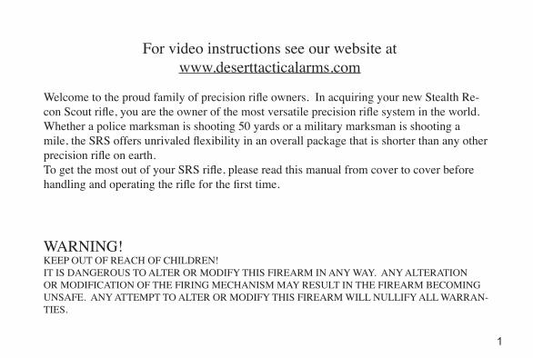
WARNING!KEEP OUT OF REACH OF CHILDREN! IT IS DANGEROUS TO ALTER OR MODIFY THIS FIREARM IN ANY WAY. ANY ALTERATION OR MODIFICATION OF THE FIRING MECHANISM MAY RESULT IN THE FIREARM BECOMING UNSAFE. ANY ATTEMPT TO ALTER OR MODIFY THIS FIREARM WILL NULLIFY ALL WARRAN-TIES.
For video instructions see our website atwww.deserttacticalarms.com
Welcome to the proud family of precision rifle owners. In acquiring your new Stealth Re-con Scout rifle, you are the owner of the most versatile precision rifle system in the world. Whether a police marksman is shooting 50 yards or a military marksman is shooting a mile, the SRS offers unrivaled flexibility in an overall package that is shorter than any other precision rifle on earth.To get the most out of your SRS rifle, please read this manual from cover to cover before handling and operating the rifle for the first time.

2
TABLE OF CONTENTSSAFETY PRECAUTIONS........................................................................................... 4SPECIFICATIONS....................................................................................................... 6FACTS ABOUT THE STEALTH RECON SCOUT.................................................. 8DISASSEMBLY AND ASSEMBLY........................................................................... 14
BUTTPAD.................................................................................................................................. 15BOLT.......................................................................................................................................... 15BARREL.................................................................................................................................... 16MAGAZINE.............................................................................................................................. 20 REMOVING STOCKPANELS................................................................................................. 23
OPERATING INSTRUCTIONS......................................................................................... 24PRECAUTIONS BEFORE FIRING......................................................................................... 24MAGAZINE.............................................................................................................................. 24LOADING AND UNLOADING............................................................................................... 26TRIGGER ADJUSTMENTS..................................................................................................... 29MOUNTING SCOPE................................................................................................................ 31QUICK ZEROING.................................................................................................................... 35

3
INITIAL CLEANING................................................................................................................ 41PERIODIC MAINTENANCE................................................................................................... 41BEFORE AND AFTER FIRING............................................................................................... 46ADDITIONAL DISASSEMBLY & ASSEMBLY..................................................................... 48
BOLT DISASSEMBLY......................................................................................................... 48BOLT ASSEMBLY................................................................................................................ 50
IMMEDIATTE ACTION AND TROUBLE SHOOTING...................................... 53
CARE AND CLEANING........................................................................................... 40
REPAIRS.................................................................................................................................... 59REPLACING BARREL ALIGNMENT PIN......................................................................... 59
PARTS EXPLODED VIEW....................................................................................... 61RIFLE......................................................................................................................................... 61BOLT.......................................................................................................................................... 62 MAGAZINE.............................................................................................................................. 63BUTTSTOCK............................................................................................................................ 64
ACCESSORIES.......................................................................................................... 65
4
Remember that even the safest gun is potentially dangerous to you and others when it is not properly handled. Read carefully the operating instructions and learn how the weapon works and is to be handled.
Make sure that the rifle is unloaded before: • Receiving or handing over the rifle. • Transporting the rifle. • Clearing or disassembly.
Always remove the magazine immediately after firing and make sure that the chamber is empty. Make sure that the fire selector (safety catch) is on “S” (Safe) position to guarantee that the rifle is safe whenever: • Inserting magazine. • You have stopped firing it. • The rifle is being transported or moved. • The rifle is not in use.
SAFETY PRECAUTIONS
5
Before shooting the rifle: • Always wear eye and ear protection. • Always be sure of target backstop and what lies beyond it.
Make sure that the barrel is fully seated and locking screws are tight before firing, as de-scribed on pages 16-18.
Do not use force when disassembling or assembling your weapon. A gun can only be safe as long as it is in a flawless technical condition. Incorrect handling and lack of maintenance may lead to malfunctions and reduced safety of the weapon. Unauthorized modifications to the mechanism, damages caused by the application of force, and modifications effected by third parties will lead to the manufacturer not to assume any liability. Only a DTA certified armorer is allowed to work on the gun.
REMEMBER: ALWAYS ASSUME THAT THE RIFLE IS LOADED: LOOK-ING INTO THE END OF THE BARREL (MUZZLE) IS NOT RECOMMENDED AT ANY TIME.
6
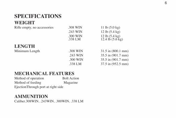
SPECIFICATIONSWEIGHTRifle empty, no accessories .308 WIN 11 lb (5.0 kg) .243 WIN 12 lb (5.4 kg) .300 WIN 12 lb (5.4 kg) .338 LM 12.4 lb (5.6 kg)
LENGTHMinimum Length .308 WIN 31.5 in (800.1 mm) .243 WIN 35.5 in (901.7 mm) .300 WIN 35.5 in (901.7 mm) .338 LM 37.5 in (952.5 mm)
MECHANICAL FEATURESMethod of operation Bolt Action Method of feeding MagazineEjection Through port at right side
AMMUNITIONCaliber .308WIN, .243WIN, .300WIN, .338 LM

7
SIGHTS Picatinny rail (no taper)
BARRELType Match fluted barrel Muzzle Threads .75x24x.625 Length 26 in (660.4mm) Note: .308 WIN length is 22 in FIRING CHARACTERISTICSMuzzle Velocity VariableMaximum Range 1500+ m (1640+ yds)
SAFETIESFire Selector Safe and Fire
8
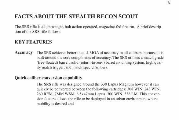
FACTS ABOUT THE STEALTH RECON SCOUT
The SRS rifle is a lightweight, bolt action operated, magazine-fed firearm. A brief descrip-tion of the SRS rifle follows:
KEY FEATURES
Accuracy The SRS achieves better than ½ MOA of accuracy in all calibers, because it is built around the core components of accuracy. The SRS utilizes a match grade (free-floated) barrel, solid (return-to-zero) barrel mounting system, high qual-ity match trigger, and match spec chambers.
The SRS rifle was designed around the 338 Lapua Magnum however it can quickly be converted between the following cartridges: 308 WIN, 243 WIN, 260 REM, 7MM WSM, 6.5x47mm Lapua, 300 WIN, 338 LM. This conver-sion feature allows the rifle to be deployed in an urban environment where mobility is desired and
Quick caliber conversion capability
9
over-penetration is to be avoided, yet you can deploy the same weapon in mountainous terrain where shots can be taken up to a mile away with the .338 Lapua Magnum. Plus, operators only need to learn one system, one rifle and one scope. New shooters can train with the smaller .308 Winchester cartridge, which is easier to shoot and has a barrel life that is four times longer than the .338 LM.
Compact
Rugged
The SRS is the shortest precision rifle system in existence. The SRS is almost a foot shorter than most conventional precision rifles, because it utilizes a bullpup configuration as well as a collapsible bolt design. This compact design shifts the weight rearward creating not only a shorter weapon, but also a perfectly balanced rifle.
The SRS was designed to operate under the harshest conditions and abuse. It utilizes high-impact polymers, aircraft grade aluminums (7075-T6), ultra high strength steels, and the strongest coatings known to man. The operating mechanisms are completely encased by the stock panels except for the ejec-tion port area. The stock panels attach directly to the receiver which acts as
10
full length mounting chassis, eliminating the need for any sort of bedding interface. The SRS sustains its accuracy and reliability in virtually any environment including; subzero temperatures, extreme heat, and wet or dusty environments.
Ergonomics
Ergonomic Feature List
The ergonomics and balance of the SRS are unmatched. We elected to build ergonomics into the weapon itself, instead of adding heavy gadgets and giz-mos as an afterthought.
• Match grade trigger, adjusts for creep, travel, and weight (1 to 6 lbs) and all trig-ger adjustments can be set without disassembling the rifle.
• Adjustable length of pull (1.5” of available adjustment)• Optimized cheek rest, the cheek rest was designed into the rifle to be perfectly
optimized with the height of our proprietary tapered scope rings, thus providing optimal mounting height for any scope with an objective lens of 56mm or less.
11
• Custom contoured pistol grip• Comfortable rear support grip• Raised butt pad, positions the shooters shoulder above the bore line, minimizing
muzzle rise and felt recoil.• Ambidextrous safety selectors are accessible without removing firing hand from
pistol grip.• 60 degree bolt lift• Ambidextrous magazine release buttons easily facilitate one handed magazine
changes so the shooter can stay on the rifle during magazine changes.• Weapons balancing point is approximately ½ inch forward of the trigger guard,
comfortable carrying grip is located at balancing point.• 14 quick sling attachment points are located on the weapon for shooting versatil-
ity, the sling points are also perfectly balanced with the centerline of the weapon to ensure the rifle lies comfortably flat when slung.
Other Benefits• The full length MIL-STD-1913 rail facilitates mounting state of the art night vi-
sion optics, thermal sights, and other mounted accessories.
12
• Our magazines incorporate a “shoulder retention” feature that prevents the projectile tips from slamming into the front of the magazine during recoil. In traditional magazines the projectile tips slam against the front of the magazine, deforming the projectile and in turn diminishing accuracy. This can not happen with our magazine. In addition our internal magazine length is a healthy 3.95” long which is .3” longer than the competitor, making it possible to load the 300+ grain bullets out where they are supposed to be.
• The SRS is available in a variety of color configurations; hard-coated anodizing can be had in either black or olive drab. The stock panel color options are; black, coyote brown, or olive drab.
General Firearm ConstructionRefer to illustration, (see cover)
• The barrel (8) is attached to the receiver (5) by four captive locking screws (4)• The stock panels (1) attach directly to the receiver (5).
13
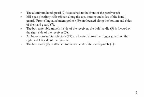
• The aluminum hand guard (7) is attached to the front of the receiver (5)• Mil-spec picatinny rails (6) run along the top, bottom and sides of the hand
guard. Front sling attachment points (19) are located along the bottom and sides of the hand guard (7).
• The bolt assembly travels inside of the receiver; the bolt handle (3) is located on the right side of the receiver (5).
• Ambidextrous safety selectors (17) are located above the trigger guard, on the right and left side of the firearm.
• The butt stock (9) is attached to the rear end of the stock panels (1).
14
DISASSEMBLY AND ASSEMBLY1. This chapter deals with those disassembling and assembling operations which
the user may perform for routine maintenance of the rifle. Disassembling or assembling of any other part is not recommended. Any damage caused from improper disassembly will void warranty.
2. Disassembling must be carried out on a clean surface and disassembled parts should be placed in order of their removal.
WARNING: Carry out the following operations before dismantling: Remove maga-zine; clear the rifle several times to ensure there is no live cartridge in the chamber. (see page 27)
CAUTION: FOREARM IS TEMPORARILY SEALED TO THE RECEIVER. DAMAGE CAUSED BY THE REMOV-
AL OF THE FOREARM WILL VOID WARRANTY!
15
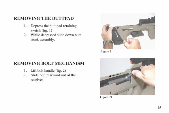
1. Depress the butt pad retaining switch (fig. 1)
2. While depressed slide down butt stock assembly.
REMOVING THE BUTTPAD
1. Lift bolt handle (fig. 2)2. Slide bolt rearward out of the
receiver
REMOVING BOLT MECHANISM
Figure 1
Figure 21
16
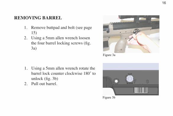
REMOVING BARREL
1. Remove buttpad and bolt (see page 15)
2. Using a 5mm allen wrench loosen the four barrel locking screws (fig. 3a)
1. Using a 5mm allen wrench rotate the barrel lock counter clockwise 180˚ to unlock (fig. 3b)
2. Pull out barrel.
Figure 3a
Figure 3b
17
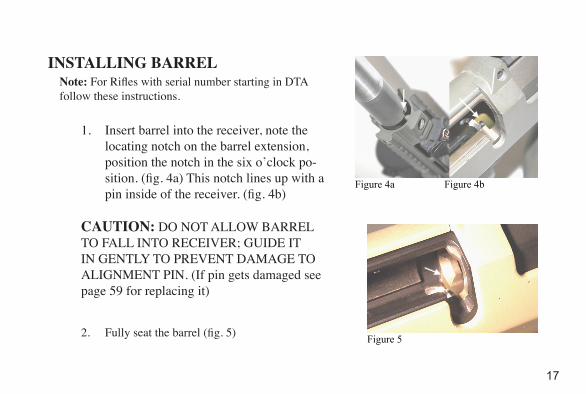
1. Insert barrel into the receiver, note the locating notch on the barrel extension, position the notch in the six o’clock po-sition. (fig. 4a) This notch lines up with a pin inside of the receiver. (fig. 4b)
INSTALLING BARREL
CAUTION: DO NOT ALLOW BARREL TO FALL INTO RECEIVER; GUIDE IT IN GENTLY TO PREVENT DAMAGE TO ALIGNMENT PIN. (If pin gets damaged see page 59 for replacing it)
2. Fully seat the barrel (fig. 5)
Figure 4a Figure 4b
Figure 5
Note: For Rifles with serial number starting in DTA follow these instructions.
18
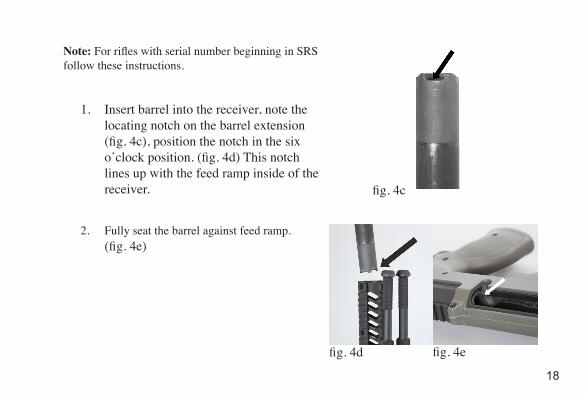
1. Insert barrel into the receiver, note the locating notch on the barrel extension (fig. 4c), position the notch in the six o’clock position. (fig. 4d) This notch lines up with the feed ramp inside of the receiver.
2. Fully seat the barrel against feed ramp. (fig. 4e)
Note: For rifles with serial number beginning in SRS follow these instructions.
fig. 4c
fig. 4d fig. 4e
19
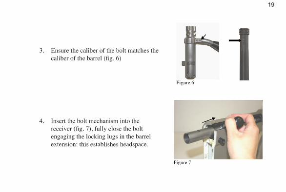
3. Ensure the caliber of the bolt matches the caliber of the barrel (fig. 6)
4. Insert the bolt mechanism into the receiver (fig. 7), fully close the bolt engaging the locking lugs in the barrel extension; this establishes headspace.
Figure 6
Figure 7
20
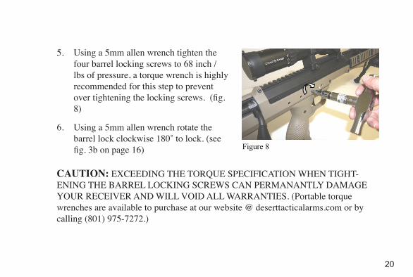
5. Using a 5mm allen wrench tighten the four barrel locking screws to 68 inch / lbs of pressure, a torque wrench is highly recommended for this step to prevent over tightening the locking screws. (fig. 8)
6. Using a 5mm allen wrench rotate the barrel lock clockwise 180˚ to lock. (see fig. 3b on page 16)
Figure 8
CAUTION: EXCEEDING THE TORQUE SPECIFICATION WHEN TIGHT-ENING THE BARREL LOCKING SCREWS CAN PERMANANTLY DAMAGE YOUR RECEIVER AND WILL VOID ALL WARRANTIES. (Portable torque wrenches are available to purchase at our website @ deserttacticalarms.com or by calling (801) 975-7272.)
21
DISASSEMBLY AND ASSEMBLY OF THE MAGAZINE
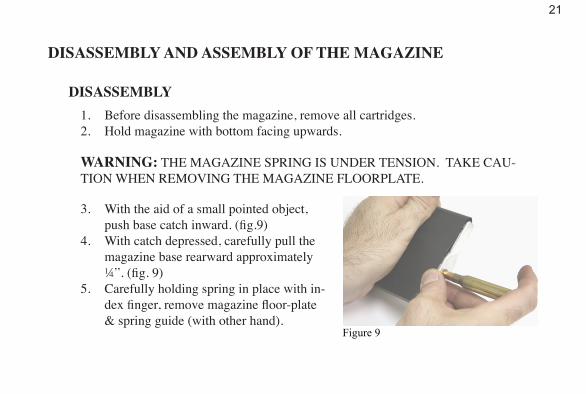
DISASSEMBLY1. Before disassembling the magazine, remove all cartridges.2. Hold magazine with bottom facing upwards.
WARNING: THE MAGAZINE SPRING IS UNDER TENSION. TAKE CAU-TION WHEN REMOVING THE MAGAZINE FLOORPLATE.
3. With the aid of a small pointed object, push base catch inward. (fig.9)
4. With catch depressed, carefully pull the magazine base rearward approximately ¼”. (fig. 9)
5. Carefully holding spring in place with in-dex finger, remove magazine floor-plate & spring guide (with other hand).
Figure 9
22
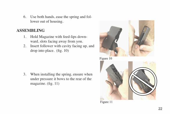
6. Use both hands, ease the spring and fol-lower out of housing.
ASSEMBLING1. Hold Magazine with feed-lips down-
ward, slots facing away from you.2. Insert follower with cavity facing up, and
drop into place. (fig. 10)
3. When installing the spring, ensure when under pressure it bows to the rear of the magazine. (fig. 11)
Figure 10
Figure 11
23
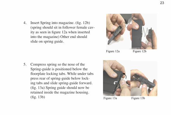
4. Insert Spring into magazine. (fig. 12b) (spring should sit in follower female cav-ity as seen in figure 12a when inserted into the magazine) Other end should slide on spring guide.
5. Compress spring so the nose of the Spring-guide is positioned below the floorplate locking tabs. While under tabs press rear of spring-guide below lock-ing tabs and slide spring-guide forward.(fig. 13a) Spring guide should now be retained inside the magazine housing. (fig. 13b)
Figure 12a Figure 12b
24
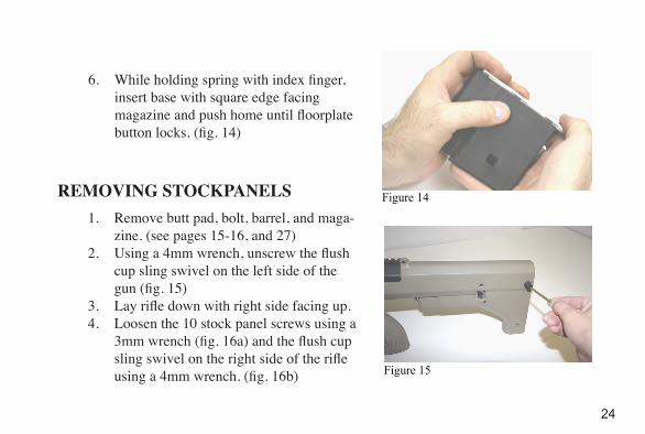
6. While holding spring with index finger, insert base with square edge facing magazine and push home until floorplate button locks. (fig. 14)
1. Remove butt pad, bolt, barrel, and maga-zine. (see pages 15-16, and 27)
2. Using a 4mm wrench, unscrew the flush cup sling swivel on the left side of the gun (fig. 15)
3. Lay rifle down with right side facing up.4. Loosen the 10 stock panel screws using a
3mm wrench (fig. 16a) and the flush cup sling swivel on the right side of the rifle using a 4mm wrench. (fig. 16b)
Figure 14REMOVING STOCKPANELS
Figure 15
25
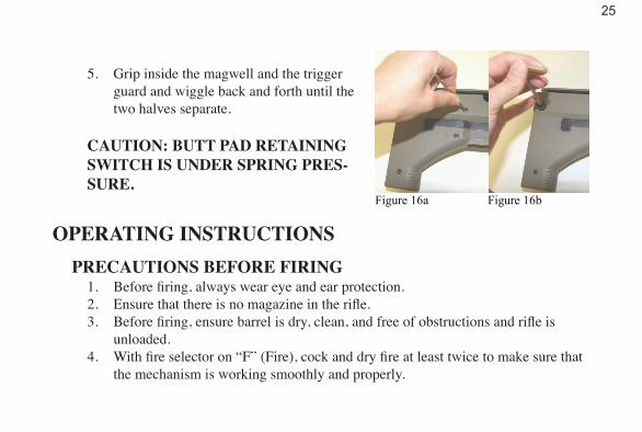
5. Grip inside the magwell and the trigger guard and wiggle back and forth until the two halves separate.
Figure 16a Figure 16b
CAUTION: BUTT PAD RETAINING SWITCH IS UNDER SPRING PRES-SURE.
OPERATING INSTRUCTIONSPRECAUTIONS BEFORE FIRING
1. Before firing, always wear eye and ear protection.2. Ensure that there is no magazine in the rifle.3. Before firing, ensure barrel is dry, clean, and free of obstructions and rifle is
unloaded.4. With fire selector on “F” (Fire), cock and dry fire at least twice to make sure that
the mechanism is working smoothly and properly.
26
5. Run the bolt, return fire selector to “S” (Safe), point barrel in safe direction, squeeze trigger to ensure safety catch is working properly. Return fire selector to “F” (Fire) and dry fire. Set fire select to “S” (Safe).
6. Never put your finger inside the trigger guard or squeeze trigger unless you are ready to fire. From the time the magazine is inserted, until the rifle is cleared and clearance is checked, keep rifle pointed in a safe direction.
7. Fire selector should always be on “S” (Safe) until you are ready to fire.8. Check that magazines are clean and properly loaded.
FILLING & EMPTYING THE MAGAZINE
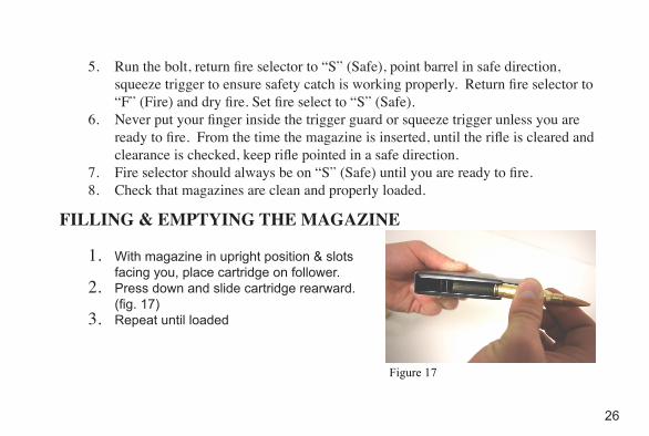
1. With magazine in upright position & slots facing you, place cartridge on follower.
2. Press down and slide cartridge rearward. (fig. 17)
3. Repeat until loaded
Figure 17
27
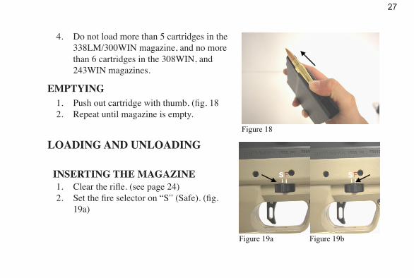
4. Do not load more than 5 cartridges in the 338LM/300WIN magazine, and no more than 6 cartridges in the 308WIN, and 243WIN magazines.
Figure 18
EMPTYING1. Push out cartridge with thumb. (fig. 182. Repeat until magazine is empty.
LOADING AND UNLOADING
INSERTING THE MAGAZINE1. Clear the rifle. (see page 24)2. Set the fire selector on “S” (Safe). (fig.
19a)
Figure 19a Figure 19b
28
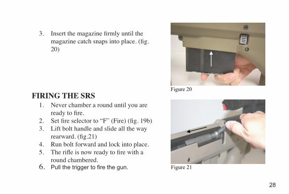
3. Insert the magazine firmly until the magazine catch snaps into place. (fig. 20)
Figure 20 FIRING THE SRS
1. Never chamber a round until you are ready to fire.
2. Set fire selector to “F” (Fire) (fig. 19b)3. Lift bolt handle and slide all the way
rearward. (fig.21)4. Run bolt forward and lock into place.5. The rifle is now ready to fire with a
round chambered.6. Pull the trigger to fire the gun. Figure 21
29
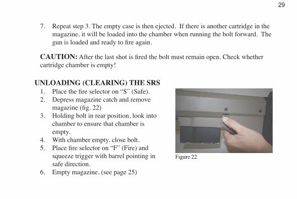
7. Repeat step 3. The empty case is then ejected. If there is another cartridge in the magazine, it will be loaded into the chamber when running the bolt forward. The gun is loaded and ready to fire again.
CAUTION: After the last shot is fired the bolt must remain open. Check whether cartridge chamber is empty!
UNLOADING (CLEARING) THE SRS1. Place the fire selector on “S” (Safe). 2. Depress magazine catch and remove
magazine (fig. 22)3. Holding bolt in rear position, look into
chamber to ensure that chamber is empty.
4. With chamber empty, close bolt.5. Place fire selector on “F” (Fire) and
squeeze trigger with barrel pointing in safe direction.
6. Empty magazine. (see page 25)
Figure 22
30
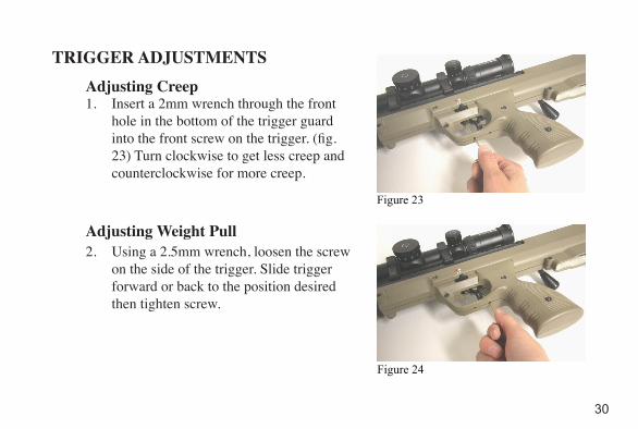
TRIGGER ADJUSTMENTSAdjusting Creep1. Insert a 2mm wrench through the front
hole in the bottom of the trigger guard into the front screw on the trigger. (fig. 23) Turn clockwise to get less creep and counterclockwise for more creep.
Adjusting Weight Pull2. Using a 2.5mm wrench, loosen the screw
on the side of the trigger. Slide trigger forward or back to the position desired then tighten screw.
Figure 23
Figure 24
31
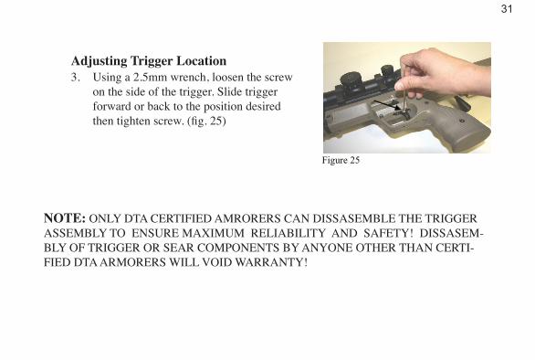
Adjusting Trigger Location3. Using a 2.5mm wrench, loosen the screw
on the side of the trigger. Slide trigger forward or back to the position desired then tighten screw. (fig. 25)
NOTE: ONLY DTA CERTIFIED AMRORERS CAN DISSASEMBLE THE TRIGGER ASSEMBLY TO ENSURE MAXIMUM RELIABILITY AND SAFETY! DISSASEM-BLY OF TRIGGER OR SEAR COMPONENTS BY ANYONE OTHER THAN CERTI-FIED DTA ARMORERS WILL VOID WARRANTY!
Figure 25
32
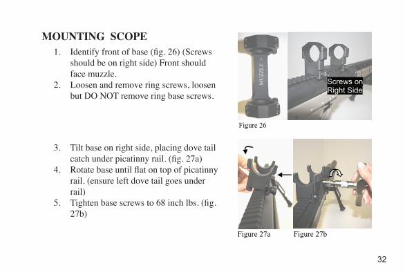
MOUNTING SCOPE1. Identify front of base (fig. 26) (Screws
should be on right side) Front should face muzzle.
2. Loosen and remove ring screws, loosen but DO NOT remove ring base screws.
3. Tilt base on right side, placing dove tail catch under picatinny rail. (fig. 27a)
4. Rotate base until flat on top of picatinny rail. (ensure left dove tail goes under rail)
5. Tighten base screws to 68 inch lbs. (fig. 27b)
MU
ZZLE
>
Screws on Right Side
Figure 26
Figure 27a Figure 27b
33
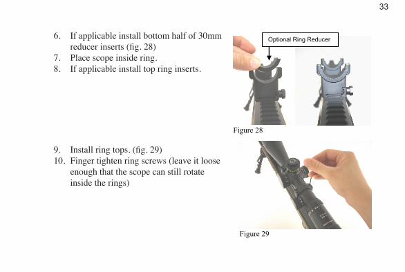
6. If applicable install bottom half of 30mm reducer inserts (fig. 28)
7. Place scope inside ring.8. If applicable install top ring inserts.
9. Install ring tops. (fig. 29)10. Finger tighten ring screws (leave it loose
enough that the scope can still rotate inside the rings)
Figure 28
Optional Ring Reducer
Figure 29
34
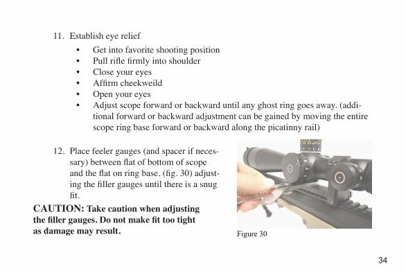
• Get into favorite shooting position• Pull rifle firmly into shoulder• Close your eyes• Affirm cheekweild• Open your eyes• Adjust scope forward or backward until any ghost ring goes away. (addi-
tional forward or backward adjustment can be gained by moving the entire scope ring base forward or backward along the picatinny rail)
11. Establish eye relief
12. Place feeler gauges (and spacer if neces-sary) between flat of bottom of scope and the flat on ring base, (fig. 30) adjust-ing the filler gauges until there is a snug fit.
CAUTION: Take caution when adjustingthe filler gauges. Do not make fit too tightas damage may result.
Figure 30

35
13. Tighten ring screws to 15 in lb, rotating from left to right in a criss cross pattern. While you tighten, ensure filler gauges are not too tight. They should always have some left to right play.
36
QUICK ZEROING1. Find center of scope, place windage & elevation turret in center of travel range.
• First identify your scopes adjustment values (MOA or MIL).• Determine total windage and elevation adjustment from scopes literature
or by turning the knobs from one end to the other while viewing a bore sighter. Note – many scope’s knobs will rotate beyond the erector cells available movement, thus at the extreme ends of the knobs travel the reticle will stop moving before the knob stops.
CAUTION: DO NOT FORCE SCOPE KNOBS WHEN YOU REACH THE END OF TRAVEL RANGE
• Once total travel has been determined, rotate windage clockwise all the way.
• Once windage knob stops, rotate the knob back out in the counter clock-wise motion by half of the total windage travel.
• e. Rotate elevation knob until it bottoms out.
37
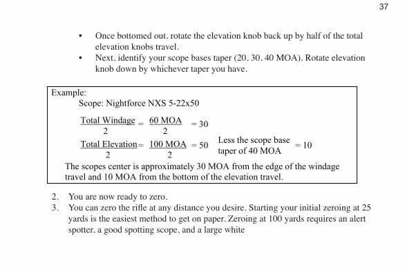
• Once bottomed out, rotate the elevation knob back up by half of the total elevation knobs travel.
• Next, identify your scope bases taper (20, 30, 40 MOA). Rotate elevation knob down by whichever taper you have.
Example: Scope: Nightforce NXS 5-22x50 = = 30
= = 50 = 10
The scopes center is approximately 30 MOA from the edge of the windage travel and 10 MOA from the bottom of the elevation travel.
60 MOA 2 100 MOA 2
Less the scope base taper of 40 MOA
Total Windage 2 Total Elevation 2
2. You are now ready to zero.3. You can zero the rifle at any distance you desire. Starting your initial zeroing at 25
yards is the easiest method to get on paper. Zeroing at 100 yards requires an alert spotter, a good spotting scope, and a large white
38
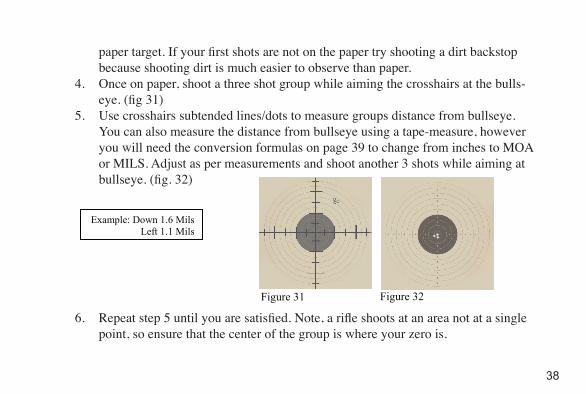
paper target. If your first shots are not on the paper try shooting a dirt backstop because shooting dirt is much easier to observe than paper.
4. Once on paper, shoot a three shot group while aiming the crosshairs at the bulls-eye. (fig 31)
5. Use crosshairs subtended lines/dots to measure groups distance from bullseye. You can also measure the distance from bullseye using a tape-measure, however you will need the conversion formulas on page 39 to change from inches to MOA or MILS. Adjust as per measurements and shoot another 3 shots while aiming at bullseye. (fig. 32)
Example: Down 1.6 Mils Left 1.1 Mils
Figure 32
Figure 31
6. Repeat step 5 until you are satisfied. Note, a rifle shoots at an area not at a single point, so ensure that the center of the group is where your zero is.
39
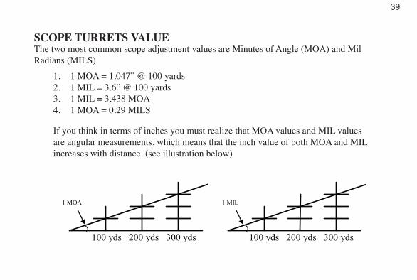
SCOPE TURRETS VALUE The two most common scope adjustment values are Minutes of Angle (MOA) and Mil Radians (MILS)
1. 1 MOA = 1.047” @ 100 yards2. 1 MIL = 3.6” @ 100 yards3. 1 MIL = 3.438 MOA4. 1 MOA = 0.29 MILS
If you think in terms of inches you must realize that MOA values and MIL values are angular measurements, which means that the inch value of both MOA and MIL increases with distance. (see illustration below)
100 yds 200 yds 300 yds
1 MIL
100 yds 200 yds 300 yds
1 MOA
40
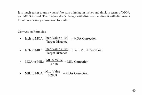
It is much easier to train yourself to stop thinking in inches and think in terms of MOA and MILS instead. Their values don’t change with distance therefore it will eliminate a lot of unnecessary conversion formulas.
Conversion Formulas
• Inch to MOA: = MOA Correction
• Inch to MIL: ÷ 3.6 = MIL Correction
• MOA to MIL: = MIL Correction
• MIL to MOA: = MOA Correction
Inch Value x 100 Target Distance
Inch Value x 100 Target Distance
MOA Value 3.438
MIL Value 0.2908
41
CARE AND CLEANING
GENERALComprehensive knowledge of how to service and handle rifles is of great importance. Experience has shown that most failures which occur while operating the rifle are due to negligence in maintenance. Special attention must be paid to cleaning, lubricat-ing and inspecting the rifle; this will determine whether or not the rifle will function properly when you need it. In order to maintain accuracy, the barrel must be serviced thoroughly. The receiver, the bolt assembly and other moving parts of the rifle must be kept clean and lightly lubricated to ensure proper operation. Care and cleaning in-cludes the magazine, which must be kept free from rust, grit, etc., in order to function properly.
42
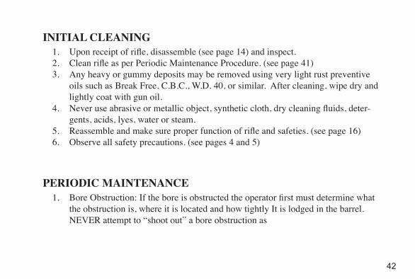
INITIAL CLEANING1. Upon receipt of rifle, disassemble (see page 14) and inspect.2. Clean rifle as per Periodic Maintenance Procedure. (see page 41)3. Any heavy or gummy deposits may be removed using very light rust preventive
oils such as Break Free, C.B.C., W.D. 40, or similar. After cleaning, wipe dry and lightly coat with gun oil.
4. Never use abrasive or metallic object, synthetic cloth, dry cleaning fluids, deter-gents, acids, lyes, water or steam.
5. Reassemble and make sure proper function of rifle and safeties. (see page 16)6. Observe all safety precautions. (see pages 4 and 5)
PERIODIC MAINTENANCE1. Bore Obstruction: If the bore is obstructed the operator first must determine what
the obstruction is, where it is located and how tightly It is lodged in the barrel. NEVER attempt to “shoot out” a bore obstruction as

43
damage to the system may occur (as well as possible operator injury). Snow and/or ice can generally be pushed out with a cleaning rod w/patch. Should it not be possible to move it in this manner, it can be warmed until it either melts or loosens sufficiently to allow a push out. Sand, mud and dirt can present a challenge to the operator and care must be taken to ensure that the bore is not damaged during removal. As much debris as possible should be removed by shaking out the barrel (while pointed in a safe direction) prior to lubricating the bore with “Break Free” and pushing out with a patch.
2. Bore Fouling: Ideally, the bore should be cleaned every 40 rounds in a thorough fashion utilizing a proper one piece cleaning rod, a jag, a bronze brush, a pull through, and cleaning patches to ensure optimum accuracy. Should field condi-tions not allow a cleaning at 40 rounds the operator can be confident of acceptable accuracy well beyond this threshold, however a proper cleaning becomes critical to accuracy after 80 rounds has been fired. We suggest the following procedure to clean our rifle barrels:
• Remove butt pad and bolt (see page 15).• Insert bore guide.

44
• Wet patch with Shooter’s Choice bore cleaner and push through.• Brush thoroughly with sized bronze brush and Shooter’s Choice making at
least two full passes for every shot fired since the last cleaning.• Allow to sit for 15 minutes• Push patch through wet with Shooter’s Choice.• Patch with 4 dry patches or until patches come out dry and clean.• Run patch through bore wet with Sweet’s 7.62 bore solvent and let sit for
NO LONGER than 10 minutes.• Patch with a clean dry patch. If there is blue residue on the patch repeat
the cleaning process until no blue residue remains on the final stage.• Once the bore is clean, utilize the pull through w/patch saturated with
Shooter’s Choice in a back and forth motion for 10 strokes.• Push through 4 dry patches or until patches come out dry and clean.
3. Muzzle Brake: Ensure that the vents are clear of debris and occasionally check to ensure the brake has not “shot loose”.
45
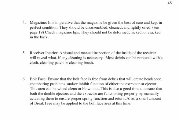
4. Magazine: It is imperative that the magazine be given the best of care and kept in perfect condition. They should be disassembled, cleaned, and lightly oiled. (see page 19) Check magazine lips. They should not be deformed, nicked, or cracked in the back.
5. Receiver Interior: A visual and manual inspection of the inside of the receiver will reveal what, if any cleaning is necessary. Most debris can be removed with a cloth, cleaning patch or cleaning brush.
6. Bolt Face: Ensure that the bolt face is free from debris that will create headspace, chambering problems, and/or inhibit function of either the extractor or ejector. This area can be wiped clean or blown out. This is also a good time to ensure that both the double ejectors and the extractor are functioning properly by manually actuating them to ensure proper spring function and return. Also, a small amount of Break Free may be applied to the bolt face area at this time.
46
7. Bolt Interior: The operator should occasionally remove the firing pin assembly from the bolt (see page 48). Wipe this area clean prior to applying a small amount of Break Free.
8. General Cleaning: The entire rifle should be wiped off with a clean cloth lightly saturated with Break Free on occasion. This includes the barreled action, scope rings, and ancillary components.
47
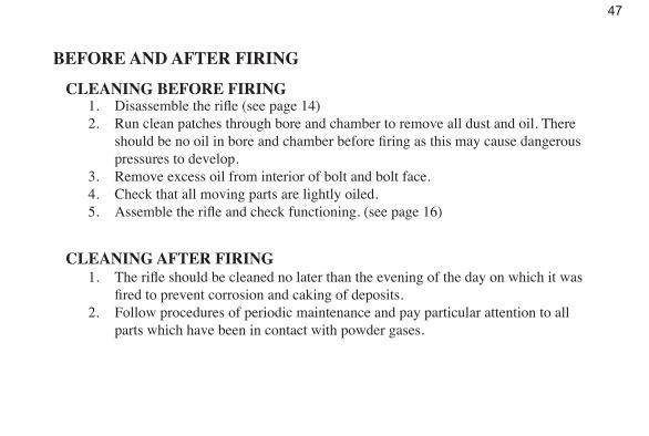
BEFORE AND AFTER FIRING
CLEANING BEFORE FIRING1. Disassemble the rifle (see page 14)2. Run clean patches through bore and chamber to remove all dust and oil. There
should be no oil in bore and chamber before firing as this may cause dangerous pressures to develop.
3. Remove excess oil from interior of bolt and bolt face.4. Check that all moving parts are lightly oiled.5. Assemble the rifle and check functioning. (see page 16)
CLEANING AFTER FIRING1. The rifle should be cleaned no later than the evening of the day on which it was
fired to prevent corrosion and caking of deposits.2. Follow procedures of periodic maintenance and pay particular attention to all
parts which have been in contact with powder gases.

48
• Barrel: In order to remove heavy deposits, use cleaning brush. Make sure the brush goes all the way through the bore before reversing the direction. Deposits that cannot be readily removed with the brush may be treated by coating bore & chamber with good quality bore & chamber fluid and allowing to soak for at least twelve hours.
• After soaking, repeat above procedure. The barrel should be cleaned and re-oiled, at least once on the day after firing.
• Firing Mechanism – Remove all powder residues from bolt face and interior surfaces of bolt. If necessary, use stiff nylon brush or tooth brush.
• Receiver: Wipe off any heavy deposits in interior and oil lightly.• Magazine: Make sure magazines are clean and follower moves freely.
49
ADDITIONAL DISASSEMBLY & ASSEMBLY
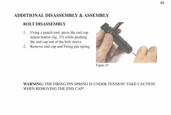
BOLT DISASSEMBLY
1. Using a punch tool, press the end cap detent button (fig. 33) while pushing the end cap out of the bolt sleeve.
2. Remove end cap and Firing pin spring.
Figure 33
WARNING: THE FIRING PIN SPRING IS UNDER TENSION! TAKE CAUTION WHEN REMOVING THE END CAP!
50
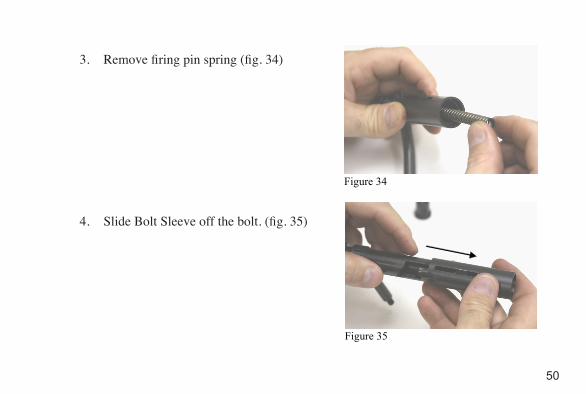
3. Remove firing pin spring (fig. 34)
4. Slide Bolt Sleeve off the bolt. (fig. 35)
Figure 34
Figure 35
51
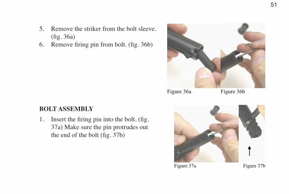
5. Remove the striker from the bolt sleeve. (fig. 36a)
6. Remove firing pin from bolt. (fig. 36b)
BOLT ASSEMBLY1. Insert the firing pin into the bolt. (fig.
37a) Make sure the pin protrudes out the end of the bolt (fig. 37b)
Figure 36a Figure 36b
Figure 37a Figure 37b
52
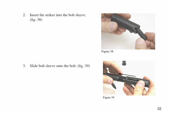
2. Insert the striker into the bolt sleeve. (fig. 38)
3. Slide bolt sleeve onto the bolt. (fig. 39)
Figure 38
Figure 39
53
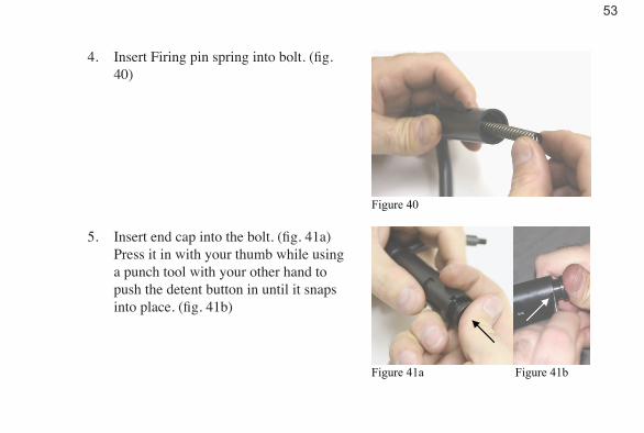
4. Insert Firing pin spring into bolt. (fig. 40)
5. Insert end cap into the bolt. (fig. 41a) Press it in with your thumb while using a punch tool with your other hand to push the detent button in until it snaps into place. (fig. 41b)
Figure 40
Figure 41a Figure 41b
54
IMMEDIATE ACTION AND TROUBLE SHOOTING
A failure to fire (including one caused by an empty magazine) may often be corrected by taking immediate action.
IMMEDIATE ACTIONRemove magazine and wait 3 seconds with barrel pointing in a safe direction, then inspect magazine.
1. MAGAZINE EMPTYCock to remove possible last round. Inspect chamber and if empty, insert full magazine, run the bolt and continue firing.
55
2. MAGAZINE NOT EMPTY (Malfunction)• Run the bolt and clean possible defective or wrongly posi-
tioned round. If a round or case ejects, inspect chamber and if empty, reload and continue firing.
• If nothing ejects, fully draw back bolt and check if cartridge or case is in chamber. If empty, reload and continue firing.
• If base of cartridge is visible, close bolt and fire in a safe direction. If rifle fires and ejects, reload and continue.
• If rifle does not fire, set fire selector on “S” (Safe) and fol-low “spent case or round stuck in chamber”. (see page 58)
56
TROUBLE SHOOTING
A. FAILURE TO FEED
CAUSE
* Rifle jams or closes on empty chamber
REMEDY
1. Incorrect Cocking2. Poor Magazine3. Magazine Improperly Seated4. Magazine Improperly Loaded
5. Dirty Magazine6. Damaged Magazine7. Double Feed
Clear jam if necessary and run boltReplace with DTA factory magazinePush magazine home until latch catchesa. Seat top cartridge properlyb. Check that no more than 5 rounds are in the
MagazineDisassemble and CleanReplacea. Inspect for stuck case or cartridge (see sec-
tion E. on page 58)b. Check extractor and ejector (see section D.
on page 57)
57
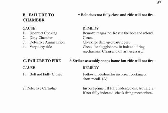
B. FAILURE TOCHAMBER
* Bolt does not fully close and rifle will not fire.
CAUSE1. Incorrect Cocking2. Dirty Chamber3. Defective Ammunition4. Very dirty rifle
REMEDYRemove magazine. Re run the bolt and reload.Clean.Check for damaged cartridges.Check for sluggishness in bolt and firing mechanism. Clean and oil as necessary.
C. FAILURE TO FIRE * Striker assembly snaps home but rifle will not fire.
CAUSE REMEDY
1. Bolt not Fully Closed
2. Defective Cartridge
Follow procedure for incorrect cocking or short recoil. (A)
Inspect primer. If fully indented discard safely. If not fully indented, check firing mechanism.

58
3. Dirty Firing Mechanism Defective Firing Pin Defective Striker Assembly
Check for sluggishness of operation.
4. Barrel Not Properly Seated
Clean and replace as necessary.
Make sure the locating notch on the barrel extension lines up with the pin inside of the receiver and is fully seated. (see pages 16-17)
D. FAILURE TO EXTRACT OR EJECT
The fired case may not eject, or the rifle may jam (spent case left in chamber).
CAUSE REMEDY
1. Overpowered Ammunition (Stuck Case)
2. Dirty or Damaged Chamber
Check ammunition and change to a different brand of currently commercially manufactured ammunition if problem persists.
Inspect, clean, replace barrel if necessary.

59
3. Defective Ammunition
4. Fouled Extractor5. Extractor Defective or Missing6. Damaged Ejector
Check ammunition for damage. Replace if problem persists.Clean ExtractorReplaceReplace if necessary
E. SPENT CASE OR ROUND STUCK IN CHAMBER
Caution: The following procedure should be carried out only after following the steps in “Immediate Action”. (see pages 53 & 54 – 2b, c, d)
1. Remove bolt and striker assembly.2. With barrel in place, insert cleaning rod through front of barrel. Push or tap gen-
tly to remove obstruction.3. Check chamber and bore. Clean before reassembly.4. If obstruction cannot be removed, disassemble barrel and contact authorized
service station.
60
REPAIRS
REPLACING FIRING PIN1. Disassemble the bolt (see page 48)2. Insert new firing pin3. Assemble the bolt (see page 50)
STORAGE

61
WARNING!KEEP OUT OF REACH OF CHILDREN! IT IS DANGEROUS TO ALTER OR MODIFY THIS FIREARM IN ANY WAY. ANY ALTERATION OR MODIFICATION OF THE FIRING MECHANISM MAY RESULT IN THE FIREARM BECOMING UNSAFE. ANY ATTEMPT TO ALTER OR MODIFY THIS FIREARM WILL NULLIFY ALL WARRANTIES.
62
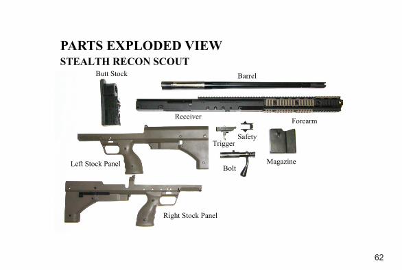
PARTS EXPLODED VIEW STEALTH RECON SCOUT
Right Stock Panel
Left Stock Panel
Receiver
Magazine Bolt
Safety Trigger
Forearm
Barrel Butt Stock
63
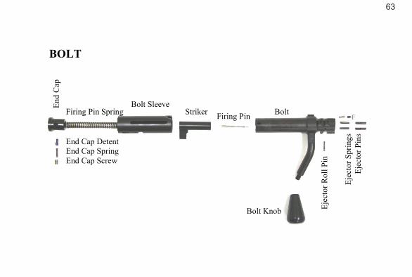
BOLT
Ej
ecto
r Spr
ings
Ej
ecto
r Pin
s
Ejec
tor R
oll P
in
Bolt Knob
End Cap Detent End Cap Spring End Cap Screw
Bolt Sleeve Firing Pin Spring
End
Cap
Firing Pin Striker Bolt
64
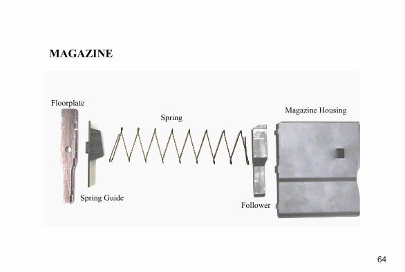
MAGAZINE
Floorplate
Spring
Follower Spring Guide
Magazine Housing
65
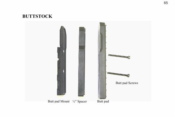
BUTTSTOCK ½” Spacer Butt pad Butt pad Mount
Butt pad Screws

66
ACCESSORIESDay ScopesNight VisionTapered Scope ringsSuppressorHard CaseRifle Matt CarrierMagazinesBipods and Adapters SlingsRail CoversField Cleaning KitBench Cleaning KitToolsSpare parts kit Armorer ToolsScope Installation & Zeroing Kit
67
Stealth Recon Scout US Patent D584,373PATENTS PENDING
No part of this document may be copied, reproduced, or transmitted by any means, for any purpose without permission from Desert Tactical Arms, Inc.
All images and text © 2008-2009 DTA, Inc.
LIMITATION OF LIABILITYThe liability of Desert Tactical Arms, Inc. for any and all losses/and or damage to the
purchase shall in no event exceed the purchase price of the Rifle. In no event shall Desert Tactical Arms, Inc. be liable for incidental or consequential damage. User assumes all risks
and liabilities arising from the use of this product.


PO Box 65816
Salt Lake City, Utah 84165 Phone (801) 975-7272 Fax (801) 908-6425
Deserttacticalarms.com