Embed Size (px)
Citation preview

EZ Dock® Floating Docks
Owner’s Manual and Installation Instructions for Dock Sections, Anchoring, and Accessories
Installation Instructions
The first dock of its kind...The last dock you will ever need®.
DOCKMANUAL-2011
For questions about features, operation/performance, parts, accessories or service, call your local dealer or your nearest EZ Dock distributor at
1-800-654-8168 or +1-417-235-2223 for international customers.
Additional information regarding EZ Dock products and services can be found on the internet at www.ez-dock.com

2
Table of Contents General Information and Installation Overview………………………………………………...……….3 EZ Dock Specifications………………….…….…...……………………….……………………............4 1 Model/Serial Number…………………………………………………………………………………...5 2 Site Preparation.…….…………………...….……………………………….…...…………………….5 3 Dock Section Orientation Coupler and Installation……....………………………………… ………6 4 Selecting Your Anchoring……….…………………………...………………………………………...7 5 Pipe Anchoring…………………………………………………………………..………….…….........9 Piling Anchoring………………………………………………………………….….………….12 Deadweight Anchoring…………………………………………………………………...........16 Stiff-Arm Anchoring……………………………………………………………………………..20 6 Gangways…………….………………………………………………………………………………...23 Float Hinge Kit…………………………………………………………………………………...24 Abutment Hinge Kit……………………………………………………………………………..24 Transition Plate………………………………………………………………………………….24 Gangway Roller Kit & Roller…………………………………………………………………...24 Aluminum Gangway…………………………………………………………………………….25 Polyethylene Gangway……………………………………………………………….………..25 Gangplank Mounting Kit………………………………………………………………………..28 Polyethylene Plank……………………………………………………………………………...28 7 Accessories…...………………………………………………………………………………………..29 Corner Gusset….........…………………………………………….…………………………...29 Utility Channel…………………………………………………………………………………..29 Corner Storage Box………………………….…………………………………………………30 Large Storage Box………………………………………………………………….…………..31 Swim Ladder……………………………………………………………….……………………32 Float Step Ladder……………………………………………………………………………...33 Bench……………………………………………………………………………………………34 8‖ Nylon Tie-Up Cleat.…………….…………………………………………………………...35 12‖ Galvanized Tie-Up Cleat………………………………………………………………….35 Bumper……………………………..…………………………………………………………...36 Dock Edging…………………………………………………………………………………….36 Security Curbing………………………………………………………………………………...37 Handrails……………………………..………………………………………………………….38 8 Warranty/Customer Service...….…….….…………………………………………………………...39 9 Maintaining your EZ Dock……........….……………………………………..……..………………...39
Dear EZ Dock Owner, The EZ Dock team thanks you for your purchase. We know that you had other choices of docks, and we ap-preciate your decision to purchase EZ Dock. You will find it easy to maintain your EZ Dock products and to add accessories and other components to your dock in the future. EZ Dock is the most durable dock on the market, and your friends and family will enjoy your dock for many years to come. Before you install your new EZ Dock, please take a moment to register your dock warranty. You can register online at www.ez-dock.com or by using the warranty registration card provided by your distributor/dealer. By registering your product, you will activate your product warranty and thereby protect your purchase against covered product defects. Please feel free to give your EZ Dock customer service department a call with any issues that you may have with your EZ Dock. You can reach our customer service department by dialing: USA/Canada: 1-800-654-8168 Int’l: 1-417-235-2223 Europe: +46 (0) 380 47 300
3
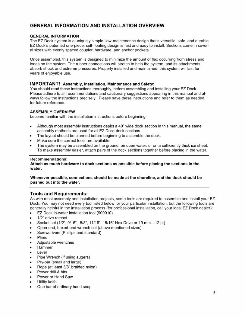
Tools and Requirements: As with most assembly and installation projects, some tools are required to assemble and install your EZ Dock. You may not need every tool listed below for your particular installation, but the following tools are generally helpful in the installation process (for professional installation, call your local EZ Dock dealer):
EZ Dock in-water installation tool (900010)
1/2‖ drive ratchet
Socket set (1/2‖, 9/16‖, 5/8‖, 11/16‖, 15/16‖ Hex Drive or 19 mm—12 pt)
Open-end, boxed-end wrench set (above mentioned sizes)
Screwdrivers (Phillips and standard)
Pliers
Adjustable wrenches
Hammer
Level
Pipe Wrench (if using augers)
Pry-bar (small and large)
Rope (at least 3/8‖ braided nylon)
Power drill & bits
Power or Hand Saw
Utility knife
One bar of ordinary hand soap
GENERAL INFORMATION AND INSTALLATION OVERVIEW GENERAL INFORMATION The EZ Dock system is a uniquely simple, low-maintenance design that’s versatile, safe, and durable. EZ Dock’s patented one-piece, self-floating design is fast and easy to install. Sections come in sever-al sizes with evenly spaced coupler, hardware, and anchor pockets. Once assembled, this system is designed to minimize the amount of flex occurring from stress and loads on the system. The rubber connections will stretch to help the system, and its attachments, absorb shock and extreme pressures. Properly installed and maintained, this system will last for years of enjoyable use.
IMPORTANT! Assembly, Installation, Maintenance and Safety:
You should read these instructions thoroughly, before assembling and installing your EZ Dock. Please adhere to all recommendations and cautionary suggestions appearing in this manual and al-ways follow the instructions precisely. Please save these instructions and refer to them as needed for future reference. ASSEMBLY OVERVIEW become familiar with the installation instructions before beginning
Although most assembly instructions depict a 40‖ wide dock section in this manual, the same assembly methods are used for all EZ Dock dock sections.
The layout should be planned before beginning to assemble the dock.
Make sure the correct tools are available.
The system may be assembled on the ground, on open water, or on a sufficiently thick ice sheet. To make assembly easier, attach pairs of the dock sections together before placing in the water.
Recommendations: Attach as much hardware to dock sections as possible before placing the sections in the water. Whenever possible, connections should be made at the shoreline, and the dock should be pushed out into the water.
4
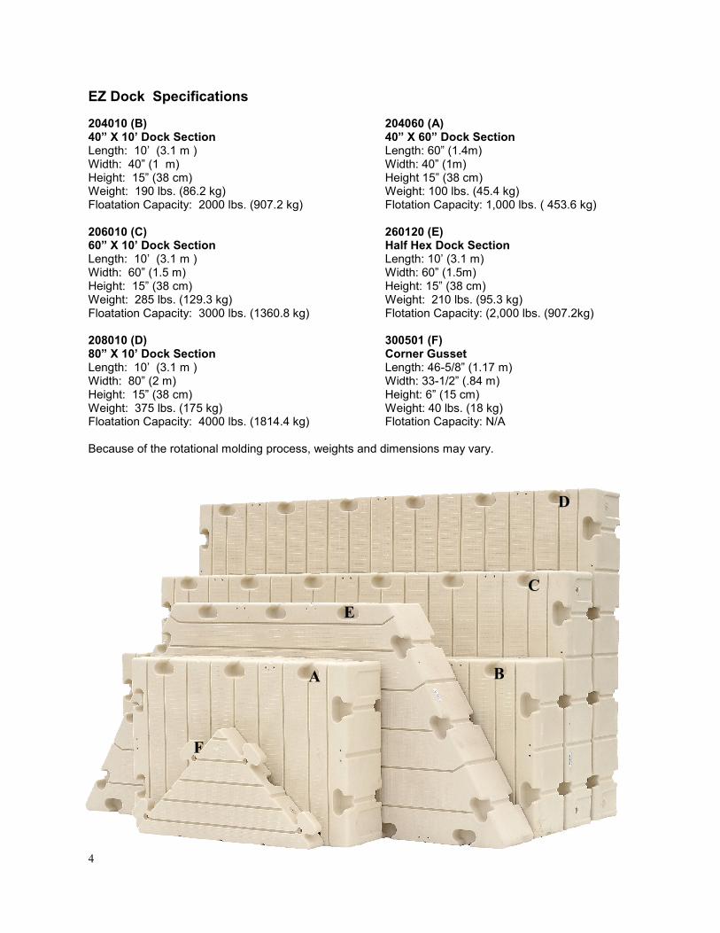
EZ Dock Specifications
204010 (B) 204060 (A) 40” X 10’ Dock Section 40” X 60” Dock Section Length: 10’ (3.1 m ) Length: 60‖ (1.4m) Width: 40‖ (1 m) Width: 40‖ (1m) Height: 15‖ (38 cm) Height 15‖ (38 cm) Weight: 190 lbs. (86.2 kg) Weight: 100 lbs. (45.4 kg) Floatation Capacity: 2000 lbs. (907.2 kg) Flotation Capacity: 1,000 lbs. ( 453.6 kg) 206010 (C) 260120 (E) 60” X 10’ Dock Section Half Hex Dock Section Length: 10’ (3.1 m ) Length: 10’ (3.1 m) Width: 60‖ (1.5 m) Width: 60‖ (1.5m) Height: 15‖ (38 cm) Height: 15‖ (38 cm) Weight: 285 lbs. (129.3 kg) Weight: 210 lbs. (95.3 kg) Floatation Capacity: 3000 lbs. (1360.8 kg) Flotation Capacity: (2,000 lbs. (907.2kg) 208010 (D) 300501 (F) 80” X 10’ Dock Section Corner Gusset Length: 10’ (3.1 m ) Length: 46-5/8‖ (1.17 m) Width: 80‖ (2 m) Width: 33-1/2‖ (.84 m) Height: 15‖ (38 cm) Height: 6‖ (15 cm) Weight: 375 lbs. (175 kg) Weight: 40 lbs. (18 kg) Floatation Capacity: 4000 lbs. (1814.4 kg) Flotation Capacity: N/A Because of the rotational molding process, weights and dimensions may vary.
F
C
D
E
B A

5
Each EZ Dock installation is site specific and needs to be configured specifically for the end user’s intended application. Some factors to take into consideration when determining the components nec-essary for a proper installation include; intended usage, water conditions, soil and bed conditions, and climatic conditions. Listed below are simple rules to follow.
Be certain that your installation configuration is designed to accommodate the daily intended use of your EZ Dock. Please take into account the following:
Commercial application needs
Public access requirements (ADA, CORP, or other)
Private docking needs
Scale of operation and use (size of boats, number of PWCs, number of people, etc.)
Other special considerations affecting your daily use Be aware of the unique characteristics of the specific body of water and consider how such conditions will affect the installation. Take into account:
Overall area of the body of water
Water depth (at the shore and at the furthest point of the dock from shore)
Normal and greatest wave action
Water level fluctuation
Fresh, brackish, or salt-water
Normal and extraordinary ice thickness and movement
Lake bed and soil conditions (sand, rock, mud, etc.)
Determine whether your installation will be attended to and inspected on a regular basis.
Become acquainted with the normal movement associated with floating structures.
Determine whether you are capable of performing your own installation or whether it is best to hire a professional by contacting your local EZ Dock dealer.
Site Preparation
Model/Serial Number You should register your EZ Dock product to ensure proper warranty coverage. The location of the serial number may be difficult or impossible to see once installed, so we suggest that you create a record of your serial numbers and corresponding dock sections to insure proper identi-fication when filing a warranty claim. The serial numbers can be found on the vertical side wall on the logo end of the dock sections. See photo below.

6
Sites with severe wave conditions need to arrange docks so pylons are parallel to wave action and vents are facing against a dock face or towards the shore to minimize excess water collect-ing in docks. Once you have considered and worked out the issues above, the next step is to select the anchoring method that is best for you. Since no two installations are ever exactly the same, each and every EZ Dock installation must be designed and configured for the specific and intended application.
Dock Placement in Relationship to Shore
Prevailing Wind or Wave Direction After the prevailing wind and wave direc-
tions have been established it will be nec-essary to design the dock system so that the dock length is parallel to such direc-tion. This will allow the EZ Dock patented couplers to flex properly. Refer to the dia-gram to the right for further details.
Every EZ Dock section has at least one hydrophobic venting insert. These are typically located in one end (see above left on the same end that the bar code graphic is. These vents are designed to reduce any amounts of water that may enter the dock but still allow the dock section to breath with temperature variation. When possible these vents should be positions towards shore and away from prevailing wind/current direction.
ITEM QTY. PART NO. DESCRIPTION
1 1 9000028 HYDROPHOBIC VENT 1/4” NPT
2 1 103565 SPINWELD 1.9"-1/4" FPT FLUSH EZD

7
Coupler Installation (301100)
1. Insert the composite coupler bolt into coupler. Align the mark on the head of the bolt so the splines line up into the notched pockets in the coupler. 2. Using a hammer, seat the bolt into the coupler. 3. Install coupler with seated bolt on the in- water installation tool. 4. Align dock sections so coupler pockets
are adjacent to each other, and using the in-water in-stallation tool, insert the coupler and bolt assembly into the bottom pocket with the bolt pointing upward.
DO NOT OVER TIGHTEN THE NUT! Torque to 15 ft. lbs.
Helpful Hint: To make assembly and disassembling easier,
rub a bar of hand soap on the coupler rods to lubricate them.
5. Pull up on the in-water installation tool to seat the bottom coupler. (NOTE: The dock sections must be sitting level on the water and at the same elevation for the coupler to properly seat into the bottom pocket. Sometimes it is helpful to ballast the opposing ends of dock sections to keep the adjoining ends from dipping. This can be done by having someone stand on the opposite ends of each dock section, or by standing on an elevated beam or board (as shown) placed perpendicular to the dock section to span the seam being connected. When coupling seams together, it is recommended to start at the center of the seam and work to the edges.
Drowning Hazard
Swimming under and/or attempting to breathe in cavities under EZ Dock docks and ports while performing in-water installation of docks, ports and couplers can result in accidental drowning and death.
Do not attempt in-water installation without EZ Dock in-water coupler installation tools.
DANGER
Note:
All empty or un-used coupler pockets should
be filled with an EZ Dock pocket filler (201030); see page 38.

8
Anchoring
Once you have selected your site and assembled the dock, the next step is to select the anchoring method best suited for your location. Since no two installations are ever exactly the same, each and every EZ Dock installation must be designed and configured for your specific application. Your local dealer can help you select the anchoring system that is right for your location. EZ Dock offers a wide variety of anchoring components which are simple to install and safe to use. Constructed of either poly-ethylene, galvanized steel, or stainless steel (all of which are long lasting, durable materials that can range from standard to heavy duty) they both provide a wide range of reliable options to construct a dock for nearly any use and waterscape. Selecting your Anchoring Method
EZ Dock provides a wide range of anchoring components to accommodate most water conditions and bottoms (deep, shallow, rough, or sandy). EZ Dock anchoring methods are simple to install and safe to use. Our anchoring products are made from long-lasting, durable materials that can accommodate from standard to heavy-duty demands.
Pipe anchoring is typically used in most private and some light duty commercial applications.
The deadweight method of anchoring is used with deeper water or rocky bottoms.
Piling anchoring is very similar to pipe anchoring in that the pilings are used to prevent the lateral movement of the dock. This method of anchoring is used in heavy duty commercial applications.
Stiff-arm anchoring is a method of supporting the dock system by attachment to the shore or some other type of rigid structure by poles or arms.
In-Water Coupler Installation Tool (9000010)
1. Align and abut the adjoining ends of the dock sections . 2. Insert the bottom coupler and bolt assembly into installation tool and firmly pull up to seat coupler. 3. Hold the top handle and lower the tool with coupler into the water until the rod is completely below the bottom surface of the dock section. (If the rod hits the dock section the coupler may fall off the tool).
4. While maintaining the proper depth, slide the tool between the dock sections until you reach the pocket to be connected. 5. Lift the tool upward while aligning the rod to come up between the opening through the pockets. The tool has a 1/2‖ hole on the long flat part of the handle that may be seen above the deck area and will indicate that the bottom coupler is properly in position. Insert a rod or screwdriver into this hole to hold the tool and coupler in place while connecting top coupler. 6. Place top coupler into position, thread on coupler nut, and draw the connections together tightly. 7. To release the installation tool, remove pin from hole and push down tool, sliding it between the docks and begin your next coupler
installation. For help contact your dealer or distributor at 800-654-8168.

9
Pipe anchoring is our most popular type of anchoring using a small diameter pipe to provide the hori-zontal support necessary to keep the docks in place. The use of pipe will allow the docks to move up and down with most water fluctuations, and with little maintenance . This method of anchoring utilizes either a heavy-duty or a standard-duty pipe bracket that is typically used in most private and some light duty commercial installations. The size and number of pipe needed will be determined by conditions encountered.
Anchoring Pipe and Auger Installation
The auger is attached to the bottom of the pipe
to allow easier installation of pipe anchoring.
The auger works well with muddy or sandy
bottoms .
Pipe Anchoring
Pipe is normally embedded or screwed into the bed of the body of water a distance of three to eight feet (roughly 1/4 to 1/3 the total length of the pipe). Wave action should not exceed three feet, and water depths should not exceed 12 feet for the 250 series bracket or 18 feet for the 350 series bracket.
Pipes can be used to secure an EZ Port. When pipes are used they must be sufficiently embedded or screwed into the lake, river or ocean bed to a depth of at least three feet. The EZ Port will not hold the pipe upright, the pipe should remain vertical and hold the EZ Port in place.
It is recommended to use pipe augers, except in rocky or shale bottoms, to make installation easier. Augers allow the pipe to be turned into the lake, river or ocean bed like a cork screw using a pipe wrench or by drilling the hole for the pipe and using a T-handle.
Pipe diameter: Pipe brackets are available for two pipe sizes 2-1/2‖ and 3-1/2‖. A 2‖ bracket is de-signed to use pipe that measures 2-1/2‖ in outside diameter and a 3‖ bracket is designed to use pipe that measures 3-1/2‖. The installation process is the same for either pipe size.
In salt water or brackish water conditions it is recommended that the steel pipe be sleeved with PVC pipe. The steel pipe will need to fit inside the 2-1/2‖ or 3-1/2‖ pipe. This will help prevent abrasion and wear on the pipe bracket, prevent rust, and improve appearance.
Determine the length and size of pipe needed and bracket locations.

10
The auger is attached to the bottom of the pipe to allow easier installation of pipe anchoring in lake, river, or ocean bottoms. The auger works well in sandy or muddy bottoms.
Pipe Brackets
Standard-Duty Pipe Bracket (130250 or 130350)
The standard-duty bracket is designed for residential use or to anchor EZ Port PWC lifts. For installation wave action should not exceed 1.5 to 2 feet and water depths should not exceed 8 feet for 2‖ pipe or 12 feet for 3‖ pipe. The standard-duty bracket is simple to install, connecting to a single set of pockets that may be placed anywhere around the perimeter of the dock. It is always best to locate at least one bracket near the shore end of the dock. The other brackets may be placed along the sides or at the ends of the dock.
The heavy-duty pipe bracket is designed for residential and light commercial applications which must allow docks to ad-just to changing water levels. Wave action should not exceed 2.5 to 3 feet. Water depths should not exceed 12 feet for 2‖ pipe or 18 feet for 3‖ pipe. It is always best to locate at least one bracket near the shore end of the dock. The remaining brackets may be placed along the sides or at the end of the dock. You never want to span a seam restricting the move-ment of the dock creating more stress on the couplers. Two sets of pockets are required to connect the bracket to the dock.
Heavy-Duty Pipe Bracket (210250 or 210350)
EZ Dock pipe brackets are available in a standard-duty or heavy-duty models. Each type of bracket is capable of using 2-1/2‖ or 3-1/2‖ pipe depending on your needs.
Pipe Auger (100255 or 100355)
Anchoring Pipe Specifications
For part numbers ending with ...025, component will be 2.5‖ OD 10 gauge, galvanized pipe. For part numbers ending with ...035, component will be 3.5‖ OD 8 gauge, galvanized pipe.

11
Tools Required: Ratchet 1/2‖ socket 1/2‖ wrench Large pipe wrench 1. Slide the polyethylene bracket halves over the top of the pipe
as shown. The two halves of the bracket are identical. 2. Align the pipe next to the dock where it is to be attached. The
pipe should be placed so that it is centered with a pocket. 3. Install the bottom half of the bracket by inserting the molded
on coupler into the bottom pocket of the dock or lift. 4. Attach the top half of the bracket by inserting the molded on
coupler into the top pocket of the dock or lift. 5. Secure the two halves together using the sup-
plied 5/16‖ bolts and nuts. 6. Plumb the anchoring pipe with a level, then
turn or drive the pipe into the soil until it is completely secure.
Standard-Duty Pipe Bracket Installation (130250, 130250, and 130251)
Heavy-Duty Pipe Bracket Installation (210250 and 210350)
1. Slide the insert over the top of the pipe to be installed. 2. Align the pipe next to the dock where it will be attached. It should be placed so that the sleeve is centered between two pockets. Auger or drive the pipe into the bottom until it will stand by itself, but still can easily be adjusted for proper positioning. 3. Slide the sleeve inserts up the pipe far enough so that the
main frame can be brought around the pipe and into posi-tion against the dock.
4 Attach the polyethylene main frame to the dock using a standard coupler set. Refer to coupler installation instruc-tions.
5. Slide the insert sleeve down the pipe and into the polyethylene main frame, adjusting pipe loca-tion if necessary. Secure the insert sleeve with the two 5/16‖ ( 80514SS) bolts.
6. Finish driving or screwing the pipe into the bottom so that it is solidly in place, the minimum depth of the pipe is three feet.
Tools Required: Ratchet 15/16‖ Socket Hammer #4 Phillips Screwdriver
ITEM QTY. PART NO. DESCRIPTION
1 1 N/A ANCHORAGE PIPE
2 2 10014 SD PIPE BRAKCET HALF
3 N/A N/A DOCK OR PORT SECTION
4, 5 1 S13025 PARTS CARTON
ITEM QTY. PART NO. DESCRIPTION
1 1 N/A ANCHORAGE PIPE
2 1 10004 POLYETHYLENE PIPE INSERT
3 1 10015 POLYETHYLENE MAIN FRAME
5 2 80514SS BOLT 5/16” SS

12
Anchoring Pipe and Auger Installation
Tools Required:
Drill
Drill Bit (3/8‖ for 2-1/2‖ augers)
Drill Bit (1/2‖ for 3-1/2‖ augers)
Ratchet
9/16‖ or 15 mm socket and wrench
3/4‖ or 19 mm socket and wrench
Pipe Wrench (optional) 1. Determine the length and size of pipe needed. 2. Insert auger butt into the end of the pipe and drill a 3/8‖ hole through the pipe and auger at the same time. 3. Insert bolt that is provided through the hole and tighten with the lock nut that is provided.
Note: Sometimes it is necessary to grind the shank of the auger to allow it to fit inside the pipe.
NOTES:
ITEM QTY. PART NO. DESCRIPTION
1 1 10355 AUGER—3 1/2”
2 1 TOOL DRIVE TOOL
3 1 N/A ANCHORAGE PIPE
4 2 80124 BOLT 1/2”-13 X 4” SS
5 2 80119YZ NUT 1/2”-13 HEX

13
Piling Anchoring
The heavy duty piling bracket is recommended for deep water levels or severe conditions such as heavy wave or wind action or when a large craft are to be moored to the dock system. The piling needs to be driven a minimum of 3’ into the bed when you have moderate water going deeper with rougher water. Some of the harsh environments where the use of pilings should be considered are shown below.
Where vessels of thirty feet or longer are to be moored.
Where the water depth is greater than 18 feet.
Where there are extreme winds and/or currents to contend with.
When large water fluctuations are present.
Where severe ice conditions are present and would cause the smaller pipe to bend and/or be jacked out.
Pilings typically range from six to twenty-four inches in diameter and are driven into body of water from seven to forty feet.

14
Heavy-Duty Piling Bracket (300800)
The heavy-duty piling bracket is recommended for deep water or severe conditions such as heavy wind or wave action or when larger craft will be moored to the dock sys-tem. The bracket has multiple coupler pockets for easier alignment to existing pilings. It can be coupled with any pocket configuration to allow the piling to center in the piling bracket. You never want to span a seam, as re-stricting the movement of the dock will create more stress on the couplers. Position the adjustable steel rollers in various configurations to fit pilings from 6‖ to 18‖.
The standard-duty piling bracket is designed for deep water installations, more severe conditions such as heavy wave or wind action, or when larger vessels will be moored to the dock system. The standard-duty piling bracket can be adjust-ed to accommodate existing pilings. We have several hoop sizes to accommodate any piling you may have. Be certain there is sufficient clearance between the hoop and piling so the dock can move freely with water level changes.
Piling Brackets (100800)
Standard-Duty Piling Bracket (100800) Piling Hoop (100804, 100806, 100808, 100812, 100816, 100820, & 100824)
The piling brackets are available in two models, a standard-duty and heavy-duty. Both brackets are designed for variable adjustment to attach to existing piles.
NOTES:

15
Hoop Assembly Installation
1. Place hoop insert into the hole at the end of the hoop.
2. Insert 3/8‖-16 X 2‖ hex bolt through top of hoop and hoop insert. Secure with 3/8‖-16 hex nut.
3. Insert the hooked end of the hoop brace into the pre-drilled hole in the bottom of the hoop.
4. Rotate the brace clockwise until it fits snugly inside the hoop. 5. Center hoop assembly around the pile and insert ends of the hoop brace into the cor-
responding holes on the bottom of the piling bracket. 6. Apply pressure while pulling the hoop up and towards the dock until the ends of the
hoop are flush with the top of the bracket. 7. Insert 5/8‖-11 X 1‖ hex cap screws through the top holes of the bracket and into the
threaded end of the hoop insert.
Standard-Duty Piling Bracket Installation
1. Loosely attach two hardware connectors to the bottom of the adjustable piling bracket.
2. Place two hardware connectors into the top pockets of the dock section where the piling bracket is to be installed.
3. Next, guide the bracket and previously installed bottom hardware con-nectors (tapered side up) so that the bottom connectors are brought up and fully seated into the bottom pockets.
4. Move the bracket in towards the dock so the top two hardware connect-ors align with the mount holes in the bracket.
5. Secure the bracket to the dock by fully threading the enclosed 5/8‖ lock nuts. Install piling, and if using existing piling, make sure that the hoop can go around piling and mount into hoop mount holes on each side.
ITEM QTY. PART NO. DESCRIPTION
1 2 80382 BOLT 3/8”-16 X 2”
2 2 80381 NUT 3/8”-16
3 1 N/A PILING
4 2 80058 BOLT 5/8”-11 X 1 HHCS GRD 5
5 4 80580SS NUT 5/8” SS
6 2 S10800 PILING GUSSET ARM
7 1 S10801 PILING HOOP INSERT
8 2 S10803 PILING HOOP BRACE GUSSET 21”
9 1 N/A PILING HOOP
10 4 S21140SS HDW CONNECTOR MALE 5/8” SS

16
1. Place the two bottom roller assemblies into the bottom in either the forward or backward position. For pilings up to 12‖ diameter or smaller, use the forward position. For pilings larger than 12‖ use the rear roller position.
2. Place the top half of the piling bracket on top of the lower half as shown and bolt them together using the 5/16‖ X 3-1/2‖ bolts (80535SS) and nuts (80095-15).
3. Attach the piling bracket to the dock in the desired pocket location and secure using two standard coupler sets.
4. After you have the piling bracket around the piling and centered, place the remaining roller assembly into one of the top roller cradles. It is important to leave 1‖ to 1-1/2‖ clearance between the rollers and piling so that the dock may move freely with changing water level.
5. Place the roller covers over the roller cradles on the top bracket and secure using four 5/16‖ X 1-1/2‖ truss head bolts (805755SS).
The heavy-duty piling bracket can be coupled with any pocket configuration to allow the piling to center in the piling bracket. You never want to span a seam, as restricting the movement of the dock will create more stress on the couplers.
Heavy Duty Piling Bracket Installation
ITEM QTY. PART NO. DESCRIPTION
1 2 S20800 POLY. ADJ PILING BRACKET
2 2 80535SS BOLT 5/16”-18 X 3-1/2” HEX
3 2 80518 NUT 5/16”-18 NYLOCK HEX
4 2 S221875 ANGLE RETAINER 18-3/8”L SS
5 4 80575SS BOLT 5/16”X 3/4” TRUSS HEAD SS
6 3 S20801SS ROLLER ASSEMBLY PILING
7 4 117003 WASHER 5/16” FLAT

17
Deadweight Anchoring
Deadweight anchoring is a method of supporting the dock system by placing a large weight on the bed of the body of water. It is then attached to the dock by means of chain, cable, or synthetic line. This large weight serves to hold the docks in place where, due to ice, deep water, poor piling condi-tions, or aesthetics, pipe doesn’t work. Anchoring docks by deadweights is more difficult to design and install. When determining the number and placement of the deadweights, there are no set rules or formulas. These systems will require adjusting as water levels fluctuate. It is very important that the customer understands what needs to be done to maintain the system. EZ Dock offer 4 types of deadweight anchoring brackets to consider when ordering components. Deadweight anchoring requires equal pairs of weights to keep resistance the same on both sides. The heavy-duty pipe bracket has two options. If the water fluctuates on a regular basis, you may want to use the deadweight winch insert. If your dock system is located in a protected area, our standard-duty deadweight bracket may be sufficient. Installing deadweight anchoring will require the use of a heavy duty pipe bracket (210350) with a deadweight insert (100725P) or winch insert (100730), a mid-weight bracket (100700), or a standard duty deadweight bracket (100740 or 100740SS). When possible, chain should be the primarily choice for all dead weight installations. In waters that fluctuate frequently the use of a ―tawning‖ weight may be necessary. Tawning weights are smaller weights (50-200 lbs.) placed 2/3 the distance of the maximum water fluctuation from the primary deadweight. This will allow tension on the chain at lower tide levels. As a general rule, deadweights need to placed in opposing pairs at a 30° angle from the dock and the chain length should be roughly 3-4 times the water depth away from the dock.

18
Heavy-Duty Bracket Deadweight (210350 100725P or 100730)
The standard-duty deadweight bracket is designed for applications with water depths greater than 12 feet. Using pipe brackets work well in calm or deep water. The bracket has a key hole slot to attach your chain. Or the bracket maybe used to attach 4 X 4 railing for mooring posts.
Deadweight Bracket (100700)
When water conditions are more severe and you need more than the small deadweight, but not the larger one, this bracket is what you need. It has the same slotted features to hold the chain in place.
Deadweight Brackets (100740 100740SS)
There are three brackets ranging from light duty to heavy duty that work well for deadweight an-choring your EZ Dock. The heavy duty bracket will allow you to use a chain insert or a winch to quickly and easily adjust your dock to frequently changing water levels.
The deadweight is available with a deadweight insert (100725P) or a deadweight winch insert (100730) to attach deadweights to anchor EZ Dock sections. When using the winch, the cable can be easily adjusted for various water condi-tions. The deadweight inserts come ready to insert into an EZ Dock heavy duty polyethylene pipe bracket. The pipe bracket, insert, and ca-ble needed for the installation are sold sepa-rately.
Standard-Duty Bracket (100740 or 100740SS)

19
Standard Duty Deadweight Bracket Installation
1. Insert the hardware connector in the bottom pocket as shown. 2. Slide hooked portion of bracket into top pocket of the dock and bring bottom portion down over the hardware connector. 3. Secure bracket to hardware connector with the
5/8‖ lock nut: *Fully thread nut into place. *Do not over tighten.
Mid-weight Duty Deadweight Bracket Installation
1. Loosely attach two hardware connectors (tapered side up) to the inside/bottom of the deadweight bracket mainframe using the 5/8‖ lock nuts.
2. Place two hardware connectors into the top pock-ets of the dock where the deadweight bracket is to be positioned.
3. Guide the bracket so the lower hardware connect-ors are brought fully up into the bottom pockets.
4. Move the bracket in toward the dock so the top hardware connector bolts will protrude through the corresponding holes in the mainframe. Secure by fully threading with 5/8‖ lock nuts being careful not to over tighten.
5. Attach chain and weights.
ITEM QTY. PART NO. DESCRIPTION
1 1 S10740** SD DEAD WEIGHT BRACKET
2 1 S21140SS HARDWARE CONNECTOR 5/8” MALE
3 1 80580SS NUT 5/8” SELF LOCKING
ITEM QTY. PART NO. DESCRIPTION
1 4 80580SS NUT 5/8” SELF LOCKING
2 1 S10701 MD DEAD WEIGHT BRACKET
3 4 S21140SS HARDWARE CONNECTOR 5/8” MALE

20
The HD deadweight bracket (210350) is available with a deadweight insert (100725P) or a deadweight winch insert (100730) to attach deadweights to anchor EZ Dock sections. When using the winch, the cable can be easily adjusted for various water conditions. The deadweight inserts come ready to insert into an EZ Dock heavy duty polyethylene pipe bracket. The pipe bracket, insert, and cable needed for the installation are sold separately. Tools Required: Hammer 15/16‖ Socket Ratchet Composite Coupler Tool #2 Phillips Screw Driver 9/16‖ Open End Wrench 1. Install the heavy duty pipe bracket. 2. Slide either the deadweight insert or winch insert in the main-
frame. 3. Secure the insert with two 5/16‖ machine bolts found in small
parts bag.
Heavy Duty Deadweight Bracket Installation
ITEM QTY. PART NO. DESCRIPTION
1 1 10004 POLY PIPE BRACKET INSERT 3.5” BROWN
2 1 10015 POLYETHYLENE MAIN FRAME
3 1 92600 WINCH 2600LB
4 2 80514SS BOLTS 5/16”
5 1 S10730 WINCH POST INSERT
ITEM QTY. PART NO. DESCRIPTION
1 1 10004 POLY PIPE BRACKET INSERT 3.5” BROWN
2 1 10015 POLYETHYLENE MAIN FRAME
3 2 80514SS BOLTS 5/16”
4 1 100725P DEADWEIGHT INSERT PVC
21
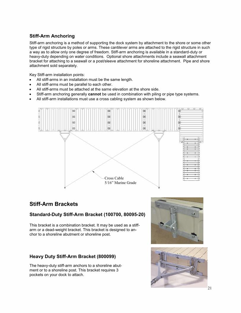
Stiff-Arm Anchoring
Stiff-arm anchoring is a method of supporting the dock system by attachment to the shore or some other type of rigid structure by poles or arms. These cantilever arms are attached to the rigid structure in such a way as to allow only one degree of freedom. Stiff-arm anchoring is available in a standard-duty or heavy-duty depending on water conditions. Optional shore attachments include a seawall attachment bracket for attaching to a seawall or a post/sleeve attachment for shoreline attachment. Pipe and shore attachment sold separately. Key Stiff-arm installation points:
All stiff-arms in an installation must be the same length.
All stiff-arms must be parallel to each other.
All stiff-arms must be attached at the same elevation at the shore side.
Stiff-arm anchoring generally cannot be used in combination with piling or pipe type systems.
All stiff-arm installations must use a cross cabling system as shown below.
Stiff-Arm Brackets
Standard-Duty Stiff-Arm Bracket (100700, 80095-20)
Heavy Duty Stiff-Arm Bracket (800099)
This bracket is a combination bracket. It may be used as a stiff-arm or a dead-weight bracket. This bracket is designed to an-chor to a shoreline abutment or shoreline post.
The heavy-duty stiff-arm anchors to a shoreline abut-ment or to a shoreline post. This bracket requires 3 pockets on your dock to attach.
Cross Cable
5/16” Marine Grade
22
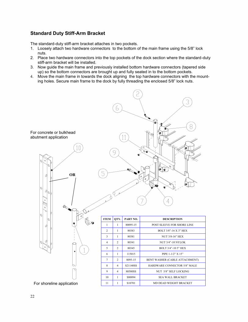
Standard Duty Stiff-Arm Bracket
The standard-duty stiff-arm bracket attaches in two pockets. 1. Loosely attach two hardware connectors to the bottom of the main frame using the 5/8‖ lock
nuts. 2. Place two hardware connectors into the top pockets of the dock section where the standard-duty
stiff-arm bracket will be installed. 3. Now guide the main frame and previously installed bottom hardware connectors (tapered side
up) so the bottom connectors are brought up and fully seated in to the bottom pockets. 4. Move the main frame in towards the dock aligning the top hardware connectors with the mount-
ing holes. Secure main frame to the dock by fully threading the enclosed 5/8‖ lock nuts.
OR
For concrete or bulkhead abutment application
For shoreline application
ITEM QTY. PART NO. DESCRIPTION
1 1 80095-15 POST SLEEVE FOR SHORE LINE
2 1 80383 BOLT 3/8”-16 X 3” HEX
3 1 80381 NUT 3/8-16” HEX
4 2 80341 NUT 3/4”-10 NYLOK
5 2 80345 BOLT 3/4”-10 5” HEX
6 1 115015 PIPE 1-1/2” X 15”
7 2 8095-15 BENT WASHER (CABLE ATTACHMENT)
8 4 S21140SS HARDWARE CONNECTOR 5/8” MALE
9 4 80580SS NUT 5/8” SELF LOCKING
10 1 S80094 SEA WALL BRACKET
11 1 S10701 MD DEAD WEIGHT BRACKET

23
Heavy Duty Stiff-Arm Bracket (800099)
Tool Requirements: Ratchet 15/16‖ Socket Hammer 1. Loosely attach three hardware connectors to the bottom of the main frame (tapered side up). 2. Place three hardware connectors into top pockets of the dock section where stiff-arm bracket is to be
installed. Next guide main frame and previously installed bottom hardware connectors so the bottom of the connectors are brought up and fully seated into the bottom pockets.
3. Move the main frame in towards the dock so the top three hardware connectors align with the mount-ing holes in the top; rail of the main frame. Secure main frame to dock by fully threading the enclosed 5/8‖ lock nuts being careful not to over tighten.
OR
For concrete or bulkhead abutment application
For shoreline application
ITEM QTY. PART NO. DESCRIPTION
1 3 80124 BOLT 1/2”-13 X 4”
2 1 N/A ANCHORAGE PIPE (SHORE LINE)
3 2 80341 NUT 3/4”-10 NYLOK
4 2 80345 BOLT 3/4”-10 5” HEX
5 2 80342SS WASHER 3/4” SS
6 3 80119YZ NUT 1/2”-13 HEX
7 1 80095-15 POST SLEEVE FOR SHORE LINE
8 2 80900 PIPE STOP
9 6 80580SS NUT 5/8” SELF LOCKING
10 6 S21140SS HARDWARE CONNECTOR 5/8” MALE
11 1 S80090 MAIN FRAME TO DOCK BRK
12 1 S80091 A-FRAME YOKE BRK
13 1 S80094 SEA WALL BRACKET
14 1 N/A ANCHORAGE PIPE 2-3/8”

24
Access is an important feature of your dock system. EZ Dock has several different options available to meet your access requirements, whether it be residential, commercial, or special needs. Gang-ways are hinged to adjust with changing water levels. EZ Dock gangways are designed to attach to a seawall or concrete abutment using an abutment hinge assembly or a float hinge assembly to al-low your dock to sit on the shore with rollers to move in and out with changing water levels.
Aluminum Gangway (G101208-G101216, G100308-G100324, G100408-G100424, & G100508-G100524)
These gangways have a welded aluminum walkway structure with custom aluminum extrusions and welded aluminum handrails that are bolted into place. Lengths of the gangways are from 8’ to 24’ and widths of 2’, 3’, 4’ and 5’. The aluminum gangways are strong and durable with a cool, slip-resistant ThruFlow™ decking surface that can be used for virtually any application. They are also avail-able without decking.
Polyethylene Gangway Section (400406)
The polyethylene gangway section is 48 inches wide to also meet special needs requirements in 6 foot length. You are able to attach three of the polyethylene gangway sections together with compo-nents designed specifically for the polyethylene gangway, allowing you to have an 18’ gangway. Handrails are also available for added safety. Kits contain all of the necessary hardware to assemble to your gangway (G101XXX).
GANGWAYS
Wooden Gangplank Mounting Kit (100240, 100340, & 100600)
The wooden gangplank mounting kit includes a galvanized steel hinge bracket, and the attaching hardware. Lengths of the gangplank vary with the kit you select. Selection of the proper width is important, as the weight of a gangplank that is too wide can cause the first dock section to list. When using the 100240, your gangplank may be 12’ long. With a 100340, your gangplank may be 8’ long. With a 100600, your gang-plank may be 6’ long. It is available in 24‖, 34‖, and 60‖ widths. Lengths are based on the gangplank being attached to a system con-taining at least three dock sections. Lumber is not included. Optional shore-end hinge brackets and roller kits are available.
Polyethylene Plank Mounting Kit (200200)
The polyethylene plank mounting kit is a hinged polyeth-ylene panel used to create a smooth transition between shore grade and deck surface.
25
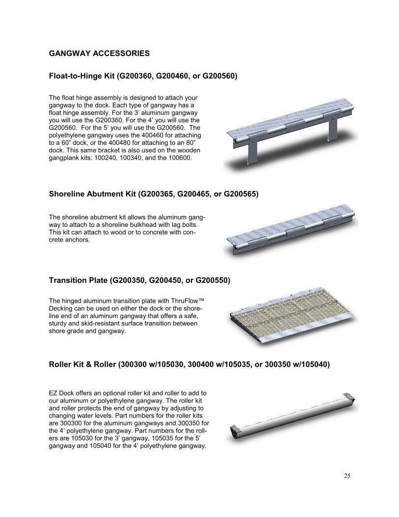
Float-to-Hinge Kit (G200360, G200460, or G200560)
The float hinge assembly is designed to attach your gangway to the dock. Each type of gangway has a float hinge assembly. For the 3’ aluminum gangway you will use the G200360. For the 4’ you will use the G200560. For the 5’ you will use the G200560. The polyethylene gangway uses the 400460 for attaching to a 60‖ dock, or the 400480 for attaching to an 80‖ dock. This same bracket is also used on the wooden gangplank kits: 100240, 100340, and the 100600.
Roller Kit & Roller (300300 w/105030, 300400 w/105035, or 300350 w/105040)
Shoreline Abutment Kit (G200365, G200465, or G200565)
EZ Dock offers an optional roller kit and roller to add to our aluminum or polyethylene gangway. The roller kit and roller protects the end of gangway by adjusting to changing water levels. Part numbers for the roller kits are 300300 for the aluminum gangways and 300350 for the 4’ polyethylene gangway. Part numbers for the roll-ers are 105030 for the 3’ gangway, 105035 for the 5’ gangway and 105040 for the 4’ polyethylene gangway.
Transition Plate (G200350, G200450, or G200550)
The hinged aluminum transition plate with ThruFlow™ Decking can be used on either the dock or the shore-line end of an aluminum gangway that offers a safe, sturdy and skid-resistant surface transition between shore grade and gangway.
The shoreline abutment kit allows the aluminum gang-way to attach to a shoreline bulkhead with lag bolts. This kit can attach to wood or to concrete with con-crete anchors.
GANGWAY ACCESSORIES

26
Tools Required: Phillips Screwdriver Ratchet and socket set Open-end, boxed-end wrench set Traditional hand or electric saw Tape measure 1. Attach the two handrail sections to the
gangway base using the nuts, bolts, and washers provided. Make sure the bolts are tight but not over tightened.
2. Remove the interlocking tabs on only one end of the first and last panel of ThruFlow™ Decking with a saw. All other interlocking tabs not located on the end of the gangway are to be left alone.
3. Lay out all decking panels centered on the gangway and attach with decking screws provided.
Polyethylene Gangway Connection Plate & Truss Support Installation
Tools Required: Drill 3/8‖ X 7‖ drill bit #4 Phillips Screw Driver 9/16‖ Open End Wrench or Socket 1. Lay out the gangway sections with
the walking surface down. 2. Bolt the connection plates to the
underside of gangway section. Use only the outer two mounting surfac-es, leaving the center one empty.
ITEM QTY. PART NO. DESCRIPTION
1 N/A 400406 PE GANGWAY SECTION
2 2 S40410SS CONNECTING PLATE SS
3 12 80575SS BOLT 5/16”-18 X 3/4” TRUSS HEAD
4 12 117003 WASHER 5/16” FLAT SS
Aluminum Gangway Installation
ITEM QTY. PART NO. DESCRIPTION
1 1 G40408 GANGWAY FRAME/RAILS ALUM 4’ X 8’
2 16 80540SS BOLT 5/16”-18 X 3 1/2” CARRIAGE 18-8SS
3 16 110021 GRADE 8 STEEL NUT
4 16 117005 18-8 SS WASHER
5 2 H40015 DECKING SCREWS (KIT OF 32)
6 2 H40444 DECKING PANEL THRUFLOW 4’ X 4’

27
Tools Required: Ratchet 5/8‖ Socket #4 Phillips Screwdriver Polyethylene Gangway Roller Installation 1. Align and secure one SS mounting bracket to the bot-
tom side of the gangway using 5/16-18 X 3/4‖ Phillips Truss Head bolts and SS washer supplied in the small parts bag.
2. Align and insert the PVC roller assembly on the previ-ously assembled bracket.
3. Hold in place and insert the other bracket in the oppo-site end bearing, align to the mounting holes on gang-way section.
4. Mount and fully thread all bolts until tight.
Aluminum Gangway Roller Installation
1. Determine the location the roller kit should be placed from the end of the gangway.
2. Insert two plastic bearings into each end of the PVC pipe.
3. Align one stainless steel gangway roller bracket on the bottom side of the gangway and attach with two screws and two washers.
4. Align and insert PVC pipe on the secured stainless steel roller bracket. Insert the other roller bracket into opposite end of the PVC pipe then align and secure with remaining screws and washers.
3. Place aluminum trusses in truss cradles. Trusses must be 5-1/2‖ from the outer end of the gangway. 4. Once everything is in place, drill 3/8‖ holes down through the trusses using the holes in the gangway section as pilot holes. 5. Insert the 3/8‖ X 6‖ SS carriage bolts in all of the holes and secure with washer and nut.
Roller Kit Installation
ITEM QTY. PART NO. DESCRIPTION
1 2 S30350SS BRK ROLLER SS
2 2 S30301DR BEARING ROLLER
3 6 117003 WASHER 5/16” FLAT SS
4 6 80575SS BOLT 5/16”-18 X 3/4” TRUSS HEAD
5 1 105040 ROLLER 3” PVC SCH 80
ITEM QTY. PART NO. DESCRIPTION
1 2 400406 PE GANGWAY SECTION
2,3,4 1 S41412SS PARTS CARTON
5 2 S40137 TRUSS AL 2”X3” TUBE

28
Tools Required: Screwdrivers (Phillips and Standard) Pry-bar (small and large) Electric drill Hammer (rubber mallet)
1. Place ThruFlow™ decking panel in aluminum transition plate base and secure with stainless steel decking screws.
2. Insert proper hinge inserts on the aluminum transition plate and the aluminum gangway and secure with self-tap screws.
3. Insert universal plugs into both end of hinge pin then align gangway and transition and insert hinge pin and secure with self-tap screws.
Float-to-Hinge Kit Installation
Transition Plate Installation
Tools Required: Ratchet and socket set Electric drill Screwdrivers (Phillips and standard) 15/16‖ or 24mm socket 1/2‖ or 13mm socket Pry-bar (small and large) Hammer (rubber mallet) 1. Insert the hardware connectors in the top pock-
ets of the dock and place carriage bolts in back of angle slide facing out.
2. Place angle slide over hardware connecters and loosely tighten middle hex bolt. Insert hinge inserts on angle slide and aluminum gangway and secure with self-tap screws. Then screw in remaining hex bolts into hardware connecters.
3. Place j-hook in lower dock pocket, then align and secure j-hook over the carriage bolt with hex nut.
4. Insert universal plugs into both end of hinge pin then align gangway and float-to-hinge kit and insert hinge pin and secure with self-tap screws.
ITEM QTY. PART NO. DESCRIPTION
1 1 H40452-0 ALUMINUM BASE
2 2 H40441 DECKING PANEL THRUFLOW 4’ X 1’
3 5 H40404 HINGE INSERT SMALL
4 2 H40409 HINGE INSERT LARGE
5 1 H40461 HINGE PIN 47.25”
6 2 S9000 UNIVERSAL PLUG
7 6 S40014 SELF-TAP ALUMINUM SCREW
8 1 H40014 DECKING SCREW SS (KIT OF 32)
ITEM QTY. PART NO. DESCRIPTION
1 3 S21141SS FEMALE HARDWARE CONNECTOR
2 3 80581SS BOLT 5/8”-11 X 2” HEX CAP 18-8 SS
3 1 H40448 HINGE TO GANGWAY ANGLE SLIDE AL
4 2 H40404 HINGE INSERT SMALL
5 5 H40409 HINGE INSERT LARGE
6 1 H40460 HINGE PIN 56.75”
7 2 S9000 UNIVERSAL PLUG
8 6 S40014 SELF-TAP ALUMINUM SCREW
9 2 H40449 HANGER J-HOOK
10 2 82001 1/2” ID WASHER SS
11 2 110061 1/2” HEX NUT SS
12 2 80385 CARRIAGE BOLT 1/2”-13 X 1”

29
Tools Required: Ratchet and socket set Electric drill (hammer drill for concrete) Screwdrivers (Phillips and standard) Pry-bar (small and large) Hammer (rubber mallet) Drill bits (masonry bits for concrete) Wrenches 1. Attach angle slide to shoreline bulkhead
with lag bolts. 2. Insert proper hinge inserts on the angle
slide and the aluminum gangway and secure with self-tap screws.
3. Insert universal plugs into both end of hinge pin then align gangway and abut-ment kit and insert hinge pin and secure with self-tap screws.
Tools Required: Ratchet 5/8”, 3/4”, and 15/16” Socket Hammer 1. Cut all the planks to equal lengths. 2. Lay the planks side by side as they will be when assembled. 3. Place the hinge-to-plank bracket, shore–end stiffen-
er, and middle stiffener on the planks and mark the holes for bolt locations.
4. Drill 1/2‖ holes through the planks at each of the locations marked in Step 3.
5. Attach the stiffeners at the shore end and at the mid-point as shown using the carriage bolts, washers, and nuts provided.
6. Attach the hinge-to-float bracket to the dock section by fully threading the 5/8‖ lock nuts onto the hardware connectors. Care should be taken to not over-tighten the nuts.
7. Align the sleeves of the hinge-to-plank Bracket on the gangplank and the hinge- to-float bracket on the dock side then slide the hinge pin through all the sleeves. Secure the hinge pin with the hinge pin clip.
Shoreline Abutment Kit Installation
ITEM QTY. PART NO. DESCRIPTION
1 1 H40448 HINGE TO GANGWAY ANGLE SLIDE AL
2 5 H40404 HINGE INSERT SMALL
3 2 H40409 HINGE INSERT LARGE
4 1 H40460 HINGE PIN 56.75”
5 2 S9000 UNIVERSAL PLUG
6 6 S40014 SELF-TAP ALUMINUM SCREW
7 6 N/A LAG BOLT
ITEM QTY. PART NO. DESCRIPTION
1 1 S10241 24” HINGE TO FLOAT BRACKET
2 1 S10242 HINGE TO PLANK BRACKET
3 2 S10248 GANG PLANK STIFFENER
4 4 S21140SS HARDWARE CONNECTOR 5/8” MALE
5 1 S10244SS HINGE ROD
6 1 80011 HITCH CLIP PIN
7 12 80119YZ NUT 1/2”-13 HEX
8 12 81212YZ 1/2”-13 X 2 1/4” CARRIAGE BOLT
9 12 80012 FLAT WASHER
10 4 80580SS NUT 5/8” SELF LOCKING
Wooden Gangplank or Polyethylene Plank Mounting Kit Installation
30
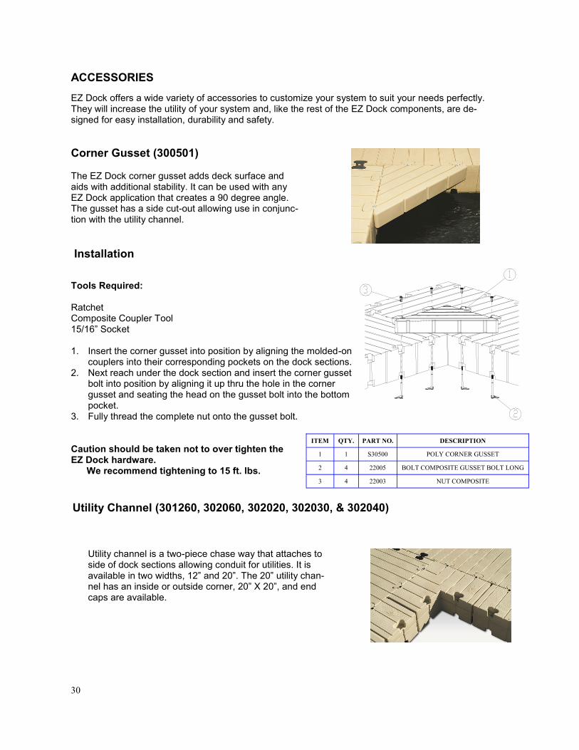
EZ Dock offers a wide variety of accessories to customize your system to suit your needs perfectly. They will increase the utility of your system and, like the rest of the EZ Dock components, are de-signed for easy installation, durability and safety.
The EZ Dock corner gusset adds deck surface and aids with additional stability. It can be used with any EZ Dock application that creates a 90 degree angle. The gusset has a side cut-out allowing use in conjunc-tion with the utility channel.
Tools Required: Ratchet Composite Coupler Tool 15/16‖ Socket 1. Insert the corner gusset into position by aligning the molded-on
couplers into their corresponding pockets on the dock sections. 2. Next reach under the dock section and insert the corner gusset
bolt into position by aligning it up thru the hole in the corner gusset and seating the head on the gusset bolt into the bottom pocket.
3. Fully thread the complete nut onto the gusset bolt. Caution should be taken not to over tighten the EZ Dock hardware. We recommend tightening to 15 ft. lbs.
Corner Gusset (300501)
Utility Channel (301260, 302060, 302020, 302030, & 302040)
Utility channel is a two-piece chase way that attaches to side of dock sections allowing conduit for utilities. It is available in two widths, 12‖ and 20‖. The 20‖ utility chan-nel has an inside or outside corner, 20‖ X 20‖, and end caps are available.
ACCESSORIES
Installation
ITEM QTY. PART NO. DESCRIPTION
1 1 S30500 POLY CORNER GUSSET
2 4 22005 BOLT COMPOSITE GUSSET BOLT LONG
3 4 22003 NUT COMPOSITE

31
Corner Storage Box (300760)
Roomy storage in a compact design that makes the most of available space without interfering with foot traffic. Utility boxes for complete utility hookups through this box are also available.
Utility Channel Installation
Tools Required: Ratchet 1/2‖ and 15/16‖ Socket Composite Coupler Tool Hammer Utility channels are factory assembled. 1. Remove truss head bolts from pocket area and com-
posite coupler nut from the coupler area. Leave the bolt and washer on bottom.
2. Lift off utility channel top and place in pockets on the side of the dock.
3. Reach under the dock section and insert composite coupler bolt into position by aligning it up thru the hole in the utility channel.
4. Thread composite coupler nut onto bolt, being careful not to over tighten.
Installation
The EZ Dock Corner Dock Box attaches to any 90 degree turn in the dock layout using a total of 4 cou-pler pockets. Position the Corner Dock Box over the water and drop the molded–in half couplers located in the bottom of the dock box into the mating coupler sockets on the dock sections. Firmly push into place and attach using the 4 black composite bolts and nuts (22006 and 22003) included in the dock box. See pg. 32 for installation details. To attach to any other dock or deck the dock box may be drilled and attached using self tapping screws and washers (not included).
ITEM QTY. PART NO. DESCRIPTION
1 1 32006 20” UTILITY CHANNEL TOP
2 1 32009 20” UTILITY CHANNEL BOTTOM
3 3 81530SS BOLT 5/16”-18 X 3” TRUSS SS
4 3 80719SS WASHER 5/16” X 2” SS
5 3 80575SS BOLT 5/16”-18 X 3/4” TRUSS HEAD
6 3 211003 BOLT COMPOSITE BOLT LONG
7 3 22003 NUT COMPOSITE

32
Large Storage Box (300750)
This large storage box attaches easily to an EZ Dock system or traditional dock utilizing galvanized bracket hardware. The storage box comes equipped with corro-sion-free polypropylene hinges and a riveted marine steel grade hasp; for EZ locking capability. It is manu-factured along with docks and other accessories giving you a perfect EZ Dock beige match.
Tools Required: Ratchet 1/2‖ Socket 9/16‖ Socket Phillips Screw Driver 1. Attach 18‖ cable strap (S40037) to left side of box using embedded T-nuts. 2 Turn storage box upside down, center bracket on box and mark hole locations. 3. Drill 1/2‖ holes in box. 4. Insert two bolts on the outer edge of the bracket before placing on dock section. These bolts will need to be in place before attaching bracket at T-nut locations on the side of the dock. With two 5/16-18 truss head bolts (81590SS) and flat washers attach bracket to dock. 5. On the back of the bracket, slide three 3/8-16 X 3/4‖ carriage bolts through bracket and back of box. Place flat washers over carriage bolts and fully thread three 3/8-16 Nylok Hex nuts onto the carriage bolts.
Installation
ITEM QTY. PART NO. DESCRIPTION
1 1 S30761 CORNOR DOCK BOX BOTTOM
2 1 S30762 CORNER DOCK BOX LID
3 2 80560SS BOLT 1/4”-20 X 6” HEX SS
4 1 S30762R STORAGE BIN PE RIGHT
6 1 00877 EZ DOCK REFLECTIVE LOGO SMALL
7 1 S30762L STORAGE BIN PE RIGHT
8 2 110047 NUT 1/4”-20JHEX NYLOK SS
9 4 22006 BOLT COMPOSITE GUSSET BOLT LONG 9-1/4”
10 4 22003 NUT COMPOSITE

33
EZ Dock Swim Ladder (300260)
Tools Required: #4 Phillips Screw Driver 1. Loosely attach two of the polyethylene hardware
connectors (201035) to the lower two attachment points of the ladder using two 3/8-16 X 3-1/2 truss head bolts (80636SS).
2. Place the remaining two polyethylene hardware connectors in the top pockets of the dock where the ladder is attached.
3. Place the ladder into the water and bring the bot-tom two connectors up and into the bottom pockets of the dock.
4. With the bottom connectors fully up and into the bottom pockets, bring the top of the ladder toward the dock and into position over the top connectors. Thread two bolts through the holes in the ladder and into the top connectors.
5. Secure the ladder by fully threading the truss head bolts into both the top and bottom couplers. Care should be taken to not over tighten the bolts which could cause them to strip out the threads in the connectors.
The one piece polyethylene ladder is designed for optimal safety with no exposed hardware and 300 pounds of weight capacity. Slip-resistant textured beige color surface stays cool to the touch in hot weather. To assist with the installation of the ladder, there is a hole on the back side of the ladder. Place this hole under water and allow the ladder to fill about a quarter way full with water.
Installation
ITEM QTY. PART NO. DESCRIPTION
1 1 30260 SWIM LADDER POLY 5 STEP
2 4 201035 LADDER CONNECTOR POLY SS
3 4 80636SS BOLT 3/8”-16 X 3-1/2” TRUSS SS

34
EZ Dock Float Step Ladder (300270)
Installation
Tools Required: 1/2‖ drive Ratchet 1/2‖ & 3/4‖ Socket 1/2‖ & 5/16‖ Open End & Box End Wrench Phillips & Standard Screwdriver Pliers Adjustable Wrenches Hammer Small & Large Pry Bar 1. Decide where ladder is to be installed. Ladder requires 2 coupler pock-
ets. 2. Drop hardware connectors into pockets, EZ Dock logo up. 3. Note: There is a left and right rail. The guide track mount is offset on
the rail. The rails should be installed so the glide track mount is offset to the INSIDE. Insert bottom hook in pocket under connector and rock up into place.
4. Use 5/8-11 X 3‖ bolt to secure rail to dock. Tighten 5. Repeat procedure on other side. 6. Lower ladder over glides as shown. 7. Slide ladder over posts on float. Attach float to bottom of ladder using 4 5/16-18 X 3‖ bolts.
The EZ Dock float step ladder allows safe access to and from your dock or sea wall at any water level. The ladder remains above the water when not in use, keeping your lad-der free of hazardous marine growth and electrolysis.
35
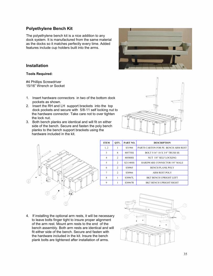
Polyethylene Bench Kit
The polyethylene bench kit is a nice addition to any dock system. It is manufactured from the same material as the docks so it matches perfectly every time. Added features include cup holders built into the arms.
Tools Required: #4 Phillips Screwdriver 15/16‖ Wrench or Socket 1. Insert hardware connectors in two of the bottom dock
pockets as shown. 2. Insert the RH and LH support brackets into the top
dock pockets and secure with 5/8-11 self locking nut to the hardware connector. Take care not to over tighten the lock nut. 3. Both bench planks are identical and will fit on either side of the bench. Secure and fasten the poly bench planks to the bench support brackets using the hardware included in the kit.
Installation
4. If installing the optional arm rests, it will be necessary to leave bolts finger tight to insure proper alignment of the arm rest. Mount arm rests to the end of the bench assembly. Both arm rests are identical and will fit either side of the bench. Secure and fasten with the hardware included in the kit. Insure the bench plank bolts are tightened after installation of arms.
ITEM QTY. PART NO. DESCRIPTION
1, 2 1 S31966 PARTS CARTON FOR PE BENCH ARM REST
3 8 80575SS BOLT 5/16”-18 X 3/4” TRUSS SS
4 2 80580SS NUT 5/8” SELF LOCKING
5 2 S21140SS HARDWARE CONNECTOR 5/8” MALE
6 2 S30965 BENCH PLANK POLY
7 2 S30966 ARM REST POLY
8 1 S30967L BKT BENCH UPRIGHT LEFT
9 1 S30967R BKT BENCH UPRIGHT RIGHT

36
Tools Required: 3/16‖ Allen Wrench 1. Clean out any grit or debris that might have gotten into the
stainless-steel inserts in the dock.
2. Secure each cleat using two (80525SS)15/16-18 X 2-1/2‖ Phillips head machine bolts included in the kit.
12” Galvanized Tie-Up Cleat 300112 10” Aluminum Tie-Up Cleat 300110
These tie-up cleats attach in a pocket on the side of the dock using a hardware connector. This cleat is intended for temporary mooring of boats up to thirty feet long and has the capability of using larger dock line.
Tools Required: Ratchet 15/16‖ Socket Hammer 1. Insert hardware connector into top coupler pocket. 2. Slide hooked portion (S30112) of cleat into bottom pocket
of the dock and bring top portion up and slide over hard-ware connector (S21140SS).
3. Secure bracket to hardware connector with the 5/8‖ lock nut (80580SS). Fully thread nut into place but do not over tighten.
8” Nylon Tie-Up Cleat (300100)
To add to your personal touch and accommodate your personal needs, you may add a 8‖ tie-up cleat to tie up smaller boats. The 8‖ tie-up cleat attaches easily to the heavy duty stainless steel T-nuts molded in pairs around dock section perimeters.
8” Tie-Up Cleat Installation
Installation
ITEM QTY. PART NO. DESCRIPTION
1 1 S30110 CLEAT AL TIE UP 10”
2 1 S21140SS HARDWARE CONNECTOR 5/8” MALE
3 1 80580SS NUT 5/8” SELF LOCKING
ITEM QTY. PART NO. DESCRIPTION
1 1 30101 CLEAT NYLON 8” TIE UP
2 1 80525SS BOLT 5/16”-18 X 2-1/4” CS FLAT SS

37
Bumper Kit (300180)
Dock Edging (400117)
Our dock edging is constructed of durable vinyl to provide a soft cushion to protect boats from the sides of docks and vice versa.
Installation
Tools Required:
#4 Phillips Screwdriver
1. Select the set of T-nuts you want to attach the bumper to. 2. Clean out any grit or debris that might have
gotten into the stainless-steel inserts in the dock.
3. Secure bumper using two flat washers (117005) and 5/16-18 X 1-1/2‖ Phillips Truss head Bolts (80515SS).
ITEM QTY. PART NO. DESCRIPTION
1 1 S30180 BUMPER DOCK
2 2 117005 WASHER 3/8” FLAT SS
3 2 80515SS BOLT 5/16”-18 X 1-1/2” TRUSS SS
ITEM QTY. PART NO. DESCRIPTION
1 1 S40016 DOCK EDGING 10’
2 2 117003 WASHER 5/16” FLAT SS
3 2 80575SS BOLT 5/16”-18 X 3/4” TRUSS SS
This dock bumper is designed to protect your boat . This bumper will attach to the EZ Dock prod-uct using embedded T-nuts.

38
Security Curbing (35116)
The security curbing provides a safe border around dock edges for wheelchairs and attaches in the T-nuts located around the outside perimeter of the dock. Curbing is 116‖ in length, and you will need to cut, fit, and drill holes in the proper locations. Curbing is made from recycled materials.
Tools Required: #4 Phillips Screw Driver 1. Place curbing or vinyl edging on dock section
in area to cover. You may need to cut it to fit. Mark T-nut locations and drill.
2. Using 5/16-18 X 3 flathead Phillips bolt (80530SS) and attach into T-nuts. (Part Num-ber 80530SS is sold separately.)
Installation
Pocket Filler (201030 and 201030-GID) These pocket fillers are used to fill all empty coupler pocket recessions after installation of the dock, an-chorage components, and/or accessories. (Glow-in-the-Dark options are also available). 1. Insert pocket filler into coupler pocket. 2. Press or force pocket filler into the pocket until
it is fully seated. IMPORTANT!!!! All empty coupler pockets must be filled with the pocket filler (201030)
ITEM QTY. PART NO. DESCRIPTION
1 1 N/A DOCK OR PORT SECTION
2 1 201030 KIT POCKET FILLER BEIGE
ITEM QTY. PART NO. DESCRIPTION
1 1 S35116 CURBING 2-1/2” X 3-1/2” X 10’
2 2 80530SS BOLT 5/16”-18 X 3” FLAT SS

39
EZ Dock handrails conform with SOBA and ADA guidelines. Our railing sections are available in a variety of lengths and profiles, and are designed to provide security with minimal ob-struction. You may choose from the standard hot-dipped gal-vanized finish, powder–coated color finish, or our new stainless steel option. Models include accessories for securing fishing rods, and are perfect for residential, resort or park installations. Our railing is also available in aluminum or stainless steel by special order.
Barrier Free Railing Installation
Tools Required: Ratchet 15/16‖ Socket Hammer 1. Loosely attach hardware connectors (with the tapered end
up) to railing legs at the lowest location on the railing. 2. Place hardware connectors in the corresponding top pockets on the dock. 3. Tilting the railing outward and away from the dock at the top, bring the bottom connectors up and into the bottom pockets. 4. When the bottom connectors are fully up and in the bottom
pockets, bring the top of railing back towards the dock so the upper holes in the railing legs fit over the bolts in the hardware connector on the top edge of the dock.
5. Secure the railing by fully tightening the nuts on all hardware connectors using care to not over-tighten the nuts.
Handrails (Galvanized-100910, 100911, 100912, 100913L, 100913R, 100914L, 100914R, 100915, 100916, 100917, 100918, 100919, 100920— Powder Coat Paint-105910, 105911, 105912, 105913L, 105914R, 105915, 105916, 105917, 105918, 105919, & 105920)
ITEM QTY. PART NO. DESCRIPTION
1 1 N/A BARRIER HANDRAILING
2 N/A 80580SS NUT 5/8” SELF LOCKING
3 N/A S21140SS HARDWARE CONNECTOR 5/8” MALE

40
EZ Dock distributors and dealers can provide assistance with:
features and specifications of EZ Dock’s full line of dock products
installation information
use and maintenance procedures
accessory and repair part sales
referrals to local dealers
Maintaining your EZ Dock System Care and Maintenance
Cleaning: Your new EZ Dock Product can be easily cleaned using a brush, mild cleaning agent, and water. For stubborn stains, use a diluted bleach solution. A power washer can be used when convenient. Algae growth at the waterline on the product is normal and will not harm the dock or port section. Ice: EZ Dock floats high enough so that normal ice pressure will not harm the product. However, if the shoreline area has ice pressure pushes wind blown ice, or other ice flows, the dock needs to be removed or disconnected from the moorings. In these circumstances, pipes or piles should be removed to prevent bending due to ice pres-sure.
Customer Service Assistance:
When calling for service assistance, please know the purchase date, model and/or serial code of your components. You will also need your serial number for product registration. This information will help us to better respond to your request. If you need replacement parts, contact your dealer to obtain only genuine parts. These parts will fit right and work correctly because they are made with the same precision used to build your EZ Dock. To locate replace-ment parts in your area, call 1-800-654-8168 (US and Canada), 1-417-235-2223 (Africa, Asia or Central- or South
America), or +46 (0) 380 47 300 in Europe. French speaking residents in Quebec should call 1-800-654-8168. These numbers will put you in contact with your nearest distributor/dealer. You may also locate your nearest distrib-utor or dealer by logging onto our website at www.ez-dock.com.

41
EZ Dock Limited Warranties
Floatation (8 Years) - Modular dock units and EZ Port lifts are warranted against cracks, breakage, leaks, and ultraviolet deterioration caused by defects in material and manufacturing workmanship for a period of eight (8) years from the date of purchase.
Hardware and Accessories (1 Year) - Hardware and accessories are warranted against defects in ma-terial and manufacturing workmanship for a period of one (1) year from the date of purchase.
These Limited Warranties specifically do not cover damages to EZ Dock products caused by: improper installation; use inconsistent with EZ Dock’s instructions and product specifications; vandalism; severe weather and natural disaster; impact by watercraft, ice, falling trees, floating debris, and other foreign objects; animals or aquatic life; unauthorized product modification and attachment; and improper repair.
If an EZ Dock product fails under normal use and within the applicable warranty period, Buyer must sub-mit a written claim to EZ Dock at 878 East Highway 60, Monett, MO 65708 USA. Claims must identify the failed product(s), describe the claimed defect(s), and include copies of dated proofs of pur-chase/receipts from an authorized EZ Dock reseller.
Upon receiving sufficient proof of covered product failure, EZ Dock will, in its sole discretion, either re-pair or replace failed products within a reasonable time after notice, and ship, at Buyer’s expense, re-paired and/or replacement products to the site. ―Repair‖ may be limited to providing a repair kit to Buyer. Costs related to the removal of failed products, and the installation of repaired and/or replaced products shall be at Buyer’s expense.
Warranty periods begin on the date of purchase from an authorized EZ Dock reseller. Repaired and re-placement products are warranted only for the balance of the original limited warranty period. These lim-ited warranties extend only to the original Buyer of products from an authorized EZ Dock reseller (―Original Purchaser‖). Warranties are not transferable to anyone who subsequently purchases products from the Original Purchaser, or to any subsequent purchaser.
In order to ensure proper warranty coverage, Buyer should activate these Limited Warranties by proper-ly registering the purchase of EZ Dock products within thirty (30) days of the date of purchase via the Registration Card provided in EZ Dock’s Owner’s Manual, or by registering online by going to www.ez-dock.com, clicking ―Customer Service‖ and then clicking ―Product Registration‖.
Buyer, by acceptance and use of these limited warranties, waives any rights it would otherwise have to claim or assert that these limited warranties fail of their essential purposes. Buyer agrees that venue for any court action to enforce these limited warranties shall be in Barry or Greene Counties in the State of Missouri. THE FOREGOING LIMITED WARRANTY IS THE SOLE AND EXCLUSIVE WARRANTY FOR SELLER’S
PRODUCTS, AND IS IN LIEU OF ALL OTHER WARRANTIES, EXPRESS OR IMPLIED, IN LAW OR IN FACT.
SELLER SPECIFICALLY DISCLAIMS ALL OTHER WARRANTIES, EXPRESS OR IMPLIED, INCLUDING,
WITHOUT LIMITATION, ALL IMPLIED WARRANTIES OF MERCHANTABILITY AND FITNESS FOR A PAR-
TICULAR USE OR PURPOSE, AND ANY IMPLIED WARRANTIES ARISING OUT OF COURSE OF DEALING
OR PERFORMANCE OR TRADE USAGE. SELLER SHALL NOT BE LIABLE FOR ANY INCIDENTAL, CONSE-
QUENTIAL, EXEMPLARY, SPECIAL, OR PUNITIVE DAMAGES, OR ANY LOSS OF REVENUE, PROFIT OR
USE, ARISING OUT OF A BREACH OF THIS WARRANTY OR IN CONNECTION WITH THE SALE, INSTALLA-
TION, MAINTENANCE, USE, OPERATION OR REPAIR OF ANY PRODUCT. IN NO EVENT WILL SELLER BE
LIABLE FOR ANY AMOUNT GREATER THAN THE PURCHASE PRICE OF A DEFECTIVE PRODUCT.

42
The first dock of its kind...The last dock you will ever need®.
www.ez-dock.com
©2008 EZ Dock, Inc. EZ Dock is a member of the PlayPower family of companies, which also includes Miracle Recreation Equipment company, PlayPower LT Farming-ton, Inc., SoftPlay, L.L.C., HAGS, Aqua Recreation, RSS, Records, and SMP.
DOCKMANUAL-2011