Embed Size (px)
Citation preview

Owners
Manual

2
Table of contents:
1. Cobra Maintenance Schedule 3 2. Belt Drive Maintenance Schedule 4 3. Brake Pad Replacement 5 4. Replacement of GFX & Reverse Bulbs 6 5. R & R Wheel Bearing 7 6. Half shaft Boot Maintenance 9 7. 2010 to current R & R Half shaft 10 8. Prior to 2010 R & R Half shaft 12 9. 2010 to current C.V. Boot Replacement 14
10. Fully Adjustable Shock 17 11. Park Brake Adjustment 18 12. Belt Drive Brake Bleeding 19 13. Cobra Brake Bleeding 20 14. R & R Inline Driveshaft 21 15. Driveshaft Installation 22 16. Rear-end oil change 24 17. Light bar LED Replacement 26 18. Trike in Tow Diagram 27

3
Maintenance Schedule: COBRA Frequency Daily 3,000 4,000 8,000 12,000 16,000 20,000 24,000
Item Brake Pads and Rotors [1] I I I I I I Half Shaft Boots L L L L L L Gear Box Oil [2] R R Wheel Bearings [3] I I I I I I Rear End Oil [4] R R Wheels and Tires I I I I I I All Lighting I Tire Pressure I Brake fluid I I R I I R PWR TRAK Head Bearings T T T
I: Inspect and clean, adjust, lubricate, and/or replace if necessary. R: Replace L: Lubricate with Silicone Spray REAR TIRE PRESSURE 28 PSI T: Torque of Head Bearings (top nut 80 ft.-lbs. adjuster nut 30 ft.-lbs.) This Schedule is in addition to the Honda Maintenance Schedule NOTE: [1] Minimum pad thickness is .04 inches (1.02mm) [2] Gear Case oil should be changed after the first 3 months or 3,000mi., whichever comes first. Gear Case oil should then be changed every 12 months or 20,000mi. Use only NON-synthetic 80W-90 GL-5 gear oil. The Gear Case should contain 6 oz. [3] Wheel bearing torque 200 FT. - LBS. [4] Rear end oil should be changed after the first 3 months or 3,000mi., whichever comes first. Rear end oil should then be changed every 12 months or 20,000mi. Use only NON-synthetic 80W-90 GL-5 gear oil. The differential case should contain no more than 1 qt of gear oil. At higher odometer readings, repeat at frequency intervals established here.

4
Maintenance Schedule: BELT DRIVE Frequency (miles) Daily 4k 8k 12k 16k 20k 24k
Item Belts I I I I I T I Brake Pads and Rotors [1] I I I I I I Half Shaft Boots L L L L L L Wheel Bearings [2] I I I I I I Wheels and Tires I I I I I I All Lighting I Tire Pressure [3] I Brake fluid I I R I I R
I: Inspect: clean, lubricate, and/or replace as necessary. R: Replace L: Lubricate with Silicone Spray T: Tension NOTE: [1] Minimum pad thickness is 0.04 inches (1.02mm) [2] Wheel bearing torque 200 FT.-LBS. [3] Rear tire pressure 28 PSI
At higher odometer readings, repeat at frequency intervals established here. Note: This Schedule is in addition to the Manufacture Maintenance Schedule NOTICE: The remote door opener installed on this unit has a very small electrical draw on your motorcycle battery. If your trike will be unridden for more than 2 weeks you should remove the 15 amp fuse from the red fuse holder located under your seat or right side cover. Another option is using a battery tender.

5
Brake Pad Replacement
1. Raise the rear end off the ground and properly support it in a stable position.
2. Remove the rear wheels. 3. Do not remove calipers from brackets. 4. Remove cotter key from brake pad pins. 5. Remove the pins by sliding them out from the
backside. 6. Remove brake pads and replace with new
ones. 7. Reinstall pins and cotter keys. 8. Repeat on other side and replace wheels. 9. Pump rear brake pedals to build up pressure
before riding.

6
Replacement of GFX & Reverse Bulbs
1. Locate rubber socket cover over backside of
reverse/ground effects bulb housing. Remove by pulling it off.
2. Locate the #2 Philips head screws in the center of the housing and remove screw. Remove with black ground wire.
3. Remove bulb, cut white wire. 4. Using a wire connector, connect the white
wire to the new bulb. 5. Reinstall in reverse order and test.

7
R&R Wheel Bearing
Removal of Wheel Bearing:
1. Place the trike on the center stand on a suitable lift.
2. Remove the five lug nuts and the wheel assembly. 3. Remove the two 3/8 – 24 x 1 HHCS and the brake
caliper. 4. Remove the brake rotor. 5. Remove the half shaft nut from the wheel bearing. 6. Remove safety clip from bottom of upright. 7. Tap roll pin threw upright. 8. While pulling downward on the half shaft rotate the
upright upwards and remove the half shaft from the wheel bearing.
9. Support the upright in the upward position. 10. Remove the three 1/2 – 20 x 2 HHCS, three 1/2 –
20 nyloc nuts, and three 1/2 special washers. 11. Remove the wheel bearing assembly.
Installation of the new wheel bearing assembly:
1. Install the new wheel bearing into the upright. 2. Reinstall the three 1/2 –20 x 2 HHCS and special
washers from the inside of the upright into the wheel bearing.
3. Reinstall the three 1/2 – 20 nyloc nuts and torque to specification. Use thread locking agent.
Warning: Ensure that the flats on the nut do not engage the outside diameter of the wheel bearing.
4. Lubricate the splines on the half shaft with suitable multi-purpose grease.

8
5. Slide the male splines into the wheel bearing. 6. Replace the lower a-arm and roll pin w/safety clip. 7. Lubricate the threads on the half shaft with loctite
and tighten the half shaft nut. Torque to 200 ft/lbs.
8. Reinstall the brake rotor. 9. Reinstall the brake caliper.
10. Reinstall the two 3/8 – 24 x 1 HHCS with Loctite applied and torque to specification.
11. Reinstall the wheel assembly. 12. Remove the trike from the lift.
Specifications:
1. Lug Nuts 70 ft/lbs 2. Axle Nut 200 ft/lbs 3. Brake Caliper 30 ft/lbs

9
Half shaft Boot Maintenance
1. Clean and inspect each boot for tears and cracks. 2. Make sure that all boot clamps are secure. 3. Inspect for any rubbing from exhaust pipe or from
any suspension components. 4. Using silicone spray. Spray a liberal amount onto
all boots to keep the rubber material soft and supple.

10
2010 to current R&R Half shaft
Removal of the half shaft:
1. Place the trike onto the center stand on a suitable lift.
2. Remove the rear wheel. 3. Remove the half shaft nut from the wheel bearing. 4. Remove safety clip from bottom of upright. 5. Tap roll pin out threw upright. 6. While pulling downward on the half shaft rotate the
upright upwards and remove the half shaft from the wheel bearing.
7. Support the upright in the upward position. 8. With the bike in gear rotate the half shaft and pull
it outwards to remove from the retaining clip. Sometimes a few small taps from a dead blow hammer is needed to remove the half shaft.
Installing the new half shaft:
1. Lubricate the outside of the half shaft seal area and the splines with suitable multi-purpose grease.
2. With the clip opening pointing upwards, slide the half shaft onto the stub shaft fully engaging the splines.
3. Slide the male splines into the wheel bearing. 4. Replace the lower roll pin and safety clip ensure
clip is fully seated in grove. 5. Lubricate the threads on the half shaft with motor
oil and torque the axle nut to spec. 6. Replace the wheel assembly.

11
7. Remove the bike from the lift. Torque Specifications: 1. Lug nuts 70 ft.- lbs. 2. Axle nut 200 ft.- lbs.

12
Prior to 2010 R&R Half shaft
Removal of the half shaft:
1. Place the trike onto the center stand on a suitable lift.
2. Remove the rear wheel. 3. Remove the half shaft nut from the wheel bearing. 4. Remove the 1/2 – 20 nyloc nut from the bottom of
the upright. 5. Remove the four 1/4 – 20 x 1/2 SHCS from the
upright plate. 6. Remove the upright plate, lower a-arm spacer,
lower a-arm rod end, and another lower a-arm spacer from the upright.
7. While pulling downward on the half shaft rotate the upright upwards and remove the half shaft from the wheel bearing.
8. Support the upright in the upward position. 9. With the bike in gear rotate the half shaft and pull
it outwards to remove from the retaining clip. Sometimes a few small taps from a dead blow hammer is needed to remove the half shaft.
Installing the new half shaft:
1. Lubricate the outside of the half shaft seal area and the splines with suitable multi-purpose grease.
2. With the clip opening pointing upwards, slide the half shaft onto the stub shaft fully engaging the splines.
3. Slide the male splines into the wheel bearing.

13
4. Replace the lower a-arm spacer, lower a-arm rod end, lower a-arm spacer and upright plate.
5. Using loctite 262 replace the four ¼ - 20 x ½ SHCS and tighten.
6. Replace the ½ - 20 nyloc nut and tighten. 7. Install the Half Shaft nut using Locktite. Torque the nut to 200 FT-LBS. 8. Replace the wheel assembly. 9. Remove the bike from the lift.
Torque Specifications:
1. ¼ - 20 x ½ socket head cap screws 9 ft. - lbs. 2. ½ - 20 nyloc nut 45 ft. - lbs. 3. Lug nuts 70 ft. - lbs.

14
2010 to current C.V. Boot Replacement
Removal of the half shaft:
1. Raise the rear end off the ground and properly support it in a stable position.
2. Remove the rear wheel. 3. Remove the half shaft nut from the wheel bearing. 4. Remove the safety clip and roll pin lower control
arm to the upright 5. Pull down on control arm to remove from upright. 6. While pulling downward on the half shaft rotate the
upright upwards and remove the half shaft from the wheel bearing.
7. Support the upright in the upward position. 8. Next remove the half shaft and stub shaft assy.
from the kit. Removal of inner C.V. boot:
1. Cut and remove both the small and large C.V. boot clamps.
2. Clamp the shaft in a vise with the inner C.V. joint pointing upwards.
3. Slide the C.V. boot down the shaft. 4. Remove inner wire retaining ring from the C.V. joint
outer race. 5. Pull the C.V. joint outer race off the tripod joint. 6. Clean the grease from the tripod joint and C.V.
boot, place new grease back into the C.V. joint outer race.

15
7. There is one method of retaining the tripod joint onto the shaft.
A snap ring on top of the tripod joint. 8. Remove the snap ring from the shaft and press the
tripod joint from the shaft noting the top of the tripod joint.
9. Remove the C.V. boot from shaft.
Removal of outer C.V. boot:
1. If you are changing an outer boot you will do it now. First scribe a line on the shaft marking where the boot was. Now lightly lubricate the small end of the outer boot install lining up the mark.
2. Lightly lubricate the small end of the new C.V. boot and slide down the shaft.
3. Replace the tripod joint back onto the shaft with the correct end pointing outwards. Press the tripod joint onto the shaft until fully seated. Replace the snap ring onto the shaft.
4. Ensure the C.V. joint outer race is approximately 1/3 full with Molybdenum-Disulfide grease to properly lubricate the tripod joint.
5. Slide the C.V. joint outer race onto the tripod joint. This may require rolling the C.V. joint outer race around the joint while sliding on.
6. Replace the inner wire-retaining ring into the C.V. joint housing.
7. Clean grease from the groove on the C.V. joint outer race and the key inside the C.V. boot.
8. Slip the C.V. boot onto the C.V. outer race. 9. Using the long C.V. boot clamp, wrap the band
around the joint in the groove. Slide tip of band into the slot in the clamp. Tension the band until a slight

16
distortion in the boot is evident. Fold the band over the clamp and tap the two tabs over the band until completely crimped. Cut the excess band off.
10. Type-A: This shaft has a longer C.V. boot spacing, slide the small end of the boot into the groove of the shaft and clamp as in step 16. Type-B: This shaft has a shorter C.V. boot spacing, measure the gap in between the C.V. boots. This gap should be 2 inches apart. Clamp the C.V. boot as in step 16.
Reinstalling the half shaft:
1. Lubricate the outside of the half shaft seal area and the splines with suitable multi-purpose grease.
2. With the clip opening pointing upwards, slide the half shaft onto the stub shaft fully engaging the splines.
3. Slide the male splines into the wheel bearing. 4. Raise lower control arm in to place install roll and
safety clip ensure clip is fully seated into grove. 5. Lubricate the threads on the half shaft with motor
oil and torque the half shaft nut to 200 ft pds. 6. Replace the wheel assembly. 7. Remove the bike from the lift.
Specifications:
1. Lug nuts 70 Ft. /Lbs. 2. Molybdenum- disulfide grease for C.V. joint
repacking. 3. Axle nut 200 ft-lbs

17
FULLY ADJUSTABLE SHOCK
With one finger, turn clockwise until you feel tension. Loosen set screw and rotate knob counter clockwise to 9:00 o’clock. Retighten set screws and there will be tension at the start of 9:00 o’clock.
Set Screw
Set Screw

18
PARK BRAKE ADJUSTMENT
SINGLE OR DUAL CALIPER
1. With brake handle down, adjust caliper lever on
both sides, with square head bolt so brake pads
barely free-float on the brake rotor. Secure with
lock nut.
2. Test brake calipers and handle to ensure proper
function. The calipers should lock the rotor after 3
to 5 clicks of the handle. Re-adjust as necessary.
If

19
Belt drive trikes
Brake bleeding procedure:
NOTE: if ABS equipped DO NOT use a vacuum bleeder hand bleed only.
1. Using a vacuum bleeder, follow this procedure carefully.
a. Standard Brake Caliper i. Using correct brake fluid, fill Rear Brake
Master Cylinder Reservoir. ii. Bleed the right rear upper bleed valve.
iii. Bleed the left rear upper bleed valve. b. Performance Brake Caliper
i. Using the correct brake fluid fill the Rear Brake Master Cylinder Reservoir.
ii. Bleed the front Right Rear Caliper Bleed Valves.
iii. Bleed the front Left Rear Caliper Bleed Valves.
iv. Bleed the rear Right Rear Caliper Bleed Valves.
v. Bleed the rear Left Rear Caliper Bleed Valves.
2. Hand bleed the system using the above sequence. Until all air is removed from the lines.
3. Allow the bike to set for a minimum of 20 minutes and recheck.
4. If there is excessive pedal travel on the first pump, repeat steps 1 through 4.
5. Top off the Rear Brake Master Cylinder Reservoir with the correct brake fluid. Clean and reinstall the Rear Brake Master Cylinder Reservoir Cover.

20
Cobra trike Brake bleeding procedure:
1. Using a vacuum bleeder, follow this procedure carefully.
a. Left front upper bleed valve. b. Right front lower bleed valve. c. Rear caliper rear bleed valves. d. Anti-dive bleed valve. e. Rear caliper front bleed valves.
2. Hand bleed the system using the above sequence. Until all air is removed from the lines.
3. Allow the bike to set for a minimum of 20 minutes and recheck.
4. If there is excessive pedal travel on the first pump, repeat steps 1 through 3.

21
R&R Inline Driveshaft
1. Place trike on center stand. 2. Remove rear wheels. 3. Remove the 4 collar stop bolts and remove collar
stop. 4. Remove the 3 bolts from the intermediate shaft. 5. Take a pry bar between the intermediate shaft and
rubber coupler and apply pressure to compress the shaft away from rubber coupler. Remove driveshaft from trike.
6. Inspect splines for wear. 7. Apply moly 52 grease to both ends of driveshaft
and intermediate shaft. 8. Reinstall in reverse order.
Specifications:
4. Lug Nuts 70 ft/lbs 5. Intermediate shaft bolts 45 ft/lbs

22
Driveshaft Installation
Lubricate the output shaft splines.
WARNING: Do not clamp the drive shaft in a vise without a set of rubber or urethane soft jaws. 1. Pack the Rzeppa cross groove joint on the drive
shaft with the provided grease until flush with both sides.
2. Using the provided silicone, lay a bead approximately 3/16 in width around the Rzeppa cross groove joint’s diameter and holes on both sides. Also, lay a small bead around the Rzeppa cross groove joint adapter’s counter bore. Note: Allow the silicone to cure for a MINIMUM of 3 hours before operating the drivetrain.
3. Slide the spring onto the drive shaft. 4. Lubricate the splines on the drive shaft. 5. Tap the slip yoke onto the mating drive shaft
splines until the spring slightly compresses. 6. Align the splines of the slip yoke and output shaft
and slide on the assembled driveshaft. 7. Swing the Rzeppa cross groove joint into place.
WARNING: Do not put excessive pressure onto the Delrin disk when installing the drive shaft.
8. Make sure the heel of the drive shaft rests on the Delrin disk.
9. Align the clearance holes in the Rzeppa cross groove joint with the bolt holes in the Rzeppa cross groove joint adapter.
10. Install six 5/16-18 x 1 ¾ SHCS into the Rzeppa cross groove joint adapter bolt holes. Torque to specification with thread locking compound.

23
Note: Re-torque the six 5/16–18 x 1 ¾ SHCS after the first 100 miles. 11. Make sure the front surface of the yoke is in full
contact with the output shaft flange and the Rzeppa cross groove joint boot is secured BELOW THE FIRST retaining groove on the driveshaft.
Specifications:
1. Lug Nuts 70 ft/lbs 2. Driveshaft Bolts 18 ft/lbs

24
Rear-end oil change
1. Place the trike onto the center stand on a suitable lift.
2. Remove left rear wheel and support trike. 3. Drain rear-end oil from both gear case &
differential see diagram for drain plug locations. 4. Remove both the check level and the fill plug on
gear case 5. Remove the fill plug on rear differential 6. Install both drain plugs. 7. Refill with 80/90 GL5 rated oil (non-synthetic) 8. See diagram for oil amount do not over fill. 9. Replace gear case check level plug hand tighten
only. 10. Replace both differential & gear case fill plugs. 11. Replace wheel. 12. Remove from center stand and enjoy the ride.
Specifications:
1. Differential drain plug 22 ft-lbs. 2. Rear wheels 70 ft-lbs. 3. Both differential and gear case fill plugs 22ft-lbs. 4. Gear case drain and check level plugs hand tighten
only.

25
26
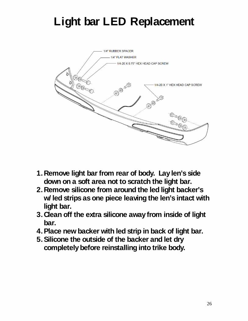
Light bar LED Replacement
1. Remove light bar from rear of body. Lay len’s side down on a soft area not to scratch the light bar.
2. Remove silicone from around the led light backer’s w/led strips as one piece leaving the len’s intact with light bar.
3. Clean off the extra silicone away from inside of light bar.
4. Place new backer with led strip in back of light bar. 5. Silicone the outside of the backer and let dry
completely before reinstalling into trike body.

27
Notice to all owners.
If you plan on trailering your trike, please use this diagram for proper tie down procedure. Failure to do so my result in damage to the trike shock and/or suspension components. When strapping down your trike please hook your tie downs on the inside of your lower control arms. Then cross them for a more security. Chose a strong point in the front such as the lower frame tube, engine guard, or lower triple clamp. Securing your trike in this manner will compress the suspension so it does not bounce around with the trailer. This will greatly limit the movement of your trike when it is in tow.
From all of us at California Sidecar. Enjoy the Ride.