Embed Size (px)
Citation preview
Page 1 Version 4
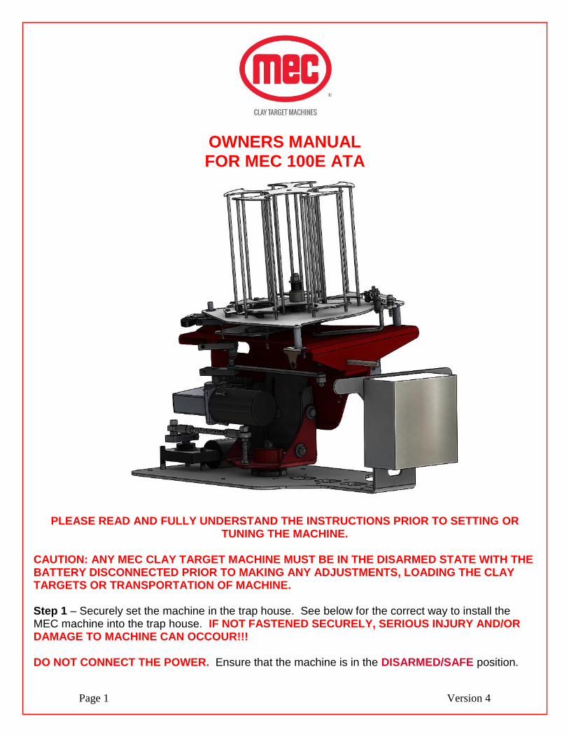
OWNERS MANUAL FOR MEC 100E ATA
PLEASE READ AND FULLY UNDERSTAND THE INSTRUCTIONS PRIOR TO SETTING OR
TUNING THE MACHINE. CAUTION: ANY MEC CLAY TARGET MACHINE MUST BE IN THE DISARMED STATE WITH THE BATTERY DISCONNECTED PRIOR TO MAKING ANY ADJUSTMENTS, LOADING THE CLAY TARGETS OR TRANSPORTATION OF MACHINE. Step 1 – Securely set the machine in the trap house. See below for the correct way to install the MEC machine into the trap house. IF NOT FASTENED SECURELY, SERIOUS INJURY AND/OR DAMAGE TO MACHINE CAN OCCOUR!!! DO NOT CONNECT THE POWER. Ensure that the machine is in the DISARMED/SAFE position.
Page 2 Version 4
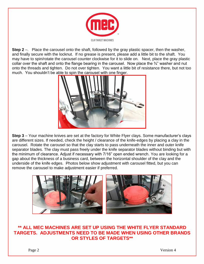
Step 2 –. Place the carousel onto the shaft, followed by the gray plastic spacer, then the washer, and finally secure with the locknut. If no grease is present, please add a little bit to the shaft. You may have to spin/rotate the carousel counter clockwise for it to slide on. Next, place the gray plastic collar over the shaft and onto the flange bearing in the carousel. Now place the ¾” washer and nut onto the threads and tighten. Do not over tighten. You want a little bit of resistance there, but not too much. You shouldn’t be able to spin the carousel with one finger.
Step 3 – Your machine knives are set at the factory for White Flyer clays. Some manufacturer’s clays are different sizes. If needed, check the height / clearance of the knife-edges by placing a clay in the carousel. Rotate the carousel so that the clay starts to pass underneath the inner and outer knife separator blades. The clay must pass freely under the knife separator blades without binding but with the minimum of clearance. Adjust if necessary with 7/16” open ended wrench. You are looking for a gap about the thickness of a business card, between the horizontal shoulder of the clay and the underside of the knife edges. Photos below show adjustment with carousel fitted, but you can remove the carousel to make adjustment easier if preferred.
** ALL MEC MACHINES ARE SET UP USING THE WHITE FLYER STANDARD TARGETS. ADJUSTMENTS NEED TO BE MADE WHEN USING OTHER BRANDS
OR STYLES OF TARGETS**
Page 3 Version 4
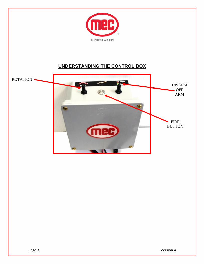
UNDERSTANDING THE CONTROL BOX
DISARM
OFF
ARM
FIRE
BUTTON
ROTATION
Page 4 Version 4
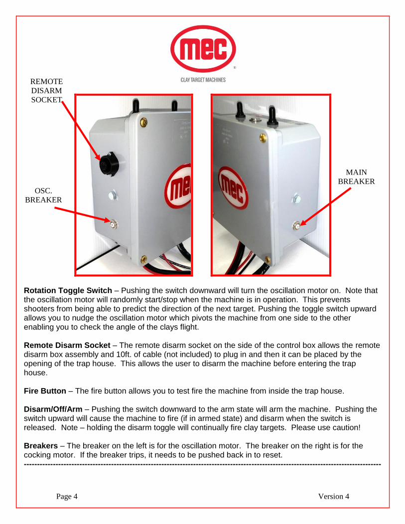
Rotation Toggle Switch – Pushing the switch downward will turn the oscillation motor on. Note that the oscillation motor will randomly start/stop when the machine is in operation. This prevents shooters from being able to predict the direction of the next target. Pushing the toggle switch upward allows you to nudge the oscillation motor which pivots the machine from one side to the other enabling you to check the angle of the clays flight. Remote Disarm Socket – The remote disarm socket on the side of the control box allows the remote disarm box assembly and 10ft. of cable (not included) to plug in and then it can be placed by the opening of the trap house. This allows the user to disarm the machine before entering the trap house. Fire Button – The fire button allows you to test fire the machine from inside the trap house. Disarm/Off/Arm – Pushing the switch downward to the arm state will arm the machine. Pushing the switch upward will cause the machine to fire (if in armed state) and disarm when the switch is released. Note – holding the disarm toggle will continually fire clay targets. Please use caution! Breakers – The breaker on the left is for the oscillation motor. The breaker on the right is for the cocking motor. If the breaker trips, it needs to be pushed back in to reset. ---------------------------------------------------------------------------------------------------------------------------------------
REMOTE
DISARM
SOCKET
OSC.
BREAKER
MAIN
BREAKER
Page 5 Version 4
Step 4 – Check that the ARM/OFF/DISARM switch on the electrical box is in the OFF position. Step 5 – Visually check, from the rear of the machine, that the motion of the Throwing Arm is not restricted or blocked in any way.
CAUTION: ALWAYS OPERATE THE MACHINE FROM BEHIND, NEVER FROM THE FRONT OR THE SIDES OF THE MACHINE. KEEP HANDS AND BODY PARTS AWAY FROM THE MACHINE WHEN ARMING, RELEASING AND DISARMING. Step 6 – Standing at arm’s length behind the machine and making sure that all body parts are clear of the machine, push the ARM/OFF/DISARM toggle switch into the DISARM position and then release it as soon as the throwing arm fires. The toggle switch is spring loaded and will return to the off position as soon as the switch is released, stopping the machine from re-arming itself. If done correctly the arm will be pointing away from the left side of the machine when viewed from behind. Disconnect the power supply to ensure that the machine is not accidentally armed while adjusting and loading the machine. Step 7 – Place a couple of clays in each of the carousel columns, for the purpose of testing the clay flight and trajectory.
Page 6 Version 4
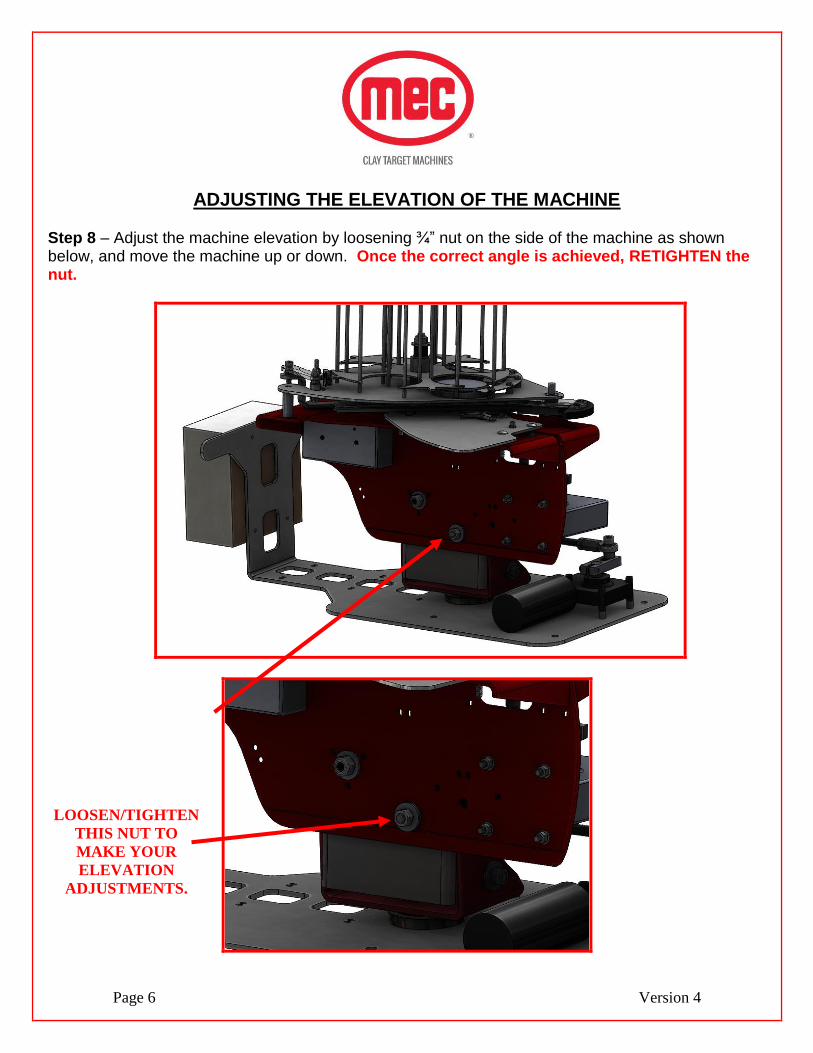
ADJUSTING THE ELEVATION OF THE MACHINE Step 8 – Adjust the machine elevation by loosening ¾” nut on the side of the machine as shown below, and move the machine up or down. Once the correct angle is achieved, RETIGHTEN the nut.
LOOSEN/TIGHTEN
THIS NUT TO
MAKE YOUR
ELEVATION
ADJUSTMENTS.
Page 7 Version 4
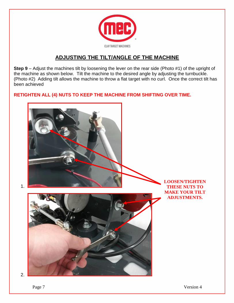
ADJUSTING THE TILT/ANGLE OF THE MACHINE Step 9 – Adjust the machines tilt by loosening the lever on the rear side (Photo #1) of the upright of the machine as shown below. Tilt the machine to the desired angle by adjusting the turnbuckle. (Photo #2) Adding tilt allows the machine to throw a flat target with no curl. Once the correct tilt has been achieved RETIGHTEN ALL (4) NUTS TO KEEP THE MACHINE FROM SHIFTING OVER TIME.
1.
2.
LOOSEN/TIGHTEN
THESE NUTS TO
MAKE YOUR TILT
ADJUSTMENTS.
Page 8 Version 4
ADJUSTING THE ROTATION ANGLE
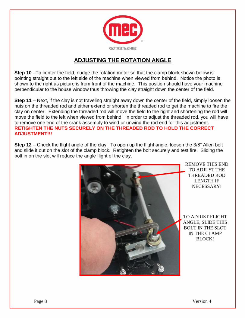
Step 10 –To center the field, nudge the rotation motor so that the clamp block shown below is pointing straight out to the left side of the machine when viewed from behind. Notice the photo is shown to the right as picture is from front of the machine. This position should have your machine perpendicular to the house window thus throwing the clay straight down the center of the field.
Step 11 – Next, if the clay is not traveling straight away down the center of the field, simply loosen the nuts on the threaded rod and either extend or shorten the threaded rod to get the machine to fire the clay on center. Extending the threaded rod will move the field to the right and shortening the rod will move the field to the left when viewed from behind. In order to adjust the threaded rod, you will have to remove one end of the crank assembly to wind or unwind the rod end for this adjustment. RETIGHTEN THE NUTS SECURELY ON THE THREADED ROD TO HOLD THE CORRECT ADJUSTMENT!!!
Step 12 – Check the flight angle of the clay. To open up the flight angle, loosen the 3/8” Allen bolt and slide it out on the slot of the clamp block. Retighten the bolt securely and test fire. Sliding the bolt in on the slot will reduce the angle flight of the clay.
REMOVE THIS END
TO ADJUST THE
THREADED ROD
LENGTH IF
NECESSARY!
TO ADJUST FLIGHT
ANGLE, SLIDE THIS
BOLT IN THE SLOT
IN THE CLAMP
BLOCK!
Page 9 Version 4
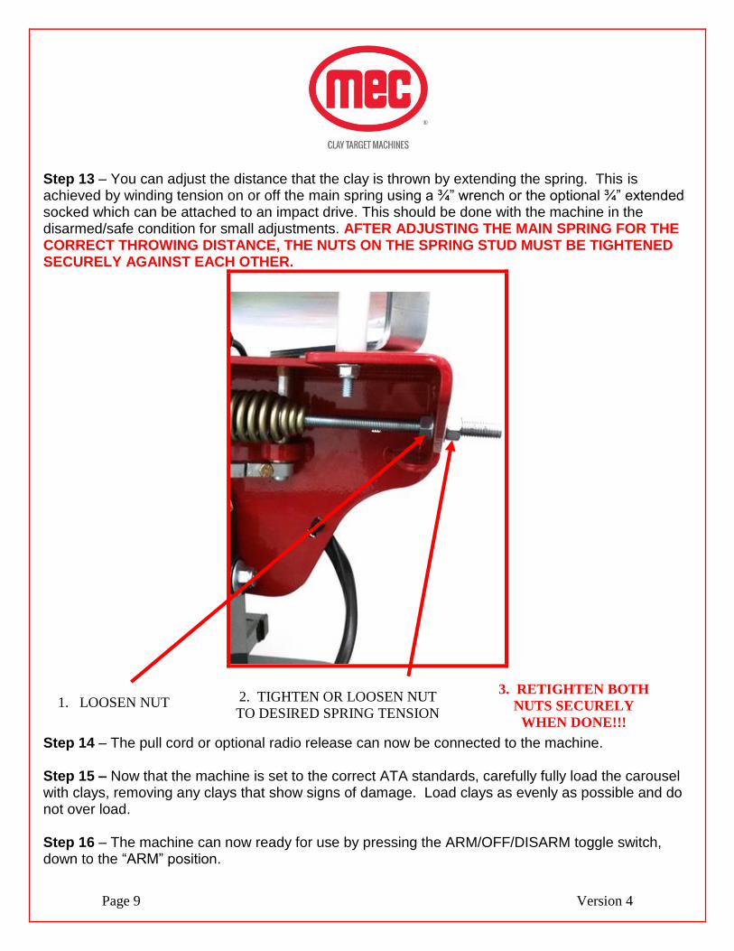
Step 13 – You can adjust the distance that the clay is thrown by extending the spring. This is achieved by winding tension on or off the main spring using a ¾” wrench or the optional ¾” extended socked which can be attached to an impact drive. This should be done with the machine in the disarmed/safe condition for small adjustments. AFTER ADJUSTING THE MAIN SPRING FOR THE CORRECT THROWING DISTANCE, THE NUTS ON THE SPRING STUD MUST BE TIGHTENED SECURELY AGAINST EACH OTHER.
Step 14 – The pull cord or optional radio release can now be connected to the machine. Step 15 – Now that the machine is set to the correct ATA standards, carefully fully load the carousel with clays, removing any clays that show signs of damage. Load clays as evenly as possible and do not over load. Step 16 – The machine can now ready for use by pressing the ARM/OFF/DISARM toggle switch, down to the “ARM” position.
1. LOOSEN NUT 2. TIGHTEN OR LOOSEN NUT
TO DESIRED SPRING TENSION
3. RETIGHTEN BOTH
NUTS SECURELY
WHEN DONE!!!

Page 10 Version 4
Step 17 – Press the fire button on the pull cord or radio release. This will cause the machine to fire a clay target and then reset to the firing position. Pressing the fire button again will do the same as above. Pressing and holding the fire button will continuously fire clays continuously Your machine is now operating smoothly and ready for use. It is critical that you never load or make adjustment to the machine unless it is disarmed, and the power disconnected. While in storage, the machine must be left in the disarmed state and the power/battery disconnected. Any spring tension does not need to be released.
For all ATA rules and guidelines please see the link below.
https://www.shootata.com/Portals/0/pdf/ata_rulebook_web.pdf
Page 11 Version 4
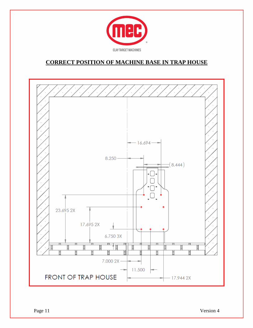
CORRECT POSITION OF MACHINE BASE IN TRAP HOUSE
Page 12 Version 4
FAULT FINDING MECHANICAL
CAUTION: ANY MEC MACHINE MUST BE IN THE DISARMED STATE WITH THE BATTERY
DISCONNECTED PRIOR TO MAKING ANY ADJUSTMENTS, LOADING WITH CLAYS OR
TRANSPORTING
1. The Machine breaks clays - Check loading cycle first: (a) Check that clay in the carousel is intact, not chipped or cracked. If in doubt, remove suspect clays and refill
with ones known to be intact.
(b) With the machine switched “OFF”, rotate the carousel by hand, removing each clay as it drops onto the
throwing plate. Check for cracks and chips. If the clays arrive on the plate intact, then move on to the throwing
section below.
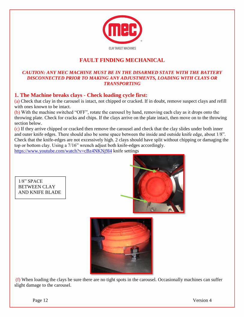
(c) If they arrive chipped or cracked then remove the carousel and check that the clay slides under both inner
and outer knife edges. There should also be some space between the inside and outside knife edge, about 1/8”.
Check that the knife-edges are not excessively high. 2 clays should have split without chipping or damaging the
top or bottom clay. Using a 7/16” wrench adjust both knife-edges accordingly.
https://www.youtube.com/watch?v=cBz4NKNj9I4 knife settings
(f) When loading the clays be sure there are no tight spots in the carousel. Occasionally machines can suffer
slight damage to the carousel.
1/8” SPACE
BETWEEN CLAY
AND KNIFE BLADE
Page 13 Version 4
Check throwing cycle next:
(a) Check that the bolt holding the arm to its clamp block is tight.
(b) Check arm for chunks missing from the black arm rubber or any other physical damage to the arm. If
damage has occurred the black arm rubber should be replaced.
(c) Check for damage to the throwing plate, in case it has been dented, bent or burred. Ensure that no screw
heads protrude and that there are no other obstructions to the clay’s path.
(d) Check the height of the arm over the plate across its whole surface to ensure that the clay fits under the black
rubber throwing arm strip with about 1/16” clearance. Any more than this clearance can cause the arm to break
the clay by riding over it. Adjust by raising or lowering the throwing plate with 4- ½” nuts on the plates
adjustment bolts.
2. Machine throws clays but:
(a) The clay barely flies off throwing plate:
Check the height of the arm over the plate across its whole surface to ensure that the clay fits under the
black rubber throwing arm strip with about 1/16” clearance. Any more than this clearance can cause the
arm to break the clay by riding over it. Adjust by raising or lowering the throwing plate with 4- ½” nuts
on the plates adjustment bolts.
https://www.youtube.com/watch?v=qPnQpIMGT7E E-series arm settings
https://www.youtube.com/watch?v=IDGtb62lXj4 XP series arm adjustments
The arm might be bent down or the throwing plate bent up, squeezing the clay between them, the arm or
plate should be replaced or straightened.
(b) The clay goes no distance (even though the main spring is wound up tight).
The arm is probably bent upwards causing clay to go under it at its tip. This will also cause clays to
break, the solution, is to straighten or replace the arm.
(c) The clays are inconsistent in direction.
This could be caused by buildup of debris on the throwing plate; dirt, leaves, pieces of broken clay.
This is could also be caused by the front rail not moving freely. Light oil or a mechanical adjust if not
free.
(d) If the machine is a “Midi” or Mini”, the arm timing could have slipped.
Page 14 Version 4
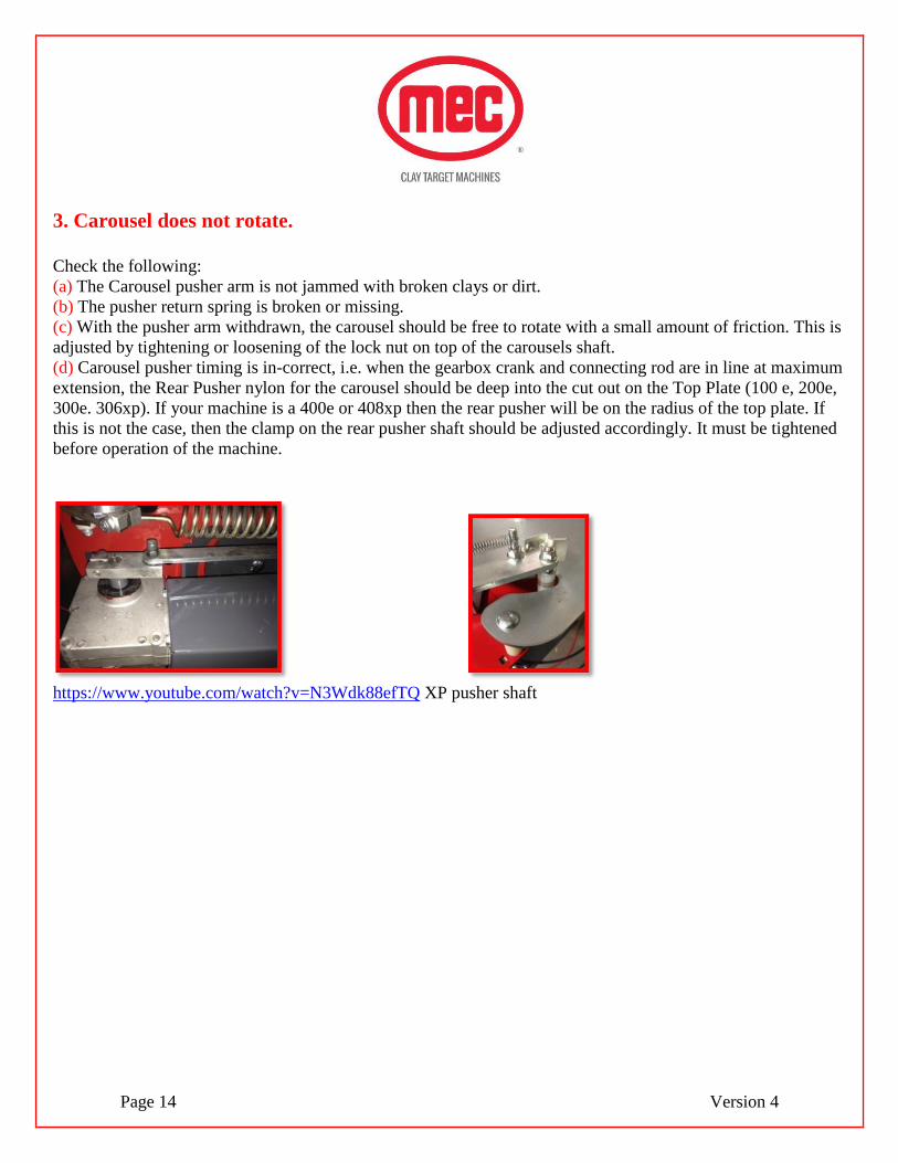
3. Carousel does not rotate.
Check the following:
(a) The Carousel pusher arm is not jammed with broken clays or dirt.
(b) The pusher return spring is broken or missing.
(c) With the pusher arm withdrawn, the carousel should be free to rotate with a small amount of friction. This is
adjusted by tightening or loosening of the lock nut on top of the carousels shaft.
(d) Carousel pusher timing is in-correct, i.e. when the gearbox crank and connecting rod are in line at maximum
extension, the Rear Pusher nylon for the carousel should be deep into the cut out on the Top Plate (100 e, 200e,
300e. 306xp). If your machine is a 400e or 408xp then the rear pusher will be on the radius of the top plate. If
this is not the case, then the clamp on the rear pusher shaft should be adjusted accordingly. It must be tightened
before operation of the machine.
https://www.youtube.com/watch?v=N3Wdk88efTQ XP pusher shaft
Page 15 Version 4
FAULT FINDING ELECTRICAL
CAUTION: ANY MEC MACHINE MUST BE IN THE DISARMED STATE WITH THE BATTERY
DISCONNECTED PRIOR TO MAKING ANY ADJUSTMENTS, LOADING WITH CLAYS OR
TRANSPORTING
1. Machine does not Arm
Check:
(a) Battery is charged and that connections are tight.
(b) Toggle switch is in the down ON position or on the Handheld that the “ARM” indicator light is on.
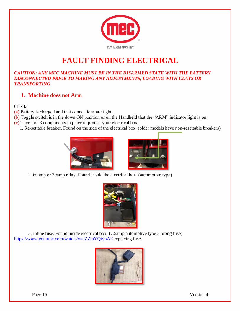
(c) There are 3 components in place to protect your electrical box.
1. Re-settable breaker. Found on the side of the electrical box. (older models have non-resettable breakers)
2. 60amp or 70amp relay. Found inside the electrical box. (automotive type)
3. Inline fuse. Found inside electrical box. (7.5amp automotive type 2 prong fuse)
https://www.youtube.com/watch?v=JZZmYQtybAE replacing fuse
Page 16 Version 4
(b) Check the above items.
(c) If your machine has a Gray Arm / Dis-arm box. Make sure the wires inside are in good shape, free of
corrosion and not pinched on the bottom of the box. Green to White would by-pass the switch and arm the
machine. This would indicate a faulty switch.
3. Machine runs in DISARM position, but not in the ARM position. (a) Check for faulty relay.
4. Machine ARMS but will not fire on the Pull Cord button. (a) Either the connections, cable or command push button are faulty. Disconnect the 110V Plug from the Pull
Cord, using a lead wire, with 1” stripped of each end, insert into the Positive and Negative sides of the outlet
plug. Once contact is made, the machine should fire.
If the trap does not fire, then there is a broken wire in the cable or a bad connection in the three-pin plug
or control box.
(b) If the trap does fire then reconnect the Pull Cord, remove the cover on the push button box and short across
the two spade connectors.
If the trap fires - then the push button is faulty.
If the trap does not fire - then there is a broken wire in the Pull Cord or a bad connection in the three-pin
plug.
5. Trap fires by itself. (a) Disconnect the Pull Cord and switch the trap back on.
If the trap cocks normally - then the Pull Cord is damaged or shorted out. Alternatively, the push button
switch is stuck in or faulty.
(b) If the trap continues to fire – Check to make sure the Throwing arm is contacting the roller limit switch arm.
The arm should pass over the limit switch with only a small amount of space.
(c) If the machine still fires by itself - check if the relay contacts have stuck together, and if so replace. If the
relay operates correctly, but the trap still fires by itself, then the roller limit switch is faulty and should be
replaced.
(d) If the machine still fires by itself – Throwing arm timing could have slipped. Call the Technical Support
Line for help.

Page 17 Version 4
CUSTOMER SERVICE
We're here and ready to help you! Don't forget to take advantage of our trouble shooting guide, website videos, and online owner's manuals, which are available 24/7. You may contact factory customer service at:
MEC Outdoors 800 Horicon Street, Suite 1 Mayville, WI 53050 USA
1-800-797-4632
MEC OUTDOORS Website: www.mecoutdoors.com Facebook: www.facebook.com/MECOutdoors/ Instagram: www.instagram.com/mecoutdoors.official/ Twitter: https://twitter.com/MEC_Outdoors YouTube: www.youtube.com/mecoutdoors
Mayville Engineering Company (MEC) Website: www.mecinc.com
Thanks for choosing MEC! Every machine is hand set and tested prior to leaving our shop to ensure quality. We take pride in our products, so you can have a better experience in the field. Your patronage is very much appreciated! For any questions regarding setup or use of any MEC Clay Target Machines, please give us a call or you can visit us on our website for video footage showing how setup and adjustments are made. To receive our monthly newsletter, go to our website, select the “Shooting Sports Lifestyle” tab and click “Join Us”.