Embed Size (px)
Citation preview
DO NOT INSTALL, OPERATE OR MAINTAIN THIS INSTRUMENT UNLESS YOU HAVE READ AND UNDERSTOOD THIS MANUAL. ONLY COMPETENT PERSONNEL SHOULD INSTALL,
OPERATE OR MAINTAIN THIS INSTRUMENT.
-- UNRESTRICTED --
Copyright © 2012 De Beers All rights reserved. No part of this document may be reproduced, translated, stored in a retrieval system, or transmitted, in any form or by any means, electronic, mechanical, photocopying, recording or otherwise, without prior written permission of the owner.
Note: If this copy is no longer in use, return to sender.
DBT-000750-046 Rev 1.0
De Beers Group Services (Pty) Ltd www.debtech.com
Template Number: DBT-000046-046 Rev 1.1
OWNER’S MANUAL FOR THE
DENSE MEDIUM CONTROLLER
DOCUMENT NO: F01-200000-750
REVISION NO: 1.4
AUTHOR: ARSHAD NABBIE
CREATION DATE: 2012-04-17
DOC TYPE: OWNER’S MANUAL
ABSTRACT
The purpose of this document is to provide technical information to effectively and efficiently install, operate and maintain the Dense Medium Controller (Mark II).
Document Number: F01-200000-750 Revision: 1.4 Page 3 of 52
TABLE OF CONTENTS
SECTION 1: SCOPE OF DOCUMENT ................................................................................................ 4 1.1 Introduction .............................................................................................................................. 4 1.2 Purpose of this Document ........................................................................................................ 4 1.3 Application of this Document .................................................................................................... 4 1.4 Document Conventions ............................................................................................................ 4 1.5 Acronyms, Abbreviations and Definitions ................................................................................. 4 SECTION 2: SETUP AND OPERATION ............................................................................................. 6 2.1 Safety, Health and Environment ............................................................................................... 6 2.2 General Overview..................................................................................................................... 6 2.3 Part Names and Functions ..................................................................................................... 11 2.4 Installation and Wiring ............................................................................................................ 13 2.5 Transducer Switch Setting ...................................................................................................... 20 2.6 Getting Started ....................................................................................................................... 21 SECTION 3: OPERATING PROCEDURES ....................................................................................... 22 3.1 Operational Procedures.......................................................................................................... 22 3.2 Operating Sequences ............................................................................................................. 22 3.3 Home Screen ......................................................................................................................... 22 3.4 Menu Map .............................................................................................................................. 24 3.5 Calibration .............................................................................................................................. 26 3.6 Analog Output ........................................................................................................................ 28 3.7 Serial Output .......................................................................................................................... 30 3.8 On/ Off Controller Output ........................................................................................................ 31 3.9 PID Controller Output ............................................................................................................. 32 3.10 Alarm Beacon ......................................................................................................................... 34 3.11 Advanced Settings ................................................................................................................. 35 3.12 Health and Safety Risks ......................................................................................................... 36 SECTION 4: FIELDBUS .................................................................................................................... 37 4.1 Generic Fieldbus Information ................................................................................................. 37 4.2 Profibus DP ............................................................................................................................ 39 4.3 Ethernet/IP and Modbus/TCP ................................................................................................. 41 SECTION 5: MAINTENANCE............................................................................................................ 45 5.1 Safety Precautions for Maintenance Tasks ............................................................................ 45 5.2 Preventive Maintenance Plan ................................................................................................. 45 5.3 Maintenance Procedures ........................................................................................................ 45 5.4 Spares List ............................................................................................................................. 45 5.5 Controller PCB LED Description ............................................................................................. 47 5.6 Alarm Description and Diagnostics ......................................................................................... 48 SECTION 6: REFERENCES.............................................................................................................. 51 APPENDIX A : WIRING DIAGRAM ................................................................................................ 52
Document Number: F01-200000-750 Revision: 1.4 Page 4 of 52
SECTION 1: SCOPE OF DOCUMENT
1.1 Introduction
The Dense Medium Controller (DMC) is an instrument that measures the density of the ferro-magnetic slurry in Dense Medium Separation (DMS) plants as used in various mining sectors. However, unlike most densitometers, the DMC is a non-nuclear instrument. The owner’s manual contains information for the installation, operation and troubleshooting of the DMC.
1.2 Purpose of this Document
The purpose of this document is to provide technical information and operating instructions required to effectively and efficiently install, operate and maintain the DMC.
1.3 Application of this Document
This document applies to the Mark II version of the DMC, as redesigned and launched in the year 2011. This document applies to all seven sizes of the DMC Transducer viz. 50mm, 75mm, 110mm, 160mm, 225mm, 315mm and 355mm. This document also describes the DMC Controller unit.
1.4 Document Conventions
MENU - text in this font represents the LCD display of the DMC Controller. xxx - represents any valid value or text.
<Info> - current information is displayed within these brackets.
The terms ‘earthing’ and ‘grounding’ can be used interchangeably in this document.
1.5 Acronyms, Abbreviations and Definitions
Term Term Description / Definition 3CR12 A type of ferritic utility stainless steel.
a.k.a. also known as
CSA Canadian Standards Association
csv Comma separated variable
DMC Dense Medium Controller
DMS Dense Medium Separation
EMC Electro Magnetic Compatibility
Ethernet/IP Ethernet industrial protocol
FeSi Ferrosilicon
ftp File Transfer Protocol GSD General Station Description kg Kilogram, unit of mass measurement. HDPE High Density Polyethylene HMS Heavy Medium Separation html Hyper-text mark-up language IP Ingress Protection m Metre, unit of distance measurement. lb Pounds, unit of mass measurement. LCD Liquid Crystal Display
Document Number: F01-200000-750 Revision: 1.4 Page 5 of 52
MCC Motor Control Centre mm Millimetres, unit of distance measurement. PCB Printed Circuit Board PID Proportional Integral Derivative, referring to an industrial control system. PLC Programmable Logic Controller Profibus DP Process field bus decentralised peripherals RS232 A standard serial communication protocol. SABS South African Bureau of Standards SANS South African National Standard SAP An enterprise management software product. S.G. Specific Gravity shtm Server side html SSI Server Side Include UPS Uninterruptable power supply
Profibus, Profibus DP, ProfiNet, CANopen, DeviceNet, EtherNet, Ethernet/IP and ModBus are registered trademarks and belong to their respective owners. The Phoenix Contact Profibus connector image is the property of Phoenix Contact GmbH & Co. KG. and is used here for illustrative purposes only.
Document Number: F01-200000-750 Revision: 1.4 Page 6 of 52
SECTION 2: SETUP AND OPERATION
2.1 Safety, Health and Environment
The DMC is supplied with 85-264VAC power for its operation and, as such, appropriate precautions must be taken when operating and / or maintaining the unit in terms of local safety procedures and regulations as well as national legislation. The DMC Transducer has a mass of up to 150kg [331 lb], appropriate lifting equipment and personal protective equipment must be used. Within the Transducer’s enclosure for its electronics is a heater plate that regulates the temperature of the electronics. This plate can be hot to the touch and can reach temperatures of 80 oC [176 oF]. Caution must be exercised when handling this plate.
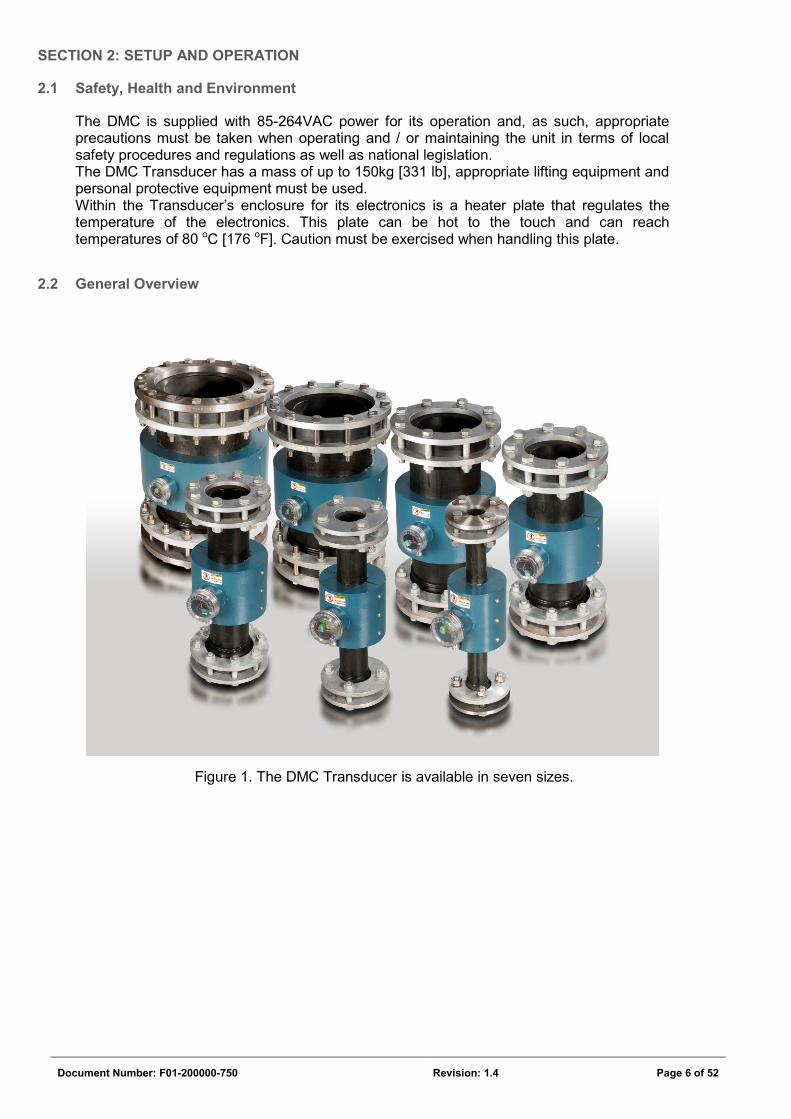
2.2 General Overview
Figure 1. The DMC Transducer is available in seven sizes.
Document Number: F01-200000-750 Revision: 1.4 Page 7 of 52
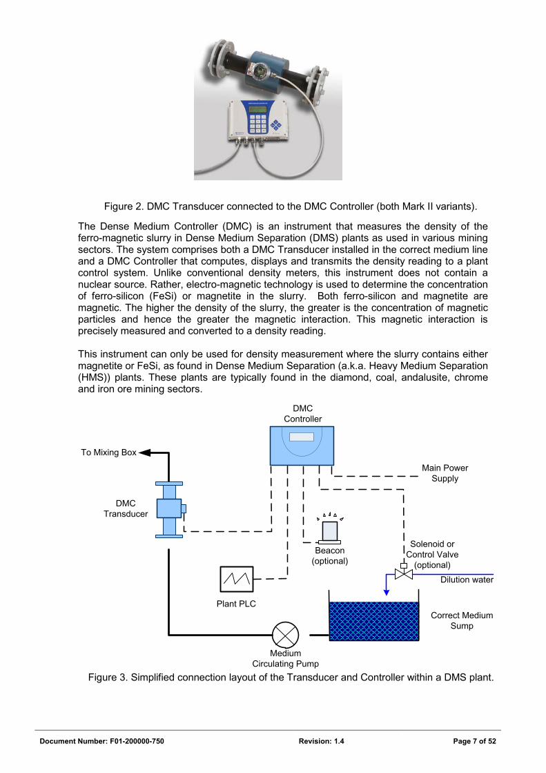
Figure 2. DMC Transducer connected to the DMC Controller (both Mark II variants).
The Dense Medium Controller (DMC) is an instrument that measures the density of the ferro-magnetic slurry in Dense Medium Separation (DMS) plants as used in various mining sectors. The system comprises both a DMC Transducer installed in the correct medium line and a DMC Controller that computes, displays and transmits the density reading to a plant control system. Unlike conventional density meters, this instrument does not contain a nuclear source. Rather, electro-magnetic technology is used to determine the concentration of ferro-silicon (FeSi) or magnetite in the slurry. Both ferro-silicon and magnetite are magnetic. The higher the density of the slurry, the greater is the concentration of magnetic particles and hence the greater the magnetic interaction. This magnetic interaction is precisely measured and converted to a density reading. This instrument can only be used for density measurement where the slurry contains either magnetite or FeSi, as found in Dense Medium Separation (a.k.a. Heavy Medium Separation (HMS)) plants. These plants are typically found in the diamond, coal, andalusite, chrome and iron ore mining sectors.
Figure 3. Simplified connection layout of the Transducer and Controller within a DMS plant.
Solenoid or Control Valve
(optional)
Beacon (optional)
Medium Circulating Pump
Plant PLC
To Mixing Box
Correct Medium Sump
Main Power Supply
DMC Controller
DMC Transducer
Dilution water
Document Number: F01-200000-750 Revision: 1.4 Page 8 of 52
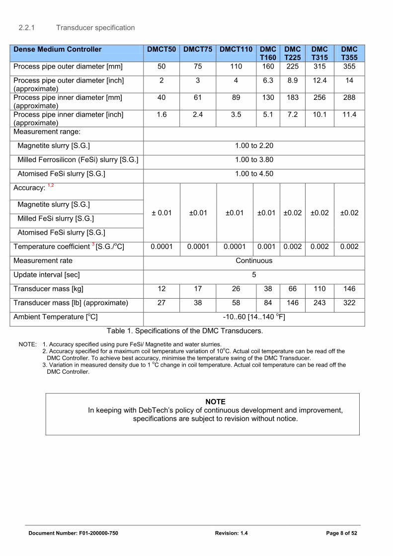
2.2.1 Transducer specification
Table 1. Specifications of the DMC Transducers.
NOTE: 1. Accuracy specified using pure FeSi/ Magnetite and water slurries. 2. Accuracy specified for a maximum coil temperature variation of 10oC. Actual coil temperature can be read off the
DMC Controller. To achieve best accuracy, minimise the temperature swing of the DMC Transducer. 3. Variation in measured density due to 1 oC change in coil temperature. Actual coil temperature can be read off the
DMC Controller.
NOTE In keeping with DebTech’s policy of continuous development and improvement,
specifications are subject to revision without notice.
Dense Medium Controller DMCT50 DMCT75 DMCT110 DMC T160
DMC T225
DMC T315
DMC T355
Process pipe outer diameter [mm] 50 75 110 160 225 315 355
Process pipe outer diameter [inch] (approximate)
2 3 4 6.3 8.9 12.4 14
Process pipe inner diameter [mm] (approximate)
40 61 89 130 183 256 288
Process pipe inner diameter [inch] (approximate)
1.6 2.4 3.5 5.1 7.2 10.1 11.4
Measurement range:
Magnetite slurry [S.G.] 1.00 to 2.20
Milled Ferrosilicon (FeSi) slurry [S.G.] 1.00 to 3.80
Atomised FeSi slurry [S.G.] 1.00 to 4.50
Accuracy: 1,2
± 0.01 ±0.01 ±0.01 ±0.01 ±0.02 ±0.02 ±0.02 Magnetite slurry [S.G.]
Milled FeSi slurry [S.G.]
Atomised FeSi slurry [S.G.]
Temperature coefficient 3 [S.G./oC] 0.0001 0.0001 0.0001 0.001 0.002 0.002 0.002
Measurement rate Continuous
Update interval [sec] 5
Transducer mass [kg] 12 17 26 38 66 110 146
Transducer mass [lb] (approximate) 27 38 58 84 146 243 322
Ambient Temperature [oC] -10..60 [14..140 oF]
Document Number: F01-200000-750 Revision: 1.4 Page 9 of 52
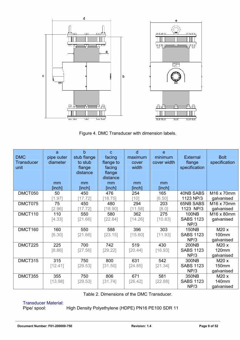
Figure 4. DMC Transducer with dimension labels.
Table 2. Dimensions of the DMC Transducer.
Transducer Material: Pipe/ spool: High Density Polyethylene (HDPE) PN16 PE100 SDR 11
DMC Transducer unit
a pipe outer diameter
mm [inch]
b stub flange
to stub flange
distance
mm [inch]
c facing
flange to facing flange
distance mm
[inch]
d maximum
cover width
mm [inch]
e minimum
cover width
mm [inch]
External flange
specification
Bolt
specification
DMCT050
50 [1.97]
450 [17.72]
476 [18.75]
254 [10]
165 [6.50]
40NB SABS 1123 NP/3
M16 x 70mm galvanised
DMCT075
75 [2.96]
450 [17.72]
480 [18.90]
294 [11.58]
203 [8.0]
65NB SABS 1123 NP/3
M16 x 70mm galvanised
DMCT110
110 [4.33]
550 [21.66]
580 [22.84]
362 [14.26]
275 [10.83]
100NB SABS 1123
NP/3
M16 x 80mm galvanised
DMCT160
160 [6.30]
550 [21.66]
588 [23.15]
396 [15.60]
303 [11.93]
150NB SABS 1123
NP/3
M20 x 100mm
galvanised DMCT225
225
[8.86] 700
[27.56] 742
[29.22] 519
[20.44] 430
[16.93] 200NB
SABS 1123 NP/3
M20 x 120mm
galvanised DMCT315
315
[12.41] 750
[29.53] 800
[31.50] 631
[24.85] 542
[21.34] 300NB
SABS 1123 NP/3
M20 x 150mm
galvanised DMCT355
355
[13.98] 750
[29.53] 806
[31.74] 671
[26.42] 581
[22.88] 350NB
SABS 1123 NP/3
M20 x 140mm
galvanised
Document Number: F01-200000-750 Revision: 1.4 Page 10 of 52
Backing flanges: SABS 1123, used with HDPE stubs. Hot dipped galvanised to SABS 763. Stub flange: Class 10 HDPE/PP Flat face flanges: SABS 1123 Type NP/3, 1000/3, NP 1000kPa, Steel flanges, not galvanised, for
welding onto existing steel pipework, where applicable. Metal body: 3CR12 utility stainless steel, 304/ 316 stainless steel in part. Powder coated,
blue, hammer finish. Transducer degree of protection: IP66, certified by the SABS to SANS 60529:2001
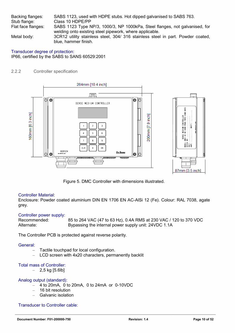
2.2.2 Controller specification
Figure 5. DMC Controller with dimensions illustrated.
Controller Material: Enclosure: Powder coated aluminium DIN EN 1706 EN AC-AlSi 12 (Fe). Colour: RAL 7038, agate grey. Controller power supply: Recommended: 85 to 264 VAC (47 to 63 Hz), 0.4A RMS at 230 VAC / 120 to 370 VDC Alternate: Bypassing the internal power supply unit: 24VDC 1.1A The Controller PCB is protected against reverse polarity. General:
– Tactile touchpad for local configuration. – LCD screen with 4x20 characters, permanently backlit
Total mass of Controller:
– 2,5 kg [5.6lb] Analog output (standard):
– 4 to 20mA, 0 to 20mA, 0 to 24mA or 0-10VDC – 16 bit resolution – Galvanic isolation
Transducer to Controller cable:
Document Number: F01-200000-750 Revision: 1.4 Page 11 of 52
– 6 core, 0.5mm2 screened multi-core cable – 25m cable length supplied, pre-wired at the Transducer end. – CSA approved
Serial interface (standard):
– RS-232, meets EIA-232-E and V.28 specifications – Settings:
• baud rate 9600, 8 data bits, No parity, 1 Stop bit, Hardware flow control.
Fieldbus output (optional): – Currently available: Profibus DP, Ethernet/IP, Modbus/TCP – On request: Profinet, CANopen, DeviceNet
Controller degree of protection: IP65, certified by the SABS to SANS 60529:2001
2.3 Part Names and Functions
The DMC comprise the Transducer and Controller as standard. Optional extra items comprise the Alarm Beacon, Solenoid Valve and Fieldbus plug-in circuit boards.
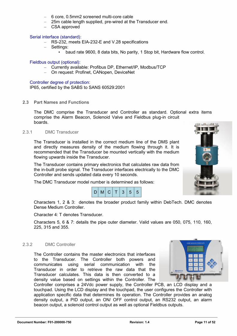
2.3.1 DMC Transducer
The Transducer is installed in the correct medium line of the DMS plant and directly measures density of the medium flowing through it. It is recommended that the Transducer be mounted vertically with the medium flowing upwards inside the Transducer.
The Transducer contains primary electronics that calculates raw data from the in-built probe signal. The Transducer interfaces electrically to the DMC Controller and sends updated data every 10 seconds.
The DMC Transducer model number is determined as follows:
D M C T 3 5 5
Characters 1, 2 & 3: denotes the broader product family within DebTech. DMC denotes Dense Medium Controller.
Character 4: T denotes Transducer.
Characters 5, 6 & 7: details the pipe outer diameter. Valid values are 050, 075, 110, 160, 225, 315 and 355.
2.3.2 DMC Controller
The Controller contains the master electronics that interfaces to the Transducer. The Controller both powers and communicates using serial communication with the Transducer in order to retrieve the raw data that the Transducer calculates. This data is then converted to a density value based on settings within the Controller. The Controller comprises a 24Vdc power supply, the Controller PCB, an LCD display and a touchpad. Using the LCD display and the touchpad, the user configures the Controller with application specific data that determines its operation. The Controller provides an analog density output, a PID output, an ON/ OFF control output, an RS232 output, an alarm beacon output, a solenoid control output as well as optional Fieldbus outputs.
Document Number: F01-200000-750 Revision: 1.4 Page 12 of 52
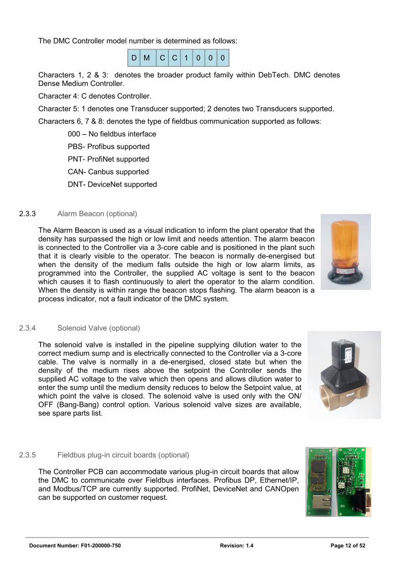
The DMC Controller model number is determined as follows:
D M C C 1 0 0 0
Characters 1, 2 & 3: denotes the broader product family within DebTech. DMC denotes Dense Medium Controller.
Character 4: C denotes Controller.
Character 5: 1 denotes one Transducer supported; 2 denotes two Transducers supported.
Characters 6, 7 & 8: denotes the type of fieldbus communication supported as follows:
000 – No fieldbus interface
PBS- Profibus supported
PNT- ProfiNet supported
CAN- Canbus supported
DNT- DeviceNet supported
2.3.3 Alarm Beacon (optional)
The Alarm Beacon is used as a visual indication to inform the plant operator that the density has surpassed the high or low limit and needs attention. The alarm beacon is connected to the Controller via a 3-core cable and is positioned in the plant such that it is clearly visible to the operator. The beacon is normally de-energised but when the density of the medium falls outside the high or low alarm limits, as programmed into the Controller, the supplied AC voltage is sent to the beacon which causes it to flash continuously to alert the operator to the alarm condition. When the density is within range the beacon stops flashing. The alarm beacon is a process indicator, not a fault indicator of the DMC system.
2.3.4 Solenoid Valve (optional)
The solenoid valve is installed in the pipeline supplying dilution water to the correct medium sump and is electrically connected to the Controller via a 3-core cable. The valve is normally in a de-energised, closed state but when the density of the medium rises above the setpoint the Controller sends the supplied AC voltage to the valve which then opens and allows dilution water to enter the sump until the medium density reduces to below the Setpoint value, at which point the valve is closed. The solenoid valve is used only with the ON/ OFF (Bang-Bang) control option. Various solenoid valve sizes are available, see spare parts list.
2.3.5 Fieldbus plug-in circuit boards (optional)
The Controller PCB can accommodate various plug-in circuit boards that allow the DMC to communicate over Fieldbus interfaces. Profibus DP, Ethernet/IP, and Modbus/TCP are currently supported. ProfiNet, DeviceNet and CANOpen can be supported on customer request.
Document Number: F01-200000-750 Revision: 1.4 Page 13 of 52
2.4 Installation and Wiring
2.4.1 Transducer Installation
2.4.1.1 Mounting
As was shown in Figure 3, the Transducer should be installed in the pipeline between the medium circulating pump and the mixing box. Where the plant has steel pipe work, the steel flanges supplied with the DMC Transducer should be welded to the mating pipe work. Where the plant has HDPE pipe-work, a mating HDPE stub flange (not supplied) must be mated to the plant pipe work. The Transducer must, together with the supplied sealing gaskets, then be bolted in place between these flanges.
The Transducers must be braced in position securely. The weight of the slurry in the pipe-work around the DMC will be significant. The pipe-work on either side of the Transducer must be independently braced from the plant structure such that no load strain is exerted on the Transducer. Do not use the Transducer to close any shortcomings of the pipe-work by forcing the bolts in order to bring the pipe-work together.
IMPORTANT
The following installation requirements are important for the optimum operation of the unit and for accurate density readings:
1. Although the Transducer is designed with adequate electro-magnetic shielding, it may be affected by external magnetic fields such as those generated by large motors, demagnetising coils etc. It is therefore recommended that it be mounted at least 300mm [11.9”] away from such devices.
2. The Transducer must ideally be installed in a vertical pipe and there must be at least 300mm [11.9”] length of pipe before and after the unit which is free of bends or diameter changes. Note: This instrument will function when mounted horizontally, however a full volume of slurry must be ensured to obtain true density readings. When mounted horizontally, the medium must not be allowed to settle inside the instrument. Any settling of medium inside the Transducer will affect the density measurement.
3. The Transducer must be orientated such that the cable exits towards the ground.
4. To minimise the negative effects of temperature on accuracy, do not install the Transducer in direct sunlight. If this is not possible then the housing that contains the Transducer electronics must be rotated away from direct sunlight.
Document Number: F01-200000-750 Revision: 1.4 Page 14 of 52
2.4.1.2 Electrical Connection
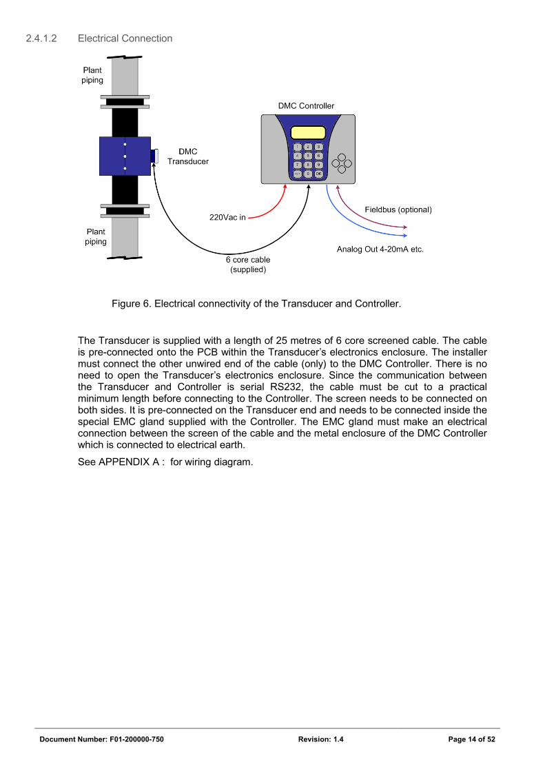
Figure 6. Electrical connectivity of the Transducer and Controller.
The Transducer is supplied with a length of 25 metres of 6 core screened cable. The cable is pre-connected onto the PCB within the Transducer’s electronics enclosure. The installer must connect the other unwired end of the cable (only) to the DMC Controller. There is no need to open the Transducer’s electronics enclosure. Since the communication between the Transducer and Controller is serial RS232, the cable must be cut to a practical minimum length before connecting to the Controller. The screen needs to be connected on both sides. It is pre-connected on the Transducer end and needs to be connected inside the special EMC gland supplied with the Controller. The EMC gland must make an electrical connection between the screen of the cable and the metal enclosure of the DMC Controller which is connected to electrical earth.
See APPENDIX A : for wiring diagram.
Document Number: F01-200000-750 Revision: 1.4 Page 15 of 52
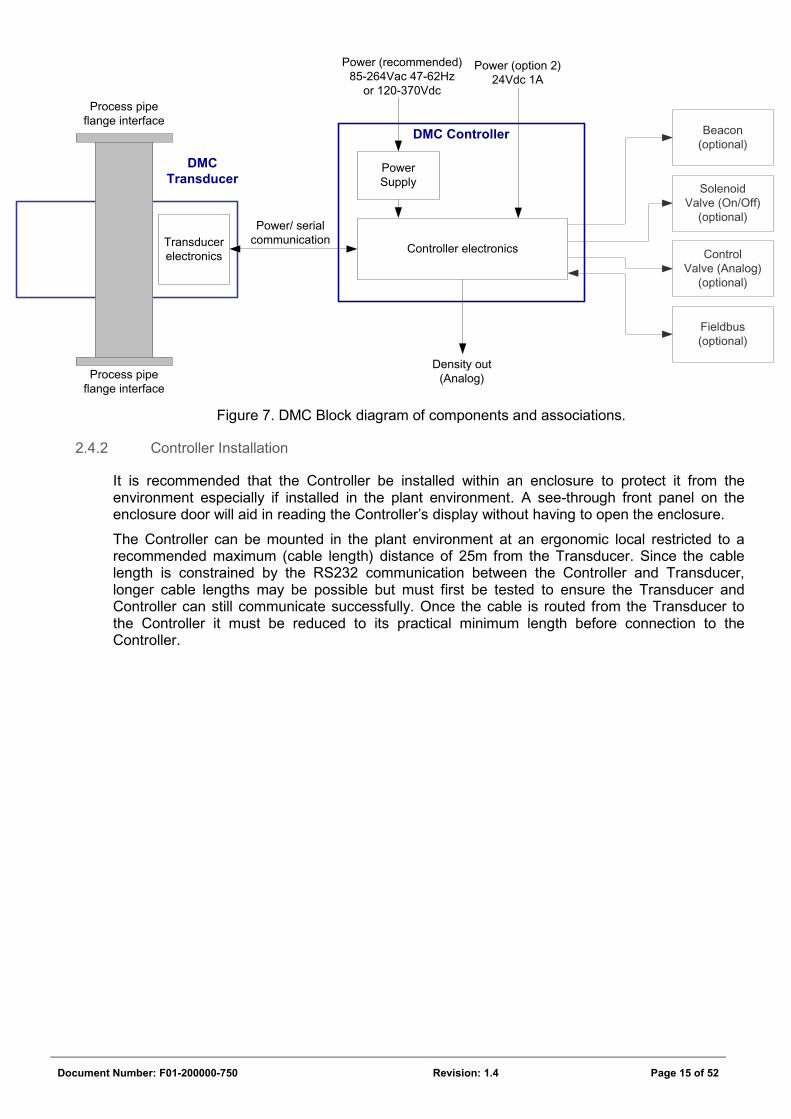
Figure 7. DMC Block diagram of components and associations.
2.4.2 Controller Installation
It is recommended that the Controller be installed within an enclosure to protect it from the environment especially if installed in the plant environment. A see-through front panel on the enclosure door will aid in reading the Controller’s display without having to open the enclosure.
The Controller can be mounted in the plant environment at an ergonomic local restricted to a recommended maximum (cable length) distance of 25m from the Transducer. Since the cable length is constrained by the RS232 communication between the Controller and Transducer, longer cable lengths may be possible but must first be tested to ensure the Transducer and Controller can still communicate successfully. Once the cable is routed from the Transducer to the Controller it must be reduced to its practical minimum length before connection to the Controller.
Transducer electronics
DMCTransducer
DMC Controller
Controller electronics
Power Supply
SolenoidValve (On/Off)
(optional)
Beacon(optional)
Power (recommended) 85-264Vac 47-62Hz
or 120-370Vdc
Power (option 2)24Vdc 1A
Power/ serial communication
Process pipe flange interface
Process pipe flange interface
ControlValve (Analog)
(optional)
Fieldbus (optional)
Density out (Analog)
Document Number: F01-200000-750 Revision: 1.4 Page 16 of 52
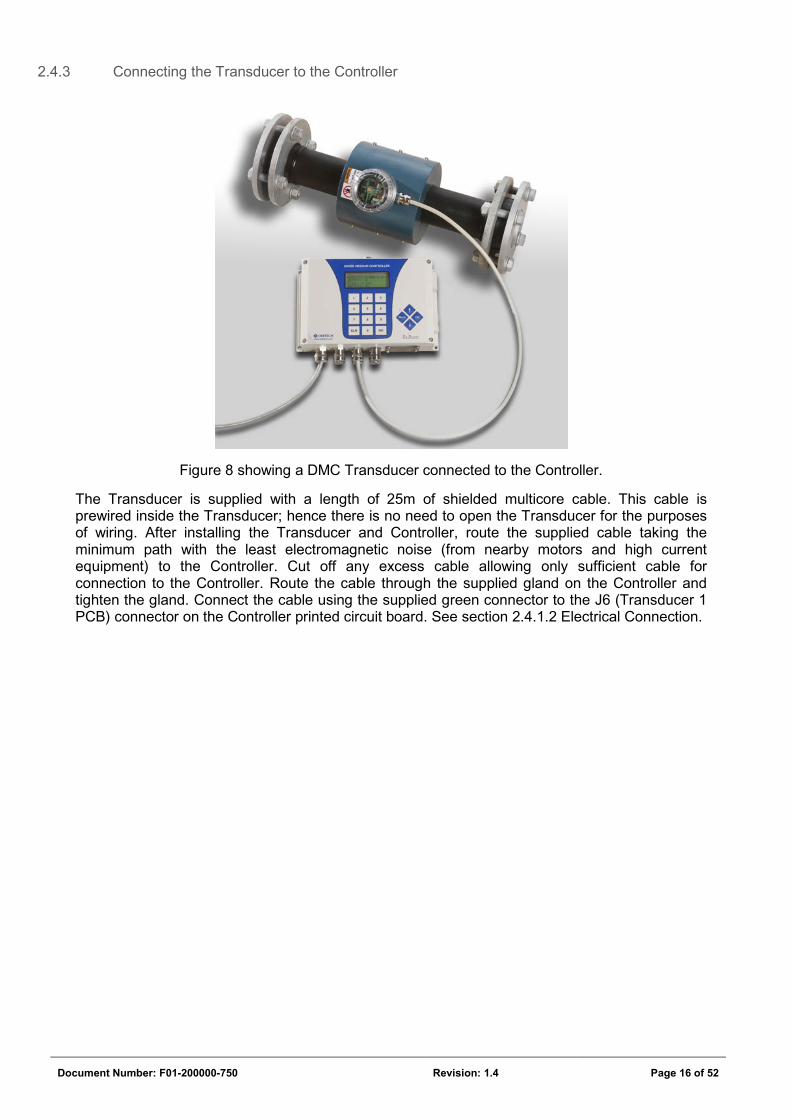
2.4.3 Connecting the Transducer to the Controller
Figure 8 showing a DMC Transducer connected to the Controller.
The Transducer is supplied with a length of 25m of shielded multicore cable. This cable is prewired inside the Transducer; hence there is no need to open the Transducer for the purposes of wiring. After installing the Transducer and Controller, route the supplied cable taking the minimum path with the least electromagnetic noise (from nearby motors and high current equipment) to the Controller. Cut off any excess cable allowing only sufficient cable for connection to the Controller. Route the cable through the supplied gland on the Controller and tighten the gland. Connect the cable using the supplied green connector to the J6 (Transducer 1 PCB) connector on the Controller printed circuit board. See section 2.4.1.2 Electrical Connection.
Document Number: F01-200000-750 Revision: 1.4 Page 17 of 52
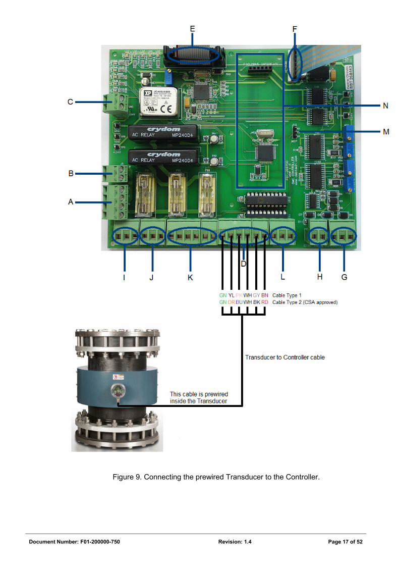
Figure 9. Connecting the prewired Transducer to the Controller.
Document Number: F01-200000-750 Revision: 1.4 Page 18 of 52
CONNECTOR LABEL DESCRIPTION A 220V AC IN (J6) Connect the Mains incoming AC supply (85 – 264VAC)
to this connector. B 220V AC to PSU (J5) The 24Vdc power supply is powered with AC power via
this connector. This connection is factory pre-wired. C +24V IN (J4) 24Vdc is supplied from the power supply to the
Controller PCB via this connector. This connection is factory pre-wired. If an external 24Vdc supply is preferred, connect it directly to this connector.
D Transducer 1 PCB (J9) The Transducer connects to the Controller at this connector. This connection must be made by the end user. Ensure the correct wiring is observed.
E LCD (J10) The LCD screen connects at this connector. This connection is factory pre-wired.
F KEYPAD (J2) The touchpad connects at this connector. The touchpad connector is not keys so if insertion in one direction does not provide the correct respond on the LCD, rotate the connector and insert again. This connection is factory pre-wired.
G ANALOG-OUT (J14) The analog output signal that provides the density value connects here. 4-20mA, 0-20mA, 0-24mA and 0-10Vdc are supported, exclusively.
H CTRL VALVE (J13) This is a 4-20mA PID output to a control valve for automatic water addition (to reduce the density).
I BEACON (J7) The Alarm beacon connects at this connector. The beacon is supplied with an AC signal when the density is outside a set range. The AC signal magnitude corresponds with the Mains AC Voltage supplied to the DMC Controller.
J SOL VALVE (J8) ON/OFF solenoid valve connector for automatic water dilution. The solenoid valve is supplied with an AC signal when the density is above a set value. The AC signal magnitude corresponds with the Mains AC Voltage supplied to the DMC Controller.
K Transducer 2 PCB (J3) Reserved for future use. L RS232 (J11) To obtain the density value on a PC, connect an RS232
client to this connector. M MIF (J12) DebTech developer diagnostic connector.
N FIELDBUS INTERFACE CONNECTOR (J1)
Where selected, a Fieldbus interface PCB plugs in here.
Table 3. Connector layout for the DMC Controller.
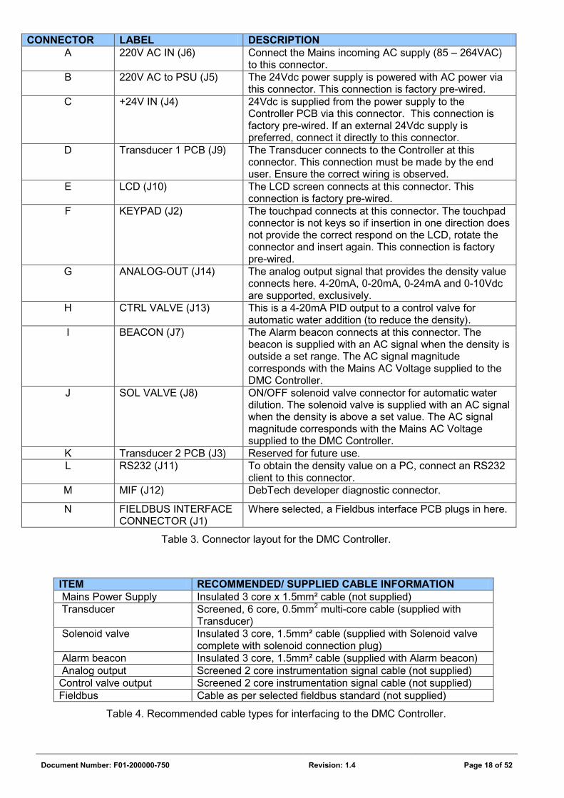
ITEM RECOMMENDED/ SUPPLIED CABLE INFORMATION Mains Power Supply Insulated 3 core x 1.5mm² cable (not supplied) Transducer Screened, 6 core, 0.5mm2 multi-core cable (supplied with
Transducer) Solenoid valve Insulated 3 core, 1.5mm² cable (supplied with Solenoid valve
complete with solenoid connection plug) Alarm beacon Insulated 3 core, 1.5mm² cable (supplied with Alarm beacon) Analog output Screened 2 core instrumentation signal cable (not supplied) Control valve output Screened 2 core instrumentation signal cable (not supplied) Fieldbus Cable as per selected fieldbus standard (not supplied)
Table 4. Recommended cable types for interfacing to the DMC Controller.
Document Number: F01-200000-750 Revision: 1.4 Page 19 of 52
It is highly recommended that this instrument be supplied with clean power, ideally from a UPS. In order to get the DMC functional, connections A and D are necessary. The DMC will then function and display the density on the LCD screen. In order to obtain an analog output from the DMC (for a PLC for example) connection G is necessary. If a Fieldbus option is selected, the connector on the Fieldbus PCB will be different for different types of Fieldbus options.
Cable lengths may be tailored to suit the installation.
Whilst connecting cables to the Controller it is important to ensure glands are fitted correctly and fully tightened. Unused cable entries must be sealed with a gland plug.
See APPENDIX A : for complete wiring diagram.
2.4.4 Earthing (grounding)
Proper earth connection is very important for accurate measurement of the Transducer. A floating earth will result in fluctuations in the measured density.
There are 2 methods of earth connectivity:
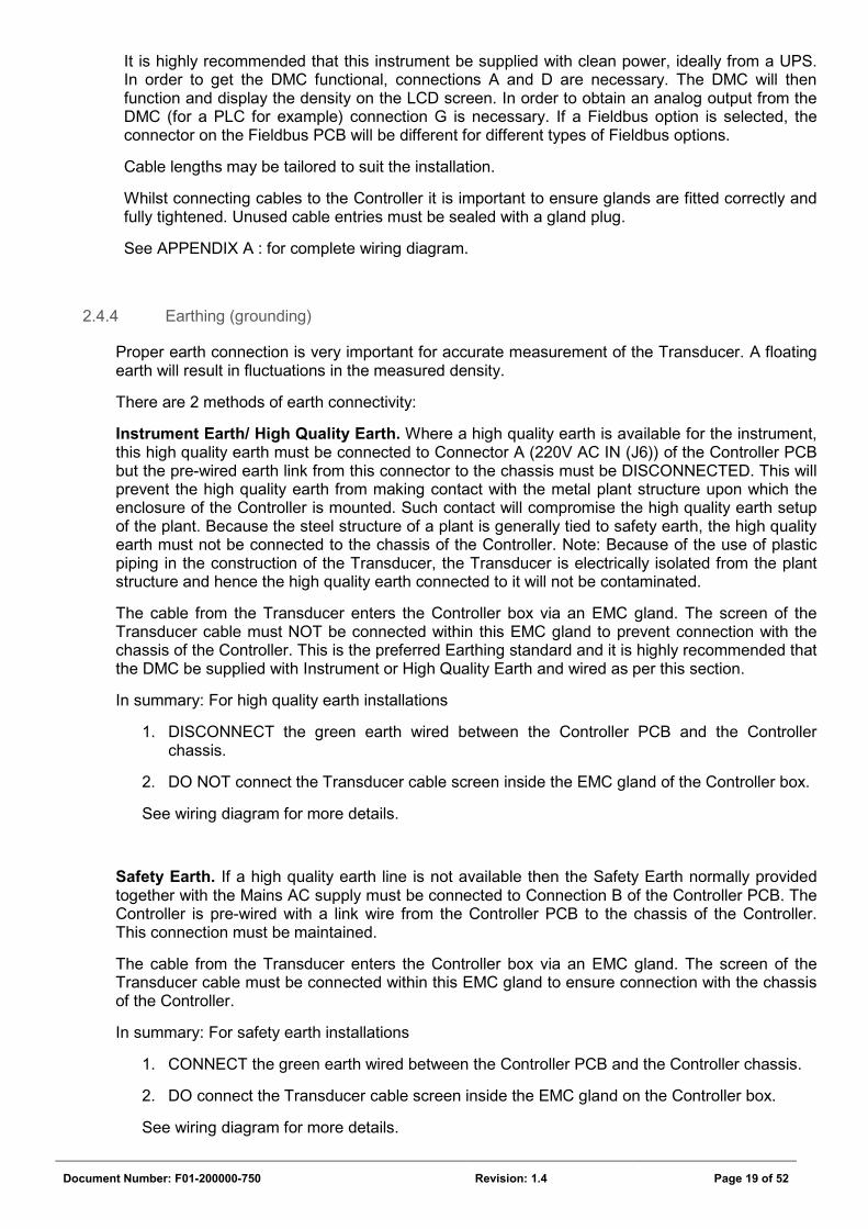
Instrument Earth/ High Quality Earth. Where a high quality earth is available for the instrument, this high quality earth must be connected to Connector A (220V AC IN (J6)) of the Controller PCB but the pre-wired earth link from this connector to the chassis must be DISCONNECTED. This will prevent the high quality earth from making contact with the metal plant structure upon which the enclosure of the Controller is mounted. Such contact will compromise the high quality earth setup of the plant. Because the steel structure of a plant is generally tied to safety earth, the high quality earth must not be connected to the chassis of the Controller. Note: Because of the use of plastic piping in the construction of the Transducer, the Transducer is electrically isolated from the plant structure and hence the high quality earth connected to it will not be contaminated.
The cable from the Transducer enters the Controller box via an EMC gland. The screen of the Transducer cable must NOT be connected within this EMC gland to prevent connection with the chassis of the Controller. This is the preferred Earthing standard and it is highly recommended that the DMC be supplied with Instrument or High Quality Earth and wired as per this section.
In summary: For high quality earth installations
1. DISCONNECT the green earth wired between the Controller PCB and the Controller chassis.
2. DO NOT connect the Transducer cable screen inside the EMC gland of the Controller box.
See wiring diagram for more details.
Safety Earth. If a high quality earth line is not available then the Safety Earth normally provided together with the Mains AC supply must be connected to Connection B of the Controller PCB. The Controller is pre-wired with a link wire from the Controller PCB to the chassis of the Controller. This connection must be maintained.
The cable from the Transducer enters the Controller box via an EMC gland. The screen of the Transducer cable must be connected within this EMC gland to ensure connection with the chassis of the Controller.
In summary: For safety earth installations
1. CONNECT the green earth wired between the Controller PCB and the Controller chassis.
2. DO connect the Transducer cable screen inside the EMC gland on the Controller box.
See wiring diagram for more details.
Document Number: F01-200000-750 Revision: 1.4 Page 20 of 52
2.4.5 Solenoid Valve installation
The Solenoid Valve is installed at a convenient position in the dilution water supply line as shown in Figure 3.
It is recommended that an in-line strainer be mounted upstream of the valve to remove suspended solids which may otherwise interfere with the correct working of the valve.
Additionally, to ensure consistent water dosing it is suggested that a regulating (ball or gate) valve is installed upstream of the solenoid valve and that the water supply is derived from a constant pressure source.
2.4.6 Alarm Beacon Installation
The Alarm Beacon should be installed at a position in the plant where it is readily visible to the plant operator. It may be mounted in a horizontal or vertically upwards position and attached securely to a suitable support structure. It must be installed in a location that will ensure it is not soiled by falling medium slurry that will impede its visibility.
2.5 Transducer Switch Setting
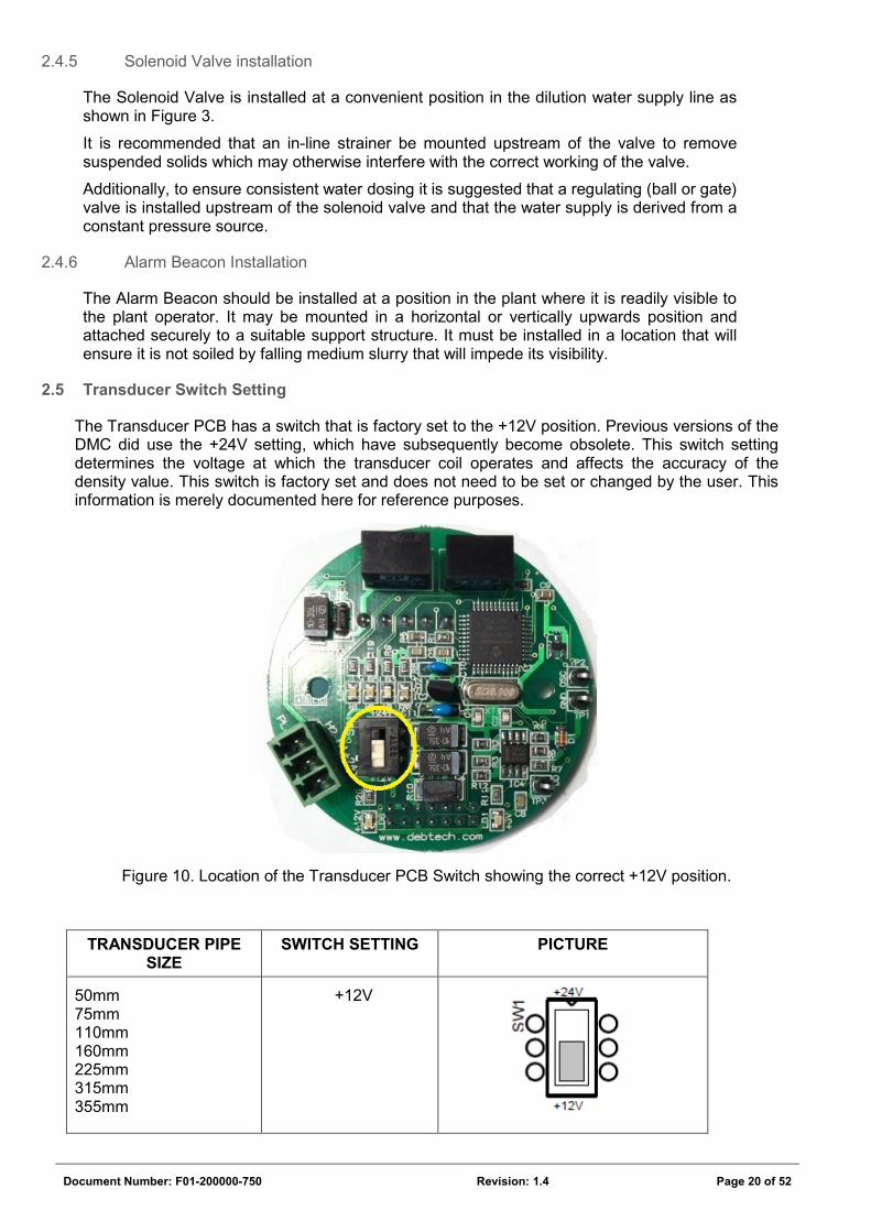
The Transducer PCB has a switch that is factory set to the +12V position. Previous versions of the DMC did use the +24V setting, which have subsequently become obsolete. This switch setting determines the voltage at which the transducer coil operates and affects the accuracy of the density value. This switch is factory set and does not need to be set or changed by the user. This information is merely documented here for reference purposes.
Figure 10. Location of the Transducer PCB Switch showing the correct +12V position.
TRANSDUCER PIPE SIZE
SWITCH SETTING PICTURE
50mm 75mm 110mm 160mm 225mm 315mm 355mm
+12V
Document Number: F01-200000-750 Revision: 1.4 Page 21 of 52
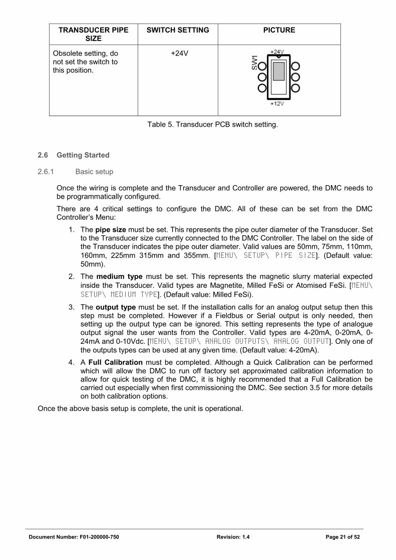
TRANSDUCER PIPE SIZE
SWITCH SETTING PICTURE
Obsolete setting, do not set the switch to this position.
+24V
Table 5. Transducer PCB switch setting.
2.6 Getting Started
2.6.1 Basic setup
Once the wiring is complete and the Transducer and Controller are powered, the DMC needs to be programmatically configured.
There are 4 critical settings to configure the DMC. All of these can be set from the DMC Controller’s Menu:
1. The pipe size must be set. This represents the pipe outer diameter of the Transducer. Set to the Transducer size currently connected to the DMC Controller. The label on the side of the Transducer indicates the pipe outer diameter. Valid values are 50mm, 75mm, 110mm, 160mm, 225mm 315mm and 355mm. [MENU\ SETUP\ PIPE SIZE]. (Default value: 50mm).
2. The medium type must be set. This represents the magnetic slurry material expected inside the Transducer. Valid types are Magnetite, Milled FeSi or Atomised FeSi. [MENU\ SETUP\ MEDIUM TYPE]. (Default value: Milled FeSi).
3. The output type must be set. If the installation calls for an analog output setup then this step must be completed. However if a Fieldbus or Serial output is only needed, then setting up the output type can be ignored. This setting represents the type of analogue output signal the user wants from the Controller. Valid types are 4-20mA, 0-20mA, 0-24mA and 0-10Vdc. [MENU\ SETUP\ ANALOG OUTPUTS\ ANALOG OUTPUT]. Only one of the outputs types can be used at any given time. (Default value: 4-20mA).
4. A Full Calibration must be completed. Although a Quick Calibration can be performed which will allow the DMC to run off factory set approximated calibration information to allow for quick testing of the DMC, it is highly recommended that a Full Calibration be carried out especially when first commissioning the DMC. See section 3.5 for more details on both calibration options.
Once the above basis setup is complete, the unit is operational.
Document Number: F01-200000-750 Revision: 1.4 Page 22 of 52
SECTION 3: OPERATING PROCEDURES
3.1 Operational Procedures
No start-up or shutdown procedure is necessary. The electrical supply to the DMC can simply be turned on or off. It is recommended that the Transducer is always powered even when the plant is not operational, unless necessary for safety or maintenance reasons, as the Transducer needs power to maintain the temperature of its electronics at a constant level for optimum results. This way, when the Transducer is needed for measurement it is ready at the correct temperature for accurate measurement.
3.2 Operating Sequences
When power is applied to the DMC, the system automatically initialises and outputs the density reading on the LCD display and to the analog output including any configured fieldbus interface. The DMC continuously updates these values every 5 seconds. It is safe to simply remove the power supplied to the DMC at any stage to shut it down. No start-up or shutdown sequences need to be manually carried out by the user.
3.3 Home Screen
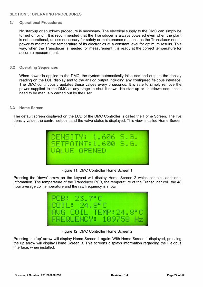
The default screen displayed on the LCD of the DMC Controller is called the Home Screen. The live density value, the control setpoint and the valve status is displayed. This view is called Home Screen 1.
Figure 11. DMC Controller Home Screen 1.
Pressing the ‘down’ arrow on the keypad will display Home Screen 2 which contains additional information. The temperature of the Transducer PCB, the temperature of the Transducer coil, the 48 hour average coil temperature and the raw frequency is shown.
Figure 12. DMC Controller Home Screen 2.
Pressing the ‘up’ arrow will display Home Screen 1 again. With Home Screen 1 displayed, pressing the up arrow will display Home Screen 3. This screens displays information regarding the Fieldbus interface, when installed.

Document Number: F01-200000-750 Revision: 1.4 Page 23 of 52
Figure 13. DMC Controller Home Screen 3.
Document Number: F01-200000-750 Revision: 1.4 Page 24 of 52
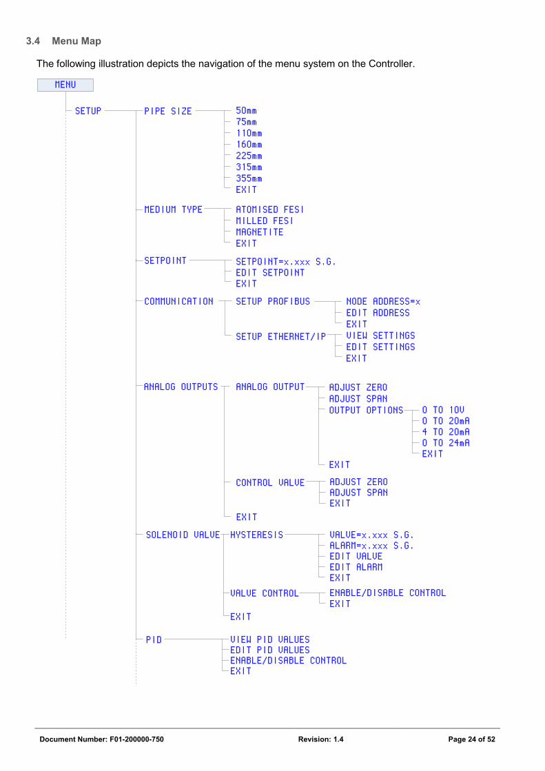
3.4 Menu Map
The following illustration depicts the navigation of the menu system on the Controller.
SETUP PIPE SIZE75mm110mm160mm225mm
50mm
315mm355mmEXIT
MEDIUM TYPE ATOMISED FESIMILLED FESIMAGNETITEEXIT
SETPOINT SETPOINT=x.xxx S.G.EDIT SETPOINTEXIT
COMMUNICATION SETUP PROFIBUS
SETUP ETHERNET/IP
ANALOG OUTPUTS ANALOG OUTPUT
CONTROL VALVE
EXIT
ADJUST ZEROADJUST SPANOUTPUT OPTIONS
EXIT
ADJUST ZEROADJUST SPANEXIT
0 TO 10V0 TO 20mA4 TO 20mA0 TO 24mAEXIT
SOLENOID VALVE
MENU
HYSTERESIS
VALVE CONTROL
EXIT
VALVE=x.xxx S.G.ALARM=x.xxx S.G.EDIT VALVEEDIT ALARMEXITENABLE/DISABLE CONTROLEXIT
PID VIEW PID VALUESEDIT PID VALUES
EXITENABLE/DISABLE CONTROL
NODE ADDRESS=xEDIT ADDRESSEXIT
EDIT SETTINGSVIEW SETTINGS
EXIT
Document Number: F01-200000-750 Revision: 1.4 Page 25 of 52
EXIT
SETUP
CALIBRATE
RECORDED ERRORSSEND ERROR LISTCLEAR ERROR LIST
VIEW ERROR LIST
EXIT
VIEW SETTINGS PIPE SIZE xxxmmOUTPUT xxx<Medium type selected>SETPOINT: x.xxx S.G.
MENU
HYSTERESIS: x.xxx S.G.Frequency: xxxxx Hz.Gradient (A): xxxxxY Intcpt.(B): xxxxxCOIL AVERAGE: xx.x 0CCALIB. TEMP: xx.x 0CHz/0C: xxPCB SETPOINT: xx0CHz/0C AVERAGE: xxCOMP1: xxHz.COMP2: xxHz.LOWER SG: x.xxx S.G.LOWER TEMP: xx.x 0CLOWER Hz: xxxxxHIGHER SG: x.xxx S.G.HIGHER TEMP: xx.x 0CHIGHER Hz: xxxxx
RESET DEFAULTSEXITQUICK CALIBRATIONFULL CALIBRATION
EXIT
DEFINE LOWER S.G.DEFINE HIGHER S.G.FULL CALIBRATEEXIT
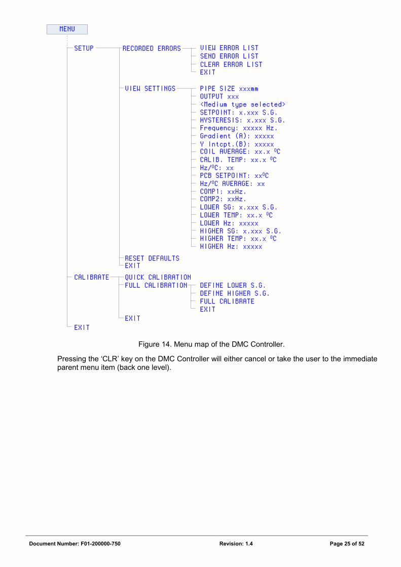
Figure 14. Menu map of the DMC Controller.
Pressing the ‘CLR’ key on the DMC Controller will either cancel or take the user to the immediate parent menu item (back one level).
Document Number: F01-200000-750 Revision: 1.4 Page 26 of 52
3.5 Calibration
The DMC has 2 calibration procedures, a Full Calibration and a Quick Calibration.
3.5.1 Full Calibration
Although a Full Calibration is a more involved method of calibration, it is very important to set up the DMC for accurate measurement. A Full Calibration must be done at least once on initial installation in order for the built-in calibration information to be updated with site specific characteristics (for example: the unique properties of the medium type). Whenever there is a change in medium type (be it a change in grade or supplier) or when unacceptable accuracies are observed at higher and lower S.G. values, a Full Calibration should once again be performed. Unlike the Quick Calibration, the Full Calibration requires process adjustment. Hand sample readings are taken at higher and lower S.G. values (with reference to the normal operating density of the plant). The plant must be adjusted to a density level below the normal operational density and the Lower SG value recorded, and then the plant adjusted to a higher density level so that the Higher SG value can be recorded. Following this a Full Calibration can be executed. The Controller then calculates an accurate calibration dataset and updates its permanent memory so that any Quick Calibration subsequently performed is based on the calibration dataset obtained during the Full Calibration.
Full Calibration Steps: Case assumption: Plant operates at 1.60 S.G. normally.
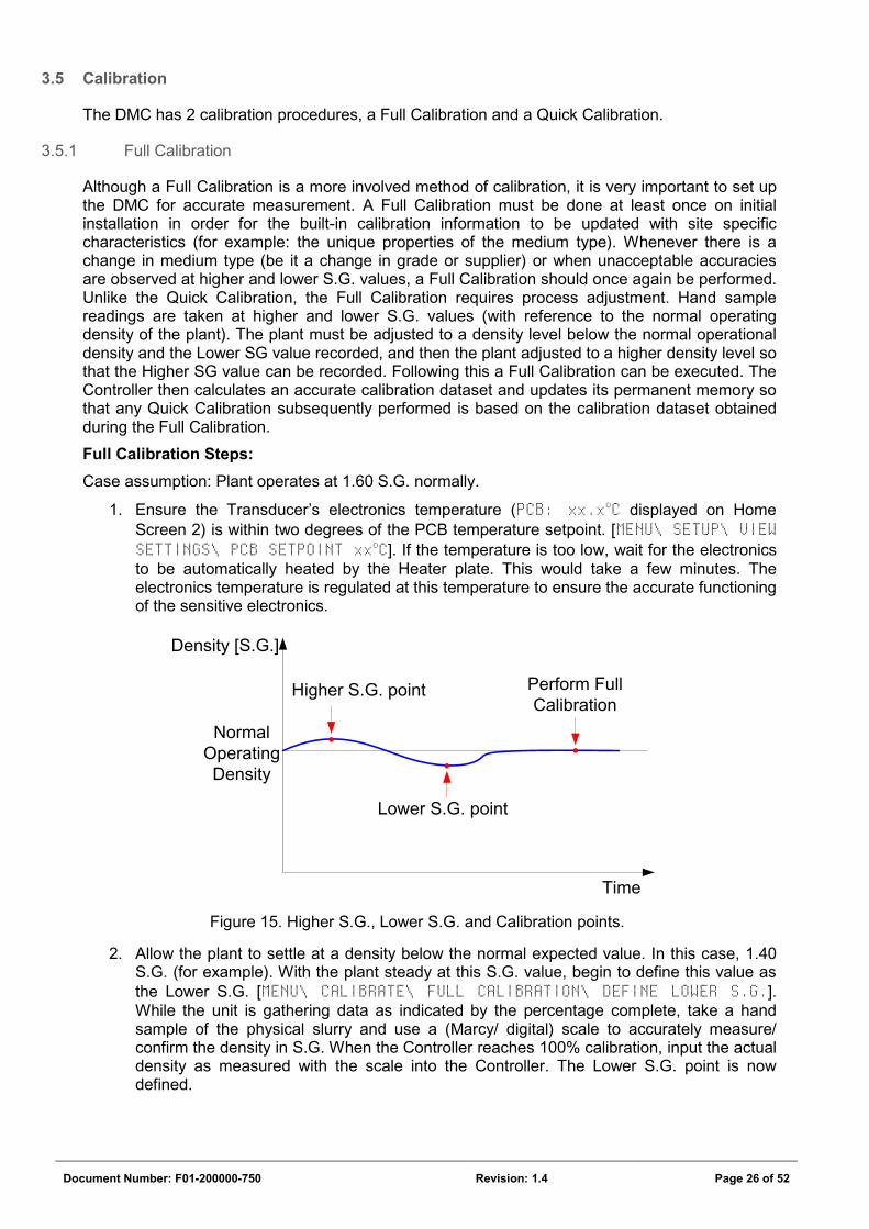
1. Ensure the Transducer’s electronics temperature (PCB: xx.xoC displayed on Home Screen 2) is within two degrees of the PCB temperature setpoint. [MENU\ SETUP\ VIEW SETTINGS\ PCB SETPOINT xxoC]. If the temperature is too low, wait for the electronics to be automatically heated by the Heater plate. This would take a few minutes. The electronics temperature is regulated at this temperature to ensure the accurate functioning of the sensitive electronics.
Normal Operating Density
Density [S.G.]
Time
Higher S.G. point
Lower S.G. point
Perform Full Calibration
Figure 15. Higher S.G., Lower S.G. and Calibration points.
2. Allow the plant to settle at a density below the normal expected value. In this case, 1.40 S.G. (for example). With the plant steady at this S.G. value, begin to define this value as the Lower S.G. [MENU\ CALIBRATE\ FULL CALIBRATION\ DEFINE LOWER S.G.]. While the unit is gathering data as indicated by the percentage complete, take a hand sample of the physical slurry and use a (Marcy/ digital) scale to accurately measure/ confirm the density in S.G. When the Controller reaches 100% calibration, input the actual density as measured with the scale into the Controller. The Lower S.G. point is now defined.
Document Number: F01-200000-750 Revision: 1.4 Page 27 of 52
3. Now to define the Higher S.G. point, allow the plant to settle at a density above the normal expected value. In this case, 1.80 S.G. (for example). With the plant steady at this S.G. value, begin to define this value as the Higher S.G. [MENU\ CALIBRATE\ FULL CALIBRATION\ DEFINE HIGHER S.G.]. While the unit is gathering data as indicated by the percentage complete, take a hand sample of the physical slurry and use a (Marcy/ digital) scale to accurately measure/ confirm the density. When the Controller reaches 100% calibration, input the actual density as measured with the scale into the Controller. The Higher S.G. point is now defined.
NOTE: The Higher or Lower S.G. point can be done in any sequence, at any time. For example, plant dynamics may mean the Higher S.G. can be defined presently and the Lower S.G. can only be defined 1 day later. The Controller simple stores the data for the higher and lower points as they are updated and only does the Full Calibration when the user requests it.
4. Once the Lower and Higher SG points have been defined, the plant can be adjusted to its normal density, say 1.60 S.G. as in this case. To complete the Full Calibration the unit must be made to perform a Full Calibration. Note, when a Full Calibration is requested, the Controller works off the data already stored as the Lower and Higher S.G., so ensure they are defined first before performing a Full Calibration. To perform a Full Calibration based on the defined Lower and Higher S.G., select Full Calibrate. [MENU\ CALIBRATE\ FULL CALIBRATION\ FULL CALIBRATE]. While the unit is calibrating as indicated by the percentage complete, take a final hand sample of the physical slurry and use a (Marcy/ digital) scale to accurately measure the density. When the Controller reaches 100% calibration, input the actual density as measured with the scale into the Controller. A Full Calibration is now complete and the calibration curve data is updated based on the Lower and Higher S.G. points. This allows for consecutive Quick Calibrations to be performed accurately for this plant.
NOTE The Controller stores the Higher S.G., Lower S.G. and Calibration data in permanent
memory as and when they are defined by the user so that even if the electrical power is recycled at any stage the information is not lost.
NOTE The Higher and Lower S.G. values only take effect when a Full Calibrate is performed.
TIPS:
There are various methods of choosing the Higher and Lower S.G. points. The best is to choose a point equally higher and lower from the normal operating density as detailed above. However this is not always practical.
On some plants it is operationally difficult to get the density to a higher value. In such a case a Lower S.G. point can be saved as explained above but the Higher S.G. point can be chosen as the same point the plant normally runs at (and not a higher value as ideally recommended). A Full Calibration with these 2 points will still yield an accurate calibration result.
In other cases there may be no room to adjust the plant from its normal operating density. In such cases when the plant is not running and with no medium inside the DMC Transducer (for example during DMC installation or during a maintenance shutdown) the Lower S.G. point can be saved with air or pure water inside the DMC Transducer. In such a case a density of 1.000 S.G. must be entered. This is performed in the factory with air inside the unit and can be confirmed by looking at the data in the View Settings section of the Menu. The Higher S.G.
Document Number: F01-200000-750 Revision: 1.4 Page 28 of 52
point can be saved at the normal operating density of the plant. A Full Calibration with these 2 points will still yield a reliable calibration result.
3.5.2 Quick Calibration
A Quick calibration allows for speedy calibration of the medium based on one hand sample. When the plant is running under stable conditions (a steady medium density is achieved) initiate a Quick Calibration on the Controller, take a hand sample (for example using a Marcy Scale) and then input the density value read off the Marcy scale into the Controller. The DMC then runs off the default calibration formula in conjunction with the entered Marcy scale reading. Note: The major advantage of a Quick Calibration is that it is done at the plant’s current running density and process adjustment is not required.
The DMC is factory coded with default calibration values that were obtained from practical plant test-work. However it is important to perform a Full Calibration so that accurate site specific calibration values are calculated to ensure accurate density readings. A Full Calibration updates the default calibration data so that any subsequent Quick Calibration, which always runs off the calibration data updated by a Full Calibration, is then based on unique site specific calibration information.
IMPORTANT
It is recommended that a Quick Calibration be done once a week.
Quick Calibration Steps: Case assumption: Plant operates at 1.60 S.G. normally.
1. Ensure the Transducer Electronics Temperature (displayed on Home Screen 2) is within two degrees of the PCB temperature setpoint. [MENU\ SETUP\ VIEW SETTINGS\ PCB SETPOINT]. If the temperature is too low, wait for the electronics to be automatically heated by the Heater plate.
2. Allow the plant to settle at its normal density value. In this case, 1.60 S.G. (for example). Select Quick Calibration. [MENU\ CALIBRATE\ QUICK CALIBRATION].
3. While the unit is calibrating as indicated by the percentage complete, take a hand sample of the physical slurry and use a (Marcy/ digital) scale to measure the density.
4. When the Controller reaches 100% calibration, input the actual density as measured with the scale. A Quick Calibration is now complete. The unit is ready for operation.
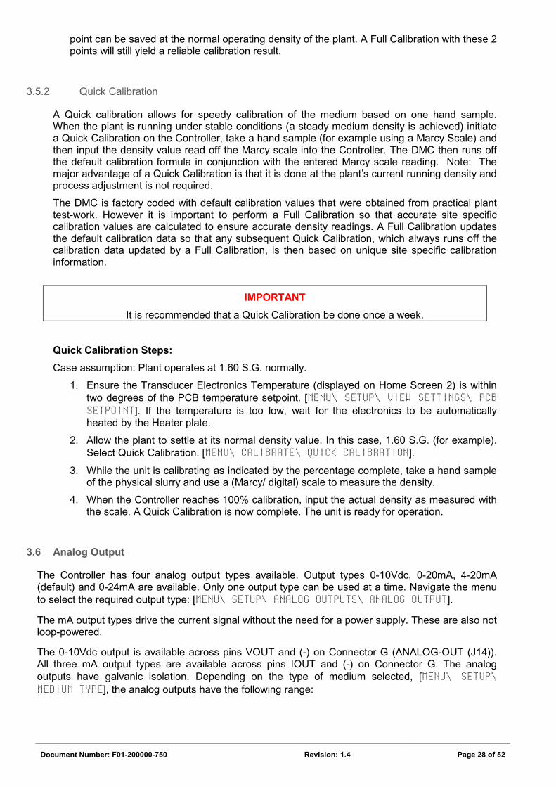
3.6 Analog Output
The Controller has four analog output types available. Output types 0-10Vdc, 0-20mA, 4-20mA (default) and 0-24mA are available. Only one output type can be used at a time. Navigate the menu to select the required output type: [MENU\ SETUP\ ANALOG OUTPUTS\ ANALOG OUTPUT].
The mA output types drive the current signal without the need for a power supply. These are also not loop-powered.
The 0-10Vdc output is available across pins VOUT and (-) on Connector G (ANALOG-OUT (J14)). All three mA output types are available across pins IOUT and (-) on Connector G. The analog outputs have galvanic isolation. Depending on the type of medium selected, [MENU\ SETUP\ MEDIUM TYPE], the analog outputs have the following range:
Document Number: F01-200000-750 Revision: 1.4 Page 29 of 52
MEDIUM TYPE ANALOG OUTPUT TYPE RANGE
Atomised FeSi
0-10Vdc
1.00 to 4.50 S.G.
0-20mA
4-20mA
0-24mA
Milled FeSi
0-10Vdc
1.00 to 3.80 S.G.
0-20mA
4-20mA
0-24mA
Magnetite
0-10Vdc
1.00 to 2.20 S.G.
0-20mA
4-20mA
0-24mA
Table 6. Analog output range per medium type.
3.6.1 Zero and Span adjustment of the Analog output port
The Analog output port is factory calibrated to their respective minimum and maximum values as per the output type.
To check/ confirm the calibration of this output:
1. Connect a voltmeter or ammeter to the correct pins as described above for the type of output signal to be measured.
2. From the Menu navigate to MENU\ SETUP\ ANALOG OUTPUTS\ ANALOG OUTPUT\ OUTPUT OPTIONS and select the correct analog output type required.
3. From the Menu select MENU\ SETUP\ ANALOG OUTPUTS\ ANALOG OUTPUT\ ADJUST ZERO.
4. The LCD display will read: ANALOG SETUP. ANALOG held at min. Adjust ZERO 1 pot. Press OK when done.
5. Using a terminal screwdriver, adjust the ZERO 1 potentiometer (VR2) on the Controller PCB until the minimal voltage or current for the selected analog output type is measured. The minimum range value for the Analog output port is now calibrated.
6. From the Menu select MENU\ SETUP\ ANALOG OUTPUTS\ ANALOG OUTPUT\ ADJUST SPAN.
7. The LCD display will read: ANALOG SETUP. ANALOG held at max. Adjust SPAN 1 pot. Press OK when done.
8. Using a terminal screwdriver, adjust the SPAN 1 potentiometer (VR3) on the Controller PCB until the maximum voltage or current for the selected analog output type is measured. The maximum range value for the Analog output port is now calibrated.
Document Number: F01-200000-750 Revision: 1.4 Page 30 of 52
3.7 Serial Output
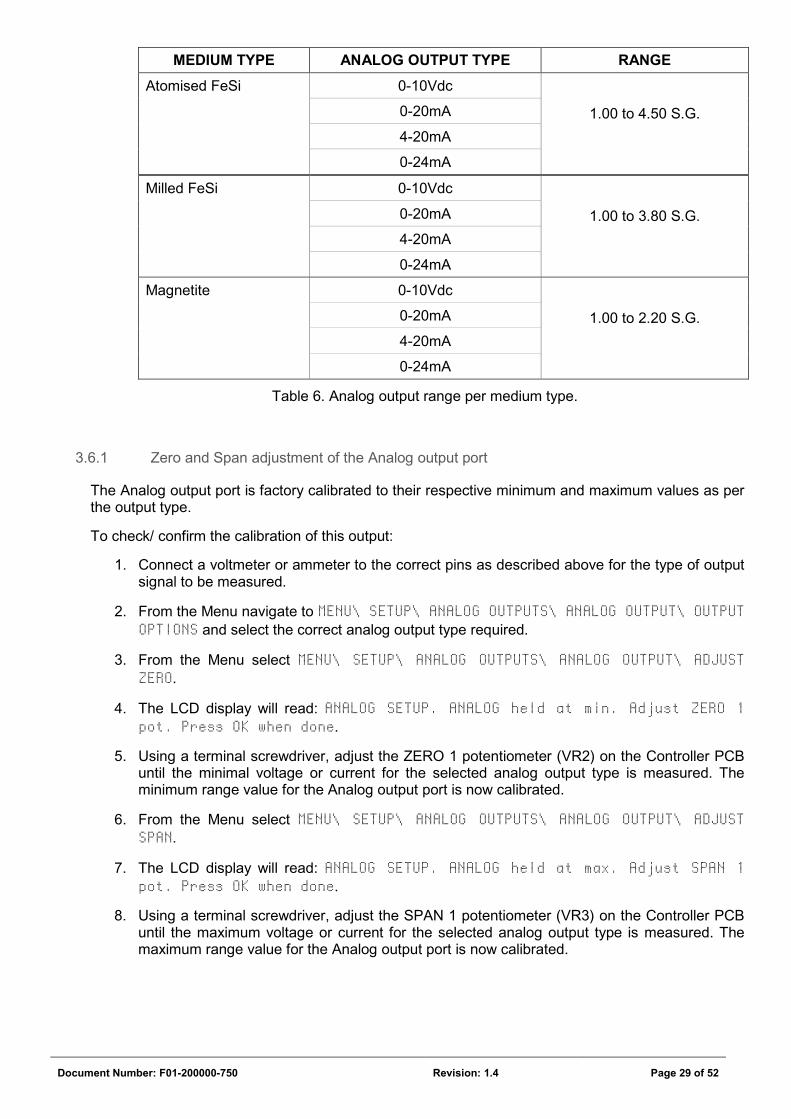
The DMC Controller outputs the density value over an RS 232 serial interface. This interface is available as standard on the DMC Controller and is useful when the user wants to obtain the density using an RS232 client such as a computer or data logger. The calculated density value is always transmitted every 5 seconds over this interface and no setup is necessary. (See section 3.11 Advanced Settings to change the update rate.) The serial output of the DMC Controller is unidirectional and data is only transmitted from the DMC Controller to a client. In order to use this interface connect a serial cable to Connection L as per the wiring diagram. Ensure that the transmit pin (TX) on Connection L is connected to the receive pin on the RS232 client. Only the TX, RX and GND lines are needed.
F01-200700 DMC Controller PCB
2
1
3
2
1
3
RS232
J11
RX
TX
0V
(CRX3)
(CTX3)
(0V6)
(CRX3)
(CTX3)
(0V6)
2
3
5
RS232 port
RS232 client
9 pin female D-Sub
RX
TX
GND
Figure 16. Interfacing to the Serial Port.
Once the hardware is connected, use a serial port software application such as Windows HyperTerminal running on a PC to test the communication to the DMC Controller. The default serial port settings of the DMC Controller are:
Baud rate: 9600
Data bits: 8
Parity: No
Stop bits: 1
Hardware flow control
Configure the serial client (user’s device) with the above serial port settings. Once this is done and the port is opened, the data sent from the DMC Controller every 5 seconds will look:
55.3,27.4,23.4,1601,26812,26812,26772,0,0,0,0,0 followed by a Carriage Return.
This example stream of data is a comma separated data set which ends with a carriage return. Using the commas to separate the data, the data represents the following headings of information:
PCB temp.
Coil temp.
Coil average temp.
Density Raw freq.
Comp. freq. 1
Comp. freq. 2
Error 1
Error 2
Error 3
Error 4
Error 5
55.3 27.4 23.4 1601 26812 26812 26772 0 0 0 0 0
Table 7. Definition of the data stream at the Serial Output.
The Density can be stripped from the data stream between the 3rd and 4th comma. This value is in milli S.G. such that 1601 represents a true density of 1.601 S.G.
There are many applications that can read this data stream and store it as a comma separated variable (.csv) file for analysis and trending in a program such as Microsoft Excel (for example).
Document Number: F01-200000-750 Revision: 1.4 Page 31 of 52
3.8 On/ Off Controller Output
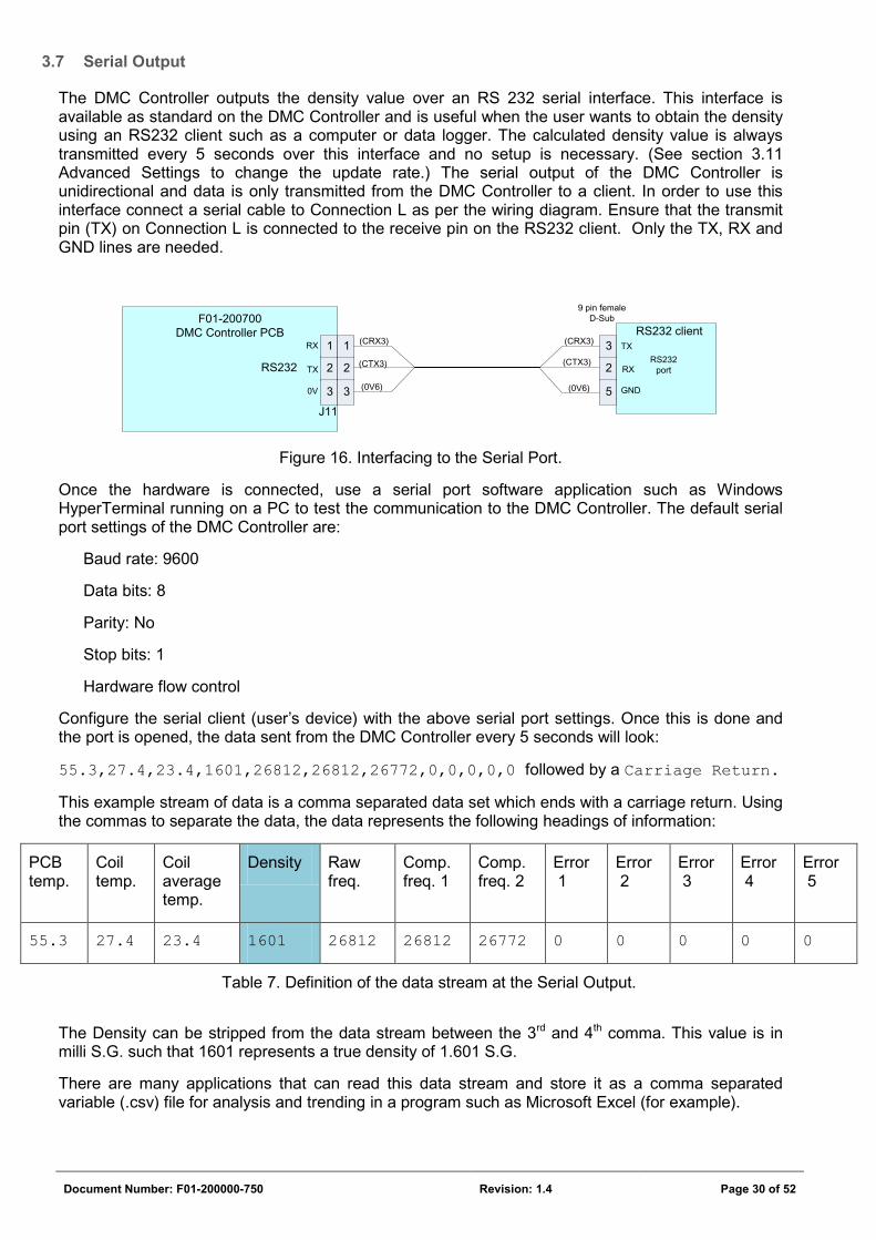
The DMC Controller contains an ON/ OFF (a.k.a. Bang Bang) Controller for the operation of a solenoid valve (optional item). If the density goes too high the Solenoid valve is opened to add dilution water to bring the density down. When the density is below a limit the valve is then closed. The DMC Controller can operate in either ON/ OFF Controller or PID Controller mode, not in both modes at the same time. Given a Valve setpoint, if the density exceeds the setpoint plus the hysteresis value the output at SOL VALVE (connection J) goes high (Mains AC voltage) to open a solenoid valve in order to add dilution water. If the density goes below the setpoint minus the hysteresis value the output goes low (0Vac) to shut off the valve. The ON/ OFF Controller assumes that a high signal will open the solenoid valve.
NOTE The ON /OFF Controller activates a 220Vac relay to open or close a solenoid valve.
It therefore needs an AC supply. This output will not work if the DMC is supplied directly with 24Vdc (by bypassing the internal power supply).
1. To use the ON/ OFF Controller, firstly navigate the menu [MENU\ SETUP\ SOLENOID VALVE\ VALVE CONTROL\ ENABLE/DISABLE CONTROL] and enable ON/ OFF control.
2. Edit the Setpoint at which the Valve must operate [MENU\ SETUP\ SETPOINT\ EDIT SETPOINT]. To view the current solenoid valve setpoint navigate to [MENU\ SETUP\ SETPOINT\ SETPOINT]. The default Setpoint value is 1.600 S.G.
3. Edit the Solenoid valve hysteresis value [MENU\ SETUP\ SOLENOID VALVE\ HYSTERESIS\ VALVE]. To view the current solenoid valve hysteresis value go to [MENU\ SETUP \SOLENOID VALVE\ HYSTERESIS\ VALVE=x.xxx S.G.]. The default hysteresis value is 0.050 S.G.
Figure 17. Illustration of the operation of the Solenoid Valve.
Valve Setpoint
Valve Setpoint + Valve Hysteresis
Valve Setpoint - Valve Hysteresis
Density [S.G.]
Time
Solenoid Valve activated
Solenoid Valve deactivated
Document Number: F01-200000-750 Revision: 1.4 Page 32 of 52
3.9 PID Controller Output
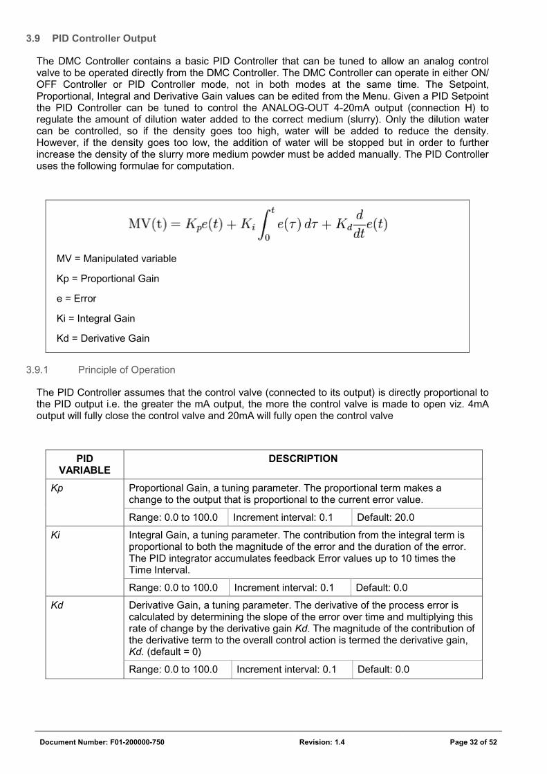
The DMC Controller contains a basic PID Controller that can be tuned to allow an analog control valve to be operated directly from the DMC Controller. The DMC Controller can operate in either ON/ OFF Controller or PID Controller mode, not in both modes at the same time. The Setpoint, Proportional, Integral and Derivative Gain values can be edited from the Menu. Given a PID Setpoint the PID Controller can be tuned to control the ANALOG-OUT 4-20mA output (connection H) to regulate the amount of dilution water added to the correct medium (slurry). Only the dilution water can be controlled, so if the density goes too high, water will be added to reduce the density. However, if the density goes too low, the addition of water will be stopped but in order to further increase the density of the slurry more medium powder must be added manually. The PID Controller uses the following formulae for computation.
MV = Manipulated variable
Kp = Proportional Gain
e = Error
Ki = Integral Gain
Kd = Derivative Gain
3.9.1 Principle of Operation
The PID Controller assumes that the control valve (connected to its output) is directly proportional to the PID output i.e. the greater the mA output, the more the control valve is made to open viz. 4mA output will fully close the control valve and 20mA will fully open the control valve
PID VARIABLE
DESCRIPTION
Kp Proportional Gain, a tuning parameter. The proportional term makes a change to the output that is proportional to the current error value.
Range: 0.0 to 100.0 Increment interval: 0.1 Default: 20.0
Ki Integral Gain, a tuning parameter. The contribution from the integral term is proportional to both the magnitude of the error and the duration of the error. The PID integrator accumulates feedback Error values up to 10 times the Time Interval.
Range: 0.0 to 100.0 Increment interval: 0.1 Default: 0.0
Kd Derivative Gain, a tuning parameter. The derivative of the process error is calculated by determining the slope of the error over time and multiplying this rate of change by the derivative gain Kd. The magnitude of the contribution of the derivative term to the overall control action is termed the derivative gain, Kd. (default = 0)
Range: 0.0 to 100.0 Increment interval: 0.1 Default: 0.0
Document Number: F01-200000-750 Revision: 1.4 Page 33 of 52
PID VARIABLE
DESCRIPTION
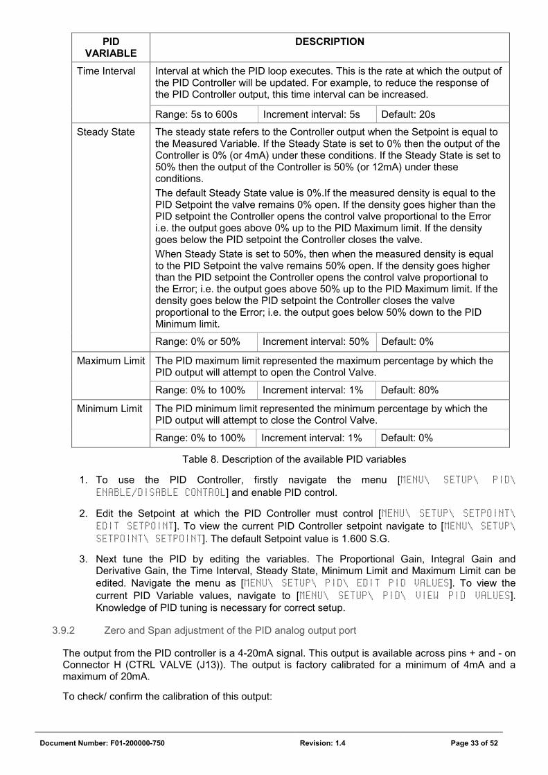
Time Interval Interval at which the PID loop executes. This is the rate at which the output of the PID Controller will be updated. For example, to reduce the response of the PID Controller output, this time interval can be increased.
Range: 5s to 600s Increment interval: 5s Default: 20s
Steady State The steady state refers to the Controller output when the Setpoint is equal to the Measured Variable. If the Steady State is set to 0% then the output of the Controller is 0% (or 4mA) under these conditions. If the Steady State is set to 50% then the output of the Controller is 50% (or 12mA) under these conditions.
The default Steady State value is 0%.If the measured density is equal to the PID Setpoint the valve remains 0% open. If the density goes higher than the PID setpoint the Controller opens the control valve proportional to the Error i.e. the output goes above 0% up to the PID Maximum limit. If the density goes below the PID setpoint the Controller closes the valve.
When Steady State is set to 50%, then when the measured density is equal to the PID Setpoint the valve remains 50% open. If the density goes higher than the PID setpoint the Controller opens the control valve proportional to the Error; i.e. the output goes above 50% up to the PID Maximum limit. If the density goes below the PID setpoint the Controller closes the valve proportional to the Error; i.e. the output goes below 50% down to the PID Minimum limit.
Range: 0% or 50% Increment interval: 50% Default: 0%
Maximum Limit The PID maximum limit represented the maximum percentage by which the PID output will attempt to open the Control Valve.
Range: 0% to 100% Increment interval: 1% Default: 80%
Minimum Limit The PID minimum limit represented the minimum percentage by which the PID output will attempt to close the Control Valve.
Range: 0% to 100% Increment interval: 1% Default: 0%
Table 8. Description of the available PID variables
1. To use the PID Controller, firstly navigate the menu [MENU\ SETUP\ PID\ ENABLE/DISABLE CONTROL] and enable PID control.
2. Edit the Setpoint at which the PID Controller must control [MENU\ SETUP\ SETPOINT\ EDIT SETPOINT]. To view the current PID Controller setpoint navigate to [MENU\ SETUP\ SETPOINT\ SETPOINT]. The default Setpoint value is 1.600 S.G.
3. Next tune the PID by editing the variables. The Proportional Gain, Integral Gain and Derivative Gain, the Time Interval, Steady State, Minimum Limit and Maximum Limit can be edited. Navigate the menu as [MENU\ SETUP\ PID\ EDIT PID VALUES]. To view the current PID Variable values, navigate to [MENU\ SETUP\ PID\ VIEW PID VALUES]. Knowledge of PID tuning is necessary for correct setup.
3.9.2 Zero and Span adjustment of the PID analog output port
The output from the PID controller is a 4-20mA signal. This output is available across pins + and - on Connector H (CTRL VALVE (J13)). The output is factory calibrated for a minimum of 4mA and a maximum of 20mA.
To check/ confirm the calibration of this output:
Document Number: F01-200000-750 Revision: 1.4 Page 34 of 52
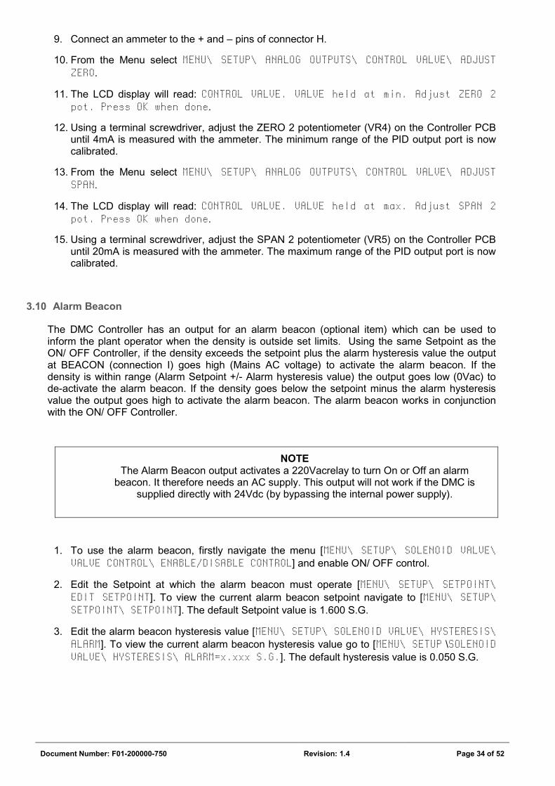
9. Connect an ammeter to the + and – pins of connector H.
10. From the Menu select MENU\ SETUP\ ANALOG OUTPUTS\ CONTROL VALVE\ ADJUST ZERO.
11. The LCD display will read: CONTROL VALVE. VALVE held at min. Adjust ZERO 2 pot. Press OK when done.
12. Using a terminal screwdriver, adjust the ZERO 2 potentiometer (VR4) on the Controller PCB until 4mA is measured with the ammeter. The minimum range of the PID output port is now calibrated.
13. From the Menu select MENU\ SETUP\ ANALOG OUTPUTS\ CONTROL VALVE\ ADJUST SPAN.
14. The LCD display will read: CONTROL VALVE. VALVE held at max. Adjust SPAN 2 pot. Press OK when done.
15. Using a terminal screwdriver, adjust the SPAN 2 potentiometer (VR5) on the Controller PCB until 20mA is measured with the ammeter. The maximum range of the PID output port is now calibrated.
3.10 Alarm Beacon
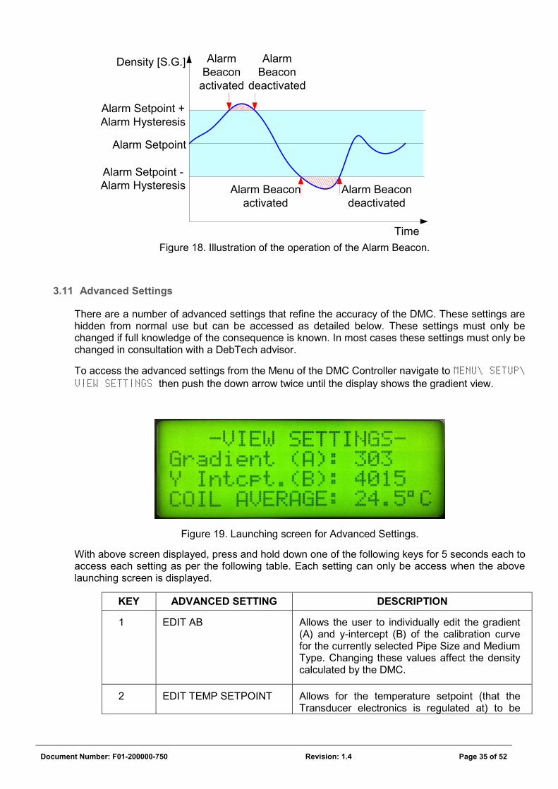
The DMC Controller has an output for an alarm beacon (optional item) which can be used to inform the plant operator when the density is outside set limits. Using the same Setpoint as the ON/ OFF Controller, if the density exceeds the setpoint plus the alarm hysteresis value the output at BEACON (connection I) goes high (Mains AC voltage) to activate the alarm beacon. If the density is within range (Alarm Setpoint +/- Alarm hysteresis value) the output goes low (0Vac) to de-activate the alarm beacon. If the density goes below the setpoint minus the alarm hysteresis value the output goes high to activate the alarm beacon. The alarm beacon works in conjunction with the ON/ OFF Controller.
NOTE The Alarm Beacon output activates a 220Vacrelay to turn On or Off an alarm
beacon. It therefore needs an AC supply. This output will not work if the DMC is supplied directly with 24Vdc (by bypassing the internal power supply).
1. To use the alarm beacon, firstly navigate the menu [MENU\ SETUP\ SOLENOID VALVE\ VALVE CONTROL\ ENABLE/DISABLE CONTROL] and enable ON/ OFF control.
2. Edit the Setpoint at which the alarm beacon must operate [MENU\ SETUP\ SETPOINT\ EDIT SETPOINT]. To view the current alarm beacon setpoint navigate to [MENU\ SETUP\ SETPOINT\ SETPOINT]. The default Setpoint value is 1.600 S.G.
3. Edit the alarm beacon hysteresis value [MENU\ SETUP\ SOLENOID VALVE\ HYSTERESIS\ ALARM]. To view the current alarm beacon hysteresis value go to [MENU\ SETUP \SOLENOID VALVE\ HYSTERESIS\ ALARM=x.xxx S.G.]. The default hysteresis value is 0.050 S.G.
Document Number: F01-200000-750 Revision: 1.4 Page 35 of 52
Figure 18. Illustration of the operation of the Alarm Beacon.
3.11 Advanced Settings
There are a number of advanced settings that refine the accuracy of the DMC. These settings are hidden from normal use but can be accessed as detailed below. These settings must only be changed if full knowledge of the consequence is known. In most cases these settings must only be changed in consultation with a DebTech advisor.
To access the advanced settings from the Menu of the DMC Controller navigate to MENU\ SETUP\ VIEW SETTINGS then push the down arrow twice until the display shows the gradient view.
Figure 19. Launching screen for Advanced Settings.
With above screen displayed, press and hold down one of the following keys for 5 seconds each to access each setting as per the following table. Each setting can only be access when the above launching screen is displayed.
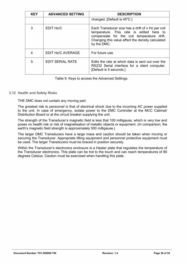
KEY ADVANCED SETTING DESCRIPTION
1 EDIT AB Allows the user to individually edit the gradient (A) and y-intercept (B) of the calibration curve for the currently selected Pipe Size and Medium Type. Changing these values affect the density calculated by the DMC.
2 EDIT TEMP SETPOINT Allows for the temperature setpoint (that the Transducer electronics is regulated at) to be
Alarm Setpoint
Alarm Setpoint + Alarm Hysteresis
Alarm Setpoint - Alarm Hysteresis
Density [S.G.]
Time
Alarm Beacon
activated
Alarm Beacon deactivated
Alarm Beacon activated
Alarm Beacon
deactivated
Document Number: F01-200000-750 Revision: 1.4 Page 36 of 52
KEY ADVANCED SETTING DESCRIPTION changed. [Default is 45oC.]
3 EDIT Hz/C Each Transducer size has a drift of x Hz per coil temperature. This rate is edited here to compensate for the coil temperature drift. Changing this value affect the density calculated by the DMC.
4 EDIT Hz/C AVERAGE For future use.
5 EDIT SERIAL RATE Edits the rate at which data is sent out over the RS232 Serial interface for a client computer. [Default is 5 seconds.]
Table 9. Keys to access the Advanced Settings.
3.12 Health and Safety Risks
THE DMC does not contain any moving part.
The greatest risk to personnel is that of electrical shock due to the incoming AC power supplied to the unit. In case of emergency, isolate power to the DMC Controller at the MCC Cabinet/ Distribution Board or at the circuit breaker supplying the unit.
The strength of the Transducer’s magnetic field is less that 100 milligauss, which is very low and poses no health risk or risk of magnetisation of metallic objects or equipment. (In comparison, the earth’s magnetic field strength is approximately 500 milligause.)
The larger DMC Transducers have a large mass and caution should be taken when moving or securing the Transducer. Appropriate lifting equipment and personnel protective equipment must be used. The larger Transducers must be braced in position securely.
Within the Transducer’s electronics enclosure is a Heater plate that regulates the temperature of the Transducer electronics. This plate can be hot to the touch and can reach temperatures of 80 degrees Celsius. Caution must be exercised when handling this plate.
Document Number: F01-200000-750 Revision: 1.4 Page 37 of 52
SECTION 4: FIELDBUS
4.1 Generic Fieldbus Information
The DMC Controller PCB can accommodate various fieldbus interfaces. A separate optional plug-in circuit board needs to be purchased for this option to be used. There are currently 3 fieldbus options that are supported, namely Profibus DP, Ethernet/IP and Modbus/TCP. Various other fieldbus standards will be supported if customer demand warrants them. The DMC hardware as designed can support DeviceNet, CANbus, ModBus and ProfiNet however additional software needs to be finalised to make these fieldbus standards available to customers.
The information made available over any fieldbus interface is read only. No parameter can be edited and no action can be initiated on the DMC Controller via any fieldbus Interface. The fieldbus interface is unidirectional. Data is only transmitted from the DMC Controller and no data is read.
DISCLAIMER All fieldbus application notes and sample projects are presented as a guide to achieve fieldbus communication and should not be used as a total plant solution without further refinement and
adaption for robust plant control.
4.1.1 Information available over fieldbus interface
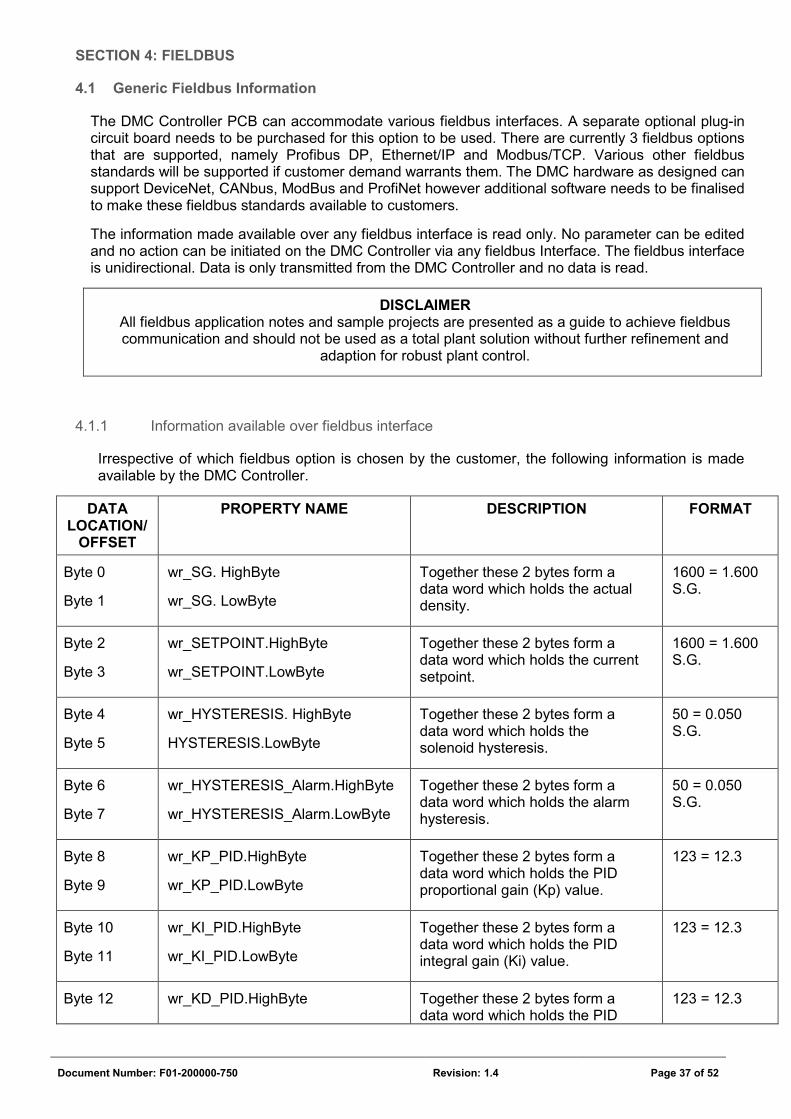
Irrespective of which fieldbus option is chosen by the customer, the following information is made available by the DMC Controller.
DATA LOCATION/
OFFSET
PROPERTY NAME DESCRIPTION FORMAT
Byte 0
Byte 1
wr_SG. HighByte
wr_SG. LowByte
Together these 2 bytes form a data word which holds the actual density.
1600 = 1.600 S.G.
Byte 2
Byte 3
wr_SETPOINT.HighByte
wr_SETPOINT.LowByte
Together these 2 bytes form a data word which holds the current setpoint.
1600 = 1.600 S.G.
Byte 4
Byte 5
wr_HYSTERESIS. HighByte
HYSTERESIS.LowByte
Together these 2 bytes form a data word which holds the solenoid hysteresis.
50 = 0.050 S.G.
Byte 6
Byte 7
wr_HYSTERESIS_Alarm.HighByte
wr_HYSTERESIS_Alarm.LowByte
Together these 2 bytes form a data word which holds the alarm hysteresis.
50 = 0.050 S.G.
Byte 8
Byte 9
wr_KP_PID.HighByte
wr_KP_PID.LowByte
Together these 2 bytes form a data word which holds the PID proportional gain (Kp) value.
123 = 12.3
Byte 10
Byte 11
wr_KI_PID.HighByte
wr_KI_PID.LowByte
Together these 2 bytes form a data word which holds the PID integral gain (Ki) value.
123 = 12.3
Byte 12 wr_KD_PID.HighByte Together these 2 bytes form a data word which holds the PID
123 = 12.3
Document Number: F01-200000-750 Revision: 1.4 Page 38 of 52
DATA LOCATION/
OFFSET
PROPERTY NAME DESCRIPTION FORMAT
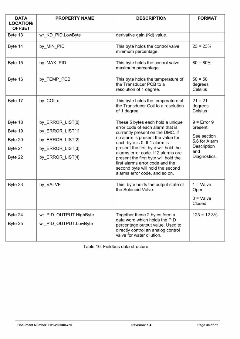
Byte 13 wr_KD_PID.LowByte derivative gain (Kd) value.
Byte 14 by_MIN_PID This byte holds the control valve minimum percentage.
23 = 23%
Byte 15 by_MAX_PID This byte holds the control valve maximum percentage.
80 = 80%
Byte 16 by_TEMP_PCB This byte holds the temperature of the Transducer PCB to a resolution of 1 degree.
50 = 50 degrees Celsius
Byte 17 by_COILc This byte holds the temperature of the Transducer Coil to a resolution of 1 degree.
21 = 21 degrees Celsius
Byte 18
Byte 19
Byte 20
Byte 21
Byte 22
by_ERROR_LIST[0]
by_ERROR_LIST[1]
by_ERROR_LIST[2]
by_ERROR_LIST[3]
by_ERROR_LIST[4]
These 5 bytes each hold a unique error code of each alarm that is currently present on the DMC. If no alarm is present the value for each byte is 0. If 1 alarm is present the first byte will hold the alarms error code. If 2 alarms are present the first byte will hold the first alarms error code and the second byte will hold the second alarms error code, and so on.
9 = Error 9 present.
See section 5.6 for Alarm Description and Diagnostics.
Byte 23 by_VALVE This byte holds the output state of the Solenoid Valve.
1 = Valve Open
0 = Valve Closed
Byte 24
Byte 25
wr_PID_OUTPUT.HighByte
wr_PID_OUTPUT.LowByte
Together these 2 bytes form a data word which holds the PID percentage output value. Used to directly control an analog control valve for water dilution.
123 = 12.3%
Table 10. Fieldbus data structure.
Document Number: F01-200000-750 Revision: 1.4 Page 39 of 52
4.2 Profibus DP
4.2.1 Profibus DP wiring
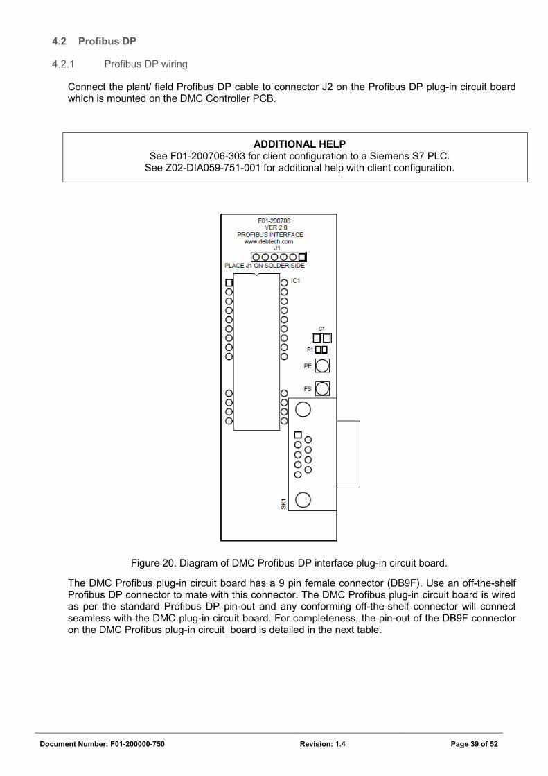
Connect the plant/ field Profibus DP cable to connector J2 on the Profibus DP plug-in circuit board which is mounted on the DMC Controller PCB.
ADDITIONAL HELP See F01-200706-303 for client configuration to a Siemens S7 PLC.
See Z02-DIA059-751-001 for additional help with client configuration.
Figure 20. Diagram of DMC Profibus DP interface plug-in circuit board.
The DMC Profibus plug-in circuit board has a 9 pin female connector (DB9F). Use an off-the-shelf Profibus DP connector to mate with this connector. The DMC Profibus plug-in circuit board is wired as per the standard Profibus DP pin-out and any conforming off-the-shelf connector will connect seamless with the DMC plug-in circuit board. For completeness, the pin-out of the DB9F connector on the DMC Profibus plug-in circuit board is detailed in the next table.
Document Number: F01-200000-750 Revision: 1.4 Page 40 of 52
PIN SIGNAL DESCRIPTION
1 - Not used
2 - Not used
3 B-Line Profibus B data line
4 RTS Ready to send
5 GND BUS Ground Bus, isolated
6 +5V BUS +5V output, isolated, 100mA max.
7 - Not used
8 A-Line Profibus A data line
Housing Shield Cable shield
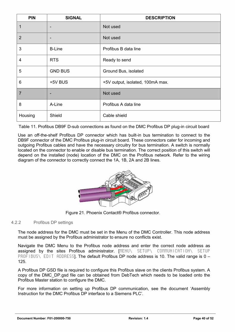
Table 11. Profibus DB9F D-sub connections as found on the DMC Profibus DP plug-in circuit board
Use an off-the-shelf Profibus DP connector which has built-in bus termination to connect to the DB9F connector of the DMC Profibus plug-in circuit board. These connectors cater for incoming and outgoing Profibus cables and have the necessary circuitry for bus termination. A switch is normally located on the connector to enable or disable bus termination. The correct position of this switch will depend on the installed (node) location of the DMC on the Profibus network. Refer to the wiring diagram of the connector to correctly connect the 1A, 1B, 2A and 2B lines.
Figure 21. Phoenix Contact® Profibus connector.
4.2.2 Profibus DP settings
The node address for the DMC must be set in the Menu of the DMC Controller. This node address must be assigned by the Profibus administrator to ensure no conflicts exist.
Navigate the DMC Menu to the Profibus node address and enter the correct node address as assigned by the sites Profibus administrator. [MENU\ SETUP\ COMMUNICATION\ SETUP PROFIBUS\ EDIT ADDRESS]. The default Profibus DP node address is 10. The valid range is 0 – 125.
A Profibus DP GSD file is required to configure this Profibus slave on the clients Profibus system. A copy of the DMC_DP.gsd file can be obtained from DebTech which needs to be loaded onto the Profibus Master station to configure the DMC.
For more information on setting up Profibus DP communication, see the document ‘Assembly Instruction for the DMC Profibus DP interface to a Siemens PLC’.
Document Number: F01-200000-750 Revision: 1.4 Page 41 of 52
4.3 Ethernet/IP and Modbus/TCP
4.3.1 Ethernet IP wiring
Ethernet/IP and Modbus/TCP are supported on the same plug-in circuit board. Connect the plants Ethernet/IP or ModBus/TCP RJ45 connector to the Ethernet connector J2 on the Ethernet IP plug-in circuit board which is mounted on the DMC Controller PCB. The setup of the DMC Controller is the same for both Ethernet/IP and Modbus/TCP applications. The configuration on the client side differs. This section will detail and test the interface using Ethernet/IP.
ADDITIONAL HELP See Z02-DIA062-751-001 for additional help with client configuration for Ethernet/IP.
See Z02-DIA062-751-002 for additional help with client configuration for Modbus/TCP.
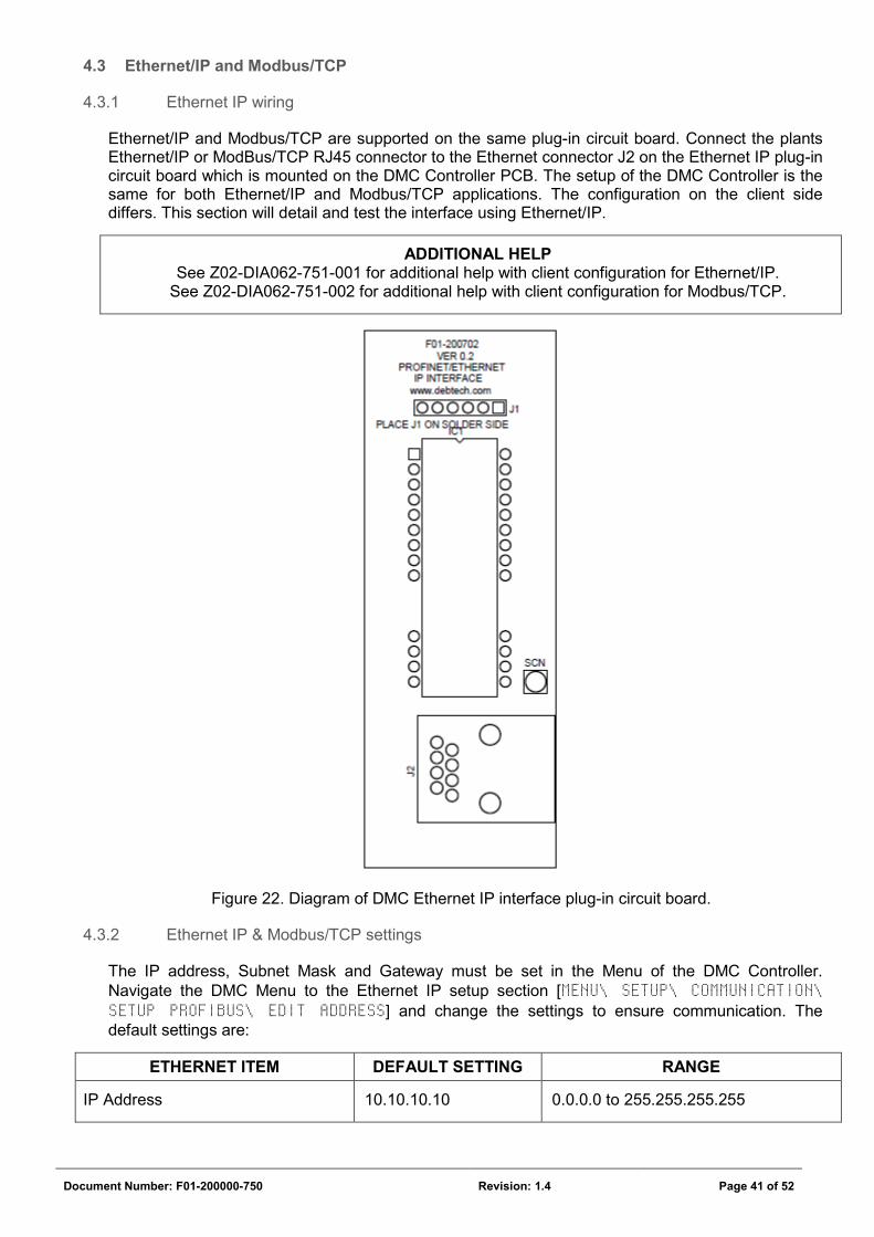
Figure 22. Diagram of DMC Ethernet IP interface plug-in circuit board.
4.3.2 Ethernet IP & Modbus/TCP settings
The IP address, Subnet Mask and Gateway must be set in the Menu of the DMC Controller. Navigate the DMC Menu to the Ethernet IP setup section [MENU\ SETUP\ COMMUNICATION\ SETUP PROFIBUS\ EDIT ADDRESS] and change the settings to ensure communication. The default settings are:
ETHERNET ITEM DEFAULT SETTING RANGE
IP Address 10.10.10.10 0.0.0.0 to 255.255.255.255
Document Number: F01-200000-750 Revision: 1.4 Page 42 of 52
ETHERNET ITEM DEFAULT SETTING RANGE
Subnet Mask 255.255.255.0 0.0.0.0 to 255.255.255.255
Gateway 0.0.0.0 0.0.0.0 to 255.255.255.255
DHCP Disabled (Cannot be changed)
Table 12. Ethernet settings.
The Ethernet settings can also be changed using the vendor program, Z02-DIA062-408, available from DebTech.
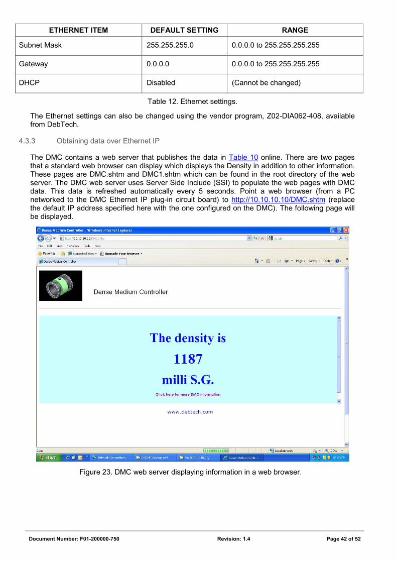
4.3.3 Obtaining data over Ethernet IP
The DMC contains a web server that publishes the data in Table 10 online. There are two pages that a standard web browser can display which displays the Density in addition to other information. These pages are DMC.shtm and DMC1.shtm which can be found in the root directory of the web server. The DMC web server uses Server Side Include (SSI) to populate the web pages with DMC data. This data is refreshed automatically every 5 seconds. Point a web browser (from a PC networked to the DMC Ethernet IP plug-in circuit board) to http://10.10.10.10/DMC.shtm (replace the default IP address specified here with the one configured on the DMC). The following page will be displayed.
Figure 23. DMC web server displaying information in a web browser.
Document Number: F01-200000-750 Revision: 1.4 Page 43 of 52
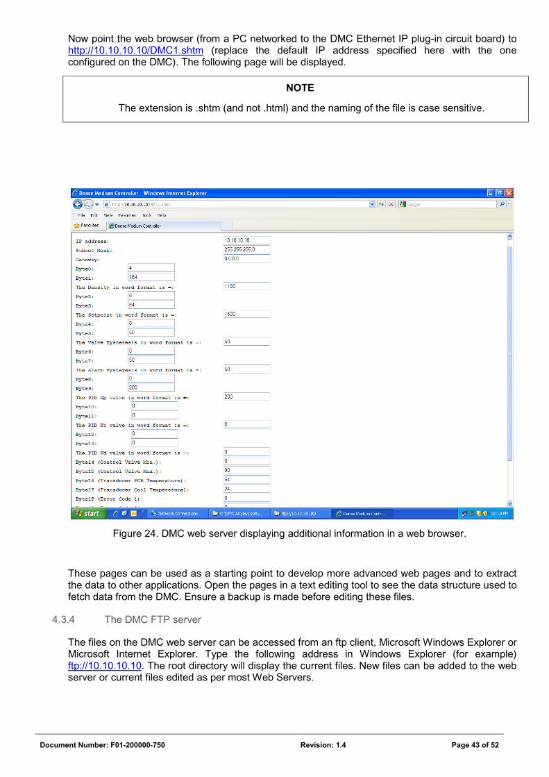
Now point the web browser (from a PC networked to the DMC Ethernet IP plug-in circuit board) to http://10.10.10.10/DMC1.shtm (replace the default IP address specified here with the one configured on the DMC). The following page will be displayed.
NOTE
The extension is .shtm (and not .html) and the naming of the file is case sensitive.
Figure 24. DMC web server displaying additional information in a web browser.
These pages can be used as a starting point to develop more advanced web pages and to extract the data to other applications. Open the pages in a text editing tool to see the data structure used to fetch data from the DMC. Ensure a backup is made before editing these files.
4.3.4 The DMC FTP server
The files on the DMC web server can be accessed from an ftp client, Microsoft Windows Explorer or Microsoft Internet Explorer. Type the following address in Windows Explorer (for example) ftp://10.10.10.10. The root directory will display the current files. New files can be added to the web server or current files edited as per most Web Servers.
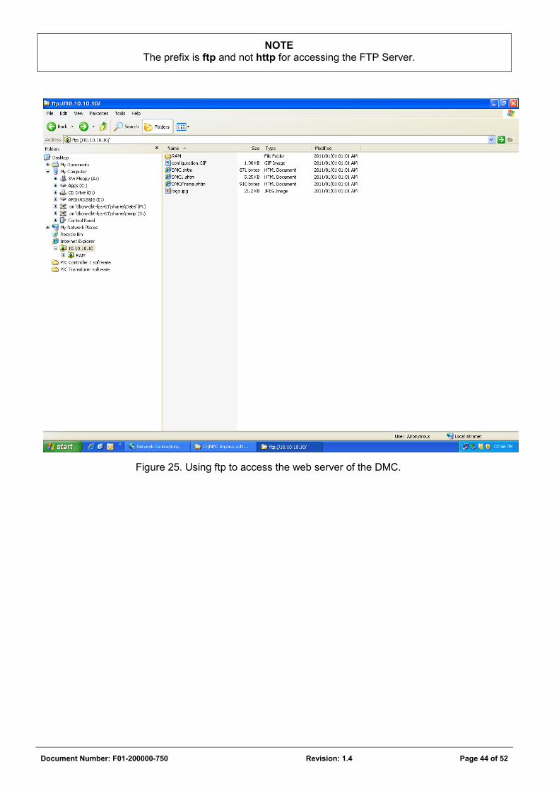
Document Number: F01-200000-750 Revision: 1.4 Page 44 of 52
NOTE The prefix is ftp and not http for accessing the FTP Server.
Figure 25. Using ftp to access the web server of the DMC.
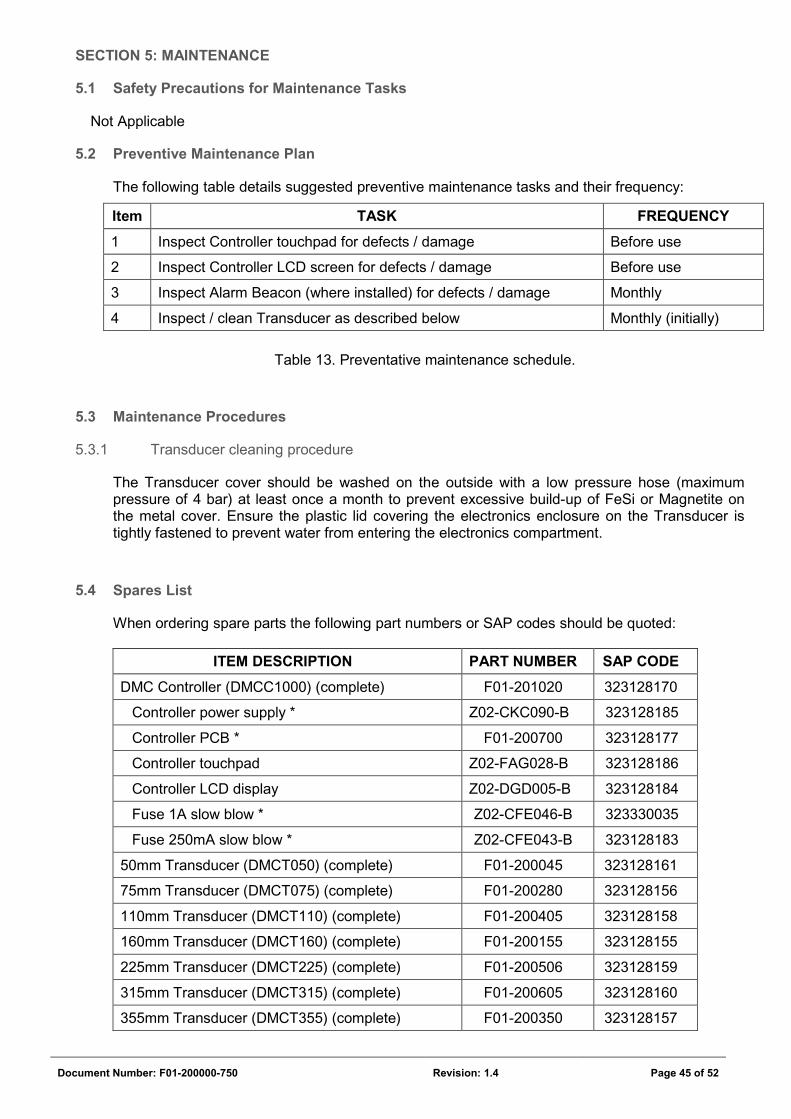
Document Number: F01-200000-750 Revision: 1.4 Page 45 of 52
SECTION 5: MAINTENANCE
5.1 Safety Precautions for Maintenance Tasks
Not Applicable
5.2 Preventive Maintenance Plan
The following table details suggested preventive maintenance tasks and their frequency:
Item TASK FREQUENCY
1 Inspect Controller touchpad for defects / damage Before use
2 Inspect Controller LCD screen for defects / damage Before use
3 Inspect Alarm Beacon (where installed) for defects / damage Monthly
4 Inspect / clean Transducer as described below Monthly (initially)
Table 13. Preventative maintenance schedule.
5.3 Maintenance Procedures
5.3.1 Transducer cleaning procedure
The Transducer cover should be washed on the outside with a low pressure hose (maximum pressure of 4 bar) at least once a month to prevent excessive build-up of FeSi or Magnetite on the metal cover. Ensure the plastic lid covering the electronics enclosure on the Transducer is tightly fastened to prevent water from entering the electronics compartment.
5.4 Spares List
When ordering spare parts the following part numbers or SAP codes should be quoted:
ITEM DESCRIPTION PART NUMBER SAP CODE
DMC Controller (DMCC1000) (complete) F01-201020 323128170
Controller power supply * Z02-CKC090-B 323128185
Controller PCB * F01-200700 323128177
Controller touchpad Z02-FAG028-B 323128186
Controller LCD display Z02-DGD005-B 323128184
Fuse 1A slow blow * Z02-CFE046-B 323330035
Fuse 250mA slow blow * Z02-CFE043-B 323128183
50mm Transducer (DMCT050) (complete) F01-200045 323128161
75mm Transducer (DMCT075) (complete) F01-200280 323128156
110mm Transducer (DMCT110) (complete) F01-200405 323128158
160mm Transducer (DMCT160) (complete) F01-200155 323128155
225mm Transducer (DMCT225) (complete) F01-200506 323128159
315mm Transducer (DMCT315) (complete) F01-200605 323128160
355mm Transducer (DMCT355) (complete) F01-200350 323128157
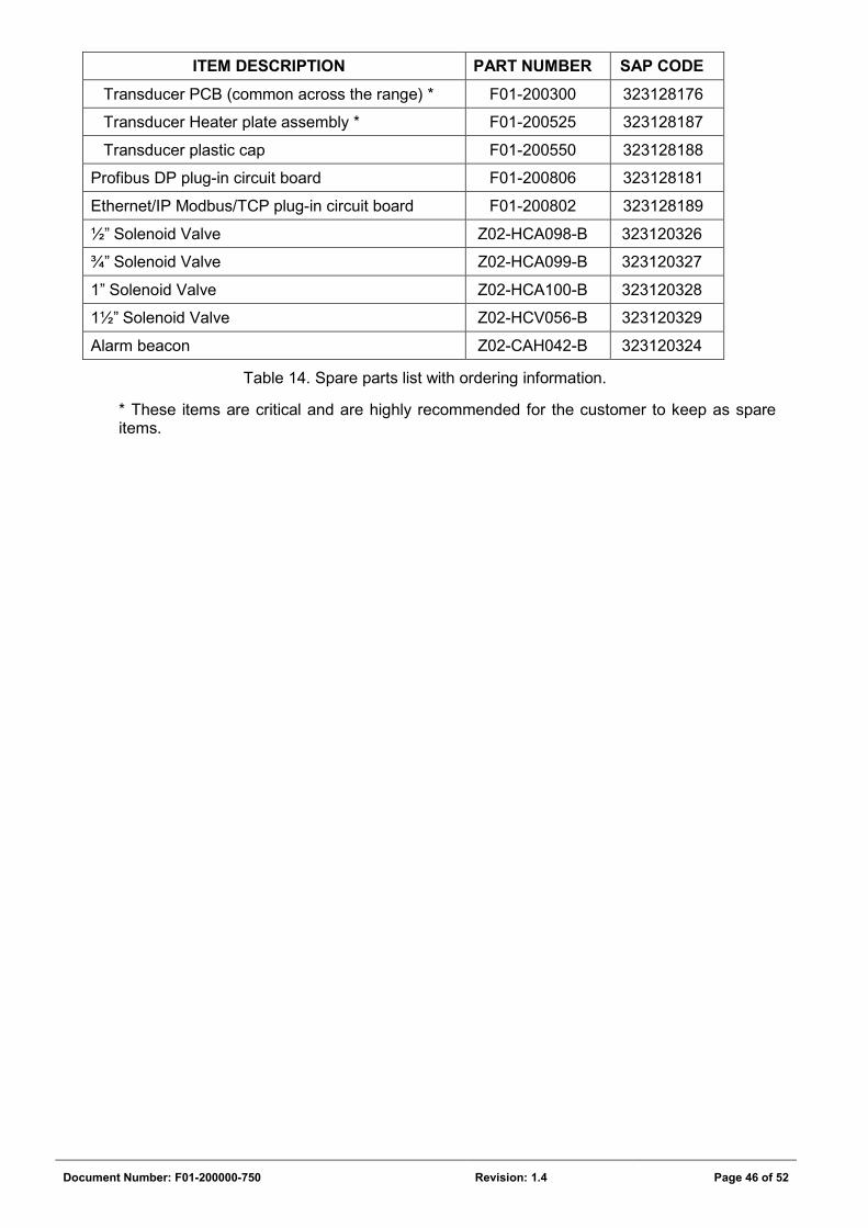
Document Number: F01-200000-750 Revision: 1.4 Page 46 of 52
ITEM DESCRIPTION PART NUMBER SAP CODE
Transducer PCB (common across the range) * F01-200300 323128176
Transducer Heater plate assembly * F01-200525 323128187
Transducer plastic cap F01-200550 323128188
Profibus DP plug-in circuit board F01-200806 323128181
Ethernet/IP Modbus/TCP plug-in circuit board F01-200802 323128189
½” Solenoid Valve Z02-HCA098-B 323120326
¾” Solenoid Valve Z02-HCA099-B 323120327
1” Solenoid Valve Z02-HCA100-B 323120328
1½” Solenoid Valve Z02-HCV056-B 323120329
Alarm beacon Z02-CAH042-B 323120324
Table 14. Spare parts list with ordering information.
* These items are critical and are highly recommended for the customer to keep as spare items.
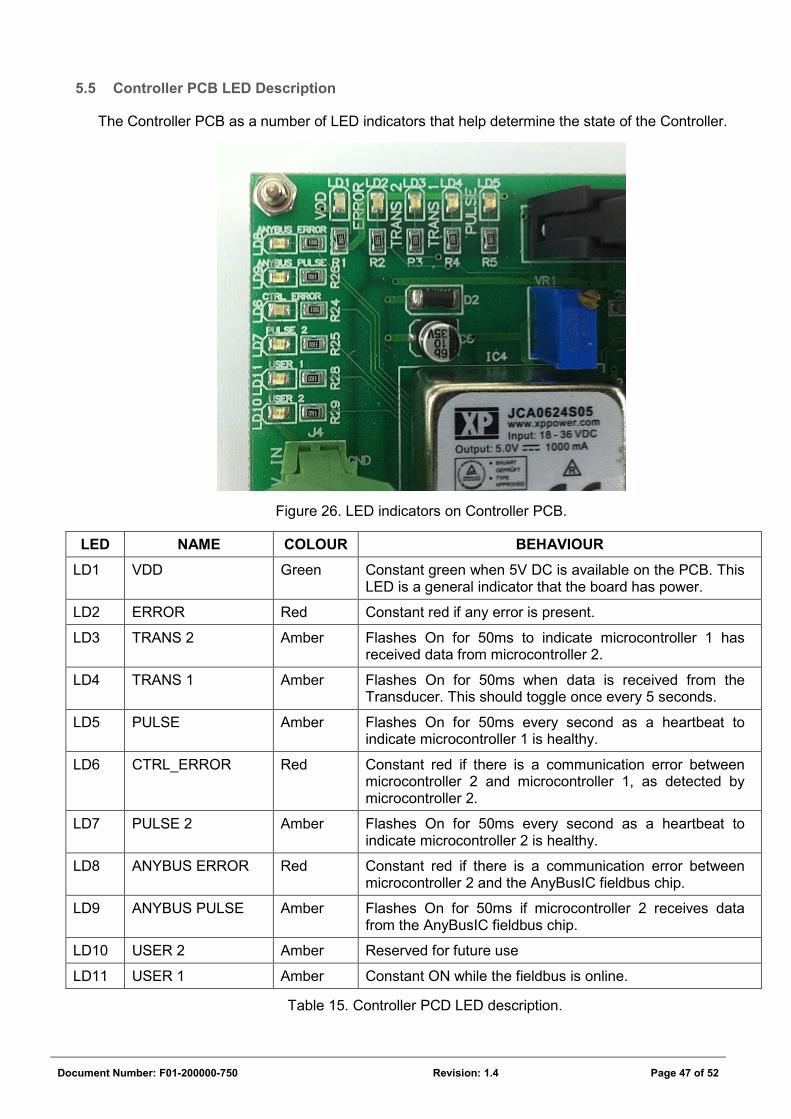
Document Number: F01-200000-750 Revision: 1.4 Page 47 of 52
5.5 Controller PCB LED Description
The Controller PCB as a number of LED indicators that help determine the state of the Controller.
Figure 26. LED indicators on Controller PCB.
LED NAME COLOUR BEHAVIOUR LD1 VDD Green Constant green when 5V DC is available on the PCB. This
LED is a general indicator that the board has power.
LD2 ERROR Red Constant red if any error is present.
LD3 TRANS 2 Amber Flashes On for 50ms to indicate microcontroller 1 has received data from microcontroller 2.
LD4 TRANS 1 Amber Flashes On for 50ms when data is received from the Transducer. This should toggle once every 5 seconds.
LD5 PULSE Amber Flashes On for 50ms every second as a heartbeat to indicate microcontroller 1 is healthy.
LD6 CTRL_ERROR Red Constant red if there is a communication error between microcontroller 2 and microcontroller 1, as detected by microcontroller 2.
LD7 PULSE 2 Amber Flashes On for 50ms every second as a heartbeat to indicate microcontroller 2 is healthy.
LD8 ANYBUS ERROR Red Constant red if there is a communication error between microcontroller 2 and the AnyBusIC fieldbus chip.
LD9 ANYBUS PULSE Amber Flashes On for 50ms if microcontroller 2 receives data from the AnyBusIC fieldbus chip.
LD10 USER 2 Amber Reserved for future use
LD11 USER 1 Amber Constant ON while the fieldbus is online.
Table 15. Controller PCD LED description.
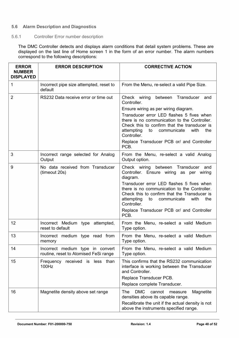
Document Number: F01-200000-750 Revision: 1.4 Page 48 of 52
5.6 Alarm Description and Diagnostics
5.6.1 Controller Error number description
The DMC Controller detects and displays alarm conditions that detail system problems. These are displayed on the last line of Home screen 1 in the form of an error number. The alarm numbers correspond to the following descriptions:
ERROR NUMBER
DISPLAYED
ERROR DESCRIPTION CORRECTIVE ACTION
1 Incorrect pipe size attempted, reset to default
From the Menu, re-select a valid Pipe Size.
2 RS232 Data receive error or time out Check wiring between Transducer and Controller.
Ensure wiring as per wiring diagram.
Transducer error LED flashes 5 fives when there is no communication to the Controller. Check this to confirm that the transducer is attempting to communicate with the Controller.
Replace Transducer PCB or/ and Controller PCB.
3 Incorrect range selected for Analog Output
From the Menu, re-select a valid Analog Output option.
9 No data received from Transducer (timeout 20s)
Check wiring between Transducer and Controller. Ensure wiring as per wiring diagram.
Transducer error LED flashes 5 fives when there is no communication to the Controller. Check this to confirm that the Transducer is attempting to communicate with the Controller.
Replace Transducer PCB or/ and Controller PCB.
12 Incorrect Medium type attempted, reset to default
From the Menu, re-select a valid Medium Type option.
13 Incorrect medium type read from memory
From the Menu, re-select a valid Medium Type option.
14 Incorrect medium type in convert routine, reset to Atomised FeSi range
From the Menu, re-select a valid Medium Type option.
15 Frequency received is less than 100Hz
This confirms that the RS232 communication interface is working between the Transducer and Controller.
Replace Transducer PCB.
Replace complete Transducer.
16 Magnetite density above set range The DMC cannot measure Magnetite densities above its capable range.
Recalibrate the unit if the actual density is not above the instruments specified range.
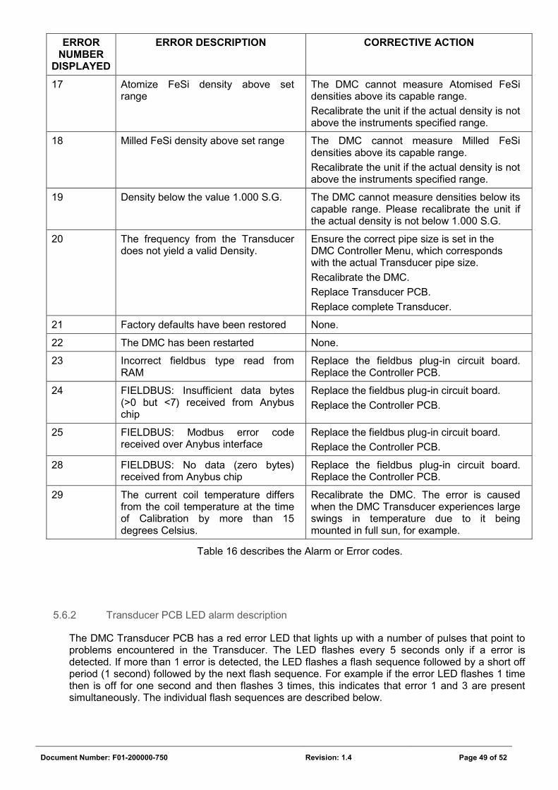
Document Number: F01-200000-750 Revision: 1.4 Page 49 of 52
ERROR NUMBER
DISPLAYED
ERROR DESCRIPTION CORRECTIVE ACTION
17 Atomize FeSi density above set range
The DMC cannot measure Atomised FeSi densities above its capable range.
Recalibrate the unit if the actual density is not above the instruments specified range.
18 Milled FeSi density above set range The DMC cannot measure Milled FeSi densities above its capable range.
Recalibrate the unit if the actual density is not above the instruments specified range.
19 Density below the value 1.000 S.G. The DMC cannot measure densities below its capable range. Please recalibrate the unit if the actual density is not below 1.000 S.G.
20 The frequency from the Transducer does not yield a valid Density.
Ensure the correct pipe size is set in the DMC Controller Menu, which corresponds with the actual Transducer pipe size.
Recalibrate the DMC.
Replace Transducer PCB.
Replace complete Transducer.
21 Factory defaults have been restored None.
22 The DMC has been restarted None.
23 Incorrect fieldbus type read from RAM
Replace the fieldbus plug-in circuit board. Replace the Controller PCB.
24 FIELDBUS: Insufficient data bytes (>0 but <7) received from Anybus chip
Replace the fieldbus plug-in circuit board.
Replace the Controller PCB.
25 FIELDBUS: Modbus error code received over Anybus interface
Replace the fieldbus plug-in circuit board.
Replace the Controller PCB.
28 FIELDBUS: No data (zero bytes) received from Anybus chip
Replace the fieldbus plug-in circuit board. Replace the Controller PCB.
29 The current coil temperature differs from the coil temperature at the time of Calibration by more than 15 degrees Celsius.
Recalibrate the DMC. The error is caused when the DMC Transducer experiences large swings in temperature due to it being mounted in full sun, for example.
Table 16 describes the Alarm or Error codes.
5.6.2 Transducer PCB LED alarm description
The DMC Transducer PCB has a red error LED that lights up with a number of pulses that point to problems encountered in the Transducer. The LED flashes every 5 seconds only if a error is detected. If more than 1 error is detected, the LED flashes a flash sequence followed by a short off period (1 second) followed by the next flash sequence. For example if the error LED flashes 1 time then is off for one second and then flashes 3 times, this indicates that error 1 and 3 are present simultaneously. The individual flash sequences are described below.
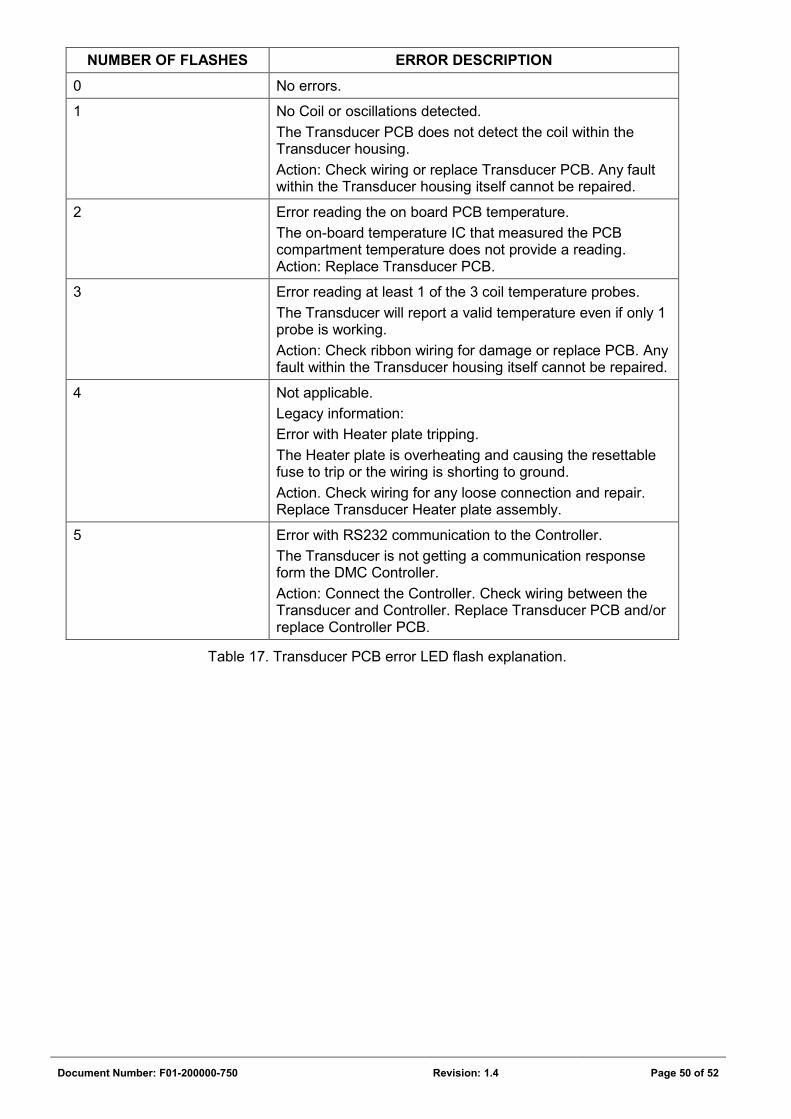
Document Number: F01-200000-750 Revision: 1.4 Page 50 of 52
NUMBER OF FLASHES ERROR DESCRIPTION
0 No errors.
1 No Coil or oscillations detected.
The Transducer PCB does not detect the coil within the Transducer housing.
Action: Check wiring or replace Transducer PCB. Any fault within the Transducer housing itself cannot be repaired.
2 Error reading the on board PCB temperature.
The on-board temperature IC that measured the PCB compartment temperature does not provide a reading. Action: Replace Transducer PCB.
3 Error reading at least 1 of the 3 coil temperature probes.
The Transducer will report a valid temperature even if only 1 probe is working.
Action: Check ribbon wiring for damage or replace PCB. Any fault within the Transducer housing itself cannot be repaired.
4 Not applicable.
Legacy information:
Error with Heater plate tripping.
The Heater plate is overheating and causing the resettable fuse to trip or the wiring is shorting to ground.
Action. Check wiring for any loose connection and repair. Replace Transducer Heater plate assembly.
5 Error with RS232 communication to the Controller.
The Transducer is not getting a communication response form the DMC Controller.
Action: Connect the Controller. Check wiring between the Transducer and Controller. Replace Transducer PCB and/or replace Controller PCB.
Table 17. Transducer PCB error LED flash explanation.
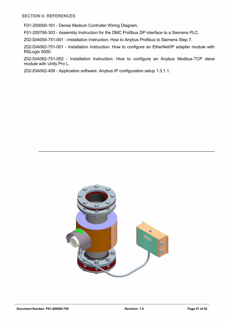
Document Number: F01-200000-750 Revision: 1.4 Page 51 of 52
SECTION 6: REFERENCES
F01-200000-161 - Dense Medium Controller Wiring Diagram.
F01-200706-303 - Assembly Instruction for the DMC Profibus DP interface to a Siemens PLC.
Z02-DIA059-751-001 - Installation Instruction: How to Anybus Profibus to Siemens Step 7.
Z02-DIA062-751-001 - Installation Instruction: How to configure an EtherNet/IP adapter module with RSLogix 5000.
Z02-DIA062-751-002 - Installation Instruction: How to configure an Anybus Modbus-TCP slave module with Unity Pro L.
Z02-DIA062-408 - Application software: Anybus IP configuration setup 1.3.1.1.
___________________________________________________________________________
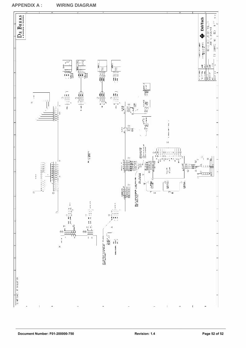
Document Number: F01-200000-750 Revision: 1.4 Page 52 of 52
APPENDIX A : WIRING DIAGRAM