Embed Size (px)
Citation preview

419903 02.27.08 BY Printed in U.S.A.
Para pedir servicio de reparación
a domicilio, y para ordenar piezas:
1-888-SU-HOGAR®
(1-888-784-6427)
AuCanada pour service en français:
1-800-LE-FOYERMC
(1-800-533-6937)
www.sears.ca
To purchase a protection agreement (U.S.A.)
or maintenance agreement (Canada) on a product serviced by Sears:
1-800-827-6655 (U.S.A.) 1-800-361-6665 (Canada)
Our Home
For repair of carry-in products like vacuums, lawn equipment,
and electronics, call or go on-line for the nearest
Sears Parts and Repair Center.
1-800-488-1222 Anytime, day or night (U.S.A. only)
www.sears.com
Your Home
For repair – in your home – of all major brand appliances,
lawn and garden equipment, or heating and cooling systems,
no matter who made it, no matter who sold it!
For the replacement parts, accessories and
owner’s manuals that you need to do-it-yourself.
For Sears professional installation of home appliances
and items like garage door openers and water heaters.
1-800-4-MY-HOME® Anytime, day or night
(1-800-469-4663) (U.S.A. and Canada)
www.sears.com www.sears.ca
Get it fixed, at your home or ours!
©SearsBrands,LLC
® Registered Trademark /TMTrademark /
SMService Mark of Sears Brands, LLC
® Marca Registrada /TMMarca de Fábrica /
SMMarca de Servicio de Sears Brands, LLC
MCMarque de commerce /
MDMarque déposée de Sears Brands, LLC
CAUTION:Read and follow all Safety Rules and In struc tions before operating this equipment
Owner’s Manual
Sears, Roebuck and Co., Hoffman Estates, IL 60179 U.S.A.Visit our Craftsman website: www.sears.com/craftsman
Model No.917.374456
ROTARY LAWN MOWER875 Series Briggs & Stratton EnginePower-Propelled21" Multi-Cut

2
Safe ty Rules ..........................................2-3Warranty ...................................................4Prod uct Spec i fi ca tions ..............................5Assembly / Pre-Operation ........................6Op er a tion.............................................7-11Maintenance Sched ule ...........................12
Maintenance......................................12-15Ser vice and Ad just ments...................15-16Stor age..............................................17-18Trou ble shoot ing.................................18-19Re pair Parts.......................................38-46
TABLE OF CONTENTS
IMPORTANT: This cutting machine is capable of amputating hands and feet and throwing ob-jects. Failure to observe the following safety instructions could result in serious injury or death.
Look for this symbol to point out im- por tant safety precautions. It meansCAU TION!!! BECOME ALERT!!!YOUR SAFE TY IS INVOLVED.
WARNING: In order to prevent ac ci den tal starting when setting up, trans port ing, ad- just ing or making repairs, always dis con nect spark plug wire and place wire where it can not come in contact with plug.
WARNING: Engine exhaust, some of its constituents, and certain vehicle com po -nents contain or emit chem i cals known to the State of Cal i for nia to cause can cer and birth defects or oth er re pro duc tive harm.
WARNING: Battery posts, terminals and related accessories contain lead and lead compounds, chemicals known to the State of Cal i for nia to cause can cer and birth defects or oth er re pro duc tive harm. Wash hands after handling.
CAUTION: Muffl er and other engine
SAFETY RULES
parts become extremelyhot during operation and remain hot after enginehas stopped. To avoid severe burns on contact, stay away from these areas.
I. GENERAL OPERATION• Read, understand, and follow all
in struc tions on the machine and in the manual(s) before starting. Be thor ough ly familiar with the controls and the proper use of the machine before starting.
• Do not put hands or feet near or under rotating parts. Keep clear of the dis- charge opening at all times.
• Only allow responsible individuals, who are familiar with the in struc tions, to operate the machine.
• Clear the area of objects such as rocks, toys, wire, bones, sticks, etc., which could be picked up and thrown by blade.
• Be sure the area is clear of other people before mowing. Stop the ma chine if anyone enters the area.
• Do not operate the mower when bare- foot or wearing open sandals. Al ways wear substantial foot wear.
• Do not pull mower backwards unless abso-lutely nec es sary. Always look down and be-hind before and while moving backwards.
• Never direct discharged material toward anyone. Avoid discharging material against a wall or obstruction. Material may richochet back toward the operator. Stop the blade when crossing gravel surfaces.
• Do not operate the mower without prop-er guards, plates, grass catcher or oth er safety protective devices in place.
• See manufacturer’s instructions for proper operation and installation of accessories. Only use accessories ap-proved by the manufacturer.
• Stop the blade(s) when crossing grav el drives, walks, or roads.
• Stop the engine (motor) whenever you leave the equip ment, before clean ing the mower or unclogging the chute.
• Shut the engine (motor) off and wait until the blade comes to complete stop before removing grass catcher.
• Mow only in daylight or good artifi cial light.• Do not operate the machine while under
the infl uence of alcohol or drugs.• Never operate machine in wet grass.
Always be sure of your footing: keep a fi rm hold on the handle; walk, never run.
• Disengage the self-propelled mech- a nism or drive clutch on mowers so equipped before starting the engine.
• If the equipment should start to vi brate abnormally, stop the engine (motor) and check immediately for the cause. Vibra-tion is generally a warning of trouble.
• Always wear safety goggles or safe ty glass-es with side shields when op er at ing mower.
II. SLOPE OPERATIONSlopes are a major factor related to slip & fall accidents which can result in severe injury. All slopes require extra caution. If you feel uneasy on a slope, do not mow it. 47
Engine Power Rating Information
The gross power rating for individual gas engine models is labeled in accordance with SAE (So-ciety of Automo-tive Engineers) code J11940 (Small Engine Power & Torque Rating Procedure), and rating performance has been obtained and corrected in accordance with SAE J1995 (Revision 2002-5). Actual gross engine power will be lower and is affected by, among other things, ambi-ent operating conditions and engine-to-engine variability. Given both the wide array of products on which engines are placed and the variety of environmental issues applicable to operating the equipment, the gas engine will not develop the rated gross power when used in a given piece of power equipment (actual “on-site” or net horsepower). This difference is due to a variety of factors including, but not limited to, accessories (air cleaner, exhaust, charging, cooling, carburetor, fuel pump, etc.), application limitations, ambient operating conditions (temperature, humidity, altitude), and engine-to-engine variability. Due to manufacturing and capacity limitations, Briggs & Stratton may substitute an engine of higher rated power for this Series engine.

46
MODEL NUMBER 128602-1102-E1BRIGGS & STRATTON 4-CYCLE ENGINE
KEY PARTNO. NO. DESCRIPTION
445 697029 Filter, Air Cleaner Cartridge455 791960 Cup-Flywheel456 692299 Plate-Pawl Friction459 281505s Pawl-Ratchet505 691251 Nut (Governor Control Lever)523 499621 Dipstick524 692296 • Seal-Dipstick Tube525 495265 Tube-Dipstick562 92613 Bolt (Governor Control Lever)584 697734 Cover-Breather Passage585 691879 • Gasket-Breather Passage592 690800 Nut (Rewind Starter)597 691696 Screw (Pawl Friction Plate)601 791850 Clamp-Hose608 497680 Starter-Rewind613 691108 Screw (Muffl er)613A 691140 Screw (Muffl er)615 690340 Retainer-Governor Shaft616 698801 Crank-Governor619 691108 Screw (Cylinder Head Plate)621 692310 Switch-Stop633 691321 ؇ Seal-Throttle Shaft635 66538s Boot-Spark Plug670 692294 Spacer-Fuel Tank684 690345 Screw (Breather Passage Cover)689 691855 Spring-Friction718 690959 Pin-Locating741 794388 Gear-Timing745 691648 Screw (Brake)830 694544 Stud (Rocker Arm)842 691031 • Seal-O Ring (Dipstick Tube)847 692047 Assembly-Dipstick/Tube851 493880s Terminal-Spark Plug868 795440 •+ Seal-Valve883 691893 •+ Gasket-Exhaust886 696268 Gasket Kit, Cylinder Head/Plate914 691108 Screw (Rocker Cover)914A 691127 Screw (Rocker Cover)921 691465 Cover-Blower Housing922 692135 Spring-Brake923 695891 Brake
KEY PARTNO. NO. DESCRIPTION
957 793606 Cap-Fuel Tank966 690243 Base-Air Cleaner Primer967 273356s Filter-Pre Cleaner968 691342 Cover-Air Cleaner969 691138 Screw (Blower Housing Cover)972 699374 Tank-Fuel975 493640 Bowl-Float976 694395 Primer-Carburetor977 792385 Set-Carburetor Gasket993 694088 •+ Gasket, Cylinder Head Plate1022 691890 •+ Gasket-Rocker Cover1023 499624 Cover-Rocker Arm1026 795444 Rod-Push1029 691230 Arm-Rocker1034 691343 Guide-Push Rod1036 - - - Label-Emissions (Available from an authorized Briggs & Stratton Service Dealer)1058 277102TRI Operator’s Manual1059 692311 Kit-Screw/Washer1095 792386 Set-Valve Gasket1210 498144 Assembly-Pulley/Spring (Pulley)1211 498144 Assembly-Pulley/Spring (Spring)1329 12S502-0025 Replacement Engine (Replacement engine listed is not available in the State of California. Repair with individual parts.)1330 272147 Repair Manual
- - 398067 Spark Arrester (available accessory)
• Included in Engine Gasket Set, Key No. 358
Ø Included in Carb. Overhaul Kit, Key No. 121
‡ Included in Carb. Gasket Set, Key No. 977
+ Included in Valve Gasket Set, Key No. 1095
NOTE: All component dimensions given in U.S. inches. 1 inch = 25.4 mm
3
DO:• Mow across the face of slopes: nev er
up and down. Exercise extreme caution when changing direction on slopes.
• Remove obstacles such as rocks, tree limbs, etc.
• Watch for holes, ruts, or bumps. Tall grass can hide obstacles.
DO NOT:• Do not trim near drop-offs, ditches or
embankments. The operator could lose footing or balance.
• Do not trim excessively steep slopes.• Do not mow on wet grass. Reduced
footing could cause slipping.
III. CHILDRENTragic accidents can occur if the op er a tor is not alert to the presence of children. Children are often attracted to the ma chine and the mowing activity. Never assume that children will remain where you last saw them.• Keep children out of the trimming area
and under the watchful care of an oth er re spon si ble adult.
• Be alert and turn machine off if chil dren enter the area.
• Before and while walking back wards, look behind and down for small chil dren.
• Never allow children to operate machine.• Use extra care when approaching blind
corners, shrubs, trees, or other objects that may obscure vision.
IV. SAFE HANDLING OF GASOLINEUse extreme care in handling gasoline. Gasoline is extremely fl ammable and the vapors are explosive.• Extinguish all cigarettes, cigars, pipes
and other sources of ignition.• Use only an approved container.• Never remove gas cap or add fuel with
the engine running. Allow engine to cool before refueling.
• Never refuel the machine indoors.• Never store the machine or fuel contain-
er where there is an open fl ame, spark or pilot light such as a water heater or on other appliances.
• Never fi ll containers inside a vehicle, on a truck or trailer bed with a plastic liner. Always place containers on the ground away from your vehicle before fi lling.
• Remove gas-powered equipment from the truck or trailer and refuel it on the ground. If this is not possible, then refuel such equip-ment with a portable container, rather than from a gasoline dispenser nozzle.
• Keep the nozzle in contact with the rim of the fuel tank or container opening at all times until fueling is complete. Do not use a nozzle lock-open device.
• If fuel is spilled on clothing, change clothing immediately.
• Never overfi ll fuel tank. Replace gas cap and tighten securely.
V. GENERAL SERVICE• Never run machine inside a closed area.• Never make adjustments or repairs with
the engine (motor) running. Dis con nect the spark plug wire, and keep the wire away from the plug to prevent ac ci den tal starting.
• Keep nuts and bolts, especially blade attachment bolts, tight and keep equip-ment in good condition.
• Never tamper with safety devices. Check their proper operation reg u lar ly.
• Keep machine free of grass, leaves, or other debris build-up. Clean oil or fuel spill-age. Allow machine to cool before storing.
• Stop and inspect the equipment if you strike an object. Repair, if nec es sary, before restarting.
• Never attempt to make wheel height adjustments while the engine is running.
• Grass catcher components are sub ject to wear, dam age, and de te ri o ra tion, which could expose moving parts or allow objects to be thrown. Frequently check com po -nents and replace with man u fac tur er’s recommended parts, when necessary.
• Mower blades are sharp and can cut. Wrap the blade(s) or wear gloves, and use extra caution when ser vic ing them.
• Do not change the engine governor set-ting or overspeed the engine.
• Maintain or replace safety and instruc-tion labels, as necessary.
WARNING: This lawn mower is equipped with an internal com bus tion engine and should not be used on or near any un im proved forest-covered, brush-covered or grass-cov ered land unless the engine’s exhaust system is equipped with a spark arrester meeting applicable local or state laws (if any). If a spark arrester is used, it should be maintained in effective working order by the operator.In the state of California the above is required by law (Section 4442 of the California Public Resources Code). Other states may have similar laws. Federal laws apply on federal lands. A spark arrester for the muffl er is available through your nearest Husqvarna or other authorized service center (See the REPAIR PARTS section of this manual).

4
WARRANTYSECTION 1: LIMITED WARRANTYHusqvarna Forest & Garden Company (“Husqvarna”) warrants Husqvarna product to the original purchaser to be free from defects in material and workmanship from the date of purchase for the “Warranty Period” of the product as set forth below:
2 YEAR NON-COMMERCIAL WARRANTY: Auto-matic Mower, Riding lawn mowers, yard and garden tractors, walk behind mowers, tillers, chain saws, trimmers, brushcutters, clearing saws, snow blowers, handheld blowers, backpack blowers, hedge trimmers, electrical products and power-assist collection systems for non com mer cial, nonprofessional, noninstitutional or nonincome producing use, except as herein stated.
Emission control system components necessary to comply with CARB-TIER-II and EPA regulations.
Husqvarna Safety Apparel carries a 90-day warranty from the date of the customer’s original purchase for defects in material and workmanship. Normal wear, tear or abuse is not covered under warranty. Product must be returned to Charlotte with a warranty claim form. All care and maintenance instructions must be followed as stated by the manufacturer on the care label. The fi t of the protective apparel/boot is not covered under warranty.
SECTION 2: HUSQVARNA’S OBLIGATIONS UNDER THE WARRANTYHusqvarna will repair or replace defective components without charge for parts or labor if a component fails because of a defect in material or workmanship during the warranty period.
SECTION 3: ITEMS NOT COVERED BY THIS WAR-RANTYThe following items are not covered by this warranty:(1)Normal customer maintenance items which become
worn through normal regular use, including, but not limited to, belts, blades, blade adapters, bulbs, fi lters, guide bars, lubricants, rewind springs, saw chain, spark plugs, starter ropes and tines;
(2) Natural discoloration of material due to ultraviolet light;
(3) Lawn and garden attachments are covered by a third party which gives a warranty, all claims for warranty should be sent to the manufacturer; and
(4)Emission Control System components necessary to which are manufactured by third party engine manufacturer.
SECTION 4: EXCEPTIONS AND LIMITATIONSThis warranty shall be inapplicable to defects resulting from the following:(1) Accident, abuse, misuse, negligence and neglect,
including stale fuel, dirt, abrasives, moisture, rust, corrosion, or any adverse reaction due to incorrect storage or use habits;
(2) Failure to operate or maintain the unit in accor-dance with the Owner’s/Operator’s manual or instruction sheet furnished by Husqvarna;
(3) Alterations or modifi cations that change the intended use of the product or affects the product’s performance, operation, safety, or durability, or causes the product to fail to comply with any ap-plicable laws; or:
(4) Additional damage to parts or components due to continued use occurring after any of the above.
REPAIR OR REPLACEMENT AS PROVIDED UNDER THIS WARRANTY IS THE EXCLUSIVE REMEDY OF THE PUR CHAS ER. HUSQVARNA SHALL NOT BE LIABLE FOR ANY INCIDENTAL OR CONSEQUEN-TIAL DAMAGES FOR BREACH OF ANY EXPRESS OR IMPLIED WARRANTY ON THESE PRODUCTS EXCEPT TO THE EXTENT PROHIBITED BY AP-PLICABLE LAW. ANY IMPLIED WARRANTY OF MERCHANTABILITY OR FITNESS FOR A PARTICU-LAR PURPOSE ON THESE PRODUCTS IS LIMITED IN DURATION TO THE WARRANTY PERIOD AS DEFINED IN THE LIMITED WARRANTY STATE-MENT. HUSQVARNA RE SERVES THE RIGHT TO CHANGE OR IMPROVE THE DESIGN OF THE PRODUCT WITHOUT NO TICE, AND DOES NOT ASSUME OBLIGATION TO UPDATE PREVIOUSLY MANUFACTURED PROD UCTS.
Some states do not allow the exclusion of incidental or consequential damages, or limitations on how long an implied warranty lasts, so the above limitations or exclusions may not apply to you. This warranty gives you specifi c legal rights, and you may also have other rights which vary from state to state.
SECTION 5: CUSTOMER RESPONSIBILITIESThe product must exhibit reasonable care, mainte-nance, operation, storage and general upkeep as written in the maintenance section of the Owner’s/Operator’s manual. Should an operational problem or failure occur, the product should not be used, but delivered as is to an authorized Husqvarna dealer for evaluation. Proof of purchase, as explained in section 6, rests solely with the customer.
SECTION 6: PROCEDURE TO OBTAIN WARRANTY CONSIDERATIONIt is the Owner’s and Dealer’s responsibility to make certain that the Warranty Registration Card is properly fi lled out and mailed to Husqvarna Forest & Garden Company. This card should be mailed within ten (10) days from the date of purchase in order to confi rm the warranty and to facilitate post-sale service.
Proof of purchase must be presented to the authorized Husqvarna dealer in order to obtain warranty service. This proof must include date purchased, model num-ber, serial number, and complete name and address of the selling dealer.
To obtain the benefi t of this warranty, the product believed to be defective must be delivered to an authorized Husqvarna dealer in a timely manner, no later than thirty (30) days from date of the operational problem or failure. The product must be delivered at the owner’s expense. Pick-up and delivery charges are not covered by this warranty. An authorized Husqvarna dealer can be normally located through the “Yellow Pages” of the local telephone directory or by calling 1-800-HUSKY62 for a dealer in your area.
HUSQVARNA 7349 Statesville RoadCharlotte, NC 28269531 83 81-23 2002
45
MODEL NUMBER 128602-1102-E1BRIGGS & STRATTON 4-CYCLE ENGINE
KEY PARTNO. NO. DESCRIPTION
1 692670 Cylinder Assembly2 399269 Kit-Bushing/Seal3 299819s • Seal-Oil (Magneto Side)4 493279 Sump-Engine5 792381 Head-Cylinder7 697230 •+ Gasket-Cylinder Head8 495786 Breather Assembly9 699833 • Gasket-Breather10 691125 Screw (Breather Assembly)11 691781 Tube-Breather11A 692937 Tube-Breather12 692232 • Gasket-Crankcase13 691137 Screw (Cylinder Head)15 691680 Plug-Oil Drain16 691456 Crankshaft 20 399781s • Seal-Oil (PTO Side)22 691092 Screw (Engine Sump)23 697610 Flywheel24 222698s Key-Flywheel25 795429 Piston Assembly (Standard Size) 795430 Piston Assembly (.020" Oversize)26 795431 Ring Set (Standard) 795432 Ring Set (.020" Oversize)27 691866 Lock-Piston Pin28 499423 Pin-Piston29 499424 Rod-Connecting32 691664 Screw (Connecting Rod)32A 695759 Screw (Connecting Rod)33 499642 Valve-Exhaust34 499641 Valve-Intake35 691304 Spring-Valve (Intake)36 691304 Spring-Valve (Exhaust)37 793756 Guard-Flywheel40 692194 Retainer-Valve43 691997 Slinger-Governor/Oil45 690977 Tappet-Valve46 694039 Camshaft48 692748 Short Block 51 692668 • ؇+ Gasket-Intake51A 692555 •Ø‡+ Gasket-Intake51B 697735 •Ø‡+ Gasket-Intake55 691421 Housing-Rewind Starter58 697316 Rope-Starter (Cut to Required Length)60 281434s Grip-Starter Rope
KEY PARTNO. NO. DESCRIPTION
65 690837 Screw (Rewind Starter)78 691108 Screw (Flywheel Guard)95 691636 Screw (Throttle Valve)97 790121 Shaft-Throttle104 691242 Ø Pin-Float Hinge117 498981 Jet-Main (Standard)118 498978 Jet-Main (High Altitude)121 792383 Kit-Carburetor Overhaul122 792382 Spacer-Carburetor125 790120 Carburetor127 694468 Ø Plug-Welch130 696564 Valve-Throttle133 398187 Float-Carburetor134 398188 Ø Valve-Needle/Seat 137 693981 ؇ Gasket-Float Bowl163 691894 •Ø‡+ Gasket-Air Cleaner187 791766 Line-Fuel (Cut to Required Length)188 691147 Screw (Control Bracket)190 690940 Screw (Fuel Tank)192 694543 Ball-Rocker Arm202 691303 Link-Mechanical Governor209 691851 Spring-Governor222 697614 Bracket-Control227 691467 Control Lever-Governor238 691300 Cap-Valve259 691189 Bracket-Casing Clamp276 271716 ؇ Washer-Sealing287 690940 Screw (Dipstick Tube)300 697590 Muffl er304 695976 Housing-Blower305 691108 Screw (Blower Housing)306 691232 Shield-Cylinder307 690345 Screw (Cylinder Shield)332 690662 Nut (Flywheel)333 802574 Armature-Magneto334 691061 Screw (Armature Magneto)337 692051 Plug-Spark356 692390 Wire-Stop358 795442 Gasket Set-Engine363 19069 Puller-Flywheel365 691129 Screw (Carburetor)383 19374s Wrench-Spark Plug404 690272 Washer (Governor Crank)425 690244 Screw (Air Cleaner Cover)443 690255 Screw (Air Cleaner Primer Base)

44
MODEL NUMBER 128602-1102-E1BRIGGS & STRATTON 4-CYCLE ENGINE
1022
12
883
20
585
3
842524
163
7
358 ENGINE GASKET SET
993868
305
334
851
356
333
1036 EMISSIONS LABEL
455
332
23363
55
456
58
60459
689
597
608
592
65
1211
121048
922923
745
51
969921
1330 REPAIR MANUAL
1329 REPLACEMENT ENGINE
304
621
51A
51B
9
37
78
5
Serial Number:
Date of Purchase:
Gasoline Capacity / Type: 1.6 Quarts (Unleaded Regular)
Oil Type (API SG–SL): SAE 30 (above 32°F); SAE 5W-30 (below 32°F)
Oil Capacity: 20 Ounces
Spark Plug (Gap: .030") Champion RC12YC
Blade Bolt Torque: 35-40 ft. lbs.
• The model and serial numbers will be found on a decal on the rear of the lawn mower housing. Record both serial number and date of purchase in space provided above.
PRODUCT SPECIFICATIONS
ACCESSORIESThese accessories were available when this lawn mower was produced. They are not shipped with your mower. They are also available at most Husqvarna retailers and service centers. Some of these accessories may not apply to your lawn mower.
6
ASSEMBLY / PRE-OPERATION
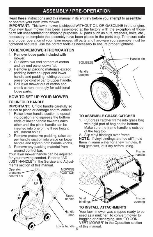
TO ASSEMBLE GRASS CATCH ER1. Put grass catcher frame into grass bag
with rigid part of bag on the bottom. Make sure the frame handle is outside of the bag top.
2. Slip vinyl bindings over frame.NOTE: If vinyl bindings are too stiff, hold them in warm water for a few minutes. If bag gets wet, let it dry before using.
TO INSTALL ATTACHMENTS Your lawn mower was shipped ready to be used as a mulcher. To convert mower to bagging or discharging, see “TO CON- VERT MOWER” in the Operation section of this manual.
Frame handle
Frame opening
Vinyl bindings
MOWING POSITION
Lower handle
LIFT UP
Operator presence control bar
Upper handle
LIFT UP
Handle knob
Read these instructions and this man u al in its entirety before you attempt to assemble or operate your new lawn mower. IMPORTANT: This lawn mower is shipped WITHOUT OIL OR GASOLINE in the engine.Your new lawn mower has been as sem bled at the factory with the ex cep tion of those parts left unassembled for shipping purposes. All parts such as nuts, washers, bolts, etc., necessary to com plete the as sem bly have been placed in the parts bag. To ensure safe and proper operation of your lawn mow er, all parts and hard ware you assemble must be tightened se cure ly. Use the correct tools as necessary to ensure proper tightness.
Handle bracket
Handle pinSQUEEZE
TO RE MOVE MOW ER FROM CAR TON1. Remove loose parts included with
mower.2. Cut down two end corners of carton
and lay end panel down fl at.3. Remove all packing materials ex cept
padding be tween upper and lower handle and padding holding operator presence control bar to upper handle.
4. Roll lawn mower out of carton and check carton thorougly for ad di tion al loose parts.
HOW TO SET UP YOUR MOW ER TO UNFOLD HANDLEIMPORTANT: Unfold handle carefully so as not to pinch or damage con trol cables. 1. Raise lower handle section to operat-
ing position and squeeze the bottom ends of lower handle towards each other until the pin in handle can be inserted into one of the three height adjustment holes.
2. Remove protective padding, raise up-per handle sec tion into place on lower handle and tighten both handle knobs.
3. Remove any packing material from around control bar.
Your lawn mower handle can be adjusted for your mowing comfort. Refer to “AD- JUST HANDLE” in the Service and Adjust-ments section of this manual.
43
MODEL NUMBER 128602-1102-E1BRIGGS & STRATTON 4-CYCLE ENGINE
524
842
847523
525
95
365
127
633
130
125
104
137
134
133
975
117
163
276
276
51A
202 209
188
287
957
190
972
121 CARBURETOR
104
134127
137 276977 CARBURETOR GASKET SET
633
633163
163137
51
613
883
300
613A
670
601
187
51
51
97
276
OVERHAUL KIT
276118
5151B
222
1059 1059
163
443
259
976
966
445
967
425
968
51A
51A 51B51B

42
MODEL NUMBER 128602-1102-E1BRIGGS & STRATTON 4-CYCLE ENGINE
7
1022
35
238
40
1034
1029
883
45
13
684
9
10
337
635
5
40
1022
914 383
8
868
306307
585619
33
34
1023
51A
1058 OPERATOR’S MANUAL
741
24
20
12
22
46
43
15
4
10227
1095 VALVE GASKET SET
26
32
27
27
562
505
616
615404
227
25 29
28
16
31
718
868
993
1026
36
830
192
51
11
886
51
11A
32A
163
2
993
914A
584
122
51A
51A883
51B
7
Single point height adjuster handle
IMPORTANT: This lawn mower is shipped WITHOUT OIL OR GASOLINE in the engine.
KNOW YOUR LAWN MOWERREAD THIS OWNER'S MANUAL AND ALL SAFETY RULES BEFORE OP ER AT ING YOUR LAWN MOWER. Compare the illustrations with your lawn mower to familiarize yourself with the location of various controls and adjustments. Save this manual for future reference.
These symbols may appear on your lawn mower or in literature supplied with the product. Learn and understand their meaning.
Operator presence control bar
Starter handle
Handle knob
MEETS CPSC SAFETY REQUIREMENTSSears rotary walk-behind power lawn mowers conform to the safety standards of the American National Standards Institute and the U.S. Consumer Product Safety Com- mis sion. The blade turns when the engine is running.
Operator presence control bar – must be held down to the handle to start the engine. Release to stop the engine.Starter handle – used for starting engine.Mulcher door – allows con ver sion to discharging or bagging operation.
Drive control lever – used to engage power-pro pelled forward mo tion of mower.Primer– pumps additional fuel from the carburetor to the cylinder for use when starting a cold engine.
Muffl er
Grass catcher
Drive control lever
OPERATION
Spark plug
Drive cover
Engine oil cap with dipstick
Air fi lter
Gasoline fi ller cap
HousingMulcher door
Primer

8
DRIVE CONTROL ADJUSTMENTOver time, the drive control system may become “loose”, resulting in decreased speed. There is a turnbuckle on the drive control housing to increase tension on the drive cable. Pro ceed as follows:1. Turn unit off and disconnect spark plug
wire from spark plug.2. Rotate turnbuckle on drive control to
increase drive speed.3. Operate mower to test drive speed.
Readjust as required.4. If condition fails to improve after the
above steps (forward speed remains the same), your drive belt is worn and should be re placed.
The operation of any lawn mower can result in foreign objects thrown into the eyes, which can result in severe eye dam-
age. Always wear safety glasses or eye shields while operating your lawn mower or performing any ad just ments or repairs. We recommend a standard safety glasses or wide vision safety mask worn over spectacles.
HOW TO USE YOUR LAWN MOWERENGINE SPEED Engine speed was set at the factory for optimum performance. It is not adjustable.
ENGINE ZONE CONTROL CAUTION: Federal regulations re quire
an engine control to be installed on this lawn mower in order to minimize the risk of blade contact injury. Do not un der any circumstances attempt to de feat the func tion of the operator con trol. The blade turns when the engine is running.• Your lawn mower is equipped with an
operator pres ence control bar which requires the operator to be positioned behind the lawn mower handle to start and operate the lawn mower.
DRIVE CONTROL • Self-propelling is controlled by hold-
ing the operator presence control bar down to the handle and pulling the drive control lever rearward to the handle. The farther toward the handle the lever is pulled, the faster the unit will travel.
• Forward motion will stop when either the operator presence control bar or drive control lever are released. To stop forward motion without stop ping engine, re lease the drive control lever only. Hold op er a tor presence control bar down against handle to con tin ue mowing without self-propelling.
NOTE: If after releasing the drive control the mower will not roll backwards, push the mower forward slightly to disengage drive wheels.
LEVER BACKWARD TO LOWER MOWER
LEVER FORWARD TO RAISE MOWER
Height adjuster lever
Adjustmentturnbuckle
TO ENGAGE
DRIVE CONTROL
Drive control lever
DRIVE CONTROL
DISENGAGED
Operator presence control bar
TO ADJUST CUTTING HEIGHT All four wheels are adjusted by a single lever.• Pull adjuster lever toward wheel. To
raise mower, move lever forward to desired position. To lower mow er, move the lever toward the rear.
41
HU
SQ
VA
RN
A R
OTA
RY
LA
WN
MO
WE
R -
- M
OD
EL
NU
MB
ER
91
7.3
74
45
6
NO
TE
: A
ll co
mpo
nent
dim
ensi
ons
give
n in
U.S
. inc
hes.
1 in
ch =
25.
4 m
m.
IMP
OR
TAN
T: U
se o
nly
Orig
inal
Equ
ipm
ent M
anuf
actu
rer
(O.E
.M.)
rep
lace
men
t par
ts.
Fai
lure
to d
o so
cou
ld b
e ha
zard
ous,
dam
age
your
law
n m
ower
and
voi
d yo
ur w
arra
nty.
KE
Y
PA
RT
NO
.
NO
.
D
ES
CR
IPT
ION
KE
Y
PA
RT
NO
.
NO
.
D
ES
CR
IPT
ION
1
40
7344
D
rive
Con
trol
Ass
embl
y2
4062
60X
460
C
over
, Top
3
40
6262
P
ulle
y 4
1900
39
Lev
er, D
rive
Con
trol
5
40
6261
X46
0
Cov
er, B
otto
m6
1816
98
Scr
ew7
4002
35X
479
M
ount
ing
Bra
cket
9
40
6258
C
able
, Driv
e11
4
0655
8
Spr
ing,
Ret
urn
13
404
839
G
ear
Cas
e A
ssem
bly
14
193
443
P
ulle
y, D
rive
15
883
48
W
ashe
r, F
lat
16
407
147
R
od, C
onne
ctin
g 17
4
0961
6
Spr
ing,
Ext
ensi
on
18
418
835X
004
S
prin
g, S
elec
tor
19
189
808X
418
K
nob,
Sel
ecto
r S
prin
g 20
1
2000
022
E-R
ing
7/8
21
4
0483
8
Bea
ring,
Sup
port
22
1
9103
9
Bea
ring,
Bal
l 23
1
6111
8X00
4
Ret
aine
r, D
rive
Ass
embl
y 24
1
7060
410
Scr
ew, T
appi
ng, H
ex H
ead
1/
4-20
x 3
/4
25
199
775X
418
C
over
Driv
e 26
7
5063
4
Scr
ew, T
hrea
ded,
Rol
led
#1
0-25
x .5
028
1
2000
058
E-R
ing
7/1
6 29
1
8940
3
Cov
er, D
ust,
Whe
el31
4
0484
5
Paw
l32
4
0574
6X46
0
Whe
el &
Tire
Ass
embl
y,
Rea
r 8
x 1
-3/4
33
4
0914
8
Nut
, Fla
ngel
ock
3/8
-16
34
851
226
W
ashe
r 35
4
0310
2X00
4
Sha
ft A
ssem
bly,
Rea
r36
4
0717
5X00
4
Sha
ft A
ssem
bly,
Fro
nt37
1
6146
3
Ret
aine
r, F
ront
Sha
ft38
1
6340
9
Scr
ew #
12 x
5/8
39
4
0705
9
Bol
t, S
houl
der,
S
emi-G
imle
tt P
oint
40
4
0127
3X46
0
Whe
el &
Tire
Ass
embl
y,
Fro
nt 8
x 1
-3/4
41
4
0483
5
Pin
ion
42
197
480
O
-Rin
g 44
4
0658
0
V-B
elt
KE
Y
PA
RT
NO
.
NO
.
D
ES
CR
IPT
ION
47
67
725
Was
her,
Fla
t49
1
6340
9
Scr
ew, H
i-Lo
Thr
ead
50
404
832X
004
B
elt K
eepe
r 6
0 41
2736
C
ase,
Upp
er 6
1 41
2757
S
haft,
Out
put,
Long
62
1835
08
Sea
l, O
utpu
t Sha
ft 6
3 18
3511
B
ushi
ng 6
4 18
3509
W
ashe
r 6
5 18
3514
S
eal,
Wor
m S
haft
66
1835
06
Bea
ring,
Bal
l 6
7 41
2742
G
ear,
28 T
eeth
68
4127
39
Fix
ed D
og C
lutc
h, L
H 6
9 41
2741
P
in, O
utpu
t Sha
ft 7
0 41
2740
M
ovab
le D
og C
lutc
h, L
H 7
1 41
2756
S
haft,
Out
put,
Sho
rt 7
2 18
3513
S
crew
, Cas
e 7
3 41
2747
C
ase,
Low
er 7
5 41
2746
P
in, W
orm
Sha
ft 7
6 41
2743
M
ovab
le D
og C
lutc
h, R
H 7
7 41
2744
F
ixed
Dog
Clu
tch,
RH
78
4107
31
Spr
ing,
Lea
f 7
9 41
2737
S
haft,
Wor
m

40
HU
SQ
VA
RN
A R
OTA
RY
LA
WN
MO
WE
R -
- M
OD
EL
NU
MB
ER
91
7.3
74
45
6
9
TO CONVERT MOWERYour lawn mower was shipped ready to be used as a mulcher. To convert to bagging or discharging:
REAR BAGGING • Open rear door and remove mulcher
plug. Store mulcher plug in a safe place.
• You can now install the grass catcher or optional clipping defl ector.
• To convert to mulching or discharging operation, install mulcher plug into rear discharge opening of mower.
SIDE DIS CHARG ING • Mulcher plug must be installed into rear
discharge open ing of mower.• Open mulcher door and install dis-
charge defl ector under door as shown.• Mower is now ready for discharging
operation.• To convert to mulching or bagging
operation, dis charge defl ector must be removed and mulcher door closed.
Open mulcher door
Discharge defl ector
SIMPLE STEPS TO REMEMBER WHEN CONVERTING YOUR LAWN MOWER
FOR MULCHING -1. Rear mulcher plug installed.2. Mulcher door closed.
FOR REAR BAGGING -1. Rear mulcher plug removed.2. Grass catcher installed.3. Mulcher door closed.
FOR SIDE DISCHARGING -1. Rear mulcher plug installed.2. Discharge defl ector installed.
CAUTION: Do not run your lawn mower with out mulcher plug or ap proved grass catch er in place. Never at tempt to op er ate the lawn mow er with the rear door re moved or propped open.
TO EMPTY GRASS CATCHER 1. Lift up on grass catcher using the
frame han dle.2. Remove grass catcher with clippings
from under lawn mower han dle.3. Empty clippings from bag.NOTE: Do not drag the bag when empty-ing; it will cause unnecessary wear.
Mulcher plug

10
BEFORE STARTING ENGINEADD OILYour lawnmower is shipped without oil in the engine. For type and grade of oil to use, see “EN GINE” in the Maintenance section of this manual.
CAUTION: DO NOT overfi ll engine with oil, or it will smoke heavily from the muffl er on startup.1. Be sure lawnmower is level. 2. Remove oil dipstick from oil fi ll spout.3. You receive a container of oil with the
unit. Slowly pour the entire container down the oil fi ll spout into the engine.
NOTE: Initial oil fi ll requires only 18 oz. due to residual oil in engine from the manufacturers 100% quality testing. When changing oil you may need 20 oz.4. Insert and tighten dipstick.IMPORTANT:• Check oil level before each use. Add oil
if needed. Fill to full line on dipstick.• Change the oil after every 25 hours of
operation or each season. You may need to change the oil more often under dusty, dirty conditions. See “TO CHANGE ENGINE OIL” in the Mainte-nance section of this manual.
ATTACH FUEL CAP CARTRIDGEYour mower is equipped with a special FRESH STARTTM fuel cap and continuous fuel preserver cartridge. See the infor-mation and instructions packed with the FRESH STARTTM cartridge.1. Snap cartridge into bottom of fuel cap.NOTE: Do not remove the silver foil seal on the side of cartridge that snaps into fuel cap.2. Grasp the white peel tab and pull to
remove the entire seal.3. Screw fuel cap onto fuel tank after fi ll-
ing tank with gasoline.Replace cartridge when empty (about once a season). Check preserver level visually.
DANGER: Cartridge fl uid is HARMFUL OR FATAL IF SWALLOWED. Avoid con-tact to eyes, skin, or clothing. Do not take internally. Do not inhale fl uid vapor. Keep out of reach of children. If swallowed, call a physician immediately.
ADD GASOLINE• Fill fuel tank to bottom of tank fi ller neck.
Do not overfi ll. Use fresh, clean, regular unleaded gasoline with a minimum of 87 octane. Do not mix oil with gasoline. Pur-chase fuel in quan ti ties that can be used within 30 days to assure fuel freshness. CAUTION: Wipe off any spilled oil or
fuel. Do not store, spill or use gasoline near an open fl ame.
CAUTION: Alcohol blended fuels (called gasohol or using ethanol or metha-nol) can attract moisture which leads to separation and for ma tion of acids during storage. Acidic gas can damage the fuel system of an engine while in storage. To avoid engine problems, the fuel system should be emptied before stor age of 30 days or longer. Empty the gas tank, start the engine and let it run until the fuel lines and carburetor are empty. Use fresh fuel next season. See Storage In struc tions for additional information. Never use engine or carburetor cleaner products in the fuel tank or permanent damage may occur.
Grass catcher
frame handle
Engine oil cap
Gasoline fi ller cap
Primer
39
HU
SQ
VA
RN
A R
OTA
RY
LA
WN
MO
WE
R -
- M
OD
EL
NU
MB
ER
91
7.3
74
45
6
KE
Y
PA
RT
NO
.
NO
.
D
ES
CR
IPT
ION
KE
Y
PA
RT
NO
.
NO
.
D
ES
CR
IPT
ION
1
19
9982
U
pper
Han
dle
Ass
embl
y (I
nclu
des
Foa
m G
rip)
2
19
3664
X49
8 H
andl
e, L
ower
3
40
5416
S
prin
g, R
ear
Doo
r, R
H4
1947
88
Rop
e G
uide
5
13
2004
N
ut, H
ex, w
ith L
ockw
ashe
r In
sert
1/4
-20
6
66
426
Wire
, Tie
7
19
1574
B
olt,
Han
dle
5/1
6-18
x 2
-5/8
8
18
5588
K
nob,
Han
dle
9
19
4580
X42
2 C
ontr
ol B
ar10
1888
21
Pin
, Han
dle
Adj
ustm
ent
11
75
1153
N
ut, H
ex12
5179
3
C
otte
r, H
airp
in13
4054
15
Spr
ing,
Rea
r D
oor,
LH14
7506
34
Scr
ew15
8507
33X
004
Bra
cket
, Ups
top
16
40
1815
X42
8 R
ear
Doo
r A
ssem
bly
17
18
4193
B
olt,
Rea
r D
oor
18
19
8170
P
lug,
Mul
cher
19
4104
53
Kit,
Hou
sing
20
19
3917
X42
2 H
andl
e B
rack
et A
sem
bly,
LH
21
19
3916
X42
2 H
andl
e B
rack
et A
ssem
bly,
RH
22
15
0078
S
crew
, Hex
Was
her
Hea
d23
1631
83
Bol
t, H
ex H
ead
5/1
6-18
x 5
/824
7380
0500
Nut
, Hex
, with
Loc
kwas
her
Inse
rt 5
/16-
1825
1613
33
Baf
fl e, S
ide
26
16
3409
S
crew
, Hi-L
o T
hrea
d #
12 x
5/8
27
40
8442
S
kirt
, Rea
r28
8865
2
S
crew
, Hin
ge 1
/4-2
0 x
1.25
29
19
1221
C
able
, Ope
rato
r P
rese
nce
30
18
9179
B
lade
Ada
pter
/ P
ulle
y31
4067
12
Bla
de, 2
1"32
8510
74
Was
her
33
85
0263
W
ashe
r, Lo
ck34
8510
84
Bol
t, H
ex H
ead
35
40
5843
D
ebris
Shi
eld
36
19
2325
B
olt
37
15
0406
B
olt,
Eng
ine
38
- -
-
E
ngin
e, B
riggs
& S
trat
ton,
Mod
el N
umbe
r
12
8602
-110
2-E
1 (S
ee B
reak
dow
n)
39
40
9726
G
rass
bag
40
41
1951
F
ram
e, G
rass
bag
41
40
4763
D
ange
r D
ecal
42
54
583
Scr
ew45
1830
58X
418
Mul
cher
Doo
r A
ssem
bly
46
16
9699
X41
8 D
isch
arge
Gua
rd47
8834
9
N
ut, H
ex48
1888
39X
004
Mou
ntin
g B
rack
et, D
ebris
Shi
eld
58
18
2003
C
lip, P
acka
ging
59
18
2748
G
rip, F
oam
96
19
7991
C
lip, C
able
- -
4
0476
4
War
ning
Dec
al (
not s
how
n)-
-
419
903
O
wne
r’s M
anua
l, E
nglis
h / S
pani
shA
vaila
ble
acce
ssor
ies
not i
nclu
ded
with
law
n m
ower
:-
-
71
336
23
G
as C
an (
2.5
Gal
lon
Con
tain
er)
- -
7
1 3
3500
Fue
l Sta
biliz
er-
-
71
330
00
S
AE
30W
Oil
(20
Oun
ce B
ottle
)
NO
TE
: A
ll co
mpo
nent
dim
ensi
ons
give
n in
U.S
. inc
hes.
1 in
ch =
25.
4 m
m.
IMP
OR
TAN
T: U
se o
nly
Orig
inal
Equ
ipm
ent M
anuf
actu
rer
(O.E
.M.)
rep
lace
men
t par
ts.
Fai
lure
to d
o so
cou
ld b
e ha
zard
ous,
dam
age
your
law
n m
ower
and
voi
d yo
ur w
arra
nty.

38
HU
SQ
VA
RN
A R
OTA
RY
LA
WN
MO
WE
R -
- M
OD
EL
NU
MB
ER
91
7.3
74
45
6
REPAIR PARTS
11
MULCHING MOWING TIPSIMPORTANT: For best performance, keep mower housing free of built-up grass and trash. See “CLEANING” in the Maintenance section of this manual.• The special mulching blade will recut
the grass clip pings many times and reduce them in size so that as they fall onto the lawn they will disperse into the grass and not be noticed. Also, the mulched grass will bio de grade quick ly to provide nu tri ents for the lawn. Always mulch with your highest engine (blade) speed as this will provide the best recut-ting action of the blades.
• Avoid cutting your lawn when it is wet. Wet grass tends to form clumps and in ter feres with the mulch ing action. The best time to mow your lawn is the early afternoon. At this time the grass has dried, yet the newly cut area will not be exposed to direct sunlight.
• For best results, adjust the lawn mower cutting height so that the lawn mower cuts off only the top one-third of the grass blades. If the lawn is over grown it will be nec es sary to raise the height of cut to reduce pushing effort and to keep from over load ing the engine and leaving clumps of mulched grass. For ex tremely heavy grass, reduce your width of cut by overlapping previously cut path and mow slowly.
• Certain types of grass and grass con di tions may re quire that an area be mulched a second time to com pletely hide the clip pings. When doing a sec- ond cut, mow across (perpendicular) to the fi rst cut path.
• Change your cutting pattern from week to week. Mow north to south one week then change to east to west the next week. This will help prevent matting and graining of the lawn.
TO STOP ENGINE• To stop engine, release operator pres-
ence con trol bar.
TO START ENGINE NOTE: Due to protective coatings on the engine, a small amount of smoke may be present during the initial use of the product and should be considered normal.1. To start a cold engine, push primer
three (3) times before trying to start. Use a fi rm push. This step is not usually necessary when starting an engine which has already run for a few minutes.
2. Hold operator presence control bar down to the han dle and pull starter handle quickly. Do not allow starter rope to snap back.
NOTE: In cooler weather it may be necessary to repeat priming steps. In warmer weather over priming may cause fl ooding and engine will not start. If you do fl ood engine, wait a few minutes before attempting to start and do not repeat priming steps.
MOWING TIPS CAUTION: Do not use de-thatcher
blade attachments on your mower. Such attachments are hazardous, will damage your mower and could void your warranty.• Under certain conditions, such as very
tall grass, it may be nec es sary to raise the height of cut to reduce pushing effort and to keep from overloading the engine and leaving clumps of grass clippings. It may also be necessary to re duce ground speed and/or run the lawn mower over the area a sec ond time.
• For extremely heavy cutting, re duce the width of cut by over lap ping previously cut path and mow slowly.
• For better grass bagging and most cut-ting conditions, the engine speed should be set in the FAST po si tion.
• Pores in cloth grass catchers can become fi lled with dirt and dust with use and catchers will collect less grass. To prevent this, reg u lar ly hose catcher off with water and let dry before using.
• Keep top of engine around starter clear and clean of grass clippings and chaff. This will help engine air fl ow and extend engine life.
MAX 1/3

12
Check for Loose FastenersClean / Inspect Grass Catcher *Check TiresCheck Drive Wheels ***Clean Lawn Mower ****Clean under Drive Cover ***Check Drive Belt / Pulleys ***Check / Sharpen / Replace BladeLubricationClean and Recharge Battery **
Check Engine Oil levelChange Engine OilClean Air FilterInspect MufflerReplace Spark PlugReplace Air Filter Paper CartridgeEmpty fuel system or add Stabilizer
BEFOREEACHUSE
AFTEREACHUSE
EVERY10
HOURS
EVERY25 HOURS
OR SEASON
EVERY100
HOURSBEFORE
STORAGE
1 - Change more often if operating under a heavy load or in high outdoor temperatures.2 - Service more often if operating in dirty or dusty conditions.3 - Replace blades more often when mowing in sandy soil.4 - Charge 48 hours at end of season.5 - And after each 5 hours of use.
(if so equipped)Electric-Start mowersPower-Propelled mowersUse a scraperto clean under deck
***
*******
MAINTENANCE
GENERAL REC OM MEN DA TIONSThe warranty on this lawn mower does not cover items that have been sub ject ed to operator abuse or negligence. To receive full value from the warranty, operator must maintain unit as in struct ed in this manual.Some adjustments will need to be made periodically to properly maintain your unit.At least once a season, check to see if you should make any of the adjustments described in the Service and Ad just ments section of this manual.• At least once a year, replace the spark
plug, clean or replace air fi lter element and check blade for wear. A new spark plug and clean/new air fi lter element assure proper air-fuel mix ture and help your engine run bet ter and last longer.
• Follow the maintenance schedule in this manual.
BEFORE EACH USE• Check engine oil level.• Check for loose fasteners.
LUBRICATIONKeep unit well lubricated(See “LU BRI CA TION CHART”).
LUBRICATION CHART
➀ Spray lubricant➁ See "ENGINE" in Maintenance section.
IMPORTANT: Do not oil or grease plastic wheel bearings. Viscous lu bri cants willattract dust and dirt that will short en the life of the self-lu bri cat ing bearings. If you feel they must be lu bri cated, use only a dry, pow dered graphite type lubricant spar ingly.
➀ Wheel adjuster (on each wheel)
➁ Engine oil
➀ Rear door hinge
➀ Handle bracket mounting pins
➀ Mulcher door hinge
pin
37
No arranca 7. Cuchilla suelta o adaptador 7. Apriete el perno de la cuchilla(continuado) de la cuchilla quebrado. cambie el adaptador de la cuchilla. 8. Barra de control en la 8. Presione la barra de control posición suelta. hacia el mango. 9. Barra de control defectuosa. 9. Cambie la barra de control. 10. Válvula del combustible (si equ- 10. Gire a la válvula del combustible ipada) está en la posición OFF. a la posición ON.
Falta de 1. Cuchilla desgastada, doblada 1. Eleve la altura de corte. fuerza o suelta. 2. Altura de las ruedas dispareja. 2. Eleve la altura de corte. 3. Velocidad del motor lenta. 3. Limpie/cambie el fi ltro de aire. 4. Acumulación de césped, hojas o 4. Limpie la parte inferior de la basura debajo de la segadora. caja de la segadora. 5. Demasiado aceite en motor. 5. Revise el nivel del aceite. 6. Velocidad de recorrido 6. Corte a una velocidad de demasiado rápida. recorrido más lenta.
Mal corte- 1. Cuchilla desgastada, doblada 1. Cambie la cuchilla. Apriete el pernodisparejo o suelta. de la cuchilla. 2. Altura de las ruedas dispareja. 2. Ajuste todas las ruedas a la misma altura. 3. Acumulación de césped, hojas o 3. Limpie la parte inferior de la basura debajo de la segadora. caja de la segadora.
Vibración 1. Cuchilla desgastada, doblada 1. Cambie la cuchilla. Apriete elexcesiva o suelta. perno de la cuchilla. 2. Cigueñal del motor doblado. 2. Póngase en contacto con su centro de servicio Husqvarna o con un otro centro de servicio cualifi cado.
Cordón 1. El freno del volante del motor 1. Presione la barra de controlarrancador está aplicado cuando se hacia el mango superior antes difícil de tirar suelta la barra de control. de tirar el cordón arrancador. 2. Cigueñal del motor doblado. 2. Póngase en contacto con su centro de servicio Husqvarna o con un otro centro de servicio cualifi cado. 3. Adaptador de la cuchilla quebrado. 3. Cambie el adaptador de la cuchilla. 4. La cuchilla se arrastra en 4. Mueva la segadora a un lugar el césped. en donde el césped ha sido cortado o a una superfi cie fi rme para hacer arrancar el motor.
Recogedor de 1. Altura de corte demasiado baja. 1. Eleve la altura de corte.césped no se 2. Levantamiento de la cuchilla 2. Cambie las cuchillas.llena (si viene desgastado.equipado) 3. Recogedor sin ventilación de aire. 3. Limpie el recogedor de césped.
Difícil de 1. El césped está demasiado alto o la 1. Eleve la altura de corte.empujar altura de la rueda demasiado baja. 2. Parte trasera de la 2. Eleve la parte trasera de la caja de caja/cuchilla de la segadora la segadora (1) un lugar más alto. arrastrándose en el césped. 3. Recogedor de césped 3. Vacíe el recogedor de césped. demasiado lleno. 4. Posición de la altura del mango 4. Ajuste la altura del mango de no adecuada para usted. modo que le acomode.
Pérdida de 1. Desgaste de la correa. 1. Re vise/cambie correa de impulsión.impulsión 2. La correa está fuera de la polea. 2. Revise/vuelva a instalar lao retardase 3. Cable de la impulsión usado o roto. 3. Cambie el cable de la impulsión.de la 4. El sistema de control del 4. Ajuste el control del mecanismovelocidad mecanismo impulsor “suelto”. impulsor.
PROBLEMA CAUSA CORRECCIÓN
SOLUCIÓN DE PROBLEMAS - Vea la sección apropiada en el manual amenos que esté dirigido a un centro de servico Husqvarna.

36
ACEITE DEL MOTORDrene el aceite (con el motor caliente) y cám-bielo con aceite de motor limpio. (Vea “MO-TOR” en la sección de Mantenimento de este manual.)
CILINDRO1. Remueva la bujía.2. Vacíe una onza (29 ml) de aceite a través
del agujero de la bujía en el cilindro.3. Tire la manilla de arranque lentamente unas
cuantas veces para distribuir el aceite.4. Vuelva a montar la nueva bujía.
OTROS• No guarde la gasolina de una temporada a la
otra.
No arranca 1. Filtro de aire sucio. 1. Limpie/cambie el fi ltro de aire. 2. Sin combustible. 2. Llene el estanque de combustible. 3. Combustible rancio. 3. Vaciar el estanque y vuelva a llenar- lo con combustible limpio y nuevo. 4. Agua en el combustible. 4. Vaciar el estanque y vuelva a llenar- lo con combustible limpio y nuevo. 5. Alambre de la bujía desconectado. 5. Conecte el alambre a la bujía. 6. Bujía mala. 6. Cambie la bujía.
PROBLEMA CAUSA CORRECCIÓN
SOLUCIÓN DE PROBLEMAS - Vea la sección apropiada en el manual amenos que esté dirigido a un centro de servico Husqvarna.
• Cambie el envase de la gasolina si se emp-ieza a oxidar. La oxidación y/o la mugre en su gasolina producirán problemas.
• Si es posible, guarde su unidad en un recinto cerrado y cúbrala para protegerla contra el polvo y la mugre.
• Cubra su unidad con un forro protector adecuado que no retenga la humedad. No use plástico. El plástico no puede respirar, lo que permite la formación de condensación, lo que producirá la oxidación de su unidad.
IMPORTANTE: Nunca cubra la segadora mientras el motor y las areas de escape todavia estan calientes.
PRECAUCIÓN: Nunca almacene la segadora con gasolina en el estanque dentro de un edifi cio en donde los gases pueden alcanzar una llama expuesta o una chispa. Permita que se enfríe el motor antes de almacenarla en algún recinto cerrado.
13
LAWN MOWERAlways observe safety rules when per- form ing any main te nance.
TIRES• Keep tires free of gasoline, oil, or insect
control chemi cals which can harm rubber.• Avoid stumps, stones, deep ruts, sharp
objects and other hazards that may cause tire damage.
DRIVE WHEELSCheck rear drive wheels each time be fore you mow to be sure they move freely.The wheels not turning freely means trash, grass cuttings, etc. are in the drive wheel area and must be cleaned to free drive wheels.If necessary to clean the drive wheels, be sure to clean both rear wheels.
BLADE CAREFor best results, blade must be kept sharp. Re place a bent or dam aged blade.
CAUTION: Use only a replacement blade approved by the manufacturer of your mower. Using a blade not approved by the manufacturer of your mower is haz-ardous, could damage your mower and void your warranty.
TO REMOVE BLADE1. Disconnect spark plug wire from spark
plug and place wire where it cannot come in contact with plug.
2. Turn lawn mower on its side. Make sure air fi lter and carburetor are up.
3. Use a wood block between blade and mower hous ing to prevent blade from turning when re mov ing blade bolt.
NOTE: Protect your hands with gloves and/or wrap blade with heavy cloth.4. Remove blade bolt by turning counter-
clockwise. 5. Remove blade & attaching hard ware
(bolt, lock wash er & hardened wash er).
TO REPLACE BLADE 1. Position blade on the blade adapter
aligning the two (2) holes in the blade with the raised lugs on the adapter.
2. Be sure the trailing edge of blade (oppo-site sharp edge) is up toward engine.
3. Install the blade bolt with the lock washer and hardened washer into blade adapter and crankshaft.
4. Use block of wood between blade and lawn mower housing and tighten the blade bolt, turning clockwise.
• The recommended tightening torque is 35-40 ft. lbs.
IMPORTANT: Blade bolt is heat treated. If bolt needs replacing, replace only with approved bolt shown in the Repair Parts section of this manual.
Blade bolt
Crankshaft keyway
Hardened washer
Lockwasher
Blade adapter Key
Blade
Trailing edge Crankshaft
TO SHARPEN BLADENOTE: We do not recommend sharp- en ing the blade - but if you do, be sure the blade is balanced. An un bal anced blade will cause eventual damage to mower or engine. • The blade can be sharp ened with a fi le
or on a grinding wheel. Do not attempt to sharpen while on the mower.
• To check blade balance, drive a nail into a beam or wall. Leave about one inch of the straight nail ex posed. Place center hole of blade over the head of the nail. If blade is balanced, it should remain in a horizontal position. If either end of the blade moves downward, sharpen the heavy end until the blade is balanced.
GRASS CATCHER• The grass catcher may be hosed with
water, but must be dry when used.• Check your grass catcher often for dam-
age or de te ri o ra tion. Through normal use it will wear. If catcher needs replac-ing, replace only with ap proved replace-ment catcher shown in the Repair Parts section of this manual. Give the lawn mower model number when ordering.
GEAR CASE • To keep your drive system working
properly, the gear case and area around the drive should be kept clean and free of trash build-up. Clean under the drive cover twice a season.
• The gear case is fi lled with lubricant to the proper level at the factory. The only time the lubricant needs attention is if service has been performed on the gear case.
• If lubricant is required, use only Texaco Starplex Pre mi um 1 Grease, Part No. 750369. Do not substitute.

38
HU
SQ
VA
RN
A R
OTA
RY
LA
WN
MO
WE
R -
- M
OD
EL
NU
MB
ER
91
7.3
74
45
6REPAIR PARTS
11
MULCHING MOWING TIPSIMPORTANT: For best performance, keep mower housing free of built-up grass and trash. See “CLEANING” in the Maintenance section of this manual.• The special mulching blade will recut
the grass clip pings many times and reduce them in size so that as they fall onto the lawn they will disperse into the grass and not be noticed. Also, the mulched grass will bio de grade quick ly to provide nu tri ents for the lawn. Always mulch with your highest engine (blade) speed as this will provide the best recut-ting action of the blades.
• Avoid cutting your lawn when it is wet. Wet grass tends to form clumps and in ter feres with the mulch ing action. The best time to mow your lawn is the early afternoon. At this time the grass has dried, yet the newly cut area will not be exposed to direct sunlight.
• For best results, adjust the lawn mower cutting height so that the lawn mower cuts off only the top one-third of the grass blades. If the lawn is over grown it will be nec es sary to raise the height of cut to reduce pushing effort and to keep from over load ing the engine and leaving clumps of mulched grass. For ex tremely heavy grass, reduce your width of cut by overlapping previously cut path and mow slowly.
• Certain types of grass and grass con di tions may re quire that an area be mulched a second time to com pletely hide the clip pings. When doing a sec- ond cut, mow across (perpendicular) to the fi rst cut path.
• Change your cutting pattern from week to week. Mow north to south one week then change to east to west the next week. This will help prevent matting and graining of the lawn.
TO STOP ENGINE• To stop engine, release operator pres-
ence con trol bar.
TO START ENGINE NOTE: Due to protective coatings on the engine, a small amount of smoke may be present during the initial use of the product and should be considered normal.1. To start a cold engine, push primer
three (3) times before trying to start. Use a fi rm push. This step is not usually necessary when starting an engine which has already run for a few minutes.
2. Hold operator presence control bar down to the han dle and pull starter handle quickly. Do not allow starter rope to snap back.
NOTE: In cooler weather it may be necessary to repeat priming steps. In warmer weather over priming may cause fl ooding and engine will not start. If you do fl ood engine, wait a few minutes before attempting to start and do not repeat priming steps.
MOWING TIPS CAUTION: Do not use de-thatcher
blade attachments on your mower. Such attachments are hazardous, will damage your mower and could void your warranty.• Under certain conditions, such as very
tall grass, it may be nec es sary to raise the height of cut to reduce pushing effort and to keep from overloading the engine and leaving clumps of grass clippings. It may also be necessary to re duce ground speed and/or run the lawn mower over the area a sec ond time.
• For extremely heavy cutting, re duce the width of cut by over lap ping previously cut path and mow slowly.
• For better grass bagging and most cut-ting conditions, the engine speed should be set in the FAST po si tion.
• Pores in cloth grass catchers can become fi lled with dirt and dust with use and catchers will collect less grass. To prevent this, reg u lar ly hose catcher off with water and let dry before using.
• Keep top of engine around starter clear and clean of grass clippings and chaff. This will help engine air fl ow and extend engine life.
MAX 1/3

10
BEFORE STARTING ENGINEADD OILYour lawnmower is shipped without oil in the engine. For type and grade of oil to use, see “EN GINE” in the Maintenance section of this manual.
CAUTION: DO NOT overfi ll engine with oil, or it will smoke heavily from the muffl er on startup.1. Be sure lawnmower is level. 2. Remove oil dipstick from oil fi ll spout.3. You receive a container of oil with the
unit. Slowly pour the entire container down the oil fi ll spout into the engine.
NOTE: Initial oil fi ll requires only 18 oz. due to residual oil in engine from the manufacturers 100% quality testing. When changing oil you may need 20 oz.4. Insert and tighten dipstick.IMPORTANT:• Check oil level before each use. Add oil
if needed. Fill to full line on dipstick.• Change the oil after every 25 hours of
operation or each season. You may need to change the oil more often under dusty, dirty conditions. See “TO CHANGE ENGINE OIL” in the Mainte-nance section of this manual.
ATTACH FUEL CAP CARTRIDGEYour mower is equipped with a special FRESH STARTTM fuel cap and continuous fuel preserver cartridge. See the infor-mation and instructions packed with the FRESH STARTTM cartridge.1. Snap cartridge into bottom of fuel cap.NOTE: Do not remove the silver foil seal on the side of cartridge that snaps into fuel cap.2. Grasp the white peel tab and pull to
remove the entire seal.3. Screw fuel cap onto fuel tank after fi ll-
ing tank with gasoline.Replace cartridge when empty (about once a season). Check preserver level visually.
DANGER: Cartridge fl uid is HARMFUL OR FATAL IF SWALLOWED. Avoid con-tact to eyes, skin, or clothing. Do not take internally. Do not inhale fl uid vapor. Keep out of reach of children. If swallowed, call a physician immediately.
ADD GASOLINE• Fill fuel tank to bottom of tank fi ller neck.
Do not overfi ll. Use fresh, clean, regular unleaded gasoline with a minimum of 87 octane. Do not mix oil with gasoline. Pur-chase fuel in quan ti ties that can be used within 30 days to assure fuel freshness. CAUTION: Wipe off any spilled oil or
fuel. Do not store, spill or use gasoline near an open fl ame.
CAUTION: Alcohol blended fuels (called gasohol or using ethanol or metha-nol) can attract moisture which leads to separation and for ma tion of acids during storage. Acidic gas can damage the fuel system of an engine while in storage. To avoid engine problems, the fuel system should be emptied before stor age of 30 days or longer. Empty the gas tank, start the engine and let it run until the fuel lines and carburetor are empty. Use fresh fuel next season. See Storage In struc tions for additional information. Never use engine or carburetor cleaner products in the fuel tank or permanent damage may occur.
Grass catcher
frame handle
Engine oil cap
Gasoline fi ller cap
Primer
39
HU
SQ
VA
RN
A R
OTA
RY
LA
WN
MO
WE
R -
- M
OD
EL
NU
MB
ER
91
7.3
74
45
6
KE
Y
PA
RT
NO
.
NO
.
D
ES
CR
IPT
ION
KE
Y
PA
RT
NO
.
NO
.
D
ES
CR
IPT
ION
1
19
9982
U
pper
Han
dle
Ass
embl
y (I
nclu
des
Foa
m G
rip)
2
19
3664
X49
8 H
andl
e, L
ower
3
40
5416
S
prin
g, R
ear
Doo
r, R
H4
1947
88
Rop
e G
uide
5
13
2004
N
ut, H
ex, w
ith L
ockw
ashe
r In
sert
1/4
-20
6
66
426
Wire
, Tie
7
19
1574
B
olt,
Han
dle
5/1
6-18
x 2
-5/8
8
18
5588
K
nob,
Han
dle
9
19
4580
X42
2 C
ontr
ol B
ar10
1888
21
Pin
, Han
dle
Adj
ustm
ent
11
75
1153
N
ut, H
ex12
5179
3
C
otte
r, H
airp
in13
4054
15
Spr
ing,
Rea
r D
oor,
LH14
7506
34
Scr
ew15
8507
33X
004
Bra
cket
, Ups
top
16
40
1815
X42
8 R
ear
Doo
r A
ssem
bly
17
18
4193
B
olt,
Rea
r D
oor
18
19
8170
P
lug,
Mul
cher
19
4104
53
Kit,
Hou
sing
20
19
3917
X42
2 H
andl
e B
rack
et A
sem
bly,
LH
21
19
3916
X42
2 H
andl
e B
rack
et A
ssem
bly,
RH
22
15
0078
S
crew
, Hex
Was
her
Hea
d23
1631
83
Bol
t, H
ex H
ead
5/1
6-18
x 5
/824
7380
0500
Nut
, Hex
, with
Loc
kwas
her
Inse
rt 5
/16-
1825
1613
33
Baf
fl e, S
ide
26
16
3409
S
crew
, Hi-L
o T
hrea
d #
12 x
5/8
27
40
8442
S
kirt
, Rea
r28
8865
2
S
crew
, Hin
ge 1
/4-2
0 x
1.25
29
19
1221
C
able
, Ope
rato
r P
rese
nce
30
18
9179
B
lade
Ada
pter
/ P
ulle
y31
4067
12
Bla
de, 2
1"32
8510
74
Was
her
33
85
0263
W
ashe
r, Lo
ck34
8510
84
Bol
t, H
ex H
ead
35
40
5843
D
ebris
Shi
eld
36
19
2325
B
olt
37
15
0406
B
olt,
Eng
ine
38
- -
-
E
ngin
e, B
riggs
& S
trat
ton,
Mod
el N
umbe
r
12
8602
-110
2-E
1 (S
ee B
reak
dow
n)
39
40
9726
G
rass
bag
40
41
1951
F
ram
e, G
rass
bag
41
40
4763
D
ange
r D
ecal
42
54
583
Scr
ew45
1830
58X
418
Mul
cher
Doo
r A
ssem
bly
46
16
9699
X41
8 D
isch
arge
Gua
rd47
8834
9
N
ut, H
ex48
1888
39X
004
Mou
ntin
g B
rack
et, D
ebris
Shi
eld
58
18
2003
C
lip, P
acka
ging
59
18
2748
G
rip, F
oam
96
19
7991
C
lip, C
able
- -
4
0476
4
War
ning
Dec
al (
not s
how
n)-
-
419
903
O
wne
r’s M
anua
l, E
nglis
h / S
pani
shA
vaila
ble
acce
ssor
ies
not i
nclu
ded
with
law
n m
ower
:-
-
71
336
23
G
as C
an (
2.5
Gal
lon
Con
tain
er)
- -
7
1 3
3500
Fue
l Sta
biliz
er-
-
71
330
00
S
AE
30W
Oil
(20
Oun
ce B
ottle
)
NO
TE
: A
ll co
mpo
nent
dim
ensi
ons
give
n in
U.S
. inc
hes.
1 in
ch =
25.
4 m
m.
IMP
OR
TAN
T: U
se o
nly
Orig
inal
Equ
ipm
ent M
anuf
actu
rer
(O.E
.M.)
rep
lace
men
t par
ts.
Fai
lure
to d
o so
cou
ld b
e ha
zard
ous,
dam
age
your
law
n m
ower
and
voi
d yo
ur w
arra
nty.

40
HU
SQ
VA
RN
A R
OTA
RY
LA
WN
MO
WE
R -
- M
OD
EL
NU
MB
ER
91
7.3
74
45
6
9
TO CONVERT MOWERYour lawn mower was shipped ready to be used as a mulcher. To convert to bagging or discharging:
REAR BAGGING • Open rear door and remove mulcher
plug. Store mulcher plug in a safe place.
• You can now install the grass catcher or optional clipping defl ector.
• To convert to mulching or discharging operation, install mulcher plug into rear discharge opening of mower.
SIDE DIS CHARG ING • Mulcher plug must be installed into rear
discharge open ing of mower.• Open mulcher door and install dis-
charge defl ector under door as shown.• Mower is now ready for discharging
operation.• To convert to mulching or bagging
operation, dis charge defl ector must be removed and mulcher door closed.
Open mulcher door
Discharge defl ector
SIMPLE STEPS TO REMEMBER WHEN CONVERTING YOUR LAWN MOWER
FOR MULCHING -1. Rear mulcher plug installed.2. Mulcher door closed.
FOR REAR BAGGING -1. Rear mulcher plug removed.2. Grass catcher installed.3. Mulcher door closed.
FOR SIDE DISCHARGING -1. Rear mulcher plug installed.2. Discharge defl ector installed.
CAUTION: Do not run your lawn mower with out mulcher plug or ap proved grass catch er in place. Never at tempt to op er ate the lawn mow er with the rear door re moved or propped open.
TO EMPTY GRASS CATCHER 1. Lift up on grass catcher using the
frame han dle.2. Remove grass catcher with clippings
from under lawn mower han dle.3. Empty clippings from bag.NOTE: Do not drag the bag when empty-ing; it will cause unnecessary wear.
Mulcher plug

8
DRIVE CONTROL ADJUSTMENTOver time, the drive control system may become “loose”, resulting in decreased speed. There is a turnbuckle on the drive control housing to increase tension on the drive cable. Pro ceed as follows:1. Turn unit off and disconnect spark plug
wire from spark plug.2. Rotate turnbuckle on drive control to
increase drive speed.3. Operate mower to test drive speed.
Readjust as required.4. If condition fails to improve after the
above steps (forward speed remains the same), your drive belt is worn and should be re placed.
The operation of any lawn mower can result in foreign objects thrown into the eyes, which can result in severe eye dam-
age. Always wear safety glasses or eye shields while operating your lawn mower or performing any ad just ments or repairs. We recommend a standard safety glasses or wide vision safety mask worn over spectacles.
HOW TO USE YOUR LAWN MOWERENGINE SPEED Engine speed was set at the factory for optimum performance. It is not adjustable.
ENGINE ZONE CONTROL CAUTION: Federal regulations re quire
an engine control to be installed on this lawn mower in order to minimize the risk of blade contact injury. Do not un der any circumstances attempt to de feat the func tion of the operator con trol. The blade turns when the engine is running.• Your lawn mower is equipped with an
operator pres ence control bar which requires the operator to be positioned behind the lawn mower handle to start and operate the lawn mower.
DRIVE CONTROL • Self-propelling is controlled by hold-
ing the operator presence control bar down to the handle and pulling the drive control lever rearward to the handle. The farther toward the handle the lever is pulled, the faster the unit will travel.
• Forward motion will stop when either the operator presence control bar or drive control lever are released. To stop forward motion without stop ping engine, re lease the drive control lever only. Hold op er a tor presence control bar down against handle to con tin ue mowing without self-propelling.
NOTE: If after releasing the drive control the mower will not roll backwards, push the mower forward slightly to disengage drive wheels.
LEVER BACKWARD TO LOWER MOWER
LEVER FORWARD TO RAISE MOWER
Height adjuster lever
Adjustmentturnbuckle
TO ENGAGE
DRIVE CONTROL
Drive control lever
DRIVE CONTROL
DISENGAGED
Operator presence control bar
TO ADJUST CUTTING HEIGHT All four wheels are adjusted by a single lever.• Pull adjuster lever toward wheel. To
raise mower, move lever forward to desired position. To lower mow er, move the lever toward the rear.
41
HU
SQ
VA
RN
A R
OTA
RY
LA
WN
MO
WE
R -
- M
OD
EL
NU
MB
ER
91
7.3
74
45
6
NO
TE
: A
ll co
mpo
nent
dim
ensi
ons
give
n in
U.S
. inc
hes.
1 in
ch =
25.
4 m
m.
IMP
OR
TAN
T: U
se o
nly
Orig
inal
Equ
ipm
ent M
anuf
actu
rer
(O.E
.M.)
rep
lace
men
t par
ts.
Fai
lure
to d
o so
cou
ld b
e ha
zard
ous,
dam
age
your
law
n m
ower
and
voi
d yo
ur w
arra
nty.
KE
Y
PA
RT
NO
.
NO
.
D
ES
CR
IPT
ION
KE
Y
PA
RT
NO
.
NO
.
D
ES
CR
IPT
ION
1
40
7344
D
rive
Con
trol
Ass
embl
y2
4062
60X
460
C
over
, Top
3
40
6262
P
ulle
y 4
1900
39
Lev
er, D
rive
Con
trol
5
40
6261
X46
0
Cov
er, B
otto
m6
1816
98
Scr
ew7
4002
35X
479
M
ount
ing
Bra
cket
9
40
6258
C
able
, Driv
e11
4
0655
8
Spr
ing,
Ret
urn
13
404
839
G
ear
Cas
e A
ssem
bly
14
193
443
P
ulle
y, D
rive
15
883
48
W
ashe
r, F
lat
16
407
147
R
od, C
onne
ctin
g 17
4
0961
6
Spr
ing,
Ext
ensi
on
18
418
835X
004
S
prin
g, S
elec
tor
19
189
808X
418
K
nob,
Sel
ecto
r S
prin
g 20
1
2000
022
E-R
ing
7/8
21
4
0483
8
Bea
ring,
Sup
port
22
1
9103
9
Bea
ring,
Bal
l 23
1
6111
8X00
4
Ret
aine
r, D
rive
Ass
embl
y 24
1
7060
410
Scr
ew, T
appi
ng, H
ex H
ead
1/
4-20
x 3
/4
25
199
775X
418
C
over
Driv
e 26
7
5063
4
Scr
ew, T
hrea
ded,
Rol
led
#1
0-25
x .5
028
1
2000
058
E-R
ing
7/1
6 29
1
8940
3
Cov
er, D
ust,
Whe
el31
4
0484
5
Paw
l32
4
0574
6X46
0
Whe
el &
Tire
Ass
embl
y,
Rea
r 8
x 1
-3/4
33
4
0914
8
Nut
, Fla
ngel
ock
3/8
-16
34
851
226
W
ashe
r 35
4
0310
2X00
4
Sha
ft A
ssem
bly,
Rea
r36
4
0717
5X00
4
Sha
ft A
ssem
bly,
Fro
nt37
1
6146
3
Ret
aine
r, F
ront
Sha
ft38
1
6340
9
Scr
ew #
12 x
5/8
39
4
0705
9
Bol
t, S
houl
der,
S
emi-G
imle
tt P
oint
40
4
0127
3X46
0
Whe
el &
Tire
Ass
embl
y,
Fro
nt 8
x 1
-3/4
41
4
0483
5
Pin
ion
42
197
480
O
-Rin
g 44
4
0658
0
V-B
elt
KE
Y
PA
RT
NO
.
NO
.
D
ES
CR
IPT
ION
47
67
725
Was
her,
Fla
t49
1
6340
9
Scr
ew, H
i-Lo
Thr
ead
50
404
832X
004
B
elt K
eepe
r 6
0 41
2736
C
ase,
Upp
er 6
1 41
2757
S
haft,
Out
put,
Long
62
1835
08
Sea
l, O
utpu
t Sha
ft 6
3 18
3511
B
ushi
ng 6
4 18
3509
W
ashe
r 6
5 18
3514
S
eal,
Wor
m S
haft
66
1835
06
Bea
ring,
Bal
l 6
7 41
2742
G
ear,
28 T
eeth
68
4127
39
Fix
ed D
og C
lutc
h, L
H 6
9 41
2741
P
in, O
utpu
t Sha
ft 7
0 41
2740
M
ovab
le D
og C
lutc
h, L
H 7
1 41
2756
S
haft,
Out
put,
Sho
rt 7
2 18
3513
S
crew
, Cas
e 7
3 41
2747
C
ase,
Low
er 7
5 41
2746
P
in, W
orm
Sha
ft 7
6 41
2743
M
ovab
le D
og C
lutc
h, R
H 7
7 41
2744
F
ixed
Dog
Clu
tch,
RH
78
4107
31
Spr
ing,
Lea
f 7
9 41
2737
S
haft,
Wor
m

42
MODEL NUMBER 128602-1102-E1BRIGGS & STRATTON 4-CYCLE ENGINE
7
1022
35
238
40
1034
1029
883
45
13
684
9
10
337
635
5
40
1022
914 383
8
868
306307
585619
33
34
1023
51A
1058 OPERATOR’S MANUAL
741
24
20
12
22
46
43
15
4
10227
1095 VALVE GASKET SET
26
32
27
27
562
505
616
615404
227
25 29
28
16
31
718
868
993
1026
36
830
192
51
11
886
51
11A
32A
163
2
993
914A
584
122
51A
51A883
51B
7
Single point height adjuster handle
IMPORTANT: This lawn mower is shipped WITHOUT OIL OR GASOLINE in the engine.
KNOW YOUR LAWN MOWERREAD THIS OWNER'S MANUAL AND ALL SAFETY RULES BEFORE OP ER AT ING YOUR LAWN MOWER. Compare the illustrations with your lawn mower to familiarize yourself with the location of various controls and adjustments. Save this manual for future reference.
These symbols may appear on your lawn mower or in literature supplied with the product. Learn and understand their meaning.
Operator presence control bar
Starter handle
Handle knob
MEETS CPSC SAFETY REQUIREMENTSSears rotary walk-behind power lawn mowers conform to the safety standards of the American National Standards Institute and the U.S. Consumer Product Safety Com- mis sion. The blade turns when the engine is running.
Operator presence control bar – must be held down to the handle to start the engine. Release to stop the engine.Starter handle – used for starting engine.Mulcher door – allows con ver sion to discharging or bagging operation.
Drive control lever – used to engage power-pro pelled forward mo tion of mower.Primer– pumps additional fuel from the carburetor to the cylinder for use when starting a cold engine.
Muffl er
Grass catcher
Drive control lever
OPERATION
Spark plug
Drive cover
Engine oil cap with dipstick
Air fi lter
Gasoline fi ller cap
HousingMulcher door
Primer

6
ASSEMBLY / PRE-OPERATION
TO ASSEMBLE GRASS CATCH ER1. Put grass catcher frame into grass bag
with rigid part of bag on the bottom. Make sure the frame handle is outside of the bag top.
2. Slip vinyl bindings over frame.NOTE: If vinyl bindings are too stiff, hold them in warm water for a few minutes. If bag gets wet, let it dry before using.
TO INSTALL ATTACHMENTS Your lawn mower was shipped ready to be used as a mulcher. To convert mower to bagging or discharging, see “TO CON- VERT MOWER” in the Operation section of this manual.
Frame handle
Frame opening
Vinyl bindings
MOWING POSITION
Lower handle
LIFT UP
Operator presence control bar
Upper handle
LIFT UP
Handle knob
Read these instructions and this man u al in its entirety before you attempt to assemble or operate your new lawn mower. IMPORTANT: This lawn mower is shipped WITHOUT OIL OR GASOLINE in the engine.Your new lawn mower has been as sem bled at the factory with the ex cep tion of those parts left unassembled for shipping purposes. All parts such as nuts, washers, bolts, etc., necessary to com plete the as sem bly have been placed in the parts bag. To ensure safe and proper operation of your lawn mow er, all parts and hard ware you assemble must be tightened se cure ly. Use the correct tools as necessary to ensure proper tightness.
Handle bracket
Handle pinSQUEEZE
TO RE MOVE MOW ER FROM CAR TON1. Remove loose parts included with
mower.2. Cut down two end corners of carton
and lay end panel down fl at.3. Remove all packing materials ex cept
padding be tween upper and lower handle and padding holding operator presence control bar to upper handle.
4. Roll lawn mower out of carton and check carton thorougly for ad di tion al loose parts.
HOW TO SET UP YOUR MOW ER TO UNFOLD HANDLEIMPORTANT: Unfold handle carefully so as not to pinch or damage con trol cables. 1. Raise lower handle section to operat-
ing position and squeeze the bottom ends of lower handle towards each other until the pin in handle can be inserted into one of the three height adjustment holes.
2. Remove protective padding, raise up-per handle sec tion into place on lower handle and tighten both handle knobs.
3. Remove any packing material from around control bar.
Your lawn mower handle can be adjusted for your mowing comfort. Refer to “AD- JUST HANDLE” in the Service and Adjust-ments section of this manual.
43
MODEL NUMBER 128602-1102-E1BRIGGS & STRATTON 4-CYCLE ENGINE
524
842
847523
525
95
365
127
633
130
125
104
137
134
133
975
117
163
276
276
51A
202 209
188
287
957
190
972
121 CARBURETOR
104
134127
137 276977 CARBURETOR GASKET SET
633
633163
163137
51
613
883
300
613A
670
601
187
51
51
97
276
OVERHAUL KIT
276118
5151B
222
1059 1059
163
443
259
976
966
445
967
425
968
51A
51A 51B51B

44
MODEL NUMBER 128602-1102-E1BRIGGS & STRATTON 4-CYCLE ENGINE
1022
12
883
20
585
3
842524
163
7
358 ENGINE GASKET SET
993868
305
334
851
356
333
1036 EMISSIONS LABEL
455
332
23363
55
456
58
60459
689
597
608
592
65
1211
121048
922923
745
51
969921
1330 REPAIR MANUAL
1329 REPLACEMENT ENGINE
304
621
51A
51B
9
37
78
5
Serial Number:
Date of Purchase:
Gasoline Capacity / Type: 1.6 Quarts (Unleaded Regular)
Oil Type (API SG–SL): SAE 30 (above 32°F); SAE 5W-30 (below 32°F)
Oil Capacity: 20 Ounces
Spark Plug (Gap: .030") Champion RC12YC
Blade Bolt Torque: 35-40 ft. lbs.
• The model and serial numbers will be found on a decal on the rear of the lawn mower housing. Record both serial number and date of purchase in space provided above.
PRODUCT SPECIFICATIONS
ACCESSORIESThese accessories were available when this lawn mower was produced. They are not shipped with your mower. They are also available at most Husqvarna retailers and service centers. Some of these accessories may not apply to your lawn mower.

4
WARRANTYSECTION 1: LIMITED WARRANTYHusqvarna Forest & Garden Company (“Husqvarna”) warrants Husqvarna product to the original purchaser to be free from defects in material and workmanship from the date of purchase for the “Warranty Period” of the product as set forth below:
2 YEAR NON-COMMERCIAL WARRANTY: Auto-matic Mower, Riding lawn mowers, yard and garden tractors, walk behind mowers, tillers, chain saws, trimmers, brushcutters, clearing saws, snow blowers, handheld blowers, backpack blowers, hedge trimmers, electrical products and power-assist collection systems for non com mer cial, nonprofessional, noninstitutional or nonincome producing use, except as herein stated.
Emission control system components necessary to comply with CARB-TIER-II and EPA regulations.
Husqvarna Safety Apparel carries a 90-day warranty from the date of the customer’s original purchase for defects in material and workmanship. Normal wear, tear or abuse is not covered under warranty. Product must be returned to Charlotte with a warranty claim form. All care and maintenance instructions must be followed as stated by the manufacturer on the care label. The fi t of the protective apparel/boot is not covered under warranty.
SECTION 2: HUSQVARNA’S OBLIGATIONS UNDER THE WARRANTYHusqvarna will repair or replace defective components without charge for parts or labor if a component fails because of a defect in material or workmanship during the warranty period.
SECTION 3: ITEMS NOT COVERED BY THIS WAR-RANTYThe following items are not covered by this warranty:(1)Normal customer maintenance items which become
worn through normal regular use, including, but not limited to, belts, blades, blade adapters, bulbs, fi lters, guide bars, lubricants, rewind springs, saw chain, spark plugs, starter ropes and tines;
(2) Natural discoloration of material due to ultraviolet light;
(3) Lawn and garden attachments are covered by a third party which gives a warranty, all claims for warranty should be sent to the manufacturer; and
(4)Emission Control System components necessary to which are manufactured by third party engine manufacturer.
SECTION 4: EXCEPTIONS AND LIMITATIONSThis warranty shall be inapplicable to defects resulting from the following:(1) Accident, abuse, misuse, negligence and neglect,
including stale fuel, dirt, abrasives, moisture, rust, corrosion, or any adverse reaction due to incorrect storage or use habits;
(2) Failure to operate or maintain the unit in accor-dance with the Owner’s/Operator’s manual or instruction sheet furnished by Husqvarna;
(3) Alterations or modifi cations that change the intended use of the product or affects the product’s performance, operation, safety, or durability, or causes the product to fail to comply with any ap-plicable laws; or:
(4) Additional damage to parts or components due to continued use occurring after any of the above.
REPAIR OR REPLACEMENT AS PROVIDED UNDER THIS WARRANTY IS THE EXCLUSIVE REMEDY OF THE PUR CHAS ER. HUSQVARNA SHALL NOT BE LIABLE FOR ANY INCIDENTAL OR CONSEQUEN-TIAL DAMAGES FOR BREACH OF ANY EXPRESS OR IMPLIED WARRANTY ON THESE PRODUCTS EXCEPT TO THE EXTENT PROHIBITED BY AP-PLICABLE LAW. ANY IMPLIED WARRANTY OF MERCHANTABILITY OR FITNESS FOR A PARTICU-LAR PURPOSE ON THESE PRODUCTS IS LIMITED IN DURATION TO THE WARRANTY PERIOD AS DEFINED IN THE LIMITED WARRANTY STATE-MENT. HUSQVARNA RE SERVES THE RIGHT TO CHANGE OR IMPROVE THE DESIGN OF THE PRODUCT WITHOUT NO TICE, AND DOES NOT ASSUME OBLIGATION TO UPDATE PREVIOUSLY MANUFACTURED PROD UCTS.
Some states do not allow the exclusion of incidental or consequential damages, or limitations on how long an implied warranty lasts, so the above limitations or exclusions may not apply to you. This warranty gives you specifi c legal rights, and you may also have other rights which vary from state to state.
SECTION 5: CUSTOMER RESPONSIBILITIESThe product must exhibit reasonable care, mainte-nance, operation, storage and general upkeep as written in the maintenance section of the Owner’s/Operator’s manual. Should an operational problem or failure occur, the product should not be used, but delivered as is to an authorized Husqvarna dealer for evaluation. Proof of purchase, as explained in section 6, rests solely with the customer.
SECTION 6: PROCEDURE TO OBTAIN WARRANTY CONSIDERATIONIt is the Owner’s and Dealer’s responsibility to make certain that the Warranty Registration Card is properly fi lled out and mailed to Husqvarna Forest & Garden Company. This card should be mailed within ten (10) days from the date of purchase in order to confi rm the warranty and to facilitate post-sale service.
Proof of purchase must be presented to the authorized Husqvarna dealer in order to obtain warranty service. This proof must include date purchased, model num-ber, serial number, and complete name and address of the selling dealer.
To obtain the benefi t of this warranty, the product believed to be defective must be delivered to an authorized Husqvarna dealer in a timely manner, no later than thirty (30) days from date of the operational problem or failure. The product must be delivered at the owner’s expense. Pick-up and delivery charges are not covered by this warranty. An authorized Husqvarna dealer can be normally located through the “Yellow Pages” of the local telephone directory or by calling 1-800-HUSKY62 for a dealer in your area.
HUSQVARNA 7349 Statesville RoadCharlotte, NC 28269531 83 81-23 2002
45
MODEL NUMBER 128602-1102-E1BRIGGS & STRATTON 4-CYCLE ENGINE
KEY PARTNO. NO. DESCRIPTION
1 692670 Cylinder Assembly2 399269 Kit-Bushing/Seal3 299819s • Seal-Oil (Magneto Side)4 493279 Sump-Engine5 792381 Head-Cylinder7 697230 •+ Gasket-Cylinder Head8 495786 Breather Assembly9 699833 • Gasket-Breather10 691125 Screw (Breather Assembly)11 691781 Tube-Breather11A 692937 Tube-Breather12 692232 • Gasket-Crankcase13 691137 Screw (Cylinder Head)15 691680 Plug-Oil Drain16 691456 Crankshaft 20 399781s • Seal-Oil (PTO Side)22 691092 Screw (Engine Sump)23 697610 Flywheel24 222698s Key-Flywheel25 795429 Piston Assembly (Standard Size) 795430 Piston Assembly (.020" Oversize)26 795431 Ring Set (Standard) 795432 Ring Set (.020" Oversize)27 691866 Lock-Piston Pin28 499423 Pin-Piston29 499424 Rod-Connecting32 691664 Screw (Connecting Rod)32A 695759 Screw (Connecting Rod)33 499642 Valve-Exhaust34 499641 Valve-Intake35 691304 Spring-Valve (Intake)36 691304 Spring-Valve (Exhaust)37 793756 Guard-Flywheel40 692194 Retainer-Valve43 691997 Slinger-Governor/Oil45 690977 Tappet-Valve46 694039 Camshaft48 692748 Short Block 51 692668 • ؇+ Gasket-Intake51A 692555 •Ø‡+ Gasket-Intake51B 697735 •Ø‡+ Gasket-Intake55 691421 Housing-Rewind Starter58 697316 Rope-Starter (Cut to Required Length)60 281434s Grip-Starter Rope
KEY PARTNO. NO. DESCRIPTION
65 690837 Screw (Rewind Starter)78 691108 Screw (Flywheel Guard)95 691636 Screw (Throttle Valve)97 790121 Shaft-Throttle104 691242 Ø Pin-Float Hinge117 498981 Jet-Main (Standard)118 498978 Jet-Main (High Altitude)121 792383 Kit-Carburetor Overhaul122 792382 Spacer-Carburetor125 790120 Carburetor127 694468 Ø Plug-Welch130 696564 Valve-Throttle133 398187 Float-Carburetor134 398188 Ø Valve-Needle/Seat 137 693981 ؇ Gasket-Float Bowl163 691894 •Ø‡+ Gasket-Air Cleaner187 791766 Line-Fuel (Cut to Required Length)188 691147 Screw (Control Bracket)190 690940 Screw (Fuel Tank)192 694543 Ball-Rocker Arm202 691303 Link-Mechanical Governor209 691851 Spring-Governor222 697614 Bracket-Control227 691467 Control Lever-Governor238 691300 Cap-Valve259 691189 Bracket-Casing Clamp276 271716 ؇ Washer-Sealing287 690940 Screw (Dipstick Tube)300 697590 Muffl er304 695976 Housing-Blower305 691108 Screw (Blower Housing)306 691232 Shield-Cylinder307 690345 Screw (Cylinder Shield)332 690662 Nut (Flywheel)333 802574 Armature-Magneto334 691061 Screw (Armature Magneto)337 692051 Plug-Spark356 692390 Wire-Stop358 795442 Gasket Set-Engine363 19069 Puller-Flywheel365 691129 Screw (Carburetor)383 19374s Wrench-Spark Plug404 690272 Washer (Governor Crank)425 690244 Screw (Air Cleaner Cover)443 690255 Screw (Air Cleaner Primer Base)

46
MODEL NUMBER 128602-1102-E1BRIGGS & STRATTON 4-CYCLE ENGINE
KEY PARTNO. NO. DESCRIPTION
445 697029 Filter, Air Cleaner Cartridge455 791960 Cup-Flywheel456 692299 Plate-Pawl Friction459 281505s Pawl-Ratchet505 691251 Nut (Governor Control Lever)523 499621 Dipstick524 692296 • Seal-Dipstick Tube525 495265 Tube-Dipstick562 92613 Bolt (Governor Control Lever)584 697734 Cover-Breather Passage585 691879 • Gasket-Breather Passage592 690800 Nut (Rewind Starter)597 691696 Screw (Pawl Friction Plate)601 791850 Clamp-Hose608 497680 Starter-Rewind613 691108 Screw (Muffl er)613A 691140 Screw (Muffl er)615 690340 Retainer-Governor Shaft616 698801 Crank-Governor619 691108 Screw (Cylinder Head Plate)621 692310 Switch-Stop633 691321 ؇ Seal-Throttle Shaft635 66538s Boot-Spark Plug670 692294 Spacer-Fuel Tank684 690345 Screw (Breather Passage Cover)689 691855 Spring-Friction718 690959 Pin-Locating741 794388 Gear-Timing745 691648 Screw (Brake)830 694544 Stud (Rocker Arm)842 691031 • Seal-O Ring (Dipstick Tube)847 692047 Assembly-Dipstick/Tube851 493880s Terminal-Spark Plug868 795440 •+ Seal-Valve883 691893 •+ Gasket-Exhaust886 696268 Gasket Kit, Cylinder Head/Plate914 691108 Screw (Rocker Cover)914A 691127 Screw (Rocker Cover)921 691465 Cover-Blower Housing922 692135 Spring-Brake923 695891 Brake
KEY PARTNO. NO. DESCRIPTION
957 793606 Cap-Fuel Tank966 690243 Base-Air Cleaner Primer967 273356s Filter-Pre Cleaner968 691342 Cover-Air Cleaner969 691138 Screw (Blower Housing Cover)972 699374 Tank-Fuel975 493640 Bowl-Float976 694395 Primer-Carburetor977 792385 Set-Carburetor Gasket993 694088 •+ Gasket, Cylinder Head Plate1022 691890 •+ Gasket-Rocker Cover1023 499624 Cover-Rocker Arm1026 795444 Rod-Push1029 691230 Arm-Rocker1034 691343 Guide-Push Rod1036 - - - Label-Emissions (Available from an authorized Briggs & Stratton Service Dealer)1058 277102TRI Operator’s Manual1059 692311 Kit-Screw/Washer1095 792386 Set-Valve Gasket1210 498144 Assembly-Pulley/Spring (Pulley)1211 498144 Assembly-Pulley/Spring (Spring)1329 12S502-0025 Replacement Engine (Replacement engine listed is not available in the State of California. Repair with individual parts.)1330 272147 Repair Manual
- - 398067 Spark Arrester (available accessory)
• Included in Engine Gasket Set, Key No. 358
Ø Included in Carb. Overhaul Kit, Key No. 121
‡ Included in Carb. Gasket Set, Key No. 977
+ Included in Valve Gasket Set, Key No. 1095
NOTE: All component dimensions given in U.S. inches. 1 inch = 25.4 mm
3
DO:• Mow across the face of slopes: nev er
up and down. Exercise extreme caution when changing direction on slopes.
• Remove obstacles such as rocks, tree limbs, etc.
• Watch for holes, ruts, or bumps. Tall grass can hide obstacles.
DO NOT:• Do not trim near drop-offs, ditches or
embankments. The operator could lose footing or balance.
• Do not trim excessively steep slopes.• Do not mow on wet grass. Reduced
footing could cause slipping.
III. CHILDRENTragic accidents can occur if the op er a tor is not alert to the presence of children. Children are often attracted to the ma chine and the mowing activity. Never assume that children will remain where you last saw them.• Keep children out of the trimming area
and under the watchful care of an oth er re spon si ble adult.
• Be alert and turn machine off if chil dren enter the area.
• Before and while walking back wards, look behind and down for small chil dren.
• Never allow children to operate machine.• Use extra care when approaching blind
corners, shrubs, trees, or other objects that may obscure vision.
IV. SAFE HANDLING OF GASOLINEUse extreme care in handling gasoline. Gasoline is extremely fl ammable and the vapors are explosive.• Extinguish all cigarettes, cigars, pipes
and other sources of ignition.• Use only an approved container.• Never remove gas cap or add fuel with
the engine running. Allow engine to cool before refueling.
• Never refuel the machine indoors.• Never store the machine or fuel contain-
er where there is an open fl ame, spark or pilot light such as a water heater or on other appliances.
• Never fi ll containers inside a vehicle, on a truck or trailer bed with a plastic liner. Always place containers on the ground away from your vehicle before fi lling.
• Remove gas-powered equipment from the truck or trailer and refuel it on the ground. If this is not possible, then refuel such equip-ment with a portable container, rather than from a gasoline dispenser nozzle.
• Keep the nozzle in contact with the rim of the fuel tank or container opening at all times until fueling is complete. Do not use a nozzle lock-open device.
• If fuel is spilled on clothing, change clothing immediately.
• Never overfi ll fuel tank. Replace gas cap and tighten securely.
V. GENERAL SERVICE• Never run machine inside a closed area.• Never make adjustments or repairs with
the engine (motor) running. Dis con nect the spark plug wire, and keep the wire away from the plug to prevent ac ci den tal starting.
• Keep nuts and bolts, especially blade attachment bolts, tight and keep equip-ment in good condition.
• Never tamper with safety devices. Check their proper operation reg u lar ly.
• Keep machine free of grass, leaves, or other debris build-up. Clean oil or fuel spill-age. Allow machine to cool before storing.
• Stop and inspect the equipment if you strike an object. Repair, if nec es sary, before restarting.
• Never attempt to make wheel height adjustments while the engine is running.
• Grass catcher components are sub ject to wear, dam age, and de te ri o ra tion, which could expose moving parts or allow objects to be thrown. Frequently check com po -nents and replace with man u fac tur er’s recommended parts, when necessary.
• Mower blades are sharp and can cut. Wrap the blade(s) or wear gloves, and use extra caution when ser vic ing them.
• Do not change the engine governor set-ting or overspeed the engine.
• Maintain or replace safety and instruc-tion labels, as necessary.
WARNING: This lawn mower is equipped with an internal com bus tion engine and should not be used on or near any un im proved forest-covered, brush-covered or grass-cov ered land unless the engine’s exhaust system is equipped with a spark arrester meeting applicable local or state laws (if any). If a spark arrester is used, it should be maintained in effective working order by the operator.In the state of California the above is required by law (Section 4442 of the California Public Resources Code). Other states may have similar laws. Federal laws apply on federal lands. A spark arrester for the muffl er is available through your nearest Husqvarna or other authorized service center (See the REPAIR PARTS section of this manual).

2
Safe ty Rules ..........................................2-3Warranty ...................................................4Prod uct Spec i fi ca tions ..............................5Assembly / Pre-Operation ........................6Op er a tion.............................................7-11Maintenance Sched ule ...........................12
Maintenance......................................12-15Ser vice and Ad just ments...................15-16Stor age..............................................17-18Trou ble shoot ing.................................18-19Re pair Parts.......................................38-46
TABLE OF CONTENTS
IMPORTANT: This cutting machine is capable of amputating hands and feet and throwing ob-jects. Failure to observe the following safety instructions could result in serious injury or death.
Look for this symbol to point out im- por tant safety precautions. It meansCAU TION!!! BECOME ALERT!!!YOUR SAFE TY IS INVOLVED.
WARNING: In order to prevent ac ci den tal starting when setting up, trans port ing, ad- just ing or making repairs, always dis con nect spark plug wire and place wire where it can not come in contact with plug.
WARNING: Engine exhaust, some of its constituents, and certain vehicle com po -nents contain or emit chem i cals known to the State of Cal i for nia to cause can cer and birth defects or oth er re pro duc tive harm.
WARNING: Battery posts, terminals and related accessories contain lead and lead compounds, chemicals known to the State of Cal i for nia to cause can cer and birth defects or oth er re pro duc tive harm. Wash hands after handling.
CAUTION: Muffl er and other engine
SAFETY RULES
parts become extremelyhot during operation and remain hot after enginehas stopped. To avoid severe burns on contact, stay away from these areas.
I. GENERAL OPERATION• Read, understand, and follow all
in struc tions on the machine and in the manual(s) before starting. Be thor ough ly familiar with the controls and the proper use of the machine before starting.
• Do not put hands or feet near or under rotating parts. Keep clear of the dis- charge opening at all times.
• Only allow responsible individuals, who are familiar with the in struc tions, to operate the machine.
• Clear the area of objects such as rocks, toys, wire, bones, sticks, etc., which could be picked up and thrown by blade.
• Be sure the area is clear of other people before mowing. Stop the ma chine if anyone enters the area.
• Do not operate the mower when bare- foot or wearing open sandals. Al ways wear substantial foot wear.
• Do not pull mower backwards unless abso-lutely nec es sary. Always look down and be-hind before and while moving backwards.
• Never direct discharged material toward anyone. Avoid discharging material against a wall or obstruction. Material may richochet back toward the operator. Stop the blade when crossing gravel surfaces.
• Do not operate the mower without prop-er guards, plates, grass catcher or oth er safety protective devices in place.
• See manufacturer’s instructions for proper operation and installation of accessories. Only use accessories ap-proved by the manufacturer.
• Stop the blade(s) when crossing grav el drives, walks, or roads.
• Stop the engine (motor) whenever you leave the equip ment, before clean ing the mower or unclogging the chute.
• Shut the engine (motor) off and wait until the blade comes to complete stop before removing grass catcher.
• Mow only in daylight or good artifi cial light.• Do not operate the machine while under
the infl uence of alcohol or drugs.• Never operate machine in wet grass.
Always be sure of your footing: keep a fi rm hold on the handle; walk, never run.
• Disengage the self-propelled mech- a nism or drive clutch on mowers so equipped before starting the engine.
• If the equipment should start to vi brate abnormally, stop the engine (motor) and check immediately for the cause. Vibra-tion is generally a warning of trouble.
• Always wear safety goggles or safe ty glass-es with side shields when op er at ing mower.
II. SLOPE OPERATIONSlopes are a major factor related to slip & fall accidents which can result in severe injury. All slopes require extra caution. If you feel uneasy on a slope, do not mow it. 47
Engine Power Rating Information
The gross power rating for individual gas engine models is labeled in accordance with SAE (So-ciety of Automo-tive Engineers) code J11940 (Small Engine Power & Torque Rating Procedure), and rating performance has been obtained and corrected in accordance with SAE J1995 (Revision 2002-5). Actual gross engine power will be lower and is affected by, among other things, ambi-ent operating conditions and engine-to-engine variability. Given both the wide array of products on which engines are placed and the variety of environmental issues applicable to operating the equipment, the gas engine will not develop the rated gross power when used in a given piece of power equipment (actual “on-site” or net horsepower). This difference is due to a variety of factors including, but not limited to, accessories (air cleaner, exhaust, charging, cooling, carburetor, fuel pump, etc.), application limitations, ambient operating conditions (temperature, humidity, altitude), and engine-to-engine variability. Due to manufacturing and capacity limitations, Briggs & Stratton may substitute an engine of higher rated power for this Series engine.

419903 02.27.08 BY Printed in U.S.A.
Para pedir servicio de reparación
a domicilio, y para ordenar piezas:
1-888-SU-HOGAR®
(1-888-784-6427)
AuCanada pour service en français:
1-800-LE-FOYERMC
(1-800-533-6937)
www.sears.ca
To purchase a protection agreement (U.S.A.)
or maintenance agreement (Canada) on a product serviced by Sears:
1-800-827-6655 (U.S.A.) 1-800-361-6665 (Canada)
Our Home
For repair of carry-in products like vacuums, lawn equipment,
and electronics, call or go on-line for the nearest
Sears Parts and Repair Center.
1-800-488-1222 Anytime, day or night (U.S.A. only)
www.sears.com
Your Home
For repair – in your home – of all major brand appliances,
lawn and garden equipment, or heating and cooling systems,
no matter who made it, no matter who sold it!
For the replacement parts, accessories and
owner’s manuals that you need to do-it-yourself.
For Sears professional installation of home appliances
and items like garage door openers and water heaters.
1-800-4-MY-HOME® Anytime, day or night
(1-800-469-4663) (U.S.A. and Canada)
www.sears.com www.sears.ca
Get it fixed, at your home or ours!
©SearsBrands,LLC
® Registered Trademark /TMTrademark /
SMService Mark of Sears Brands, LLC
® Marca Registrada /TMMarca de Fábrica /
SMMarca de Servicio de Sears Brands, LLC
MCMarque de commerce /
MDMarque déposée de Sears Brands, LLC
CAUTION:Read and follow all Safety Rules and In struc tions before operating this equipment
Owner’s Manual
Sears, Roebuck and Co., Hoffman Estates, IL 60179 U.S.A.Visit our Craftsman website: www.sears.com/craftsman
Model No.917.374456
ROTARY LAWN MOWER875 Series Briggs & Stratton EnginePower-Propelled21" Multi-Cut
• Español, p. 20