Embed Size (px)
Citation preview

Owner’s Manual
This manual contains important safety, assembly, operation and maintenance information.
Please read and fully understand this manual before operation.
Save this manual for future reference.
HGM-G-8 20 EN-AU 091515 m0300Copyright Huffy Corporation 2015
Date Code LabelHere
EN AU
2
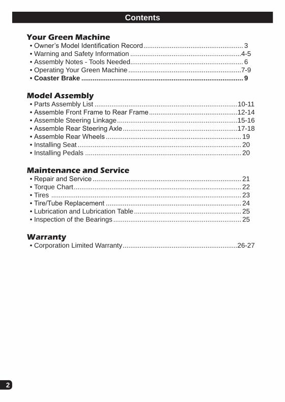
Your Green Machine• Owner’s Model Identification Record ..................................................... 3• Warning and Safety Information ...........................................................4-5• Assembly Notes - Tools Needed............................................................ 6• Operating Your Green Machine ............................................................7-9• Coaster Brake ...................................................................................... 9
Model Assembly• Parts Assembly List ............................................................................10-11• Assemble Front Frame to Rear Frame ...............................................12-14• Assemble Steering Linkage ................................................................15-16• Assemble Rear Steering Axle .............................................................17-18• Assemble Rear Wheels ........................................................................ 19• Installing Seat ....................................................................................... 20• Installing Pedals ................................................................................... 20
Maintenance and Service• Repair and Service ............................................................................... 21• Torque Chart ......................................................................................... 22• Tires ..................................................................................................... 23• Tire/Tube Replacement ........................................................................ 24• Lubrication and Lubrication Table ......................................................... 25• Inspection of the Bearings .................................................................... 25
Warranty• Corporation Limited Warranty .............................................................26-27
Contents

3
Gre
en M
achi
ne
Your Bike
Owner’s Model Identification RecordNOTE: This information is only available with model itself. It is not available from Huffy.Model number is on the packaging and instruction manual.Write the model number below to keep it for future reference.If the model is stolen, give this number and a description of the model to the police. This will help them find the model.Model Number:Purchase Date:Model Name:

4
War
ning
s an
d Sa
fety
Warning and Safety InformationPLEASE READ AND FULLY UNDERSTAND THIS OWNERS MANUAL BEFORE OPERATING THE PRODUCT
This symbol is important. See the word “CAUTION” or “WARNING” which fol-lows it.The word “CAUTION” is before mechanical instructions. If you do not obey these instructions, mechanical damage or failure of a part of the product can occur.The word “WARNING” is before personal safety instructions. If you do not obey these instructions, injury to the rider or to others can occur.
All wheeled vehicles will provide safe, enjoyable transportation and recreation when used and maintained properly. Like bicycling, skateboarding, and in-line skating, riding can be dangerous even under the best of circumstances. We do not want you to get hurt. Please follow all safety rules and operating instructions.
This toy should be used with caution since skill is required to avoid falls or collisions causing injury to the user or third parties.
WARNING - TO AVOID SERIOUS INJURY:
• CHOKING HAZARD. Small parts. Not for children under 3 years.• Adult assembly is required.• Continuous adult supervision is required.• The brake may be hot after continuous use. Do not touch after braking.• Ensure rider can reach the pedals through full range of motion.• Always wear a CPSC approved helmet while riding, with the chinstrap securely
fastened.• Always wear shoes when riding.• Ride on smooth paved surfaces. Do not ride on streets or roadways.• Always comply with local laws and regulations.• Never use near motor vehicles.• Do not ride on hills, steeply sloped areas, on or near steps, near swimming pools,
or in alleys.• Do not ride the product at dusk, at night or at times of limited visibility.• Do not ride off road, on grass or wet surfaces.• Do not ride the product over curbs or bumps that can damage the steering mecha-
nism.• Do not wear headphones or anything else that would impair your ability to hear or
see.• Do not jump or ramp product.• Do not tow the product.
continued >>

5
War
ning
s an
d Sa
fety
Warning and Safety Information - continued• Do not pull any objects with the product.• Do not push the product.• Never ride with more than one person. Maximum weight is 180 lbs (82Kg).• Excessive weight may cause a hazardous or unstable condition.• Understand all operating procedures before riding.• Do not add a motor to the product.• Do not modify the product.• Before each ride check all screws, fasteners and brakes; re-tighten any that are
loose. Replace any fasteners that are damaged.• Handlebar hand grip or tube end plugs should be replaced if damaged as bare
tubes have been known to cause injury. All products with capped handlebar ends should be checked regularly to ensure that adequate protection for the ends of the handlebars are in place.
• Replacement forks must have the same rake and tube inner diameter as the origi-nal product.
• Know your limits. Be familiar with your abilities. Use common sense. • Replace worn or broken parts immediately.• If anything does not operate properly, discontinue use.
IF YOU HAVE ANY QUESTIONS REGARDING THE OPERATION OF THIS PRODUCT, PLEASE REFER TO THIS OWNERS MANUAL OR CALL
CONSUMER SERVICE
ASSEMBLY WARNINGS:
Wheels, Tire & Axle: • The rear axle nuts must be securely
tightened to ensure rear wheels do not come loose from the axle.
• All hardware must be sufficiently tight-ened to ensure it does not come loose.
• Recommended tube/tire inflation pres-sure is on the tire sidewall.
Pivot Bolt: • Pivot bolt must be correctly and secure-
ly installed to ensure it does not come loose.
Steering Function: • Ensure the Steering Levers move freely,
front to back and all attaching hardware is securely tightened.
Seat: • Secure the seat adjustment bolts each
time the seat is moved.
Coaster Brake:• Ensure seat is adjusted so rider can
easily reach the front wheel coaster brake.

6
Ass
embl
y N
otes
Assembly Notes
Required Tools
Suggested Handling Methods:
13mm socket (supplied) Metric Allen Wrench (supplied)
Adjustable Wrench Phillips Screwdriver
Torque Wrench (recommended)
The instructions in this manual refer to the right and left side of the product, these are defined from the rider position. Do not discard any parts until the unit is com-pletely assembled.
NOTE: Check Front Tire Pressure before first ride!

7
Steering your Green Machine
Ope
ratio
nSteering Function: • Pulling back on the left lever, and pushing forward on the right lever will turn the
product towards the left. • Pulling back on the right lever, and pushing forward on the left lever will turn the
product towards the right. • Steering this product takes some practice. Ensure the rider can properly steer the
product. Practice in an open area.

8
Ope
ratio
n
WARNING: Failure to lean in the direction of the turn as shown can result in the unit rolling over.
Lean INTO a LEFT Turn Lean INTO a RIGHT Turn
Leaning into a Turn

9
Coaster Brakes
These models are equipped with a ‘coaster’ brake that is operated by rotating the crank backwards.
Operation:
Operate the coaster brake as follows:
• Push the pedal down and forward as shown.
• As you push the pedals with increasing force, the braking action of the coaster brake increases.
WARNING: Adjust Seat so that rider can fully use Coaster Brake safely.
WARNING: If you do not obey the following instructions, injury to the rider or to others can occur :
• When you ride the product the first time, test the coaster brake and practice using it at a low speed in a large level area that is free of obstruc-tions.
• Every time the product is ridden, make sure the Bolt on the Brake Arm (A) is securely attached to the Fork Mount (B). The coaster brake will not work correctly if the brake arm is loose or is not attached securely to the Fork Mount.
• Removal of Brake Arm Bolt (A) will result in brakes NOT working.
A
B
Ope
ratio
n
Forward to Pedal, Backwards to Stop

10
Part
s Vi
ew
519
19
18
18
17
16
15
21
20
11 25
224
22 1
3
4623
9
10
12
78
13
14
13
Parts Assembly View

11
Part
s Li
st
No.
Des
crip
tion
No.
Des
crip
tion
1Fo
rwar
d Fr
ame/
Fork
15La
rge
Axl
e B
olt W
ashe
r (x2
)2
Rea
r Fra
me
16Fr
ame
Bus
hing
s (x
4)3
Axl
e Fr
ame
17W
heel
Bus
hing
s (x
4)4
Cra
nk A
ssem
bly
18S
mal
l Axl
e W
ashe
r (w
ith A
xle
Bol
t x2)
(with
Axl
e R
od x
4)
5P
edal
s (le
ft / r
ight
)19
Axl
e N
ut (w
ith A
xle
Bol
t x2)
(with
Axl
e R
od x
4)6
Tire
20R
ear W
heel
(x2)
7Tu
be21
Rea
r Fai
ring
/ har
dwar
e8
Whe
el A
ssem
bly
22S
teer
ing
Fairi
ng A
ssem
bly
9S
teer
Lev
ers
(left
/ rig
ht)
23Fe
nder
/ H
ardw
are
10G
rips
(x2)
24Fr
ame
Har
dwar
e(3
Bol
ts, L
ockn
uts)
11S
teer
ing
Link
s (x
2)12
Sea
t / h
ardw
are
25Le
ft an
d R
ight
Fai
ring
Doo
rs (R
ight
sh
own)
& 4
Scr
ews
13P
ivot
Bol
t Har
dwar
e14
Axl
e B
olt o
r Rod
(x2)
Parts Assembly List

12
Ass
embl
yAssemble Front Frame to Rear Frame
B
C
A
STEPS (Recommend two persons):
CAUTION: Ensure the Steering Arms are pushed forward as shown (C).
1. Remove fairing covers if installed.2. Position the front and rear Frame Sections (A-B) as shown.3. Attach the two Frame Sections by inserting the Forward Channel (A) into the
Rear Channel (B) as shown.
Proceed to next step >>

13
Ass
embl
y
Assemble Front Frame to Rear Frame - continued
NOTE: See Torque Chart for recommended torques.
STEPS:
1. With both sections of Frame coupled (A) insert three Bolts (B) through assembly.2. Install Locknuts (C) onto three Bolts.3. Tighten evenly and securely.
B
AC
Proceed to next step >>

14
Ass
embl
yInstalling Fairing Cover Doors
STEPS:
1. Install Door (A) by inserting Tabs (B) up and under Fairing Opening (C).2. Install two Screws (D) securely. Do not over-tighten, this can damage the cover.3. Repeat for opposite side.
Applying the Fairing Decal:
1. Make sure the Fairing and Door are clean, dry and free of fingerprints.
2. Carefully remove Decal (A) from back-ing.
3. Align Decal as shown and apply slowly and evenly to avoid bubbles or wrinkles.
4. Press firmly over entire surface of Decal. - Repeat for opposite side.
A
BC
D
A

15
Ass
embl
y
Attaching Steering Linkage - Front
B
F
AE
D
C
RL
FORWARD
STEP ONE:
1. Insert end of Right Steering Rod (A) with SHORTER End (B) into Steering Rod Handle Ends (C) as shown on right side of unit.
2. Make sure Rods are on the OUTSIDE (view D) of the Steering Rods as shown and back of Rods are pointing UP (E).
3. Repeat on left side.
Proceed to next step >>
NOTE: The Steering Arms are pre-assembled at the factory. Periodically check tight-ness of Bolts/Screw (F). See Torque Table for recommended torques.

16
Attaching Steering Linkage - Rear
STEP TWO:
1. Rotate Rear Axle (A) UP 90°.2. Move Frame (B) slightly to the side.3. Insert both Steering Rods (C) into Pivot Bracket holes (D) as shown.
A
C
D
DC
1
2
B
Proceed to next step >>
Ass
embl
y

17
Assemble Rear Steering Axle
A
E
D
B
2
C1
STEP THREE:
1. Rotate Rear Axle back to horizontal, while moving Frame (A) into place between Pivot Bracket holes (B).
2. Swing the Frame (A) into the Pivot Bracket (B) so the mounting holes line up.3. Install Pivot Bolt (C) though Pivot Bracket and Rear Frame pivot end.4. Install Washer (D) and Locknut (E) onto Pivot Bolt.5. Tighten Locknut securely. See Torque Chart for recommended torque.
WARNING: Periodically check Pivot Bolt Nut for tightness. If the Pivot Bolt comes lose, damage to the product or rider injury may occur.
Ass
embl
y

18
Installing Pivot Bolt Cover
STEPS:
NOTE: Screws (C) maybe pre-installed in Rear Axle Plate (B). Remove and set aside.
1. Place Pivot Bolt Cover (A) over Rear Axle Plate (B) so that mounting holes line up.
2. Install two Screws (C) through Cover and into Rear Axle Plate.3. Install Screws securely. No not over tighten.
NOTE: Cover must be removed to check Pivot Bolt for tightness.
A
B
C
Ass
embl
y

19
Installing Rear Wheels
STEPS:
NOTE: Axle may be Bolt style or Threaded Rod style (D). Threaded Rod style will have a Washer (F) and Lock Nut (G) on both ends. Bolt Style will have a larger Washer (C) under the head of the Bolt.
1. Insert a Bushing (B) in both Wheel Axle Holes. Ensure Bushing is fully seated in the wheel. (Bushings may be pre-installed)
2. Position Wheel (A) with inset graphic facing outwards.3. If Threaded Axle Rod style (1): Place a Washer (F) and Lock Nut (G) on one
end of Axle Rod (D). Insert Axle Rod through Frame (E).4. If Bolt style (2): Place larger Washer (C) onto Axle Bolt (D) and insert Axle Bolt
through Frame (E).5. Place Wheel/Bushing assembly over end of Axle (D) making sure Bushings (B)
do not come loose.6. Install Washer (F) and Lock Nut (G) onto Axle.7. Tighten Lock Nut(s) securely. See Torque Chart for recommended torque.8. Repeat steps for opposite side wheel.
WARNING: • Ensure Axle Bolt Threads are fully through the Lock Nuts.• Ensure Wheels spin freely and evenly and are not loose side to side.
A
F G
GF
BCD2
1
ED
Ass
embl
y
20
Ass
embl
yInstalling Seat
Installing Pedals
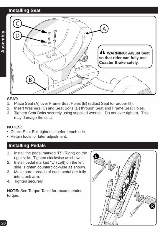
SEAT:1. Place Seat (A) over Frame Seat Holes (B) (adjust Seat for proper fit).2. Insert Washers (C) and Seat Bolts (D) through Seat and Frame Seat Holes.3. Tighten Seat Bolts securely using supplied wrench. Do not over tighten. This
may damage the seat.
NOTES: • Check Seat Bolt tightness before each ride.• Retain tools for later adjustment.
AC
D
B
WARNING: Adjust Seat so that rider can fully use Coaster Brake safely.
R
L1. Install the pedal marked “R” (Right) on the
right side. Tighten clockwise as shown.2. Install pedal marked “L” (Left) on the left
side. Tighten counterclockwise as shown.3. Make sure threads of each pedal are fully
into crank arm.4. Tighten securely.
NOTE: See Torque Table for recommended torque.

21
Maintenance and Service
Repair and Service
WARNING: • Inspect the model frequently. Failure to inspect the model and to make repairs
or adjustments, as necessary, can result in injury to the rider or to others. Make sure all parts are correctly assembled and adjusted as written in this manual and any “Special Instructions”.
• Immediately replace any damaged, missing, or badly worn parts.• Make sure all fasteners are correctly tightened as written in this manual and
any “Special Instructions”. Parts that are not tight enough can be lost or oper-ate poorly. Over tightened parts can be damaged. Make sure any replacement fasteners are the correct size and type.
NOTE: Have a bike service shop make any repairs or adjustments for which you do not have the correct tools or if the instructions in this manual or any “Special Instruc-tions” are not sufficient for you.
Mai
nten
ance

22
Mai
nten
ance
Torque ChartRecommended Torque:Use of a torque wrench is recommended. Recommended torque for each fastener is listed below. In addition to tightening to the recommended torque, please ensure the parts of the product are sufficiently tightened by performing the functional tests (in the component assembly sections of the owner’s manual) on each component as it is tightened.
NOTE: Please check that all fasteners on the product are torqued according to the table below:
Recommended Torque for clean, dry threads: How to Measure:
Fastener Size Torque (ft-lb / N•m)Screw or bolt size is determined by the width at the THREADS
as shown..157 in (4 mm) 3.1 ft-lbs (4.2 N•m)
.196 in (5 mm) 5 ft-lbs (6.8 N•m)
.236 in (6 mm) 7 ft-lb (9.5 N•m)
.275 in (7 mm) 12 ft-lbs (16.3 N•m)
.314 in (8 mm) 17 ft-lbs (23 N•m).393 in (10 mm) 33 ft-lbs (44.7 N•m)
Pedals 24 ft-lbs (30 N•m)

23
Mai
nten
ance
TiresMaintenance:• Frequently check the tire inflation pressure because all tires lose air slowly over
time. For extended storage, keep the weight of the model off the tires.• Do not use unregulated air hoses to inflate the inner tubes. An unregulated hose
can suddenly over inflate model tires and cause them to burst.• Replace worn tires.
WARNING: Do not ride or sit on the model if a tire is under inflated. This can damage the tire and inner tube.
Inflating the Tires:• Use a hand or a foot pump to inflate the tires. • Service station meter-regulated air hoses are also acceptable. • The maximum inflation pressure is shown on the tire sidewall. • If two inflation pressures are on the tire sidewall, use the higher pressure for on-
road riding and the lower pressure for off-road riding. • The lower pressure will provide better tire traction and a more comfortable ride.Before adding air to any tire, make sure the edge of the tire (the bead) is the same distance from the rim, all around the rim, on both sides of the tire. If the tire does not appear to be seated correctly, release air from the inner tube until you can push the bead of the tire into the rim where necessary. Add air slowly and stop frequently to check the tire seating and the pressure, until you reach the correct inflation pressure.
Tire Pressure TableRecommended Tire Pressure (kilopascals):Frequently check the tire inflation pressure because all tires lose air slowly over time. For extended storage, keep the weight of the product off the tires. Recommended tire pressure is marked on the side of the tire. Conversion from PSI to Kilopascals is shown here.
Tire Pressure: (PSI to Kpa Conversion)PSI Kpa20 14030 21040 27550 34560 415

24
Mai
nten
ance
Tire and Tube ReplacementSTEP 1 - Remove Existing Tire and Tube:
1 2 3
A
Steps (start opposite Filler Valve):1. Insert a Tire Lever under Tire Bead (A).2. Hook end of Tire Lever on a spoke.3. Insert second Tire Lever and slide along rim to remove tire bead.4. Remove Inner Tube and Tire.5. Inspect for cause of flat and remove any foreign object from the tire if necessary.
1. Using your hands, start with one Bead (A) of Tire (B) and install it all the way around Rim (C).
2. Insert a slightly inflated Inner Tube (D) into the Tire and make sure the Valve Stem (E) is straight and aligned with the Rim Hole.
3. Work the second Tire Bead onto the Rim all the way around. This will take a little more effort than the first Tire Bead did. Use Tire Lever Tools if needed.
4. Make sure the Tube does not get pinched between Rim and Tire.
5. Inflate Tire just enough that it takes shape.6. Double check that both Tire Beads are seated
properly and that the Valve Stem is pointing straight out.
7. Fully inflate tube to recommended pressure listed on Tire side wall - do not over-inflate.
8. Install Valve Cap.
STEP 2 - Installing New Tire and Tube:
D
A
B
C
E

25
Lubrication TableWhat When How
Pedals every six months Put four drops of oil where the axles go into the pedals.
Lubrication
WARNING: • Do not over lubricate. If oil gets on the wheel rims or the brake shoes, it will
reduce brake performance and a longer distance to stop the model will be neces-sary. Injury to the rider or to others can occur.
• Keep all oil off the surfaces of the pedals where your feet rest.• Using soap and hot water, wash all oil off the wheels, the pedals, and the tires.• Rinse with clean water and dry completely before you ride the model.• Using a light machine oil (20W), lubricate the model according to the following
table:
Inspection of the BearingsMaintenanceFrequently check the bearings of the model. Lubricate or have a bicycle service shop lubricate the bearings once a year or any time the front wheel does not spin freely and easily.Wheel BearingsLift the front wheel off the ground and slowly spin the wheel by hand. The bearings are correctly adjusted if:
• The wheel spins freely and easily.• There is no side-to-side movement at the wheel rim when you push it to the side
with light force.
Mai
nten
ance

26
Huffy Warranty
War
rant
yLimited Warranty
General:• Part or model specifi cations are subject to change without notice.• This Limited Warranty is the only warranty for this product. There are no other
expressed or implied warranties.• This Limited Warranty extends only to the original consumer and is not transferable
to anyone else.• Warranty registration is not required.• The only uses for this product are described in this manual.
What does this Limited Warranty cover?This Limited Warranty covers all parts of the product except those indicated below as not warranted.
What must you do to keep the Limited Warranty in effect?
This Limited Warranty is effective only if:• Product is completely and correctly assembled.• Product is used under normal conditions for its intended purpose (see the following
section for excluded activities).• Product receives all necessary maintenance and adjustments.• Product is used for general transportation and recreational use only.
What is not covered by this Limited Warranty?This Limited Warranty does not cover normal wear and tear, normal maintenance items, or any damage, failure, or loss that is caused by improper assembly, mainte-nance, adjustment, storage, or use of the Product.
This Limited Warranty will be void if the unit is ever:• Used in any competitive sport• Used for stunt riding, jumping, aerobatics or similar activity• Modifi ed in any way• Modifi ed with the addition of a motor• Ridden by more than one person at a time• Rented, sold, or given away• Used in a manner contrary to the instructions and warnings in this Owner’s Manual
Huffy will not be liable for incidental or consequential loss or damage, due directly or indirectly from use of this product. Some states do not allow the exclusion or limitation of incidental or consequential damages, so the above limitation may not apply to you.

27
War
rant
y
Limited Warranty -continued
What rights do you have?This warranty gives you specifi c legal rights. You may also have other rights which vary from state to state.
What will Huffy do?Huffy will replace, without charge to you, the component found to be defective by Huffy.
CONTACTING CUSTOMER SERVICE:
How do you report a problem with this product or submit a warranty claim?• Contact Consumer Service - See included list for Customer Contact information.
IN AUSTRALIA:• Contact Customer Service for Australia or New Zealand. Warranty claims can
be submitted to Huffy c/o Hunter Products Pty., Ltd., Level 2, 424 Warrigal Road, Moorabbin, Victoria 3189 Australia.
The following text is incorporated into this Limited Warranty if this product was pur-chased in Australia (but it is not incorporated if such product was purchased in New Zealand):
• Our goods come with guarantees that cannot be excluded under the Australian Consumer Law. You are entitled to a replacement or refund for a major failure and for compensation for any other reasonably foreseeable loss or damage. You are also entitled to have the goods repaired or replaced if the goods fail to be of ac-ceptable quality and the failure does not amount to a major failure.
How long does this Limited Warranty Last? • Warranty is from date of purchase.• Frame and all components are warranted for six (6) months.• Resin wheels are not warranted.

• Helmet should sit level on your head and low on your forehead• Adjust the strap sliders below the ear on both sides.• Buckle the chin strap. Adjust strap until it is snug.• No more than two fi ngers should fi t between the strap and your chin.• A proper fi tting helmet should be comfortable and not rock forward/back-
ward or side to side.• Always read the user manual that comes with your helmet to make sure it
is fi tted and attached properly to the wearer’s head according to the fi tting instructions described in the user manual.
Check www.Huffy.com for the current contact information
WARNING:ALWAYS WEAR YOUR
HELMET WHEN RIDING THIS PRODUCT!