Embed Size (px)
Citation preview
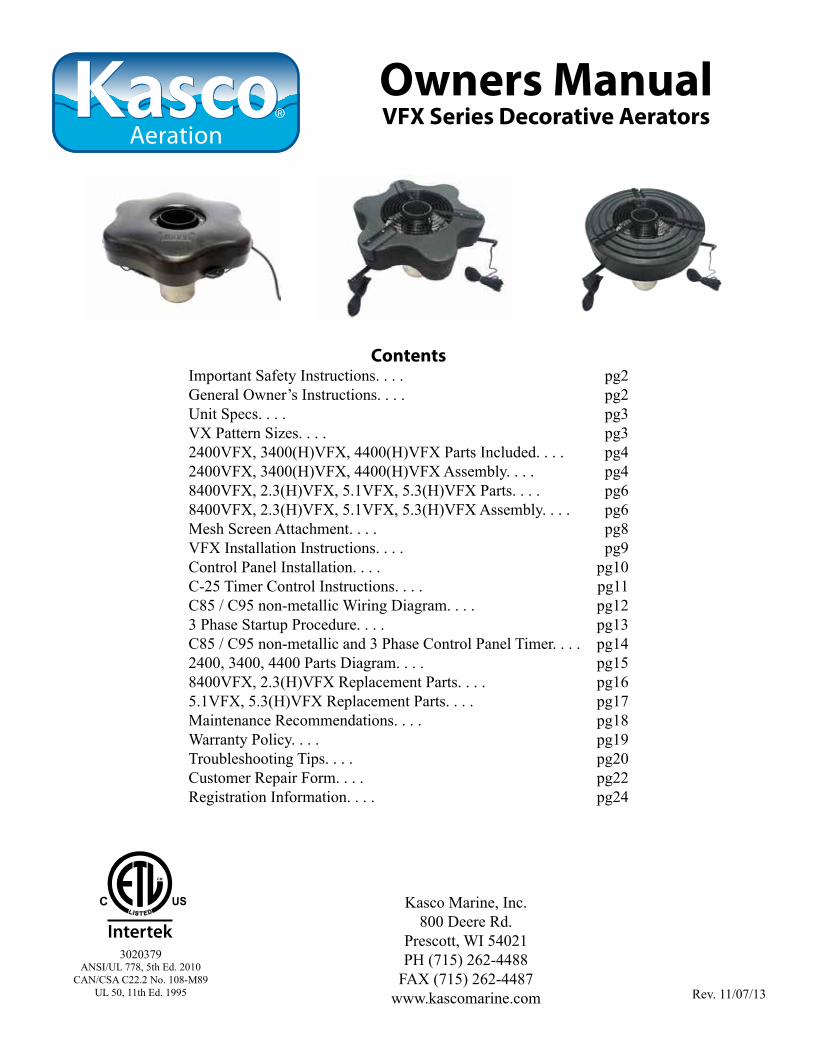
Owners ManualVFX Series Decorative Aerators
ContentsImportant Safety Instructions. . . . pg2General Owner’s Instructions. . . . pg2Unit Specs. . . . pg3VX Pattern Sizes. . . . pg32400VFX, 3400(H)VFX, 4400(H)VFX Parts Included. . . . pg42400VFX, 3400(H)VFX, 4400(H)VFX Assembly. . . . pg48400VFX, 2.3(H)VFX, 5.1VFX, 5.3(H)VFX Parts. . . . pg68400VFX, 2.3(H)VFX, 5.1VFX, 5.3(H)VFX Assembly. . . . pg6Mesh Screen Attachment. . . . pg8VFX Installation Instructions. . . . pg9Control Panel Installation. . . . pg10C-25 Timer Control Instructions. . . . pg11C85 / C95 non-metallic Wiring Diagram. . . . pg123 Phase Startup Procedure. . . . pg13C85 / C95 non-metallic and 3 Phase Control Panel Timer. . . . pg142400, 3400, 4400 Parts Diagram. . . . pg158400VFX, 2.3(H)VFX Replacement Parts. . . . pg165.1VFX, 5.3(H)VFX Replacement Parts. . . . pg17Maintenance Recommendations. . . . pg18Warranty Policy. . . . pg19Troubleshooting Tips. . . . pg20Customer Repair Form. . . . pg22Registration Information. . . . pg24
Rev. 11/07/13
Kasco Marine, Inc.800 Deere Rd.
Prescott, WI 54021PH (715) 262-4488
FAX (715) 262-4487www.kascomarine.com
C
Intertek3020379
ANSI/UL 778, 5th Ed. 2010CAN/CSA C22.2 No. 108-M89
UL 50, 11th Ed. 1995
2
THANKSWe at Kasco Marine, Inc. would like to both thank and congratulate you on your purchase of the VFX model aerator. We appreciate you choosing Kasco and for your purchase. Your decision to purchase Kasco’s VFX model Aerator will not disappoint you. The VFX model Aerator will be a great addition to your body of water. It will help improve the water quality by adding much needed oxygen and circulation. It will also enhance the aesthetics of the pond or lake with a beautiful pattern. The lighting package (if purchased) will illuminate your aerator for beauty at night. We thank you for choosing Kasco for your aerator needs and want you to be completely satisfied with your purchase.
Important Safety Instructions
Please read and follow these extremely important safety and handling instructions for your Kasco equip-ment. Following these instructions will help ensure your safety and the quality performance of your equip-ment.
• Under NO circumstances should anyone enter the water with the electrical equipment plugged in and/or in operation. All Kasco equipment is ETL approved to UL and CSA standards for safety in water. However, it is NEVER recommended to enter the water with the equipment in operation.
• Caution should be used when dealing with any electrical equipment with moving parts.
• NEVER run the unit out of water. It will damage the seals and create a dangerous situation for the operator.
• Extreme caution should be used around water, especially cold water, such as in Spring, Fall, and Winter, which poses a hazard in and of itself.
• NEVER lift or drag the aerator by the power or light cord. If you need to pull the unit to the side of the pond, use the anchoring ropes.
• Do not use waders in deep ponds/lakes or ponds/lakes with drop-offs, drastic slopes, or soft bottom material.
• Do not use boats that tip easily for aerator installa-tion, such as a canoe, and follow all boating safety rules and regulations, including wearing a PFD. (Personal Flotation Device)
• Single phase aerators are supplied with an inter-
nal grounding conductor and/or a grounding-type attachment plug. To reduce the risk of electrical shock, be certain the aerator is properly connected to the Kasco supplied control panel. (refer to the C-25, C-85 & C-95 Control instructions)
• 3 phase aerators (2.3VFX, 5.3VFX) require a startup test after wiring to ensure proper rotation of the propeller. If the propeller is rotating in the op-posite direction, the unit will not perform properly and internal damage to the unit may occur. (See 3 phase startup procedure)
• Control panels must be installed a minimum of 5ft(3m in Canada) from the inside wall of the pond, unless separated from the body of water by a fence wall, or other permanent barrier that will make the unit inaccessible to persons in the water.
• Control panels must be installed by a qualified electrician.
• Ground Fault Circuit Interrupters (GFCI) should be tested upon each installation and every month thereafter to ensure proper operation.
General Owner’s Instructions
INSPECT THE SHIPMENTImmediately inspect your Kasco Aerator shipment for any visible damages. Also cross reference the parts supplied with the Parts Included sheet to check for shortages. Shortages should be reported immediately to your Kasco Marine distributor or representative and damages reported to your carrier and Kasco Marine.
CAUTIONWARNING: Under NO circumstances should anyone enter the water with the unit in operation. Always operate the unit in the water and keep people and ob-jects clear of the propeller. Do not lift or pull the unit by the electrical cord. Always use extreme caution around electrical equipment and water situations.
ASSEMBLY & INSTALLATIONPlease see the proper Assembly and Installation In-structions enclosed in this manual. Each is specific for your model and size of aerator. Note: Use a nylon tie to help keep the power cords for the unit and lights free of the propeller by tying each cord to either side of the float. If you have a light kit, make sure that the unit cord is tied to one side of the float and the light cord to the other for balance. Note: It is extremely
3
Unit SpecsModel Voltage Amps Lock
rotor amps
Control box con-nection
Aerator connec-
tionsingle phase aerators
2400VFX 110-120 5.6 12 C-25 plug in
Plug into C-25
3400VFX 110-120 7.3 18 C-25 plug in
Plug into C-25
3400HVFX 208-240 3.7 9 Hardwire C-85
plug into or hard-wire C85
4400VFX 110-120 11.3 40 C-25 plug in
Plug into C-25
4400HVFX 208-240 5.7 20 Hardwire C-85
plug into or hard-wire C85
8400VFX 208-240 11 40 Hardwire C-85
plug into or hard-wire C85
5.1VFX 208-240 20 97 Hardwire C-95
hardwire C95
3 phase aerators2.3VFX 208 7.5 40 see your control
panel instructions5.3VFX 208 16.0 100
2.3HVFX 460 3.6 24 see your control panel instructions5.3HVFX 460 7.8 49
VX Pattern Sizes
NOTE: Pattern sizes listed are approximate. Varia-tions in voltage caused by regional electrical differenc-es or voltage drop due to long power cords may result in reduced pattern sizes.
Model Height Width2400VFX 5’ 15’3400VFX 5.5’ 21’
3400HVFX 5.5’ 21’4400VFX 8’ 26’
4400HVFX 8’ 26’8400VFX / 2.3(H)VFX 8’ 32’5.1VFX / 5.3(H)VFX 10’ 34’
important to test the GFI breaker in the control panel upon each installation/reinstallation of the unit to en-sure proper functioning.
WARRANTYKasco aerators are the result of over 35 years of design and engineering. Kasco products are built to with-stand the toughest conditions. Kasco Marine backs each VFX model aerator with either a 2 Year or 3 Year Warranty depending on the model. This warranty cov-ers any and all manufacturers defects within the war-ranty period from the date of purchase (See Warranty Section). Please register your aerator online at:www.kascomarine.com (under the technical tab)
USE AND OPERATIONKasco aerators are designed and engineered for con-tinuous duty, such as on fish farms or other aquacul-ture applications, or on-demand use, as needed in a recreational water feature.
During flotation operation, the water is pulled from 360O around the unit and from below the unit. The water is pulled upward and thrust through the flotation collar into the air.
Your Kasco Marine aerator is ready for immediate use (after installation). Make sure to keep the motor hous-ing clean from hard water deposits and/or algae. (See Maintenance Recommendations.)
It is extremely important that proper and sufficient voltage is supplied to the aerator motor. Unit should be protected by a GFCI. Control panels must be installed by a qualified electrician. (See Installation instructions).
Kasco aerators are lightweight, energy efficient, and easy to install and operate. We strive to produce prod-ucts that exceed customer expectations. We hope you enjoy your Kasco aerator.
UNIT STORAGEWhen storing units during the offseason, it is impor-tant to store them upside down if they are going to be sitting for long periods of time. Units that sit upright on a shelf for many months, or even years have a greater likelihood of seals drying out. Storing upside down will ensure oil is lubricating the seals and pre-vent drying.
4
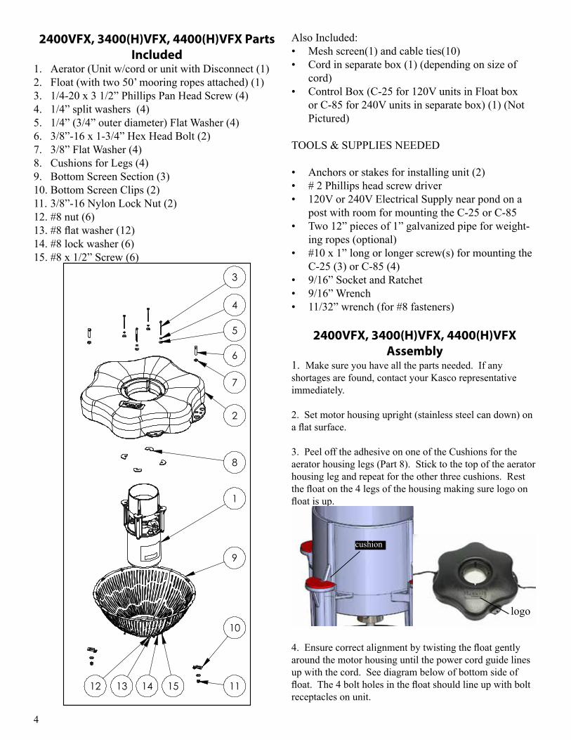
Also Included:• Mesh screen(1) and cable ties(10)• Cord in separate box (1) (depending on size of
cord)• Control Box (C-25 for 120V units in Float box
or C-85 for 240V units in separate box) (1) (Not Pictured)
TOOLS & SUPPLIES NEEDED
• Anchors or stakes for installing unit (2)• # 2 Phillips head screw driver • 120V or 240V Electrical Supply near pond on a
post with room for mounting the C-25 or C-85 • Two 12” pieces of 1” galvanized pipe for weight-
ing ropes (optional)• #10 x 1” long or longer screw(s) for mounting the
C-25 (3) or C-85 (4)• 9/16” Socket and Ratchet • 9/16” Wrench• 11/32” wrench (for #8 fasteners)
2400VFX, 3400(H)VFX, 4400(H)VFX Assembly
1. Make sure you have all the parts needed. If any shortages are found, contact your Kasco representative immediately.
2. Set motor housing upright (stainless steel can down) on a flat surface.
3. Peel off the adhesive on one of the Cushions for the aerator housing legs (Part 8). Stick to the top of the aerator housing leg and repeat for the other three cushions. Rest the float on the 4 legs of the housing making sure logo on float is up.
cushion
logo
4. Ensure correct alignment by twisting the float gently around the motor housing until the power cord guide lines up with the cord. See diagram below of bottom side of float. The 4 bolt holes in the float should line up with bolt receptacles on unit.
2400VFX, 3400(H)VFX, 4400(H)VFX Parts Included
1. Aerator (Unit w/cord or unit with Disconnect (1)2. Float (with two 50’ mooring ropes attached) (1)3. 1/4-20 x 3 1/2” Phillips Pan Head Screw (4)4. 1/4” split washers (4)5. 1/4” (3/4” outer diameter) Flat Washer (4)6. 3/8”-16 x 1-3/4” Hex Head Bolt (2)7. 3/8” Flat Washer (4)8. Cushions for Legs (4)9. Bottom Screen Section (3)10. Bottom Screen Clips (2)11. 3/8”-16 Nylon Lock Nut (2)12. #8 nut (6)13. #8 flat washer (12)14. #8 lock washer (6)15. #8 x 1/2” Screw (6)
1
2
3
4
5
6
7
8
9
12
10
1113 14 15
REV. ECO# DESCRIPTION DR'N BY DATE DES ENG CH'K BY
1 INITIAL RELEASE
XXXX-XXXX-XX
DO NOT SCALE DRAWINGC.A.D. GENERATED DRAWING
800 DEERE ROADPRESCOTT, WI 54021-1241
XFX FLOAT ASSEMBLY W/SCREEN
XX
XX
THIS DRAWING CONTAINS PROPRIETARYINFORMATION AND SHALL NOT BE USED,REPRODUCED OR DISTRIBUTED WITHOUT
THE PRIOR WRITTEN CONSENT OFKASCO MARINE, INCORPORATED
.X .02 [.508] .XX .010 [.254]
.XXX .005 [.127] ANGULAR 0.5
UNLESS OTHERWISE SPECIFIEDDIMENSIONS ARE IN INCHES.
DIMENSIONS IN [ ] ARE MILLIMETERS. TOLERANCES ON:THIS DOCUMENT HAS BEEN ISSUED
FOR ENGINEERING INFORMATIONALPURPOSES ONLY. ANY REVISIONS
TO THE CONTENT OF THIS DOCUMENTMUST BE INCORPORATED INTO THE
ORIGINAL CAD FILE.
THIRD ANGLE PROJECTION TITLE:
XXXX-XXXX-XXSHEET 1 OF 1
FINISH:
MATERIAL:
SCALE: 1:24
DWG. NO.
5
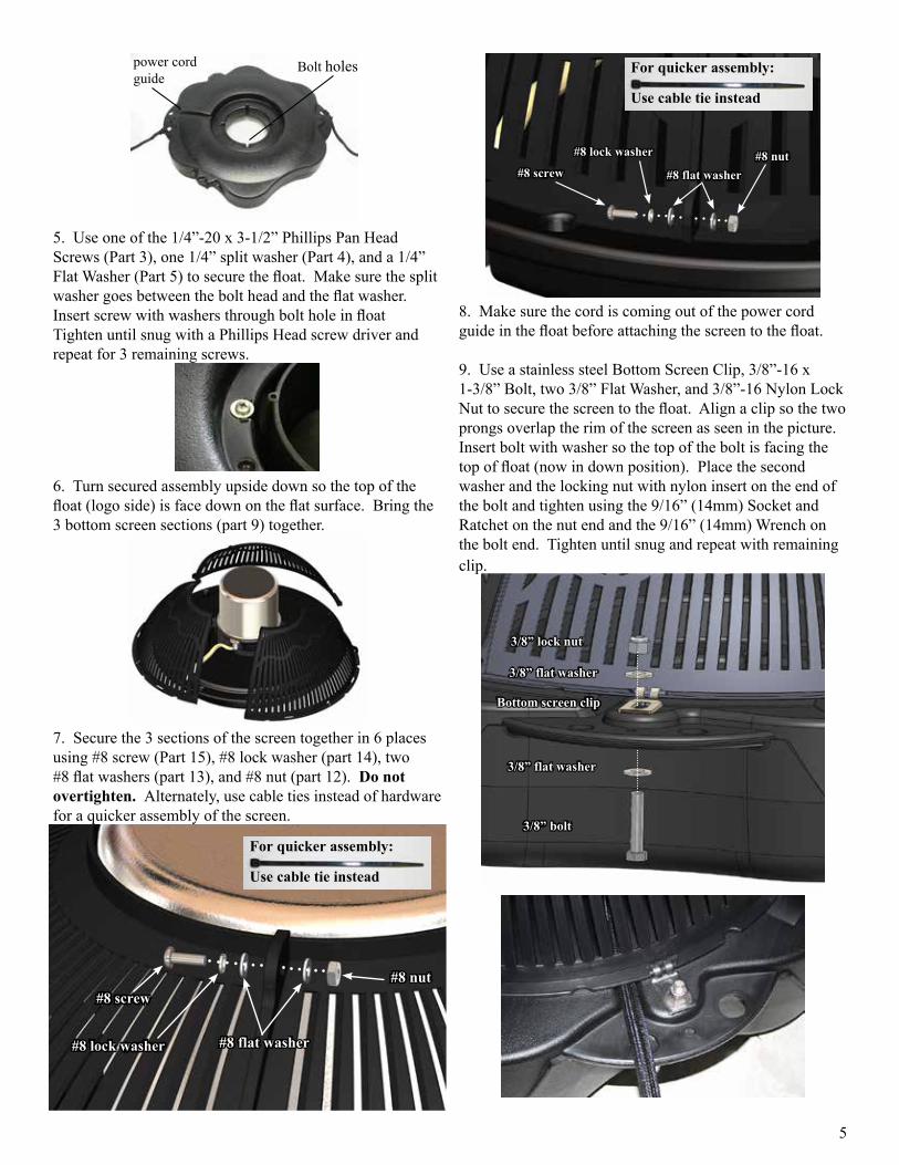
#8 screw
#8 lock washer
#8 flat washer#8 nut
For quicker assembly:
Use cable tie instead
8. Make sure the cord is coming out of the power cord guide in the float before attaching the screen to the float.
9. Use a stainless steel Bottom Screen Clip, 3/8”-16 x 1-3/8” Bolt, two 3/8” Flat Washer, and 3/8”-16 Nylon Lock Nut to secure the screen to the float. Align a clip so the two prongs overlap the rim of the screen as seen in the picture. Insert bolt with washer so the top of the bolt is facing the top of float (now in down position). Place the second washer and the locking nut with nylon insert on the end of the bolt and tighten using the 9/16” (14mm) Socket and Ratchet on the nut end and the 9/16” (14mm) Wrench on the bolt end. Tighten until snug and repeat with remaining clip.
3/8” lock nut
3/8” flat washer
Bottom screen clip
3/8” flat washer
3/8” bolt
Bolt holespower cordguide
5. Use one of the 1/4”-20 x 3-1/2” Phillips Pan Head Screws (Part 3), one 1/4” split washer (Part 4), and a 1/4” Flat Washer (Part 5) to secure the float. Make sure the split washer goes between the bolt head and the flat washer. Insert screw with washers through bolt hole in float Tighten until snug with a Phillips Head screw driver and repeat for 3 remaining screws.
6. Turn secured assembly upside down so the top of the float (logo side) is face down on the flat surface. Bring the 3 bottom screen sections (part 9) together.
7. Secure the 3 sections of the screen together in 6 places using #8 screw (Part 15), #8 lock washer (part 14), two #8 flat washers (part 13), and #8 nut (part 12). Do not overtighten. Alternately, use cable ties instead of hardware for a quicker assembly of the screen.
#8 screw
#8 lock washer #8 flat washer
#8 nut
For quicker assembly:
Use cable tie instead
6
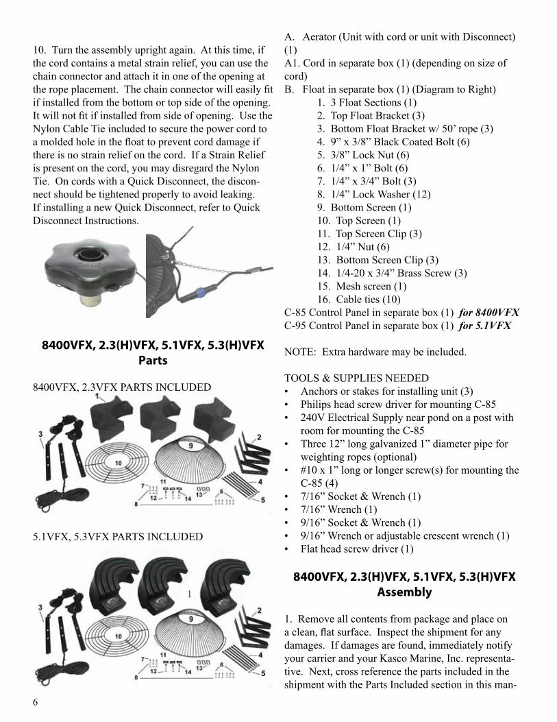
A. Aerator (Unit with cord or unit with Disconnect) (1)A1. Cord in separate box (1) (depending on size of cord)B. Float in separate box (1) (Diagram to Right) 1. 3 Float Sections (1) 2. Top Float Bracket (3) 3. Bottom Float Bracket w/ 50’ rope (3) 4. 9” x 3/8” Black Coated Bolt (6) 5. 3/8” Lock Nut (6) 6. 1/4” x 1” Bolt (6) 7. 1/4” x 3/4” Bolt (3) 8. 1/4” Lock Washer (12) 9. Bottom Screen (1) 10. Top Screen (1) 11. Top Screen Clip (3) 12. 1/4” Nut (6) 13. Bottom Screen Clip (3) 14. 1/4-20 x 3/4” Brass Screw (3) 15. Mesh screen (1) 16. Cable ties (10)C-85 Control Panel in separate box (1) for 8400VFXC-95 Control Panel in separate box (1) for 5.1VFX
NOTE: Extra hardware may be included.
TOOLS & SUPPLIES NEEDED• Anchors or stakes for installing unit (3)• Philips head screw driver for mounting C-85 • 240V Electrical Supply near pond on a post with
room for mounting the C-85 • Three 12” long galvanized 1” diameter pipe for
weighting ropes (optional)• #10 x 1” long or longer screw(s) for mounting the
C-85 (4)• 7/16” Socket & Wrench (1)• 7/16” Wrench (1)• 9/16” Socket & Wrench (1)• 9/16” Wrench or adjustable crescent wrench (1)• Flat head screw driver (1)
8400VFX, 2.3(H)VFX, 5.1VFX, 5.3(H)VFX Assembly
1. Remove all contents from package and place on a clean, flat surface. Inspect the shipment for any damages. If damages are found, immediately notify your carrier and your Kasco Marine, Inc. representa-tive. Next, cross reference the parts included in the shipment with the Parts Included section in this man-
10. Turn the assembly upright again. At this time, if the cord contains a metal strain relief, you can use the chain connector and attach it in one of the opening at the rope placement. The chain connector will easily fit if installed from the bottom or top side of the opening. It will not fit if installed from side of opening. Use the Nylon Cable Tie included to secure the power cord to a molded hole in the float to prevent cord damage if there is no strain relief on the cord. If a Strain Relief is present on the cord, you may disregard the Nylon Tie. On cords with a Quick Disconnect, the discon-nect should be tightened properly to avoid leaking. If installing a new Quick Disconnect, refer to Quick Disconnect Instructions.
8400VFX, 2.3(H)VFX, 5.1VFX, 5.3(H)VFX Parts
8400VFX, 2.3VFX PARTS INCLUDED
5.1VFX, 5.3VFX PARTS INCLUDED
7
4. Turn the assembly upside down and place the Bot-tom Float Brackets (Part #B3) over the bolts, the ends of which should now be extending through the assem-bly. Loosely install the six 3/8” Lock Nuts (Part #B5) on the ends of the bolts (do not tighten yet). Connect the Top and Bottom Float Brackets using three 1/4” x 3/4” Bolts (Part #B7) with three 1/4” Lock Washers (Part #B8) and three 1/4” Nuts (Part #B12) and tighten using the 7/16” wrench and socket.
8400, 2.3 5.1, 5.3
5. Stand the assembly on its side and center the Top Screen (Part #B10) inside the three Top Float Brack-ets. Attach the screen by spanning each Top Screen Clip (Part #B11) across the two innermost rings on the screen and the hole in the float bracket. Insert the 3/4” Brass Screws (Part #B14) and attach with 1/4” Lock Washers and 1/4” Nuts to secure the screen to the float assembly.
6. Return the assembly to the upside down position and place the motor assembly (Stainless Steel can side up, black tube down) in the center of the float. Align the 3 taller legs of the black aerator tube with the 3 float brackets. Attach the motor to the float using the 1/4” x 1” bolts (Part #B6). Attach to the float bracket using the two middle holes of the float bracket. Tight-en using the 1/4” x 1” Bolts with 1/4” Lock Washers using the 7/16” socket and wrench. The 1” bolts will screw directly into the legs of the black aerator tube.
ual. Make sure you have all the parts needed. If any shortages are found, contact your Kasco representative immediately.
2. Arrange the three Float Sections (Part #B1) upright (plug on bottom) so the overlap of one section aligns with the next section and loosely push the three sec-tions together to form a continuous ring.
8400, 2.3
5.1, 5.3Float Up (plug) Float Down
8400, 2.3 5.1, 5.3
3. Position one Top Float Bracket (Part #B2) so that the bolt holes in the bracket align with the bolt holes in the two adjoined float sections and insert two 9” Coated Bolts (Part #B4) through the assembly. This may require some minor repositioning of the float sec-tions as you push the bolt all the way through. Do not force the bolt through. Repeat for the remaining two joints.
8400, 2.3 5.1, 5.3
8
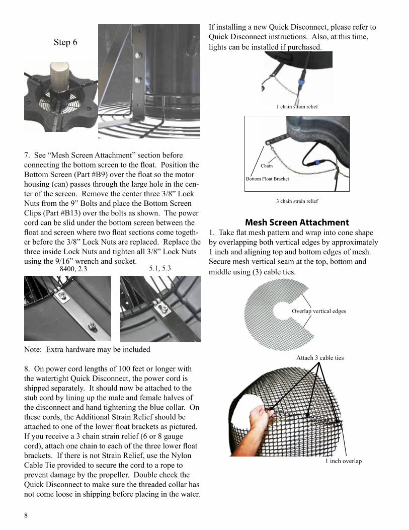
If installing a new Quick Disconnect, please refer to Quick Disconnect instructions. Also, at this time, lights can be installed if purchased.
1 chain strain relief
Bottom Float Bracket
Chain
3 chain strain relief
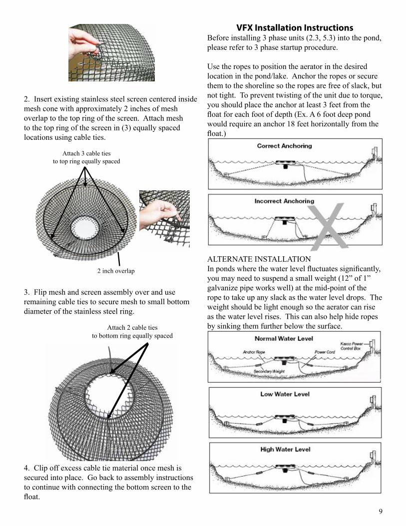
Mesh Screen Attachment1. Take flat mesh pattern and wrap into cone shape by overlapping both vertical edges by approximately 1 inch and aligning top and bottom edges of mesh. Secure mesh vertical seam at the top, bottom and middle using (3) cable ties.
Overlap vertical edges
1 inch overlap
Attach 3 cable ties
Step 6
7. See “Mesh Screen Attachment” section before connecting the bottom screen to the float. Position the Bottom Screen (Part #B9) over the float so the motor housing (can) passes through the large hole in the cen-ter of the screen. Remove the center three 3/8” Lock Nuts from the 9” Bolts and place the Bottom Screen Clips (Part #B13) over the bolts as shown. The power cord can be slid under the bottom screen between the float and screen where two float sections come togeth-er before the 3/8” Lock Nuts are replaced. Replace the three inside Lock Nuts and tighten all 3/8” Lock Nuts using the 9/16” wrench and socket.
8400, 2.3 5.1, 5.3
Note: Extra hardware may be included
8. On power cord lengths of 100 feet or longer with the watertight Quick Disconnect, the power cord is shipped separately. It should now be attached to the stub cord by lining up the male and female halves of the disconnect and hand tightening the blue collar. On these cords, the Additional Strain Relief should be attached to one of the lower float brackets as pictured. If you receive a 3 chain strain relief (6 or 8 gauge cord), attach one chain to each of the three lower float brackets. If there is not Strain Relief, use the Nylon Cable Tie provided to secure the cord to a rope to prevent damage by the propeller. Double check the Quick Disconnect to make sure the threaded collar has not come loose in shipping before placing in the water.
9
VFX Installation InstructionsBefore installing 3 phase units (2.3, 5.3) into the pond, please refer to 3 phase startup procedure.
Use the ropes to position the aerator in the desired location in the pond/lake. Anchor the ropes or secure them to the shoreline so the ropes are free of slack, but not tight. To prevent twisting of the unit due to torque, you should place the anchor at least 3 feet from the float for each foot of depth (Ex. A 6 foot deep pond would require an anchor 18 feet horizontally from the float.)
ALTERNATE INSTALLATIONIn ponds where the water level fluctuates significantly, you may need to suspend a small weight (12” of 1” galvanize pipe works well) at the mid-point of the rope to take up any slack as the water level drops. The weight should be light enough so the aerator can rise as the water level rises. This can also help hide ropes by sinking them further below the surface.
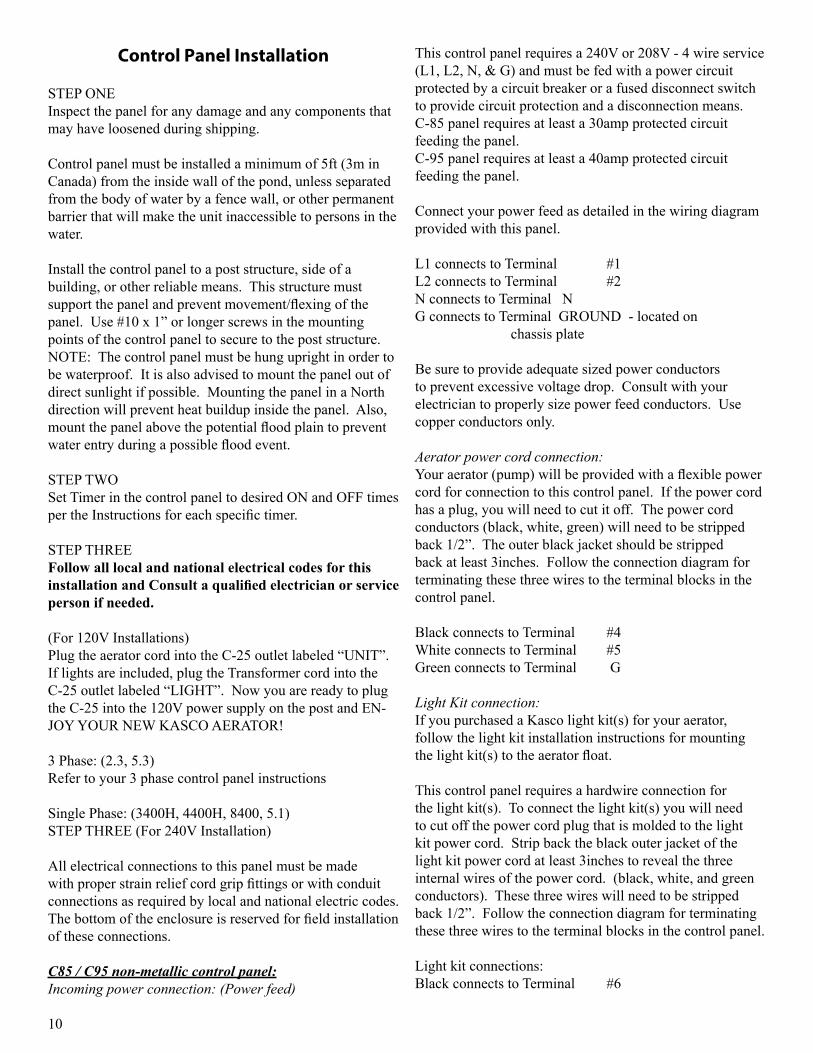
2. Insert existing stainless steel screen centered inside mesh cone with approximately 2 inches of mesh overlap to the top ring of the screen. Attach mesh to the top ring of the screen in (3) equally spaced locations using cable ties.
Attach 3 cable tiesto top ring equally spaced
2 inch overlap
3. Flip mesh and screen assembly over and use remaining cable ties to secure mesh to small bottom diameter of the stainless steel ring.
Attach 2 cable tiesto bottom ring equally spaced
4. Clip off excess cable tie material once mesh is secured into place. Go back to assembly instructions to continue with connecting the bottom screen to the float.
10
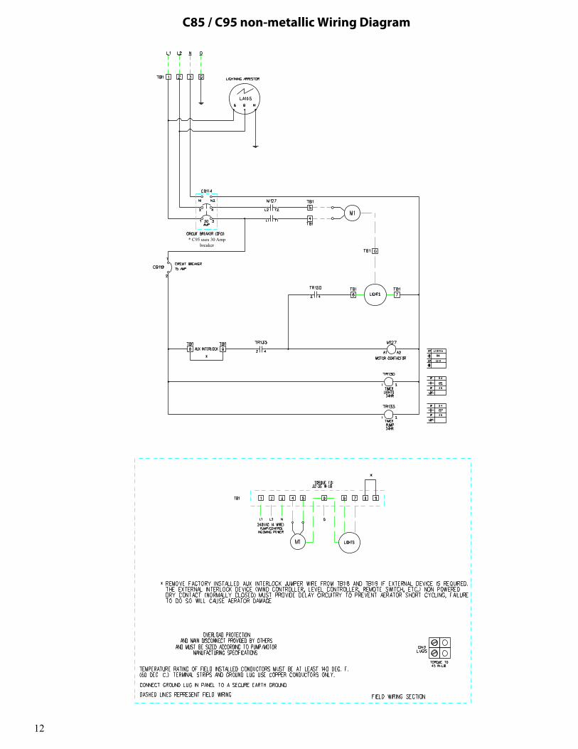
This control panel requires a 240V or 208V - 4 wire service (L1, L2, N, & G) and must be fed with a power circuit protected by a circuit breaker or a fused disconnect switch to provide circuit protection and a disconnection means.C-85 panel requires at least a 30amp protected circuit feeding the panel.C-95 panel requires at least a 40amp protected circuit feeding the panel.
Connect your power feed as detailed in the wiring diagram provided with this panel.
L1 connects to Terminal #1L2 connects to Terminal #2N connects to Terminal NG connects to Terminal GROUND - located on chassis plate
Be sure to provide adequate sized power conductors to prevent excessive voltage drop. Consult with your electrician to properly size power feed conductors. Use copper conductors only.
Aerator power cord connection:Your aerator (pump) will be provided with a flexible power cord for connection to this control panel. If the power cord has a plug, you will need to cut it off. The power cord conductors (black, white, green) will need to be stripped back 1/2”. The outer black jacket should be stripped back at least 3inches. Follow the connection diagram for terminating these three wires to the terminal blocks in the control panel.
Black connects to Terminal #4White connects to Terminal #5Green connects to Terminal G
Light Kit connection:If you purchased a Kasco light kit(s) for your aerator, follow the light kit installation instructions for mounting the light kit(s) to the aerator float.
This control panel requires a hardwire connection for the light kit(s). To connect the light kit(s) you will need to cut off the power cord plug that is molded to the light kit power cord. Strip back the black outer jacket of the light kit power cord at least 3inches to reveal the three internal wires of the power cord. (black, white, and green conductors). These three wires will need to be stripped back 1/2”. Follow the connection diagram for terminating these three wires to the terminal blocks in the control panel.
Light kit connections:Black connects to Terminal #6
Control Panel Installation
STEP ONEInspect the panel for any damage and any components that may have loosened during shipping.
Control panel must be installed a minimum of 5ft (3m in Canada) from the inside wall of the pond, unless separated from the body of water by a fence wall, or other permanent barrier that will make the unit inaccessible to persons in the water.
Install the control panel to a post structure, side of a building, or other reliable means. This structure must support the panel and prevent movement/flexing of the panel. Use #10 x 1” or longer screws in the mounting points of the control panel to secure to the post structure. NOTE: The control panel must be hung upright in order to be waterproof. It is also advised to mount the panel out of direct sunlight if possible. Mounting the panel in a North direction will prevent heat buildup inside the panel. Also, mount the panel above the potential flood plain to prevent water entry during a possible flood event.
STEP TWOSet Timer in the control panel to desired ON and OFF times per the Instructions for each specific timer.
STEP THREE Follow all local and national electrical codes for this installation and Consult a qualified electrician or service person if needed.
(For 120V Installations)Plug the aerator cord into the C-25 outlet labeled “UNIT”. If lights are included, plug the Transformer cord into the C-25 outlet labeled “LIGHT”. Now you are ready to plug the C-25 into the 120V power supply on the post and EN-JOY YOUR NEW KASCO AERATOR!
3 Phase: (2.3, 5.3)Refer to your 3 phase control panel instructions
Single Phase: (3400H, 4400H, 8400, 5.1)STEP THREE (For 240V Installation)
All electrical connections to this panel must be made with proper strain relief cord grip fittings or with conduit connections as required by local and national electric codes. The bottom of the enclosure is reserved for field installation of these connections.
C85 / C95 non-metallic control panel:Incoming power connection: (Power feed)
11
2. If the G.F.C.I. tests okay, restore power by pushing the RESET button back in. THE RESET BUT-TON MUST BE PUSHED FIRMLY AND FULLY INTO PLACE UNTIL IT LOCKS AND RE-MAINS DE-PRESSED AFTER PRESSURE HAS BEEN REMOVED. DANGER: IF RESET BUTTON DOES NOT POP OUT, IF TEST LAMP REMAINS LIT WHEN RESET BUTTON DOES POP OUT, OR IF THE G.F.C.I. FAILS TO RESET PROPERLY, DO NOT USE TIMER! CONTACT A QUALIFIED SERVICE TECHNICIAN!
Failure to use the C-25 with Kasco aerators will void the warranty and cause the aerator to not be listed to UL and CSA standards via ETL.
UNDER NO CIRCUMSTANCES SHOULD ANYONE ENTER THE WATER WHEN A UNIT IS IN OPERA-TION!
TIMER-OPERATION INSTRUCTIONSC-25 Control Box will turn the aerator ON & OFF with the TIMER. Kasco lights will turn ON with the PHOTO EYE and OFF with TIMER. C-25 Control Box is to be used with Kasco Approved Lights ONLY! • Insert “ON” (GREEN) and “OFF” (RED) trippers into
dial at desired ON and OFF times.• Turn dial clockwise one or more revolutions until
correct time-of-day (AM or PM) in window is aligned with the arrow.
• Plug aerator cord into the RIGHT hand outlet (labeled UNIT).
• Plug transformer light cord into LEFT hand outlet (labeled LIGHT).
FOR TEMPORARY MANUAL OPERATIONRotate MANUAL knob counter-clockwise to desired ON or OFF position. Timer will follow next automatic operation.
White connects to Terminal #7Green connects to Terminal G
STEP FOUR:Test the GFCB with the test button now and every 30 days.
If lights are installed, they can now be installed per Instruc-tions included with the lights.Once completed, power can be restored to the panel.
Record the following data while the Aerator is operating in the water under load:
Voltage:
L1-L2 ________
L1-N _________
L2-N _________
Amperage:
L1 __________
L2 __________
Date installed _____/_____/_____ Any unauthorized modifications to this control panel will void the UL listing and the Kasco warranty.
C-25 Timer Control InstructionsIMPORTANTThis portable timer is designed for CONTROLLING the connected equipment only. Unplug timer before servic-ing the unit or the equipment it controls. THE MANUAL OVERRIDE KNOB IS NOT TO BE USED AS A POWER DISCONNECT! For maximum protection against electri-cal shock hazard, perform test procedure on G.F.C.I. at least once a month. Mount at least 5 ft. from open water.
G.F.C.I. TEST PROCEDUREThe G.F.C.I. should be checked every month to make sure that it is operating properly. Just follow the simple instruc-tions below. It is recommended to maintain a maintenance diary of your monthly safety check. 1. Push TEST button, RESET button should pop out from inner surface. This should result in power being OFF at the outlet protected by the G.F.C.I. Verify by plugging a test lamp into the outlet. Be sure the timer is in the ON position.
12
C85 / C95 non-metallic Wiring Diagram
* C95 uses 30 Amp breaker
13
3 Phase Startup Procedure
If a Kasco Control Panel is not provided, please refer to the following warnings:
When inherent overheating protection is not provided: use with approved motor control that matches motor input in full load amperes with overload element(s) selected or adjusted in accordance with control instructions. Utiliser un démarreur approuvé convenant au courant à pleine charge du moteur et dont les éléments thermiques sont réglés ou choisis conformément aux instructions qui l’accompagnent.
When inherent overheating protection is provided: use with approved motor control that matches motor input in full load amperes. See table below.Utiliser un démarreur approuvé convenant au courant à pleine charge du moteur.
Note: The motor input in full load amperes is the marked value or the service factor amperes, shown on the namplate.
3 phase 208-230 Volt
2.3VFX 5.3VFX
Full load amps 7.5 16
3 phase 460 Volt
2.3HVFX 5.3HVFX
Full load amps 3.6 7.8
Control panels must be installed by a qualified electri-cian.
If unit is connected to a circuit protected by a fuse, use a time-delay fuse with this pump.
You must verify motor rotation before installing the unit in the water. 3phase Kasco units will run in a clockwise rotation when looking down at the propeller. Stand clear of the propeller while verifying rotation. If a Kasco 3 phase panel is supplied, follow the intructions with the panel. Also follow the steps below.
Electrician:1. Verify all screw terminal connections are tightened to
specified torque setting prior to energizing the panel.
2. Verify the electrical service (voltage and Phase) matches the control panel and aerator nameplates ratings. Refer to the control panel instructions and schematics for installation details.
3. Verify all switches, circuit breakers, and motor starters are in the OFF position
4. Connect electrical service to this control panel as shown in the electrical schematic that came with the panel.
5. Connect the aerator power cord to this panel as shown in the electrical schematic.
6. Set the motor starter overload to the FLA rating on the aerator nameplate.
7. Pump rotation: The pump rotation is clockwise when looking down at the propeller. Apply power to the control panel. Turn on the 15amp control circuit breaker, and motor starter.
8. Momentarily turn the Hand-Off-Auto switch to Hand. This will run the aerator. Do not run the aerator for more than a few seconds on shore. If the rotation is not correct. Disconnect and lock out power from the control panel. Swap any two of the aerator power cord wires in the panel. This will cause the motor to reverse direction. Reapply power to the panel and verify the rotation is clockwise.
9. Once rotation is verified, with the power disconnected and locked out again, continue with installation of the aerator as detailed in the aerator owner’s manual.
Record the following data while the unit is operating in the water under load:
Voltage: Amperage:
L1-L2 ____________ L1_______________
L1-L3 ____________ L2_______________
L2-L3 ____________ L3_______________
Current unbalance should not exceed 5% at full load
14
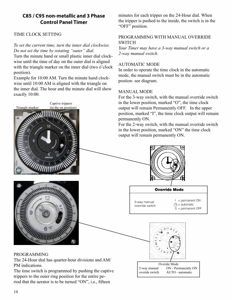
minutes for each tripper on the 24-Hour dial. When the tripper is pushed to the inside, the switch is in the “OFF” position.
PROGRAMMING WITH MANUAL OVERRIDE SWITCH Your Timer may have a 3-way manual switch or a 2-way manual switch.
AUTOMATIC MODE In order to operate the time clock in the automatic mode, the manual switch must be in the automatic postion- see diagram.
MANUAL MODE For the 3-way switch, with the manual override switch in the lower position, marked “O”, the time clock output will remain Permanently OFF. In the upper position, marked “I”, the time clock output will remain permanently ON.For the 2-way switch, with the manual override switch in the lower position, marked “ON” the time clock output will remain permanently ON.
TIME SETTINGTO SET THE CURRENT TIME (AND DAY OF WEEKON 7 DAY UNITS), TURN THE MINUTE HANDCLOCKWISE. DO NOT SET THE TIME BY ROTAT-ING “OUTER” DIAL.
Turn the minute hand clockwise until the day of the week(7-day timer) and the time of day on the outer dial isaligned with the triangle marker on the inner dial (twoo'clock position).
Example for 7-day program dial Monday 10:30 AM. Turn theminute hand clockwise until Monday 10:30 AM is alignedwith the triangle on the inner dial. The hour and minute handwill show exactly 10:30.
Example for 24-hour program dial 10:30 AM. Turn the minutehand clockwise until 10:30 AM is aligned with the triangle onthe inner dial. The hour and the minute dial will show exact-ly 10:30.
PROGRAMMING7-Day (SW, QRW Models)The weekly program dial reflects the seven days of the weekand AM/PM imprints for each day.
The time switch is programmed by pushing the captive trip-pers to the outer ring position for the entire period that theload is to be turned “ON”, i.e., two hours for each tripper onthe 7-Day dial. When the tripper is pushed to the inside, theswitch is in the “OFF” position.
24-Hour (ST, QRT Models)The 24-Hour dial has quarter-hour divisions and AM/PM indi-cations.
The time switch is programmed by pushing the captive trip-pers to the outer ring position for the entire period that theload is to be turned “ON”, i.e., fifteen minutes for each trip-per on the 24-Hour dial. When the tripper is pushed to theinside, the switch is in the “OFF” position.
PROGRAMMING WITH MANUAL OVERRIDE SWITCHAUTOMATIC MODEIn order to operate the time switch module in the automaticmode, the manual switch must be in the center position (auto-matic) - see diagram.
MANUAL MODEWith the manual switch selector lever the selected programscan be overridden. In the lower position, marked “O”, termi-nals 3 and 5 are permanently closed. In the upper position,marked “I”, terminals 3 and 4 are permanently closed (seediagram).
300GR10020
Override Mode
3-way manualoverride switch
I = permanent ON= automatic
0 = permanent OFF
Dimensions
FM/1 synchronous/quartz
Intermatic Incorporated • Spring Grove, IL 60081 • www.intermatic.com
ON
AUTO
SETTING THE TIMERThe timer is a 24 hour time clock with 15 minute increment settings. The captive trippers change the SPDT relay state when pushed toward the outside.
1. Setting time of day(a) Synchronize the timer by aligning arrow at the 2:00 position of inner face with the corresponding time of day printed on the outer ring.
NOTE: Power must be ON to keep time synchronization.
2. Setting ON time and duration Locate desired activation time(s) on outer ring (b) and push
trippers to the outside (c). Each tripper represents 15 minutes activation time. Push as many trippers back as desired for dura-tion time. When the timer reaches the fi rst tripper, the timer SPDT contacts will change state and turn ON. It will remain ON for as long as the following trippers are pushed out. When timer goes past last tripper, the timer will return to the OFF mode. The timer has a selector for (d) AUTOMATIC and ON modes.
Overide Mode2-way manual ON - Permanently ONoveride switch AUTO - automatic
C85 / C95 non-metallic and 3 Phase Control Panel Timer
TIME CLOCK SETTING
To set the current time, turn the inner dial clockwise. Do not set the time by rotating “outer” dial. Turn the minute hand or small plastic inner dial clock-wise until the time of day on the outer dial is aligned with the triangle marker on the inner dial (two o’clock position). Example for 10:00 AM. Turn the minute hand clock-wise until 10:00 AM is aligned with the triangle on the inner dial. The hour and the minute dial will show exactly 10:00.
Triangle markerCaptive trippers(in the on position)
PROGRAMMINGThe 24-Hour dial has quarter-hour divisions and AM/PM indications. The time switch is programmed by pushing the captive trippers to the outer ring position for the entire pe-riod that the aerator is to be turned “ON”, i.e., fifteen
15
12
13
11
18
1
2
3
4
10
8
7
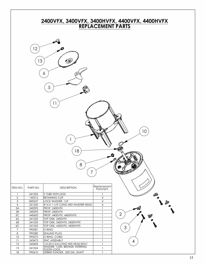
2400VFX, 3400VFX, 3400HVFX, 4400VFX, 4400HVFXREPLACEMENT PARTS
5
6
ITEM NO. PART NO. DESCRIPTION Replacement Parts/QTY.
1 241005 V TUBE WITH LEGS 12 140312 RETAINING CLIP 43 840537 LOCK WASHER, 1/4" 44 251250 #14 X 1-1/4" LONG HEX WASHER HEAD 4
5A 240595 PROP, 2400VFX 15B 340595 PROP, 3400VFX 15C 440600 PROP, 4400VFX, 4400HVFX 16A 241025 TOP DISK, 2400VFX 16B 241035 TOP DISK, 3400VFX, 3400HVFX 16C 241045 TOP DISK, 4400VFX, 4400HVFX 17 990281 O RING 18 990280 SEALING PLUG 1
10 990275 O RING, CORD 111 243475 ZINC ASSEMBLY 112 243405 1/2-20 X 3/4 LONG HEX HEAD BOLT 113 241024 WASHER, 1/2IN, BRONZE, INTERNAL
TOOTH LOCK 118 990410 DEBRIS FLINGER, .500 DIA. SHAFT 1
2400, 3400, 4400 Parts Diagram
16
8400VFX REPLACEMENT PARTS
11
14
9
8
4
10
1
2
3
5
6
7
15
16
ITEM NO.
PART NO. DESCRIPTION 8400
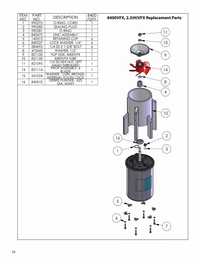
/QTY.1 990275 O RING, CORD 12 990280 SEALING PLUG 13 990281 O RING 14 840475 ZINC ASSEMBLY 15 140312 RETAINING CLIP 66 840537 LOCK WASHER, 1/4" 67 584692 1/4-20 X 1-3/8" BOLT 68 475642 WASHER, 1/2" 19 821100 TOP DISK, 8400VFX 1
10 821120 8400VFX TUBE 111 821095 1/2-20 HEX NUT, LEFT
HAND THREADED 1
14 821114 PROP ASSEMBLY, 6 BLADE 1
15 241024 WASHER, 1/2IN, BRONZE, INTERNAL TOOTH LOCK 1
16 840510 DEBRIS FLINGER, .625 DIA. SHAFT 1
8400VFX, 2.3(H)VFX Replacement Parts
17
5.1VFX REPLACEMENT PARTS
10
12
98
4
11
1
3
2
5
6
7
13
14
ITEM NO. PART NO. DESCRIPTION
5.1VFX PARTS
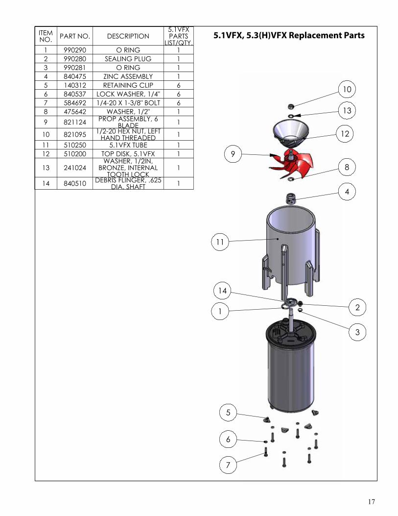
LIST/QTY.1 990290 O RING 12 990280 SEALING PLUG 13 990281 O RING 14 840475 ZINC ASSEMBLY 15 140312 RETAINING CLIP 66 840537 LOCK WASHER, 1/4" 67 584692 1/4-20 X 1-3/8" BOLT 68 475642 WASHER, 1/2" 19 821124 PROP ASSEMBLY, 6
BLADE 1
10 821095 1/2-20 HEX NUT, LEFT HAND THREADED 1
11 510250 5.1VFX TUBE 112 510200 TOP DISK, 5.1VFX 1
13 241024WASHER, 1/2IN,
BRONZE, INTERNAL TOOTH LOCK
1
14 840510 DEBRIS FLINGER, .625 DIA. SHAFT 1
5.1VFX, 5.3(H)VFX Replacement Parts
18
Maintenance Recommendations
** Under No Circumstances should anyone enter the water while a aerator is operating. **** Please keep the original box for maintenance ship-ping. **
The following maintenance procedures can be uti-lized to ensure many years of quality performance from your Kasco aerator and reduce the need for more costly repair work.
PROPER INSTALLATION: Proper installation of Kasco equipment will include a power source with ground fault interruption (GFI). For aerator models, the C-25 control (120V) or C-85 (240/208V) included with the unit have built-in ground fault interrup-tion that is sufficient. Ground fault interrupters are a safety feature that can also alert you to electrical leaks in the equipment. It is extremely important to test the GFI upon installation, each reinstallation, and monthly thereafter to ensure proper operation. If you have repeat, consistent trips on your ground fault, the equipment should be disconnected and removed from the water. The power cord should be inspected for damage and you should call Kasco Marine at 715-262-4488 for further instructions or email Kasco at [email protected].
OBSERVATION: Operating equipment should be observed on a regular basis (daily, if possible) for any reduction or variation in performance. If a change in performance is observed, the equipment should be disconnected from power and inspected for any ma-terial that may have clogged the system or wrapped around the shaft of the motor, especially plastic bags and fishing line. Even though Kasco Aerators and aerators are among the most clog-resistant on the market, it is impossible to protect against all items that can clog equipment and still maintain a flow of water. These materials can be very damaging to the equip-ment under continued operation and must be removed as soon as possible. ALWAYS UNPLUG THE UNIT BEFORE ATTEMPTING TO REMOVE CLOGS.
WINTER STORAGE: In regions where there is sig-nificant freezing in the wintertime, the aerators should be removed from the water to protect them from the expansion pressure of the ice. In many areas, aerators will keep some amount of ice open through the winter.
However, when the water is thrust into the air, it is ex-posed to the colder air temperatures longer and can ac-tually make ice thicker on the pond/lake. Storage over winter is best in a location that is out of the sun and cool, but above 32OF. When storing units during the offseason, it is important to store them upside down if they are going to be sitting for long periods of time. Units that sit upright on a shelf for many months, or even years have a greater likelihood of seals drying out. Storing upside down will ensure oil is lubricating the seals and prevent drying.
CLEANING: Aerators should be removed from the water at least once per year (at the end of the season in cold climates) to clean the exterior of the system, especially the stainless steel motor housing (can). The motor housing is the surface that dissipates heat into the water and any algae, calcium, etc. build-up will be-come an insulator that blocks heat transfer. In warmer regions it is recommended that the motor is removed and cleaned at least two to three times per year de-pending on conditions. In most cases a power washer will be sufficient if the unit and algae are still wet.
SEAL AND OIL REPLACEMENT: This is a sealed motor assembly and seals will wear out over time (similar to brake pads on a car). Replacement of the seals and a change of oil after three years may add longevity to the operation of the motor, saving you the cost of more expensive repairs. In warmer cli-mates where the aerator runs most or all of the year, it is a good idea to replace seals more regularly than you would need to in colder climates where the unit is removed from the water for several months.
ZINC ANODE: A Sacrificial Zinc Anode is supplied on the shaft of all VFX Model aerators for protection of the equipment from corrosion and electrolysis. The zinc anode should be updated (replaced) if reduced to half the original size or if white in color. Corrosion from electrolysis is more commonly associated with saltwater or brackish water, but as a matter of pre-caution, it is important to periodically check the zinc anode in all installations (at least every two to three months).
Seal replacement and all other repair services should be performed by Kasco Marine or a Kasco trained Authorized Repair Center. Any alterations or changes made to Kasco units by an unauthorized source will
19
void the warranty. This includes tampering with the unit, power cord, and/or control box. Please contact Kasco Marine, Inc. at 715-262-4488 for your nearest Authorized Repair Center.
Warranty Policy
Warranty Period:Models: 2400VFX, 3400(H)VFX, 4400(H)VFX - 2 years
Models: 8400VFX, 2.3(H)VFX, 5.1VFX, 5.3(H)VFX - 3 years
Kasco® Marine, Inc. warrants this aerator to be free from defects in material or workmanship (except for the ropes, power cord, and propeller) under normal use and service. The Kasco Marine, Inc. obligation under this warranty is limited to replacing or repairing free of charge any defective part within the warranty period from the date of shipment. Customer shall pay shipping charges for returning the unit to Kasco or an Authorized Repair Center.
THIS WARRANTY IS IN LIEU OF ANY OTHER WARRANTIES, EXPRESSED OR IM-PLIED, AND ANY OTHER OBLIGATION OR LI-ABILITY WHATEVER ON THE PART OF KASCO MARINE, INC. AND IN NO EVENT SHALL KAS-CO MARINE, INC. BE LIABLE FOR ANY SPE-CIAL OR CONSEQUENTIAL DAMAGES.
Warranty is void if:
• The aerator is not maintained properly according to the Maintenance Recommendations supplied in this Owners Manual.
• The aerator is returned for repair without the power cord or if the unit, control box, or power cord are altered in any way from original ship-ment. Cuts in the power cord are not covered under warranty.
• The aerator is damaged by unauthorized tamper-ing.
• The Sacrificial Zinc Anode around the propeller shaft shows significant deterioration. (The Anode must be inspected periodically and replaced if necessary.)
Warranty Claim Procedure:The best method for establishing warranty period is by keeping your original receipt. Also register the aerator online at: www.kascomarine.com
Once the warranty coverage has been established, the unit may be sent to any Kasco Authorized Repair Cen-ter for evaluation and repair. Please call Kasco Marine at 715-262-4488 prior to shipping. Kasco Marine, Inc.800 Deere Rd.Prescott, WI 54021Attn: Repairs
Or call Kasco Marine at 715-262-4488 to locate your nearest Authorized Repair Center. You can also email Kasco at [email protected]
Note: Only complete motor assemblies will be ac-cepted for warranty repair. The power cord and all other components must be returned with the motor as originally assembled. Any missing parts will be replaced at the customer’s expense and, if determined to have caused the failure, could void the entire war-ranty. Some parts are essential for structural support during shipping and others, such as the power cord, are essential to properly diagnose potential causes of failure. It is not necessary to return the control box or float with the motor assembly.
Please include the Repair Form received from Kasco Marine or your local distributor with the shipment. If no Repair Form is available, include your name and physical address for return delivery of the repaired unit and a daytime phone number and/or e-mail ad-dress for correspondence regarding the warranty claim.
Any expedited shipping method for the return of the unit is at the customer’s expense. Kasco Marine will return units repaired under warranty at our expense via ground freight within the continental United States.
Other Repairs:Most failed equipment can be repaired at substantially lower costs than replacement with new. Please ship according to the instructions in the previous section. Again, it is best to call ahead for a Return Authori-
20
zation Number and/or Repair Form so we know the repair is coming.
Kasco Marine does estimates on repairs at the request of the customer. The request for estimate should be included in the letter that accompanies the returned unit and must include a daytime phone number and/or e-mail address. Estimate options are as follows:
We will contact the customer with a total after the unit has been evaluated, but before the work is performed.We will repair the unit only if repair costs are under a stated dollar amount. Example: “Please repair if total is under $150.00 before shipping charges.”
All estimates that are rejected for repair will be de-stroyed unless otherwise directed by the customer. If the customer would like the unit returned, the unit will be restored as closely as possible to the condition in which it was received and shipped at the customer’s expense for shipping and handling charges.
Billing:
All non-warranty repairs will be returned to the cus-tomer prepaid with Visa or Mastercard or shipped C.O.D. with C.O.D. charges unless otherwise directed. Kasco Marine will contact for credit card informa-tion upon completion of the estimate at the customer’s request.
All other warranty and repair inquiries should be di-rected to Kasco Marine, Inc. at 715-262-4488 or [email protected]
Troubleshooting Tips
Below are some helpful troubleshooting tips. If a problem occurs, please double check the assembly and installation instructions as well as the instructions for the proper control panel. More troubleshooting tips can be found at www.kascomarine.com (under the technical tab)
“My Aerator trips the ground fault interrupter in the C-25, C-85, or C-95.” This is the most common symptom of several possible problems. To correctly diagnose the problem, you will need to collect more information. A Ground
Fault Interrupter (GFI) breaker that trips can in- dicate an electrical service problem, water contamina-tion in the unit and/or cord, bad breaker, control box problems, motor problems, etc. Try to find out the answers to these questions before you contact Kasco to narrow down the problem. • How long does it take to trip the breaker? • Does it always take the same amount of time to
trip?• How many times has it tripped?• Has there been any electrical problems in the area
recently?
“My Aerator seems to run slowly.” This can also be a symptom of several possible problems. There could be an electrical problem where the unit is not getting the proper voltage. This could also indicate a problem with the motor of the unit, which needs to be looked at by an Authorized Repair Center. Check that the unit is receiving the proper voltage, and, if so, contact Kasco for further steps.
“My Aerator hums, but will not start. When I spin the prop with a stick, it starts up.” (single phase units only) This indicated a problem with the Starting Capacitor. Each Kasco aerator is equipped with a Starting Capacitor to get the unit going when it is first plugged in. If it is operating, but not spinning and can be started by spinning the prop with a stick, the Start-ing capacitor needs to be replaced by an Authorized Repair Center.
“My Aerator turns itself off and back on without the timer and without tripping the GFI breaker.” (single phase units only) Each Kasco aerator has a Thermal Overload built in that will turn the unit off when it overheats. Once the unit has cooled down, it will start back up. If you are noticing these symptoms, the unit should be unplugged immediately because the Thermal Overload will continue to turn on and off until it burns out and damages the motor. The unit should be unplugged and taken out of the water to find the cause of the problem. The problem could be one of many, such as, low water levels, build-up on the unit to prevent heat dissipation, something inhibiting the free rotation of the shaft, etc. If something is caught in the unit or there is a build-up of algae, calcium or organic matter on the unit, remove the debris and, if caught early enough, the unit should
21
be fine. Contact a Kasco representative before restart-ing the unit.
“My Aerator flow seems to fluctuate and/or be less than usual.” This can occur because of a few different rea-sons. Most of the time, this symptom is caused from unit being clogged with debris. A mat of weeds, many leaves, plastic bags, etc. can clog up the unit and cause it to be starved of water. If the unit does not have the proper amount of water, the flow or pattern will fluc-tuate up and down and look sporadic. If you are see-ing these symptoms, unplug the unit and clean away the debris that is clogging up the screen. Another possibility if these symptoms are noticed, is a chipped or damaged prop that is causing the unit to wobble and not pump properly. When the unit is unplugged, check the prop for damages and replace if damage is found.
“The GFI breaker trips randomly and sporadically. Sometimes it is a few hours of operation, other times it can be days or weeks.” This is referred to as a Nuisance Trip. This usually occurs where the unit is installed a great distance from the initial electric service on the prop-erty where the ground stake is placed. It is caused by either induced current in the ground wire or a base voltage difference due to soil pH levels. To resolve the problem, contact an electrician and install a local grounding stake. This may eliminate the induced cur-rent and any base voltage differences. This problem can also be caused by a bad breaker or receptacle or having unbalanced incoming voltage lines.
22
800 Deere Rd.Prescott, WI 54021Phone: 715-262-4488 - Fax: 715-262-4487www.KascoMarine.com [email protected]
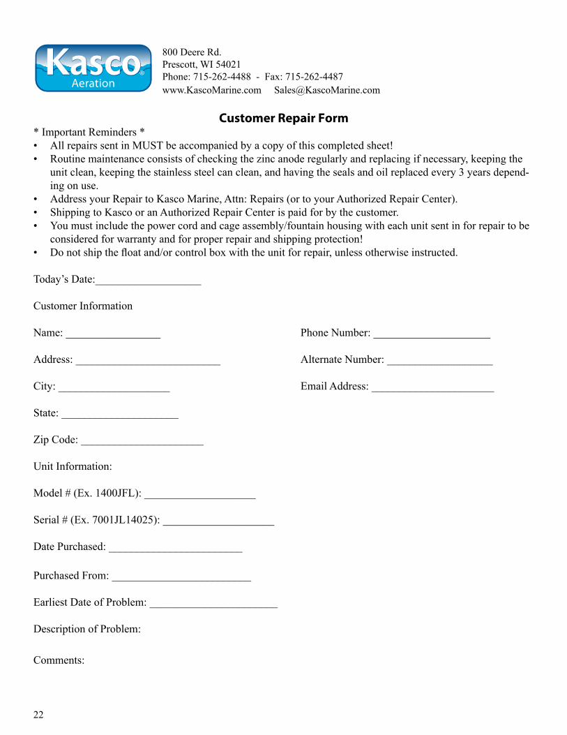
Customer Repair Form* Important Reminders *• All repairs sent in MUST be accompanied by a copy of this completed sheet!• Routine maintenance consists of checking the zinc anode regularly and replacing if necessary, keeping the
unit clean, keeping the stainless steel can clean, and having the seals and oil replaced every 3 years depend-ing on use.
• Address your Repair to Kasco Marine, Attn: Repairs (or to your Authorized Repair Center).• Shipping to Kasco or an Authorized Repair Center is paid for by the customer.• You must include the power cord and cage assembly/fountain housing with each unit sent in for repair to be
considered for warranty and for proper repair and shipping protection!• Do not ship the float and/or control box with the unit for repair, unless otherwise instructed.
Today’s Date:___________________
Customer Information
Name: _________________ Phone Number: _____________________
Address: __________________________ Alternate Number: ___________________
City: ____________________ Email Address: ______________________
State: _____________________
Zip Code: ______________________
Unit Information:
Model # (Ex. 1400JFL): ____________________
Serial # (Ex. 7001JL14025): ____________________
Date Purchased: ________________________
Purchased From: _________________________
Earliest Date of Problem: _______________________
Description of Problem:
Comments:

23

24
Registration Information
Please register your aerator online at: www.kascomarine.comAlso fill in the information below and keep for your records.
Model # (Ex. 5.1VX)_______________________________
Serial # (Ex. 8001VX511725)______________________________
Purchase Date:_____________________
Purchased From:___________________________________
Registration Date: ___________________________
Kasco Marine, Inc.800 Deere Rd.
Prescott, WI 54021
Phone (715) 262-4488 • Fax (715) 262-4487
www.kascomarine.com • [email protected]


![SICregang - Willkommen - Sysmex Austria · Positive Diff. Morph. Count WBC & 27.76 IOA3/uL 1 OA6/uL g/dL] % pgg 1 OA3/uL] fL 113/uL 0/0 0/0 IOA3/uL IOA3/uL 1 OA3/uL IOA3/uL IOA3/uL](https://img.pdfslide.net/doc/110x75/5ac49e847f8b9a2b5c8d1e67/sicregang-willkommen-sysmex-austria-diff-morph-count-wbc-2776-ioa3ul-1-oa6ul.jpg)