Embed Size (px)
Citation preview

LPAdjustableBases.com
owners manualSIMPLICITY
*Queen (shown without mattress)
*Split Cal-King

CONTENTS
Advisory ...................................................................................................................... 3
Acoustics .................................................................................................................... 5
Fabric Cleaning Information .......................................................................................... 5
Installation ................................................................................................................. 6
Remote Control Function ............................................................................................ 14
Remote Control Programming ..................................................................................... 15
Troubleshooting ......................................................................................................... 19
Accessories ............................................................................................................... 20
1-3-25 Warranty ........................................................................................................ 21
CONTENTS
If adjustable base does not operate or if parts are missing, call:
800-888-3078
Do not contact retail store or dealer.
Performance Models Simplicity Owners Manual 99301571-b 3
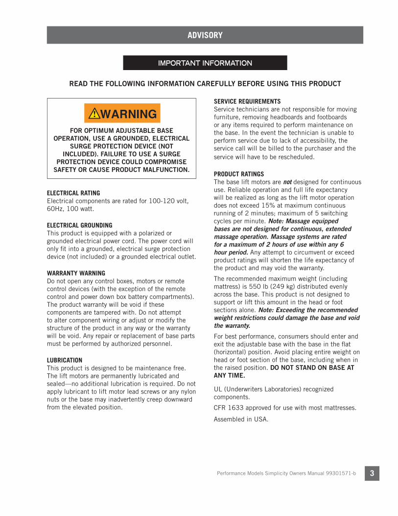
IMPORTANT INFORMATION
READ THE FOLLOWING INFORMATION CAREFULLY BEFORE USING THIS PRODUCT
ELECTRICAL RATING Electrical components are rated for 100-120 volt, 60Hz, 100 watt.
ELECTRICAL GROUNDINGThis product is equipped with a polarized or grounded electrical power cord. The power cord will only fit into a grounded, electrical surge protection device (not included) or a grounded electrical outlet.
WARRANTY WARNINGDo not open any control boxes, motors or remote control devices (with the exception of the remote control and power down box battery compartments). The product warranty will be void if these components are tampered with. Do not attempt to alter component wiring or adjust or modify the structure of the product in any way or the warranty will be void. Any repair or replacement of base parts must be performed by authorized personnel.
LUBRICATIONThis product is designed to be maintenance free. The lift motors are permanently lubricated and sealed—no additional lubrication is required. Do not apply lubricant to lift motor lead screws or any nylon nuts or the base may inadvertently creep downward from the elevated position.
PRODUCT RATINGSThe base lift motors are not designed for continuous use. Reliable operation and full life expectancy will be realized as long as the lift motor operation does not exceed 15% at maximum continuous running of 2 minutes; maximum of 5 switching cycles per minute. Note: Massage equipped bases are not designed for continuous, extended massage operation. Massage systems are rated for a maximum of 2 hours of use within any 6 hour period. Any attempt to circumvent or exceed product ratings will shorten the life expectancy of the product and may void the warranty.
The recommended maximum weight (including mattress) is 550 lb (249 kg) distributed evenly across the base. This product is not designed to support or lift this amount in the head or foot sections alone. Note: Exceeding the recommended weight restrictions could damage the base and void the warranty.
For best performance, consumers should enter and exit the adjustable base with the base in the flat (horizontal) position. Avoid placing entire weight on head or foot section of the base, including when in the raised position. DO NOT STAND ON BASE AT ANY TIME.
UL (Underwriters Laboratories) recognized components.
CFR 1633 approved for use with most mattresses.
Assembled in USA.
ADVISORY
FOR OPTIMUM ADJUSTABLE BASE OPERATION, USE A GROUNDED, ELECTRICAL
SURGE PROTECTION DEVICE (NOT INCLUDED). FAILURE TO USE A SURGE
PROTECTION DEVICE COULD COMPROMISE SAFETY OR CAUSE PRODUCT MALFUNCTION.
WARNINGWARNINGSERVICE REQUIREMENTSService technicians are not responsible for moving furniture, removing headboards and footboards or any items required to perform maintenance on the base. In the event the technician is unable to perform service due to lack of accessibility, the service call will be billed to the purchaser and the service will have to be rescheduled.

Performance Models Simplicity Owners Manual 99301571-b4
ADVISORY
READ THE FOLLOWING INFORMATION CAREFULLY BEFORE USING THIS PRODUCT
IMPORTANT INFORMATION
SMALL CHILDREN / PETS WARNINGAfter the base is unboxed, immediately dispose of packaging material as it can smother small children and pets. To avoid injury, children or pets should not be allowed to play under or on the base. Children should not operate this base without adult supervision.
PACEMAKER WARNINGThis product produces a vibrating sensation. It is possible that individuals with heart-assist pacemakers may experience a sensation similar to exercise. Consult physician for complete information.
HOSPITAL USE DISCLAIMER This base is designed for in-home use only. It is not approved for hospital use and does not comply with hospital standards. Do not use this base with tent type oxygen therapy equipment, or use near explosive gases.
LOCKING CASTER DETAIL
LOCK
LOCKING CASTER SAFETY FEATURE Many adjustable bases are equipped with locking casters to prohibit the base from movement. For best results, place rubber caster cups under locking casters when the base is located on smooth or hard surface flooring—it is possible for locking caster equipped beds to slide without the use of rubber caster cups.
To activate locking casters, push down on the lock tab. To disengage the locking mechanism, push up on the lock tab (see illustration below).
FCC COMPLIANCE The equipment has been tested and found to comply with the limits for a Class B digital device, pursuant to Part 15 of the FCC Rules. These limits are designed to provide reasonable protection against harmful interference when the equipment is operated in a residential environment. This equipment generates, uses, and can radiate radio frequency energy and, if not installed and used in accordance with the instruction manual, may cause harmful interference to radio communications. However, there is no guarantee that interference will not occur in a particular installation. If this equipment does cause harmful interference to radio or television reception, which can be determined by turning the equipment off and on, the user is encouraged to try to correct the interference by one or more of the following measures:
- Reorient or relocate the receiving antenna.
- Increase the separation between the equipment and receiver.
- Connect the equipment into an outlet on a circuit different from that to which the receiver is connected.
- Consult the dealer or an experienced radio/TV technician for help.
This device complies with Part 15 of the FCC rules.Operation is subject to the following conditions: (1)This device may not cause harmful interference,and (2) this device must accept any interferencereceived, including interference that may causeundesired operation.
FCC Caution: Any changes or modifications notexpressly approved by the party responsible forcompliance could void the user’s authority tooperate this equipment.
Radio Frequency = 2.4GHz.

Performance Models Simplicity Owners Manual 99301571-b 5
ACOUSTICS
LIFTING/LOWERING MECHANISMSThe lift/lower feature will emit a minimal humming sound during operation. This is normal.
During operation, the lift arm wheels make contact with the platform support of the base. This applies slight tension on the moving components and resonance is reduced to a minimum level. If excessive noise or vibration is experienced, reverse the movement action (up or down) of the base with the remote control. This should realign the base’s activating mechanisms to the proper operational position.
MASSAGE OPERATIONThe massage feature will emit a minimal tone during operation. This is normal. When the massage level is increased, motor resonance will intensify accordingly.
LOCATION ENVIRONMENTThe level of sound experienced during operation is directly related to the location environment. For example, when a base is located on a hardwood floor with the massage feature in operation, a vibrating tone will be audible. To minimize this resonance, place a piece of carpet, or rubber caster cups, under each leg or caster of the base.
It is possible to experience vibration or noise from the headboard brackets, headboards or footboards if mounting bolts are not firmly tightened.
FABRIC CLEANING INFORMATION
Spot clean only with water based shampoo or foam upholstery cleaner. Pretest a small, inconspicuous area before proceeding. Do not over wet. Do not use solvents to spot clean. Pile fabrics may require brushing with a non-metallic, stiff bristle brush to restore appearance. Hot water extraction or steam cleaning is not a recommended cleaning method.
To prevent overall soiling, frequent vacuuming or light brushing with a non-metallic stiff bristle brush to remove dust and grime is recommended. When cleaning a spill, blot immediately to remove spilled material. Clean spots or stains from the outside to the middle of the affected area to prevent circling. Use a professional furniture cleaning service when an overall soiled condition is apparent.
Performance Models Simplicity Owners Manual 99301571-b6
INSTALLATION
For installation and setup, complete the following procedures, in the order indicated below and on the following pages:
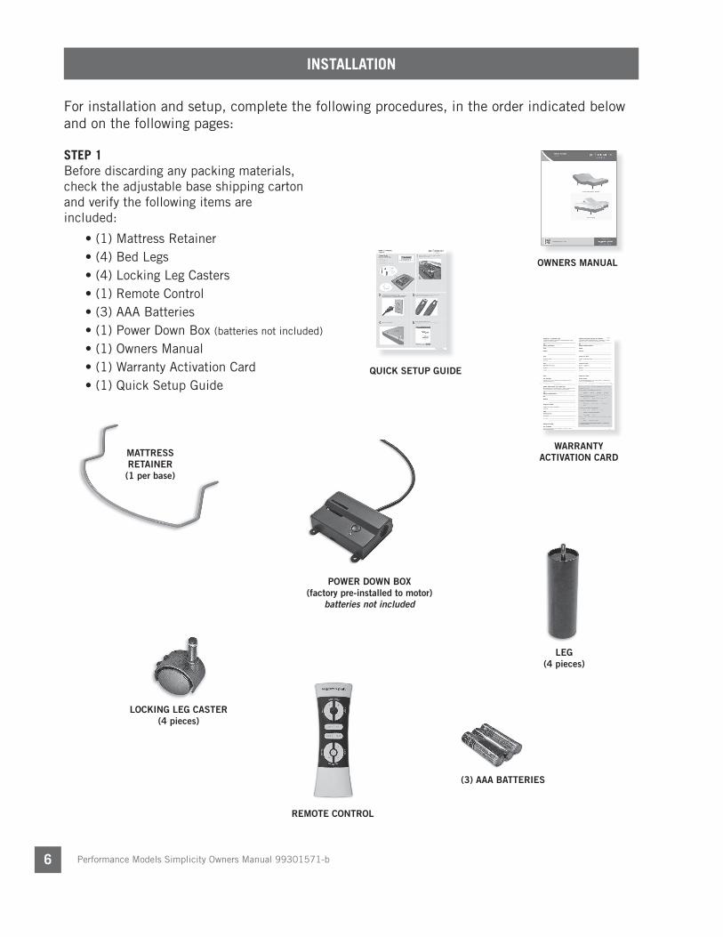
STEP 1 Before discarding any packing materials, check the adjustable base shipping carton and verify the following items are included:
• (1) Mattress Retainer• (4) Bed Legs• (4) Locking Leg Casters
• (1) Remote Control• (3) AAA Batteries• (1) Power Down Box (batteries not included)
• (1) Owners Manual• (1) Warranty Activation Card• (1) Quick Setup Guide
QUICK SETUP GUIDE
LEG(4 pieces)
(3) AAA BATTERIES
LOCKING LEG CASTER(4 pieces)
MATTRESS RETAINER (1 per base)
WARRANTY ACTIVATION CARD
OWNERS MANUAL
REMOTE CONTROL
POWER DOWN BOX(factory pre-installed to motor)
batteries not included

Performance Models Simplicity Owners Manual 99301571-b 7
INSTALLATIONINSTALLATION
STEP 2Remove the hardware box. Cut the zip-tie and remove the mattress retainer.
STEP 3Install (4) legs into the base frame. Simply screw each leg into a tapped hole at the corner of the base frame (FIGURE 1). Insert casters into the bottom of each bed leg.
STEP 5Remove the plastic packaging from the base frame. Carefully rotate the adjustable base over to position the base so it is resting on its legs.
STEP 4 Carefully lift the adjustable base from the shipping carton, keeping the unit top-side-down. Remove and extend out power cord from base.
LEGS – SCREW INTO TAPPED HOLE AT
EACH CORNER
FIGURE 1
AT LEAST TWO PEOPLE ARE RECOMMENDED FOR HANDLING AND
MOVING ADJUSTABLE BASE.
DO NOT ATTEMPT TO SCREW LEGS INTO ANY OTHER INSERTS.
THIS WILL DAMAGE PRODUCT.
CAUTION
POWER CORDS MUST NOT INTERFERE WITH ANY ADJUSTABLE BASE MECHANISMS.
CASTERS – PRESS-FIT INTO BOTTOM OF LEGS (IF APPLICABLE)
WARNINGWARNING
WARNINGWARNING
CAUTIONCAUTION

Performance Models Simplicity Owners Manual 99301571-b8
INSTALLATION
STEP 6 Plug electrical power cord into a working, grounded electrical outlet. Note: An electrical surge protection device is recommended (not included).
STEP 8 Return base to the level position.
STEP 7Install batteries in remote control (3-AAA, included) (FIGURE 2). Note: Make sure batteries are properly oriented. Briefl y activate all functions of the base with the remote control to verify all features are in working order. If base does not operate, refer to the Troubleshooting section of this manual.
BATTERY COMPARTMENT DOOR
PRESS IN ON TAB AND LIFT OUT TO REMOVE BATTERY COMPARTMENT DOOR. INSERT TABS IN TAB SLOTS AND SNAP IN TO REPLACE.
BOTTOM OF REMOTE CONTROL
FIGURE 2
POSITIVE (+) END
TABS
NEGATIVE (-) END

Performance Models Simplicity Owners Manual 99301571-b 9
INSTALLATION
STEP 9 Install mattress retainer at the foot end of the adjustable base as follows:
a. Locate grommeted holes at foot end of base.b. Place mattress retainer ends into grommeted holes in top surface
of adjustable base (FIGURE 3). Press down until horizontal retainer section is fl ush against base.
FIGURE 3
FOOT END OF BASE
MATTRESS RETAINER
NOTE: If base is to be set up without a headboard, install mattress to complete basic installation. If headboard is to be installed, proceed to Headboard Bracket Installation. (Headboard Bracket sold as accessory.)

Performance Models Simplicity Owners Manual 99301571-b10
INSTALLATION
FAILURE TO FOLLOW HEADBOARD BRACKET INSTALLATION INSTRUCTIONS MAY CAUSE HEADBOARD BRACKET INTERFERENCE WITH BASE FOAM DURING BASE OPERATION. BASE FOAM OR BASE COVER DAMAGE COULD RESULT.
3 inches MAX.
FIGURE 4
HEADBOARD BRACKET INSTALLATION (optional accessory)Install headboard brackets to the base frame. When attaching (2) twin size units to a king size headboard an optional swing hinge kit (see accessory section) may be used to connect the twin units.
NOTE
IN ORDER TO AVOID A PERSON OR PET BEING CAUGHT IN THE SPACE REFERENCED
BELOW WHILE THE BED IS IN MOTION, THE BOTTOM OF THE HEADBOARD CROSS MEMBER MUST BE POSITIONED SO THAT
THERE IS NO MORE THAN 3 INCHES (76.2MM) BETWEEN THE HEADBOARD AND THE TOP OF THE MATTRESS (FIGURE 4). DO NOT EXCEED 3 INCHES (76.2MM). FAILURE
TO FOLLOW THIS INSTRUCTION COULD RESULT IN SERIOUS PERSONAL INJURY OR
DEATH.
Headboard cross member location must not exceed 3 inches (76.2mm) from the top of the mattress.
WARNINGWARNING

Performance Models Simplicity Owners Manual 99301571-b 11
INSTALLATION
STEP 10 Install headboard brackets to the base frame as follows:
a. Raise the head section of the base (with remote control) to gain access to the base frame.
b. Locate channel connector kit (FIGURE 5). On one side of base frame, locate (2) holes for channel connector mounting (FIGURE 6).
c. Position channel connector so that the fl at side is fl ush against base frame. Attach channel connector to base frame using (2) 1½ inch long hex head bolts/nuts (FIGURE 6). Tighten bolts. Note: For units with 74” base length, use inner mounting holes. For units with 80” base length, use outer mounting holes (FIGURES 5 and 6).
80” BASE LENGTH MOUNTING HOLES
74” BASE LENGTH MOUNTING HOLES
FIGURE 5
(2) 1-1/2 INCH LONG HEX HEAD BOLTS/NUTS
74” BASE LENGTH MOUNTING HOLES
FIGURE 6

Performance Models Simplicity Owners Manual 99301571-b12
d. Using (2) 3 inch long carriage bolts/nuts, attach (1) headboard bracket channel to (1) channel connector (FIGURE 7). Hand tighten bolts/nuts (loosely) to allow adjustment of the headboard bracket channels.
FIGURE 7
FIGURE 8
USE (2) 3 INCH LONG CARRIAGE BOLTS TO ATTACH HEADBOARD BRACKET CHANNEL TO BASE FRAME
HEADBOARD BRACKET CHANNEL (queen size shown)
HEADBOARD BRACKET FLANGE
e. Attach (1) headboard bracket fl ange to one of the bracket channels with (2) 1 inch long hex head bolts/nuts (FIGURE 8). Tighten bolts.
f. Repeat procedure to attach the other headboard bracket.
SLIDE BRACKET ASSEMBLIES IN OR OUT TO ACHIEVE
POSITION
ADJUST AS REQUIRED TO
ACHIEVE POSITION
USE (2) 1 INCH LONG HEX HEAD BOLTS TO ATTACH HEADBOARD BRACKET FLANGE TO BRACKET CHANNEL
INSTALLATION

Performance Models Simplicity Owners Manual 99301571-b 13
g. When installing a headboard, footboard, or four-piece surround (case good), allow for 1.5 inches (38.1mm) to 2 inches (50.8mm) of clearance at the head and foot of the bed and a minimum of ½ inch to ¾ inch on the sides.
h. Firmly tighten the 3 inch carriage bolts of both headboard bracket channels.
i. Measure the distance (center-to-center) between the mounting holes in the headboard.
j. Measure the center-to-center distance between the mounting slots of the headboard bracket flanges.
k. If bracket flange adjustment is required to accept the headboard, remove the 1 inch headboard bracket flange bolts and move flanges side-to-side for the adjustment. Reinstall bolts and tighten.
l. Install headboard.
INSTALLATION
Typical Simplicity adjustable base installation is now complete.
STEP 11 Install mattress on adjustable base.
Performance Models Simplicity Owners Manual 99301571-b14
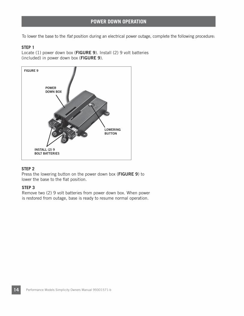
POWER DOWN OPERATION
To lower the base to the fl at position during an electrical power outage, complete the following procedure:
STEP 1 Locate (1) power down box (FIGURE 9). Install (2) 9 volt batteries (included) in power down box (FIGURE 9).
STEP 2 Press the lowering button on the power down box (FIGURE 9) to lower the base to the fl at position.
FIGURE 9
POWER DOWN BOX
LOWERING BUTTON
INSTALL (2) 9 BOLT BATTERIES
STEP 3 Remove two (2) 9 volt batteries from power down box. When power is restored from outage, base is ready to resume normal operation.

Performance Models Simplicity Owners Manual 99301571-b 15
REMOTE CONTROL FUNCTION
REMOTE CONTROL REQUIRES THREE (3) AAA SIZE BATTERIES (INCLUDED). THE BUTTONS ON THE REMOTE CONTROL ILLUMINATE FOR 2.5 SECONDS WHEN PRESSED AND RELEASED.
NOTE
MASSAGE SETTINGS CANNOT BE SAVED IN PRESET CUST 1 AND CUST 2 BUTTONS.
NOTE
HEAD DOWN BUTTONPress and hold to lower the head section.
CUST 1 BUTTONPress and hold to adjust base to the
programmed position.
*To program a position, adjust base to desired position, press and hold the set
button until the massage motors turn on and off, then press and hold the Cust 1
button until the massage motors turn on and off.
SET BUTTONPress and hold to program Cust 1 and Cust 2 presets.
CUST 2 BUTTONPress and hold to adjust base to the
programmed position.
*To program a position, adjust base to desired position, press and hold the set
button until the massage motors turn on and off, then press and hold the Cust 2
button until the massage motors turn on and off.
HEAD MASSAGE UP BUTTONPress to increase massage intensity.
Massage has 3 speeds: Low, medium and high. Massage will automatically
shut off after 15 minutes.
FOOT MASSAGE UP BUTTONPress to increase massage intensity. Massage has 3 speeds: Low, medium, and high. Massage will automatically shut off after 15 minutes.
HEAD MASSAGE DOWN BUTTONPress to decrease massage intensity.
Massage has 3 speeds: Low, medium and high. Massage will automatically
shut off after 15 minutes.
FOOT MASSAGE DOWN BUTTONPress to decrease massage intensity. Massage has 3 speeds: Low, medium, and high. Massage will automatically shut off after 15 minutes.
MASSAGE ON/OFF BUTTONPress to turn both massage motors on or off.
FOOT DOWN BUTTONPress and hold to lower the foot section.
FLAT BUTTONPress and hold to lower the base to the level position.
HEAD UP BUTTONPress and hold to raise the head section.
FOOT UP BUTTONPress and hold to raise the foot section.
PRESS & HOLD TO ONE TOUCH
Note: If using 2 remotes to operate 1 or more bases, both remotes must be set to the same “press & hold” or “press & touch” mode.To change remote control functions from “press and hold” to “one touch”, simultaneously press the HEAD MASSAGE DOWN and FOOT MASSAGE DOWN buttons. The massage motor will turn on and off confi rming the change. Your base is now set to “one touch.”When in “one touch” mode:Cust 1 and Cust 2 buttonsOne touch button. Base will adjust to the programmed position. Press any other button to stop the base during movement.Flat buttonOne touch button. Base will shut off massage motor, if active, and adjust base to level position. Press any other button to stop the base during movement.To revert back to factory settings, simultaneously press and hold the SET button and the FLAT button. The massage motor will turn on and off confi rming the change. Your base is now set to factory settings. Note: Cust 1 and Cust 2 positions willrevert to factory preprogrammed positions.
Performance Models Simplicity Owners Manual 99301571-b16
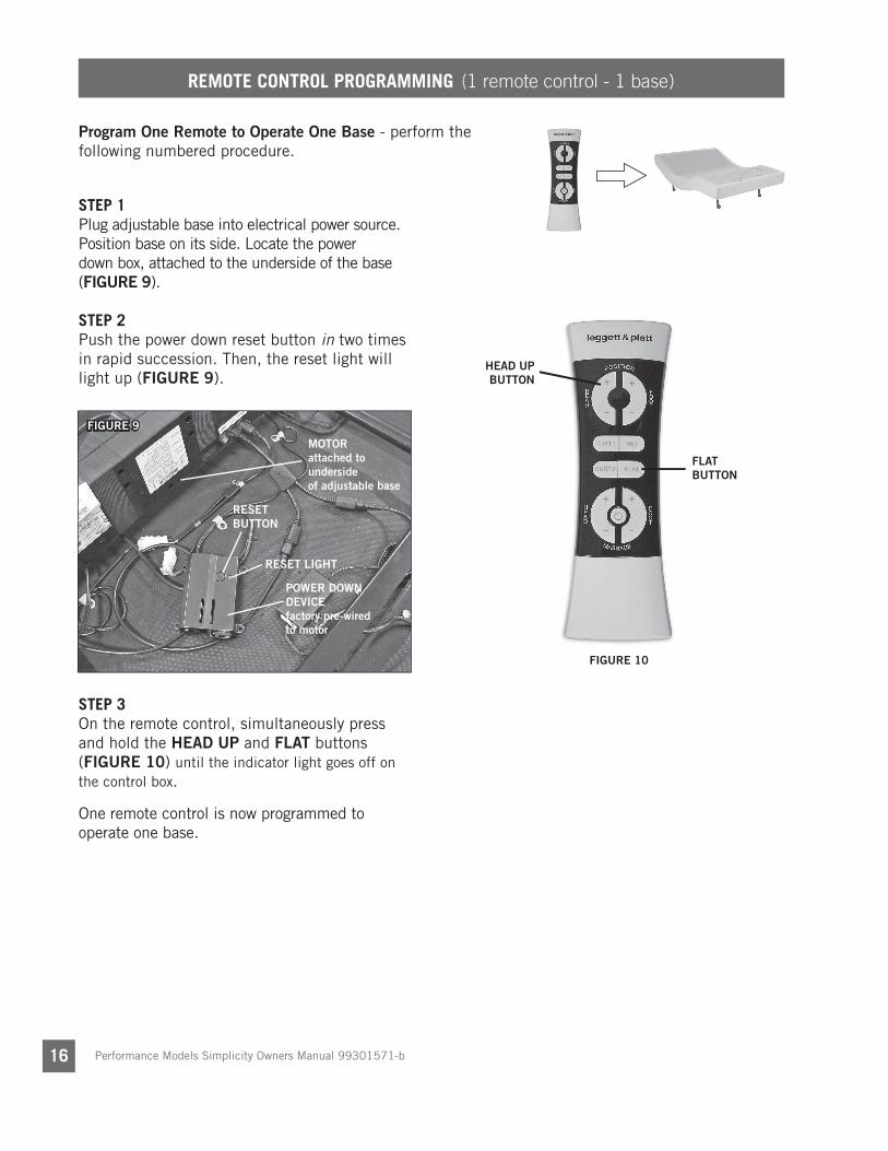
REMOTE CONTROL PROGRAMMING (1 remote control - 1 base)
STEP 1Plug adjustable base into electrical power source. Position base on its side. Locate the power down box, attached to the underside of the base (FIGURE 9).
STEP 2Push the power down reset button in two times in rapid succession. Then, the reset light will light up (FIGURE 9).
STEP 3On the remote control, simultaneously press and hold the HEAD UP and FLAT buttons (FIGURE 10) until the indicator light goes off on the control box.
One remote control is now programmed to operate one base.
Program One Remote to Operate One Base - perform the following numbered procedure.
FIGURE 10
HEAD UP BUTTON
FLAT BUTTON
FIGURE 9
RESET BUTTON
RESET LIGHT
MOTORattached to undersideof adjustable base
POWER DOWN DEVICEfactory pre-wired to motor

Performance Models Simplicity Owners Manual 99301571-b 17
REMOTE CONTROL PROGRAMMING (1 or 2 remote controls - 2 bases)
BASE 1
BASE 2
Program One or Two Remotes to Operate Two Bases- perform the following numbered procedure. Note: Make sure both remotes are in “press & hold” mode and both bases are fl at before beginning procedure. IF USING 2 REMOTES TO OPERATE 1 OR MORE BASES, BOTH REMOTES MUST BE IN THE SAME “PRESS & HOLD” OR “PRESS & RELEASE” MODE FOR FLAT OR PROGRAMMABLE BUTTONS TO FUNCTION.
STEP 1Plug both adjustable bases into electrical power source. Operate both remote controls to verify each remote functions properly with its respective base. NOTE: See 1-to-1 programming procedure if bases do not operate. Using remote controls, adjust both bases to fl at position. Unplug both bases from electrical power source.
STEP 2Choose base 1 remote. Retain base 2 remote control as a spare or use if 2 remotes are desired to operate both bases.
STEP 3Position both bases on their sides, in close proximity to each other. CAUTION: AT LEAST TWO PEOPLE ARE RECOMMENDED FOR HANDLING AND MOVING ADJUSTABLE BASE.
STEP 4Locate control box on both bases and unplug both power down devices from MFP port.
STEP 5Locate dual sync cable (FIGURE 11). Insert one power down cord male plug into one female plug of dual sync cable.
STEP 6Insert one male plug of dual sync cable into the MFP port of control box of base 1 (FIGURE 12).
STEP 7Insert the other power down cord male plug into the other female plug of dual sync cable. Insert the other male plug of dual sync cable into the MFP port of control box of base 2 (FIGURE 13).
STEP 8Turn both bases over so they are resting on their legs. CAUTION: MAKE SURE CABLE IS CLEAR OF BASE AND FREE OF ANY PINCH POINTS.
OR
REMOTE 1 REMOTE 2
STEP 9Plug both bases into electrical power source. Operate both bases with either one or both remote controls. NOTE: If bases do not operate in unison with either of the remotes, verify dual sync cable connections are fully seated at both control boxes.
FIGURE 12
CONTROL BOX 1attached to undersideof adjustable base 1
MFPPORT
MASSAGEPORT
RESETPORT
remove power down device and insert male plug here
FIGURE 11
DUAL SYNC CABLE
MALE PLUGS
FEMALE PLUG
FEMALE PLUG
FIGURE 13
CONTROL BOX 2attached to undersideof adjustable base 2
remove power down device and insert male plug here
MFPPORT
MASSAGEPORT
RESETPORT

Performance Models Simplicity Owners Manual 99301571-b18
“PRESS & HOLD” TO “ONE TOUCH” PROGRAMMING (1 or 2 remote controls - 2 bases)
TO CHANGE FROM “PRESS & HOLD” TO “ONE TOUCH” PROGRAMMINGSTEP 1Adjust base to the flat position.
STEP 2Simultaneously press the HEAD MASSAGE DOWN and FOOT MASSAGE DOWN buttons on either of the remote controls. The massage motors will turn on and off confirming the change.
WHEN IN “ONE TOUCH” MODE:
Cust 1 and Cust 2 buttonsOne touch button. Base will adjust to the programmed position. Press any other button to stop the base during movement.
Flat buttonOne touch button. Base will shut off massage motor, if active, and adjust base to level position. Press any other button to stop the base during movement.
REVERT BACK TO FACTORY SETTINGSTo revert back to factory settings, simultaneously press and hold the SET button and the FLAT button on either of the remote controls.. The massage motor will turn on and off confirming the change. Your base is now set to factory settings.
WHEN OPERATING 2 REMOTE CONTROLS, MAKE SURE BOTH REMOTES ARE IN “PRESS & HOLD” MODE AND BOTH BASES ARE FLAT BEFORE BEGINNING PROCEDURE.
NOTE: IF USING 2 REMOTES TO OPERATE 1 OR MORE BASES, BOTH REMOTES MUST BE SET TO THE SAME “PRESS & HOLD” OR “PRESS & TOUCH” MODE.
NOTE

Performance Models Simplicity Owners Manual 99301571-b 19
REMOTE CONTROL PROGRAMMING (separating 2 bases)
REMOTE CONTROL 1
BASE 1
BASE 2REMOTE CONTROL 2
Separate Two Bases - for independent adjustable base movement, perform the following numbered procedure.
STEP 1Unplug both bases from electrical power outlet. Position both bases on their sides, in close proximity to each other. CAUTION: AT LEAST TWO PEOPLE ARE RECOMMENDED FOR HANDLING AND MOVING ADJUSTABLE BASE.
STEP 3Remove the male plug of dual sync cable from the MFP port of control box of both bases (FIGURE 14). Plug power down devices into the MFP port of the control boxes of both bases.
STEP 2Locate control box on both bases. Locate dual sync cable plugged into the MFP port of both bases.
STEP 4Plug base 1 into electrical power outlet. On the power down box for base 1, push the reset button in two times in rapid succession. Then, the reset light will light up (FIGURE 15).
STEP 5On remote control 1, simultaneously press and hold the head up and fl at buttons (FIGURE 16) until the reset light goes off on the power down box.
STEP 6Repeat Steps 4 & 5 with base 2 and remote control 2.
STEP 7Turn both bases over so they are resting on their legs. CAUTION: AT LEAST TWO PEOPLE ARE RECOMMENDED FOR HANDLING AND MOVING ADJUSTABLE BASE.
Independent remote control operation is nowrestored (remote control 1 operating base 1; remotecontrol 2 operating base 2).
HEAD UP BUTTON
FLAT BUTTON
FIGURE 16
FIGURE 14
CONTROL BOX attached to undersideof both adjustable bases
remove the male plug from both control boxesand plug in power down devices
FIGURE 15
RESET BUTTON
RESET LIGHT
MOTORattached to undersideof adjustable base
POWER DOWN DEVICEfactory pre-wired to motor
MFPPORT
MASSAGEPORT
RESETPORT

Performance Models Simplicity Owners Manual 99301571-b20
TROUBLESHOOTING
If the adjustable base fails to operate, investigate the symptoms and possible solutions provided in the chart below:
SYMPTOM SOLUTION• Verify power cord is plugged into a working, grounded
electrical outlet. A grounded, electrical surge protection device is recommended. Test outlet by plugging in another working appliance.
• If the base was operated over the rated duty cycle, thermal switch opens. Wait 30 minutes before trying to operate the base. Once the base resumes normal operation, do not exceed the duty cycle.
• Program the remote control (see Remote Control Programming section of this manual for programming procedures).
• Unplug power cord, wait 30 seconds and plug in to reset electronic components.
• Electrical circuit breaker may be tripped. Check electrical service breaker box to verify.
• Defective surge protection device or electrical outlet. Test outlet by plugging in another working appliance.
• Replace batteries in the remote control.
• Base mechanism may be obstructed. Elevate base and check for obstruction. Remove obstruction.
• Head section may be too close to the wall.
• Headboard may be too close the edge of the mattress. Verify a 1.5” (38.1mm) to 2” (50.8mm) distance between headboard brackets and mattress. Adjust if required.
• Verify headboard brackets were removed during installation. Remove headboard brackets if still attached to the underneath side of base.
• If base is located on hard surface flooring, place carpet pieces or rubber caster cups under each leg or caster of the base. (See accessory page for rubber caster cup order information.)
• Elevate the head or foot section a short distance (with the remote control) to realign the lift/lower mechanisms with the bed support platform.
• Verify that the base is not positioned against a wall, nightstand, or other object that may cause vibration or noise.
• If base is installed over a bed frame, verify massage motors are not causing bed frame (or bed frame components) to vibrate.
• Verify that headboard attachment hardware is tightened firmly (if used).
Remote control illuminates and appears to be operable, but will not activate base.
No features of the base will activate.
Remote control will not illuminate.
Head or foot section will elevate, but will not return to the horizontal (flat) position.
Excessive massage motor noise.

Performance Models Simplicity Owners Manual 99301571-b 21
ACCESSORIES
OPTIONAL EQUIPMENTContact customer service toll free (800-888-3078) to order the accessories indicated in the chart below.
4B6117
4B6118
4B1806
4B7410
4B1034
4B1833
4B2100
4B2101
Head Board Brackets-TXL
Head Board Brackets-FXL/Q
Push-in Locking Casters (set of 4)
Bed Link Kit (connects two bases together)
Rubber Caster Cups (set of 4)
4” Legs (set of 4)
5” Legs (set fo 4)
7” Legs (set of 4)
ACCESSORY DESCRIPTION CODE IMAGE

Performance Models Simplicity Owners Manual 99301571-b22
1 YEAR, 3 YEAR AND 25 YEAR LIMITED WARRANTY
In this warranty: “Adjustable base” means the adjustable bed foundation sold by L&P to the dealer. The “adjustable base” does not include the mattress. “L&P” means Leggett & Platt, Incorporated. “Purchaser” and “You” both mean the consumer who is the original purchaser of this adjustable base made by L&P. This warranty is not transferrable. “Warranty Commencement Date” means either (i) the date You purchased a new and unused L&P adjustable base or (ii) the date of manufacture of this adjustable base if You purchased an L&P adjustable base that has been used as floor or display model. L&P warrants this adjustable base to You on the terms and over the reducing periods of time set out below. All warranty claims require notice from You to be given to L&P in the manner set out below, and to be received by L&P inside the applicable warranty time period. 1ST YEAR FULL WARRANTYFor the first year from the Warranty Commencement Date, your adjustable base is warranted against non-excluded defects in L&P’s workmanship or materials. During the first year from the Warranty Commencement Date, L&P will repair or replace (at no cost to You) any defective adjustable base part, and L&P will pay all authorized labor and transportation costs associated with the repair or replacement of any parts found to be defective.
2ND & 3RD YEAR LIMITED WARRANTYDuring the second and third year from the Warranty Commencement Date, L&P will replace any adjustable base part found to be defective and not excluded by this warranty. You are responsible to pay all service and transportation costs related to the costs of receiving and installation of the new part.
4TH YEAR TO END OF 25TH YEAR LIMITED WARRANTYStarting in the fourth year from the Warranty Commencement Date and through to the end of the 25th year from the Warranty Commencement Date, L&P will replace steel and mechanical base parts found to be defective and not excluded by this warranty. This warranty does not cover any electronics, electrical components, drive motors or massage motors. You are responsible to pay all service and transportation costs related to receiving and installation of the new part and a portion of the cost of the replacement steel and mechanical part, based on the number of months that the base has been owned by you since the fourth anniversary of the Warranty Commencement Date. By the end of the 25th year, no portion of the replacement cost is covered by L&P. You will be required to pay 1/22nd of the then current replacement cost of the part multiplied by the number of years past the third year from the Warranty Commencement Date. This portion is calculated using the following formula: Cost of the part divided by 22 [being the number of years in years 4 to 25 inclusive], multiplied by the number of years you have owned the base since the end of the first 3 years. For example, if you make a claim for a part eligible for this warranty in the 5th year since the Warranty Commencement Date, you would be responsible for paying: $100 part cost divided by 22, multiplied by 2 = $9.09.
ADDITIONAL TERMS AND CONDITIONSThis warranty requires notice to be given to L&P of any claim for repairs or replacement parts.
EXCLUSIONS:This warranty does not apply; (a) to any damage caused by You; (b) if there has been any repair or replacement of adjustable base parts by an unauthorized person; (c) if the adjustable base has been mishandled (whether in transit or by other means), subjected to physical or electrical abuse or misuse, or otherwise operated in any manner inconsistent with the operation and maintenance procedures outlined in the Owner’s Manual and this warranty; (d) to damage to mattresses, fabric, cables, electrical cords or items supplied by dealers (contact the dealer for warranty information on these items); (e) if there has been any modification of the adjustable base without prior written consent by L&P; or (f) to costs for unnecessary service calls, including costs for in-home service calls solely for the purpose of educating You about the adjustable base or finding a satisfactory power connection.
This warranty will be void if either the recommended weight restriction is not followed (refer to the advisory section of the Owner’s Manual) or if You sell or give or transfer the base to another person.
Any repairs to or replacement to Your adjustable base or its components under the terms of this limited warranty does not extend the applicable warranty from the Warranty Commencement Date. This time limitation may not apply in some jurisdictions, including the Province of Quebec.
The decision to repair or to replace defective parts under this warranty shall be made, or cause to be made, by L&P at its option and in its sole discretion.
Continued on next page...

Performance Models Simplicity Owners Manual 99301571-b 23
1 YEAR, 3 YEAR AND 25 YEAR LIMITED WARRANTY
Repair or replacement shall be the sole remedy of the Purchaser. There shall be no liability on the part of L&P for any special, indirect, incidental, or consequential damages or for any other damage, claim, or loss not expressly covered by the terms of this warranty.
This limited warranty does not include reimbursement for inconvenience, removal, installation, setup time, loss of use, shipping, or any other costs or expenses. L&P and its service technicians will not be responsible for moving furniture or any other items not attached to the adjustable base in order to perform service on the adjustable base.
It is the sole responsibility of You to provide adequate space and accessibility to the adjustable base. In the event that the technician is unable to perform service due to lack of accessibility, the service call will be billed to You and the service will have to be rescheduled.
L&P makes no other warranty whatever, express or implied, and all implied warranties of merchantability and fitness for a particular purpose are disclaimed by L&P and excluded from this agreement.
Some American States do not allow the exclusion or limitation of incidental or consequential damages, so the above limitation or exclusion may not apply to You.
This warranty gives You specific legal rights, and You may also have other rights, which may vary from jurisdiction to jurisdiction. This warranty is valid in all 50 American States, the District of Columbia, Puerto Rico, and all 10 Provinces and 3 Territories of Canada.
For customer service under this limited warranty, give notice to L&P by mail, phone, email or online to the addresses set out below:
Leggett & Platt, IncorporatedPO Box 668
Lexington, North Carolina 27293
toll free phone: 1.800.888.3078online: lpadjustablebases.com
email: [email protected]
PLEASE DO NOT CONTACT YOUR RETAIL DEALER OR ANY OTHER SERVICE PERSONNEL

99301571-b EDR13563 6/16
NATIONWIDE CUSTOMER SERVICE toll free: (800) 888-3078© 2016 Leggett & Platt Adjustable Bed Group, a division of Leggett & Platt Incorporated