Embed Size (px)
Citation preview

OWNER’S MANUALIMPORTANT INFORMATION FOR THE INSTALLER AND THE OWNER
INCLUDED: THERMOMASSEUR® INSTALLATION USING THE MIA® SERIES CONTROLS
IMP
OR
TAN
T: T
O B
E K
EP
T F
OR
TH
E O
WN
ER
+ Register your warranty online www.bainultra.com/warranty


OWNER’S MANUAL
3 www.bainultra.com
Printed in Canada. Copyright © May 2017 BainUltra Inc. All rights reserved. 45220001Some products, specifications, and services mentioned in this manual are described in pending patent applications or are protected by patents.
TABLE OF CONTENTS
SAFETY INSTRUCTIONS 4
THERMOMASSEUR®
PARTS AND TOOLS 5
SITE PREPARATION 6
THERMOMASSEUR® INSTALLATION 7 - 9
PLUMBING INSTALLATION 10 - 12
BALNEO®, AMMA® AND ORIGAMI FREESTANDING
PARTS AND TOOLS 13
SITE PREPARATION 14 - 15
INSTALLATION 16 - 19
TURBINE
TECHNICAL SPECIFICATIONS 20
ELECTRICAL INSTALLATION 21 - 23
REMOTE MOUNTING 24 - 25
SKIRTS
GENERAL INSTRUCTIONS 26
PARTS AND TOOLS 27
INSTALLATION 28 - 40
THE MIA® SERIES CONTROLS
INSTALLATION 41
USER GUIDE 42 - 52
MAINTENANCE 53 - 54
TROUBLESHOOTING 55 - 56
WARRANTY 57
DRILLING TEMPLATES 59 - 61
956, chemin OlivierLévis (Québec)G7A 2N1
T 418.831.7701 1.800.463.2187
F 418.831.6623 1.800.382.8587 [email protected]

4
OWNER’S MANUAL | SAFETY INSTRUCTIONS
1 800 463.2187 From 8 a.m. to 8 p.m. Monday to Thursday (EST) . From 8 a.m. to 5 p.m. on Friday (EST)
Printed in Canada. Copyright © May 2017 BainUltra Inc. All rights reserved. 45220001Some products, specifications, and services mentioned in this manual are described in pending patent applications or are protected by patents.
READ AND FOLLOW ALL INSTRUCTIONS • SAVE THESE INSTRUCTIONS
WARNINGS• Risk of hyperthermia; people using medication and/or having an adverse medical history should consult a physician
before using a Hydro-thermo massage® bathtub equipped with a heater.• Risk of hyperthermia and possible drowning: do not use a Hydro-thermo massage® bathtub equipped with heater
immediately following strenuous exercise. • Risk of fetal injury; pregnant or possibly pregnant women should consult a physician before using a Hydro-thermo
massage® bathtub equipped with a heater. • Risk of accidental injury or drowning; do not use drugs or alcohol before or during the use of a Hydro-thermo massage® bathtub
equipped with a heater. • Use this unit only for its intended purposes or as described in this manual. Use only accessories or devices recommended
by the manufacturer. • Risk of hyperthermia and possible drowning. Check and adjust water temperature before use. Water temperature
exceeding 100ºF (38ºC) may be injurious to your health. • To reduce the risk of injury, as with any other conventional bath, do not allow children or physically impaired people
to use this unit unless they are closely supervised at all times.• To avoid injury, exercise care when entering or exiting the Thermomasseur®.• The Geysair should always be connected to the hot water intake. If it is not the case, then, the Geysair should be deactivated via
the bath control.
RISK OF ELECTRICAL SHOCK• Disconnect electric power before servicing.• Do not permit electrical appliances (hair dryer, lamp, telephone, radio, television, etc.) within 5’ (1,5 m) of the Thermomasseur®.• Before using the Thermomasseur®, its exterior construction (podium or skirting) should be finished so that a bather cannot ac-
cidentally come in contact with electrical components (turbine and power module). • For indoor use only.
ELECTRICAL CONNECTIONS:• Never drop or insert objects into any openings.• The Thermomasseur® must be connected only to a supply circuit that is protected by a 20 amp class A ground fault circuit
interrupter (GFCI). Optional therapies such as Chromotherapy and/or 2nd heated backrest and/or WarmTouchShell® must be connected to a supply circuit that is protected by a 15 amp class A ground fault circuit interrupter (GFCI). This interrupter is supplied by a certified electrician and must be tested on a regular basis in accordance with manufacturer’s instructions. The GFCI ground must be connected. If defective, do not use the Thermomasseur. Disconnect immediately and call a certified electrician.
• Use 12 AWG (or greater) copper conductors that resist temperatures of at least 194ºF (90ºC).• Canada only: for permanently connected units. A green-colored terminal (or a wire connector marked g., gr., ground
or grounding) is provided within the terminal compartment (not applicable if unit supplied with an electric plug). To reduce the risk of electrocution, connect this terminal or connector to the grounding terminal of your electric service or supply panel with conductor equivalent in size to the circuit conductors supplying the equipment and be 12 AWG or more.
• All electrical connections must be carried out by a certified electrician and must respect federal, provincial/state, and local building codes and regulations.
• Install in accordance with manufacturer’s installation instructions.• For ThermoMasseur baths using remote turbine installation (not mounted on the bath), grounding
continuity must be tested
between the bath grounding terminal and the bath power supply. Failure to perform the grounding continuity test could result in serious personal injury.
WATER LEAK TEST • Once plumbing is fully installed and before beginning any other work, fill the ThermoMasseur® with water to overflow level and
wait 30 minutes. Check all plumbing hook-ups and bath for leaks. BainUltra® is not responsible for any water damage caused by improper installation (see Warranty section).
IMPORTANT SAFETY INSTRUCTIONS PERTAINING TO RISKS OF FIRE, ELECTROCUTION OR PERSONAL INJURY

THERMOMASSEUR® | OWNER’S MANUAL
5 www.bainultra.com
Printed in Canada. Copyright © May 2017 BainUltra Inc. All rights reserved. 45220001Some products, specifications, and services mentioned in this manual are described in pending patent applications or are protected by patents.
TH
ER
MO
MA
SSE
UR
®
5
TH
ER
MO
MA
SSE
UR
®
IMPORTANT • Before starting installation, ensure that parts received match your order. For all questions, call BainUltra® at 1 800 463-2187.
A-10 Drill
A-11 11/64” drill bit
A-12 82° routing bit
A-13 Screws
A-14 Appropriate screwdriver
A. PARTS AND TOOLS
TILE FLANGE INSTALLATION
MOLDED TILE FLANGE INSTALLATION
A-1 24” Level
A-2 24” Square
A-3 Caulking gun
A-4 Pencil
A-5 Hole saw
A-6 1/16” drill bit
SKIRT INSTALLATION
OTHER NECESSARY ITEMS
See skirt section.
• Wood shims
• Silicone
A-3
A-2
A-1
A-4 A-5
A-10 A-11 A-12 A-13
A-7 A-8
A-9
A-14
A-6
A-7 Miter box (angle cutter)
A-8 Fine tooth saw
A-9 Double-face tape
THERMOMASSEUR® - PARTS AND TOOLS
THERMOMASSEUR®
PARTS AND TOOL

6
OWNER’S MANUAL | THERMOMASSEUR®
1 800 463.2187 From 8 a.m. to 8 p.m. Monday to Thursday (EST) . From 8 a.m. to 5 p.m. on Friday (EST)
Printed in Canada. Copyright © May 2017 BainUltra Inc. All rights reserved. 45220001Some products, specifications, and services mentioned in this manual are described in pending patent applications or are protected by patents.
TH
ER
MO
MA
SSE
UR
® THERMOMASSEUR®
SITE PREPARATION
There is a technical specification sheet for each BainUltra® ThermoMasseur® which includes information such as necessary dimensions of site before installation. If you do not already have the technical specifications, download from the BainUltra® site at: www.bainultra.com or call us at: 1 800 463-2187.
• See faucet manufacturer’s technical specifications for zoning and plan water supply accordingly.
• Position drain according to manufacturer’s specifications.
FAUCET INSTALLATION
Before installing, ensure that the floor underneath the bath can support 1,500 lbs (680 kg). The bath may sit directly on the floor. However, the bath may also be installed on a bed of concrete. For this type of installation, it is recommended that you insulate the concrete between two sheets of plastic, one on floor and the other underneath bath.
• A service access is necessary. Minimum dimensions are: 22” x 18” (55 cm x 46 cm) to properly reach all electrical components of the system.
• An air vent is also necessary. Minimum dimensions are: 2” x 4” (5 cm x 10 cm) to ensure proper functioning of the turbine. The service access panel is often the best place to install the air vent.
All ThermoMasseur® components are factory-installed. If for practical or accessibility reasons, the turbine and the InMix (Chromatherapy) module must be moved, follow recommendations outlined in TURBINE - REMOTE MOUNTING section of this manual.
BEDDING
SERVICE ACCESS AND VENTILATION
REMOTE MOUNTING
• The space surrounding the turbine air intake must be large enough and free of debris for proper airflow and be at a temperature between 72ºF (20ºC) and 86ºF (30ºC) for optimal performance.
WARNING
THERMOMASSEUR® - S ITE PREPARATION

THERMOMASSEUR® | OWNER’S MANUAL
7 www.bainultra.com
Printed in Canada. Copyright © May 2017 BainUltra Inc. All rights reserved. 45220001Some products, specifications, and services mentioned in this manual are described in pending patent applications or are protected by patents.
TH
ER
MO
MA
SSE
UR
®
1-3
1-4
1-5
A
1-11/2" [2.5 à 3.8 cm]
TH
ER
MO
MA
SSE
UR
® T
HE
RM
OM
ASSE
UR
®
The BainUltra® ThermoMasseur® is almost as easy to install as a conventional bath. The following instructions outline steps to follow for the main types of installation.
THERMOMASSEUR®
INSTALLATION
IMPORTANT • The Thermomasseur® must sit entirely on its base with the lip supported by a wooden structure.
• The Thermomasseur® must be level.
• The Thermomasseur® is molded with an integrated slope towards the drain. If decking around the Thermomasseur® is level, the bath will drain accordingly.
1. ALCOVE INSTALLATION (BETWEEN 2 OR 3 WALLS)
Install to permit access for servicing.The following instructions apply to both rectangular and corner baths.
1-2
1-1
1-1 Place level lengthwise on decking of the ThermoMasseur® and adjust by placing shims under ThermoMasseur® where necessary. Repeat exercise width wise on the bath. Glue shims in place with a drop of silicone.
1-2 Mark position of wooden supports to be attached to the wall by tracing a line underneath the deck of the ThermoMasseur®.
1-3 Pull the ThermoMasseur® out.
1-4 Align the wooden supports [at least 1 1/2” (3.8 cm) thick] with markings and nail into place on the wall studs. Plan for notch on wooden supports for installation of a skirt if necessary
1-5 Reposition ThermoMasseur® and verify that it is level.
THERMOMASSEUR® - INSTALLATION

8
OWNER’S MANUAL | THERMOMASSEUR®
1 800 463.2187 From 8 a.m. to 8 p.m. Monday to Thursday (EST) . From 8 a.m. to 5 p.m. on Friday (EST)
Printed in Canada. Copyright © May 2017 BainUltra Inc. All rights reserved. 45220001Some products, specifications, and services mentioned in this manual are described in pending patent applications or are protected by patents.
TH
ER
MO
MA
SSE
UR
®
1. ALCOVE INSTALLATION (BETWEEN 2 OR 3 WALLS)(NEXT)
IMPORTANT • If the Thermomasseur® and the skirt were not ordered together, the retainer blocks will not be on the bath. As such, leave a 1/4” (0.6 cm) between the 2” x 3” (5 cm x 7.6 cm) support structure and the lip of the bath so that the top of the skirt may be inserted under the deck.
1-6 To finish the front of the bath (with ceramic tile or other materials), a 2” x 3” (5 cm x 7.6 cm) structure is necessary to support the ThermoMasseur®. Place underneath the deck (A) or the edge of the bath (B) depending on the desired finish.
1-7 BainUltra® skirt installation requires a single 2” x 3” (5 cm x 7.6 cm) support in the front of the ThermoMasseur®. Tilt the base of the support 3” (7.6 cm) inwards and upwards. Place the top of the support behind the two retainer blocks (D) of the skirt placed underneath the lip of the ThermoMasseur® (C).
Instructions for installing skirts and retainer blocks not factory-installed may be found in this manual in the SKIRT section.
Structure2" x 3"
[5 cm x 7.6 cm]
Bath Deck
Bath Lip
Structure2" x 3"
[5 cm x 7.6 cm]
1-6
1-7
2-5
Structure2" x 3"
[5 cm x 7.6 cm]
Bath Deck
3” [7.6 cm]
THERMOMASSEUR® - INSTALLATION
THERMOMASSEUR®
SITE PREPARATION

THERMOMASSEUR® | OWNER’S MANUAL
9 www.bainultra.com
Printed in Canada. Copyright © May 2017 BainUltra Inc. All rights reserved. 45220001Some products, specifications, and services mentioned in this manual are described in pending patent applications or are protected by patents.
TH
ER
MO
MA
SSE
UR
® T
HE
RM
OM
ASSE
UR
®
A tile flange is recommended for alcove installations (between 2 or 3 walls). Some bath models may include a molded tile flange. Tile flanges for other models are not installed or may be factory-installed.
Molded tile flange (secure the flange to the wall while supporting from beneath). Factory or customer-installed tile flange. No tile flange.
TILE FLANGE
2. TILE FLANGE INSTALLATION
IMPORTANT • A factory-installed tile flange does not replace a silicone joint between tiling and the Thermomasseur®.
• The surfaces that come into contact with double-sided tape must be clean.
2-1 Using a miter box (angle cutter) and a fine-tooth saw, cut 3 pieces of tile flange to desired lengths. Cut 45° angles where necessary.
2-2 Apply double-sided tape along the entire length of the flange. Stick the tile flange to the deck.
2-3 Apply silicone.
THERMOMASSEUR® - INSTALLATION
THERMOMASSEUR®
INSTALLATION

10
OWNER’S MANUAL | THERMOMASSEUR®
1 800 463.2187 From 8 a.m. to 8 p.m. Monday to Thursday (EST) . From 8 a.m. to 5 p.m. on Friday (EST)
Printed in Canada. Copyright © May 2017 BainUltra Inc. All rights reserved. 45220001Some products, specifications, and services mentioned in this manual are described in pending patent applications or are protected by patents.
TH
ER
MO
MA
SSE
UR
® THERMOMASSEUR®
PLUMBING INSTALLATION
All plumbing installations must be carried out by a certified plumber. Installation of a ThermoMasseur® is the same as for regular acrylic baths. Pay close attention to the following when installing the ThermoMasseur®:
Once the plumbing installation is complete and before tile or any other related work begins, fill the bath to the overflow and wait thirty minutes. Check all plumbing hook-ups and bath for leaks. BainUltra® is not responsible for any water damage caused by leaks due to improper installation (see WARRANTY section).
LEAK TEST
The drain and overflow openings are factory-drilled. However, drilling may be necessary to install faucets. This drilling of acrylic is a very delicate operation.
DRILLING ACRYLIC FOR FAUCETS
1. DRILLING
1-1 Drill a 1/16” guide hole before using the hole saw.
1-2 Use a hole saw in good condition to avoid accidental scratches. The center guide bit should extend 1/4” (0.6 cm) for correct drill positioning.
1/4”[0.6 cm]
1-21-11/16”
IMPORTANT • Do not remove the protective plastic film (peel coat) on the bath and place a drop-cloth in the Thermomasseur® during installation to protect acrylic.
• To avoid drilling in an air intake zone or, an electric component, always check under deck before drilling.
• Drill openings slightly larger than actual faucet size. This is to avoid any possible cracking or other damage to the acrylic.
• When installing faucets, do not over-tighten fittings, as this may damage the acrylic.
• This type of damage is not covered by the warranty.
• Drill at medium speed and do not apply pressure to drill; let the drill do the work.
• The temperature of the water heater should not exceed preset and/or recommended levels by the manufacturer. This may cause a thermal shock to the acrylic and will not be covered by the warranty.
THERMOMASSEUR® - PLUMBING INSTALLATION

THERMOMASSEUR® | OWNER’S MANUAL
11 www.bainultra.com
Printed in Canada. Copyright © May 2017 BainUltra Inc. All rights reserved. 45220001Some products, specifications, and services mentioned in this manual are described in pending patent applications or are protected by patents.
TH
ER
MO
MA
SSE
UR
® T
HE
RM
OM
ASSE
UR
® T
HE
RM
OM
ASSE
UR
®
BATH ON DECK PLUMBING INSTALLATION
IMPORTANT • Bath must be completely supported by the floor making sure the edge rests entirely on the structure. • Bath must be levelled. • Bath is molded with a slope toward drain. If bath is levelled in respect to the deck, the water will drain completely.
1. INSTALLATION
* See specification sheet of bath for exceptions.
1-1 Prepare the site to connect the plumbing and turbine.
1-2 Build the (2” x 3”) wooden structure taking into account the thickness of the ceramic tiles and the plywood as well as the height of the bath. NOTE: Plan air intake for turbine.
1-3 Secure plywood into place with screws around and above structure.
1-4 Cut inside 1 1/2” of the outside dimensions of the tub.
1-5 Ensure bath is levelled and that it fits properly in cutout. NOTE: Protect turbine as you insert bath.
1-6 Install desired finishing materials (ceramic tiles, granit, marble or other) and top surface and siding of the deck.
1-7 Set bath back into place and conduct plumbing and turbine connection.
Edge of bath
Ceramic, marble, granit or other
Plywood
2” x 3” structure
1 1/2" [3.8 cm]
BATH ON DECK - PLUMBING INSTALLATION

12
OWNER’S MANUAL | THERMOMASSEUR®
1 800 463.2187 From 8 a.m. to 8 p.m. Monday to Thursday (EST) . From 8 a.m. to 5 p.m. on Friday (EST)
Printed in Canada. Copyright © May 2017 BainUltra Inc. All rights reserved. 45220001Some products, specifications, and services mentioned in this manual are described in pending patent applications or are protected by patents.
TH
ER
MO
MA
SSE
UR
® UNDERMOUNTED BATH PLUMBING INSTALLATION
1. INSTALLATION
1-1 Prepare the site to connect the plumbing and turbine.
1-2 Build the (2” x 3”) levelled wooden struc-ture with plywood as in Detail A, taking into account the thickness of the ceramic tiles and the plywood as well as the height of the bath. NOTE: Plan air intake for turbine.
1-3 Ensure bath is levelled. NOTE: Protect turbine as you insert bath.
1-4 Conduct plumbing and turbine connection.
1-5 Enclose contour of podium using plywood. NOTE: Plan air intake for turbine.
1-6 Install desired finishing materials (ceramic tiles, granit, marble or other) and top surface and siding of podium.
1-7 Apply seal to junction of ceramic tiles with ceramic grout and/or silicone.
IMPORTANT • Bath must be completely supported by podium making sure the edge rests entirely on the structure. • Bath must be levelled. • Bath is molded with a slope toward drain. If bath is levelled in respect to the deck, the water will drain completely.
Edge of bath
Ceramic, marble, granit or other
Plywood
1" [2.5 cm]
2” x 3” structure
Detail A
UNDERMOUNTED BATH - PLUMBING INSTALLATION
BALNEO®, AMMA® & ORIGAMI FREESTANDINGPARTS AND TOOLS

THERMOMASSEUR® | OWNER’S MANUAL
13 www.bainultra.com
Printed in Canada. Copyright © May 2017 BainUltra Inc. All rights reserved. 45220001Some products, specifications, and services mentioned in this manual are described in pending patent applications or are protected by patents.
TH
ER
MO
MA
SSE
UR
® T
HE
RM
OM
ASSE
UR
®
IMPORTANT • Before starting installation, ensure that parts received match your order. For all questions, call BainUltra® at 1 800 463-2187.
• Instructions in this section apply Amma® freestanding models. Refer to Thermomasseur® instructions for the installation of Amma® drop-in models.
BALNEO®, AMMA® & ORIGAMI FREESTANDINGPARTS AND TOOLS
BALNEO®, AMMA® & ORIGAMI® FREESTANDING - PARTS AND TOOLS
A. PARTS INCLUDED
A-1 Pipe concealer (Cella model)
A-2 Screws and washers (Cella and Amma® models)
A-3 Floor anchoring (Naos and Sanos)
A-4 Template (Amma® models)
B. TOOLS REQUIRED
B-1 24” level
B-2 Caulking gun
B-3 Pencil
B-4 Erasable marker
B-5 Drill
B-6 3/16” drill bit
B-7 2” hole saw
B-8 7/16” wrench (Cella and Amma® models)
B-9 Phillips #2 screwdriver
B-10 Silicone
A-1
x 1
A-2
x 4
A-4
x 1
A-3
x 2
B-2B-1
B-3 B-5 B-7B-6 B-8B-4 B-10B-9

14
OWNER’S MANUAL | THERMOMASSEUR®
1 800 463.2187 From 8 a.m. to 8 p.m. Monday to Thursday (EST) . From 8 a.m. to 5 p.m. on Friday (EST)
Printed in Canada. Copyright © May 2017 BainUltra Inc. All rights reserved. 45220001Some products, specifications, and services mentioned in this manual are described in pending patent applications or are protected by patents.
TH
ER
MO
MA
SSE
UR
®
• Use flexible pipes for Amma® water connections.
• On the Amma® model, the faucet may be installed on the bath ledge.In both cases, follow faucet loca-tion recommendations in drawings.
NOTE: Before drilling the wood or acrylic, read the instructions in the THERMOMASSEUR® - PLUMBING INSTALLATION section.
PLUMBING
• Balneo® series baths cannot be drilled for faucet installation. Faucets must be freestanding or wall-mounted models.
WARNING
3 7/8"[9.8 cm]
32"[81.3 cm]
3 7/8"[9.8 cm]
32"[81.3 cm]
Faucet area Amma®
BALNEO®, AMMA® & ORIGAMI FREESTANDINGSITE PREPARATION
• Before finishing your bathroom floor (ceramic, wood or other) ensure that the floor is level. No subsequent adjustments may be made to these baths except for the Amma® model, where shims may be installed under the bath.
• Thermomasseurs® are molded with an integrated slope towards the drain. If floor is level, the bath will drain accordingly.
• The Amma® model requires a 12” x 9” (30.5 cm x 22.9 cm) recess for the drain. Refer to the bath template for the locations of water supply, electrical connection, and control cable and remote air supply, if applicable.
For models in the Balneo® series, the turbine is not installed on the ThermoMasseur®. Determine a suitable place close to the bath (must be less than 15’ [4.6 m] away), either under the floor, in a closet, or any other location that will conceal the power module and turbine. Chosen location must be easily accessible for servicing while allowing sufficient air circulation for the turbine (see TURBINE - REMOTE MOUNTING section).
The turbine of the Amma® models is installed beneath the bath. To allow access to the turbine and other components, foresee an 11” (28 cm) space around the bath in order to be able to take out the removable base. Refer to the template. The turbine may also be installed remotely. If necessary, please contact BainUltra® at 1 800 463-2187 for additional information.
If you cannot install the turbine or pro-vide an air passage under the floor for the Cella, Naos, or Sanos models, an optional surface installation kit is avail-able and must be ordered through your retailer.
BEDDING
SERVICE ACCESS AND VENTILATION
BALNEO®, AMMA®, & ORIGAMI® FREESTANDING - S ITE PREPARATION

15 www.bainultra.com
Printed in Canada. Copyright © May 2017 BainUltra Inc. All rights reserved. 45220001Some products, specifications, and services mentioned in this manual are described in pending patent applications or are protected by patents.
TH
ER
MO
MA
SSE
UR
®
THERMOMASSEUR® | OWNER’S MANUAL AMMA® FREESTANDING - INSTALLATION
AMMA® FREESTANDINGINSTALLATION
1. BATH SITE
2. INSTALLATION
2-1 Mount drain on bath. Ensure watertightness.
2-2 Position the bath, aligning anchor holes with anchor screw entry points.
2-3 Connect bath drain and water supply, and complete electrical wiring.
2-4 Once the bath is in place and all connections completed, secure bath in place using washers and screws supplied.
2-5 Install base.
2-3
1-1
1-2
2-4
1-1 Once floor is prepared and level and recess is cleared around the drain, place installation template on floor in the chosen location.
1-2 Align the template overflow with the floor drain and ensure that the recess around the drain is properly measured.
1-3 Use a 3/16” bit to drill anchor screw entry points.

16
OWNER’S MANUAL | THERMOMASSEUR®
1 800 463.2187 From 8 a.m. to 8 p.m. Monday to Thursday (EST) . From 8 a.m. to 5 p.m. on Friday (EST)
Printed in Canada. Copyright © January 2011 BainUltra Inc. All rights reserved. 45220001Some products, specifications, and services mentioned in this manual are described in pending patent applications or are protected by patents.
TH
ER
MO
MA
SSE
UR
®
2. INSTALLATION
2-1 Install the drain and overflow set on the bath and the first section of the air intake pipe (1 1/2’’ ABS) under the floor.
2-2 Apply a silicone joint to the base rim.
2-3 Put the ThermoMasseur® in place and put pipes through the floor, ensuring bath is aligned with anchoring points.
2-4 Wipe off excess silicone immediately.
Once plumbing is fully installed and before beginning any other work, fill the ThermoMasseur® to overflow and wait 30 minutes. Check all plumbing hook-ups and bath for leaks. BainUltra® is not responsible for any water damage caused by improper installation (see Warranty section).
Install turbine and InMix power module connections according to specifications outlined in the MIAMULTI® ELECTRICAL INSTALLATION - TURBINE section.
LEAK TEST
ELECTRICITY
BALNEO® - NAOS & SANOS INSTALLATION
1. BATH SITE
1-1 Once the floor has been finished and is perfectly level, place ThermoMasseur® in the exact chosen location. Trace the outline of the bath with an erasable marker.
1-2 Remove the ThermoMasseur® and carefully place it upside down on a blanket or corrugated cardboard (ex. the box in which it was delivered).
1-3 On the floor, determine by referring to measurements taken underneath the bath, the exact location of the drain, the air pipe, and the two anchoring points at each end of the bath.
NOTES • Since these models sit directly on the floor, the overflow drain pipe opening is factory-drilled.
• To installation of the Naos or Sanos on a concrete slab with no access below for air entry to the bath: a hole of 1 5/8 inch (4.1 cm) in diameter must be drilled into the bath skirt to allow air supply to the bath. Important: Do not drill above height of existing hole in the skirt intended to connect drain to overflow.
BALNEO® - NAOS & SANOS - INSTALLATION
2-1
2-2
2-3
1-1
Horizontal – Drain
Horizontal – Anchoring
Point
Vertical – Drain
Vertical – Anchoring
Point
Vertical –Air Intake
Pipe
1- 3
TOP VIEW

THERMOMASSEUR® | OWNER’S MANUAL
17 www.bainultra.com
Printed in Canada. Copyright © May 2017 BainUltra Inc. All rights reserved. 45220001Some products, specifications, and services mentioned in this manual are described in pending patent applications or are protected by patents.
TH
ER
MO
MA
SSE
UR
® T
HE
RM
OM
ASSE
UR
®
BALNEO® - CELLAINSTALLATION
1. BATH SITE
2. INSTALLATION
2-1 Install the drain and overflow set on the bath and the first section of the air intake pipe (1 1/2’’ ABS) under the floor. Cover the ABS pipe with pipe concealer (included).
2-2 Once the ThermoMasseur® is in place with piping installed in the floor, secure the four feet with screws and washers provided. (A-2)
IMPORTANT • Do not remove the protective plastic film from the bath and place a drop-cloth in the Thermomasseur® during installation to protect the acrylic.
• The Thermomasseur® must be secured to the floor.
2 3/4" [7 cm]
5 1/2" [14 cm]
2-1
2-1
Cella
Cella 6036
Cella
Cella 6036
1-1 Once the floor has been finished and is perfectly level, determine the exact location of the ThermoMasseur®. Mark the following on the floor: a) position of the four feet; b) holes to be drilled for the drain and air intake for the turbine.
1-2 Drill the four holes for the feet with a 3/16’’ drill bit and the drain and air intake openings with a 2’’ hole saw.
BALNEO® - CELLA - INSTALLATION
• Balneo® series baths cannot be drilled for faucet installation. Faucets must be freestanding or wall-mounted models.
WARNING

18 1 800 463.2187 From 8 a.m. to 8 p.m. Monday to Thursday (EST) . From 8 a.m. to 5 p.m. on Friday (EST)
Printed in Canada. Copyright © May 2017 BainUltra Inc. All rights reserved. 45220001Some products, specifications, and services mentioned in this manual are described in pending patent applications or are protected by patents.
TH
ER
MO
MA
SSE
UR
®
OWNER’S MANUAL | THERMOMASSEUR®
ORIGAMI FREESTANDING DESIGN SERIES - PARTS AND TOOLS - S ITE PREPARATION
ORIGAMI FREESTANDING DESIGN SERIESPARTS AND TOOLS
ORIGAMI FREESTANDING DESIGN SERIESSITE PREPARATION
A. PARTS INCLUDED
A-1 Anchor points
A-2 Installation template
A-3 Flexible 1 1/2” pipe for overflow
A-4 Access panel
A-5 Access panel hinge
B. TOOLS REQUIRED
B-1 48-inch level
The Origami Freestanding Design Series requires a 12” x 10” (30 cm X 25 cm) compartment for the drain, distance air inlet and, if applicable, space for control cables and options. Refer to the instal-lation template.
ACCESS AND AIR INLETFor this model, the turbine is not installed on the bathtub. Determine a location near the bathtub at a maximum distance of 15 feet or (4.6 metres) under the floor, in a cabinet or any other location to conceal the turbine and optional accessory casings, if applicable. The location chosen must also be accessible and allow sufficient air intake for the turbine. (See TURBINE – REMOTE MOUNTING INSTALLATION section).
A-3A-2A-1 A-4 A-5A-3A-2A-1 A-4 A-5A-3A-2A-1 A-4 A-5
A-3A-2A-1 A-4 A-5
A-3A-2A-1 A-4 A-5
B-1
B-2

19 www.bainultra.com
Printed in Canada. Copyright © May 2017 BainUltra Inc. All rights reserved. 45220001Some products, specifications, and services mentioned in this manual are described in pending patent applications or are protected by patents.
TH
ER
MO
MA
SSE
UR
®
THERMOMASSEUR® | OWNER’S MANUAL ORIGAMI FREESTANDING DESIGN SERIES - INSTALLATION
2. INSTALLATION
1. LOCATION
NOTES • To install the Origami Freestanding Design Series on a concrete slab with no place for the passage of the air inlet pipe to the bathtub: drill a hole 1 5/8 inches in diameter in the skirt. IMPORTANT: drill the hole 1 1/2 inches above floor level and protect the bathtub with a piece of wood placed behind the location to be drilled.
• If a control or options are installed on the bathtub, a second pipe may be required through which to feed the cables.
ORIGAMI FREESTANDING DESIGN SERIESINSTALLATION
3/4
1-1 2-1 2-3 2-62-2
1-1 2-1 2-3 2-62-2
1-1 2-1 2-3 2-62-2
1-1 2-1 2-3 2-62-2
1-1 2-1 2-3 2-62-2
2-1 Assemble the drain on the bathtub. Use the flexible 1 1/2” pipe provided for the junction between the overflow and the T-joint. Ensure watertightness. This operation is much easier to complete when the bathtub rests on its side. Place a cover or protective cardboard on the floor before positioning the bathtub on its side.
2-2 Apply a joint of silicone under the edge of the base of the bathtub.
2-3 Install the bathtub on the anchor points fastened to the floor and immediately wipe away any excess silicone. Connect the drain.
2-4 Install the turbine according to the instructions in the TURBINE – REMOTE MOUNTING INSTALLATION section of the manual.The air inlet is located to the left of the bathtub drain and, ifapplicable, control and option connection cables to the right. Connect control and option cables if applicable.
2-5 Use a level or ruler to draw a line on the floor between contact points between the access panel arch and the base of the bathtub.
2-6 Position the metal access panel hinge 3/4 of an inch behind the line drawn in Step 2-5.
2-7 Screw the hinge in place on the floor using the slots provided. Install panel.
1-1 Once the compartment around the drain is completed in the floor, place the installation template on the ground at the chosen location.
1-2 Align the position of the overflow drain with the floor drain and ensure that the compart-ment size corresponds to requirements.
1-3 Mark the location of the anchor point screws.
1-4 Remove the installation template and screw in the anchor points in the marked locations.

OWNER’S MANUAL | TURBINE
20 1 800 463.2187 From 8 a.m. to 8 p.m. Monday to Thursday (EST) . From 8 a.m. to 5 p.m. on Friday (EST)
Printed in Canada. Copyright © May 2017 BainUltra Inc. All rights reserved. 45220001Some products, specifications, and services mentioned in this manual are described in pending patent applications or are protected by patents.
TU
RB
INE
TURBINETECHNICAL SPECIFICATIONS
NOTES • The specifications shown indicate the outer edge dimension.
• The manufacturer accepts a 1/4” [ 0.64 cm] variance. There are variations on each product and specifications are subject to change as we improve upon our product as required. The dimensions needed for site preparation and structure building will differ. BainUltra ® assumes no responsibility for preparatory work done prior to the product being on site.
WARRANTY Turbine* | *Some restrictions may apply. (www.bainultra.com/warranty)
MOTOR
AIR HEATER
Power 700 W 5.8 A
Operating cost $0.027/HR for $0.045/KWh
Weight 5,5 lbs
Motor power Panasonic 0,8 HP 120 V 600 W 5 A
Air pressure 2,75 psi
Air flow 75 cfm at maximum speed
Motor rotation speed 27 000 rpm at maximum speed
Noise level 56 to 60 db at maximum speed
Operating cost $0.027/HR for $0.045/KWh
TURBINE - TECHNICAL SPECIFICATIONS
6-1/2’’[16,5 cm]
1-1/2’’[3,8 cm]
10’’[25,4 cm]
29-1/2’’[75 cm]
8-1/4’’[21,1 cm]
n 6-3/4’’[17,2 cm]
1-1/2’’[4 cm]
(OPTIONAL SUPPORT INCLUDED)FOR REMOTE MOUNTING ONLY
AIR INTAKE
AIR OUTLET PIPE n1-1/2’’

TURBINE | OWNER’S MANUAL
21 www.bainultra.com
Printed in Canada. Copyright © May 2017 BainUltra Inc. All rights reserved. 45220001Some products, specifications, and services mentioned in this manual are described in pending patent applications or are protected by patents.
TU
RB
INE
TURBINE - ELECTRICAL INSTALLATION
TURBINE WITH GEYSAIR ELECTRICAL INSTALLATION & PLUMBING
The turbine is connected to a 120V circuit. All electrical connections must be carried out by a certified electrician in accordance with local electrical requirements and codes. Special attention must be given to installation of bath’s power circuit, and more particularly to the following points:
The electrical system must be connected to an independent circuit protected by a new 20 AMP Class A ground fault circuit interrupter (GFCI) and another one of 15 AMP for additonal options. This electrical circuit must imperatively be grounded. CANADA ONLY: for permanently connected units. A green-colored terminal (or a wire connector marked g, gr, ground or grounding) is provided within the terminal compartment (not applicable if unit supplied with an elec-tric plug). To reduce the risk of electrocution, connect this terminal or connector to the grounding terminal of your electric service or supply panel with conductor equivalent in size to the circuit conductors supplying the equipment and be 12 AWG or more. INSTALL THIS UNIT IN ACCORDANCE WITH THE CANADIAN ELECTRICAL CODE, PART 1.
A service access is necessary. Minimum dimensions are: 22” x 18” (55 cm x 46 cm) to properly reach all electrical components of the system.
GROUNDING
ACCESS
CONNECTIONS
PLUMBING
The modules of the electronic controls and the turbine must be easily accessible at all times. Make all connections as indicated on diagram below. Ensure that power circuit is disabled before pro-ceeding with any electrical connections. Electrical cable feeding bath must be at least N° 12 AWG caliber. Turbine must be con-nected to its own circuit, which, in turn must be connected directly in breaker panel without any interrupters or dimmer switches. Canada only: the junction box must be attached to the wall at the height of at least 1 1/2” (3.8 cm) from the ground.
The Geysair hose must be connected to the hot water supply by a qualified plumber and according to the local plumbing code. A 3/8 inch compression male or 1/2 inch NPT hose bibb is sup-plied. For optimal performance, keep hose length to a minimum. Set temperature on hot water heater no higher than 140°F/60°C. For all the houses having to deal with special water condi-tions (hard, rust, sulfur, etc) the homeowner should already be aware of the specific measures that should be taken for all his other appliances using water. The Geysair does not need other measures than that.

OWNER’S MANUAL | TURBINE
22 1 800 463.2187 From 8 a.m. to 8 p.m. Monday to Thursday (EST) . From 8 a.m. to 5 p.m. on Friday (EST)
Printed in Canada. Copyright © May 2017 BainUltra Inc. All rights reserved. 45220001Some products, specifications, and services mentioned in this manual are described in pending patent applications or are protected by patents.
TU
RB
INE
TURBINE - ELECTRICAL INSTALLATION
MIAPLUS®, MIAMULTI®
CONNECTIONS CONTROLS FOR THERMOMASSEURS®
• Electrical outlet must be installed by a certified electrician. Installation must be conducted in accordance with all local, provincial/state, and federal building/electrical codes and regulations. Connect electrical power supply only after all low voltage wiring is properly installed on turbine. If you did not follow this last step, shut off and then restart your home’s circuit breaker. Turbine and air pipe should be clear of building materials and wiring.
• Note: Connections may differ depending on the bath model and options.
INMIX MODULE(Chromatherapy Option)
AROMACLOUD®
AIRSTREME(Head Rest & Back Rest Option)
MIAPLUS & MIAMULTIor
Only in Canada
Only in United States
Only in Canada
Only in United States
Jonction Boxinstalled on Freestanding baths
TRANSFORMER
MIA
GEYSAIR®
BATHTUB GROUNDING TERMINAL
HOT WATER INTAKE
WARNING
TURBINE WITH GEYSAIR & AROMACLOUD ELECTRICAL INSTALLATION

TURBINE | OWNER’S MANUAL
23 www.bainultra.com
Printed in Canada. Copyright © May 2017 BainUltra Inc. All rights reserved. 45220001Some products, specifications, and services mentioned in this manual are described in pending patent applications or are protected by patents.
TU
RB
INE
TURBINE - ELECTRICAL INSTALLATION
ELECTRICAL DIAGRAM TURBINE & GEYSAIR®, with AROMACLOUD®
Electrical connections for Canada only.
15A CIRCUIT20A CIRCUIT
NEUTRAL N L LOAD NEUTRAL N L LOAD
GROUND FAULTCIRCUIT INTERRUPTERS
JUNCTIONBOX
AIRSTREME(HEATED BACKREST
& HEADREST)
TURBINE & GEYSAIR(FOR MIA®, MIAPLUS®,
MIAMULTI®)
INMIX MODULE (CHROMATHERAPY)
AROMACLOUD®
N LN L N LN L
TURBINE WITH GEYSAIR®
& AROMACLOUD® ELECTRICAL INSTALLATION

OWNER’S MANUAL | TURBINE
24 1 800 463.2187 From 8 a.m. to 8 p.m. Monday to Thursday (EST) . From 8 a.m. to 5 p.m. on Friday (EST)
Printed in Canada. Copyright © May 2017 BainUltra Inc. All rights reserved. 45220001Some products, specifications, and services mentioned in this manual are described in pending patent applications or are protected by patents.
TU
RB
INE
TURBINEREMOTE MOUNTING INSTALLATION
All bath components are factory-installed. If you wish to relocate the turbine and InMix module (Chromatherapy) for practical or accessibility rea-sons, follow these instructions. Failure to follow these instructions could result in serious personal injury or and/or property damage. Failure to follow these instructions will void the warranty for the ThermoMasseur® and BainUltra® shall not be responsible for any damage, loss, cost, expense or liability relating to failure to follow these instructions.
Choose a location not requiring more than six elbows (directional changes) and 15 ft. (4.6 m) of piping to the bath. Choose the shortest possible distance between bath and turbine to insure the system’s performance. Sufficient space and ventila-tion is necessary for proper air circulation. Ambient air temperature should be between 72°F (20°C) and 86°F (30°C). Easy access to system must remain possible at all times for servicing.
Turbine may be relocated in either a vertical or a horizontal position. Use only 1 1/2” (3.8 cm) ABS or PVC non-flexible pipes and adaptors to extend air line; the use of flexible pipes is not recommended (except when factory-installed). Whenever possible, use two 45° elbows to change the direction of your piping. All air line pipe connections should be glued together except for connections to the turbine, air-heater of the double heated backrest of the Amma® serie and air entry on the bath which are secured in place with screws. The turbine must be mounted at least 4” (10 cm) from the floor. To reduce heat loss, use insulating material along the entire air line. Bath is delivered with a 15 ft. (5 m) cord to connect the electronic control to the turbine. If necessary, extensions are available through a retailer. To relocate turbine, refer to directions and illustrations on following pages.
LOCATION
TURBINE INSTALLATION
• A waiting period of 24 hours is necessary before using turbine if pipes have been glued together. WARNING
IMPORTANT • If the ThermoMasseur® comes with LED Chromatherapy system, InMix module must always be moved with the turbine.
TURBINE - REMOTE MOUNTING INSTALLATION

TURBINE | OWNER’S MANUAL
25 www.bainultra.com
Printed in Canada. Copyright © May 2017 BainUltra Inc. All rights reserved. 45220001Some products, specifications, and services mentioned in this manual are described in pending patent applications or are protected by patents.
TU
RB
INE
TURBINEREMOTE MOUNTING INSTALLATION
TU
RB
INE
A. TO REMOVE TURBINE FROM ITS PRESENT SUPPORTS
A-1 Disconnect wires going to turbine.
A-2 Using a flathead screwdriver, loosen fitting.
B. TO REINSTALL TURBINE
B-1 Mount turbine to wall or wall structure by inserting 1” (2.5 cm) screws in mounting holes.
B-2 Use as many 1 1/2” (4 cm) ABS or PVC pipes as necessary to connect turbine to bath. Follow all relocation instructions provided in installation manual. To reduce vibrations, avoid having air line pipes touch home structure.
B-3 Secure pipe at air output of turbine by drilling a 1/8” (0.3 cm) hole and by using 1/2” (1.3 cm) screw. (Do not glue).
B-4 Reconnect wires going to turbine.
B-5 Connect turbine’s power supply.
Wires
Fitting
Fitting
Air output
Power cable
A-2
A-1
B-1
B-5
B-4
B-3
B-2
TU
RB
INE
TURBINE - REMOTE MOUNTING INSTALLATION

OWNER’S MANUAL | SKIRTS
26 1 800 463.2187 From 8 a.m. to 8 p.m. Monday to Thursday (EST) . From 8 a.m. to 5 p.m. on Friday (EST)
Printed in Canada. Copyright © May 2017 BainUltra Inc. All rights reserved. 45220001Some products, specifications, and services mentioned in this manual are described in pending patent applications or are protected by patents.
SK
IRT
S
SKIRTSGENERAL INSTRUCTIONS
Instructions specific to each skirt model are presented on the following pages. These general instructions apply to all models.
Before starting, make sure all parts match your order. Contact BainUltra® at 1-800-463-2187 if you have any questions.
Ensure that the ThermoMasseur® has been installed in accordance with BainUltra® installation instructions and the bath bottom is flush with the floor.
Depending on wall finish, you may need to size the panels and toe kicks. When installation instructions of specific skirt model mention sizing of acrylic parts, if such sizing is necessary, follow these steps.
A plastic film (“peel coat”) protects the acrylic parts. It is best to leave this film in place while working. Only remove it just before installing the parts. If you remove the peel coat when work starts, you risk scratching the parts during installation. If you remove the peel coat only after all parts are installed, some plastic may stay trapped in certain areas.
SIZING ACRYLIC PARTS
PEEL COAT
1. SIZING ACRYLIC
1-1 Protect the acrylic with tape.
1-2 Trace the cutting line.
1-3 Cut using a jigsaw with a melamine blade or a metal blade (minimum 14 teeth/inch).
1-3
1-2
1-1
SKIRTS - GENERAL INSTRUCTIONS

SKIRTS | OWNER’S MANUAL
27 www.bainultra.com
Printed in Canada. Copyright © May 2017 BainUltra Inc. All rights reserved. 45220001Some products, specifications, and services mentioned in this manual are described in pending patent applications or are protected by patents.
SK
IRT
S
SK
IRT
S
SKIRTSPARTS AND TOOLS
You will require the pencil and level used for the installation of the ThermoMasseur® as well as the following items depending on the skirt you are installing.
A. RETIRER LA TURBINE DE SES SUPPORTS ACTUELSA. NECESSARY TOOLS AND
PARTS REQUIRED (NOT INCLUDED)
A-2
A-5
A-7A-7 A-8
A-1 A-2
A-3
A-6
A-3 A-4
A-13
A-12
A-9 A-10
FOR ALL MODELS
A-1 Measuring tape
A-2 Screwdriver • Silicone
FOR TRIMMING (IF NEEDED)
A-3 Adhesive tape
A-4 Jigsaw and finishing blade
SJ-3 AMMA 6060
A-5 Drill (depending on the installation)
A-6 Eight #8 screws
A-7 7/16” wrench
A-8 7/16”ratchet
SJ-1 MODEL
A-5 Drill (depending on the installation)
• Two wooden blocks (2’’ x 3’’ x 4’’)
SJ-3 CN2K/CR2K MODELS
A-6 Eight screws
A-7 7/16” wrench
A-8 7/16”ratchet
A-9 5/32” Allen key
SJ-3 TM/SE MODELS
A-6 Eight screws
A-7 7/16” wrench
SJ-3 TMU 5454/6060 MODELS
A-6 Ten #8 screws
• Scissors
SKIRTS - PARTS AND TOOLS

OWNER’S MANUAL | SKIRTS
28 1 800 463.2187 From 8 a.m. to 8 p.m. Monday to Thursday (EST) . From 8 a.m. to 5 p.m. on Friday (EST)
Printed in Canada. Copyright © May 2017 BainUltra Inc. All rights reserved. 45220001Some products, specifications, and services mentioned in this manual are described in pending patent applications or are protected by patents.
SK
IRT
S
SJ-3 AMMA 6060 INSTALLATION
1. PARTS INCLUDED
2. INSTALLATION
1-1 Skirt
1-2 Left wall finishing strip
1-3 Right wall finishing strip
1-4 Toe kick
1-5 Retainer clips
1-6 1/2” (1.27 cm) wooden blocks
1-7 1/4-20 x 1” hex head bolts
1-8 1/4-20 x 1-3/4” hex head bolts
1-9 #8 x1/2” screws
NOTE If wooden blocks are already installed on bath, see step 2-3.
2-1 Using builder’s glue or epoxy, glue the two wooden blocks (1-6) at 1/4” (0.6 cm) from the ledge of the bath and at 12” (30.5 cm) from each side of the center.
NOTE The blocks at both ends are factory-installed.
2-2 Install the retainer clips (1-5) on the wooden blocks using the #8 x 1/2” screws (1-10). The center of the clip must be at 1” (2.5 cm) from the exterior ledge of the bath.
1-1
1-5
1-2
1-4
1-3
4 x
1-6
2 x
1-91-7
4 x
1-8
4 x 4 x
12"[30.5 cm]
12"[30.5 cm]
1/4"[0.6 cm]
1"[2.5 cm] 2-2
1-5
1-9
1-6
2-1
SJ-3 AMMA 6060 - INSTALLATION

SKIRTS | OWNER’S MANUAL
29 www.bainultra.com
Printed in Canada. Copyright © May 2017 BainUltra Inc. All rights reserved. 45220001Some products, specifications, and services mentioned in this manual are described in pending patent applications or are protected by patents.
SK
IRT
S
SK
IRT
S
2. INSTALLATION (NEXT)
17"[43.2 cm]
1 3/16"[3 cm]
2-3
2-4
1-4
2-5
A-6
5/16"[0.8 cm]
2-6
2-7
1-2
2-3 Resting the level on the outer ledge of the bath, trace a guide line on the left wall. Repeat step for other side.
2-4 At 1-3/16” (3 cm) from the line traced in the preceding step (see figure 2-3), trace a parallel line under the bath, and mark a horizontal line 17” (43.2 cm) from the upper ledge of the bath. Repeat step for other side.
2-5 Position toe kick (1-4) behind the parallel traced lines and secure into place using four screws. NOTE: Trim toe kick as needed.
2-6 Rest the base of the left wall finishing strip (1-2) in front of the toe kick and align to be parallel with the previously traced line and horizontally with the line traced at 17” (43.2 cm). NOTE: A horizontal space of approximately
5/16” (0.8 cm) should remain between the ledge of the bath and the front part of the wall finishing strip.
2-7 Secure into place in the two predrilled holes using two screws. Repeat step for other side.
SJ-3 AMMA 6060 - INSTALLATION
SJ-3 AMMA 6060 INSTALLATION

OWNER’S MANUAL | SKIRTS
30 1 800 463.2187 From 8 a.m. to 8 p.m. Monday to Thursday (EST) . From 8 a.m. to 5 p.m. on Friday (EST)
Printed in Canada. Copyright © May 2017 BainUltra Inc. All rights reserved. 45220001Some products, specifications, and services mentioned in this manual are described in pending patent applications or are protected by patents.
SK
IRT
S
2. INSTALLATION (NEXT)
2-8 Position skirt (1-1) on floor to rest against the toe kick and using shims, lift skirt until its upper lip is inserted at the center of the retainer clips.
2-9 Center skirt and with a pencil, mark the location of the center of the factory-drilled holes on the toe kick.
2-10 Remove skirt and position lower anchorage (1-7) on the toe kick at the center of the marks made in previous step and secure into place by tightening the hex head bolts (1-8). (Do not over tighten).
2-11 Reposition skirt by reusing the shims and secure into place by using the hex head bolts (1-9).
2-12 Tighten bolts until the bottom of the skirt forms a straight line with the bottom of the side panels. NOTE: A silicone seal at base of toe kick is
recommended to ensure complete watertightness.
2-8
2-9
2-112-10
2-12
1-8
1-9
1-7
1-1
SJ-3 AMMA 6060 - INSTALLATION
SJ-3 AMMA 6060 INSTALLATION

SKIRTS | OWNER’S MANUAL
31 www.bainultra.com
Printed in Canada. Copyright © May 2017 BainUltra Inc. All rights reserved. 45220001Some products, specifications, and services mentioned in this manual are described in pending patent applications or are protected by patents.
SK
IRT
S
SJ-1INSTALLATION
1. PARTS INCLUDED
2. INSTALLATION
1-1 Center panel
1-2 Retainer clips
1-3 #8 x 1/2“ screws
1-4 Wood blocks (if necessary) NOTE: Parts may vary depending on
bath model.
NOTE If wood blocks are already installed on the bath, go to step 2-2.
2-1 Glue wood blocks 1/4” (0.6 cm) from bath rim with epoxy or construction glue. Position blocks according to bath model.
1-1
2 x 2 x2 x
1-2 1-3 1-4
1/4"[0,6 cm]
16"[xx cm]
16"[xx cm]
60"[xx cm]
B B
A
16"[xx cm]
16"[xx cm]
66"[xx cm]
20"[xx cm]
20"[xx cm]
72"[xx cm]
A B 60” (152.4 cm) 16” (40.6 cm)
66” (167.6 cm) 16” (40.6 cm)
72” (182.9 cm) 20” (50.8 cm)
1/4"[0,6 cm]
16"[xx cm]
16"[xx cm]
60"[xx cm]
B B
A
16"[xx cm]
16"[xx cm]
66"[xx cm]
20"[xx cm]
20"[xx cm]
72"[xx cm]
2-1
SJ-1 - INSTALLATION

OWNER’S MANUAL | SKIRTS
32 1 800 463.2187 From 8 a.m. to 8 p.m. Monday to Thursday (EST) . From 8 a.m. to 5 p.m. on Friday (EST)
Printed in Canada. Copyright © May 2017 BainUltra Inc. All rights reserved. 45220001Some products, specifications, and services mentioned in this manual are described in pending patent applications or are protected by patents.
SK
IRT
S
2. INSTALLATION (NEXT)
14"(35,6 cm)
SJ-1 : 2 1/2" (6,4 cm)SJ-2 : 2 1/4"(5,7 cm)
2-2
2-32-5
3/4" [1,9 cm]
2-4
2-2 Holding a level against the side of the bath, mark a guideline on both walls.
2-3 Trace a line on the floor to connect both lines.
2-4 Install the retainer clips on the wood blocks and secure in place with #8 x 1/2” screws.
2-5 Fasten two wood blocks to the floor 14” (35.6 cm) from the center of the bath. Space them 2 1/2” (6.4 cm) from the floor guideline.
2-6 Insert top of panel between the bath rim and retainer clips under the bath ledge.
2-7 Fasten skirt to blocks with screws. NOTE: It is recommended that
you apply a silicone joint to the bath base to ensure a tight seal.
SJ -1 - INSTALLATION
2-6
2-7
SJ-1INSTALLATION
SKIRTS | OWNER’S MANUAL
33 www.bainultra.com
Printed in Canada. Copyright © May 2017 BainUltra Inc. All rights reserved. 45220001Some products, specifications, and services mentioned in this manual are described in pending patent applications or are protected by patents.
SK
IRT
S
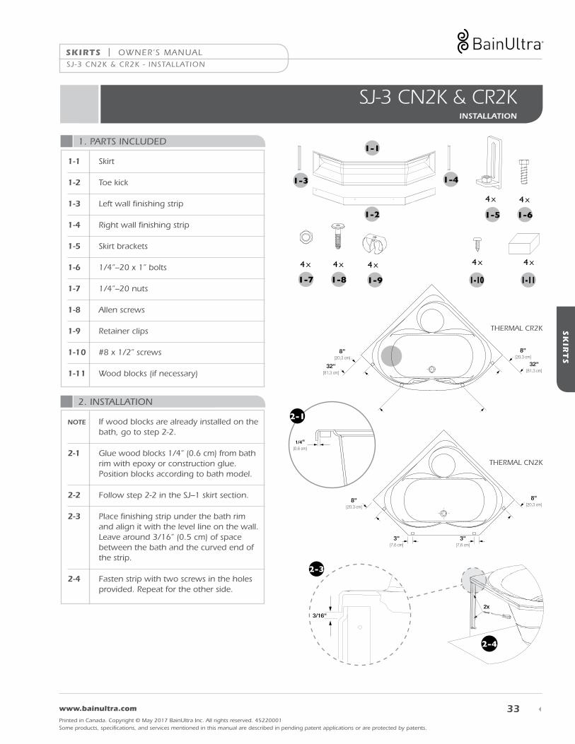
SJ-3 CN2K & CR2KINSTALLATION
1. PARTS INCLUDED
2. INSTALLATION
1-1 Skirt
1-2 Toe kick
1-3 Left wall finishing strip
1-4 Right wall finishing strip
1-5 Skirt brackets
1-6 1/4”–20 x 1” bolts
1-7 1/4”–20 nuts
1-8 Allen screws
1-9 Retainer clips
1-10 #8 x 1/2” screws
1-11 Wood blocks (if necessary)
NOTE If wood blocks are already installed on the bath, go to step 2-2.
2-1 Glue wood blocks 1/4” (0.6 cm) from bath rim with epoxy or construction glue. Position blocks according to bath model.
2-2 Follow step 2-2 in the SJ–1 skirt section.
2-3 Place finishing strip under the bath rim and align it with the level line on the wall. Leave around 3/16” (0.5 cm) of space between the bath and the curved end of the strip.
2-4 Fasten strip with two screws in the holes provided. Repeat for the other side.
1-1
1-2
1-3 1-4
1-5 1-6
1-7
B-1
x 32
B-2
x 32
B-1
x 32
B-2
x 32
1-8
4 x 4 x
4 x 4 x 4 x
1-9 1-10
4 x
1-11
4 x
8"[20,3 cm]
8"[20,3 cm]
3"[7,6 cm]
3"[7,6 cm]
8"[20,3 cm]
8"[20,3 cm]
32"[81,3 cm]
32"[81,3 cm]
8"[20,3 cm]
8"[20,3 cm]
3"[7,6 cm]
3"[7,6 cm]
8"[20,3 cm]
8"[20,3 cm]
32"[81,3 cm]
32"[81,3 cm]
THERMAL CR2K
THERMAL CN2K
1/4"[0,6 cm]
16"[xx cm]
16"[xx cm]
60"[xx cm]
B B
A
16"[xx cm]
16"[xx cm]
66"[xx cm]
20"[xx cm]
20"[xx cm]
72"[xx cm]
2-1
3/16"
2x
2-3
2-4
SJ-3 CN2K & CR2K - INSTALLATION
OWNER’S MANUAL | SKIRTS
34 1 800 463.2187 From 8 a.m. to 8 p.m. Monday to Thursday (EST) . From 8 a.m. to 5 p.m. on Friday (EST)
Printed in Canada. Copyright © May 2017 BainUltra Inc. All rights reserved. 45220001Some products, specifications, and services mentioned in this manual are described in pending patent applications or are protected by patents.
SK
IRT
S
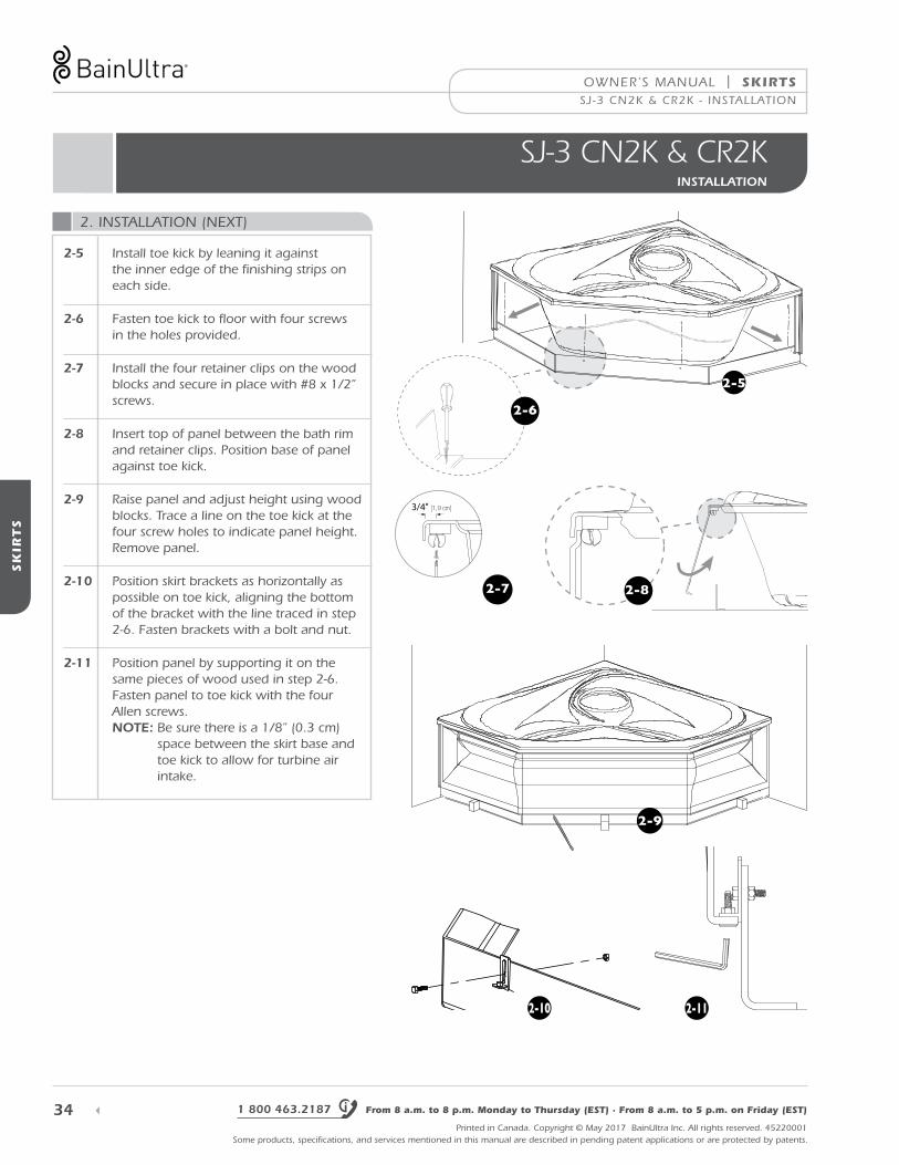
SJ-3 CN2K & CR2KINSTALLATION
2. INSTALLATION (NEXT)
2-5 Install toe kick by leaning it against the inner edge of the finishing strips on each side.
2-6 Fasten toe kick to floor with four screws in the holes provided.
2-7 Install the four retainer clips on the wood blocks and secure in place with #8 x 1/2” screws.
2-8 Insert top of panel between the bath rim and retainer clips. Position base of panel against toe kick.
2-9 Raise panel and adjust height using wood blocks. Trace a line on the toe kick at the four screw holes to indicate panel height. Remove panel.
2-10 Position skirt brackets as horizontally as possible on toe kick, aligning the bottom of the bracket with the line traced in step 2-6. Fasten brackets with a bolt and nut.
2-11 Position panel by supporting it on the same pieces of wood used in step 2-6. Fasten panel to toe kick with the four Allen screws. NOTE: Be sure there is a 1/8” (0.3 cm)
space between the skirt base and toe kick to allow for turbine air intake.
3/4" [1,9 cm]
2-8
2-9
2-10 2-11
SJ-3 CN2K & CR2K - INSTALLATION
2-7
2-5
2-6
SKIRTS | OWNER’S MANUAL
35 www.bainultra.com
Printed in Canada. Copyright © May 2017 BainUltra Inc. All rights reserved. 45220001Some products, specifications, and services mentioned in this manual are described in pending patent applications or are protected by patents.
SK
IRT
S
SK
IRT
S
1. PARTS INCLUDED
2. INSTALLATION
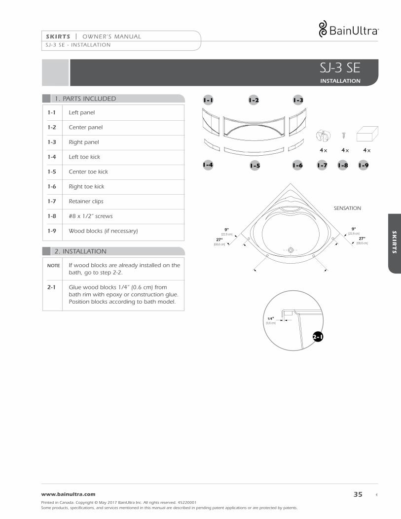
SJ-3 SE INSTALLATION
1-1
1-4
1-2
1-5
1-3
1-6
4 x 4 x4 x
1-7 1-8 1-9
11"[27,9 cm]
11"[27,9 cm]
34"[86,3 cm]
34"[86,3 cm]
9"[22,8 cm]
9"[22,8 cm]
27"[68,6 cm]
27"[68,6 cm]
SENSATION
1/4"[0,6 cm]
16"[xx cm]
16"[xx cm]
60"[xx cm]
B B
A
16"[xx cm]
16"[xx cm]
66"[xx cm]
20"[xx cm]
20"[xx cm]
72"[xx cm]
2-1
1-1 Left panel
1-2 Center panel
1-3 Right panel
1-4 Left toe kick
1-5 Center toe kick
1-6 Right toe kick
1-7 Retainer clips
1-8 #8 x 1/2” screws
1-9 Wood blocks (if necessary)
NOTE If wood blocks are already installed on the bath, go to step 2-2.
2-1 Glue wood blocks 1/4” (0.6 cm) from bath rim with epoxy or construction glue. Position blocks according to bath model.
SJ -3 SE - INSTALLATION

OWNER’S MANUAL | SKIRTS
36 1 800 463.2187 From 8 a.m. to 8 p.m. Monday to Thursday (EST) . From 8 a.m. to 5 p.m. on Friday (EST)
Printed in Canada. Copyright © May 2017 BainUltra Inc. All rights reserved. 45220001Some products, specifications, and services mentioned in this manual are described in pending patent applications or are protected by patents.
SK
IRT
S
SJ-3 SE INSTALLATION
2. INSTALLATION (NEXT)
2-2 Hold level against bath rim and mark dashes around the bath every 6’’ (15.2 cm).
2-3 Mark a second set of dashes 2’’ closer to the bath. This is where the toe kick will be.
2-4 Join the second set of dashes together. This will reproduce the bath’s curve.
2-5 Mark the center of this curve.
2-6 Position center toe kick just behind the curved line and center it by aligning the notch under it with the guideline on the floor.
2-7 Screw center toe kick to floor, starting with the two screws in the middle.
NOTE You may have to bend the toe kick slightly to match the curve drawn on the floor.
2-8 Place left and right toe kicks on either side as shown and screw to floor. NOTE: Cut left and right toe
kicks as needed.
2-9 Install the four retainer clips on the wood blocks and secure in place with #8 x 1/2” screws.
6"[15,2 cm] 2"
[5 cm]
6"[15,2 cm] 2"
[5 cm]
2-42-5
2-2
2-3
2-8
2-6
3/4" [1,9 cm]2-9
SJ-3 SE - INSTALLATION

SKIRTS | OWNER’S MANUAL
37 www.bainultra.com
Printed in Canada. Copyright © May 2017 BainUltra Inc. All rights reserved. 45220001Some products, specifications, and services mentioned in this manual are described in pending patent applications or are protected by patents.
SK
IRT
SJU
PE
S2. INSTALLATION (NEXT)
2-10 Insert top of panel between the bath rim and retainer clips. Position base of panel against toe kick.
2-11 Seat brackets on toe kick and adjust screws so that brackets are vertical.
2-12 Adjust panel height, leaving 1/4”(0.6 cm) between the edge of the bath and the curved panel top.
2-13 Ensure brackets are well seated on toe kick and tighten wing nut as much as possible.
2-14 Remove panel and follow steps 2-10 to 2-13 for the left panel.
2-15 Remove left panel and repeat steps 2-10 to 2-13 with the center panel.
2-16 Leave center panel in place and reinstall the left and right panels, inserting top of panel first. NOTE: Cut left and right toe
kicks and panels as needed.
2-10
2-11
SJ-3 SE - INSTALLATION
2-12
SJ-3 SE INSTALLATION

OWNER’S MANUAL | SKIRTS
38 1 800 463.2187 From 8 a.m. to 8 p.m. Monday to Thursday (EST) . From 8 a.m. to 5 p.m. on Friday (EST)
Printed in Canada. Copyright © May 2017 BainUltra Inc. All rights reserved. 45220001Some products, specifications, and services mentioned in this manual are described in pending patent applications or are protected by patents.
SK
IRT
S
SJ-3 TMU 5454 / 6060 INSTALLATION
1. PARTS INCLUDED
2. INSTALLATION
1-1 Left panel
1-2 Center panel
1-3 Right panel
1-4 Left toe kick
1-5 Center toe kick
1-6 Right toe kick
1-7 Acrylic footing*
1-8 Wood insert*
1-9 Upper bracket
1-10 Lower bracket
1-11 5/32” Allen key
1-12 Cutting template
1-13 Round head Allen screw
1-14 No. 8 x 1/2” screws
1-15 No. 8 x 2 1/2” screws and washers*
* Parts 1.7, 1.8, and 1.15 are only included for skirts ordered with the step.
2-1 Screw upper brackets into factory-installed wood blocks. Brackets must be flush with the bath edge.
2-2 Follow step 2-1 in the SJ-1 skirt section.
2-3 Cut out cutting template and place it on floor, aligning the arrow marked “level” with the line traced on the wall.
1-1
1-4
1-2
1-5
1-3
1-6
1-8
1-7
1-9 1-10 1-13
A-2
A-5
A-7
A-7
A-8
A-1
A-2
A-3
A-6
A-3
A-4
A-13
A-12
A-91-11 1-14 1-151-12
6 x 6 x 12 x 2 x6 x
2-1
2-3
SJ-3 TMU 5454/6060 - INSTALLATION

SKIRTS | OWNER’S MANUAL
39 www.bainultra.com
Printed in Canada. Copyright © May 2017 BainUltra Inc. All rights reserved. 45220001Some products, specifications, and services mentioned in this manual are described in pending patent applications or are protected by patents.
SK
IRT
S
SK
IRT
S
2. INSTALLATION (NEXT)
2-4 Align the center, left, and right toe kicks with the cutting template. Ensure center toe kick is exactly centered.
2-5 Screw toe kicks to floor and remove template.
2-6 Screw lower brackets into the predrilled holes on the center panel using Allen screws. NOTE: Do not tighten. Final tightening is
done in the next step.
2-7 Hook the center panel lower bracket on the center toe kick. Push panel against the upper bracket and slide under bath rim.
2-8 Tighten Allen screw on each lower bracket to leave 3/16” (0,5 cm) of space, as shown in the illustration.
2-9 Repeat steps 2.6 to 2.8 for the left and right panels.
2-10 Leave 3/16” (0,5 cm) of space on each side of the center panel.
2-11 If you ordered the step, place acrylic footing along the toe kick, center and screw to the floor.
2-12 Place wood insert on footing.
2-4
2-62-7
3/16’’[0,5 cm]
2-8
3/16"
3/16"
2-10
2-11
2-5
SJ-3 TMU 5454/6060 - INSTALLATION
SJ-3 TMU 5454 / 6060 INSTALLATION

OWNER’S MANUAL | SKIRTS
40 1 800 463.2187 From 8 a.m. to 8 p.m. Monday to Thursday (EST) . From 8 a.m. to 5 p.m. on Friday (EST)
Printed in Canada. Copyright © May 2017 BainUltra Inc. All rights reserved. 45220001Some products, specifications, and services mentioned in this manual are described in pending patent applications or are protected by patents.
SK
IRT
S
MERIDIAN DUO
INSTALLATION
1. INCLUDED PARTS
2. INSTALLATION
1-1 Meridian Duo bath
1-2 Meridian Duo skirt
2-1 Insert upper part of skirt with top hooks holding the upper part of bath frame.
2-2 Lower skirt in order for hooks to rest against lower part of bath frame.
Adjust the height of skirt by raising or lowering the lower hooks and securing them into place at the desired height by using the provided wing nuts.
1-2
1-1
2-1
MERIDIAN DUO - INSTALLATION
2-2

THE MIA® SERIES CONTROLS | OWNER’S MANUAL
41 www.bainultra.com
Printed in Canada. Copyright © May 2017 BainUltra Inc. All rights reserved. 45220001Some products, specifications, and services mentioned in this manual are described in pending patent applications or are protected by patents.
TH
E M
IA® S
ER
IES C
ON
TR
OL
S
MIA® & MIAPLUS® CONTROLSINSTALLATION
Determine the most convenient location, on either the wall or the deck, to install the control module or consult the specifications sheet for the suggested location. To avoid drilling in an air intake zone or an electric component, always check under the deck before drilling. If you have to install the control to the wall, remove the protective film of sticker behind the control. You can add a silicone bead to secure it.
Refer to the drilling template on the last page for the location and diameter of the holes.
LOCATION
DRILLING
INSTALLING THE TOUCHPAD
REQUIRED TOOLS
1 Push wiring through drilled holes.
2 Remove protective film from watertight seal.
3 Secure touchpad into place on either the podium or the wall by using 2, 8-32 x 1” studs and 2 wing nuts.
4 Tighten sufficiently to insure seal is airtight.
1 Fine teeth jigsaw
2 Drill
3 1/4 in. drill bit
• If control was not factory-installed, it will be attached to the turbine.WARNING
MIA® & MIAPLUS® CONTROLS - INSTALLATION

42
OWNER’S MANUAL | THE MIA® SERIES CONTROLS
1 800 463.2187 From 8 a.m. to 8 p.m. Monday to Thursday (EST) . From 8 a.m. to 5 p.m. on Friday (EST)
Printed in Canada. Copyright © May 2017 BainUltra Inc. All rights reserved. 45220001Some products, specifications, and services mentioned in this manual are described in pending patent applications or are protected by patents.
TH
E M
IA® S
ER
IES C
ON
TR
OL
S
MIA®
USER GUIDE
• Increase or decrease air jet pressure• Activate Drying cycle function
MAIN FUNCTIONS
ON/OFF
On
Press the (on/off) key to start or to stop the tur-bine and the Mia® control panel.
ADJUST AIR JET PRESSURE
TO ACTIVATE THE DRYING CYCLE
Air jet pressure can be adjusted for maximum comfort and a remarkably effective massage. Default pressure is set to 60%.
Increase or decrease the pressure of the air jets by repeatedly pressing the or keys until the desired intensity is reached.
This function completely drains the conduits and dries them for 90 seconds, regardless of whether or not the system was activated. By eliminating any water left in the conduits, the Drying cycle ensures perfect hygiene.
• No stagnant water
• No water left over from the previous bath
To activate the Drying cycle, press . The operation will cease after 90 seconds. If you do not activate the function, the drying process will begin automatically after 15 minutes. If the bath is used for soaking only, activate the drying cycle manually by pressing . You can use the Drying cycle function immediately after a Hydro-thermo massage® session or whenever you wish.
NOTE • The heat for the heated backrest is controlled simultaneously with the intensity of the jet pressure.
MIA® - USER GUIDE

THE MIA® SERIES CONTROLS | OWNER’S MANUAL
43 www.bainultra.com
Printed in Canada. Copyright © May 2017 BainUltra Inc. All rights reserved. 45220001Some products, specifications, and services mentioned in this manual are described in pending patent applications or are protected by patents.
TH
E M
IA® S
ER
IES C
ON
TR
OL
S
MIAPLUS® - USER GUIDE
MIAPLUS®
USER GUIDE
Settings are automatically saved until they are modified.
MiaPlus® lets you personalize your Hydro-thermo massage® with the following functions and options:• Adjust air jet pressure• Select duration of session• Select light color (Chromatherapy option)• Adjust backrest temperature• Personalize session settings for up to 4 different users• Personalize drying cycle for water jet conduits• Lock controls when bath is not in use• Adjust screen contrast• Select display language
MAIN FUNCTIONS
KEYS AND FUNCTIONS
Press this key to start or to stop the turbine and the MiaPlus® control panel.
Press this key to return to function adjustment. The Massage function appears on the screen by default.
Press either of these keys to navigate the main menu of the MiaPlus® control panel.
Press the key to see the next function.
Functions are displayed in the following order:
• Massage (air jet pressure)
• Duration
• Chroma (Chromatherapy option)
• Backrest (heated backrest)
• Care
• Save
• Drying cycle
• Lock
• Contrast (screen contrast)
• Language
• Contact us
Press either of these keys to navigate the options of each function.
Press the key to go up.
Press the key to go down.
Press this key to save the selected options and settings.

44
OWNER’S MANUAL | THE MIA® SERIES CONTROLS
1 800 463.2187 From 8 a.m. to 8 p.m. Monday to Thursday (EST) . From 8 a.m. to 5 p.m. on Friday (EST)
Printed in Canada. Copyright © May 2017 BainUltra Inc. All rights reserved. 45220001Some products, specifications, and services mentioned in this manual are described in pending patent applications or are protected by patents.
TH
E M
IA® S
ER
IES C
ON
TR
OL
S
MIAPLUS®
USER GUIDE
MASSAGE
DURATION
CHROMA (OPTION)
• Off Deactivates the chromatherapy function.
• Violet Immunizing and relaxing. Boosts the immune system, detoxifies the body, and reduces stress.
• Blue Soothing and relaxing. Reduces arterial pressure and hyperactivity and soothes the soul.
• Green Provides calm and balance. Relaxes entire body and stabilizes emotions.
• Yellow Digestion and creativity. Helps digestion and regularity and calms brain activity.
• Orange Healing and pain relief. Boosts respiratory system and soothes aching muscles.
• Red Stimulating and exciting. Activates circulation and wakes up the senses.
• Scan Goes through each color in turn.
THE CHROMA FUNCTION FEATURES EIGHT OPTIONS
This function allows the user to regulate air jet pressure for personalized comfort and a remarkably effective Hydro-thermo massage®. The default pres-sure is the same for the previous bath.
Increase or decrease the pressure of the air jets by repeatedly pressing the or key until the desired pressure is reached. Pressure increases in 10% increments.
Pressing is optional.
This function lets you program the duration of your bath from 5 to 30 minutes. The selected duration will remain in the memory until it is modified.
To select the Duration, press the key on the menu until the Duration function is displayed.
Select the desired duration using the or keys.
Pressing is optional.
Use the arrows or or the key to return to the basic Massage screen.
This function uses color to provide increased comfort to body and soul.
To use the Chroma function, press the key on the menu until the Chroma function appears on the screen.
• To turn off the Chroma function, select Off. screen.
• The Chroma function will turn off by itself after 4 hours.
NOTE • Should you not see the colors on the screen, pressing the first time will start the color scan.Pressing a second time will freeze the lights on their color, and the third time will turn the lights off.
MIAPLUS® - USER GUIDE

THE MIA® SERIES CONTROLS | OWNER’S MANUAL
45 www.bainultra.com
Printed in Canada. Copyright © May 2017 BainUltra Inc. All rights reserved. 45220001Some products, specifications, and services mentioned in this manual are described in pending patent applications or are protected by patents.
TH
E M
IA® S
ER
IES C
ON
TR
OL
S
CHROMA (NEXT)
Choosing a color
Choose the desired color using the and keys.
Press to validate your choice of color.
Selecting Scan
Select the Scan option using the or keys.
Press to validate your choice.
Use the arrows or or the key to return to the basic Massage screen.
BACKREST
For maximum relaxation and exceptional comfort, one or two heated backrests can be installed in your bath and heated individually.
Select the Backrest function by pressing the key until the Backrest function is displayed.
Four options are available:
• Off
• Low
• Medium
• High
NOTE: Models with 2 backrests will specify backrest 1 and backrest 2.
Choose the desired option using the or keys.
Press to validate your choice.
Use the arrows or or the key to return to the basic Massage screen.
NOTE: Selecting the Off option will turn off the backrests.
MIAPLUS®
USER GUIDE
MIAPLUS® - USER GUIDE

46
OWNER’S MANUAL | THE MIA® SERIES CONTROLS
1 800 463.2187 From 8 a.m. to 8 p.m. Monday to Thursday (EST) . From 8 a.m. to 5 p.m. on Friday (EST)
Printed in Canada. Copyright © May 2017 BainUltra Inc. All rights reserved. 45220001Some products, specifications, and services mentioned in this manual are described in pending patent applications or are protected by patents.
TH
E M
IA® S
ER
IES C
ON
TR
OL
S
CARE
SAVE
This function lets you vary air jet intensity for a deeper or gentler massage.
To select the Care function, press the key on the menu until the Care function appears.
Six options are available: • Massage – Even intensity throughout the session
• Wave – Jet intensity cycles from 10% to maximum desired intensity
• Bather 1, 2, 3, 4 – Stores each bather’s selection
Use the or keys to select an option.
Press to validate your choice.
Use the arrows or or the key to return to the basic Massage screen.
The MiaPlus® control system lets you save up to four personalized presets. This save function lets you conveniently preselect settings adapted to various users or purposes. Simply set the functions and options according to your tastes and save them under Bather 1, Bather 2, etc. These personalized settings will stay saved until modified.
Select a bather and save personalized settings
Press the key on the menu until the Save function appears.
Use the or keys to select a user number.
Press .
Use the arrows or or the key to return to the basic Massage screen.
Repeat these steps for each user.
MIAPLUS®
USER GUIDE
MIAPLUS® - USER GUIDE

THE MIA® SERIES CONTROLS | OWNER’S MANUAL
47 www.bainultra.com
Printed in Canada. Copyright © May 2017 BainUltra Inc. All rights reserved. 45220001Some products, specifications, and services mentioned in this manual are described in pending patent applications or are protected by patents.
TH
E M
IA® S
ER
IES C
ON
TR
OL
S
DRYING CYCLE
This function completely drains the conduits and dries them for 90 seconds. By eliminating any water left in the conduits, the Drying cycle ensures perfect hygiene.
• No stagnant water
• No water left over from the previous bath
Drying is mandatory after a Hydro-thermo massage® session.
Two options are available:
• Daily
• After Bath
Even when the daily drying cycle is programmed, the automatic drying cycle will activate after each use.
Select After BathThe After Bath option lets you program the Drying cycle to start up to 60 minutes after a bath.
To select the After Bath option, press the key on the menu until the Drying cycle function appears.
Use the and keys to select the After Bath option.
Press .
Dry Delay is displayed.
Press the key to select a value from 5 to 60 minutes.
Press to validate.
Use the arrows or or the key to return to the basic Massage screen.
If no value is selected, the Drying cycle will start up automatically 15 minutes after the bath.
MIAPLUS®
USER GUIDE
MIAPLUS® - USER GUIDE

48
OWNER’S MANUAL | THE MIA® SERIES CONTROLS
1 800 463.2187 From 8 a.m. to 8 p.m. Monday to Thursday (EST) . From 8 a.m. to 5 p.m. on Friday (EST)
Printed in Canada. Copyright © May 2017 BainUltra Inc. All rights reserved. 45220001Some products, specifications, and services mentioned in this manual are described in pending patent applications or are protected by patents.
TH
E M
IA® S
ER
IES C
ON
TR
OL
S
DRYING CYCLE (NEXT)
Select DailyThe Daily option lets you dry and clean the air jet system conduits at a specific time of day rather than within an hour of a Hydro-thermo massage® session.
To select the Daily option, press the key on the menu until the Drying cycle option appears.
Use the and keys to select the Daily option.
Press .
Start Time is displayed.
Use the or keys to select the time of day the Drying cycle function should start.
Press .
Current Time is displayed.
Press and hold the or keys or press them repeatedly to set the preprogrammed current time in 10 minute slots.
Press .
Once the Daily option is set, the Drying cycle will start every day at the same time until the setting is modified.
Use the arrows or or the key to return to the basic Massage screen.
NOTE: The time format is preset as follows:
French: 24 hourEnglish: 12 hour (AM and PM)Spanish: 24 hour
MIAPLUS®
USER GUIDE
MIAPLUS® - USER GUIDE

THE MIA® SERIES CONTROLS | OWNER’S MANUAL
49 www.bainultra.com
Printed in Canada. Copyright © May 2017 BainUltra Inc. All rights reserved. 45220001Some products, specifications, and services mentioned in this manual are described in pending patent applications or are protected by patents.
TH
E M
IA® S
ER
IES C
ON
TR
OL
S
LOCK
CONTRAST
This function lets you lock the control system in order to prevent the turbine from starting unexpectedly or accidentally.
It is also a child safety device, as it prevents children from starting the turbine by pressing the key.
To activate the Lock function
Press the key on the menu until the Lock function appears.
Use the or keys to select the Activate option.
Press to validate your choice.
When you stop the bath, the Lock function locks the
key, making it impossible to restart the turbine.
To restart the turbine when the Lock function is activated
Press the key.
Lock is displayed. Press .
The turbine starts.
To deactivate the Lock function
Press the key on the menu until the Lock function appears.
Use the and keys to select the Off option.
Press .
This function controls the brightness of the MiaPlus® display screen. No matter which setting you select, the screen is always clear and easy to read from any angle, regardless of the lighting conditions of the room where your bath is installed.
MIAPLUS®
USER GUIDE
MIAPLUS® - USER GUIDE

50
OWNER’S MANUAL | THE MIA® SERIES CONTROLS
1 800 463.2187 From 8 a.m. to 8 p.m. Monday to Thursday (EST) . From 8 a.m. to 5 p.m. on Friday (EST)
Printed in Canada. Copyright © May 2017 BainUltra Inc. All rights reserved. 45220001Some products, specifications, and services mentioned in this manual are described in pending patent applications or are protected by patents.
TH
E M
IA® S
ER
IES C
ON
TR
OL
S
CONTRAST (NEXT)
LANGUAGE
Feel free to contact Bain Ultra for any information you may need about your Thermomasseur® bath and the MiaPlus® control system. Simply call the telephone number that appears on this screen for answers to any question.
1.800.463.2187
BainUltra® wishes you complete relaxation!
CONTACT US
NOTE: The screen automatically dims after 2 minutes.
To set display screen contrast, press the or key on the menu until the Contrast function appears.
NOTE: Use the key to access this function more quickly when you start the turbine.
Press or until the desired percentage (%) of contrast is displayed.
Press to validate your choice.
Use the arrows or or the key to return to the basic Massage screen.
The MiaPlus® control system lets you select one of the following three display languages: • French • English • Spanish
NOTE: The factory-selected language is English.
To choose the display language, press the or key on the menu until the Language function appears.
NOTE: Use the key to access this function more quickly when you start the turbine.
Press or to select your desired language.
Press .
Use the arrows or or the key to return to the basic Massage screen.
MIAPLUS®
USER GUIDE
MIAPLUS® - USER GUIDE

THE MIA® SERIES CONTROLS | OWNER’S MANUAL
51 www.bainultra.com
Printed in Canada. Copyright © May 2017 BainUltra Inc. All rights reserved. 45220001Some products, specifications, and services mentioned in this manual are described in pending patent applications or are protected by patents.
TH
E M
IA® S
ER
IES C
ON
TR
OL
S
MIAMULTI®
USER GUIDE
The MiaMulti® control features the same functions as the MiaPlus®, but also comes with a convenient and easy-to-use remote control. You enjoy all the benefits of a personalized Hydro-thermo massage® without having to leave the bath. Just lie back and relax!
MIAMULTI®
NOTE: To work efficiently, the remote must be pointed toward the MiaMulti® wall-mounted control in the room where your bath is.
1. Key Operates the remote
2. Backrest 1 + key
Increases the temperature of backrest 1
3. Backrest 1 – key
Decreases the temperature of backrest 1
4. Backrest 2 + key
Increases the temperature of backrest 2
5. Backrest 2 – key
Decreases the temperature of backrest 2
6. Blower + key
Increases air jet pressure
7. Blower – key
Decreases air jet pressure
8. Duration key
Selects bath duration. Press the key to increase bath duration. Each time you press the key, your bath time increases 5 minutes, to the nearest round number.
9. Chroma key
Selects the chromatherapy function. To change the color, press the key until the desired color is displayed.
BATHBAIN
1
2 6
73
4
5
8
9
REMOTE - HYDRO-THERMO MASSAGE®
MIAMULTI® - USER GUIDE

52
OWNER’S MANUAL | THE MIA® SERIES CONTROLS
1 800 463.2187 From 8 a.m. to 8 p.m. Monday to Thursday (EST) . From 8 a.m. to 5 p.m. on Friday (EST)
Printed in Canada. Copyright © May 2017 BainUltra Inc. All rights reserved. 45220001Some products, specifications, and services mentioned in this manual are described in pending patent applications or are protected by patents.
TH
E M
IA® S
ER
IES C
ON
TR
OL
S
MIAMULTI®
USER GUIDE
NOTE: To work efficiently, the remote must be pointed toward the MiaMulti® wall-mounted control in the room where your bath is.
BATHBAINBATHBAINBATHBAIN
Red light
PROGRAMMING MIAMULTI® - BATH
Press key BATH/BAIN
Press key MINUS and keep it pushed.
Press key POWER and keep both keys pushed for 2 seconds.
Once red light is switched on, release both keys.
Immediately press keys sequence:
Red light will switch off at every key.
Once sequence is terminated, red light will stay switch off.
PROGRAMMING PROCEDURE FOR REMOTE CONTROLLER 2011 AND UP
BATHBAIN
MIAMULTI® - USER GUIDE

MAINTENANCE | OWNER’S MANUAL
53 www.bainultra.com
Printed in Canada. Copyright © May 2017 BainUltra Inc. All rights reserved. 45220001Some products, specifications, and services mentioned in this manual are described in pending patent applications or are protected by patents.
MA
INT
EN
AN
CE
MAINTENANCE
The BainUltra® ThermoMasseur® is as simple to care for as a conventional acrylic bath. There are no pumps, valves, pipes, nor accessories to take apart or clean. Thanks to its design, the system is perfectly hygienic and completely dry. The automatic and programmable drying cycles completely empty the air channel. No standing water. Nothing left over from the previous bath. The user does not have to worry about the air channels nor the turbine. Simply clean the surface of the bath with a non-abrasive cleanser.
Technical information
• All BainUltra® ThermoMasseurs® are made of Lucite acrylic.
Maintenance
• Clean acrylic with a mild non-abrasive product.
• Abrasive products such as powder, paint thinners, terpentine and gas can damage the shine and lustre of the acrylic.
• For particularly tough stains, use a small amount of wood alcohol (methyl hydrate).
Safety instructions
• When applying wood alcohol (methyl hydrate), use gloves to protect hands. Rince thoroughly after use.
• Ensure that essential oils or other therapeutic products added to bath water will not damage the acrylic finish.
Maintenance
• For minor surface damage, use a polishing putty for acrylic surfaces or automobiles.
Safety instructions
• Follow polish manufacturers’ instructions.
ACRYLIC
ACRYLIC (MINOR REPAIRS)
IMPORTANT • Any product added to your ThermoMasseur® must be dissolved in the water or if not, be mixed with an emulsifier (see the Therapy Guide for more details) in order to ensure the longevity of your bath’s acrylic as well as the efficiency of its system, along with the exceptional quality of care offered by your BainUltra® bath.
Table - Sandpaper grade
Égratignure
Papier grade 220
Papier grade 400
Papier grade 600
Papier grade 800
Papier grade 1200
Polissage
Scratch
Paper grade 220
Paper grade 400
Paper grade 600
Paper grade 800
Paper grade 1200
Polish

54
OWNER’S MANUAL | MAINTENANCE
1 800 463.2187 From 8 a.m. to 8 p.m. Monday to Thursday (EST) . From 8 a.m. to 5 p.m. on Friday (EST)
Printed in Canada. Copyright © May 2017 BainUltra Inc. All rights reserved. 45220001Some products, specifications, and services mentioned in this manual are described in pending patent applications or are protected by patents.
MA
INT
EN
AN
CE
MAINTENANCE
ACRYLIC (DEEPER SCRATCHES)
Technical information
• An automatic drying cycle starts 10 minutes after each use ensuring the dryness of the channel.
• It is normal to hear the turbine working at a certain time of day. This means that the drying cycle has been programmed.
Maintenance
• BainUltra® recommends to start the drying cycle everytime the bath is used as a shower or just to soak.
SYSTEM
Maintenance
• For slightly deeper scratches, sand the spot with a wet sandpaper before polishing.
• Depth of abrasion or scratch will determine grade of sandpaper required:
- Slight to moderate damage — grade 600, 800, then 1200 sandpaper
- Deeper damage — grade 400, 600, 800, then 1200 sandpaper
• When sanding, start with lowest grade sandpaper (e.g. 400), working your way up as you sand a slightly larger area with each new grade. Finish with polishing putty.
Technical information
• The cedar wood components (step and/or shelf) are protected by a highly durable and resilient coat of catalyzed polyurethane.
• This protective coating is designed for a high humidity environment and ensures a long-lasting, stain and water resistant finish.
CEDAR WOOD (TMU 5454/6060)
Maintenance
• To protect the wood finish, do not leave any soaps or detergents on wood surfaces for long periods of time.
• Clean the wood with mild soap and a cotton cloth. Do not use abrasive or corrosive products.

TR
OU
BL
ESH
OO
TIN
G
TROUBLESHOOTING | OWNER’S MANUAL
55 www.bainultra.com
Printed in Canada. Copyright © May 2017 BainUltra Inc. All rights reserved. 45220001Some products, specifications, and services mentioned in this manual are described in pending patent applications or are protected by patents.
TROUBLESHOOTING
Your BainUltra® ThermoMasseur® has been manufactured and inspected with the greatest care. In addition, it has been thoroughly tested on a test bench to offer you a product of superior quality satisfying your highest expectations. The following troubleshooting chart will assist you in correcting a problem. If you continue to have problems, contact your retailer or the manufacturer.
Your bath will not start.
Breaker trips continually.
Turbine stops working after only a few minutes.
A few airjets do not work at lowest speeds.
• Make sure breaker is “ON.”
• Shut off and restart breaker.
• Check junction box connections to bath (for Canada only).
• Make sure that your bath is the only appliance connected to circuit.
• Check for a short circuit between bath and breaker box.
• Breaker may too sensitive, defective or old. Try a new breaker. This component must be new.
Turbine and air-heater are equipped with heat sensors designed to cut off power in case of overheating. Insufficient air circulation may be the cause.
• Make sure turbine has sufficient ventilation.
• Make sure turbine intake is not obstructed.
To meet everyone’s needs, particularly those of children, your bath is designed to work at a very low speed. Air jets in half-seat or those closest to drain in TMU models, especially larger models, may remain inactive at lowest speeds. This is normal and can be easily remedied by slowly raising speed to “open” inactive air jets and then lowering it to desired level. Furthermore, your bath is pre-programmed in the factory at a low, regular or high intensity depending on the size. To change the intensity level, please contact BainUltra® directly. Certain conditions may amplify this occurrence.
• Check for turbine intake obstruction, too great a distance between turbine and bath, too many directional changes (elbows), and, if adequate piping has been used. See TURBINE RELOCATION paragraph.
SITUATION SOLUTIONS

TR
OU
BL
ESH
OO
TIN
G
56
OWNER’S MANUAL | TROUBLESHOOTING
1 800 463.2187 From 8 a.m. to 8 p.m. Monday to Thursday (EST) . From 8 a.m. to 5 p.m. on Friday (EST)
Printed in Canada. Copyright © May 2017 BainUltra Inc. All rights reserved. 45220001Some products, specifications, and services mentioned in this manual are described in pending patent applications or are protected by patents.
TROUBLESHOOTING
SITUATION SOLUTIONS
Air jets seem cool.
LED does not work.
Temperature of air injected into bath is directly proportional to the speed of the turbine. The higher the speed, the warmer the air is. A simple way to check if your air-heater or heaters are working properly is to turn on the system at the highest speed (if your control offers a range of intensities) with no water in the bath (there is absolutely no risk to the system). After 3 to 5 minutes, the heated backrest or backrests should be warm to the touch and jets should also seem warm when you bring your hands close to them.
• Check the turbine air intake. It should not be too cold nor too warm. Ideally, the temperature should be between 72°F (20°C) and 86°F (30°C).
• Check that distance between turbine and bath is not too great. If possible, insulate air line along its entire length. See turbine installation section of this manual.
An LED has a 100 000-hour lifecycle. • Verify wiring and connections.
IMPORTANT: THESE INSTRUCTIONS ONLY APPLY IF THE LED CAN BE ACCESSED FROM BATH EXTERIOR.
• Upon verification, if LED still does not work, disconnect and replace the LED by doing the following:
- Remove the LED module by pulling on the white part of the plug. If the module is difficult to remove, use a pair of vice-grips.
- Detach the wire from the bath.
- Unplug the wire from the chromatherapy control module.
- Plug the wire into the chromatherapy control module.
- Plug the LED module back into its socket.
NOTE: IT IS NOT NECESSARY TO REATTACH THE WIRE TO THE BATH.

WARRANTY | OWNER’S MANUAL
57 www.bainultra.com
Printed in Canada. Copyright © May 2017 BainUltra Inc. All rights reserved. 45220001Some products, specifications, and services mentioned in this manual are described in pending patent applications or are protected by patents.
WA
RR
AN
TY
WA
RR
AN
TY
WA
RR
AN
TY
WA
RR
AN
TY
THE BAINULTRA® LIMITED WARRANTYBAINULTRA® THERMOMASSEUR® & THERMASENS®: 20 YEARS, VEDANA®: 5 YEARS
LIMITED WARRANTY
This limited warranty is extended only to the original purchaser of the unit who has possession of his or her receipt of purchase, and is valid only when the unit has been purchased through an authorized Bains Ultra Inc. (“BainUltra®”) retailer and has been registered with BainUltra® (registration not required for consumer purchasers domiciled in the Province of Québec). This warranty is not transferable under any circumstance. Please note that you are responsible for inspecting the product and all parts prior to installation. This warranty will not apply if a product with visible defects has been installed without providing notice to BainUltra® of the defect.
Your BainUltra® ThermoMasseur®, ThermaSens® or soaking bath is covered by the best warranty in the industry. BainUltra® guarantees the acrylic and motor turbine of your bath for a twenty-(20) year period from the original purchase date against defects in materials and workmanship.
In the case of the electronic components of the therapeutic baths parts of the Vedana® and the new technologies Geysair, AromaCloud®, WarmTouchShell and Chromatherapy. BainUltra® guarantees against defects in materials and workmanship for a five-(5) year period from the original purchase date.
Towel bars, grab bars and claw feet are guaranteed for a two-(2) year period.
The wastes and overflows are guaranteed for a one-(1) year period from the original purchase date.
The Akasa Bath Pillow and Comfort Cushion are guaranteed for a two (2) year period.
For the wooden complementary product Akasa (Chair, footrest, legrest, espalier), BainUltra® guarantees that, in their original manufacturing form, these parts are free of any manufacturing, dimensional or strongly apparent natural defects for a one-(1) year period from the original purchase date.
Tile flanges are guaranteed prior to installation only.
BainUltra® products are designed for residential use only. BainUltra® products used for commercial or display applications will be limited to a two-(2) year warranty against defects in materials and workmanship regardless of the specific nature of any potential defects.
BainUltra® products sold outside of North America will be limited to a parts-only warranty through the dealer of the sale. Our service department will help diagnose any problems with your unit and will provide parts only for repairs or replacements covered by the warranty. All parts will be shipped to the dealer in North America. BainUltra® will not be responsible for cost of shipping or servicing outside of North America. Any part that must be changed during the warranty period will be covered by the original warranty or for a two-(2) year period following replacement, according to the first contingency.
EXCLUSIONS
The above-stated limited warranty applies as long as: i) the damage is not caused by an accident, abuse, misuse, fire, insects, use of abrasive products, force majeure or an act of God. The above-stated limited warranty does not apply to:
i) Transport, handling or installation damages; or ii) wood components that will, because of their organic nature, expand when exposed to seasonal changes, normal heating variations and normal exposure to sunlight which will slightly alter the wood tint.
Moreover, this warranty is void if: i) your BainUltra® ThermoMasseur® bath, ThermaSens® bath, your Vedana®, or any other BainUltra® product is installed by anyone other than a licensed contractor; ii) your BainUltra® bath, your Vedana®, or any other BainUltra® product or part thereof has been modified or if any repairs have been attempted by anyone other than BainUltra®, an authorized BainUltra® dealer, or other representative of BainUltra®; or iii) the unit is installed outdoors, or has not been installed in accor-dance with BainUltra®’s instructions, or in compliance with local codes and ordinances.
Because of their organic nature, wood components will expand and contract with seasonal changes and normal heating variations. With time, normal exposure to sunlight will slightly alter the wood tint. These changes are not covered by the warranty.
Any and all components that are not provided by BainUltra®, as well as any items attached or installed on your BainUltra® ThermoMasseur®, ThermaSens® bath , your Vedana®, or on any other BainUltra® product after the date of manufacture are expressly excluded from this limited warranty.
This limited warranty does not cover any breakage and/or damage resulting from improper (non-factory) installation of AromaCloud® technology. For further information, refer to the AromaCloud® Localisation document.
PROCEDURE
Any defect involving BainUltra®’s potential liability under this limited warranty shall be reported to BainUltra® within ten (10) days of its occurrence. To assist you with your warranty, please contact BainUltra®’s customer service by email, telephone or fax between 8 a.m. to 8 p.m.
Monday to Thursday (EST) or 8 a.m. to 5 p.m. on Friday (EST). Email: [email protected] Tel.: 1 800 463-2187 or 418 831-7701 Fax: 1 800 382-8587 or 418 831-6623 BainUltra Inc. 956, chemin Olivier Lévis, Québec Canada G7A 2N1
Proof of purchase and date of purchase will be required. Units claimed to be defective shall be held until inspected by an authorized representative of BainUltra®, and upon their specific instructions, units found to be defective will be repaired or replaced at BainUltra®’s exclusive choice. The liability of BainUltra® with respect to the sale of this unit shall be limited to repair or replacement by a similar product as provided above and does not include any cost of removal, reinstallation, transport and shipping of defective product, loss of time, salary or any other expenses as well as any consequential damages of any kind.
BainUltra® and its representatives shall not be liable for any injury, loss, cost or other damage, whether direct, consequential, incidental, or special, that arise from any defect covered under this limited warranty, even if BainUltra® has been advised of the possibility of such damage. Some states and provinces may not allow the exclusion or limitation of incidental or consequential damages, so the above limitation or exclusion may not apply to you, but these limitations or exclusions will be enforced to the maximum extent of the law.
An adequate access way to mechanical and electrical parts of your BainUltra® ThermoMasseur® bath, ThermaSens® bath, your Vedana®, or any other BainUltra® product must be anticipated and prepared before an authorized representative arrives on the premises to carry out a repair. The costs incurred to provide access to the motor turbine, the electronic module or the heating system will not be covered by this warranty.
LIMITATIONS
Except for consumer purchasers domiciled in the Province of Québec, and except to the extent prohibited by applicable law, this limited warranty replaces all other warranties, expressed or implied, in fact or at law, including implied warranties based on course of dealing, usage of trade, and merchantability and fitness for a particular purpose. (Inapplicable in Québec). The terms of this limited warranty cannot be modified or extended in any way whatsoever by any agent, dealer, distributor, service company or party other than BainUltra®.
BainUltra® excludes any statement in any advertisement or instruction, any picture, or any guideline as an express warranty for our products. We recognize that some states and provinces may not allow limitations on implied warranties, so the above limitations and exclusions may not apply to you, but they will be enforced to the maximum extent of the law.
LEGAL RIGHTS
This limited warranty gives specific legal rights and is not applicable if it interferes with any law or regulation in any state, province or country.


DRILLING TEMPLATES | OWNER’S MANUAL
59 www.bainultra.com
Printed in Canada. Copyright © May 2017 BainUltra Inc. All rights reserved. 45220001Some products, specifications, and services mentioned in this manual are described in pending patent applications or are protected by patents.
DR
ILL
ING
TE
MP
LA
TE
S
MIA®
DRILLING TEMPLATES
4.094"± 0.04”
5.125” [13.0 cm
]
0.438” [ 1.1 cm
]
3.938"± 0.04”
[10.0 cm ±
0.1 cm]
[10.4 cm ±
0.1 cm]
1.094"± 0.04”
[2.8 cm ±
0.1 cm]
1.688” [4.3 cm
]
Hole C
ontour
Control C
ontour
Drawing of Mia® Control hole
IMPORTANT Drawing is to scale.
MIA® - DRILLING TEMPLATES


DRILLING TEMPLATES | OWNER’S MANUAL
61 www.bainultra.com
Printed in Canada. Copyright © May 2017 BainUltra Inc. All rights reserved. 45220001Some products, specifications, and services mentioned in this manual are described in pending patent applications or are protected by patents.
DR
ILL
ING
TE
MP
LA
TE
S
MIAPLUS® & MIAMULTI®DRILLING TEMPLATES
5.125” ± 0.04”
[13.0 cm ±
0.1 cm]
1.625” ± 0.04”
[4.1 cm ±
0.1 cm]
5.591” [14.2 cm
]
R.250” TYP 4
[R 0.6 cm]
2.165” [5.5 cm
]
Hole C
ontour
Control C
ontour
0.875”(2.2 cm)
1 (3.5
cm
).3
75”
R 0.125”(R 0.3 cm)
1(2.9 cm)
.125”
1 (4.1
cm
).6
25”
Drawing of IR hole for MiaMulti®
IMPORTANT Drawing is to scale.
Drawing of MiaPlus® and MiaMulti® control hole (same template).
IR could be installed at arms reach or maximum up to 15 feet away from the bath.
MIAPLUS® & MIAMULTI® - DRILLING TEMPLATES