Embed Size (px)
Citation preview
SAX-125.2
SAX-50.4
SAX-100.4
Owner's manual
-2-
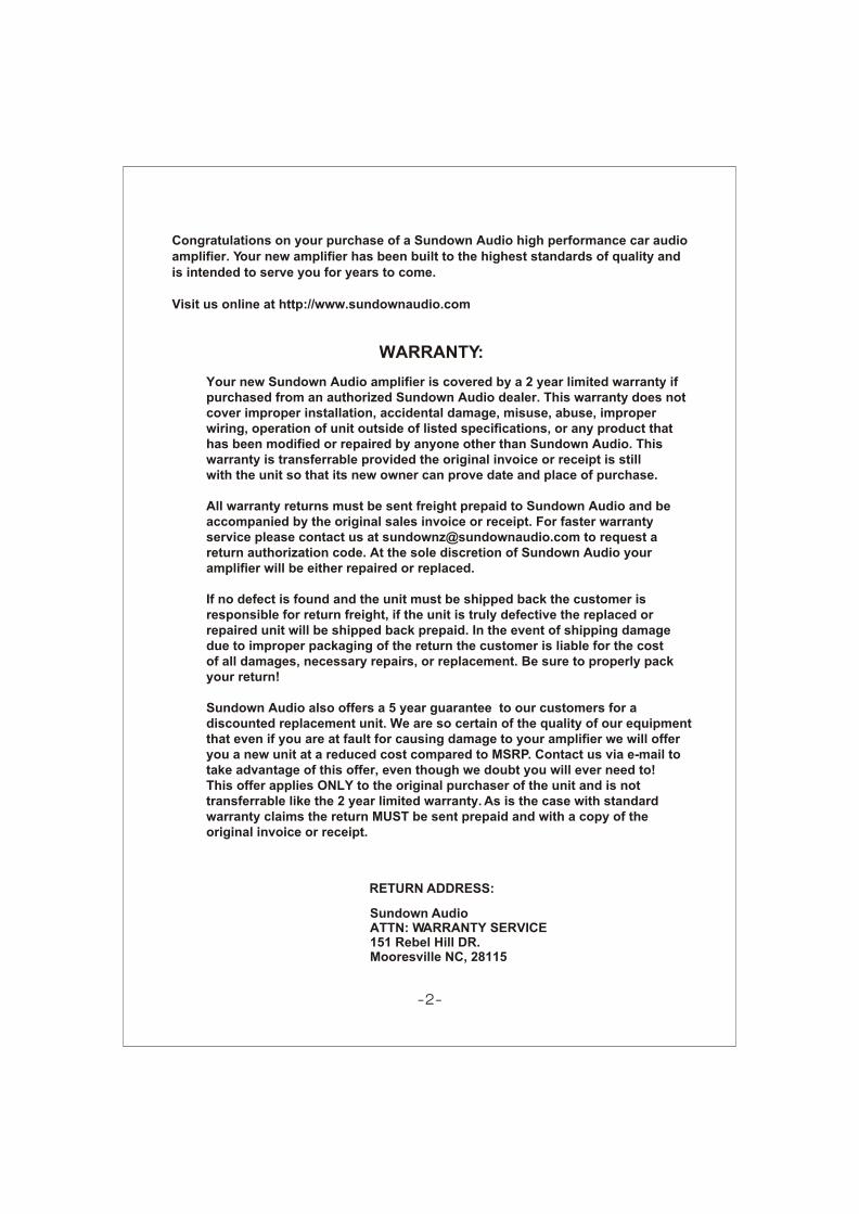
Congratulations on your purchase of a Sundown Audio high performance car audioamplifier. Your new amplifier has been built to the highest standards of quality andis intended to serve you for years to come.
Visit us online at http://www.sundownaudio.com
WARRANTY:
Your new Sundown Audio amplifier is covered by a 2 year limited warranty ifpurchased from an authorized Sundown Audio dealer. This warranty does notcover improper installation, accidental damage, misuse, abuse, improperwiring, operation of unit outside of listed specifications, or any product thathas been modified or repaired by anyone other than Sundown Audio. Thiswarranty is transferrable provided the original invoice or receipt is stillwith the unit so that its new owner can prove date and place of purchase.
All warranty returns must be sent freight prepaid to Sundown Audio and beaccompanied by the original sales invoice or receipt. For faster warrantyservice please contact us at [email protected] to request areturn authorization code. At the sole discretion of Sundown Audio youramplifier will be either repaired or replaced.
If no defect is found and the unit must be shipped back the customer isresponsible for return freight, if the unit is truly defective the replaced orrepaired unit will be shipped back prepaid. In the event of shipping damagedue to improper packaging of the return the customer is liable for the costof all damages, necessary repairs, or replacement. Be sure to properly packyour return!
Sundown Audio also offers a 5 year guarantee to our customers for a discounted replacement unit. We are so certain of the quality of our equipment that even if you are at fault for causing damage to your amplifier we will offer you a new unit at a reduced cost compared to MSRP. Contact us via e-mail totake advantage of this offer, even though we doubt you will ever need to!This offer applies ONLY to the original purchaser of the unit and is nottransferrable like the 2 year limited warranty. As is the case with standardwarranty claims the return MUST be sent prepaid and with a copy of theoriginal invoice or receipt.
RETURN ADDRESS:
Sundown AudioATTN: WARRANTY SERVICE151 Rebel Hill DR.Mooresville NC, 28115

Features
-3-
SAX-125.2
SAX-50.4
SAX-100.4
4/3/2 Channel Bridgeable Class-AB AmplifierMOSFET PWM Power SupplyStable Into 4 Ohms Bridged or 2 Ohms Stereo LoadVariable Subsonic FilterIndependent 1/2 and 3/4 Channel High Pass Filter Variable with x 10 Range Selectable SwitchIndependent 1/2 and 3/4 Channel Low Pass Filter Variable with x 10 Range Selectable SwitchHPF/FULL/LPF Selectable SwitchIndependent 1/2 and 3/4 Channel Electronic Crossover Slope Selectable Switch with 12dB and 24dB OctaveVariable Input Level ControlInput Sensitivity : 200mV ~ 6VSubsonic Filter : 10Hz ~ 500HzSignal Input and Line Out RCA ConnectorsMulti-Way Protection circuitry (Thermal/Over Current/Speaker Short/Speaker DC protection)
Tested Voltage & THD: 14.4V & Less than 0.05% THDOperating Voltage : DC10V~16V Power InputWired Remote Controller
2/1 Channel Bridgeable Class-AB AmplifierMOSFET PWM Power SupplyStable Into 4 Ohms Bridged or 2 Ohms Stereo Load12dB Octave Electronic Crossover SlopeVariable Subsonic FilterHigh Pass Filter Variable with x 10 Range Selectable SwitchLow Pass Filter Variable with x 10 Range Selectable SwitchHPF/FULL/LPF Selectable SwitchVariable Bass Boost ControlVariable Bass-Boost Frequency ControlVariable Input Level ControlInput Sensitivity : 200mV ~ 6VSubsonic Filter : 10Hz ~ 500HzSignal Input and Line Out RCA ConnectorsMulti-Way Protection circuitry (Thermal/Over Current/Speaker Short/Speaker DC protection)
Tested Voltage & THD: 14.4V & Less than 0.05% THDOperating Voltage : DC10V~16V Power InputWired Remote Controller
4/3/2 Channel Bridgeable Class-AB AmplifierMOSFET PWM Power SupplyStable Into 4 Ohms Bridged or 2 Ohms Stereo Load12dB Octave Electronic Crossover SlopeVariable Subsonic FilterIndependent 1/2 Channel High Pass Filter Variable with x 10 Range Selectable Switch
Variable 1/2 Channel Low Pass Filter with HPF/FULL/LPF Selectable Switch
Independent 3/4 Channel Low Pass Filter Variable with x 10 Range Selectable Switch
Variable 3/4 Channel High Pass Filter with HPF/FULL/LPF Selectable Switch
Independent 1/2 and 3/4 Channel Bass Boost Variable ControlVariable Bass-Boost Frequency ControlVariable Input Level ControlInput Sensitivity : 200mV ~ 6VSubsonic Filter : 10Hz ~ 500HzSignal Input and Line Out RCA ConnectorsMulti-Way Protection circuitry (Thermal/Over Current/Speaker Short/Speaker DC protection)
Tested Voltage & THD: 14.4V & Less than 0.05% THDOperating Voltage : DC10V~16V Power InputWired Remote Controller

Specifications
50W x 4CH80W x 4CH160W x 2CH>90dB 50Hz~500Hz (CH1&2) 50Hz~5KHz (CH3&4) 50Hz~5KHz (CH1&2)50Hz~500Hz (CH3&4)10Hz to 500Hz 0~18dB35Hz to 120Hz 10Hz ~ 40KHz (+/-1dB)
75dB 25A x 2Variable 200mV~6V (+/- 5%) 252(W) x 58(H) x 310(L)mm
<0.1%
Rated power output -RMS Watt @ 4 Ohms ----------------------------- -RMS Watt @ 2 Ohms ----------------------------- -Bridged Power @ 4 Ohms -----------------------Signal to Noise Ratio -----------------------------------Low Pass Crossover ----------------------------------- ------------------------------------High Pass Crossover ----------------------------------- -----------------------------------
--------------------------------Bass Boost -------------------------------------------------
--------Frequency Response -----------------------------------THD@RMS Watts ----------------------------------------Channel Separation --------------------------------------Fuse Rating -------------------------------------------------Input Sensitivity -------------------------------------------Dimensions -------------------------------------------------
Variable Subsonic Filter
Variable Bass-Boost Frequency Control
-4-
SAX-125.2
SAX-50.4
SAX-100.4
Rated power output -RMS power, 4 ohm stereo ----------------------- -RMS power, 2 ohm stereo ---------------------- -RMS power, 4 ohm bridged ---------------------Signal to Noise Ratio -----------------------------------Low Pass Crossover -----------------------------------High Pass Crossover -----------------------------------
--------------------------------Bass Boost -------------------------------------------------
--------Frequency Response ------------------------------------THD@RMS Watts -----------------------------------------Channel Separation --------------------------------------Fuse Rating -------------------------------------------------Input Sensitivity -------------------------------------------Dimensions --------------------------------------------------
Variable Subsonic Filter
Variable Bass-Boost Frequency Control
125W x 2CH200W x 2CH400W x 1CH>90dB50Hz ~ 5KHz30Hz ~ 3KHz10Hz to 500Hz 0~18dB35Hz to 120Hz 10Hz ~ 40KHz (+/-1dB) <0.1% 75dB 20A x 3Variable 200mV~6V (+/- 5%)252(W) x 58(H) x 340(L)mm
Rated power output -RMS power, 4 ohm stereo ----------------------- -RMS power, 2 ohm stereo ---------------------- -RMS power, 4 ohm bridged ---------------------Signal to Noise Ratio -----------------------------------Low Pass Crossover -----------------------------------High Pass Crossover -----------------------------------
--------------------------------Frequency Response ------------------------------------THD@RMS Watts ----------------------------------------Channel Separation --------------------------------------Fuse Rating -------------------------------------------------Input Sensitivity -------------------------------------------Dimensions --------------------------------------------------
Variable Subsonic Filter
100W x 4CH160W x 4CH320W x 2CH>90dB50Hz ~ 5KHz50Hz ~ 5KHz10Hz to 500Hz 10Hz ~ 40KHz (+/-1dB) <0.1% 75dB 30A x 3Variable 200mV~6V (+/- 5%)252(W) x 58(H) x 480(L)mm
BASS REMOTE
HPF
FREQ.
LPF CH1
CH2
PROTECTION
LINE OUTPOWER
1KHz50Hz
18dB0dB250Hz30Hz 120Hz35Hz
BASS BOOST
120Hz35Hz
BASS BOOST
18dB0dB
Q0.2V6V 100Hz10Hz 500Hz50Hz
x1 x10
x1 x10
SUBSONICGAIN
GAIN SUBSONIC
CH1 CH3
SIGNAL INPUT
CH2 CH4
0.2V6V 100Hz10Hz
HPF
500Hz50Hz
LPF
RANGE
RANGE HPFFULL
LPF
LPFFULL
HPF
Channel 3/4Channel 1/2
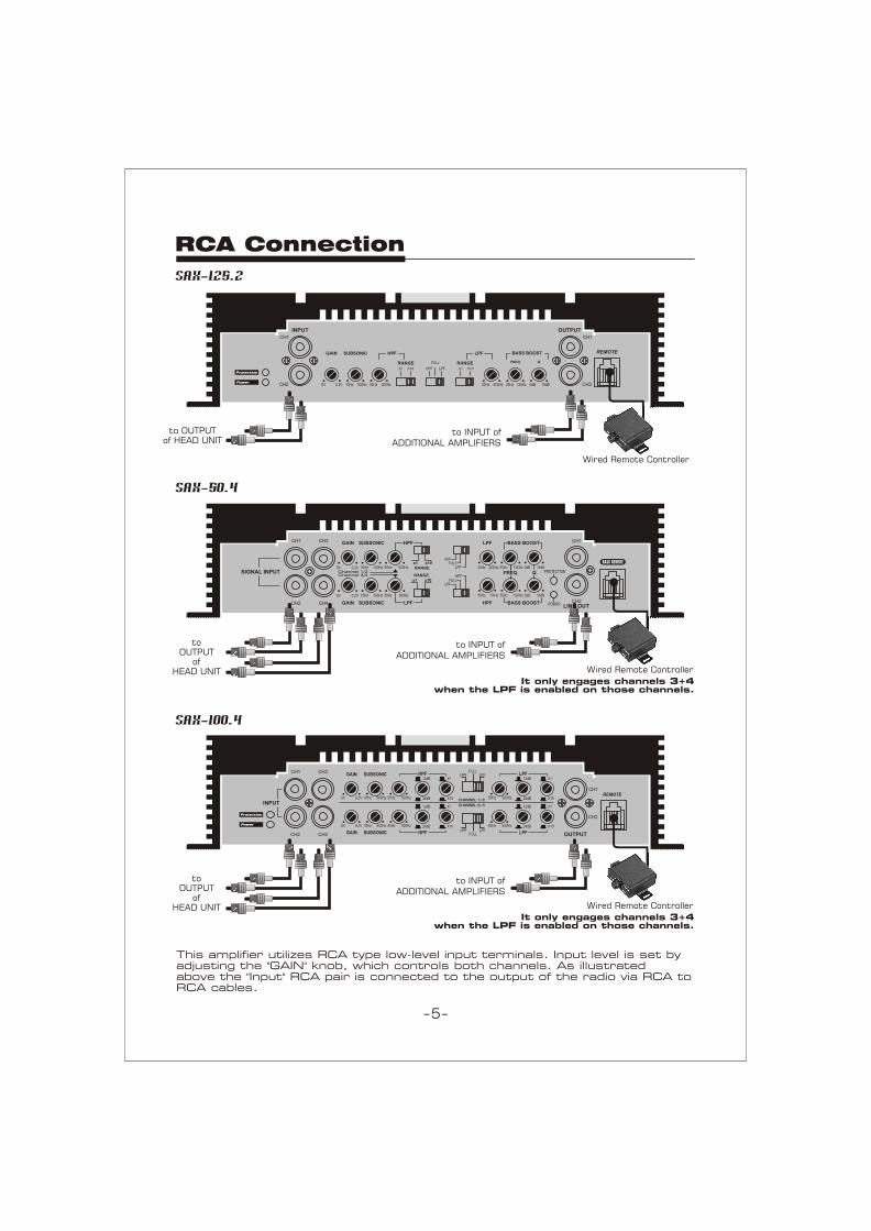
to INPUT of ADDITIONAL AMPLIFIERS
to OUTPUT
of HEAD UNIT
RCA Connection
This amplifier utilizes RCA type low-level input terminals. Input level is set by adjusting the "GAIN" knob, which controls both channels. As illustrated above the "Input" RCA pair is connected to the output of the radio via RCA to RCA cables.
Wired Remote Controller
-5-
It only engages channels 3+4 when the LPF is enabled on those channels.
SAX-125.2
SAX-50.4
SAX-100.4
GAIN
Protection
Power
SUBSONIC HPF
RANGEX1 X10
FULL
LPFHPF
REMOTEBASS BOOSTLPF
RANGEX1 X10
FREQ. Q.
INPUTCH1
CH2 0.2V6V 500Hz10Hz 300Hz30Hz 500Hz50Hz 120Hz35Hz 18dB0dB
CH1
CH2
OUTPUT
INPUT
CH1 CH3
CH2 CH4
GAIN
0.2V6V 500Hz10Hz
SUBSONIC
500Hz50Hz
HPF12dB
24dB
X1
X10
CHANNEL 3/4
CHANNEL 1/2
0.2V6V 500Hz10Hz 500Hz50Hz
12dB
24dB
X1
X10
HPFFULL
LPF
CH1
CH2
REMOTE
OUTPUT
500Hz50Hz
LPF12dB
24dB
X1
X10
500Hz50Hz
12dB
24dB
X1
X10
LPF
Protection
Power
HPFFULL
LPFHPFGAIN SUBSONIC
to OUTPUTof HEAD UNIT
to INPUT of ADDITIONAL AMPLIFIERS
Wired Remote Controller
to INPUT of ADDITIONAL AMPLIFIERS
to OUTPUT
of HEAD UNIT Wired Remote Controller
It only engages channels 3+4 when the LPF is enabled on those channels.
BRIDGE
Left/Ch1
Left/Ch3 Right/Ch4
Right/Ch2
POWERFUSE
SPEAKER
B+ REM GND
FUSEPOWER SPEAKER
Left
BRIDGEB+REMGND
Right
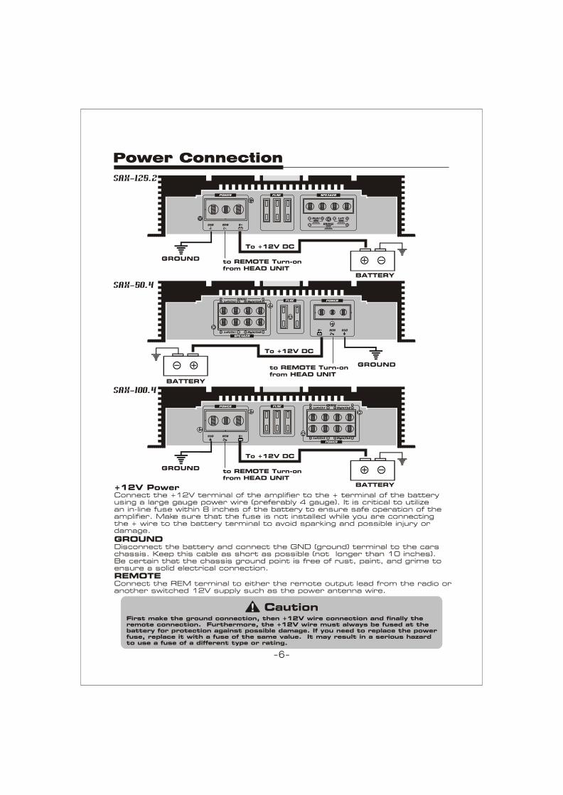
Power Connection
First make the ground connection, then +12V wire connection and finally the remote connection. Furthermore, the +12V wire must always be fused at the battery for protection against possible damage. If you need to replace the power fuse, replace it with a fuse of the same value. It may result in a serious hazard to use a fuse of a different type or rating.
Caution
BATTERY
to REMOTE Turn-onfrom HEAD UNIT
GROUND
To +12V DC
REMOTEConnect the REM terminal to either the remote output lead from the radio or another switched 12V supply such as the power antenna wire.
+12V PowerConnect the +12V terminal of the amplifier to the + terminal of the battery using a large gauge power wire (preferably 4 gauge). It is critical to utilize an in-line fuse within 8 inches of the battery to ensure safe operation of the amplifier. Make sure that the fuse is not installed while you are connecting the + wire to the battery terminal to avoid sparking and possible injury or damage.
GROUNDDisconnect the battery and connect the GND (ground) terminal to the cars chassis. Keep this cable as short as possible (not longer than 10 inches). Be certain that the chassis ground point is free of rust, paint, and grime to ensure a solid electrical connection.
SAX-125.2
SAX-50.4
SAX-100.4
BATTERY
to REMOTE Turn-onfrom HEAD UNIT
GROUND
To +12V DC
POWER
B+REMGND
FUSE
POWER
BRIDGERight/Ch2Left/Ch1
Right/Ch4Left/Ch3
-6-
BATTERY
to REMOTE Turn-onfrom HEAD UNIT
GROUND
To +12V DC
FUSE SPEAKER
Left
BRIDGE
Right
FUSE SPEAKER
Left
BRIDGE
Right
FUSE SPEAKER
Left
BRIDGE
Right
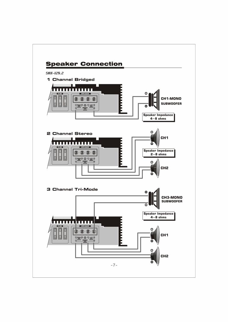
Speaker Connection
SAX-125.2
1 Channel Bridged
2 Channel Stereo
3 Channel Tri-Mode
SUBWOOFER
CH1-MONO
Speaker Impedance4~8 ohms
CH3-MONO
CH2
CH1
Speaker Impedance4~8 ohms
CH2
CH1
SUBWOOFER
Speaker Impedance2~8 ohms
-7-

BRIDGE
Left/Ch1
Left/Ch3 Right/Ch4
Right/Ch2
FUSE
SPEAKER
BRIDGE
Left/Ch1
Left/Ch3 Right/Ch4
Right/Ch2
FUSE
SPEAKER
BRIDGE
Left/Ch1
Left/Ch3 Right/Ch4
Right/Ch2
FUSE
SPEAKER
2 Channel Bridged
CH3
CH1-MONOSUBWOOFER
CH2-MONOSUBWOOFER
4 Channel Stereo
CH4
CH2
CH1
6 Channel Tri Mode
CH4
CH2CH1
Speaker Impedance4~8 ohms
Speaker Impedance2~8 ohms
Speaker Impedance4~8 ohms
CH6-MONOSUBWOOFER
CH5-MONOSUBWOOFER
CH3
Speaker Connection
-8-
SAX-50.4

FUSE
POWER
BRIDGERight/Ch2Left/Ch1
Right/Ch4Left/Ch3
FUSE
POWER
BRIDGERight/Ch2Left/Ch1
Right/Ch4Left/Ch3
FUSE
POWER
BRIDGERight/Ch2Left/Ch1
Right/Ch4Left/Ch3
2 Channel Bridged
CH3
CH1-MONOSUBWOOFER
CH2-MONOSUBWOOFER
4 Channel Stereo
CH4
CH2
CH1
6 Channel Tri Mode
CH4
CH2CH1
Speaker Impedance4~8 ohms
Speaker Impedance2~8 ohms
Speaker Impedance4~8 ohms
CH6-MONOSUBWOOFER
CH5-MONOSUBWOOFER
CH3
Speaker Connection
-9-
SAX-100.4
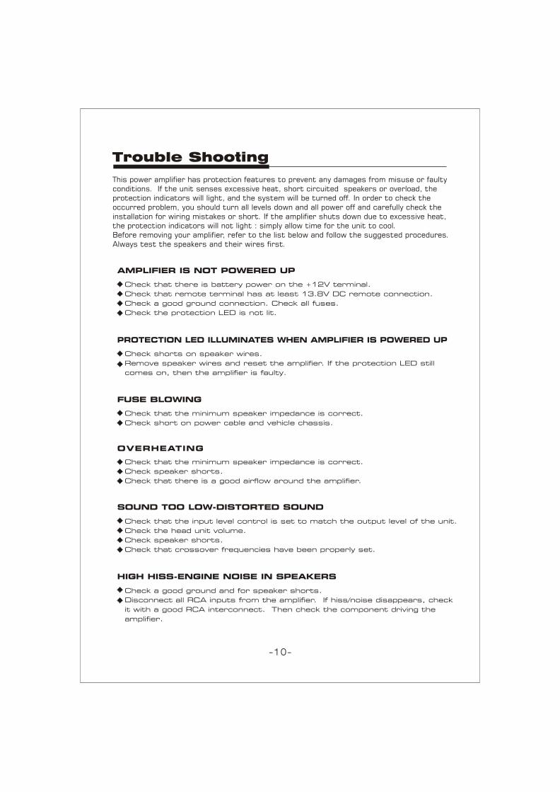
This power amplifier has protection features to prevent any damages from misuse or faulty conditions. If the unit senses excessive heat, short circuited speakers or overload, the protection indicators will light, and the system will be turned off. In order to check the occurred problem, you should turn all levels down and all power off and carefully check the installation for wiring mistakes or short. If the amplifier shuts down due to excessive heat, the protection indicators will not light : simply allow time for the unit to cool.Before removing your amplifier, refer to the list below and follow the suggested procedures. Always test the speakers and their wires first.
PROTECTION LED ILLUMINATES WHEN AMPLIFIER IS POWERED UP
FUSE BLOWING
OVERHEATING
Check that the minimum speaker impedance is correct.
Check speaker shorts.
Check that there is a good airflow around the amplifier.
Check a good ground and for speaker shorts.
Disconnect all RCA inputs from the amplifier. If hiss/noise disappears, check
it with a good RCA interconnect. Then check the component driving the
amplifier.
SOUND TOO LOW-DISTORTED SOUND
Check that the input level control is set to match the output level of the unit.
Check the head unit volume.
Check speaker shorts.
Check that crossover frequencies have been properly set.
HIGH HISS-ENGINE NOISE IN SPEAKERS
Check that the minimum speaker impedance is correct.
Check short on power cable and vehicle chassis.
AMPLIFIER IS NOT POWERED UP
Check that there is battery power on the +12V terminal.
Check that remote terminal has at least 13.8V DC remote connection.
Check a good ground connection. Check all fuses.
Check the protection LED is not lit.
Check shorts on speaker wires.
Remove speaker wires and reset the amplifier. If the protection LED still
comes on, then the amplifier is faulty.
Trouble Shooting
-10-

-11-

MADE IN KOREA