Embed Size (px)
Citation preview

Owner’s Manual & Technical Information
HLNS1200
2
LegalEntire contents ©2016 Helion RC
Before using your product, review all documentation and inspect the product carefully. If for some reason you decide it is not what you wanted, then do not continue with unpacking, setup or operation of your product. Your local hobby dealer cannot accept a product for return or exchange after partaking in actions that produce wear and tear.
Read, understand and follow all instructions and accompanying material carefully before operating or assembling your product to prevent serious damage. Failure to complete these tasks properly or intentional aversion to the content will be considered abuse and/or neglect.
Product specifications are subject to change without notice. Due to ongoing development, the actual product may vary from images shown.
This product contains chemicals known to the State of California to cause cancer, birth defects and other reproductive harm.
This product is not a toy! (14+) Recommended for ages 14 and up. Adult supervision required for ages under 18 years old. Contains small parts, keep out of reach of children 3 years of age and younger.
Important InformationThroughout this manual you will see different notes, cautions and warnings to help alert you to important information about the section you are reading. Please see below for the descriptions and what to look for to identify each type.
WARNING: THIS INFORMATION IS IMPERATIVE FOR YOU TO UNDERSTAND AND FOLLOW AS LACK OF COMPLIANCE WITH THE CONTENTS OF THE WARNING COULD CAUSE PERSONAL INJURY OR PROPERTY DAMAGE.
CAUTION: THIS INFORMATION IS IMPORTANT FOR YOU TO UNDERSTAND AND FOLLOW AS LACK OF COMPLIANCE WITH THE CONTENTS OF THE CAUTION COULD CAUSE DAMAGE TO YOUR PRODUCT THAT IS NOT COVERED UNDER WARRANTY.
Note/Tip: This information is important for you to keep in mind, most commonly used to recall previously given information or to direct you to or provide you with additional information on a subject.

3
Contents
Notice .......................................................................................... 4
Precautions................................................................................. 4
Package Contents ...................................................................... 5
Items Needed to Complete ........................................................ 5
Introduction ................................................................................ 6
Features ...................................................................................... 6
Getting Started ........................................................................... 7
Ikonnik ET4 Radio Sysytem ...................................................... 8
Radient Reaktor120T Overview ................................................ 9
Adjusting and Tuning Your Vehicle ..........................................18
General Care & Maintenance ..................................................19
Storage and Disposal ..............................................................19
Troubleshooting Problems .......................................................23
Appendix A: Troubleshooting for Reaktor Power System .......25
Appendix B: Troubleshooting Guide ........................................26
Appendix C: Differential Exploded Views ................................27
Appendix D: Shock Exploded Views ........................................28
Appendix F: Front Suspension Exploded View ........................29
Appendix H: Rear Suspension Exploded View ........................30
Appendix I: Main Chassis Exploded View ...............................31
Appendix J: Spare Parts List ....................................................32
Warranties ................................................................................35
Declaration of Conformity ........................................................ 37

4
NoticeYour product is calibrated and tested at the factory prior to final packaging, some issues may arise during shipping and handling that can be easily resolved at home. For other adjustments it should be known that hobby grade radio controlled products such as this differ from toy grade, in that they are intended to be user-serviceable products where the user can program, disassemble and maintain their own product. We try our best to ensure the information you need to introduce you to this form of product ownership is available to you though this manual. Please see the troubleshooting guide at the back of this manual for assistance in resolving issues, either as they are experienced out of the box or as found after regular use.
Note: Assuming your product functions properly as intended out of the box, the best thing you can do is pay close attention to how it feels, sounds and functions. This will help you identify problems later since you will have a reference of how the product is supposed to perform.
If you require further information or assistance resolving a possible issue, please consult the warranty card included with your product.
PrecautionsAlthough great for first time users, Helion RC products are indeed advanced radio controlled vehicles with sensitive electronics and moving parts capable of causing injury if used improperly. Always use caution and common sense as failure to operate your product in a safe and responsible manner can result in damage to the product or other properties. Therefore this product is not intended for use or maintenance by children without direct adult supervision. Helion RC and your hobby dealer shall not be liable for any loss or damages, whether direct, indirect, special, incidental, or consequential, arising from the use, misuse, or abuse of this product or any product required to operate or maintain it.
WARNING: ALWAYS KEEP LOOSE CLOTHING, HAIR, TOOLS OR OTHER MOVABLE OBJECTS AWAY FROM MOVING PARTS OF YOUR VEHICLE DURING SETUP AND CONFIGURATION. SPINNING TIRES CAN EXPAND AND MAKE CONTACT WITH SMALL TOOLS, OR HARDWARE AND SEND THEM FLYING AT HIGH SPEEDS RISKING INJURY TO YOU OR OTHERS AROUND YOU.
• Your model can cause serious damage or injury so please use caution and courtesy when operating your model.
• As a safety precaution, perform all transmitter and receiver adjustments with all parts of the vehicle off the ground. This ensures the complete control over the vehicle at all times during adjustments.
• Do not operate your model near traffic, bystanders, parking areas, or any other area that could result in injury to people or damage to property.
• If at any time during the operation of your model you observe any erratic or abnormal behavior of your model, immediately stop operation and bring the mode to a safe stop in a safe location to diagnose the problem.
• Always power on your transmitter before turning your vehicle on.
5
• If you have little or no experience operating R/C models, we strongly recommend you seek the assistance of your local hobby dealer.
• Do not expose the transmitter to water or excessive moisture.
• Do not operate radio controlled products in a lightning or thunder storm.
• Ensure your batteries (both Tx and vehicle) are charged before each use.
• Check all servos and electrical connections prior to each use.
• Use caution when handling your vehicle after use as electronics may get HOT and could cause a burn if handled carelessly.
• Always allow the motor in your vehicle to cool completely before using it again.
R/C models are an extremely fun hobby, but safety should never be ignored or taken lightly. Always take caution when operating your model as damage to property and injury can result from careless operation. Please consult your local hobby dealer with any questions or troubleshooting issues. And of course don’t forget to have fun, you deserve it after reading through all of these safety tips!
Package Contents• 1 x Four 10TR Truggy
• 1 x IKONNIK ET4 Xenon 2.4GHz 4-channel transmitter with grips
• 1 x 1.5mm hex wrench
• 1 x 2.0mm hex wrench
• 1 x 2.5mm hex wrench
• 1 x Quick-start guide with decals
Items Needed to Complete and Enjoy• 1 x 2S, 3S or 4S Li-Po battery
• 1 x Suitable Li-Po battery charger (Radient Ascend 6A multi-chem AC charger - RDNA0044)
• 4 x AA alkaline batteries for the transmitter

6
IntroductionSelect by Helion was born of a quest for the ultimate marriage of performance, value and innovation. Making any sort of compromise in this respect is not an easy task, so we’ve done our best not to. We’ve included what we believe to be the best radio system in its class, the most durable and robust brushless powerplant that includes proprietary technology, and we’ve added high performance engineering grade composite plastics with aircraft grade aluminum and high carbon steel components. We’ve taken a chassis platform that could have been ok, and we’ve made it great. The individual components can be seen as capable, over engineered, refined and optimized, but their specs weren’t chosen on how they perform in isolation. It was their collective performance that mattered so we made sure the components complemented each other to achieve perfect synergy in a product that best fits our customers’ needs and expectations. It’s not just about being good, it’s about being Select.
Features• Radient Reaktor 120-4T LiPo-ready brushless all-
weather sensorless ESC with TSP
• 2850kV sensorless 4-pole 3668 size brushless motor
• IKONNIK ET4 2.4GHz 4-channel radio system with 10 model memory and beginner mode.
• All-weather 6kg high torque servo
• Four wheel independent suspension
• Robust shaft based 4 wheel drive with center differential
• All metal gear transmission with rugged planetary HD differentials
• Included adjustable wheelie bar
• Rubber sealed ball bearings throughout
• Adjustable, oil filled, threaded aluminum body, coil-over shock absorbers
• Dual bell crank ball bearing steering with adjustable servo saver
• Durable, rugged, engineering grade composite chassis components
• Pre-installed LED head and tail lights
• High-grip long-wear tires with realistic off-road style wheels
• Aluminum bulkheads, steering spindles, suspension pivots and wheel hexes
• Chassis guard / net
• 2 - 4S LiPo ready (battery not included)
• 1:8 style wing with adjustable mounting
• Versatile and adjustable battery straps

7
Getting StartedBelow are some steps to help get you going right away and most applicable to those who have used RC products before. If you are new to the hobby or it has been a while since you’ve worked with the latest technology, please read through the manual to acquaint yourself with the latest procedures, Warnings, Cautions and Tips.
ChargingAlthough this information should be included with your batteries and charger, we have included it here again to ensure you have seen it and are aware of the most common things to be aware of with regards to charging our batteries.
• Never leave the battery unattended while charging and never operate the charger without adult supervision.
• Never charge a warm battery, always allow the battery to cool to room temperature before charging.
• Always use a fire-proof charge bag when charging/discharging LiPo batteries
• Never drop the charger or battery and do not attempt to charge a damaged battery.
• Inspect the battery and charger before use. Never use a battery or charger if the wire or connector has been damaged or if the battery has experienced a short.
• Incorrect use of the battery, connections, or charging equipment can cause personal injury or property damage.
• Never allow batteries or charger to come in contact with moisture at any time.
• Stop charging immediately if the battery or charger becomes hot or changes form during use.
WARNING: WHEN USING LIPO BATTERIES, ONLY USE CHARGERS DESIGNED FOR USE WITH LIPO BATTERIES FOR THE RC INDUSTRY THAT ENABLE BALANCE CHARGING AND USE THE SUPPLIED CONNECTOR. USE OF OTHER (NON-RC SPECIFIC) CHARGERS OR CONNECTORS CAN CAUSE CATASTROPHIC FALURES AND CAUSE PERMANENTLY DAMAGE YOUR BATTERY AND/OR CONNECTED EQUIPMENT. THIS PRODUCT IS NOT A TOY AND SHOULD NOT BE CHARGED, OPERATED, OR MAINTAINED WITHOUT SUPERVISION OF AN ADULT.
Fully balance charge your chosen 2S, 3S or 4S LiPo battery in accordance with charging and safety guidelines supplied with the battery. LiPo batteries are sensitive to the charge current and as such, it should be chosen with care.
• The battery pack must have a compatible HCT plug, or use an adapter that includes high current connectors.
• You can use a suitable NiMH battery pack, however you must change the LVC (low voltage cut-off) on the ESC (see Appendix at the back of this manual for ESC settings)

8
Preparing to Drive1. Remove the body from vehicle.
2. Locate the wheelie bar and secure it.
3. Locate the spoiler and secure it.
4. Loosen the hook-and-loop battery straps.
5. Install the fully charged battery into the vehicle, be sure to secure the battery straps to keep the battery in.
Note/Tip: If you are you using a tall high capacity battery, optional long straps are available to suit your configuration - HLNS1104.
6. Ensure the motor is plugged into the ESC.
7. Ensure the vehicle power switch is in the OFF position and connect the battery to the ESC.
8. Read and understand the manual supplied with the Ikonnik ET4 radio system.
CAUTION: NOTE TRANSMITTER CAUTIONS AND SETTING INSTRUCTIONS BEFORE USE.
9. Install the [4] AA type alkaline batteries into the transmitter.
10. Confirm settings for steering/throttle trim and motor direction (update connection if necessary)
11. Confirm ESC settings for the battery you will use (check LVC program mode and ensure it is properly set to 5 if using a LiPo or 1 if you are using a NiMH battery pack.)
12. Re-install body with 4 supplied clips; turn your equipment ON (transmitter first!) and enjoy!
The IKONNIK ET4 Radio SystemYour Select Four 10TR comes equipped with one of the most advanced 2.4GHz radios in its class. It is feature packed and incorporates technology normally reserved for only the upper echelon of radio systems and some completely unique to IKONNIK.
Familiarize yourself with the usage and features presented in the IKONNIK ET4 Owner’s Manual and quick start guide to enhance your experience:
Most importantly we recommend you become familiar with the following features of the system.
• Pairing the transmitter and receiver.
• Setting Steering and Throttle trims.
• Using the 10 Model memory.
• Utilizing the Beginner Modes to share and enhance the fun.
• Configuring the ergonomics to fit you.

9
Radient Reaktor120T Brushless System OverviewThe Radient Reaktor series brushless motor and ESC is a great power plant to satisfy your need for speed and performance, not just an entry level brushless system, your Reaktor system has some of the most advanced technology in ESC and motor development in the industry today. Here are some great features we included that help keep your system running in top shape ensuring maximum enjoyment potential.
CAUTION: ALWAYS ALLOW YOUR MOTOR TO COOL BETWEEN RUNS. EXCESSIVE ACCELERATION AND AGGRESSIVE DRIVING WILL CAUSE YOUR SYSTEM TO GET HOT. EXCERCISE GREAT CARE WHEN HANDLING YOUR VEHICLE AFTER RUNNING TO AVOID GETTING BURNED.
Some Great Features of your ESC• Total System Protection (TSP) is an exclusive technology which protects
your entire system against typical failures experienced and sometimes caused by new users.
CAUTION: ALTHOUGH TSP HAS BEEN ENGINEERED TO PROVIDE THE MAXIMUM PROTECTION AVAILABLE TODAY, IT IN NO WAY MAKES FAILING PRODUCT IMPOSSIBLE. TSP PROVIDES ADDED PROTECTION AGAINST THE MOST COMMON TYPES OF FAILURES EXPERIENCED AND SOMETIMES INDUCED BY NEW USERS.
• Ready for all weather conditions allowing you to experience the fun of rain, puddles and snow.
CAUTION: REMOVE THE COOLING FAN WHEN RUNNING IN WATER TO PREVENT FAN OVERLOAD AND FAILURE. AFTER RUNNING, CLEAN AND THEN DRY THE ESC AND FAN TO AVOID OXIDATION OF THE COPPER CONNECTORS.
• Specially designed for RC car and truck, with excellent start-up, acceleration and linearity features.
• Compatible with sensorless brushless motors.
• 2 running modes suitable for different applications (“Forward with brake” mode, “Forward/Backward with brake” mode).
• Proportional ABS brake function with 4 steps of maximum brake force adjustment, 8 steps of drag-brake force adjustment.
• 4 start modes (“Punch”) from “Soft” to “Very aggressive” to be suitable for different chassis, tires and tracks.
• Multiple protection features: Low voltage cut-off protection for LiPo or NiMH battery / Over-heat protection / Throttle signal loss protection / Motor blocked protection.
• Easily programmed with the “SET” button on the ESC.
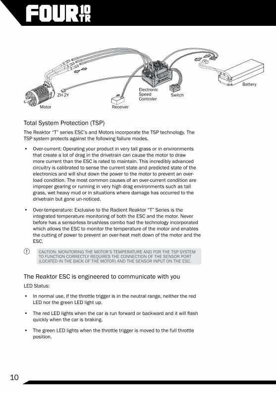
Your ESC has been pre-installed at the factory but before using your vehicle each time it is good to double check the wiring for damage or loose connections to ensure everything is in working order before use. Refer to the diagram below to check the connections of your electronics system. Some brushless motors such as the Reaktor included with your vehicle use only black wires, this is okay. On sensorless brushless systems the motor will change operating direction when any two of the motor wires are swapped.
10
Total System Protection (TSP)The Reaktor “T” series ESC’s and Motors incorporate the TSP technology. The TSP system protects against the following failure modes.
• Over-current: Operating your product in very tall grass or in environments that create a lot of drag in the drivetrain can cause the motor to draw more current than the ESC is rated to maintain. This incredibly advanced circuitry is calibrated to sense the current state and predicted state of the electronics and will shut down the power to the motor to prevent an over-load condition. The most common causes of an over-current condition are improper gearing or running in very high drag environments such as tall grass, wet heavy mud or in situations where damage has occurred to the drivetrain but gone un-noticed.
• Over-temperature: Exclusive to the Radient Reaktor “T” Series is the integrated temperature monitoring of both the ESC and the motor. Never before has a sensorless brushless combo had the technology incorporated which allows the ESC to monitor the temperature of the motor and enables the cutting of power to prevent an over-heat melt down of the motor and the ESC.
CAUTION: MONITORING THE MOTOR’S TEMPERATURE AND FOR THE TSP SYSTEM TO FUNCTION CORRECTLY REQUIRES THE CONNECTION OF THE SENSOR PORT (LOCATED IN THE BACK OF THE MOTOR) AND THE SENSOR INPUT ON THE ESC.
The Reaktor ESC is engineered to communicate with youLED Status:
• In normal use, if the throttle trigger is in the neutral range, neither the red LED nor the green LED light up.
• The red LED lights when the car is run forward or backward and it will flash quickly when the car is braking.
• The green LED lights when the throttle trigger is moved to the full throttle position.
Battery
Switch
ReceiverMotor
ZH-2YElectronic Speed Controler

11
Alert Tones:
• Input voltage abnormal alert tone: The ESC begins to check the input voltage when power on, if it is out of the normal range, such an alert tone will be emitted: “beep-beep-, beep-beep-, beep-beep-” (There is 1 second time interval between every “beep-beep-” tone).
• Throttle signal abnormal alert tone: When the ESC can’t detect the normal throttle signal, such an alert tone will be emitted: “beep-, beep-, beep-” (There is 2 seconds time interval between every “beep-” tone).
Protection Functions:
• Low voltage cut-off protection: If the voltage of a LiPo battery pack is lower than the selected threshold for 2 seconds, the ESC will cut of the output power. Please note that the ESC cannot be restarted if the voltage of each LiPo cell is lower than the set threshold.
• Over-heat protection: When the temperature of the ESC is over 105 degrees Celsius for 5 seconds, the ESC will cut off the output power.
• Throttle signal loss protection: The ESC will cut off the output power if the throttle signal is lost for 0.2 second.
Throttle Range Calibration 1. Hold your transmitter approximately 1ft away while calibrating the ESC.
2. Turn Transmitter ON first (transmitter should ALWAYS be ON if the ESC is ON.
3. Ensure your Throttle channel (Ch. 2) on your transmitter is set to “Reverse”.
4. Adjust both Throttle and Reverse/Brake EPA settings to 100%.
5. With the ESC OFF, press and hold the Set button near the switch and turn the ESC ON to enter setup mode. Release the button as soon as the LED begins to flash.
6. Without touching the trigger, press the button to set the neutral position, the GREEN LED will flash 1 time.
7. Pull/hold full throttle, press the button again, release the trigger, the GREEN LED will flash 2 times.
8. Push/hold full brake/reverse, press the button again, the GREEN LED will flash 3 times. Release trigger.
9. Switch the ESC OFF and back ON to complete setup.
10. Check the ESC operation to ensure forward throttle is actually forward, if not, switch any two of the motor wires and re-check. Then repeat steps 3-8 if you experience odd behavior.

12
Programming your ESCThe Radient Reaktor is a programmable ESC. Although the default settings should work well for most users, these settings exist so that you can fine tune the performance of your ESC to your experience and components. Its various programmable parameters can be adjusted either by interfacing with the ESC directly (button presses and counting LED flashes), or via the optional Reaktor Program Box which includes a digital readout of the settings for easier interpretation and faster setup. There are 6 programmable parameters for your consideration, below are descriptions of each Item and following is the table and programming instructions for choosing your settings should you choose to change from the defaults (highlighted in BOLD text).
CAUTION:THE MOST IMPORTANT OF THESE SETTINGS IS THE LOW VOLTAGE CUT-OFF THRESHOLD (ITEM 3). PLEASE READ THE DESCRIPTION AND USAGE SCENARIOS BELOW TO BETTER UNDERSTAND HOW TO USE THIS FEATURE.
Running Mode
Option 1: Forward with Brake. It has forward and brake functions only and is usually a racing mode.
Option 2: Forward / Reverse with Brake. This mode can be used as for training and it has “Forward/ Reverse with Brake” mode. Radient adopted the “DOUBLE-CLICK” method, that is your vehicle only brakes on the 1st time
Press and hold the SET button
Press theON/OFFbutton
Release the SET button once the LED flashes.
Move the throttle trigger to the neutral position and press the SET button.
The Green LED flashes once and motor emits “Beep” tone.
Move the throttle trigger to the end position of forward and press the SET button.
The Green LED flashes twice and motor emits “Beep-Beep” tone.
Move the throttle trigger to the end position of backward and press the SET button.
The Green LED flashes three times and motor emits “Beep-Beep-Beep” tone.
13
you push the throttle trigger forward (brake) (1st push). The motor stops when you quickly release the throttle trigger and then re-push the trigger quickly (2nd push), only then the vehicle will reverse. The reverse function will not work if your car does not come to a complete stop.The vehicle only reverses after the motor stops. This method is for preventing vehicle from being accidentally reversed.
Lipo Cells
“Auto Calculation” is the default setting. If LiPo batteries are often used with the same cell count, we would strongly recommend setting this item manually to avoid the incorrect “calculation” (For instance, the ESC may take a not fully charged 3S LiPo as a fully charged 2S LiPo) which may cause the low-voltage cutoff protection to not function ideally
Cutoff Voltage
Sets the voltage at which the ESC lowers or removes power to the motor in order to either keep the battery at a safe minimum voltage (for LiPo batteries). The ESC monitors the battery voltage all the time, it will immediately reduce the power to 50% and cut off the output 10 seconds later when the voltage goes below the cutoff threshold. The RED LED will flash a short, single flash that repeats to indicate the low-voltage cutoff protection is activated. Please set the “Cutoff Voltage” to “Disabled” if you are using NiMH batteries.
1. Disabled: The ESC does not cut the power off due to low voltage. We do not recommend using this option when you use any LiPo battery as you will irreversibly damage the product. You need to select this option when you are using a NiMH pack.
2. Auto (Low): Low cutoff voltage, difficulty to get the LVC Protection activated, is applicable to batteries with poor discharge capability.
3. Auto (Intermediate): Medium cutoff voltage, prone to getting the LVC Protection activated, is applicable to batteries with ordinary discharge capability.
4. Auto (High):High cutoff voltage, very prone to getting the LVC Protection activated, is applicable to packs with great discharge capability.
WARNING: IF YOU SET THE CUTOFF VOLTAGE TO DISABLED WHEN YOU USE A LIPO PACK, THEN PLEASE PAY ATTENTION TO THE POWER CHANGE OF YOUR VEHICLE. IN GENERAL, THE BATTERY VOLTAGE GETS PRETTY LOW WHEN YOUR VEHICLE IS SEVERELY LOSING POWER, THEN YOU SHOULD STOP USING THAT PACK.
Thermal protection
The ESC will automatically cut off the output with the GREEN LED flashes when the temperature gets up to the value you’ve previously preset and activates the ESC Thermal Protection. The output will not resume until the temperature gets down.
Motor Thermal Protection
The GREEN LED flashes when the motor temperature reaches to the preset value. The output will not resume until the motor temperature gets down.

14
Note: this protection works only when the temperature monitoring cable on the ESC is plugged into the temperature monitoring port (marked with “TEMP”) at the bottom of the matching HOBBYWING motor. It will be void if you don’t plug the cable into the port or set the “Motor Thermal Protection” to “Disabled”.
Motor Rotation
Pull the throttle trigger with the motor shaft facing you, the motor spins counter clockwise. When this item is set to CCW; the motor spins clockwise. When it is set to CW. The (A/B/C) wiring order of motors from different manufacturers may vary, so do the direction of the motor rotations. You can adjust the “Motor Rotation” or swap any two (ESC-to-motor) wires if the motor runs in reverse.
BEC Voltage
1. 6.0V: It’s applicable to ordinary servos. Do not use this option with high voltage servos; otherwise your servos may not function normally due to insufficient voltage.
2. 7.4V: It’s applicable to high voltage servos. Do not use this option with ordinary servos; otherwise your servos may be burnt due to high voltage.
Brake Force
The ESC provides proportional braking function; the braking effect is decided by the position of the throttle trigger. It sets the percentage of available braking power when full brake is applied. Large amount will shorten the braking time but it may damage your pinion and spur. Please select the most suitable brake amount as per your car condition and your preference.
CAUTION: BE SURE TO CHECK YOUR MAXIMUM BRAKE SETTINGS BY DRIVING FROM FULL THROTTLE TO FULL HARD BRAKE IN AN OPEN AREA. IF THE REAR TIRES COME OFF THE GROUND CAUSING A FRONT FLIP, THE VEHICLE WILL TUMBLE OUT OF CONTROL AND COULD CAUSE PERSONAL OR PROPERTY DAMAGE.
1. 12.5%: This is the lowest setting and should only be used when driving with slow motors and on loose (low traction) surfaces.
2. 25%
3. 37.5%
4. 50%: It is not recommended to go below this setting on asphalt surfaces as the stopping power may not be enough to safely slow your vehicle.
5. 62.5%
6. 75%: This is the default setting we feel will provide you the best starting point for many different levels of traction on various surfaces. Remember it is extremely important to only drive a vehicle as fast as you can safely stop it. If the vehicle hits something or someone it can cause serious injury.
7. 87.5%
8. 100%: This setting is only recommended if you are running a slotted type motor, running this with a slotless style motor combined with a 4wd vehicle will likely cause front flips thus a loss of control of your vehicle.
15
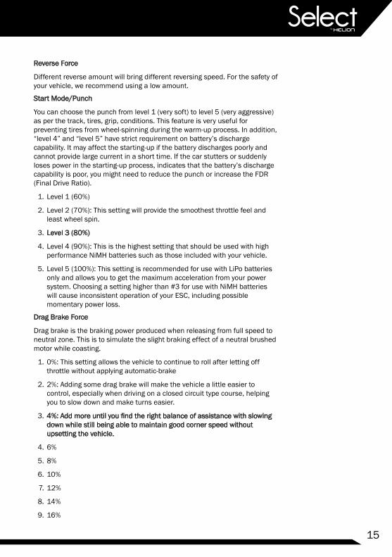
Reverse Force
Different reverse amount will bring different reversing speed. For the safety of your vehicle, we recommend using a low amount.
Start Mode/Punch
You can choose the punch from level 1 (very soft) to level 5 (very aggressive) as per the track, tires, grip, conditions. This feature is very useful for preventing tires from wheel-spinning during the warm-up process. In addition, “level 4” and “level 5” have strict requirement on battery’s discharge capability. It may affect the starting-up if the battery discharges poorly and cannot provide large current in a short time. If the car stutters or suddenly loses power in the starting-up process, indicates that the battery’s discharge capability is poor, you might need to reduce the punch or increase the FDR (Final Drive Ratio).
1. Level 1 (60%)
2. Level 2 (70%): This setting will provide the smoothest throttle feel and least wheel spin.
3. Level 3 (80%)
4. Level 4 (90%): This is the highest setting that should be used with high performance NiMH batteries such as those included with your vehicle.
5. Level 5 (100%): This setting is recommended for use with LiPo batteries only and allows you to get the maximum acceleration from your power system. Choosing a setting higher than #3 for use with NiMH batteries will cause inconsistent operation of your ESC, including possible momentary power loss.
Drag Brake Force
Drag brake is the braking power produced when releasing from full speed to neutral zone. This is to simulate the slight braking effect of a neutral brushed motor while coasting.
1. 0%: This setting allows the vehicle to continue to roll after letting off throttle without applying automatic-brake
2. 2%: Adding some drag brake will make the vehicle a little easier to control, especially when driving on a closed circuit type course, helping you to slow down and make turns easier.
3. 4%: Add more until you find the right balance of assistance with slowing down while still being able to maintain good corner speed without upsetting the vehicle.
4. 6%
5. 8%
6. 10%
7. 12%
8. 14%
9. 16%

16
Programming Table and Default Settings:Use the tabel below to better understand the programming process.
Ente
r the
2nd
item
"LiP
o Ce
lls"
Pres
ss th
e ON
/OFF
butto
n w
hile
hol
ding
the
SET
butto
n to
pow
er o
n th
e ES
C.
Red
LED
flas
hes
Gre
en L
ED fl
ashe
son
ce
Gre
en L
ED fl
ashe
stw
ice
Gre
en L
ED fl
ashe
s3
times
Gre
en L
ED fl
ashe
sN
tim
es
Rele
ase
the
SET
key
Rele
ase
the
SET
key
Pres
s th
eSE
T ke
y
Pres
s th
eSE
T ke
y
Pres
s th
eSE
T ke
y
Pres
s th
e
SET
key
Rele
ase
the
SET
key
Rele
ase
the
SET
key
Red
LED
flas
hes
once
= "A
uto
Calc
ulat
ion"
Red
LED
flas
hes
twic
e =
"2S"
Red
LED
flas
hes
3 tim
es =
"3S"
Red
LED
flas
hes
4 tim
es =
"4S"
Red
LED
flas
hes
once
= "D
isab
led"
Red
LED
flas
hes
twic
e =
"Aut
o (L
ow)"
Red
LED
flas
hes
3 tim
es =
"Auto
(Inte
rmed
iate
)"Re
d LE
D fl
ashe
s 4
times
="A
uto
(Hig
h)"
Red
LED
flas
hes
once
=
Red
LED
flas
hes
twic
e =
"For
wa
rd w
ith b
rake
"
"For
wa
rd /
Rev
erse
with
bra
ke"
Ente
r the
3rd
item
"Low
-Vol
tage
Cuto
ff"
Ente
r the
Nth
item
Ente
r the
1st
item
"Run
ning
Mod
e"
With
the
ESC
switc
hed
off;
Turn
on
the
trans
mitt
er
Hol
d th
e SE
T ke
y fo
r 3 s
econ
ds
Hol
d
the
SET
key
for 3
sec
onds
Hol
d th
e SE
T ke
y fo
r 3 s
econ
ds
Hol
d
the
SET
key
for 3
sec
onds
......
The
follo
win
g st
eps
are
just
like
the
abov
e st
eps.
....
Finish programming, switch off the ESC, and then switch it on
Clic
k th
e SE
T bu
tton
to c
hoos
e th
e op
tion,
the
times
the
red
LED
blin
ks
indi
cate
s th
e op
tion
num
ber y
ou a
re
goin
g to
sel
ect.
Afte
r ent
erin
g th
e co
rres
pond
ing
item
, the
re
d LE
D st
arts
to b
link,
the
times
it b
links
re
pres
ents
the
curr
ent
optio
n nu
mbe
r.
Pres
s th
e S
ET k
ey to
cho
ose
the
valu
e, th
e fla
sh ti
mes
of t
he R
ED L
ED
mea
ns th
e op
tion
num
ber.
(Onc
e m
eans
the
1st o
pti
on,
twic
e m
eans
the
2nd
optio
n, e
tc.)

17
Optio
n 1
1.Ru
nnin
g M
ode
2. L
iPo
Cells
3. C
utof
f Volt
age
4. E
SC T
herm
al P
rote
ctio
n
5. M
otor
The
rmal
Pro
tect
ion
6. M
otor
Rot
atio
n
7. B
EC V
olta
ge
8. B
rake
For
ce
9. R
ever
se F
orce
10. S
tart
Mod
e (P
unch
)
Adva
nced
Set
ting
11. D
rag
Brak
e
Optio
n 2
Optio
n 3
Optio
n 4
Optio
n 5
Optio
n 6
Optio
n 7
Optio
n 8
Optio
n 9
Fwd/
Br
Auto
Calc
ulat
ion
2S3S
125℃
/257
4S
Disa
bled
Auto
(Low
)Au
to(In
term
edia
te)
Auto
(Hig
h)
Fwd/
Rev/
Br
125℃
/257
°F10
5℃/2
21°F
Disa
bled
105℃
/221
CCW
6.0V
CW 7.4V
12.5
%25
%37
.5%
50.0
%62
.5%
75.0
%87
.5%
100.
0%Di
sabl
ed
25%
Leve
l 1Le
vel 2
Leve
l 3Le
vel 4
Leve
l 5
0%2%
4%6%
8%10
%12
%14
%16
%
50%
Basi
c Se
tting
Prog
ram
mab
le It
ems
Para
met
er V
alue
s
(Tho
se "b
lack
bac
kgro
ud a
nd w
hite
text
" opt
ions
are
the
fact
ory
defa
ult s
ettin
gs)

18
Adjusting and Tuning Your VehicleThe Select Four 10TR has been engineered with some available tuning options listed here for reference. The default configuration has been chosen to provide what we feel is the most enjoyable experience for most operating conditions. However we do encourage experimentation and testing as that’s where the real fun begins!
Ride Height AdjustmentIt is ideal to have the drive shafts above level but still allow the shocks to extend when you lift the vehicle while the vehicle is sitting on a flat surface with the body installed. Use the threaded adjustment collars to achieve the desired ride height.
• Lowering the collar will raise the ride height of the vehicle and if done excessively may decrease stability.
• Raising the collar will lower the ride height and may cause the chassis to drag on the ground.
Upper Shock PositionThere are multiple shock installation locations for the top mounting location of the shock towers. The default positions have been chosen as a good starting point. Moving the shock mounting location inward will result in a slightly less responsive feel on the front or rear of the vehicle but it will be a little more stable. Moving the shock mounting location outward will make the truck more responsive but less stable in some conditions.
Lower Shock PositionThere are multiple shock installation locations for the lower mounting location of the shocks in the suspension arm. The default location is ideal for the included shock length. However you can play a little.
• Moving the shocks to the inside location will result in a slightly more responsive feel on the front or rear of the vehicle but become a little less stable. This change will also increase the vehicle’s articulation and you will notice more body roll. Always check and adjust, if necessary, the ride height of your vehicle after moving the shock mounting locations.
Battery MountingYour vehicle comes equipped with foam blocks used to position the battery. Centered is the default location.
• Moving the battery forward will generally give the vehicle more steering while exiting a turn, but less while entering a turn.
• Moving the battery backwards will generally give the vehicle a little more traction but less steering while on power.
• Ensure the foam blocks are in place to keep the battery pack from

19
changing position in the battery tray.
• It may be necessary to reset the ride height after changing to a heavier/lighter battery or making a setup change.
General Care• Always use clean, dry cloth or soft bristle brush to clean your equipment.
• Never use chemical cleansers to avoid damage to the sensitive electronics and plastics.
MaintenanceWe want you to enjoy your product to its fullest potential. For this to happen it is important to keep your product clean and properly maintained. Lack of cleaning and maintenance can cause component failure. For best and continued performance from your product it is recommended to briefly inspect your product for damage every few uses. Typically, a good time to do this is when changing the battery in your vehicle or while it is charging. If a problem is discovered, stop use immediately and perform repairs or seek assistance. Continued use of failed components can cause more unnecessary damage to your product.
ESC and ServoThe ESC and servo included in your vehicle are rated for all weather use. It is recommended that you avoid submersion of the vehicle however running in puddles, rain and snow should not be damaging. If you will be running in a lot of water it is recommended to un-plug the fan from the ESC to prevent the fan from being over-loaded from the water. Be sure to re-connect the fan immediately after use and drying the terminals. Always remove excess water/snow from your vehicle after running to help prevent corrosion. Using an air compressor is effective but please use eye protection.
TransmitterAlthough the receiver included with your radio system is rated for all weather use, the transmitter is not. The transmitter should not be used in the rain or other wet environment to avoid damage to the sensitive electronics.
• Clean dirt and debris off of your transmitter regularly to avoid the consequences of these getting into the sensitive electronics where they can cause short circuits and/or restrict motion of the internal steering and throttle mechanisms.
• Ensure the antenna is kept in proper working order. The transmitter is not safe to use with a broken or missing antenna.

20
ReceiverAlthough the receiver included with your radio system is rated for all weather use, it is recommended that you avoid submersion of the receiver, however running in puddles, rain, and snow is okay.
CAUTION: ALTHOUGH THE ELECTRONICS ARE PROTECTED FROM THE WEATHER, THE CONNECTIONS ARE NOT. ELECTRICAL CONNECTIONS WILL CORRODE WHEN EXPOSED TO MOISTURE WHEN IN USE AND IF LEFT IN A WET CONDITION. IT IS CRITICAL THAT YOU UNPLUG AND DRY ALL EXPOSED ELECTRICAL CONNECTIONS AFTER EACH USE IN WET CONDITIONS TO AVOID DAMAGE TO YOUR EQUIPMENT.
• To achieve full operating range with your radio system, it is critical that the receiver antenna be installed properly and undamaged.
• Inspect any exposed antenna for cuts or abrasions.
• Ensure there are no kinks in the antenna or antenna tube.
• Never fold the end of the antenna over the tube, this will reduce the range and damage the antenna.
• Ensure the antenna is not being pinched by the set screw that holds the antenna tube in place.
GearsPeriodically remove the gear cover to clearly inspect the gears and ensure there is no debris in the gear compartment.
Proper gear mesh setting is crucial for proper operation and life of gears in your product. It is important to have the pinion gear (attached to motor) as close to the spur gear (attached to drive shaft) as possible yet while providing a minimal amount of backlash. Backlash is the rotation one gear has to make before contacting the other. Having the gear mesh set too tight will cause excess load on the electrical components and may cause premature failure. Having gear mesh set too loose will cause excess wear and possible skipping of teeth during operation thus causing excess wear and premature failure.
Checking the gear mesh and setting proper backlash.
1. Remove the spur gear cover.
2. Check how much movement is allowed (backlash) of the spur gear before the pinion gear moves (this is mostly feel, not visual). Check this movement in multiple places by rotating the spur gear approximately 1/6 rotation and rechecking.
3. If the spur gear is allowed to move more than a very small amount, or if it there is no backlash, the gear mesh must be adjusted. If there is a lot of movement, it is recommended to attempt to tighten the mesh. Attempted adjustment should only improve the situation; if the mesh was correct to begin with, you will know what that feels like, and if it wasn’t correct, it will be when you are done after following these procedures.
21
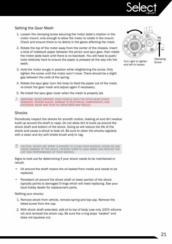
Setting the Gear Mesh1. Loosen the clamping screw securing the motor plate’s rotation in the
motor mount, only enough to allow the motor to rotate in the mount. Check and ensure there is no debris in the gears affecting the mesh.
2. Rotate the top of the motor away from the center of the chassis, insert a strip of notebook paper between the pinion and spur gear, then rotate the motor plate back until there is no backlash. You will have to push/twist relatively hard to ensure the paper is pressed all the way into the teeth.
3. Hold the motor snugly in position while retightening the screw. Only tighten the screw until the motor won’t move. There should be a slight gap between the coils of the spring.
4. Rotate the spur gear (turn the tires) to feed the paper out of the mesh, re-check the gear mesh and adjust again if necessary.
5. Re-install the spur gear cover when the mesh is properly set.
WARNING: NEVER OPERATE YOUR VEHICLE WITH THE SPUR GEAR COVER REMOVED. SEVERE INJURY, DAMAGE TO ELECTRICAL COMPONENTS, AND EXCESSIVE WEAR AND TEAR ON DRIVETRAIN MAY RESULT.
ShocksPeriodically inspect the shocks for smooth motion, leaking oil and dirt residue build up around the shaft or caps. Do not allow dirt to build up around the shock shaft and bottom of the shock. Doing so will reduce the life of the shock and cause a shock to leak oil. Be sure to clean the shocks regularly with a clean and dry soft bristle brush and/or rag.
CAUTION: NEVER USE SPRAY CLEANERS TO CLEAN YOUR SHOCKS, DOING SO CAN CAUSE DAMAGE TO THE SEALS, CAUSING THEM TO LEAK MORE AND REDUCE THE LIEF AND PERFORMANCE OF YOUR SHOCKS.
Signs to look out for determining if your shock needs to be maintained or rebuilt.
• Oil around the shaft means the oil leaked from inside and needs to be replaced.
• Persistent oil around the shock shaft or lower portion of the shock typically points to damaged O-rings which will need replacing. See your local hobby dealer for replacement parts.
Refilling your shocks:
1. Remove shock from vehicle, remove spring and top cap. Remove the bleed screw from the cap.
2. With shock shaft extended, add oil to top of body (use only 100% silicone oil) and reinstall the shock cap. Be sure the o-ring stays “seated” and does not squeeze out.
Turn right to tighten and left to loosen
Clamping Screw

22
3. Slowly compress the shock shaft 100% of travel using a towel or paper napkin to clean up overflowed oil, then reinstall the bleed screw. Do not over-tighten.
4. Check for free motion of shock. If the shock feels like it gets stiffer at the end of compression, there is too much oil or air. Compress the shaft and remove the bleed screw slowly to allow excess air/oil to come out, then reinstall the screw.
5. It is normal for the shock to rebound (with the spring removed) after full compression and release.
Replacing the O-rings:
• Disassemble shock and remove shock end and shaft from the body.
• Carefully remove lower cap by unscrewing from the shock body.
• Remove the O-ring and spacer and replace with genuine replacement parts.
• Re-assemble the shock following the refilling instructions above.
Tires and WheelsInspect the tires to ensure they have adequate tread and they are properly glued to the wheels. The tires on your vehicle come pre-glued from the factory; however after running your vehicle it is possible for the glue to come loose in some areas.
• To reattach the tire to the wheel, use hobby grade Cyanoacrylate (CA) glue and apply small amounts (one drop at a time) between the tire and wheel. Allow the glue to fully dry before operating your vehicle.
• When reinstalling tires, use caution when tightening the nuts that secure the wheels to the vehicle. Ensure the wheels rotate freely but don’t wobble excessively. Over tightening the wheels may cause excess strain on the electrical and mechanical components of your vehicle. Operating your vehicle under these conditions will void your warranty.
• Taking the above into consideration, leaving wheels too loose can cause them to strip. It is recommended to check that the wheel nuts are tight every time you run your vehicle.
• Consequently running your vehicle will cause the tires to eventually wear out. Be sure to obtain and use genuine replacement parts from your local hobby dealer when necessary.
General Wear and TearUsing your vehicle will cause general wear and tear which is not covered under warranty yet may necessitate replacement of components. Continued operation of your product with worn components may cause continued damage to other components.
Be sure to regularly inspect your vehicle and accessories for excess wear and damaged components.
23
Storage and Disposal
Storage• Always store all equipment in a cool dry place when not in use.
• Always disconnect the batteries before storage.
• Never store the transmitter or receiver in direct sunlight for extended periods of time.
• Never store the transmitter with batteries installed for extended periods of time. Doing so may allow the batteries to leak and cause permanent damage to the transmitter.
• Always disconnect electrical connections after use in wet environments. Allowing the contacts to dry will reduce corrosion.
DisposalYour product is considered electronic waste and should never be discarded in standard garbage containers. Please visit your local hobby dealer (and some home improvement centers) and use the FREE battery disposal center for proper disposal/recycling. Consult your local city hall for information on recycling other electronic waste.
Troubleshooting ProblemsBefore contacting customer support, recall that this is a hobby grade product intended to be user serviceable. Please take the time to fully inspect your product for any obvious causes to the issues you are experiencing. Below are some of the most common issues experienced. Scan the QR code to the right with your smart phone for quick access to the product support content on our website.
• Many control issues can be resolved by simply re-pairing the transmitter and receiver, always start here.
• Dead transmitter or vehicle batteries will cause the product to malfunction and not work properly. As with TV remote controls in your home, if the batteries are dead, they don’t work. Start power related troubleshooting with fresh batteries in the transmitter and recharged batteries in the vehicle.
• Power connections between the Battery, ESC and receiver are critical to the performance of the product. Running in various debris may cause foreign objects to snag on wires, causing connections to come loose. It is a good idea to unplug and reconnect motor and battery connections when beginning power related troubleshooting. Also inspect for any damage caused to the antenna.
• Drivetrain issues can mask themselves as power related. Fully inspect the wheels, driveshafts, and motor for foreign objects that may have
24
become tangled or wrapped around the spinning parts of the drivetrain. Small objects like fishing line for example, can wrap around a drive shaft, overheat and melt due to the friction and cause the entire drivetrain to lock up. Although a big problem, it can be difficult to see when inspecting. Always remove the wheels from your vehicle when troubleshooting drivetrain related issues.
• The drivetrain in your vehicle has a covered shaft to protect from debris. We encourage you to remove it and inspect under the cover to ensure that items have not been entangled around the shaft causing drag and possible failure. Inspect around the steering components to ensure no debris are preventing normal steering operation.
• Steering can become sluggish once components get dirty or “take a set” after running. Inspect the rod ends of the turnbuckles to ensure they are properly aligned and not binding. You should be able to grab a turnbuckle with your fingers and rotate it easily.
• Healthy gears are crucial to a properly functioning vehicle. If you hear your vehicle making very loud noises, you should immediately stop and check the gears for foreign debris. Even a small pebble can get lodged into the teeth of the pinion gear, which would practically destroy the spur gear in a very short period of time.

25
Appendix A: Troubleshooting Guide for the Reaktor Power System
Problem / Symptom Possible Cause Possible Solution
ESC will not set to transmitter
Receiver and transmitter not bound Try re-pairing
Throttle Channel not set to Reverse Unless using Futaba radio, set Th channel to Re-verse
Batteries dead in car or transmitter Replace batteriesTransmitter is too close to vehicle Hold transmitter farther away from vehicle
After turning ON, the motor won’t work and no sound comes from motor
The connections between the bat-tery and the ESC are not correct
Check the power connections. Replace the connec-tors if they are worn or damaged
Car slowed down or stopped drastically during run
Battery voltage too low, LVC active Charge or change batteries
ESC over-temp protection active Turn off ESC and allow ESC and motor to cool before running again
ESC Over current protection active
Change operating conditions to ones that are not as hard on the electronics, i.e. move from grass to asphalt.Reduce pinion gear size on the motor to reduce load on the ESC
Car doesn’t accelerate Ensure the proper punch mode is used Change punch mode based on battery you are using
Reverse not working
Reverse mode has been disabled in ESC Follow setup instructions to turn back on
ESC was improperly set to trans-mitter
Re-set to transmitter, ensure Th channel is set to Reverse for non Futaba transmitters
EPA on transmitter has been turned down for reverse
Adjust EPA’s to 100% and recalibrate ESC to trans-mitter
Motor only goes in reverse or goes in reverse when I pull trigger to go forward
Throttle Channel not set to Reverse Unless using Futaba radio, set Th channel to Re-verse and reset ESC to transmitter
Motor connected to ESC improperly Switch any two motor wiresEPA on transmitter has been turned down for reverse Adjust EPA’s to 100% and reset ESC to transmitter

26
Appendix B: Troubleshooting Guide
Problem / Symptom Possible Cause Possible Solution
Vehicle will not turn onBattery voltage too low Charge batteryBattery not connected Re/connect batteryDamaged battery Replace battery
Transmitter will not turn on
Battery voltage too low Charge or change batteriesBattery/ies installed improperly Correct installation
Short radio range (Vehicle stops responding to transmitter at short distances)
Damaged or improperly installed receiver and antenna
Check receiver antenna for damage. Ensure antenna is properly installed in tube and mount, extending perpendicular from the ground. Ensure all connections are secure
Receiver is malfunctioning Replace receiver
Battery voltage too low Replace or recharge batteries in transmitter and vehicle
Steering not responding as expected
Trim not set properly Adjust steering trimScrews too tight on steering parts Adjust screws to allow for free motion
Fasteners have become loose Check and tighten all fasteners to as-new condition, be careful to not over tighten
Vehicle not responding as expected to transmitter
Trims not set properly Adjust throttle and/or steering trimRadio system lost pair Re-pair radio system
Bad electrical connections Check motor and battery plugs to ensure they are fully connected
Wheels twitch while vehicle is idle (controls at neutral)
Transmitter too close to receiver (<1m) Increase distance between the units
Receiver wire damaged Inspect antenna for damage and replace if necessaryReceiver antenna not installed in vertical position Install in mount with care to not damage antenna wire
Steering will not trim straight, always has right or left bias
Binding in steering system Inspect and correct any binding components or loosen screws if over tight
Front wheels too tight Check and adjust wheel nuts to ensure the wheels are not too tight
Vehicle top speed and acceleration is slow
Battery voltage too low Charge battery
Drivetrain has too much friction Check for debris/excessive wear on gears, inspect bearings
Gear mesh too tight Loosen gear meshPinion gear is loose Check and tighten set screw on motor pinion
Broken DifferentialCheck differential and ensure the outdrives are secured and gears intact. You should not be able to pull them out
Drive pin missing Check for missing wheel pins (behind wheel hexes), or dogbone pins
ESC not set to transmitter Follow ESC instructions to set to transmitterWheels not spinning freely
Wheels too tight Check and adjust wheel nutsDifferentials stripped Check differentials and replace/repair if necessary
Battery charge stops lasting as long as it used to
The battery has become old Replace battery
Battery not charged completely due to insufficient charge time
Charge for longer period of time or try a peak detection charger. We recommend the Radient Primal (RDNA0001)
Gear mesh too tight Check and reset gear mesh settingCharger, battery, wires, or plug has malfunctioned
Check all connections and wires for damage or excessive wear and replace if necessary
Shocks and/or arms covered in oil
Shock O-ring seals are worn Replace O-rings and refill shock with oilTop shock cap too loose or over tightened Check tightness (finger tight), refill shock oil
Bottom shock cap dislodged Check installation, refill shock oil
Spur gears strippingGear mesh too loose Tighten gear mesh for proper backlashFasteners loose or missing Check for loose fasteners and bad bearings.Pinion gear too worn out Replace pinion gear

27
Shim, 5x0.80mm
HLNS1253
SHSS, M4x4mm
HLNA1255
Shim, 5x0.30mm
HLNS1234HLNS1252
HLNS1111
HLNS1055
HLNA1254
HLNS1010
HLNS1253
BALLBEARING, 8x12x3.5MM
fhcs, M2.5x8mm
HLNS1255
HLNS1010
HLNS1155
BALL BEARING, 10x15x4mm
HLNS1069 1.5x8.0mm
11T M1.0
HLNS1254
HLNS1112
SPUR GEAR, 32P, 52T
HLNS1254
HLNS1242
HLNS1174
HLNS1158
HLNS1175
HLNS1070
HLNS1158fhcs, M2.5x8mm
HLNS1054
HLNS1176ball bearing, 5x10x4mm
HLNS1255
HLNS1077
HLNS1256
HLNS1240
ball bearing, 10x15x4mm
HLNS1174
fhcs, M2.5x8mm
HLNS1255
Shim, 5x0.8MM
HLNS1254
HLNS1010
HLNS1253
HLNS1253
HLNS1010
HLNS1174
ball bearing, 10x15x4mm
HLNS1255
HLNS1173
HLNS1212
HLNS1158
Shim, 5X0.8MM
HLNS1255
1.5x8.0mm
HLNS1077
HLNS1212
HLNS1254
HLN1254
HLNS1241 42T M1.0
Appendix C: Differential Exploded Views

28
HLNS1239
HLNS1236
HLNS1228
HLNS1236
HLNS1232
HLNS1233
HLNS1228
HLNS1234
HLNS1072
HLNS1228
55mm
HLNS1232
HLNS1233
HLNS1227 HLNS1228
HLNS1228
HLNS1230HLNS1234
HLNS1238
HLNS1234
HLNS1231
HLNS1228
HLNS1228
HLNS1235
HLNS1228
HLNS1228
HLNS1227
HLNS1233
HLNS1233
HLNS1228
HLNS1235
HLNS1234
HLNS1072
HLNS1231
HLNS1234
HLNS122952mm
Appendix D: Shock Exploded Views

29
Appendix F: Front Suspension Exploded View
HLN
S117
4
ball
bear
ing,
10x
15x4
mm
HLN
S116
7
HLN
S121
0
HLN
S121
4
HLN
S107
8
HLN
S104
5
HLN
S118
3 M
4x0.
7mm
LOC
KN
UT,
FLA
NG
ED
,
HLN
S116
5
HLN
S100
2
HLN
S102
6
fhcs
, M4x
10m
m
HLN
S116
3
FLA
NG
ED
LO
CK
NU
T, M
3x0.
5
HLN
S118
4
HLN
S125
1H
LNS1
168
bhcs
, M3x
16m
m
HLN
S126
5H
LNS1
228
HLN
S118
5
bhcs
, M3x
16m
m
HLN
S116
8
FLA
NG
ED
NU
T, M
3x0.
5mm
HLN
S116
6
HLN
S121
5
HLN
S122
3
SE
T S
CR
EW
, M3x
20m
m
HLN
S120
3
HLN
S116
1
bhcs
, M3x
8mm
HLN
S116
4bh
cs, M
3x10
mm
HLN
S116
5
HLN
S120
8
HLN
S121
9
HLN
S121
9HLN
S122
4H
LNS1
165
HLN
S100
6
HLN
S116
6
bhcs
, M3x
10m
m
bhcs
, M3x
10m
m
, M2.
5x4m
m
bhcs
, M3x
16m
m
HLN
S126
5
HLN
S122
5
HLN
S116
2
HLN
S126
3
HLN
S116
4
fhcs
, M4x
10m
m
bhcs
, M3x
8mm
HLN
S103
8
HLN
S118
1
HLN
S120
1
HLN
S122
4
fhcs
, M3x
15m
m
HLN
S121
8
HLN
S118
0
HLN
S121
6
HLN
S126
3H
LNS1
182
HLN
S120
5
HLN
S120
5
HLN
S120
4
HLN
S118
1
HLN
S120
4
bhcs
, M3x
10m
m
bhcs
, M4x
12m
mH
LNS1
183
HLN
S121
3
bhcs
, M4x
12m
m
HLN
S116
5bh
cs, M
3x10
mm
HLN
S116
5
HLN
S115
6
HLN
S117
4
HLN
S126
6
HLN
S125
1
30
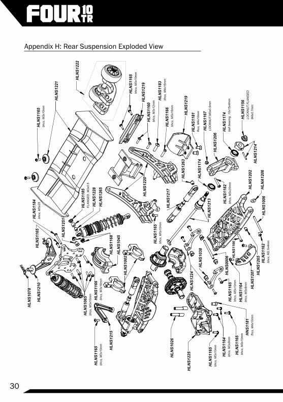
Appendix H: Rear Suspension Exploded View
FLAN
GED
, M3x
0.5
HLN
S122
8
HLN
S118
5
HLN
S000
6
HLN
S116
2
bhcs
, M3x
25H
LNS1
184
HLN
S121
4
bhcs
, M4x
16m
m
HLN
S115
6
HLN
S122
4
HLN
S121
3
HLN
S122
1
HLN
S121
9
HLN
S121
7
HLN
S121
0
HLN
S107
8
bhcs
, M2.
5x4m
m
HLN
S121
5
HLN
S116
5bh
cs, M
3x10
mm
HLN
S122
0 HLN
S126
3
HLN
S116
5bh
cs, M
3x10
mm
HLN
S104
5
HLN
S116
5
HLN
S122
2
bhcs
, M3x
10m
m
HLN
S102
6
HLN
S116
5
HLN
S122
5 HLN
S116
5 fhcs
, M4x
10m
m
HLN
S126
5
HLN
S126
5H
LNS1
207
bhcs
, M3x
10m
m HN
S118
1
HLN
S116
5
fhcs
, M4x
10m
m
bhcs
, M3x
10m
m
HLN
S118
1
HLN
S120
6
HLN
S100
2
HLN
A12
06H
LNS1
006
HLN
S103
8
bhcs
, M3x
10m
mH
LNS1
165
HLN
S116
5
bhcs
, M3x
8mm
HLN
S116
4
bhcs
, M3x
16m
m
HLN
S125
1
bhcs
, M3x
8mm
HLN
S116
6
HLN
S120
2
HLN
S117
4ba
ll be
arin
g, 1
0x15
x4m
m
HLN
S116
6bh
cs, M
3x16
mm
bhcs
, M3x
10m
m
HLN
S121
9
HLN
S116
4
bhcs
, M3x
12m
m
M4x
0.7m
m
HLN
S118
3
LOC
KNU
T,FL
ANG
ED
LOC
KNU
T,M
3x0.
5mm
HLN
S116
7
bhcs
, M3x
20m
m
HLN
S117
4
HLN
S118
2
HLN
S106
5bh
cs, M
3x10
mm
HLN
S116
0
HLN
S116
8
HLN
S116
6

31
Appendix I: Main Chassis Exploded View
HLN
S105
7
bhcs
, M3x
8mm
HLN
S126
3
bhcs
, M3x
6mm
bhcs
, M3x
10m
m
pini
on g
ear,
15T
HLN
S103
5
HLN
S101
2
HLN
S105
2
KN
NS0
008
HLN
S115
4
HLN
S126
4
HLN
S116
9
HLN
S100
4
HLN
S103
2
HLN
S103
2
HLN
S105
0
HLN
S101
9
HLN
S100
3
HLN
S116
5
HLN
S116
7 M
3 LO
CK
NU
T
HLN
S116
4bh
cs, M
3x8m
m
HLN
S118
0
bhcs
, M3x
8mm
fhcs
, M3X
15m
m
HLN
S116
4
Bal
l Bea
ring,
5x8
x2.5
mm
HLN
S106
4
RD
NA
0197 H
LNS1
251
HLN
S125
1
HLN
S105
0
HLN
S117
7
HLN
S115
4bh
cs, M
3x6m
m
HLN
S105
6
bhcs
, M3x
10m
m
HLN
S116
6
bhcs
, M3x
8mm
HLN
S101
6
M3x
0.5x
3mm
HLN
S116
4
bhcs
, M3x
8mm
RD
NA
0366
HLN
S116
4
bhcs
, M3x
8mm
HLN
S116
4
bhcs
, M3x
16m
m
HLN
S103
6
HLN
S115
9H
LNS1
074
HLN
S116
5bh
cs, M
3x10
mm
HLN
S116
5
HLN
S126
3
HLN
S125
8

32
Appendix J: Spare Parts ListHLNS1180 Flat Head Cap Screws (FHCS) M3 x 15mm (10)
HLNS1182 Button Head Cap Screws (BHCS) M3 x 20mm (10)
HLNS1186 Button Head Cap Screws (BHCS) M3 x 15mm (10)
HLNS1187 Button Head Cap Screws (BHCS) M3 x 23mm (10)
HLNS1188 Solid Pin, 2 x 16mm (10)
HLNS1189 Socket Head Set Screws (SHSS) M4 x 20mm (10)
HLNS1190 Button Head Cap Screws (BHCS) M4 x 15mm (10)
HLNS1191 Flanged Nylon Lock Nuts, M5 (10)
HLNS1201 Suspension Arm, Front
HLNS1202 Suspension Arm, Rear
HLNS1203 Wheel And Tire
HLNS1204 Spindle, Front, L-R
HLNS1205 Spindle Carrier, Front, L-R
HLNS1206 Hub, Rear, L-R
HLNS1207 Mud Guard, Suspension Arm, Rear
HLNS1208 Tower, Front
HLNS1209 Tower, Rear
HLNS1210 Body Mount, F-R
HLNS1211 Sway Bar Set, F
HLNS1212 Outdrive, Differential, F-R, Steel
HLNS1213 Driveshaft Set, F-R, Steel
HLNS1214 Wheel Hex, 17mm
HLNS1215 Brace Set, Chassis, F-R
HLNS1216 TurnBuckle Set, Front, Camber
HLNS1217 TurnBuckle Set, Rear, Camber
HLNS1218 TurnBuckle Set, Steering
HLNS1219 Bumper Set, F-R
HLNS1220 Wingstay
HLNS1221 Wing
HLNS1222 Wheelie Bar Set
HLNS1223 Rod End Set
HLNS1224 Arm Holder, (2)
HLNS1225 Lower Kick Plates, F-R
HLNS1226 Steering Post Set, Metal
HLNS1227 Dust Boot, Shock, 13mm

33
HLNS1228 Shock Plastic Kit, 13mm
HLNS1229 Shock Shaft Set, Front, 52mm
HLNS1230 Shock Shaft Set, Rear, 55mm
HLNS1231 Shock Body, Front, 13mm
HLNS1232 Shock Body, Rear, 13mm
HLNS1233 Shock Cap, F-R, 13mm
HLNS1234 Seal Set, Shock, 13mm
HLNS1235 Spring Set, Shock, Front, Standard, 13mm
HLNS1236 Spring Set, Shock, Rear, Standard, 13mm
HLNS1237 Shaft, Center, Steel
HLNS1238 Shock Set, Front, 13mm
HLNS1239 Shock Set, Rear, 13mm
HLNS1240 Differential, F-R
HLNS1241 Ring Gear, Differential, 32T, M1.0
HLNS1242 Pinion Gear, Bevel 11T, M1.0
HLNS1243 Body, Blue, Pre-cut
HLNS1244 Body, Red, Pre-cut
HLNS1245 Body, Clear, Pre-cut
HLNS1246 Spring Set, Shock, Front, Soft, 13mm
HLNS1247 Spring Set, Shock, Rear, Soft, 13mm
HLNS1248 Spring Set, Shock, Front, Hard, 13mm
HLNS1249 Spring Set, Shock, Rear, Hard, 13mm
HLNS1250 Swaybar Set, Rear
HLNS1251 Pivot Ball Flanged, 6.8mm
HLNS1252 Outdrive, Center
HLNS1253 Differential Case, HD
HLNS1254 Seal Set, Differential Case, HD
HLNS1255 Shim Kit, Differential Case, HD
HLNS1256 Differential, Center
HLNS1257 Differential Housing Alum, Center
HLNS1258 Main Chassis
HLNS1259 Pinion Gear, 32P 13T
HLNS1260 Differential Internal Gears M0.8 with shims
HLNS1261 Steering Bushings
HLNS1262 LED Light Kit
HLNS1264 TurnBuckle Set, Steering, Draglink

34
HLNS1265 Pivot Ball, 5.8mm
HLNS1266 Input Shaft Assembly, Front
HLNS1267 Hinge Pin Set
HLNS1268 Hinge Pin Bushings
RDNA0365 ESC, Reaktor 120T BL,NS,WP-P,TSP
RDNA0366 Motor, Reaktor 4T BL,NS 2850 4-pole,TSP

35
HobbyTown Warranty Information
30 DAY LIMITED WARRANTYGeneral Disclaimer: This item is to be free of manufacture defects at time of purchase. This warranty does not cover breakage due to abuse, improper break-in, improper setup, or improper operation.
We at Helion RC have made every effort in component design, material selection and assembly to make our products as durable as possible. Helion products are covered under warranty only against manufacturer’s defect in materials, workmanship or assembly when it is new (before being used).
If you believe a defect in materials, workmanship or assembly was not apparent when the product was new and only became evident after the product was used, then please contact your local HobbyTown® to apply for warranty service. You must provide your original sales receipt verifying the proof-of purchase and date thereof.
Provided warranty conditions have been met, the components that are found to be defective, incorrectly made, or incorrectly assembled within the warranty coverage time period may be repaired or replaced under the sole discretion of HobbyTown®. In the event that your product needs a repair or a replacement part that is not covered by this warranty, your local HobbyTown® dealer can assist you with obtaining the genuine replacement parts and/or accessories to service your Helion RC product.
If you purchased your Helion RC product from a HobbyTown® internet site not affiliated with a local store, please consult that site for its service policies.
JPerkins Distribution Warranty Information
GuaranteeThis product is covered by the current statutory guarantee regulations. If you wish to make a warranty claim, please contact the model shop where you originally purchased the product from. You should also present your proof of purchase.
• The guarantee does not cover faults or damage caused by:
• Incorrect handling or operation
• The use of incompatible accessories
• Modification or unauthorised repairs
• Accidental or deliberate damage
• Normal wear and tear
• Using the product outside of its stated specification
Firelands Group LLC accepts no liability for loss, damage or costs which are incurred due to the incorrect or incompetent use of the product.
36
Model Engines Warranty Information
HELION RC 60 DAY WARRANTYModel Engines (Aust.) Pty. Ltd. warrants this product to be free from defects in materials or workmanship for 60 days from the date of purchase and will repair, replace or refund the purchase should the product prove to be defective.
This warranty does not apply to any unit or system or component which has been dropped, damaged in a crash, improperly installed, assembled, handled or abused.
Model Engines (Aust.) Pty. Ltd. reserves the right to void the warranty if the product has been altered or modified, has had a foreign part added, has been misused or not used for the purpose for which it was designed, has been used near or in salt water, has been water damaged, or if the damage has been caused by the customer’s use of the product.
Under no circumstances does Model Engines (Aust.) Pty. Ltd. warrant nor will the consumer be entitled to consequential or incidental damages. Model Engines (Aust.) Pty. Ltd. assumes no responsibility for any other damage, inconvenience or other claims whatsoever.
LODGING A CLAIMTo lodge a claim, present the goods to your place of purchase (retailer where you bought the product) with your original purchase receipt and a written explanation of the defect.
The place of purchase (retailer where you bought the product) will then contact Model Engines (Aust.) Pty. Ltd. for a Return Authority number and will return the item for warranty assessment to Model Engines (Aust.) Pty. Ltd.. Items delivered to Model Engines (Aust.) Pty. Ltd. for warranty assessment without a Return Authority number will be returned to sender.
The warranty process may take up to 14 business days from the date of receipt. Model Engines (Aust.) Pty. Ltd. must assess each item and if warranty applies must repair or replace the item at its discretion and return it to the place of purchase (retailer where you bought the product).
Goods presented for warranty may be replaced by refurbished goods of the same type rather than being repaired. Refurbished parts may be used to repair the goods.
If the product is proved to be defective the cost and expenses relating to the delivery of the goods to Model Engines (Aust.) Pty. Ltd., will be borne by Model Engines (Aust.) Pty. Ltd..
The benefits of this warranty are in addition to other rights and remedies of the customer under any law to which this warranty relates.
Our goods come with guarantees that cannot be excluded under the Australian consumer Law. You are entitled to a replacement or refund for a major failure and for compensation for any other reasonably foreseeable loss or damage. You are also entitled to have the goods repaired or replaced if

37
the goods fail to be of acceptable quality and the failure does not amount to a major failure.
Model Engines (Aust) Pty.Ltd P.O. Box 828 Noble Park Victoria 3174
www.modelengines.com.au
www.modelengines.com.au Ph (03) 8793 5555 [email protected]
This warranty information relates to goods supplied on a wholesale basis by Model Engines (Aust.) Pty. Ltd. to Australian Retailers. The warranty complies with Australian regulatory requirements and supersedes all warranty information from the original manufacturer.
Declaration of Conformity
CE Conformity DeclarationThis device has been tested in accordance with the relevant harmonised European directives. This product’s design fulfils the protective aims of the European Community relating to the safe operation of this equipment. For a copy of the Declaration of Conformity, please visit: www.helion-rc.com/support
DisposalElectrical equipment marked with the crossed out wheelie bin symbol must not be disposed of in household waste, but must be taken to a specialist disposal or recycling system. In EU member countries, electrical equipment must not be discarded via the normal domestic refuse channels (WEEE - Waste Electrical and Electronic Equipment Directive 2002/96/EG). You should take unwanted electrical equipment to your nearest local authority waste collection point or recycling centre.
Distributed in the UK by:
J Perkins Distribution Ltd, Lenham, Kent, UK ME17 2DL. www.jperkins.com

Scan this QR code with yoursmartphone for more information
www. Helion-RC.com