Embed Size (px)
Citation preview

owner’s manual
MODEL 5907
2 • SLAYER PRO 4X4
INTRODUCTION
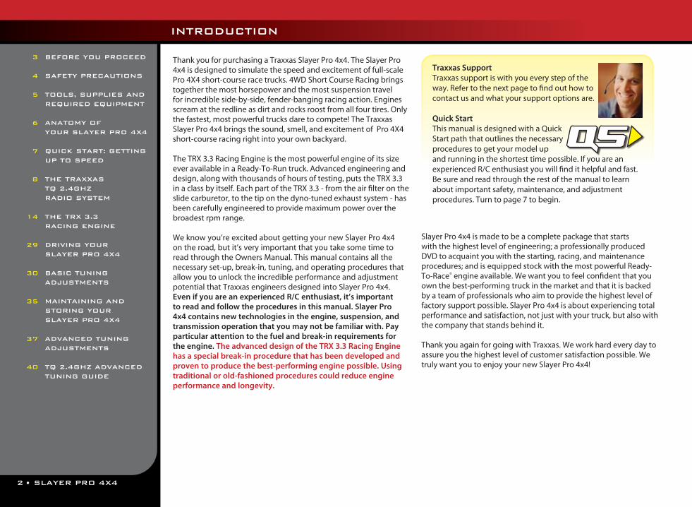
Thank you for purchasing a Traxxas Slayer Pro 4x4. The Slayer Pro 4x4 is designed to simulate the speed and excitement of full-scale Pro 4X4 short-course race trucks. 4WD Short Course Racing brings together the most horsepower and the most suspension travel for incredible side-by-side, fender-banging racing action. Engines scream at the redline as dirt and rocks roost from all four tires. Only the fastest, most powerful trucks dare to compete! The Traxxas Slayer Pro 4x4 brings the sound, smell, and excitement of Pro 4X4 short-course racing right into your own backyard.
The TRX 3.3 Racing Engine is the most powerful engine of its size ever available in a Ready-To-Run truck. Advanced engineering and design, along with thousands of hours of testing, puts the TRX 3.3 in a class by itself. Each part of the TRX 3.3 - from the air filter on the slide carburetor, to the tip on the dyno-tuned exhaust system - has been carefully engineered to provide maximum power over the broadest rpm range.
We know you’re excited about getting your new Slayer Pro 4x4 on the road, but it’s very important that you take some time to read through the Owners Manual. This manual contains all the necessary set-up, break-in, tuning, and operating procedures that allow you to unlock the incredible performance and adjustment potential that Traxxas engineers designed into Slayer Pro 4x4. Even if you are an experienced R/C enthusiast, it’s important to read and follow the procedures in this manual. Slayer Pro 4x4 contains new technologies in the engine, suspension, and transmission operation that you may not be familiar with. Pay particular attention to the fuel and break-in requirements for the engine. The advanced design of the TRX 3.3 Racing Engine has a special break-in procedure that has been developed and proven to produce the best-performing engine possible. Using traditional or old-fashioned procedures could reduce engine performance and longevity.
Slayer Pro 4x4 is made to be a complete package that starts with the highest level of engineering; a professionally produced DVD to acquaint you with the starting, racing, and maintenance procedures; and is equipped stock with the most powerful Ready-To-Race® engine available. We want you to feel confident that you own the best-performing truck in the market and that it is backed by a team of professionals who aim to provide the highest level of factory support possible. Slayer Pro 4x4 is about experiencing total performance and satisfaction, not just with your truck, but also with the company that stands behind it.
Thank you again for going with Traxxas. We work hard every day to assure you the highest level of customer satisfaction possible. We truly want you to enjoy your new Slayer Pro 4x4!
3
4
5
6
7
8
14
29
30
35
37
40
BEFORE YOU PROCEED
SAFETY PRECAUTIONS
TOOLS, SUPPLIES AND REQUIRED EQUIPMENT
ANATOMY OF YOUR SLAYER PRO 4X4
QUICK START: GETTING UP TO SPEED
THE TRAXXAS TQ 2.4GHZ RADIO SYSTEM
THE TRX 3.3 RACING ENGINE
DRIVING YOUR SLAYER PRO 4X4
BASIC TUNING ADJUSTMENTS
MAINTAINING AND STORING YOUR SLAYER PRO 4X4
ADVANCED TUNING ADJUSTMENTS
TQ 2.4GHZ ADVANCED TUNING GUIDE
Traxxas SupportTraxxas support is with you every step of the way. Refer to the next page to find out how to contact us and what your support options are.
Quick StartThis manual is designed with a Quick Start path that outlines the necessary procedures to get your model up and running in the shortest time possible. If you are an experienced R/C enthusiast you will find it helpful and fast. Be sure and read through the rest of the manual to learn about important safety, maintenance, and adjustment procedures. Turn to page 7 to begin.
SLAYER PRO 4X4 • 3
BEFORE YOU PROCEED
Carefully read and follow all instructions in this and any accompanying materials to prevent serious damage to your model. Failure to follow these instructions will be considered abuse and/or neglect.
Before running your model, look over this entire manual and examine the model carefully. If for some reason you decide it is not what you wanted, then do not continue any further. Your hobby dealer absolutely cannot accept a model for return or exchange after it has been run.
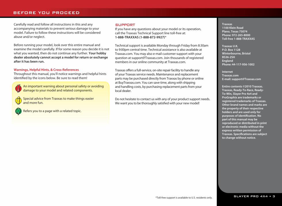
Warnings, Helpful Hints, & Cross-ReferencesThroughout this manual, you’ll notice warnings and helpful hints identified by the icons below. Be sure to read them!
An important warning about personal safety or avoidingdamage to your model and related components.
Special advice from Traxxas to make things easier and more fun.
Refers you to a page with a related topic.
SUPPORTIf you have any questions about your model or its operation, call the Traxxas Technical Support line toll-free at: 1-888-TRAXXAS (1-888-872-9927)*
Technical support is available Monday through Friday from 8:30am to 9:00pm central time. Technical assistance is also available at Traxxas.com. You may also e-mail customer support with your question at [email protected]. Join thousands of registered members in our online community at Traxxas.com.
Traxxas offers a full-service, on-site repair facility to handle any of your Traxxas service needs. Maintenance and replacement parts may be purchased directly from Traxxas by phone or online at BuyTraxxas.com. You can save time, along with shipping and handling costs, by purchasing replacement parts from your local dealer.
Do not hesitate to contact us with any of your product support needs. We want you to be thoroughly satisfied with your new model!
Traxxas1100 Klein RoadPlano, Texas 75074Phone: 972-265-8000Toll-free 1-888-TRAXXAS
Traxxas U.K.P.O. Box 1128Winterbourne, Bristol BS36-2SHEnglandPhone: 44-117-956-1002
InternetTraxxas.comE-mail: [email protected]
Entire contents ©2010 Traxxas. Traxxas, Ready-To-Race, Ready-To-Win, Slayer Pro 4x4 and ProGraphix are trademarks or registered trademarks of Traxxas. Other brand names and marks are the property of their respective holders and are used only for purposes of identification. No part of this manual may be reproduced or distributed in print or electronic media without the express written permission of Traxxas. Specifications are subject to change without notice.
*Toll-free support is available to U.S. residents only.
4 • SLAYER PRO 4X4
This model is not intended for use by children (minors) under 16 years of age without the supervision of a responsible and knowledgeable adult.
All instructions and precautions outlined in this manual should be strictly followed to ensure safe operation of your model.
SAFETY PRECAUTIONS
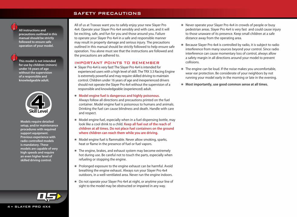
Models require detailed setup, and/or maintenance procedures with required support equipment. Previous experience with radio controlled models is mandatory. These models are capable of very high speeds and require an even higher level of skilled driving control.
Skill Level = Myriad Semi Bold
1 2 3 3+ 4 5bluehighway font
For Expert Drivers
Choose the Mode l That i s R ight For You . For ind iv idua l Mode ls
No previous experience with radio controlled models is required.Models require a minimum of setup, maintenance, or support equipment.
Previous experience with radio controlled models is mandatory. These models are capable of high speeds, requiring experienced driving control. Models require detailed setup, and/or maintenance procedures with required support equipment. Previous experience with radio controlled models is mandatory. These models are capable of very high speeds and require an even higher level of skilled driving control. Models require detailed setup, and/or mainte-nance procedures with required support equipment. For Expert Drivers Only. This product is capable of extreme speed and acceleration! It carries our highest skill level rating and is intended for expert drivers only. Experience with nitro-powered radio controlled models is required!
Previous experience with radio controlled models is recommended.Models require a higher level of setup, maintenance, or support equipment.
No previous experience with radio controlled models is required.Model requires a minimum of setup, maintenance, or support equipment.
Previous experience with radio controlled models is mandatory. This model is capable of high speeds, requiring experienced driving control. Model requires detailed setup, and/or maintenance procedures with required support equipment.
Previous experience with radio controlled models is mandatory. This model is capable of very high speeds and requires an even higher level of skilled driving control. Model requires detailed setup, and/or maintenance procedures with required support equipment.
For Expert Drivers Only. This product is capable of extreme speed and acceleration! It carries our highest skill level rating and is intended for expert drivers only. Experience with nitro-powered radio controlled models is required!
Previous experience with radio controlled models is recommended.Model requires a higher level of setup, maintenance, or support equipment.
BELOW TEXT HAS BEEN UPDATED on 3-14-07Kent wants maintenance text to be at the END of the paragraph.-- KB
All of us at Traxxas want you to safely enjoy your new Slayer Pro 4x4. Operate your Slayer Pro 4x4 sensibly and with care, and it will be exciting, safe, and fun for you and those around you. Failure to operate your Slayer Pro 4x4 in a safe and responsible manner may result in property damage and serious injury. The precautions outlined in this manual should be strictly followed to help ensure safe operation. You alone must see that the instructions are followed and the precautions are adhered to.
IMPORTANT POINTS TO REMEMBER Slayer Pro 4x4 is very fast! The Slayer Pro 4x4 is intended for experienced users with a high level of skill. The TRX 3.3 Racing Engine is extremely powerful and may require skilled driving to maintain control. Children under 16 years of age and inexperienced drivers should not operate the Slayer Pro 4x4 without the supervision of a responsible and knowledgeable (experienced) adult.
Model engine fuel is dangerous and highly poisonous. Always follow all directions and precautions printed on the fuel container. Model engine fuel is poisonous to humans and animals. Drinking the fuel can cause blindness and death. Handle with care and respect.
Model engine fuel, especially when in a fuel dispensing bottle, may look like a cool drink to a child. Keep all fuel out of the reach of children at all times. Do not place fuel containers on the ground where children can reach them while you are driving.
Model engine fuel is flammable. Never allow smoking, sparks, heat or flame in the presence of fuel or fuel vapors.
The engine, brakes, and exhaust system may become extremely
hot during use. Be careful not to touch the parts, especially when refueling or stopping the engine.
Prolonged exposure to the engine exhaust can be harmful. Avoid breathing the engine exhaust. Always run your Slayer Pro 4x4 outdoors, in a well-ventilated area. Never run the engine indoors.
Do not operate your Slayer Pro 4x4 at night, or anytime your line of sight to the model may be obstructed or impaired in any way.
Never operate your Slayer Pro 4x4 in crowds of people or busy pedestrian areas. Slayer Pro 4x4 is very fast and could cause injury to those unaware of its presence. Keep small children at a safe distance away from the operating area.
Because Slayer Pro 4x4 is controlled by radio, it is subject to radio interference from many sources beyond your control. Since radio interference can cause momentary loss of control, always allow a safety margin in all directions around your model to prevent collisions.
The engine can be loud. If the noise makes you uncomfortable, wear ear protection. Be considerate of your neighbors by not running your model early in the morning or late in the evening.
Most importantly, use good common sense at all times.
1
SLAYER PRO 4X4 • 5
TOOLS, SUPPLIES AND REQUIRED EQUIPMENT
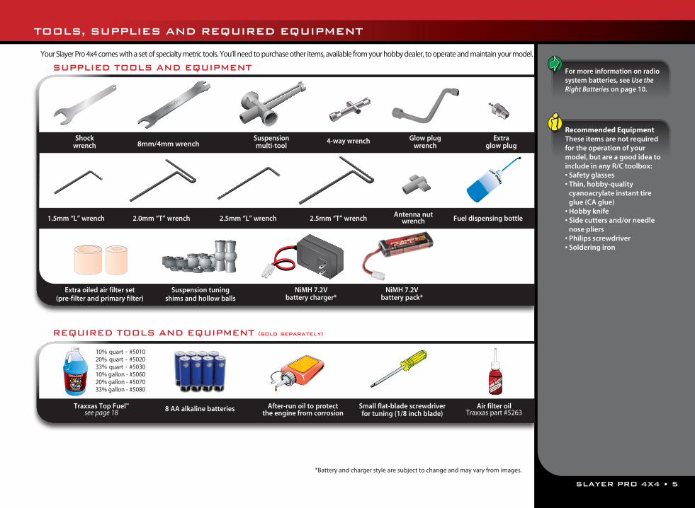
Your Slayer Pro 4x4 comes with a set of specialty metric tools. You’ll need to purchase other items, available from your hobby dealer, to operate and maintain your model.
Recommended EquipmentThese items are not required for the operation of your model, but are a good idea to include in any R/C toolbox:• Safety glasses• Thin, hobby-quality
cyanoacrylate instant tire glue (CA glue)
• Hobby knife• Side cutters and/or needle
nose pliers• Philips screwdriver • Soldering iron
For more information on radio system batteries, see Use the Right Batteries on page 10.
SUPPLIED TOOLS AND EQUIPMENT
REQUIRED TOOLS AND EQUIPMENT (sold separately)
Glow plug wrench
Extra glow plug
1.5mm “L” wrench 2.0mm “T” wrench 2.5mm “T” wrench
Shock wrench
Suspension multi-tool
4-way wrench
Suspension tuning shims and hollow balls
2.5mm “L” wrench
Extra oiled air filter set (pre-filter and primary filter)
Air filter oilTraxxas part #52638 AA alkaline batteriesTraxxas Top Fuel™
see page 18Small flat-blade screwdriver for tuning (1/8 inch blade)
After-run oil to protect the engine from corrosion
Fuel dispensing bottle
10% quart - #5010 20% quart - #502033% quart - #503010% gallon - #5060 20% gallon - #507033% gallon - #5080
Antenna nut wrench
NiMH 7.2V battery pack*
NiMH 7.2V battery charger*
*Battery and charger style are subject to change and may vary from images.
8mm/4mm wrench
6 • SLAYER PRO 4X4
ANATOMY OF THE SLAYER PRO 4X4
Fuel Tank
Fuel Cap Steering Servo
Suspension Arm
Bumper
Skid Plate
Oil Shock (Damper)
Toe Link (Turnbuckle)
Transmission
Air Filter
Exhaust Header
TRX 3.3 Racing Engine see pg. 15 for details
Pressure Line
Fuel Line
EZ-Start Motor
Bulkhead(under chassis)
Body Mount Post
Chassis
Driveshaft (Half Shaft)
On/Off Switch
Throttle Linkage to Throttle/Brake Servo (below filter)
Antenna Mount
Access Plug (for two-speed adjustment)
Pipe Hanger
Receiver Box
Engine Shut-off Clamp
Roll HoopRocker
Push Rod
Pivot Ball
Hex Hub Axle Carrier
Spring Pre-load Adjuster
Disc Brake
Brake Tension Adjuster
Fuel CapHandle Differential
(under chassis)
EZ-Start Plug
Tuned Pipe
SLAYER PRO 4X4 • 7
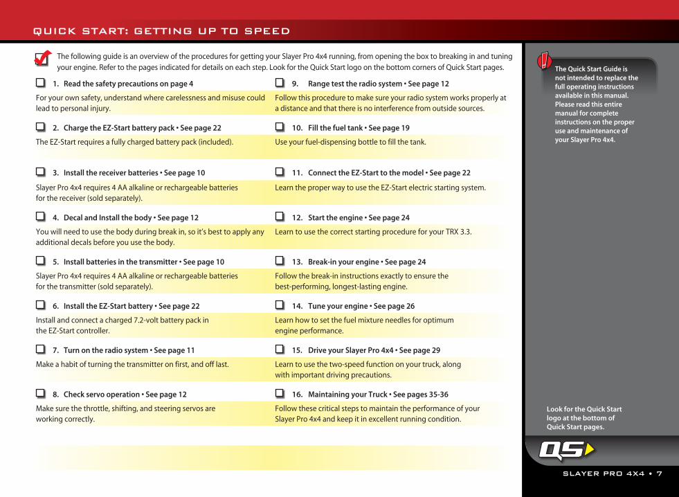
QUICK START: GETTING UP TO SPEED
The following guide is an overview of the procedures for getting your Slayer Pro 4x4 running, from opening the box to breaking in and tuning your engine. Refer to the pages indicated for details on each step. Look for the Quick Start logo on the bottom corners of Quick Start pages.
1. Read the safety precautions on page 4 9. Range test the radio system • See page 12
For your own safety, understand where carelessness and misuse could lead to personal injury.
Follow this procedure to make sure your radio system works properly at a distance and that there is no interference from outside sources.
2. Charge the EZ-Start battery pack • See page 22 10. Fill the fuel tank • See page 19
The EZ-Start requires a fully charged battery pack (included). Use your fuel-dispensing bottle to fill the tank.
3. Install the receiver batteries • See page 10 11. Connect the EZ-Start to the model • See page 22
Slayer Pro 4x4 requires 4 AA alkaline or rechargeable batteries for the receiver (sold separately).
Learn the proper way to use the EZ-Start electric starting system.
4. Decal and Install the body • See page 12 12. Start the engine • See page 24
You will need to use the body during break in, so it’s best to apply any additional decals before you use the body.
Learn to use the correct starting procedure for your TRX 3.3.
5. Install batteries in the transmitter • See page 10 13. Break-in your engine • See page 24
Slayer Pro 4x4 requires 4 AA alkaline or rechargeable batteries for the transmitter (sold separately).
Follow the break-in instructions exactly to ensure the best-performing, longest-lasting engine.
6. Install the EZ-Start battery • See page 22 14. Tune your engine • See page 26
Install and connect a charged 7.2-volt battery pack in the EZ-Start controller.
Learn how to set the fuel mixture needles for optimum engine performance.
7. Turn on the radio system • See page 11 15. Drive your Slayer Pro 4x4 • See page 29
Make a habit of turning the transmitter on first, and off last. Learn to use the two-speed function on your truck, along with important driving precautions.
8. Check servo operation • See page 12 16. Maintaining your Truck • See pages 35-36
Make sure the throttle, shifting, and steering servos are working correctly.
Follow these critical steps to maintain the performance of your Slayer Pro 4x4 and keep it in excellent running condition.
The Quick Start Guide is not intended to replace the full operating instructions available in this manual. Please read this entire manual for complete instructions on the proper use and maintenance of your Slayer Pro 4x4.
Look for the Quick Start logo at the bottom of Quick Start pages.
8 • SLAYER PRO 4X4
TRAXXAS TQ 2.4GHz RADIO SYSTEM
INTRODUCTIONYour model includes the latest Traxxas TQ 2.4GHz transmitter with Traxxas Link™ technology. The transmitter’s easy-to-use design provides instant driving fun for new R/C enthusiasts, and also offers a full compliment of pro-level tuning features for advanced users – or anyone interested in experimenting with the performance of their model. The steering and throttle channels feature adjustable Exponential, End Points, and Sub-Trims. Steering and braking Dual Rate are also available. Many of the next-level features are controlled by the Multi-Function knob, which can be programmed to control a variety functions. The detailed instructions (page 40) and Menu Tree (page 42) included in this manual will help you understand and operate the advanced functions of the new TQ 2.4GHz radio system. For additional information and how-to videos, visit Traxxas.com.
RADIO SYSTEM TERMINOLOGYPlease take a moment to familiarize yourself with these radio and power system terms. They will be used throughout this manual.A detailed explanation of the advanced terminology and features of your new radio system begins on page 40.
2.4GHz Spread Spectrum – This model is equipped with the latest R/C technology. Unlike AM and FM systems that require frequency crystals and are prone to frequency conflicts, the TQ 2.4GHz system automatically selects and locks onto an open frequency, and offers superior resistance to interference and “glitching.”
Current - Current is a measure of power flow through the electronics, usually measured in amps. If you think of a wire as a garden hose, current is a measure of how much water is flowing through the hose.
Frequency band - The radio frequency used by the transmitter to send signals to your model. This model operates on the 2.4GHz direct-sequence spread spectrum.
mAh – Abbreviation for milliamp hour. A measure of the capacity of the battery pack. The higher the number, the longer the battery will last between recharges.
Neutral position - The standing position that the servos seek when the transmitter controls are at the neutral setting.
NiCad - Abbreviation for nickel-cadmium. The original rechargeable hobby pack, NiCad batteries have very high current handling, high capacity, and can last up to 1000 charging cycles. Good charging procedures are required to reduce the possibility of developing a “memory” effect and shortened run times.
NiMH - Abbreviation for nickel-metal hydride. Rechargeable NiMH batteries offer high current handling, and much greater resistance to the “memory” effect. NiMH batteries generally allow higher capacity than NiCad batteries. They can last up to 500 charge cycles. A peak charger designed for NiMH batteries is required for optimal performance.
Receiver - The radio unit inside your model that receives signals from the transmitter and relays them to the servos.
Servo - Small motor unit in your model that operates the steering mechanism.
Transmitter - The hand-held radio unit that sends throttle and steering instructions to your model.
Trim - The fine-tuning adjustment of the neutral position of the servos, made by adjusting the throttle and steering trim knobs on the face of the transmitter. Note: The Multi Function knob must be programmed to serve as a throttle trim adjustment.
2-channel radio system - The TQ radio system, consisting of the receiver, the transmitter, and the servos. The system uses two channels: one to operate the throttle and one to operate the steering.
TQ 2.4GHz RADIO SYSTEM PRECAUTIONS For maximum range, always hold the transmitter
so the antenna is in a vertical position (pointing straight up). The transmitter’s antenna can be swiveled and angled to allow for a vertical position if necessary.
Do not kink the receiver's antenna wire. Kinks in the antenna wire will reduce range.
DO NOT CUT any part of the receiver's antenna wire. Cutting the antenna will reduce range.
Extend the antenna wire in the model as far as possible for maximum range. It is not necessary to extend the antenna wire out of the body, but wrapping or coiling the antenna wire should be avoided.
Do not allow the antenna wire to extend outside the body without the protection of an antenna tube, or the antenna wire may get cut or damaged, reducing range. Always keep the wire protected (in the antenna tube) to prevent the chance of damage. An extra antenna tube has been included with your model in the event that the original tube becomes damaged.
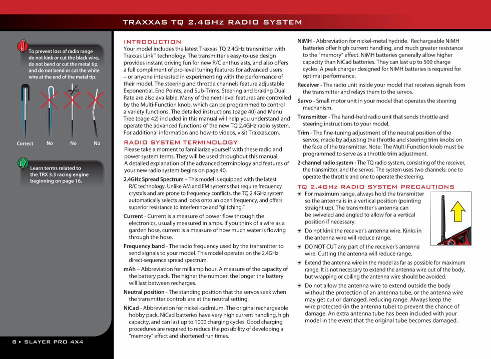
To prevent loss of radio range do not kink or cut the black wire, do not bend or cut the metal tip, and do not bend or cut the white wire at the end of the metal tip.
Correct NoNo No
Learn terms related to the TRX 3.3 racing engine beginning on page 16.
SLAYER PRO 4X4 • 9
TRAXXAS TQ 2.4GHZ RADIO SYSTEM
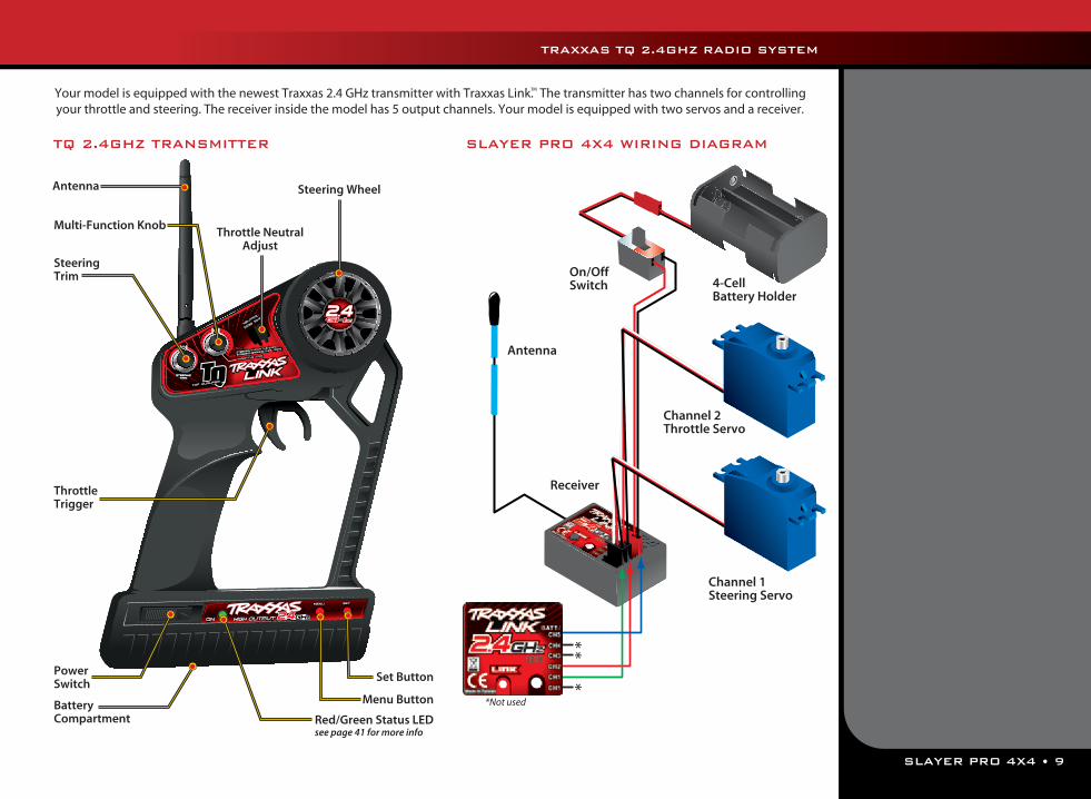
Your model is equipped with the newest Traxxas 2.4 GHz transmitter with Traxxas Link.™ The transmitter has two channels for controlling your throttle and steering. The receiver inside the model has 5 output channels. Your model is equipped with two servos and a receiver.
SLAYER PRO 4X4 WIRING DIAGRAM
Antenna
On/OffSwitch
Receiver
4-CellBattery Holder
Channel 1 Steering Servo
Channel 2 Throttle Servo
TQ 2.4GHZ TRANSMITTER
Antenna
Steering Trim
Multi-Function Knob
Throttle Trigger
Throttle Neutral Adjust
Steering Wheel
Power Switch
Battery Compartment
Set Button
Menu Button
Red/Green Status LEDsee page 41 for more info
*Not used
10 • SLAYER PRO 4X4
If the power indicator doesn’t light green, check the polarity of the batteries. Check rechargeable batteries for a full charge. If you see any other flashing signal from the LED, refer to the chart on page 41 to identify the code.
Use the Right BatteriesYour transmitter uses AA batteries. Use new alkaline batteries, or rechargeable batteries such as NiMH (Nickel Metal Hydride) batteries in your transmitter. Make sure rechargeable batteries are fully charged according to the manufacturer’s instructions.
If you use rechargeable batteries in your transmitter, be aware that when they begin to lose their charge, they lose power more quickly than regular alkaline batteries.
Caution: Discontinue running your model at the first sign of weak batteries (flashing red light) to avoid losing control.
When rechargeable batteries begin to lose their charge, they will fade much faster than alkaline dry cells. Stop immediately at the first sign of weak batteries. Never turn the transmitter off when the battery pack is plugged in. The model could run out of control.
3,5
*Always keep your Quick Reference Guide in your transmitter.
TRAXXAS TQ 2.4GHZ RADIO SYSTEM
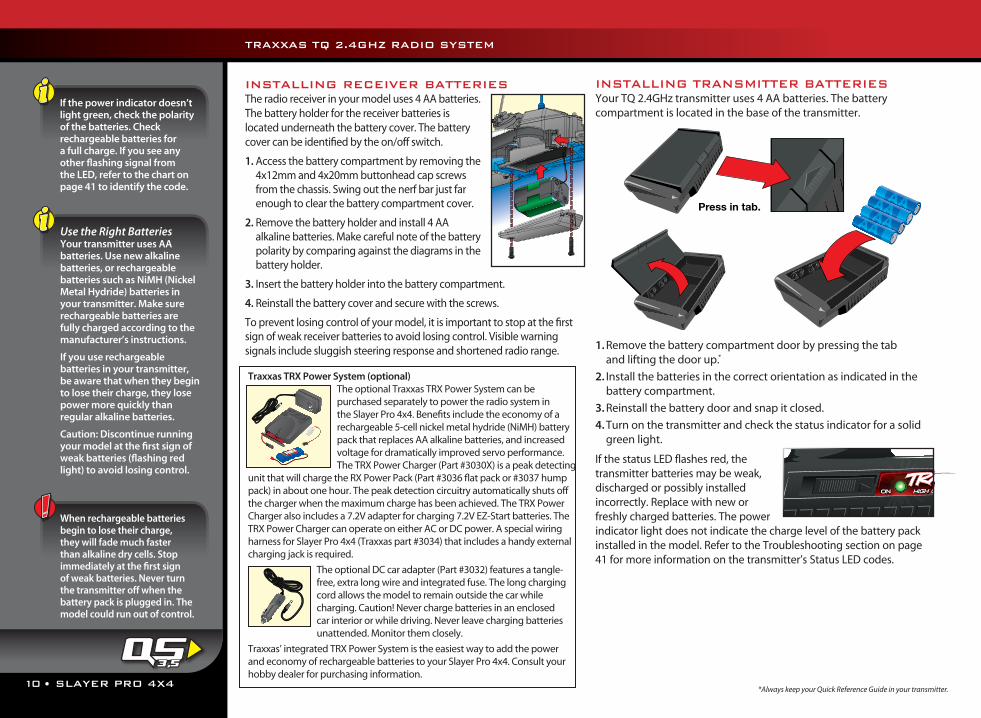
INSTALLING RECEIVER BATTERIESThe radio receiver in your model uses 4 AA batteries. The battery holder for the receiver batteries is located underneath the battery cover. The battery cover can be identified by the on/off switch.
1. Access the battery compartment by removing the 4x12mm and 4x20mm buttonhead cap screws from the chassis. Swing out the nerf bar just far enough to clear the battery compartment cover.
2. Remove the battery holder and install 4 AA alkaline batteries. Make careful note of the battery polarity by comparing against the diagrams in the battery holder.
3. Insert the battery holder into the battery compartment.
4. Reinstall the battery cover and secure with the screws.
To prevent losing control of your model, it is important to stop at the first sign of weak receiver batteries to avoid losing control. Visible warning signals include sluggish steering response and shortened radio range.
INSTALLING TRANSMITTER BATTERIESYour TQ 2.4GHz transmitter uses 4 AA batteries. The battery compartment is located in the base of the transmitter.
1. Remove the battery compartment door by pressing the tab and lifting the door up.*
2. Install the batteries in the correct orientation as indicated in the battery compartment.
3. Reinstall the battery door and snap it closed.
4. Turn on the transmitter and check the status indicator for a solid green light.
If the status LED flashes red, the transmitter batteries may be weak, discharged or possibly installed incorrectly. Replace with new or freshly charged batteries. The power indicator light does not indicate the charge level of the battery pack installed in the model. Refer to the Troubleshooting section on page 41 for more information on the transmitter’s Status LED codes.
Traxxas TRX Power System (optional)The optional Traxxas TRX Power System can be purchased separately to power the radio system in the Slayer Pro 4x4. Benefits include the economy of a rechargeable 5-cell nickel metal hydride (NiMH) battery pack that replaces AA alkaline batteries, and increased voltage for dramatically improved servo performance. The TRX Power Charger (Part #3030X) is a peak detecting
unit that will charge the RX Power Pack (Part #3036 flat pack or #3037 hump pack) in about one hour. The peak detection circuitry automatically shuts off the charger when the maximum charge has been achieved. The TRX Power Charger also includes a 7.2V adapter for charging 7.2V EZ-Start batteries. The TRX Power Charger can operate on either AC or DC power. A special wiring harness for Slayer Pro 4x4 (Traxxas part #3034) that includes a handy external charging jack is required.
The optional DC car adapter (Part #3032) features a tangle-free, extra long wire and integrated fuse. The long charging cord allows the model to remain outside the car while charging. Caution! Never charge batteries in an enclosed car interior or while driving. Never leave charging batteries unattended. Monitor them closely.
Traxxas’ integrated TRX Power System is the easiest way to add the power and economy of rechargeable batteries to your Slayer Pro 4x4. Consult your hobby dealer for purchasing information.
SLAYER PRO 4X4 • 11
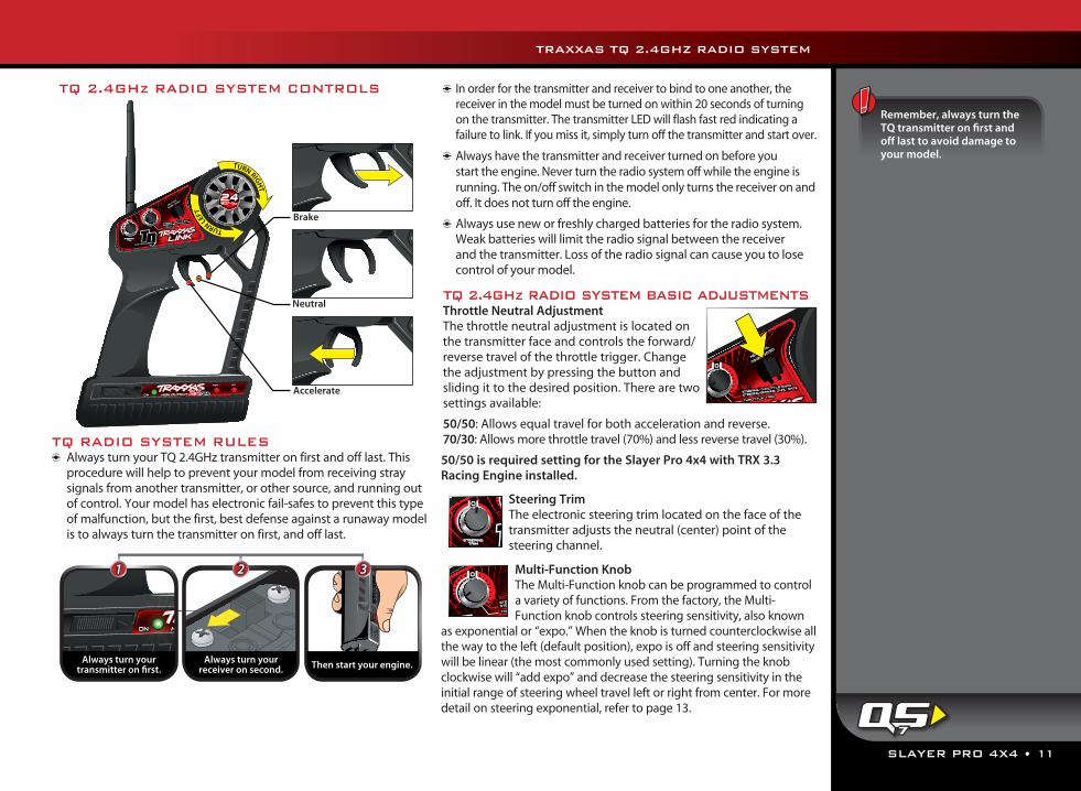
TQ RADIO SYSTEM RULES Always turn your TQ 2.4GHz transmitter on first and off last. This
procedure will help to prevent your model from receiving stray signals from another transmitter, or other source, and running out of control. Your model has electronic fail-safes to prevent this type of malfunction, but the first, best defense against a runaway model is to always turn the transmitter on first, and off last.
In order for the transmitter and receiver to bind to one another, the receiver in the model must be turned on within 20 seconds of turning on the transmitter. The transmitter LED will flash fast red indicating a failure to link. If you miss it, simply turn off the transmitter and start over.
Always have the transmitter and receiver turned on before you start the engine. Never turn the radio system off while the engine is running. The on/off switch in the model only turns the receiver on and off. It does not turn off the engine.
Always use new or freshly charged batteries for the radio system. Weak batteries will limit the radio signal between the receiver and the transmitter. Loss of the radio signal can cause you to lose control of your model.
TQ 2.4GHz RADIO SYSTEM BASIC ADJUSTMENTSThrottle Neutral Adjustment The throttle neutral adjustment is located on the transmitter face and controls the forward/reverse travel of the throttle trigger. Change the adjustment by pressing the button and sliding it to the desired position. There are two settings available:
50/50: Allows equal travel for both acceleration and reverse.70/30: Allows more throttle travel (70%) and less reverse travel (30%).
50/50 is required setting for the Slayer Pro 4x4 with TRX 3.3 Racing Engine installed.
Steering Trim The electronic steering trim located on the face of the transmitter adjusts the neutral (center) point of the steering channel.
Multi-Function KnobThe Multi-Function knob can be programmed to control a variety of functions. From the factory, the Multi-Function knob controls steering sensitivity, also known
as exponential or “expo.” When the knob is turned counterclockwise all the way to the left (default position), expo is off and steering sensitivity will be linear (the most commonly used setting). Turning the knob clockwise will “add expo” and decrease the steering sensitivity in the initial range of steering wheel travel left or right from center. For more detail on steering exponential, refer to page 13.
TQ 2.4GHz RADIO SYSTEM CONTROLS
Always turn yourtransmitter on first.
1 2 3
Always turn yourreceiver on second. Then start your engine.
Remember, always turn the TQ transmitter on first and off last to avoid damage to your model.
7
TRAXXAS TQ 2.4GHZ RADIO SYSTEM
THROTTLE TR
IM
100100
00
THROTTLE TR
IM
100100
00
12 • SLAYER PRO 4X4
USING THE TQ 2.4GHz RADIO SYSTEMThe TQ 2.4GHz Radio System has been pre-adjusted at the factory. The adjustment should be checked before running the model, in case of movement during shipping. Here’s how:
1. Turn the transmitter switch on. The status LED on the transmitter should be solid green (not flashing).
2. Turn on the receiver switch in the model. The switch is located on the rear shock tower.
3. Position the Slayer Pro 4x4 so that its front wheels are off the ground.
4. Turn the steering wheel on the transmitter back and forth and check for rapid operation of the steering servo. Also, check that the steering mechanism is not loose or binding. If the steering operates slowly, check for weak receiver batteries.
5. When looking down at model, the front wheels should be pointing straight ahead. If the wheels are turned slightly to the left or right, slowly adjust the steering trim control on the transmitter until they are pointing straight ahead.
6. Operate the throttle trigger on the transmitter and check for rapid operation of the throttle servo. When the throttle trigger is pulled back, the carburetor should open. When the throttle trigger is pushed all the way forward, the brake should lock.
7. Once adjustments are made, turn off the receiver on your model, followed by the hand-held transmitter.
Range-Testing the Radio SystemBefore each running session with your model, you should range-test your radio system to ensure that it operates properly.
1. Turn on the radio system and check its operation as described in the previous section.
2. Have a friend hold the model with the engine off.
3. Make sure your transmitter antenna is straight up, and then walk away from the model with the transmitter until you reach the farthest distance you plan to operate the model.
4. Operate the controls on the transmitter once again to be sure that the model responds correctly.
5. Do not attempt to operate the model if there is any problem with the radio system or any external interference with your radio signal at your location.
Higher Speeds Require Greater Distance The faster you drive your model, the more quickly it will near the
limit of radio range. At 60mph, a model can cover 88 feet every second! It’s a thrill, but use caution to keep your model in range. If you want to see your model achieve its maximum speed, it is best to position yourself in the middle of the truck’s running area, not the far end, so you drive the truck towards and past your position. In addition to maximizing the radio’s range, this technique will keep your model closer to you, making it easier to see and control.
No matter how fast or far you drive your model, always leave adequate space between you, the model, and others. Never drive directly toward yourself or others.
TQ 2.4GHz Binding InstructionsFor proper operation, the transmitter and receiver must beelectronically ‘bound.’ This has been done for you at the factory.Should you ever need to re-bind the system or bind to an additional transmitter or receiver, follow these instructions. Note: the receiver must be connected to a 4.8-6.0v (nominal) power source for binding and the transmitter and receiver must be within 5 feet of each other.
1. Press and hold the transmitter’s SET button as you switch transmitter on. The transmitter’s LED will flash red slowly. Release the SET button
2. Press and hold the receiver’s LINK button as you switch on the model. Release the LINK button.
3. When the transmitter and receiver’s LEDs turn solid green, the system is bound and ready for use. Confirm that the steering and throttle operate properly before driving your model.
Steering Sensitivity (Exponential)The Multi-Function knob on the TQ2.4GHz transmitter has been programmed to control Steering Sensitivity (also known as exponential). The standard setting for Steering Sensitivity is “normal (zero exponential),” with the dial full left in its range of travel. This setting provides linear servo response: the steering servo’s movement will correspond exactly with the input from the transmitter’s steering wheel. Turning the knob clockwise from center will result in “negative exponential” and decrease steering sensitivity by making the servo less responsive near neutral, with increasing sensitivity as the servo nears the limits of its travel range. The farther
When the engine is running, do not use the throttle trim on the transmitter to adjust the engine idle speed. Always use the idle speed adjustment screw (see page 15) on the carburetor.
Applying The Decals
The main decals for your model have been applied at the factory. The decals are printed on self-adhesive clear mylar and are die-cut for easy removal. Use a hobby knife to lift the corner of a decal and lift it from the backing. To apply the decals, place one end down, hold the other end up,
and gradually smooth the decal down with your finger as you go. This will prevent air bubbles. Placing both ends of the decal down and then trying to smooth it out will result in air pockets.
TRAXXAS TQ 2.4GHZ RADIO SYSTEM
4,8,9
0° 0°
0° 0°
SLAYER PRO 4X4 • 13
you turn the knob, the more pronounced the change in steering servo movement will be. The term “exponential” comes from this effect; the servo’s travel changes exponentially relative to the input from the steering wheel. The exponential effect is indicated as a percentage—the greater the percentage, the greater the effect. The illustrations below show how this works.
Normal Steering Sensitivity (0% exponential)In this illustration, the steering servo’s travel (and with it, the steering motion of the model’s front wheels) corresponds precisely with the steering wheel. The ranges are exaggerated for illustrative purposes.
Decreased Steering Sensitivity (Negative Exponential)By turning the Multi-Function knob clockwise, the steering sensitivity of the model will be decreased. Note that a relatively large amount of steering wheel travel results in a smaller amount of servo travel. The farther you turn the knob, the more pronounced the effect becomes. Decreased steering sensitivity may be helpful when driving on low-traction surfaces, when driving at high speed, or on tracks that favor sweeping turns where gentle steering inputs are required. The ranges are exaggerated for illustrative purposes.
Experiment! Try varying degrees of exponential. It’s easy to go back to “zero” if you don’t like the effect. There’s no wrong way to adjust exponential. Any setting that makes you more comfortable with your car’s handling is the “right setting.”
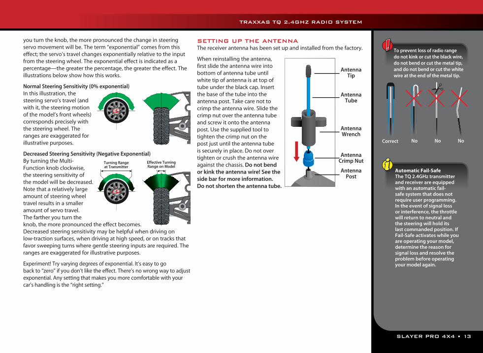
SETTING UP THE ANTENNAThe receiver antenna has been set up and installed from the factory.
When reinstalling the antenna, first slide the antenna wire into bottom of antenna tube until white tip of antenna is at top of tube under the black cap. Insert the base of the tube into the antenna post. Take care not to crimp the antenna wire. Slide the crimp nut over the antenna tube and screw it onto the antenna post. Use the supplied tool to tighten the crimp nut on the post just until the antenna tube is securely in place. Do not over tighten or crush the antenna wire against the chassis. Do not bend or kink the antenna wire! See the side bar for more information. Do not shorten the antenna tube.
Turning Range at Transmitter
Effective Turning Range on Model
Automatic Fail-SafeThe TQ 2.4GHz transmitter and receiver are equipped with an automatic fail-safe system that does not require user programming. In the event of signal loss or interference, the throttle will return to neutral and the steering will hold its last commanded position. If Fail-Safe activates while you are operating your model, determine the reason for signal loss and resolve the problem before operating your model again.
To prevent loss of radio range do not kink or cut the black wire, do not bend or cut the metal tip, and do not bend or cut the white wire at the end of the metal tip.
Correct NoNo No
Antenna Tip
Antenna Tube
Antenna Crimp Nut
Antenna Wrench
Antenna Post
TRAXXAS TQ 2.4GHZ RADIO SYSTEM
14 • SLAYER PRO 4X4
Traxxas strongly discourages changing or modifying any part of the TRX 3.3 Racing Engine. Old tech tips and tricks that may have boosted the power of other engines could seriously diminish the performance of the TRX 3.3 Racing Engine.
There’s more advanced thinking, development and testing in the stock parts of your TRX 3.3 Racing Engine than in many aftermarket manufacturer’s performance parts. The TRX 3.3 Racing Engine is already the most powerful engine in its class and may not benefit from average, low-tech, aftermarket bolt on performance items.
INTRODUCTIONThe TRX® 3.3 Racing Engine is the next generation of TRX nitro power. The larger displacement and advanced porting generate class-leading horsepower while still maintaining the TRX Racing Engine characteristics of broad, linear power delivery and ease of tuning. Focused engineering and rigorous testing have yielded unprecedented power and uncompromising performance that turns ready-to-run into Ready-To-Race®.
The TRX 3.3 Racing Engine takes a total-system approach. Each part of the engine, from the air filter to the exhaust tip, is carefully engineered to work in harmony with other engine components. Each part complements the next, to extract maximum power. The TRX 3.3 Racing Engine is designed to be tolerant of variations in tuning, and to run successfully through a wide range of variable atmospheric conditions such as changes in temperature, humidity, and altitude.
In order to get the longest engine life and keep the TRX 3.3 Racing Engine in top running condition, it is very important to perform regular routine maintenance. The number one cause of premature engine wear and failure is lack of care and maintenance!
BREAK-INThe TRX 3.3 Racing Engine is manufactured to exacting tolerances and requires a specially-designed break-in procedure to accomplish the final precision fitting of the internal engine components. It is very important that you follow the new break-in procedure as closely as possible to achieve the best performance and longest life from your TRX 3.3 Racing Engine. Engine break-in will take between one and two hours. Old style break-in procedures, such as idling the engine on the bench for several tanks of fuel or simply running the engine with a very rich fuel mixture for the first 4 tanks of fuel, will not achieve the best results. Follow the easy steps in this manual.
AIR FILTER MAINTENANCEDirt is the worst enemy to your engine. A clean air filter is absolutely critical for long engine life. Due to the high performance nature of the TRX 3.3 engine, a tremendous amount of vacuum is created to move a large volume of high velocity air through the carburetor. This model is equipped with a two-stage high performance air filter which requires that the pre-filter stage be cleaned and oiled every hour of operation, and the primary filter be cleaned and oiled every 3-4 hours. An extra pre-lubed air filter set has been provided with this model to encourage you to maintain the engine’s air filter.
AFTER-RUN MAINTENANCE Perform after-run maintenance on the engine to prevent corrosion from building up on the internal engine components. The fuel naturally attracts moisture and corrosion can build up very quickly inside the engine if it is not prevented.
A few minutes spent before and after each time you run your model will allow you to enjoy it for a long time to come. Read on for more exciting details about your new engine.
THE TRX 3.3 RACING ENGINE™
SLAYER PRO 4X4 • 15
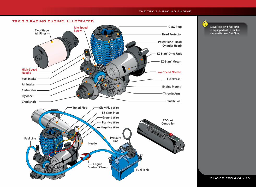
TRX 3.3 RACING ENGINE ILLUSTRATED
Head Protector
PowerTune™ Head (Cylinder Head)
EZ-Start® Drive Unit
EZ-Start® Motor
Engine Mount
Low-Speed Needle
Throttle Arm
Crankshaft
Flywheel
Carburetor
Air Intake
Fuel Intake
High-Speed Needle
Idle SpeedScrew
Clutch Bell
Crankcase
Two-Stage Air Filter
Glow Plug
EZ-Start Plug
Positive Wire
Negative Wire
Fuel Line
Fuel Tank
Tuned Pipe
Header
Pressure Line
Ground Wire
Glow Plug Wire
EZ-StartController
Engine Shut-off Clamp
Slayer Pro 4x4’s fuel tank is equipped with a built-in sintered bronze fuel filter.
THE TRX 3.3 RACING ENGINE
16 • SLAYER PRO 4X4
THE TRX 3.3 RACING ENGINE
TERMS TO KNOWYou’ll find these Nitro R/C engine terms throughout this section of the manual.
.15 - .15 or “15” refers to the displacement of the engine. The TRX 2.5 Racing Engine is .15 cubic inches or 2.5 cubic centimeters (cc). The name “TRX 2.5” is derived from the cc measurement.
.20 - .20 or “20” refers to the size of the engine. The TRX 3.3 is .20 cubic inches or 3.3 cubic centimeters (cc). The name “TRX 3.3” is derived from the cc measurement.
ABC - Abbreviation for aluminum, brass, and chrome. Refers to engine construction that consists of an aluminum piston that slides in a chrome-plated brass sleeve. The TRX 3.3 uses ABC construction.
Air filter - The air filter sits atop the carburetor and prevents harmful dust and dirt from entering the engine. Dirt ingestion is the number one cause of premature engine failure so the engine should never be run without the air filter in place.
BDC - Bottom dead center. The bottom-most position of the engine piston stroke.
Break-in - Break-in is the procedure for running a brand new engine according to specific instructions. This correctly prepares the engine for normal running. The break-in procedure can be different for different makes of engines. Follow the Traxxas directions for break-in exactly.
Carb - Abbreviation for carburetor.Carburetor - The carburetor atomizes (mixes) the fuel with the air
so that the engine can burn it. There are two types of carburetors; slide carbs and barrel carbs. The TRX 3.3 uses the superior slide carburetor design.
Clean-out - Cleaning-out is a condition that occurs when the engine is accelerating and the fuel mixture becomes sufficiently lean to allow the engine to continue into its upper rpm power band. It is usually characterized by a noticeable decrease in blue exhaust smoke and a dramatic increase in engine speed.
Combustion chamber - The combustion chamber is machined into the bottom of the cylinder head. This is where the glow plug ignites the fuel. The shape of the combustion chamber is designed to promote more efficient burning of the fuel.
Connecting rod - The connecting rod transfers the piston motion to the crankshaft. The TRX 3.3 Racing Engine uses a “knife-edged” connecting rod. The aerodynamic, sharpened edges allow it to “slice” through the pressurized air/fuel mixture inside the crankcase.
Crankcase - The engine’s “body” that contains all of the running mechanical components.
Crankshaft - The main shaft of the engine that holds the reciprocating assembly.
Cooling fins - The cooling fins are milled into the cylinder head and crankcase and cause heat to be drawn away from the engine. Heat is removed when it dissipates into the air passing across the cooling fins. It is important to keep the fins clean of dirt and debris for maximum cooling efficiency.
Cylinder head (head) - The finned aluminum part on top of the engine that is responsible for dissipating most of the engine’s heat. The combustion chamber is machined into the bottom of the head.
Dyno - Abbreviation for dynamometer. A precise piece of testing equipment that accurately measures engine power and torque output over the engine’s entire rpm range.
EZ-Start - Traxxas on-board electric starting system. The system consists of a hand held starter control unit and an on-board gearbox with an electric motor to spin the engine.
Fit - Usually refers to the fit of the piston and sleeve. If the fit is tight, the piston will feel very tight at top of the sleeve (top dead center), and the engine will have good sealing and compression. If the fit is loose, compression will be low and both the piston and sleeve should be replaced.
Flame-out - Occurs when the engine stops running at high rpm. Usually the fault of an excessively lean fuel mixture or glow plug failure.
Fuel - (10%, 20%, 33%) The TRX 3.3 must have model engine fuel to run. Traxxas Top Fuel® Power Plus™ is recommended. Fuel is sold in quarts and gallons from hobby dealers. The 10%, 20% and 33% labeling refers to the percentage of nitromethane contained in the fuel.
Fuel mixture - The ratio of fuel to air as determined by the needle settings of the carburetor.
Fuel tubing (fuel line) - The thick silicone tubing that carries fuel from the fuel tank to the carburetor.
Glow plug - The glow plug is located in the cylinder head at the top of the combustion chamber. It contains an element that glows red hot when voltage is applied. When the engine is being started, the heat from the glow plug ignites the fuel mixture and starts the combustion process.
Glow plug driver - This tool clips onto the glow plug and supplies the required voltage to light the glow plug element. It is also called an igniter. EZ-Start equipped engines do not require this separate tool.
Header - The aluminum tube that connects the exhaust system to the engine exhaust port. The length and diameter of the header must be carefully selected to extract the most power from the engine.
SLAYER PRO 4X4 • 17
THE TRX 3.3 RACING ENGINE
High-speed needle (HSN) - Adjusts the carburetors fuel/air mixture at high throttle openings.
Idle speed - The speed (rpm) the engine runs at when the transmitter’s throttle trigger is at neutral.
Idle speed screw (ISS) - Located on the carburetor body. This screw adjusts the idle rpm of the engine.
Lean - A running condition where the engine is not getting enough fuel (for the available air). Symptoms include engine overheating, or the engine runs for a short time and then stalls, particularly at high speed. This is a dangerous condition that should be corrected immediately or it can ruin your engine.
Leaning the mixture - Turning either the high-speed and/or low-speed needle(s) clockwise to decrease the amount of fuel the engine receives.
Low-speed needle (LSN) - Needle valve that controls the fuel mixture at low throttle openings.
Needle valve - Valve consisting of a tapered needle that closes against a corresponding seat to regulate fuel flow.
Nitro - Abbreviation for nitromethane, a component of model engine fuel that improves fuel combustion and power output. Nitro also refers to a class of R/C powered by model engines instead of electric.
Nitro content - The amount of nitromethane used in the fuel. Usually measured as a percentage of the total fuel volume. Traxxas engines are optimized to use 10-20% nitro. 33% nitro may be used for racing.
Nitromethane - Nitromethane is a component in the fuel that increases power from the combustion process up to a point. Engines are generally optimized to use a range of nitro content for the best power.
O-ring - Rubber “O”-shaped ring used as a sealing gasket. Pipe - Abbreviation for the tuned exhaust pipe on a nitro engine.
See “Tuned Pipe”.Piston - The piston is the internal engine part that is attached to
the upper end of the connecting rod and moves up and down in the cylinder sleeve. The precise fit between the piston and the sleeve creates a seal that allows the engine to have the required compression for combustion.
Port - Ports are openings in the sleeve that allow atomized fuel to enter the combustion chamber and burned exhaust gases to exit. The shape and location of the ports are a large factor in controlling the engine timing and power output.
Pre-filter - The outer air filter element in a two-stage air filter. This provides the first level of air filtration for the engine. The majority
of dirt and debris will be stopped by this filter. Clean, re-oil, and replace this filter after every hour of run time. Always use both the pre-filter and primary filter.
Primary filter - The inner air filter element in a two-stage air filter. This provides a second level of air filtration after the pre-filter removes the majority of dirt and debris. Clean, re-oil, and replace this filter after every 3 - 4 hours of run time. Always use both the pre-filter and primary filter.
Priming - Manually causing fuel to move from the fuel tank up to the carburetor. This is sometimes necessary after the engine has been sitting for a long period of time and all of the fuel has drained back to the tank. On a Traxxas model this is done by holding your finger over the exhaust tip for one or two seconds while the engine is starting.
Punch - A term that refers to how quickly the model responds to throttle input or how quickly it accelerates.
Rich - A running condition where the engine is getting too much fuel for the available air. It is better to run an engine slightly rich to increase engine life. Excessively rich mixtures cause the engine to have sluggish performance with exaggerated blue smoke and unburned fuel coming from the exhaust.
rpm - Abbreviation for revolutions per minute (how many times the engine crankshaft spins in a minute).
Sleeve - Internal engine part that contains the piston. The precise fit between the sleeve and the piston creates a seal that allows engine to have the required compression for combustion. The sleeve in a TRX engine is made of brass and is then hard-chrome plated.
Slide carburetor - The throttle on a slide carburetor closes and opens by sliding a barrel in and out of the carburetor body. This type of carburetor is preferred for performance use because it provides a less restrictive “straight-through” air path than the barrel carburetor design.
Stall - When the engine stops running, usually due to an incorrect fuel mixture setting or running out of fuel.
TDC - Top dead center. The top-most position of the engine piston stroke.
Tuned pipe - The tuned exhaust pipe usually consists of a specially-shaped metal or composite chamber with baffles that is designed to enhance the power output of the engine.
Wear-in - Fitment process that occurs during engine break-in where internal engine parts develop an even more precise matched fit through actual use under controlled circumstances.
WOT - Abbreviation for wide-open throttle.
18 • SLAYER PRO 4X4
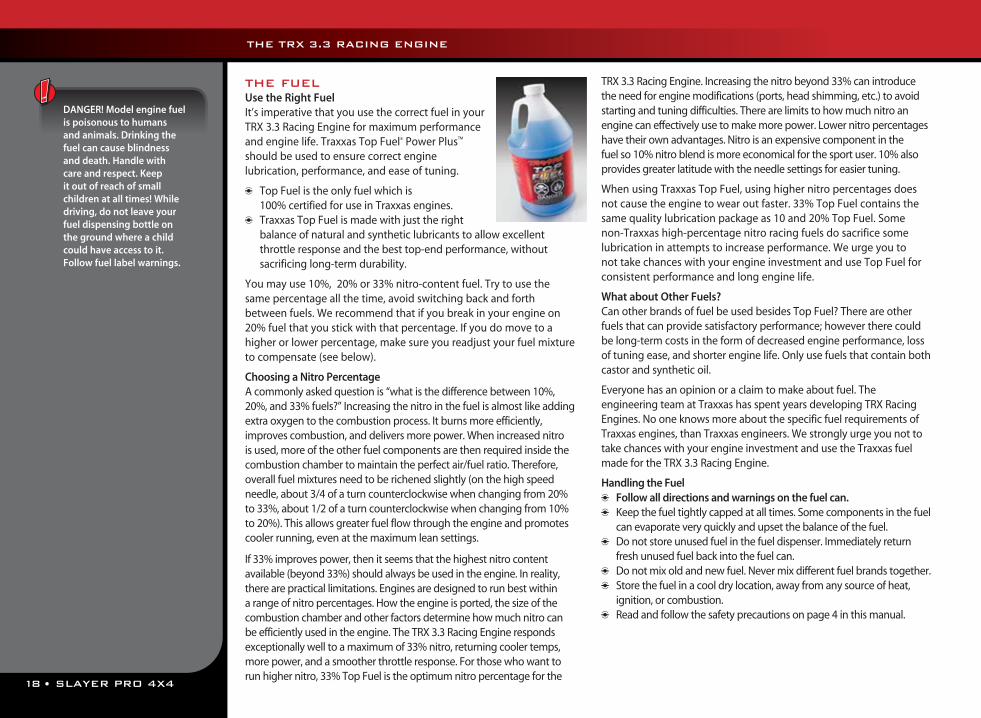
DANGER! Model engine fuel is poisonous to humans and animals. Drinking the fuel can cause blindness and death. Handle with care and respect. Keep it out of reach of small children at all times! While driving, do not leave your fuel dispensing bottle on the ground where a child could have access to it. Follow fuel label warnings.
THE FUEL Use the Right FuelIt’s imperative that you use the correct fuel in your TRX 3.3 Racing Engine for maximum performance and engine life. Traxxas Top Fuel® Power Plus™ should be used to ensure correct engine lubrication, performance, and ease of tuning.
Top Fuel is the only fuel which is 100% certified for use in Traxxas engines.
Traxxas Top Fuel is made with just the right balance of natural and synthetic lubricants to allow excellent throttle response and the best top-end performance, without sacrificing long-term durability.
You may use 10%, 20% or 33% nitro-content fuel. Try to use the same percentage all the time, avoid switching back and forth between fuels. We recommend that if you break in your engine on 20% fuel that you stick with that percentage. If you do move to a higher or lower percentage, make sure you readjust your fuel mixture to compensate (see below).
Choosing a Nitro PercentageA commonly asked question is “what is the difference between 10%, 20%, and 33% fuels?” Increasing the nitro in the fuel is almost like adding extra oxygen to the combustion process. It burns more efficiently, improves combustion, and delivers more power. When increased nitro is used, more of the other fuel components are then required inside the combustion chamber to maintain the perfect air/fuel ratio. Therefore, overall fuel mixtures need to be richened slightly (on the high speed needle, about 3/4 of a turn counterclockwise when changing from 20% to 33%, about 1/2 of a turn counterclockwise when changing from 10% to 20%). This allows greater fuel flow through the engine and promotes cooler running, even at the maximum lean settings.
If 33% improves power, then it seems that the highest nitro content available (beyond 33%) should always be used in the engine. In reality, there are practical limitations. Engines are designed to run best within a range of nitro percentages. How the engine is ported, the size of the combustion chamber and other factors determine how much nitro can be efficiently used in the engine. The TRX 3.3 Racing Engine responds exceptionally well to a maximum of 33% nitro, returning cooler temps, more power, and a smoother throttle response. For those who want to run higher nitro, 33% Top Fuel is the optimum nitro percentage for the
TRX 3.3 Racing Engine. Increasing the nitro beyond 33% can introduce the need for engine modifications (ports, head shimming, etc.) to avoid starting and tuning difficulties. There are limits to how much nitro an engine can effectively use to make more power. Lower nitro percentages have their own advantages. Nitro is an expensive component in the fuel so 10% nitro blend is more economical for the sport user. 10% also provides greater latitude with the needle settings for easier tuning.
When using Traxxas Top Fuel, using higher nitro percentages does not cause the engine to wear out faster. 33% Top Fuel contains the same quality lubrication package as 10 and 20% Top Fuel. Some non-Traxxas high-percentage nitro racing fuels do sacrifice some lubrication in attempts to increase performance. We urge you to not take chances with your engine investment and use Top Fuel for consistent performance and long engine life.
What about Other Fuels?Can other brands of fuel be used besides Top Fuel? There are other fuels that can provide satisfactory performance; however there could be long-term costs in the form of decreased engine performance, loss of tuning ease, and shorter engine life. Only use fuels that contain both castor and synthetic oil.
Everyone has an opinion or a claim to make about fuel. The engineering team at Traxxas has spent years developing TRX Racing Engines. No one knows more about the specific fuel requirements of Traxxas engines, than Traxxas engineers. We strongly urge you not to take chances with your engine investment and use the Traxxas fuel made for the TRX 3.3 Racing Engine.
Handling the Fuel Follow all directions and warnings on the fuel can. Keep the fuel tightly capped at all times. Some components in the fuel
can evaporate very quickly and upset the balance of the fuel. Do not store unused fuel in the fuel dispenser. Immediately return
fresh unused fuel back into the fuel can. Do not mix old and new fuel. Never mix different fuel brands together. Store the fuel in a cool dry location, away from any source of heat,
ignition, or combustion. Read and follow the safety precautions on page 4 in this manual.
THE TRX 3.3 RACING ENGINE
SLAYER PRO 4X4 • 19
Filling the Fuel TankUse a fuel dispensing bottle (Traxxas Top Fueler, part #5001) to put fuel into Slayer Pro 4x4’s fuel tank. To fill the fuel bottle, squeeze the air out, insert the dispenser tip into the fuel can, and release your grip on the bottle. As the bottle expands, fuel will be drawn into it.
To fill your model, pull up on the fuel cap handle, insert the tip of the fuel bottle, and squeeze to dispense the fuel.
THE AIR FILTERThe TRX 3.3 Racing Engine in this model is equipped with a specially designed two-stage air filter to deliver maximum filtering efficiency and performance while protecting your engine from dust and dirt during extended operating conditions. Use only the supplied filter. You will not improve engine performance by switching to an aftermarket filter, and you may risk engine damage due to poor filtration.
The two-stage TRX Racing Filter consists of the following components:1. A rubber filter Base2. A 3-piece plastic housing 3. A “pre-filter” element4. A “primary” filter element
You must clean the outer pre-filter after every hour of run time, even if the filter looks clean. The primary filter element inside must be cleaned after 3-4 hours of run time. These intervals include the break-in time. Clean your air filter after break-in. Dust (which is often too fine to see) and dirt constantly move through the filter anytime the engine is running. Even if you can’t see dirt on the filter, it is present inside the foam after any amount of run time. If you exceed the recommended cleaning intervals, your engine will be damaged. Engine damage or wear due to dirt ingestion is easy to detect, and one of the top causes of premature engine failure.
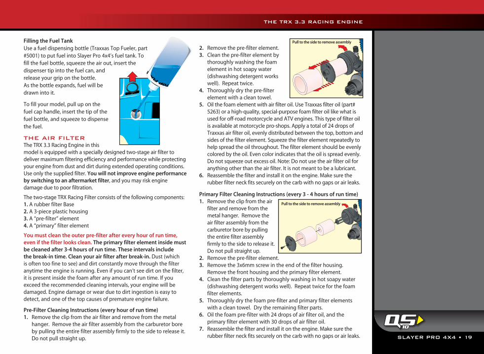
Pre-Filter Cleaning Instructions (every hour of run time)1. Remove the clip from the air filter and remove from the metal
hanger. Remove the air filter assembly from the carburetor bore by pulling the entire filter assembly firmly to the side to release it. Do not pull straight up.
2. Remove the pre-filter element.3. Clean the pre-filter element by
thoroughly washing the foam element in hot soapy water (dishwashing detergent works well). Repeat twice.
4. Thoroughly dry the pre-filter element with a clean towel.
5. Oil the foam element with air filter oil. Use Traxxas filter oil (part# 5263) or a high-quality, special-purpose foam filter oil like what is used for off-road motorcycle and ATV engines. This type of filter oil is available at motorcycle pro-shops. Apply a total of 24 drops of Traxxas air filter oil, evenly distributed between the top, bottom and sides of the filter element. Squeeze the filter element repeatedly to help spread the oil throughout. The filter element should be evenly colored by the oil. Even color indicates that the oil is spread evenly. Do not squeeze out excess oil. Note: Do not use the air filter oil for anything other than the air filter. It is not meant to be a lubricant.
6. Reassemble the filter and install it on the engine. Make sure the rubber filter neck fits securely on the carb with no gaps or air leaks.
Primary Filter Cleaning Instructions (every 3 - 4 hours of run time)1. Remove the clip from the air
filter and remove from the metal hanger. Remove the air filter assembly from the carburetor bore by pulling the entire filter assembly firmly to the side to release it. Do not pull straight up.
2. Remove the pre-filter element.3. Remove the 3x6mm screw in the end of the filter housing.
Remove the front housing and the primary filter element.4. Clean the filter parts by thoroughly washing in hot soapy water
(dishwashing detergent works well). Repeat twice for the foam filter elements.
5. Thoroughly dry the foam pre-filter and primary filter elements with a clean towel. Dry the remaining filter parts.
6. Oil the foam pre-filter with 24 drops of air filter oil, and the primary filter element with 30 drops of air filter oil.
7. Reassemble the filter and install it on the engine. Make sure the rubber filter neck fits securely on the carb with no gaps or air leaks.
Pull to the side to remove assembly
Pull to the side to remove assembly
THE TRX 3.3 RACING ENGINE
10
20 • SLAYER PRO 4X4
See page 27 for more information on how air density affects engine tuning.
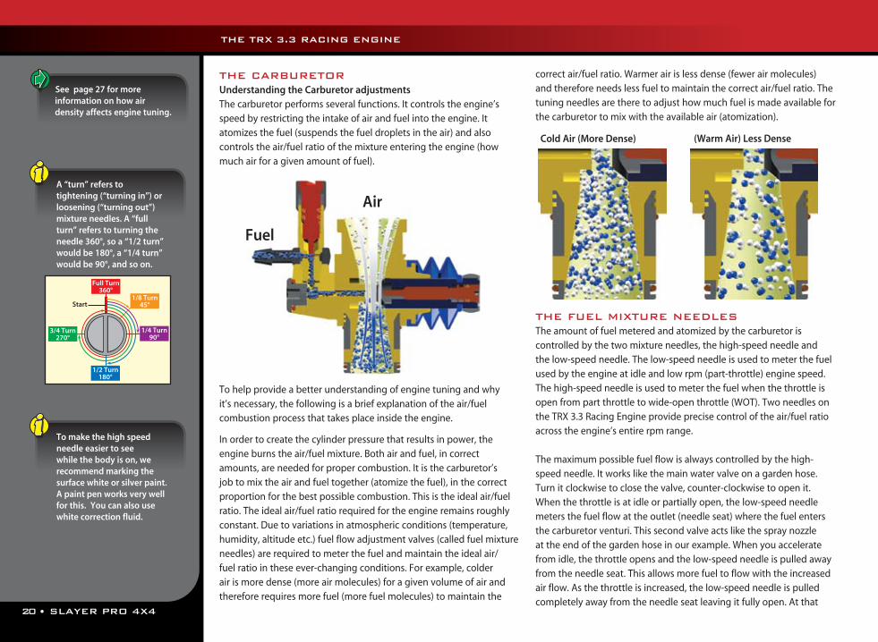
THE CARBURETORUnderstanding the Carburetor adjustmentsThe carburetor performs several functions. It controls the engine’s speed by restricting the intake of air and fuel into the engine. It atomizes the fuel (suspends the fuel droplets in the air) and also controls the air/fuel ratio of the mixture entering the engine (how much air for a given amount of fuel).
To help provide a better understanding of engine tuning and why it’s necessary, the following is a brief explanation of the air/fuel combustion process that takes place inside the engine.
In order to create the cylinder pressure that results in power, the engine burns the air/fuel mixture. Both air and fuel, in correct amounts, are needed for proper combustion. It is the carburetor’s job to mix the air and fuel together (atomize the fuel), in the correct proportion for the best possible combustion. This is the ideal air/fuel ratio. The ideal air/fuel ratio required for the engine remains roughly constant. Due to variations in atmospheric conditions (temperature, humidity, altitude etc.) fuel flow adjustment valves (called fuel mixture needles) are required to meter the fuel and maintain the ideal air/fuel ratio in these ever-changing conditions. For example, colder air is more dense (more air molecules) for a given volume of air and therefore requires more fuel (more fuel molecules) to maintain the
correct air/fuel ratio. Warmer air is less dense (fewer air molecules) and therefore needs less fuel to maintain the correct air/fuel ratio. The tuning needles are there to adjust how much fuel is made available for the carburetor to mix with the available air (atomization).
THE FUEL MIXTURE NEEDLESThe amount of fuel metered and atomized by the carburetor is controlled by the two mixture needles, the high-speed needle and the low-speed needle. The low-speed needle is used to meter the fuel used by the engine at idle and low rpm (part-throttle) engine speed. The high-speed needle is used to meter the fuel when the throttle is open from part throttle to wide-open throttle (WOT). Two needles on the TRX 3.3 Racing Engine provide precise control of the air/fuel ratio across the engine’s entire rpm range.
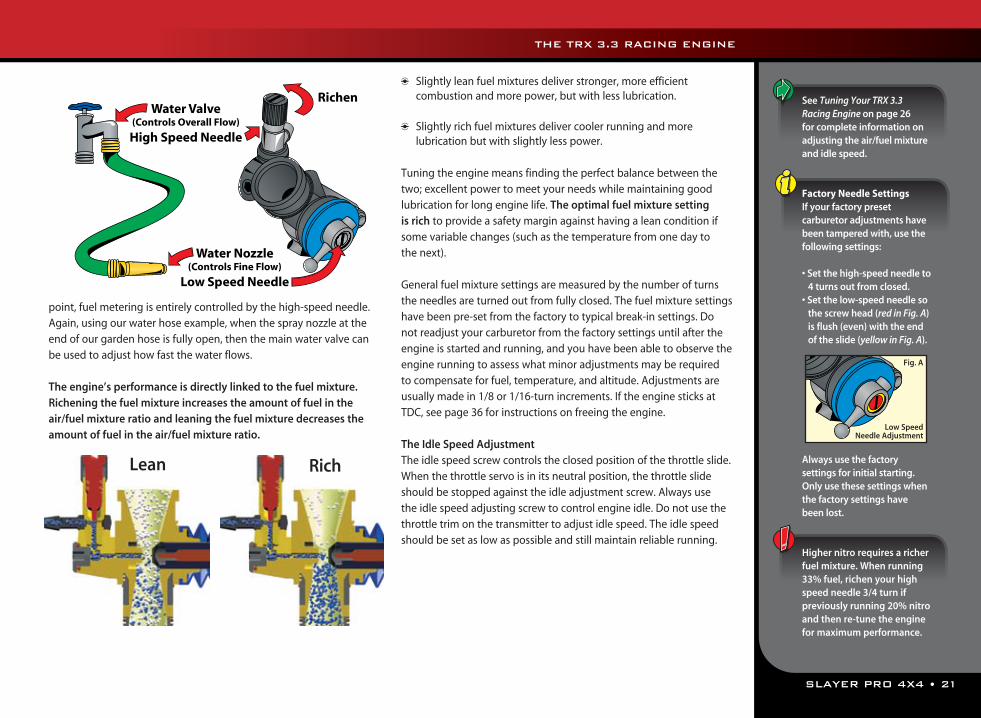
The maximum possible fuel flow is always controlled by the high-speed needle. It works like the main water valve on a garden hose. Turn it clockwise to close the valve, counter-clockwise to open it. When the throttle is at idle or partially open, the low-speed needle meters the fuel flow at the outlet (needle seat) where the fuel enters the carburetor venturi. This second valve acts like the spray nozzle at the end of the garden hose in our example. When you accelerate from idle, the throttle opens and the low-speed needle is pulled away from the needle seat. This allows more fuel to flow with the increased air flow. As the throttle is increased, the low-speed needle is pulled completely away from the needle seat leaving it fully open. At that
Air
Fuel
Cold Air (More Dense) (Warm Air) Less Dense
Start1/8 Turn
45°
Full Turn360°
1/2 Turn180°
1/4 Turn90°
3/4 Turn270°
A “turn” refers to tightening (“turning in”) or loosening (“turning out”) mixture needles. A “full turn” refers to turning the needle 360°, so a “1/2 turn” would be 180°, a “1/4 turn” would be 90°, and so on.
To make the high speed needle easier to see while the body is on, we recommend marking the surface white or silver paint. A paint pen works very well for this. You can also use white correction fluid.
THE TRX 3.3 RACING ENGINE
SLAYER PRO 4X4 • 21
point, fuel metering is entirely controlled by the high-speed needle. Again, using our water hose example, when the spray nozzle at the end of our garden hose is fully open, then the main water valve can be used to adjust how fast the water flows.
The engine’s performance is directly linked to the fuel mixture. Richening the fuel mixture increases the amount of fuel in the air/fuel mixture ratio and leaning the fuel mixture decreases the amount of fuel in the air/fuel mixture ratio.
Slightly lean fuel mixtures deliver stronger, more efficient combustion and more power, but with less lubrication.
Slightly rich fuel mixtures deliver cooler running and more lubrication but with slightly less power.
Tuning the engine means finding the perfect balance between the two; excellent power to meet your needs while maintaining good lubrication for long engine life. The optimal fuel mixture setting is rich to provide a safety margin against having a lean condition if some variable changes (such as the temperature from one day to the next).
General fuel mixture settings are measured by the number of turns the needles are turned out from fully closed. The fuel mixture settings have been pre-set from the factory to typical break-in settings. Do not readjust your carburetor from the factory settings until after the engine is started and running, and you have been able to observe the engine running to assess what minor adjustments may be required to compensate for fuel, temperature, and altitude. Adjustments are usually made in 1/8 or 1/16-turn increments. If the engine sticks at TDC, see page 36 for instructions on freeing the engine.
The Idle Speed AdjustmentThe idle speed screw controls the closed position of the throttle slide. When the throttle servo is in its neutral position, the throttle slide should be stopped against the idle adjustment screw. Always use the idle speed adjusting screw to control engine idle. Do not use the throttle trim on the transmitter to adjust idle speed. The idle speed should be set as low as possible and still maintain reliable running.
Water Valve(Controls Overall Flow)
High Speed Needle
Water Nozzle(Controls Fine Flow)
Low Speed Needle
Richen
Lean Rich
See Tuning Your TRX 3.3 Racing Engine on page 26 for complete information on adjusting the air/fuel mixture and idle speed.
Factory Needle SettingsIf your factory preset carburetor adjustments have been tampered with, use the following settings:
• Set the high-speed needle to 4 turns out from closed.
• Set the low-speed needle so the screw head (red in Fig. A) is flush (even) with the end of the slide (yellow in Fig. A).
Always use the factory settings for initial starting. Only use these settings when the factory settings have been lost.
Higher nitro requires a richer fuel mixture. When running 33% fuel, richen your high speed needle 3/4 turn if previously running 20% nitro and then re-tune the engine for maximum performance.
Low Speed Needle Adjustment
Fig. A
THE TRX 3.3 RACING ENGINE
22 • SLAYER PRO 4X4
Using Other ChargersAnother convenient option for charging the included battery is an AC peak-detecting charger that plugs directly into an AC wall outlet, such as the TRX Power Charger, Part #3030X. It contains special peak-detection circuitry that automatically shuts the charger off when the battery is fully charged.
Caution: Never use a 15-minute timed charger to recharge your model’s battery packs. Overcharging may result, causing damage to the battery packs.
THE TRX 3.3 RACING ENGINE
2,6,11
The Traxxas EZ-Start brings the convenience of push-button electric engine starting to your Slayer Pro 4x4. The EZ-Start consists of a hand-held control unit and an on-board motorized starter.
Power for the EZ-Start system comes from a 7.2-volt rechargeable battery pack installed in the hand-held control unit.
The engine glow plug is heated automatically by the EZ-Start system, eliminating the need to keep up with a separate glow plug igniter.
The voltage to the glow plug is kept constant, regardless of the load placed on the starter by the starter motor.
The “Glow Plug” LED (light emitting diode) on the control unit indicates the condition of the glow plug.
The “Motor” LED indicates the status of the EZ-Start electric starter motor. The cush drive mechanism in the drive unit prevents damage to the
gears caused by engine kickback. Smart Start™ protection circuitry prevents damage to the motor by cutting
power if the load on the motor or other electronics exceeds safe limits.
Charging the EZ-Start BatteryThe included charger can be used to charge the included EZ-Start battery pack.
1. Plug the charger into the wall. The LED on the charger should glow green.
2. Connect the included EZ-Start battery pack to the charger output cord. The LED will glow red indicating the battery is charging.
3. The battery should charge for approximately 4 ½ hours. The LED will turn green when the battery is fully charged.
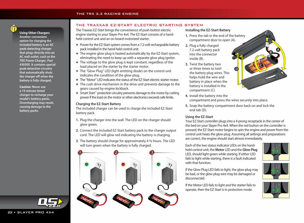
Installing the EZ-Start Battery
1. Press the tab in the end of the battery compartment door to open (A).
2. Plug a fully charged 7.2-volt battery pack into the connector inside (B).
3. Twist the battery two or three times to twirl the battery plug wires. This helps hold the wire and battery in place when the battery is installed in the compartment (C).
4. Install the battery into the compartment and press the wires securely into place.
5. Snap the battery compartment door back on and lock the end tab (D).
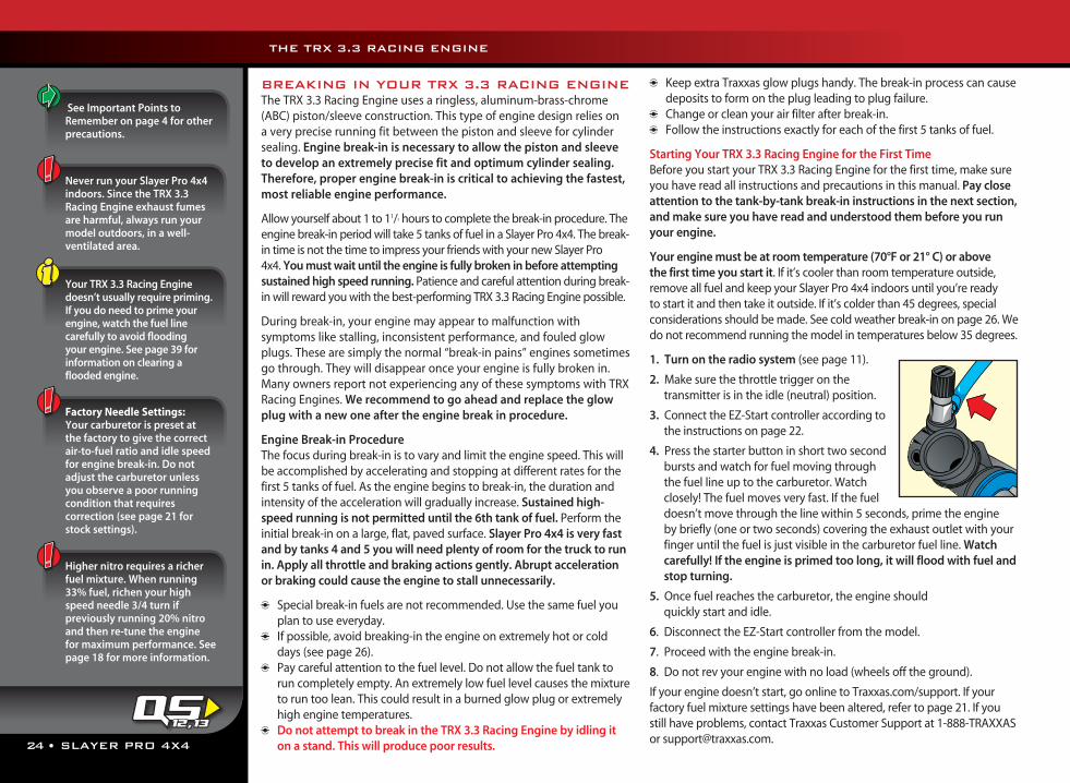
Using the EZ-StartYour EZ-Start controller plugs into a 4-prong receptacle in the center of the bed on your Slayer Pro 4x4. When the red button on the controller is pressed, the EZ-Start motor begins to spin the engine and power from the control unit heats the glow plug. Assuming all settings and preparations are correct, the engine should start almost immediately.
Each of the two status indicator LEDs on the hand-held control unit, the Motor LED and the Glow Plug LED, should light green while starting. If either LED fails to light while starting, there is a fault indicated with that function.
If the Glow Plug LED fails to light, the glow plug may be bad, or the glow plug wire may be damaged or disconnected.
If the Motor LED fails to light and the starter fails to operate, then the EZ-Start is in protection mode.
THE TRAXXAS EZ-START ELECTRIC STARTING SYSTEM
AB
CD
Mo
tor
Glo
w
Plu
g
Mo
tor
Glo
w
Plu
g
Mo
tor
Glo
w
Plu
g
Mo
tor
Glo
w
Plu
g
Mo
tor
Glo
w
Plu
g
Mo
tor
Glo
w
Plu
g
Mo
tor
Glo
w
Plu
g
Mo
tor
Glo
w
Plu
g
Mo
tor
Glo
w
Plu
g
Mo
tor
Glo
w
Plu
g
Mo
tor
Glo
w
Plu
g
Mo
tor
Glo
w
Plu
g
Mo
tor
Glo
w
Plu
g
Mo
tor
Glo
w
Plu
g
Mo
tor
Glo
w
Plu
g
Mo
tor
Glo
w
Plu
g
Mo
tor
Glo
w
Plu
g
Mo
tor
Glo
w
Plu
g
Mo
tor
Glo
w
Plu
g
Mo
tor
Glo
w
Plu
g
Mo
tor
Glo
w
Plu
g
Mo
tor
Glo
w
Plu
g
Mo
tor
Glo
w
Plu
g
Mo
tor
Glo
w
Plu
g
Mo
tor
Glo
w
Plu
g
Mo
tor
Glo
w
Plu
g
Mo
tor
Glo
w
Plu
g
2 31
SLAYER PRO 4X4 • 23
When the EZ-Start controller is in protection mode, wait at least three minutes before attempting to start the engine, to give the starter motor time to cool.
It’s normal for your EZ-Start controller to become warm after repeated use.
THE TRX 3.3 RACING ENGINE
Protection ModeThe EZ-Start uses Smart Start™ technology to monitor the condition of the system and detect failures. The controller monitors the load being placed on the EZ-Start motor. If the load becomes excessive, the system shuts off power to the motor to prevent costly damage to the motor and the controller. This may occur, for example, if the engine floods with fuel during starting. The starter spins at first but when excessive fuel in the combustion chamber begins to lock up the engine, the starter motor slows under the heavier load. This causes the protection circuit to shut off the power to the motor. Allow at least 3 minutes for the starter motor to cool and the circuit to automatically reset before continuing. Use the time to find and eliminate the condition that caused the excessive load on the starter motor.
Use a Strong Starter Battery A weak starter battery, or one that has not been fully charged, may not deliver enough power to crank the engine over at the appropriate rpm to keep the piston from sticking at top dead center (TDC). A new engine will typically have a tight fit between the piston and the top of the sleeve. This is a tapered fit, and a tight piston sleeve fit on initial startup is desirable for those who want the best-performing engine. Make sure you are using a good quality battery pack that is fully charged (new batteries usually require several charge cycles to reach peak voltage and full capacity). This is especially important with a new engine that needs to be broken in. If the engine sticks at TDC, see page 34 for instructions on freeing the engine.
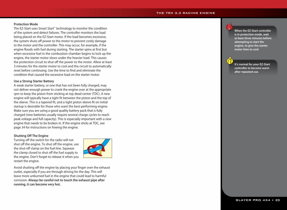
Shutting Off The EngineTurning off the switch for the radio will not shut off the engine. To shut off the engine, use the shut-off clamp on the fuel line. Squeeze the clamp closed to shut off the fuel supply to the engine. Don’t forget to release it when you restart the engine.
Avoid shutting off the engine by placing your finger over the exhaust outlet, especially if you are through driving for the day. This will leave more unburned fuel in the engine that could lead to harmful corrosion. Always be careful not to touch the exhaust pipe after running, it can become very hot.
24 • SLAYER PRO 4X4
See Important Points to Remember on page 4 for other precautions.
BREAKING IN YOUR TRX 3.3 RACING ENGINEThe TRX 3.3 Racing Engine uses a ringless, aluminum-brass-chrome (ABC) piston/sleeve construction. This type of engine design relies on a very precise running fit between the piston and sleeve for cylinder sealing. Engine break-in is necessary to allow the piston and sleeve to develop an extremely precise fit and optimum cylinder sealing. Therefore, proper engine break-in is critical to achieving the fastest, most reliable engine performance.
Allow yourself about 1 to 11/2 hours to complete the break-in procedure. The engine break-in period will take 5 tanks of fuel in a Slayer Pro 4x4. The break-in time is not the time to impress your friends with your new Slayer Pro 4x4. You must wait until the engine is fully broken in before attempting sustained high speed running. Patience and careful attention during break-in will reward you with the best-performing TRX 3.3 Racing Engine possible.
During break-in, your engine may appear to malfunction with symptoms like stalling, inconsistent performance, and fouled glow plugs. These are simply the normal “break-in pains” engines sometimes go through. They will disappear once your engine is fully broken in. Many owners report not experiencing any of these symptoms with TRX Racing Engines. We recommend to go ahead and replace the glow plug with a new one after the engine break in procedure.
Engine Break-in ProcedureThe focus during break-in is to vary and limit the engine speed. This will be accomplished by accelerating and stopping at different rates for the first 5 tanks of fuel. As the engine begins to break-in, the duration and intensity of the acceleration will gradually increase. Sustained high-speed running is not permitted until the 6th tank of fuel. Perform the initial break-in on a large, flat, paved surface. Slayer Pro 4x4 is very fast and by tanks 4 and 5 you will need plenty of room for the truck to run in. Apply all throttle and braking actions gently. Abrupt acceleration or braking could cause the engine to stall unnecessarily.
Special break-in fuels are not recommended. Use the same fuel you plan to use everyday.
If possible, avoid breaking-in the engine on extremely hot or cold days (see page 26).
Pay careful attention to the fuel level. Do not allow the fuel tank to run completely empty. An extremely low fuel level causes the mixture to run too lean. This could result in a burned glow plug or extremely high engine temperatures.
Do not attempt to break in the TRX 3.3 Racing Engine by idling it on a stand. This will produce poor results.
Keep extra Traxxas glow plugs handy. The break-in process can cause deposits to form on the plug leading to plug failure.
Change or clean your air filter after break-in. Follow the instructions exactly for each of the first 5 tanks of fuel.
Starting Your TRX 3.3 Racing Engine for the First TimeBefore you start your TRX 3.3 Racing Engine for the first time, make sure you have read all instructions and precautions in this manual. Pay close attention to the tank-by-tank break-in instructions in the next section, and make sure you have read and understood them before you run your engine.
Your engine must be at room temperature (70°F or 21° C) or above the first time you start it. If it’s cooler than room temperature outside, remove all fuel and keep your Slayer Pro 4x4 indoors until you’re ready to start it and then take it outside. If it’s colder than 45 degrees, special considerations should be made. See cold weather break-in on page 26. We do not recommend running the model in temperatures below 35 degrees.
1. Turn on the radio system (see page 11).
2. Make sure the throttle trigger on the transmitter is in the idle (neutral) position.
3. Connect the EZ-Start controller according to the instructions on page 22.
4. Press the starter button in short two second bursts and watch for fuel moving through the fuel line up to the carburetor. Watch closely! The fuel moves very fast. If the fuel doesn’t move through the line within 5 seconds, prime the engine by briefly (one or two seconds) covering the exhaust outlet with your finger until the fuel is just visible in the carburetor fuel line. Watch carefully! If the engine is primed too long, it will flood with fuel and stop turning.
5. Once fuel reaches the carburetor, the engine should quickly start and idle.
6. Disconnect the EZ-Start controller from the model.
7. Proceed with the engine break-in.
8. Do not rev your engine with no load (wheels off the ground).
If your engine doesn’t start, go online to Traxxas.com/support. If your factory fuel mixture settings have been altered, refer to page 21. If you still have problems, contact Traxxas Customer Support at 1-888-TRAXXAS or [email protected].
Never run your Slayer Pro 4x4 indoors. Since the TRX 3.3 Racing Engine exhaust fumes are harmful, always run your model outdoors, in a well-ventilated area.
Your TRX 3.3 Racing Engine doesn’t usually require priming. If you do need to prime your engine, watch the fuel line carefully to avoid flooding your engine. See page 39 for information on clearing a flooded engine.
Factory Needle Settings:Your carburetor is preset at the factory to give the correct air-to-fuel ratio and idle speed for engine break-in. Do not adjust the carburetor unless you observe a poor running condition that requires correction (see page 21 for stock settings).
Higher nitro requires a richer fuel mixture. When running 33% fuel, richen your high speed needle 3/4 turn if previously running 20% nitro and then re-tune the engine for maximum performance. See page 18 for more information.
THE TRX 3.3 RACING ENGINE
12, 13
SLAYER PRO 4X4 • 25
TANK THROTTLE TIME COOL BODY NOTES
1 1/4 2 seconds 15 minutes Off Apply throttle gradually.
2 1/2 2 seconds 15 minutes On Apply throttle gradually.
3 1/2 3 seconds - On Reduce idle speed if necessary.
4 Full 3 seconds - On Do not allow shifting to high gear.
5 Full 5 seconds - On Accelerate over 3 second count, hold for 2 seconds.
Tank 11. Drive the model with the body off.2. Driving procedure: Gently pull the throttle trigger to 1/4 throttle
over a 2-second count. Then gently apply the brake to stop. Count the two seconds out while accelerating: one thousand one, one thousand two, and then stop. Operate the throttle trigger as smoothly as you can. Repeat this starting and stopping procedure until the first tank of fuel is nearly empty.
3. Look for thick blue smoke exiting the exhaust outlet. If there is no smoke, richen the high-speed needle 1/4 turn, by turning the needle counterclockwise.
4. When the fuel tank is nearly empty, shut off the engine by pinching the fuel line connected to the carburetor (use the installed clamp).
5. Let the engine cool for 15 minutes.Note: If at any point the engine cuts out or stalls during gentle acceleration, richen the high-speed needle 1/4 turn by turning the needle counterclockwise.
Tank 21. From tank 2 forward, Slayer Pro 4x4 should be driven with the body on.2. Driving procedure: Gently pull the throttle trigger to 1/2 throttle
over a 2-second count. Then gently apply the brake to stop. Count the two seconds out while accelerating: one thousand one, one thousand two, and then stop. Repeat this starting and stopping procedure until the second tank of fuel is nearly empty.
3. When the fuel tank is nearly empty, shut off the engine and let it cool for 15 minutes.
Tank 31. Driving procedure: Gently pull the throttle trigger to 1/2 throttle
over a 3-second count. Then gently apply the brake to stop. Count the three seconds out while accelerating: one thousand one, one thousand two, one thousand three, and then stop. Repeat this starting and stopping procedure until the third tank of fuel is nearly empty.
2. As the engine loosens, the idle speed may increase and cause the model to try to creep forward when stopped. Reduce the idle speed by turning the idle adjustment (see page 15) on the carburetor counterclockwise.
3. When the fuel tank is nearly empty, shut off the engine and refuel. From here on, you do not need to let the engine cool between tanks.
Tank 41. Driving procedure: Gently pull the throttle trigger to full throttle
over a 3-second count. Then gently apply the brake to stop. Count the three seconds out while accelerating: one thousand one, one thousand two, one thousand three, and then stop. Repeat this starting and stopping procedure until the fourth tank of fuel is nearly empty.
2. Apply the throttle gradually! Your finger should not reach full throttle until the end of the three-second count. Slayer Pro 4x4 may try to shift into second gear. If it does, reduce the throttle input. Do not let Slayer Pro 4x4 shift out of first gear.
3. Keep your driving smooth and consistent.4. When the fuel tank is nearly empty, shut off the engine and refuel.
Tank 51. Driving procedure: Gently pull the throttle trigger to full throttle
over a 3-second count, hold for 2 more seconds, and then gently apply the brake to stop. Count the five seconds out while accelerating. Repeat this starting and stopping procedure until the fifth tank of fuel is nearly empty.
2. The model should now be shifting into second gear. If it is not, try turning the high-speed needle clockwise 1/8 turn to lean the fuel mixture slightly and test for shifting.
3. When the fuel tank is nearly empty, shut off the engine and refuel.
Tank 6STOP! Clean your air filter before you proceed. Refer to the instructions on page 19. During the sixth tank of fuel, the engine can be tuned for general performance use. Proceed to the next section in this manual.
High Altitude Operation:If you live in a high altitude region (5000 or more feet above sea level), the lower air density may require you to lean your high-speed fuel mixture slightly from the factory break in settings. Try this if you are experiencing difficult starting or extremely sluggish engine performance at high altitude.
As you gain experience in the hobby, you may discover that many people have differing opinions on what is the proper procedure to break-in a model engine. Only use the Traxxas break-in procedure. Other break-in procedures could result in a weak, damaged, or otherwise poor performing engine. The procedure outlined here was extensively tested and proven to yield better performing engines than other “common” break-in methods. Even if you have years of experience using model engines, please do not ignore this caution!
THE TRX 3.3 RACING ENGINE
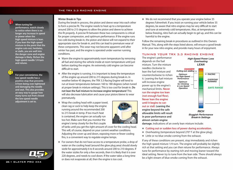
26 • SLAYER PRO 4X4
Winter Break-in TipsDuring the break-in process, the piston and sleeve wear into each other to form a precise fit. The engine needs to heat up to a temperature around 200 to 215 degrees to allow the piston and sleeve to achieve this fit properly. A precise fit between these two components is critical for proper compression, and optimum performance. If the engine runs too cold during break-in, the piston and sleeve will not expand to their appropriate sizes for break-in, and this can lead to premature wear of these components. This wear may not become apparent until after winter has past, and the engine is operated under warmer running conditions.
Warm the engine to approximately room temperature by removing all fuel and storing the vehicle inside at room temperature until just before starting the engine. An extremely cold engine can become difficult to start.
After the engine is running, it is important to keep the temperature of the engine up around 200 to 215 degrees during break-in. In weather below 45 degrees, the TRX 3.3 Racing Engine will tend to run at lower temperatures between 160 to 180 degrees (when tuned at proper break-in mixture settings). This is too cool for break-in. Do not lean the fuel mixture to increase engine temperature! This will also decrease lubrication and cause your piston/sleeve to wear prematurely.
Wrap the cooling head with a paper towel, clean rag or sock to help keep the engine running around the recommended 200 to 215 break-in temp. If too much heat is contained, the engine can actually run too hot. Make sure that you monitor the engine’s temp closely for the first couple of tanks until you get the right amount of cover for the cooling head. This will, of course, depend on your current weather conditions. Adjusting the cover up and down, exposing more or fewer cooling fins, is a convenient way to regulate engine temps.
For owners that do not have access to a temperature probe, a drop of water on the cooling head (around the glow plug area) should slowly sizzle for approximately 6 to 8 seconds around 200 to 210 degrees. If the water sizzles for only a few seconds, then it is likely that it is over 220 degrees, and needs to cool down. If the water takes a long time or does not evaporate at all, then the engine is too cool.
We do not recommend that you operate your engine below 35 degrees Fahrenheit. If you insist on running your vehicle below 35 degrees, be aware that nitro engines may be very difficult to start and tune at extremely cold temperatures. Also, at temperatures below freezing, nitro fuel can actually begin to gel up, and this can be harmful to the engine.
Follow the remaining break-in procedures as outlined in this Owners Manual. This, along with the steps listed above, will ensure a good break-in for your new nitro engine, and provide many hours of enjoyment.
TUNING YOUR TRX 3.3 RACING ENGINEThe engine’s performance depends on the fuel mixture. Turn the mixture needles clockwise to lean the fuel mixture and counterclockwise to richen it. Leaning the fuel mixture will increase engine power up to the engine’s mechanical limits. Never run the engine too lean (not enough fuel flow). Never lean the engine until it begins to cut-out or stall. Leaning the engine beyond the safe allowable limits will result in poor performance and almost certain engine damage. Indications of an overly lean mixture include:
Cutting out or sudden loss of power during acceleration. Overheating (temperature beyond 270° F at the glow plug). Little or no blue smoke coming from the exhaust.
If any of these conditions are present, stop immediately and richen the high speed mixture 1/4 turn. The engine will probably be slightly rich at that setting and you can then retune for performance. Always tune for performance by starting rich and moving leaner toward the ideal setting. Never try to tune from the lean side. There should always be a light stream of blue smoke coming from the exhaust.
When tuning for performance, watch closely to notice when there is no longer any increase in speed or power when the high-speed mixture is lean. If you lean the high-speed mixture to the point that the engine cuts-out, hesitates, or stalls, you are well into the danger zone and engine damage is likely. Richen the high-speed needle 1/4 turn and retune.
For your convenience, the low-speed needle has a positive stop that prevents it from being over tightened and damaging the needle and seat. This also provides an easy way to gauge how many turns out from closed the low-speed needle adjustment is set to.
THE TRX 3.3 RACING ENGINE
14
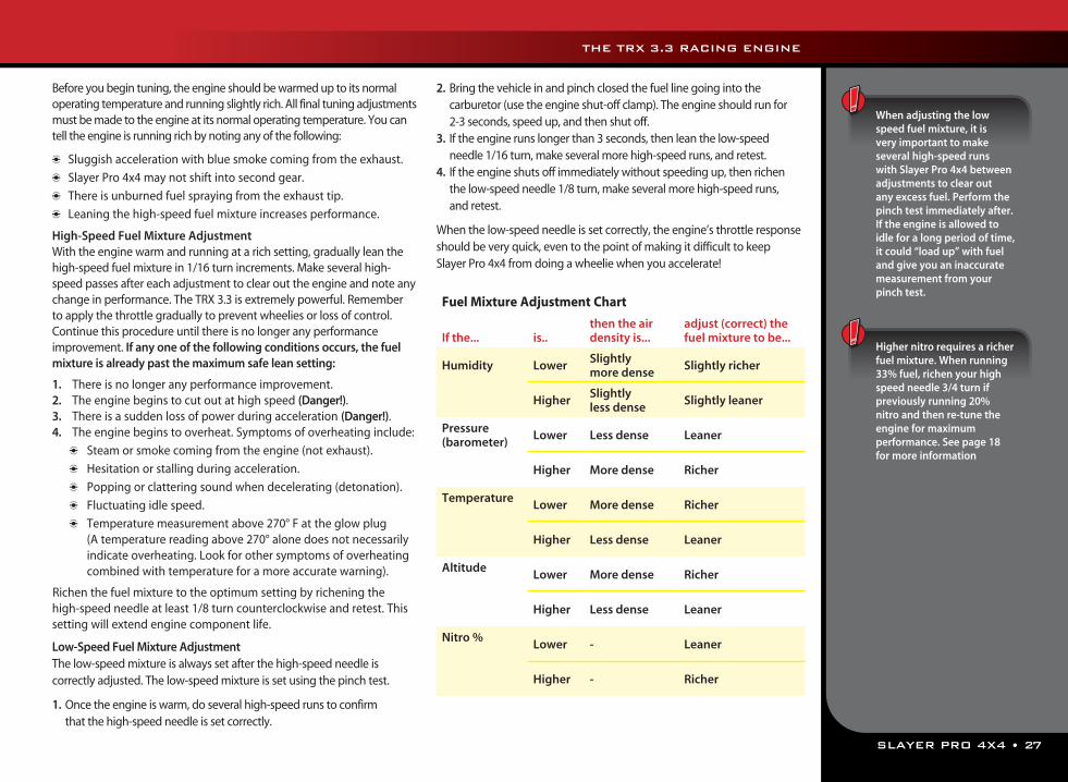
SLAYER PRO 4X4 • 27
Before you begin tuning, the engine should be warmed up to its normal operating temperature and running slightly rich. All final tuning adjustments must be made to the engine at its normal operating temperature. You can tell the engine is running rich by noting any of the following:
Sluggish acceleration with blue smoke coming from the exhaust.
Slayer Pro 4x4 may not shift into second gear.
There is unburned fuel spraying from the exhaust tip.
Leaning the high-speed fuel mixture increases performance.
High-Speed Fuel Mixture AdjustmentWith the engine warm and running at a rich setting, gradually lean the high-speed fuel mixture in 1/16 turn increments. Make several high-speed passes after each adjustment to clear out the engine and note any change in performance. The TRX 3.3 is extremely powerful. Remember to apply the throttle gradually to prevent wheelies or loss of control. Continue this procedure until there is no longer any performance improvement. If any one of the following conditions occurs, the fuel mixture is already past the maximum safe lean setting:
1. There is no longer any performance improvement.2. The engine begins to cut out at high speed (Danger!).3. There is a sudden loss of power during acceleration (Danger!).4. The engine begins to overheat. Symptoms of overheating include:
Steam or smoke coming from the engine (not exhaust).
Hesitation or stalling during acceleration.
Popping or clattering sound when decelerating (detonation).
Fluctuating idle speed.
Temperature measurement above 270° F at the glow plug (A temperature reading above 270° alone does not necessarily
indicate overheating. Look for other symptoms of overheating combined with temperature for a more accurate warning).
Richen the fuel mixture to the optimum setting by richening the high-speed needle at least 1/8 turn counterclockwise and retest. This setting will extend engine component life.
Low-Speed Fuel Mixture AdjustmentThe low-speed mixture is always set after the high-speed needle is correctly adjusted. The low-speed mixture is set using the pinch test.
1. Once the engine is warm, do several high-speed runs to confirm that the high-speed needle is set correctly.
2. Bring the vehicle in and pinch closed the fuel line going into the carburetor (use the engine shut-off clamp). The engine should run for 2-3 seconds, speed up, and then shut off.
3. If the engine runs longer than 3 seconds, then lean the low-speed needle 1/16 turn, make several more high-speed runs, and retest.
4. If the engine shuts off immediately without speeding up, then richen the low-speed needle 1/8 turn, make several more high-speed runs, and retest.
When the low-speed needle is set correctly, the engine’s throttle response should be very quick, even to the point of making it difficult to keep Slayer Pro 4x4 from doing a wheelie when you accelerate!
When adjusting the low speed fuel mixture, it is very important to make several high-speed runs with Slayer Pro 4x4 between adjustments to clear out any excess fuel. Perform the pinch test immediately after. If the engine is allowed to idle for a long period of time, it could “load up” with fuel and give you an inaccurate measurement from your pinch test.
Higher nitro requires a richer fuel mixture. When running 33% fuel, richen your high speed needle 3/4 turn if previously running 20% nitro and then re-tune the engine for maximumperformance. See page 18 for more information
Fuel Mixture Adjustment Chart
If the... is..then the air density is...
adjust (correct) the fuel mixture to be...
Humidity LowerSlightly more dense
Slightly richer
HigherSlightly less dense
Slightly leaner
Pressure (barometer)
Lower Less dense Leaner
Higher More dense Richer
TemperatureLower More dense Richer
Higher Less dense Leaner
AltitudeLower More dense Richer
Higher Less dense Leaner
Nitro %Lower - Leaner
Higher - Richer
THE TRX 3.3 RACING ENGINE
28 • SLAYER PRO 4X4
Idle Speed AdjustmentOnce the high and low-speed mixtures have been set, reduce the idle speed to the minimum reliable idle speed. Remember, this adjustment should be made while the engine is running at normal operating temperature.
1. Turn the throttle trim on the transmitter so the brakes are applied (note its original position). This ensures that the throttle slide is resting against the idle adjustment screw.
2. Turn the screw counterclockwise to reduce the idle speed, or clockwise to increase it. The idle speed should be set as low as possible while still maintaining reliable running characteristics.
3. Reset the throttle trim on the transmitter to its original position.
Fine-Tuning the CarburetorAfter fine-tuning your TRX 3.3 Racing Engine at the end of the break-in procedure, no major adjustments to the fuel mixture are usually necessary. Make note of the temperature, humidity, and barometric pressure at the time you finished fine tuning your carburetor. Current weather conditions can be found online from national websites, local TV news websites, and television. This information will be considered your baseline setting.
You may need to adjust your carburetor needles to compensate for changes in temperature and barometric pressure (air density) from day to day. Generally, you’ll need to richen the fuel mixture when the weather is colder than your baseline temperature and the air density is higher. Lean the fuel mixture when weather is warmer than your baseline temperature and the air density is lower. The chart below provides general guidelines on how weather conditions affect air density when they move higher or lower than your baseline setting (see page 20 for detailed info on how air density affects mixture settings).
Tuning the Engine by TemperatureThe following procedures require an optional infrared temperature probe or on-board temperature gauge (Traxxas on-board digital temperature gauge, part #4091). Engine temperature can be used as an effective tuning aid when you understand the relationship between engine temperature and ambient temperature. The engine operating temperature, when tuned for maximum performance, will vary according to atmospheric conditions, engine load, gauge accuracy, and many other factors. The atmospheric condition that has the most influence on engine
temperature is air temperature. Expect the engine temperature to vary almost in direct proportion to air temperature. Assuming you tuned the engine for the same maximum performance each day, the engine will run about twenty degrees hotter when it’s ninety degrees outside than it would in seventy-degree weather. For this reason, we cannot give you a definitive temperature range that indicates the best possible engine tuning.
There is NO optimal temperature that can be used as a target to deliver the best engine tuning. Do not rely on a temp gauge alone to tune your engine. Tune the engine by paying very close attention to how it responds to changes in fuel mixture (more smoke/less smoke, fast/sluggish, reliable/stalling, smooth sound/ muffled sound, etc). Once the engine is tuned, then observe the temperature.
The temperature gauge can aid you in tuning by giving you a relative indication of how your adjustments are affecting the engine and to help prevent you from reaching excessive engine temperatures. For example, as you lean the fuel mixture, the engine performance will increase along with the temperature. If you continue to lean the fuel mixture and the temperature increases but the engine performance does not change, then you have exceeded the maximum safe lean setting. Make note of the engine temperature. Generally, try to keep your engine from exceeding 270°F when measured at the glow plug. If necessary, increase airflow to the engine by cutting out the rear of the body, windshield, and front valance. In some situations, the engine may perform very well with no stalling, lagging, or hesitation at temperatures above 270°F, particularly in very hot climates. If richening the fuel mixture to bring the temperature down to 270°F results in poor, sluggish performance (engine never cleans out) then return the engine back to a satisfactory state of tune based on how it sounds and performs (always with a visible stream of blue smoke coming from the exhaust) . If engine temperature is exceeding 270°F with proper cooling and no signs of abnormal running, then avoid running the engine at its maximum lean setting. Watch closely for any signs of overheating. Richen the fuel mixture slightly to provide a safety margin of additional cooling lubrication. Symptoms of overheating include:
Steam or smoke coming from the engine (not exhaust). Hesitation or stalling during acceleration. Popping or clattering sound when decelerating (detonation). Fluctuating idle speed.
THE TRX 3.3 RACING ENGINE
SLAYER PRO 4X4 • 29
INTRODUCTIONYour TRX 3.3 Racing Engine is broken in, the fuel mixture is balanced, and the idle is set…now it’s time to have some fun! Before you go on, here are some important precautions to keep in mind.
Don’t run your Slayer Pro 4x4 in water, mud, snow, or wet grass. It’s tempting, but water and mud are easily drawn through the air filter and will severely damage the engine. Small amounts of moisture can cause electronics to fail and loss of control over your Slayer Pro 4x4.
The TRX 3.3 Racing Engine is extremely powerful. Remember to apply the throttle gradually to prevent wheelies or loss of control.
Don’t hold Slayer Pro 4x4 off the ground and rev the engine excessively with no load on the engine. This practice could result in internal engine damage. Avoid over revving the engine when Slayer Pro 4x4 is airborne after a jump.
Avoid excessive high-speed running for extended periods of time or over long distances. This could cause the engine to build up enough speed to exceed maximum safe RPM limits.
Don’t drive your Slayer Pro 4x4 with drive train damage of any kind. The engine could be damaged due to overloads caused by drivetrain friction, or over-revving caused by loose or missing parts.
Don’t tow anything with your Slayer Pro 4x4. The engine is cooled by airflow created by speed. Towing creates a high load on the engine, and at the same time limits cooling of the engine due to low vehicle speed.
If your Slayer Pro 4x4 gets stuck, stop driving immediately. Move the vehicle and then continue driving.
Never turn off the radio system while the engine is running. The truck could run out of control.
Driving Tips Slayer Pro 4x4 is very fast. Select a large area to drive with few
opportunities for collision until you become familiar with Slayer Pro 4x4’s speed and handling.
Do not apply brakes and turn the wheel at the same time. You could tip the truck over.
When jumping, apply some throttle while Slayer Pro 4x4 is in the air to keep the truck’s nose up and land level on all 4 wheels. Be careful not to over-rev the engine or land at full throttle. Either could seriously damage your Slayer Pro 4x4. If the nose of the truck is too high, then quickly tap the brake to level the truck in the air.
Drive over large obstacles (such as curbs and rocks) at an angle, instead of head on. This will allow the suspension to articulate and absorb the impact much easier.
Change or clean the pre-filter element in your air filter after each hour of running. Change or clean the primary filter element every 3 - 4 hours of running. This is critical for the life of your engine. Running time includes the engine break-in period.
DRIVING YOUR SLAYER PRO 4X4
15
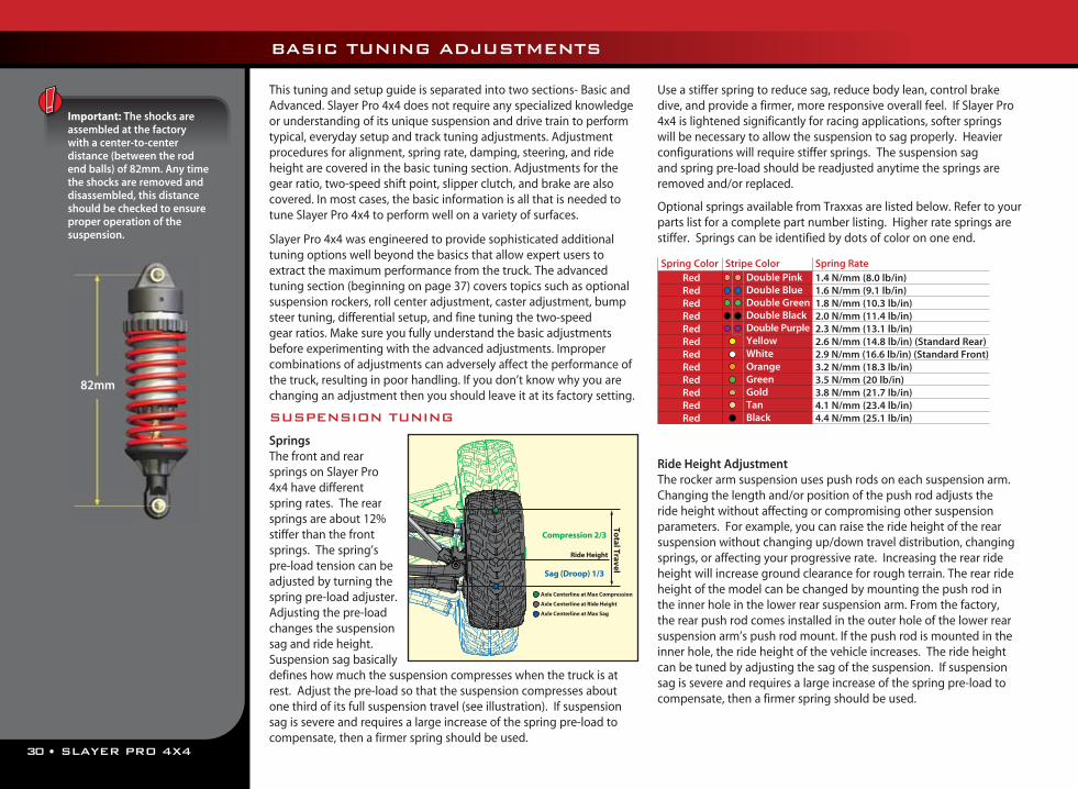
30 • SLAYER PRO 4X4
BASIC TUNING ADJUSTMENTS
This tuning and setup guide is separated into two sections- Basic and Advanced. Slayer Pro 4x4 does not require any specialized knowledge or understanding of its unique suspension and drive train to perform typical, everyday setup and track tuning adjustments. Adjustment procedures for alignment, spring rate, damping, steering, and ride height are covered in the basic tuning section. Adjustments for the gear ratio, two-speed shift point, slipper clutch, and brake are also covered. In most cases, the basic information is all that is needed to tune Slayer Pro 4x4 to perform well on a variety of surfaces.
Slayer Pro 4x4 was engineered to provide sophisticated additional tuning options well beyond the basics that allow expert users to extract the maximum performance from the truck. The advanced tuning section (beginning on page 37) covers topics such as optional suspension rockers, roll center adjustment, caster adjustment, bump steer tuning, differential setup, and fine tuning the two-speed gear ratios. Make sure you fully understand the basic adjustments before experimenting with the advanced adjustments. Improper combinations of adjustments can adversely affect the performance of the truck, resulting in poor handling. If you don’t know why you are changing an adjustment then you should leave it at its factory setting.
SUSPENSION TUNING
SpringsThe front and rear springs on Slayer Pro 4x4 have different spring rates. The rear springs are about 12% stiffer than the front springs. The spring’s pre-load tension can be adjusted by turning the spring pre-load adjuster. Adjusting the pre-load changes the suspension sag and ride height. Suspension sag basically defines how much the suspension compresses when the truck is at rest. Adjust the pre-load so that the suspension compresses about one third of its full suspension travel (see illustration). If suspension sag is severe and requires a large increase of the spring pre-load to compensate, then a firmer spring should be used.
Use a stiffer spring to reduce sag, reduce body lean, control brake dive, and provide a firmer, more responsive overall feel. If Slayer Pro 4x4 is lightened significantly for racing applications, softer springs will be necessary to allow the suspension to sag properly. Heavier configurations will require stiffer springs. The suspension sag and spring pre-load should be readjusted anytime the springs are removed and/or replaced.
Optional springs available from Traxxas are listed below. Refer to your parts list for a complete part number listing. Higher rate springs are stiffer. Springs can be identified by dots of color on one end.
Ride Height AdjustmentThe rocker arm suspension uses push rods on each suspension arm. Changing the length and/or position of the push rod adjusts the ride height without affecting or compromising other suspension parameters. For example, you can raise the ride height of the rear suspension without changing up/down travel distribution, changing springs, or affecting your progressive rate. Increasing the rear ride height will increase ground clearance for rough terrain. The rear ride height of the model can be changed by mounting the push rod in the inner hole in the lower rear suspension arm. From the factory, the rear push rod comes installed in the outer hole of the lower rear suspension arm’s push rod mount. If the push rod is mounted in the inner hole, the ride height of the vehicle increases. The ride height can be tuned by adjusting the sag of the suspension. If suspension sag is severe and requires a large increase of the spring pre-load to compensate, then a firmer spring should be used.
Compression 2/3
Sag (Droop) 1/3
Ride Height
Total Travel
Axle Centerline at Ride Height
Axle Centerline at Max Compression
Axle Centerline at Max Sag
Important: The shocks are assembled at the factory with a center-to-center distance (between the rod end balls) of 82mm. Any time the shocks are removed and disassembled, this distance should be checked to ensure proper operation of the suspension.
82mm
Spring Color Stripe Color Spring RateRed Double Pink 1.4 N/mm (8.0 lb/in) Red Double Blue 1.6 N/mm (9.1 lb/in) Red Double Green 1.8 N/mm (10.3 lb/in)Red Double Black 2.0 N/mm (11.4 lb/in)Red Double Purple 2.3 N/mm (13.1 lb/in)Red Yellow 2.6 N/mm (14.8 lb/in) (Standard Rear)Red White 2.9 N/mm (16.6 lb/in) (Standard Front)Red Orange 3.2 N/mm (18.3 lb/in)Red Green 3.5 N/mm (20 lb/in)Red Gold 3.8 N/mm (21.7 lb/in)Red Tan 4.1 N/mm (23.4 lb/in)Red Black 4.4 N/mm (25.1 lb/in)
SLAYER PRO 4X4 • 31
Adjusting the Pivot Ball CapsThe pivot ball caps should be adjusted so that the pivot balls operate freely in the axle carriers with no excess play. Use the provided four-way suspension multi-tool to tighten or loosen the pivot ball cap.
Shock OilThe 4 oil-filled aluminum shocks (dampers) effectively control the suspension movement by preventing the wheels and tires from continuing to “bounce” after rebounding from a bump. Changing the oil in the shocks can vary the suspension damping effect. Changing the oil to a higher viscosity oil will increase damping. Lowering the viscosity of the oil will cause the suspension damping to be reduced. Damping should be increased (with higher viscosity oil) if the model is bottoming easily over jumps. Damping should be decreased (with thinner viscosity oil) if the model is hopping over small bumps and feels unstable. The viscosity of shock oil is affected by extremes in operating temperature; an oil of certain viscosity will become less viscous at higher temperatures and more viscous at lower temperatures. Operating in regions with cold temperatures may require lower viscosity oil. From the factory, the shocks are filled with SAE-30W silicone oil. Only use 100% silicone oil in the shock.
For shock piston tuning see Advanced Tuning Adjustments on page 37.
Replacing Shock OilThe shocks have to be removed from the vehicle and disassembled to change the oil.
1. Remove the lower spring retainer and shock spring.
2. Remove the upper shock cap using the shock wrench and the suspension multi tool
3. Empty the used shock oil from the shock body.
4. Fill the shock with new silicone shock oil up to the top of the shock body.
5. Slowly move the piston up and down (always keeping it submerged in oil) to release the air bubbles. Let the shock sit for a few minutes to allow any remaining air bubbles to surface.
6. Slowly thread the upper cap with the installed shock bladder onto
the shock body with the suspension multi tool. The excess oil will bleed out of the small hole in the shock cap.
7. Tighten the shock cap until snug. Use the included steel shock wrench to hold onto shock body while tightening.
ALIGNMENT SETTINGSThe alignment settings are critical for optimizing the performance of Slayer Pro 4x4. Adjust your alignment as carefully and precisely as you possibly can.
Toe AdjustmentThe wheels can be adjusted to point straight ahead or have a toe-in or toe-out setting. To help you remember, look down at your feet. For toe-in, your feet point towards each other. For toe-out, your feet point away from each other.
The toe angle of the front wheels can be adjusted by varying the length of the toe links that connect the steering linkage to the front axle carriers. The toe angle of the rear wheels can be adjusted by varying the length of the metal toe links that connect the rear bulkheads to the rear axle carriers. The front toe links and rear toe links are equipped with turnbuckles. The lengths of the toe links can be adjusted by turning them with the included turnbuckle wrench.
Toe Base Factory SettingsFront: 0-degreesRear: 1-degree toe-in each side
Under certain conditions, toe-in can be increased to a maximum of 3 degrees.
BASIC TUNING ADJUSTMENTS
0° 0°
0° 0°
Left Hand
Threads
Right H
and
(Norm
al) Thre
ads
DecreaseLength
IncreaseLength
32 • SLAYER PRO 4X4
BASIC TUNING ADJUSTMENTS
Static Camber AdjustmentThe wheels can be set to have either positive or negative camber (see illustration below). The camber angle changes as the wheel moves up and down through its range of travel. Static camber is the camber angle at the wheel when the vehicle is set at its normal, stationary ride height.
The suspension pivot balls located in the axle carriers adjust the static camber. The pivot balls are protected by blue dust plugs. To adjust your static camber, insert the supplied 2.5 mm hex wrench through the slit in the dust plug and engage the end of the pivot ball (compressing the suspension until the arms are parallel to the ground will allow for easier hex wrench engagement). The upper pivot ball is normally screwed all the way in. Negative camber is achieved by screwing the pivot ball of the lower control arm out. Note: When camber is changed, the toe angle of the wheel has to be reset.
Static Camber Base Factory SettingsFront: 2-degree negative camber each sideRear: 3-degree negative camber each side
TRANSMISSION TUNING
Adjusting the Slipper ClutchYour Slayer Pro 4x4 is equipped with an adjustable Torque-Control™ slipper clutch. The slipper clutch is integrated into the main spur gear on the transmission. The slipper clutch is adjusted by loosening the spring-loaded locknut on the slipper shaft. Use the supplied 8mm open-end metric wrench. To tighten or loosen the slipper nut, insert the 2.0mm hex wrench into the hole in the end of the slipper shaft. This locks the shaft for adjustments. Turn the adjustment nut clockwise to tighten (less slippage) and counter-clockwise to loosen (more slippage). The slipper clutch has two functions:
1. Limiting the engine’s torque output to the wheels to prevent wheelspin on low traction surfaces and help to prevent damage to the gears in the transmission during on-throttle landings.
2. Protecting the drivetrain from sudden impact or shock loads (such as landing from a jump with the engine at full throttle).
From the factory the slipper clutch is set for minimal slippage, just enough to protect the drivetrain from shock loads. On slippery, low traction surfaces such as a hard-packed, dry racetrack you may benefit from loosening the slipper adjustment nut to allow for more clutch slippage. This will make the truck easier and more forgiving to drive by helping to reduce the amount of wheel spin. Loosening the slipper adjustment can also improve performance on extreme high traction surfaces by preventing the front end from lifting off of the ground when accelerating. Make slipper adjustments in small 1/8 turn increments.
The maximum tight setting for the slipper is just at the point where there is little or no tire slippage on a high traction surface such as carpet or a prepared racetrack. The slipper should not be tightened to the point that clutch slippage is completely eliminated. Do not overtighten the slipper nut or you could damage the slipper bearings, pressure plates, or other components.
For caster, roll center, and optional rocker arm tuning see Advanced Tuning Adjustments on page 37.
0° 0°
0° 0°
Positive camber
Negative camber
All of the toe links are installed on the truck so that the left hand thread indicators point to the same direction. This makes it easier to remember which way to turn the wrench to increase or decrease toe link length (the direction is same at all four corners). Note that the groove in the hex indicates the side of the toe link with the left-hand threads.
A camber gauge (available at your local hobby shop) can be a useful tool for alignment setting.
SLAYER PRO 4X4 • 33
Adjusting the Two-Speed TransmissionSlayer Pro 4x4 comes equipped with an adjustable two-speed transmission. When the shift point on the transmission is adjusted correctly, it will maximize acceleration and improve drivability. Use a 2mm hex wrench to adjust the shift point. To make the adjustment, the engine must be off (not running).
1. Shift the transmission into forward gear (shift button down).
2. Remove the rubber access plug from the top of the transmission housing.
3. While looking through the opening, rotate the spur gear to align the cutout (notch) on the internal two-speed clutch drum with the opening.
4. Hold the spur gear and slowly roll the truck forward until the hex on the black adjustment set screw becomes visible in the opening. Note: the truck will only roll forward (not backwards) when the spur gear is held stationary.
5. Insert the 2.0mm hex wrench through the clutch drum and into the adjustment screw.
6. Turn the adjustment screw 1/8 turn counter clockwise to lower the shift point (shifts sooner). Be careful not to loosen the adjustment screw too much or you may cause the screw and spring to fall out (requiring major disassembly and repair). Turn the adjustment screw clockwise for later shifts.
7. Reinstall the rubber access plug to prevent dirt from entering the transmission. Do not put oil or other lubricants into the transmission through the two-speed adjustment access.
8. Check performance by running a test lap after each adjustment. On a small race track with many tight turns, try setting the shift point later so that the truck only shifts into second gear on the main straightaway. This will prevent an unexpected shift in the middle of a turn. On larger tracks it may be necessary to allow earlier shifts for increased speed.
Adjusting the Spur Gear/Clutch Bell Gear Mesh The ideal spur gear/clutch bell gear mesh for Slayer Pro 4x4 is 0.1mm. To set the gear mesh, place a strip of standard letter/A4 size copy or printer paper (about 0.1mm thick) between the mating teeth. Loosen the two horizontal engine mount screws and slide the engine mount up to push the clutch bell gear against the spur gear so that the that the paper is not too tight to pull out or too loose that it will fall out. Tighten the two horizontal engine mount screws securely. When the paper is removed, you should feel only the slightest amount of play between the gears (almost none) and there should be no binding or friction.
Changing the Spur Gear1. Remove the four cap head screws that
secure the engine to the engine mount.
2. Remove the button head screw that secures the pipe hanger to the rear body mount.
3. Carefully remove the engine and exhaust system from the spur gear area to allow enough room to remove the spur gear.
4. Remove the three screws on the slipper clutch assembly using a 2.5mm hex wrench. Slide the spur gear off of the slipper shaft. If the spur gear is too tight on the shaft, gently pry on the back of the gear with a flat screw driver to loosen it.
Repeat the above steps in reverse order to install the new spur gear.
BASIC TUNING ADJUSTMENTS
Shift Sooner
34 • SLAYER PRO 4X4
BASIC TUNING ADJUSTMENTS
STEERING SYSTEMSlayer Pro 4x4 uses a digital servo and a single heavy-duty servo saver for powerful, responsive steering.
Adjusting The Steering System1. Remove the servo horn and steering link from the servo. Disconnect
the steering link from the servo saver.2. Adjust the steering link to be 31.7mm - use “Steering Servo Horn Link
Length Template” below to set length).3. Switch on the power to the receiver and the transmitter.4. Adjust the steering trim on the transmitter to the neutral “0” position.5. Connect one end of the steering link to the servo saver arm and the
other end to the servo horn6. Position the steering servo saver arm perpendicular to the centerline of
the vehicle.7. While holding the steering servo saver arm in
the position mentioned in step 6, install the servo horn onto the servo so the steering link is parallel with the centerline of the vehicle. This will automatically set the servo horn at the 7-degree offset shown in the illustration.
If you are using an aftermarket servo, it is important to use a servo horn designed for Slayer Pro 4x4. Optional steering servo horns are sold separately for use with non-Traxxas servos.
Servo Saver TuningAn optional stiffer spring is available for the servo saver when using servos with metal gear sets (see parts list for details). Do not use this spring with standard Traxxas high-torque servos.
BRAKE SETUP & ADJUSTMENTSlayer Pro 4x4 is equipped with a disc brake that rides on the yoke of the transmission’s front output shaft. The brake is preset at the factory and should not require attention. As the brake material wears, future adjustments may be necessary.
Brake Shoulder Screw AdjustmentThe two shoulder bolts that are used to secure the brake pads to the transmission housing may need to be adjusted periodically as the brake material wears down. They should be tightened so a 0.50mm (.020”) gap exists between the disk and the brake pad (on the transmission side). Adjust in one of the following ways:
1. Use a .50mm feeler gauge between the brake pad insert and brake disk.
2. Push the outer brake pad firmly against the inner pad with your finger, sandwiching the brake disk between the brake calipers. Tighten the brake shoulder bolts until they just barely touch the brake pads. Do not over tighten these fasteners or you could damage the brake calipers. Loosen each of the shoulder bolts by 1 turn.
Brake Linkage AdjustmentWhen correctly adjusted, the brake linkage spring should barely touch the rod guide when the servo is in neutral position (closed throttle). This will ensure no brake drag during operation of the vehicle. The brake adjustment knob can be threaded away from the spring for less braking power if desired. Do not adjust knob to apply pressure against the spring while the servo is in the neutral position. This will induce brake drag and cause undesirable handling.
The position of the z-bend from the factory is in the middle position of the servo horn. Changing this position will affect the way the brake force is applied. The brake adjustment knob will need to be readjusted if this position is changed.
Brake Pad Wear and ReplacementDuring normal use the brake pads should wear at a relatively slow rate. However, if the brake pads wear down close to the metal pad holders, they should be replaced. Any more wear than this could cause damage to the brake parts and improper operation of the brake system.
0.5mmgap
Front of Truck
Less Brake
BrakeLinkageSpring
For adjusting two-speed and gear ratios see Advanced Tuning Adjustments on page 38.
Steering Link Length Template
41.8 mm
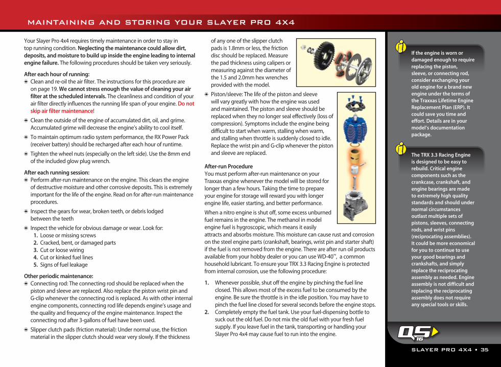
SLAYER PRO 4X4 • 35
If the engine is worn or damaged enough to require replacing the piston, sleeve, or connecting rod, consider exchanging your old engine for a brand new engine under the terms of the Traxxas Lifetime Engine Replacement Plan (ERP). It could save you time and effort. Details are in your model’s documentation package.
The TRX 3.3 Racing Engine is designed to be easy to rebuild. Critical engine components such as the crankcase, crankshaft, and engine bearings are made to extremely high quality standards and should under normal circumstances outlast multiple sets of pistons, sleeves, connecting rods, and wrist pins (reciprocating assemblies). It could be more economical for you to continue to use your good bearings and crankshafts, and simply replace the reciprocating assembly as needed. Engine assembly is not difficult and replacing the reciprocating assembly does not require any special tools or skills.
Your Slayer Pro 4x4 requires timely maintenance in order to stay in top running condition. Neglecting the maintenance could allow dirt, deposits, and moisture to build up inside the engine leading to internal engine failure. The following procedures should be taken very seriously.
After each hour of running: Clean and re-oil the air filter. The instructions for this procedure are
on page 19. We cannot stress enough the value of cleaning your air filter at the scheduled intervals. The cleanliness and condition of your air filter directly influences the running life span of your engine. Do not skip air filter maintenance!
Clean the outside of the engine of accumulated dirt, oil, and grime. Accumulated grime will decrease the engine’s ability to cool itself.
To maintain optimum radio system performance, the RX Power Pack (receiver battery) should be recharged after each hour of runtime.
Tighten the wheel nuts (especially on the left side). Use the 8mm end of the included glow plug wrench.
After each running session: Perform after-run maintenance on the engine. This clears the engine
of destructive moisture and other corrosive deposits. This is extremely important for the life of the engine. Read on for after-run maintenance procedures.
Inspect the gears for wear, broken teeth, or debris lodged between the teeth
Inspect the vehicle for obvious damage or wear. Look for: 1. Loose or missing screws 2. Cracked, bent, or damaged parts 3. Cut or loose wiring 4. Cut or kinked fuel lines 5. Signs of fuel leakage
Other periodic maintenance: Connecting rod: The connecting rod should be replaced when the
piston and sleeve are replaced. Also replace the piston wrist pin and G-clip whenever the connecting rod is replaced. As with other internal engine components, connecting rod life depends engine’s usage and the quality and frequency of the engine maintenance. Inspect the connecting rod after 3-gallons of fuel have been used.
Slipper clutch pads (friction material): Under normal use, the friction material in the slipper clutch should wear very slowly. If the thickness
of any one of the slipper clutch pads is 1.8mm or less, the friction disc should be replaced. Measure the pad thickness using calipers or measuring against the diameter of the 1.5 and 2.0mm hex wrenches provided with the model.
Piston/sleeve: The life of the piston and sleeve will vary greatly with how the engine was used and maintained. The piston and sleeve should be replaced when they no longer seal effectively (loss of compression). Symptoms include the engine being difficult to start when warm, stalling when warm, and stalling when throttle is suddenly closed to idle. Replace the wrist pin and G-clip whenever the piston and sleeve are replaced.
After-run ProcedureYou must perform after-run maintenance on your Traxxas engine whenever the model will be stored for longer than a few hours. Taking the time to prepare your engine for storage will reward you with longer engine life, easier starting, and better performance.
When a nitro engine is shut off, some excess unburned fuel remains in the engine. The methanol in model engine fuel is hygroscopic, which means it easily attracts and absorbs moisture. This moisture can cause rust and corrosion on the steel engine parts (crankshaft, bearings, wrist pin and starter shaft) if the fuel is not removed from the engine. There are after run oil products available from your hobby dealer or you can use WD-40™, a common household lubricant. To ensure your TRX 3.3 Racing Engine is protected from internal corrosion, use the following procedure:
1. Whenever possible, shut off the engine by pinching the fuel line closed. This allows most of the excess fuel to be consumed by the engine. Be sure the throttle is in the idle position. You may have to pinch the fuel line closed for several seconds before the engine stops.
2. Completely empty the fuel tank. Use your fuel-dispensing bottle to suck out the old fuel. Do not mix the old fuel with your fresh fuel supply. If you leave fuel in the tank, transporting or handling your Slayer Pro 4x4 may cause fuel to run into the engine.
MAINTAINING AND STORING YOUR SLAYER PRO 4X4
16
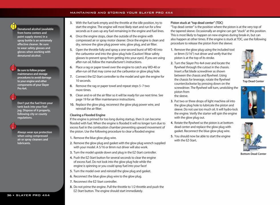
36 • SLAYER PRO 4X4
3. With the fuel tank empty and the throttle at the idle position, try to start the engine. The engine will most likely start and run for a few seconds as it uses up any fuel remaining in the engine and fuel lines.
4. Once the engine stops, clean the outside of the engine with compressed air or spray motor cleaner. Once the engine is clean and dry, remove the glow plug power wire, glow plug, and air filter.
5. Open the throttle fully and spray a one-second burst of WD-40 into the carburetor and into the glow plug hole (Caution! Wear safety glasses to prevent spray from getting into your eyes). If you are using after-run oil, follow the manufacturer’s instructions.
6. Place a rag or paper towel over the engine to catch any WD-40 or after-run oil that may come out the carburetor or glow plug hole.
7. Connect the EZ-Start controller to the model and spin the engine for 10 seconds.
8. Remove the rag or paper towel and repeat steps 5–7 two more times.
9. Clean and re-oil the air filter so it will be ready for use next time. See page 19 for air filter maintenance instructions.
10. Replace the glow plug, reconnect the glow plug power wire, and reinstall the air filter.
Clearing a Flooded EngineIf the engine is primed for too long during startup, then it can become flooded with fuel. When the engine is flooded it will no longer turn due to excess fuel in the combustion chamber preventing upward movement of the piston. Use the following procedure to clear a flooded engine:
1. Remove the blue glow plug wire.
2. Remove the glow plug and gasket with the glow plug wrench supplied with your model. A 5/16 or 8mm nut driver will also work.
3. Turn the model upside down and plug in the EZ-Start controller.
4. Push the EZ-Start button for several seconds to clear the engine of excess fuel. Do not look into the glow plug hole while the engine is spinning or you could spray fuel into your face!
5. Turn the model over and reinstall the glow plug and gasket.
6. Reconnect the blue glow plug wire to the glow plug.
7. Reconnect the EZ-Start controller.
8. Do not prime the engine. Pull the throttle to 1/2 throttle and push the EZ-Start button. The engine should start immediately.
Piston stuck at “top dead center” (TDC)“Top dead center” is the position where the piston is at the very top of the tapered sleeve. Occasionally an engine can get “stuck” at this position. This is most likely to happen on new engines during break-in, but can also happen at other times. If the engine is stuck at TDC, use the following procedure to release the piston from the sleeve:
1. Remove the glow plug using the included tool or 8mm (5/16”) nut driver and verify that the piston is at the top of its stroke.
2. Turn the Slayer Pro 4x4 over and locate the flywheel through the cutout in the chassis. Insert a flat blade screwdriver as shown between the chassis and flywheel. Using the chassis for leverage, rotate the flywheel counterclockwise by pressing down on the screwdriver. The flywheel will turn, unsticking the piston from the sleeve.
3. Put two or three drops of light machine oil into the glow plug hole to lubricate the piston and sleeve. Do not use too much oil. It will hydro-lock the engine. Verify the starter will spin the engine with the glow plug out.
4. Rotate the flywheel so the piston is at bottom dead center and replace the glow plug with gasket. Reconnect the blue glow plug wire.
5. You should now be able to start the engine with the EZ-Start.
Denatured alcohol (available from home centers and paint supply stores) in a spray bottle is an extremely effective cleaner. Be sure to wear safety glasses and gloves when working with denatured alcohol.
Be sure to follow proper maintenance and storage procedures to avoid damage to your engine and other components of your Slayer Pro 4x4.
Don’t put the fuel from your tank back into your fuel jug. Dispose of it properly, following city or county regulations.
Always wear eye protection when using compressed air or spray cleaners and lubricants.
Top Dead Center
Bottom Dead Center
MAINTAINING AND STORING YOUR SLAYER PRO 4X4
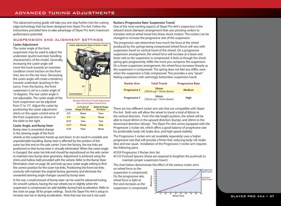
SLAYER PRO 4X4 • 37
This advanced tuning guide will take you one step further into the cutting edge technology that has been designed into Slayer Pro 4x4. Follow the instructions provided here to take advantage of Slayer Pro 4x4’s maximum performance potential.
SUSPENSION AND ALIGNMENT SETTINGSCaster AdjustmentThe caster angle of the front suspension may be used to adjust the understeer (push)/oversteer handling characteristics of the model. Generally, increasing the caster angle will move the truck towards an oversteer condition (more traction on the front tires, less on the rear tires). Decreasing the caster angle will create a tendency towards understeer (pushing in the turns). From the factory, the front suspension is set to a caster angle of 10-degrees. The rear caster angle is not adjustable. The caster angle of the front suspension can be adjusted from 5° to 15°. Adjust the caster by positioning the caster adjustment shims on the upper control arms of the front suspension as shown in the table to the right.
Caster Angle, and Bump SteerBump steer is unwanted change in the steering angle of the front wheels as the suspension travels up and down. It can result in unstable andunpredictable handling. Bump steer is affected by the position of theouter toe link end on the axle carrier. From the factory, the toe links arepositioned so that bump steer is virtually eliminated. When the caster angle is changed, the outer toe link end should be repositioned on the axle carrier to maintain zero bump steer geometry. Adjustment is achieved using the shims and hollow balls provided with the vehicle. Refer to the Bump Steer Elimination chart on page 38, and look up your caster angle setting to find the correct position for the outer toe links. Positioning the front toe-links correctly will maintain the original factory geometry and eliminate the unwanted steering angle changes caused by bump steer.
In the rear, a small amount of bump steer can be used for advanced tuning. On smooth surfaces, having the rear wheels toe-in slightly when the suspension is compressed can add stability during hard acceleration. Refer to the chart on page 38 for proper settings. Stock the Slayer Pro 4x4 is setup to increase rear toe-in during acceleration. Note that rear toe-out is not used.
Rockers (Progressive Rate/ Suspension Travel)One of the most exciting aspects of Slayer Pro 4x4’s suspension is the inboard shock (damper) arrangement that uses pivoting rockers to translate vertical wheel travel into linear shock motion. The rockers can be changed to increase the progressive rate of the suspension.
The progressive rate determines how much the force at the wheel produced by the springs being compressed (wheel force) will vary with suspension travel (or vertical travel of the wheel). On a progressive suspension arrangement, the wheel force will increase at a faster and faster rate as the suspension is compressed. It feels as though the shock spring gets progressively stiffer the more you compress the suspension. On a linear suspension arrangement, the wheel force increases linearly as the suspension is compressed. The spring does not feel any stiffer, even when the suspension is fully compressed. This provides a very “plush” feeling suspension with seemingly bottomless suspension travel.
There are two different rocker arm sets that are compatible with Slayer Pro 4x4. Both sets will allow the wheel to travel a total of 60mm in the vertical direction. From the ride height position, the wheel will be able to travel 40mm in the upward direction (bump), and 20mm in the downward direction (droop). The Slayer Pro 4x4 comes equipped with the Progressive 2 rocker set, which offers a good balance of progressive rate for predictable body roll, brake dive, and high-speed stability.
The Progressive 3 rocker arm set (available separately) uses a higher progressive rate that will provide a firmer feel, reducing body roll, brake dive and rear squat. Installation of the Progressive 3 rocker arm requires the following parts:
#5359 Progressive 3 Rocker Arm Set#5133 Pushrod Spacers (these are required to lengthen the pushrods to
maintain proper suspension travel.)
The chart below demonstrate the effect of the various rocker arms on wheel force as the suspension is compressed. On the progressive rate, wheel force is light at first and increases as the suspension is compressed.
Rocker Arm Total Travel Progressive Rate
Progressive 2 50mm(35mm up / 15mm down) Medium
Progressive 3 50mm(35mm up / 15mm down) High
Caster adjustment shims (2 front, 2 rear)
Vertical
Ground plane
10°
CasterIn Front of
Hinge Pin BossBehind Hinge
Pin Boss
5.0° None Four
7.5° One Three
10.0° Two Two
12.5° Three One
15.0° Four None
Number & Position of Caster Adjustment Shims (Front Upper Control Arm)
ADVANCED TUNING ADJUSTMENTS
Constant Rate Travel
Wheel Travel
Wh
eel F
orc
e
0
2468
101214161820
10 20 30 40 50 60 70 80 90
ProgressiveRate Travel
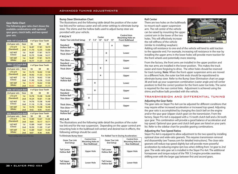
38 • SLAYER PRO 4X4
Bump Steer Elimination ChartThe illustrations and the following table detail the position of the outertoe link end for various caster and roll center settings to eliminate bumpsteer. The shims and the hollow balls used to adjust bump steer areprovided with your vehicle.
REARThe illustrations and the following table detail the position of the outer toe link end for the rear suspension. Depending on the upper control arm mounting hole in the bulkhead (roll center) and desired toe-in effects, the following settings should be used.
Roll CenterThere are two holes on the bulkheads to mount each upper suspension arm. The roll center of the vehicle can be raised by mounting the upper control arm in the lower of the two holes. This will effectively increase the roll stiffness of the vehicle (similar to installing swaybars). Adding roll resistance to one end of the vehicle will tend to add traction to the opposite end. For example, increasing roll resistance in the rear by installing the upper arms in the lower holes will provide more traction for the front wheels and potentially more steering. From the factory, the front arms are installed in the upper position and the rear arms are installed in the lower position. This makes the truck easier and more forgiving to drive. The other holes should be reserved for track tuning. Note: When the front upper suspension arms are moved to a different hole, the outer toe link ends should be repositioned to eliminate bump steer. Refer to the Bump Steer Elimination chart on page 38 and look up your suspension combination (caster angle and roll center position) to find the correct position for the front outer toe links. The same is required for the rear control links. Adjustment is achieved using the shims and hollow balls provided with the vehicle.
TRANSMISSION AND DIFFERENTIAL TUNINGAdjusting the Gear RatioThe gear ratio on Slayer Pro 4x4 can be adjusted for different conditions that may require either increased acceleration or increased top speed. Adjusting the gear ratio is accomplished by changing the clutch bell on the engine and/or the spur gear (slipper clutch gear) on the transmission. From the factory, Slayer Pro 4x4 is equipped with a 15-tooth clutch bell and a 36-tooth spur gear. This combination will provide a good balance of acceleration and top speed. Optional spur gears and clutch bell gears are listed on your parts list. Refer to the sidebar chart for possible gearing combinations.
Adjusting the Two-Speed RatiosSlayer Pro 4x4 is equipped to allow adjustment to the two-speed by installing optional close and wide-ratio gearsets. This requires transmission removal and disassembly (see Traxxas.com for detailed instructions). The close ratio gearsets will reduce top speed slightly but will provide more powerful acceleration by reducing engine rpm loss when shifting from 1st gear to 2nd gear. The wide ratio gear set is installed in the Slayer Pro 4x4. The additional horsepower and torque output of the TRX 3.3 engine provides seamless shifting even with the larger gap between first and second gears.
Outer Toe Link End SetupCaster
5° 7.5° 10° 12.5° 15°
Control Arm Mounting Hole on
Front Bulkhead
Upper
Lower
Upper
Lower
Upper
Lower
Upper
Lower
Upper
Standard Hollow Ball
Thin Shim
Thick Shim
Thin ShimStandardHollow Ball
Thick Shim
Tall Center Hollow Ball
Thick ShimStandardHollow Ball
Thin Shim
Thick Shim
Thin Shim
StandardHollow Ball
FRONT
Upper Control ArmUpper Mounting Holes
Upper Control ArmLower Mounting Holes
ADVANCED TUNING ADJUSTMENTS
*stock configuration out of the box
With 14T Clutch Bell # of Spur Gear Teeth
2nd gear sets Gear 36 38 40
17T/37T 1st 16.87 17.81 18.75(Standard) 2nd 11.70 12.35 13.00
16T/40T 1st 16.87 17.81 18.75(Close) 2nd 12.75 13.46 14.17
18T/38T 1st 16.87 17.81 18.75(Wide) 2nd 10.77 11.37 11.97
With 15T Clutch Bell (standard)
# of Spur Gear Teeth
2nd gear sets Gear 36 38 40
17T/37T 1st 15.75 16.62 17.50(Standard) 2nd 10.92 11.53 12.14
16T/40T 1st 15.75 16.62 17.50(Close) 2nd 11.90 12.56 13.22
18T/38T 1st 15.75* 16.62 17.50(Wide) 2nd 10.05* 10.61 11.17
With 16T Clutch Bell # of Spur Gear Teeth
2nd gear sets Gear 36 38 40
17T/37T 1st 14.76 15.58 16.40(Standard) 2nd 10.24 10.81 11.38
16T/40T 1st 14.76 15.58 16.40(Close) 2nd 11.16 11.78 12.40
18T/38T 1st 14.76 15.58 16.40(Wide) 2nd 9.42 9.95 10.47
With 17T Clutch Bell # of Spur Gear Teeth2nd gear sets Gear 36 38 40
17T/37T 1st 13.89 14.67 15.44(Standard) 2nd 9.64 10.17 10.71
16T/40T 1st 13.89 14.67 15.44(Close) 2nd 10.50 11.09 11.67
18T/38T 1st 13.89 14.67 15.44(Wide) 2nd 8.87 9.36 9.85
Gear Ratio ChartThe following gear ratio chart shows the available combinations with optional spur gears, clutch bells, and two-speed gear sets.
Outer Toe Link End Setup
Control Arm Mounting Hole on
Rear Bulkhead
Upper Hole
Lower Hole
Outer Toe Link End Setup
Control Arm Mounting Hole on
Rear Bulkhead
Upper Hole
Lower Hole
Tall Center Hollow Ball
Tall Lower Hollow Ball
Tall Upper Hollow Ball
Tall Center Hollow Ball
To Eliminate Bump Steer: For Added Toe-In During Acceleration:
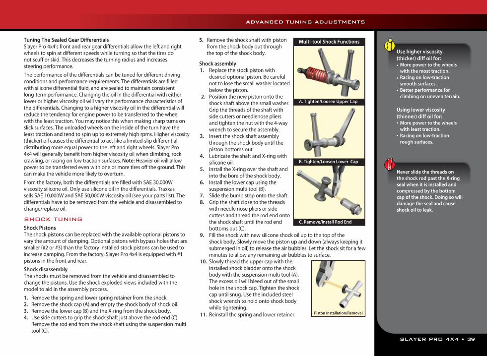
SLAYER PRO 4X4 • 39
ADVANCED TUNING ADJUSTMENTS
Tuning The Sealed Gear DifferentialsSlayer Pro 4x4’s front and rear gear differentials allow the left and right wheels to spin at different speeds while turning so that the tires do not scuff or skid. This decreases the turning radius and increases steering performance.
The performance of the differentials can be tuned for different driving conditions and performance requirements. The differentials are filled with silicone differential fluid, and are sealed to maintain consistent long-term performance. Changing the oil in the differential with either lower or higher viscosity oil will vary the performance characteristics of the differentials. Changing to a higher viscosity oil in the differential will reduce the tendency for engine power to be transferred to the wheel with the least traction. You may notice this when making sharp turns on slick surfaces. The unloaded wheels on the inside of the turn have the least traction and tend to spin up to extremely high rpms. Higher viscosity (thicker) oil causes the differential to act like a limited-slip differential, distributing more equal power to the left and right wheels. Slayer Pro 4x4 will generally benefit from higher viscosity oil when climbing, rock crawling, or racing on low traction surfaces. Note: Heavier oil will allow power to be transferred even with one or more tires off the ground. This can make the vehicle more likely to overturn.
From the factory, both the differentials are filled with SAE 30,000W viscosity silicone oil. Only use silicone oil in the differentials. Traxxas sells SAE 10,000W and SAE 50,000W viscosity oil (see your parts list). The differentials have to be removed from the vehicle and disassembled to change/replace oil.
SHOCK TUNINGShock PistonsThe shock pistons can be replaced with the available optional pistons to vary the amount of damping. Optional pistons with bypass holes that are smaller (#2 or #3) than the factory installed stock pistons can be used to increase damping. From the factory, Slayer Pro 4x4 is equipped with #1 pistons in the front and rear.
Shock disassemblyThe shocks must be removed from the vehicle and disassembled to change the pistons. Use the shock exploded views included with the model to aid in the assembly process.
1. Remove the spring and lower spring retainer from the shock. 2. Remove the shock cap (A) and empty the shock body of shock oil. 3. Remove the lower cap (B) and the X-ring from the shock body. 4. Use side cutters to grip the shock shaft just above the rod end (C).
Remove the rod end from the shock shaft using the suspension multi tool (C).
5. Remove the shock shaft with piston from the shock body out through the top of the shock body.
Shock assembly1. Replace the stock piston with
desired optional piston. Be careful not to lose the small washer located below the piston.
2. Position the new piston onto the shock shaft above the small washer. Grip the threads of the shaft with side cutters or needlenose pliers and tighten the nut with the 4-way wrench to secure the assembly.
3. Insert the shock shaft assembly through the shock body until the piston bottoms out.
4. Lubricate the shaft and X-ring with silicone oil.
5. Install the X-ring over the shaft and into the bore of the shock body.
6. Install the lower cap using the suspension multi tool (B).
7. Slide the bump stop onto the shaft. 8. Grip the shaft close to the threads
with needle nose pliers or side cutters and thread the rod end onto the shock shaft until the rod end bottoms out (C).
9. Fill the shock with new silicone shock oil up to the top of the shock body. Slowly move the piston up and down (always keeping it submerged in oil) to release the air bubbles. Let the shock sit for a few minutes to allow any remaining air bubbles to surface.
10. Slowly thread the upper cap with the installed shock bladder onto the shock body with the suspension multi tool (A). The excess oil will bleed out of the small hole in the shock cap. Tighten the shock cap until snug. Use the included steel shock wrench to hold onto shock body while tightening.
11. Reinstall the spring and lower retainer.
A. Tighten/Loosen Upper Cap
C. Remove/Install Rod End
B. Tighten/Loosen Lower Cap
Multi-tool Shock Functions
Piston Installation/Removal
Never slide the threads on the shock rod past the X-ring seal when it is installed and compressed by the bottom cap of the shock. Doing so will damage the seal and cause shock oil to leak.
Use higher viscosity (thicker) diff oil for:• More power to the wheels
with the most traction.• Racing on low-traction
smooth surfaces .• Better performance for
climbing on uneven terrain.
Using lower viscosity (thinner) diff oil for:• More power to the wheels
with least traction.• Racing on low-traction
rough surfaces.
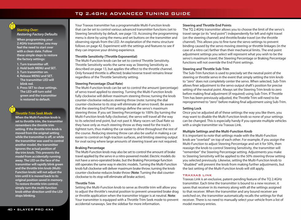
40 • SLAYER PRO 4X4
Your Traxxas transmitter has a programmable Multi-Function knob that can be set to control various advanced transmitter functions (set to Steering Sensitivity by default, see page 13). Accessing the programming menu is done by using the menu and set buttons on the transmitter and observing signals from the LED. An explanation of the menu structure follows on page 42. Experiment with the settings and features to see if they can improve your driving experience.
Throttle Sensitivity (Throttle Exponential)The Multi-Function knob can be set to control Throttle Sensitivity. Throttle Sensitivity works the same way as Steering Sensitivity as described on page 13, but applies the effect to the throttle channel. Only forward throttle is affected; brake/reverse travel remains linear regardless of the Throttle Sensitivity setting.
Steering Percentage (Dual Rate)The Multi-Function knob can be set to control the amount (percentage) of servo travel applied to steering. Turning the Multi-Function knob fully clockwise will deliver maximum steering throw; turning the knob counter-clockwise reduces steering throw (note: turning the dial counter-clockwise to its stop will eliminate all servo travel). Be aware that the steering End Point settings define the servo’s maximum steering throw. If you set Steering Percentage to 100% (by turning the Multi-Function knob fully clockwise), the servo will travel all the way to its selected end point, but not past it. Many racers set Dual Rate so they have only as much steering throw as they need for the track’s tightest turn, thus making the car easier to drive throughout the rest of the course. Reducing steering throw can also be useful in making a car easier to control on high-traction surfaces, and limiting steering output for oval racing where large amounts of steering travel are not required.
Braking PercentageThe Multi-Function knob may also be set to control the amount of brake travel applied by the servo in a nitro-powered model. Electric models do not have a servo-operated brake, but the Braking Percentage function still operates the same way in electric models. Turning the Multi-Function knob full clockwise will deliver maximum brake throw; turning the knob counter-clockwise reduces brake throw (Note: Turning the dial counter-clockwise to its stop will eliminate all brake action).
Throttle TrimSetting the Multi-Function knob to serve as throttle trim will allow you to adjust the throttle’s neutral position to prevent unwanted brake drag or throttle application when the transmitter trigger is at neutral. Note: Your transmitter is equipped with a Throttle Trim Seek mode to prevent accidental runaways. See the sidebar for more information.
Steering and Throttle End PointsThe TQ 2.4GHz transmitter allows you to choose the limit of the servo’s travel range (or its “end point”) independently for left and right travel (on the steering channel) and throttle/brake travel (on the throttle channel). This allows you to fine-tune the servo settings to prevent binding caused by the servo moving steering or throttle linkages (in the case of a nitro car) farther than their mechanical limits. The end point adjustment settings you select will represent what you wish to be the servo’s maximum travel; the Steering Percentage or Braking Percentage functions will not override the End Point settings.
Steering and Throttle Sub-TrimThe Sub-Trim function is used to precisely set the neutral point of the steering or throttle servo in the event that simply setting the trim knob to “zero” does not completely center the servo. When selected, Sub-Trim allows finer adjustment to the servo output shaft’s position for precise setting of the neutral point. Always set the Steering Trim knob to zero before making final adjustment (if required) using Sub-Trim. If Throttle Trim has been previously adjusted, the Throttle Trim will need to be reprogrammed to “zero” before making final adjustment using Sub-Trim.
Setting LockOnce you’ve adjusted all of these settings the way you like them, you may want to disable the Multi-Function knob so none of your settings can be changed. This is especially handy if you operate multiple vehicles with a single transmitter via Traxxas Link.
Multiple Settings and the Multi-Function KnobIt is important to note that settings made with the Multi-Function knob are “overlaid” on top of each other. For example, if you assign the Multi-Function to adjust Steering Percentage and set it for 50%, then reassign the knob to control Steering Sensitivity, the transmitter will “remember” the Steering Percentage setting. Adjustments you make to Steering Sensitivity will be applied to the 50% steering throw setting you selected previously. Likewise, setting the Multi-Function knob to “disabled” will prevent the knob from making further adjustments, but the last setting of the Multi-Function knob will still apply.
TRAXXAS LINKTraxxas Link is an exclusive, patent-pending feature of the TQ 2.4GHz transmitter. Each time the transmitter is bound to a new receiver, it saves that receiver in its memory along with all the settings assigned to that receiver. When the transmitter and any bound receiver are switched on, the transmitter automatically recalls the settings for that receiver. There is no need to manually select your vehicle from a list of model memory entries.
Starting Over: Restoring Factory Defaults
When programming your 2.4GHz transmitter, you may feel the need to start over with a clean slate. Follow these simple steps to restore the factory settings:
1. Turn transmitter off.2. Hold both MENU and SET.3. Turn transmitter on.4. Release MENU and SET.
The transmitter LED will blink red.
5. Press SET to clear settings. The LED will turn solid green and the transmitter is restored to default.
Throttle Trim Seek ModeWhen the Multi-Function knob is set to throttle trim, the transmitter remembers the throttle trim setting. If the throttle trim knob is moved from the original setting while the transmitter is off, or while the transmitter was used to control another model, the transmitter ignores the actual position of the trim knob. This prevents the model from accidentally running away. The LED on the face of the transmitter will rapidly blink green and the throttle trim knob (Multi-Function knob) will not adjust the trim until it is moved back to its original position saved in memory. To restore throttle trim control, simply turn the multi-function knob either direction until the LED stops blinking.
TQ 2.4GHz ADVANCED TUNING GUIDE
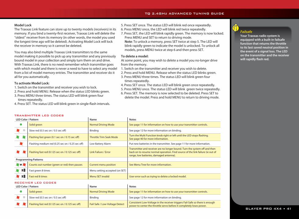
SLAYER PRO 4X4 • 41
TQ 2.4GHz ADVANCED TUNING GUIDE
Model LockThe Traxxas Link feature can store up to twenty models (receivers) in its memory. If you bind a twenty-first receiver, Traxxas Link will delete the “oldest” receiver from its memory (in other words, the model you used the longest time ago will be deleted). Activating Model Lock will lock the receiver in memory so it cannot be deleted.
You may also bind multiple Traxxas Link transmitters to the same model making it possible to pick up any transmitter and any previously bound model in your collection and simply turn them on and drive. With Traxxas Link, there is no need remember which transmitter goes with which model and there is never a need to have to select any model from a list of model memory entries. The transmitter and receiver do it all for you automatically.
To activate Model Lock:1. Switch on the transmitter and receiver you wish to lock. 2. Press and hold MENU. Release when the status LED blinks green.3. Press MENU three times. The status LED will blink green four
times repeatedly.4. Press SET. The status LED will blink green in single-flash intervals.
5. Press SET once. The status LED will blink red once repeatedly. 6. Press MENU once, the LED will blink red twice repeatedly. 7. Press SET, the LED will blink rapidly green. The memory is now locked.
Press MENU and SET to return to driving mode. Note: To unlock a memory, press SET twice at step 5. The LED will
blink rapidly green to indicate the model is unlocked. To unlock all models, press MENU twice at step 6 and then press SET.
To delete a model:At some point, you may wish to delete a model you no-longer drive from the memory.1. Switch on the transmitter and receiver you wish to delete. 2. Press and hold MENU. Release when the status LED blinks green.3. Press MENU three times. The status LED will blink green four
times repeatedly.4. Press SET once. The status LED will blink green once repeatedly. 5. Press MENU once. The status LED will blink green twice repeatedly. 6. Press SET. The memory is now selected to be deleted. Press SET to
delete the model. Press and hold MENU to return to driving mode.
FailsafeYour Traxxas radio system is equipped with a built-in failsafe function that returns the throttle to its last saved neutral position in the event of a signal loss. The LED on the transmitter and the receiver will rapidly flash red.
LED Color / Pattern Name Notes
Solid green Normal Driving Mode See page 11 for information on how to use your transmitter controls.
Slow red (0.5 sec on / 0.5 sec off) Binding See page 12 for more information on binding.
Flashing fast green (0.1 sec on / 0.15 sec off) Throttle Trim Seek ModeTurn the Multi Function knob right or left until the LED stops flashing. See page 40 for more information.
Flashing medium red (0.25 sec on / 0.25 sec off) Low Battery Alarm Put new batteries in the transmitter. See page 11 for more information.
Flashing fast red (0.125 sec on / 0.125 sec off) Link Failure / ErrorTransmitter and receiver are no longer bound. Turn the system off and then back on to resume normal operation. Find source of the link failure (ie out of range, low batteries, damaged antenna).
Programming Patterns
Counts out number (green or red) then pauses Current menu position See Menu Tree for more information.
Fast green 8 times Menu setting accepted (on SET)
Fast red 8 times Menu SET invalid User error such as trying to delete a locked model.
LED Color / Pattern Name Notes
Solid green Normal Driving Mode See page 11 for information on how to use your transmitter controls.
Slow red (0.5 sec on / 0.5 sec off) Binding See page 12 for more information on binding.
Flashing fast red (0.125 sec on / 0.125 sec off) Fail-Safe / Low-Voltage DetectConsistent Low-Voltage in the receiver triggers Fail-Safe so there is enough power to center the throttle servo before it completely loses power.
x 8x 8
or
TRANSMITTER LED CODES
RECEIVER LED CODES
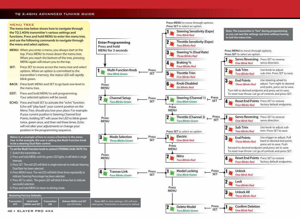
42 • SLAYER PRO 4X4
Press MENU to move through options. Press SET to select an option.
Press MENU to move through options. Press SET to select an option.
Press SET to select an option.
Enter ProgrammingPress and hold MENU for 3 seconds
Steering Sensitivity (Expo)One Blink Red
1
ElectricOne Blink Red
1
UnlockOne Blink Red
1
Servo ReversingOne Blink Red
1
Servo ReversingOne Blink Red
1
Confirm DeletionOne Blink Red
1
Multi-Function KnobOne Blink Green
1
Channel SetupTwo Blinks Green
2
Mode SelectionThree Blinks Green
3
Traxxas-LinkFour Blinks Green
4
Steering (Channel 1)One Blink Green
1
Model LockingOne Blink Green
1
Throttle (Channel 2)Two Blinks Green
2
Delete ModelTwo Blinks Green
2
Throttle Sensitivity (Expo)Two Blinks Red
2
NitroTwo Blinks Red
2
LockTwo Blinks Red
2
Sub TrimTwo Blinks Red
2
Sub TrimTwo Blinks Red
2
Steering % (Dual Rate)Three Blinks Red
3
Unlock AllThree Blinks Red
3
End PointsThree Blinks Red
3
Braking % Four Blinks Red
4
Reset End PointsFour Blinks Red
4
Throttle TrimFive Blinks Red
5
Knob DisabledSix Blinks Red
6
Press MENU
Press MENU
Press MENU
Press MENU
Press MENU
Press MENU
Press SET
Press SET
Press SET
Press SET
Press SET
Press SET
Press SET
Press SET
Press SET to reverse servo direction.
Press SET to reverse servo direction.
Press SET to restore factory default endpoints.
Reset End PointsFour Blinks Red
4 Press SET to restore factory default endpoints.
Use knob to adjust sub-trim. Press SET to save.
Use knob to adjust sub-trim. Press SET to save.
Use steering wheel to adjust. Turn right to desired end point, press set to save.
Turn left to desired endpoint and press set to save. To reset max throw: Let go of controls and press SET.
TQ 2.4GHz ADVANCED TUNING GUIDE
Note: The transmitter is “live” during programming so you can test the settings real time without having to exit the menu tree.
End PointsThree Blinks Red
3 Use trigger to adjust. Pull back to desired end point, press set to save. Push
forward to desired endpoint and press set to save. To reset max throw: Let go of controls and press SET.
The menu tree below shows how to navigate through the TQ 2.4GHz transmitter’s various settings and functions. Press and hold MENU to enter the menu tree, and use the following commands to navigate through the menu and select options.
MENU: When you enter a menu, you always start at the top. Press MENU to move down the menu tree. When you reach the bottom of the tree, pressing MENU again will return you to the top.
SET: Press SET to move across the menu tree and select options. When an option is committed to the transmitter’s memory, the status LED will rapidly blink green.
BACK: Press both MENU and SET to go back one level in the menu tree.
EXIT: Press and hold MENU to exit programming. Your selected options will be saved.
ECHO: Press and hold SET to activate the “echo” function. Echo will “play back” your current position on the Menu Tree, should you lose your place. For example: If your current position is Steering Channel End Points, holding SET will cause the LED to blink green twice, green once, and then red three times. Echo will not alter your adjustments or change your position in the programming sequence.
MENU TREE
Below is an example of how to access a function in the menu tree. In the example, the user is setting the Multi-Function knob to be a steering Dual Rate control.
To set the Multi-Function knob to control STEERING DUAL RATE (%):1. Switch the transmitter on2. Press and hold MENU until the green LED lights. It will blink in single
intervals.3. Press SET. The red LED will blink in single intervals to indicate Steering
Dual Rate has been selected.4. Press MENU twice. The red LED will blink three times repeatedly to
indicate Steering Percentage has been selected.5. Press SET to select. The green LED will blink 8 times fast to indicate
successful selection.6. Press and hold MENU to return to driving mode.
Restoring Factory Defaults:
Transmitter OFF
Hold both MENU and SET
Transmitter ON
Release MENU and SET red LED blinks
Press SET to clear settings. LED will turn solid green. Transmitter is restored to default
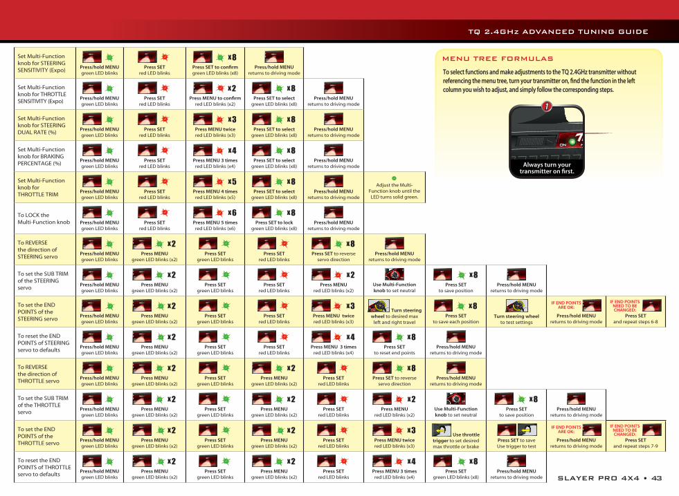
SLAYER PRO 4X4 • 43
TQ 2.4GHz ADVANCED TUNING GUIDE
Set Multi-Function knob for STEERING SENSITIVITY (Expo)
Press/hold MENU green LED blinks
Press SET
red LED blinks
x 8
Press SET to confirm green LED blinks (x8)
Press/hold MENU
returns to driving mode
Set Multi-Function knob for THROTTLE SENSITIVITY (Expo)
Press/hold MENU green LED blinks
Press SET
red LED blinks
x 2
Press MENU to confirm red LED blinks (x2)
x 8
Press SET to select green LED blinks (x8)
Press/hold MENU returns to driving mode
Set Multi-Function knob for STEERING DUAL RATE (%)
Press/hold MENU green LED blinks
Press SET
red LED blinks
x 3
Press MENU twice red LED blinks (x3)
x 8
Press SET to select green LED blinks (x8)
Press/hold MENU returns to driving mode
Set Multi-Function knob for BRAKING PERCENTAGE (%)
Press/hold MENU green LED blinks
Press SET
red LED blinks
x 4
Press MENU 3 times red LED blinks (x4)
x 8
Press SET to select green LED blinks (x8)
Press/hold MENU returns to driving mode
Set Multi-Function knob for THROTTLE TRIM
Press/hold MENU green LED blinks
Press SET
red LED blinks
x 5
Press MENU 4 times red LED blinks (x5)
x 8
Press SET to select green LED blinks (x8)
Press/hold MENU returns to driving mode
Adjust the Multi-Function knob until the LED turns solid green.
To LOCK the Multi-Function knob
Press/hold MENU green LED blinks
Press SET
red LED blinks
x 6
Press MENU 5 times red LED blinks (x6)
x 8
Press SET to lock green LED blinks (x8)
Press/hold MENU returns to driving mode
To REVERSE the direction of STEERING servo
Press/hold MENU green LED blinks
x 2
Press MENUgreen LED blinks (x2)
Press SET
green LED blinks
Press SET
red LED blinks
x 8
Press SET to reverse servo direction
Press/hold MENU returns to driving mode
To set the SUB TRIM of the STEERING servo
Press/hold MENU green LED blinks
x 2
Press MENUgreen LED blinks (x2)
Press SET
green LED blinks
Press SET
red LED blinks
x 2
Press MENU red LED blinks (x2)
Use Multi-Function knob to set neutral
x 8
Press SET to save position
Press/hold MENU returns to driving mode
To set the END POINTS of the STEERING servo
Press/hold MENU green LED blinks
x 2
Press MENU green LED blinks (x2)
Press SET
green LED blinks
Press SET
red LED blinks
x 3
Press MENU twicered LED blinks (x3)
Turn steering wheel to desired max
left and right travel
x 8
Press SET to save each position
Turn steering wheel
to test settings
IF END POINTS ARE OK:
Press/hold MENU returns to driving mode
IF END POINTS NEED TO BE CHANGED:
Press SET and repeat steps 6-8
To reset the END POINTS of STEERING servo to defaults
Press/hold MENU green LED blinks
x 2
Press MENU green LED blinks (x2)
Press SET
green LED blinks
Press SET
red LED blinks
x 4
Press MENU 3 timesred LED blinks (x4)
x 8
Press SET to reset end points
Press/hold MENU returns to driving mode
To REVERSE the direction of THROTTLE servo
Press/hold MENU green LED blinks
x 2
Press MENUgreen LED blinks (x2)
Press SET
green LED blinks
x 2
Press MENUgreen LED blinks (x2)
Press SET
red LED blinks
x 8
Press SET to reverse servo direction
Press/hold MENU returns to driving mode
To set the SUB TRIM of the THROTTLE servo
Press/hold MENU green LED blinks
x 2
Press MENUgreen LED blinks (x2)
Press SET
green LED blinks
x 2
Press MENUgreen LED blinks (x2)
Press SET
red LED blinks
x 2
Press MENU red LED blinks (x2)
Use Multi-Function knob to set neutral
x 8
Press SET to save position
Press/hold MENU returns to driving mode
To set the END POINTS of the THROTTLE servo
Press/hold MENU green LED blinks
x 2
Press MENU green LED blinks (x2)
Press SET
green LED blinks
x 2
Press MENU green LED blinks (x2)
Press SET
red LED blinks
x 3
Press MENU twice red LED blinks (x3)
Use throttle trigger to set desired max throttle or brake
Press SET to saveUse trigger to test
IF END POINTS ARE OK:
Press/hold MENU returns to driving mode
IF END POINTS NEED TO BE CHANGED:
Press SET and repeat steps 7-9
To reset the END POINTS of THROTTLE servo to defaults
Press/hold MENU green LED blinks
x 2
Press MENU green LED blinks (x2)
Press SET
green LED blinks
x 2
Press MENUgreen LED blinks (x2)
Press SET
red LED blinks
x 4
Press MENU 3 times red LED blinks (x4)
x 8
Press SET green LED blinks (x8)
Press/hold MENU returns to driving mode
MENU TREE FORMULAS
To select functions and make adjustments to the TQ 2.4GHz transmitter without referencing the menu tree, turn your transmitter on, find the function in the left column you wish to adjust, and simply follow the corresponding steps.
Always turn yourtransmitter on first.
1

100617 KC1246-R00
1100 Klein Road, Plano Texas 750741-888-TRAXXAS
MODEL 5907
owner’s manual