Embed Size (px)
Citation preview

Water Control Corporation
7150 143rd Ave NW • Ramsey, MN 55303
Phone: 763-427-9638 • Fax: 763-427-5665
www.watercontrolinc.com
© Water Control Corporation
MF Series Commercial Water Softeners
OWNER'S MANUAL
12/22/2017
ModelSeries
Number
Exchange Capacity*(grains)
Flow Rate (gpm) Pipe Size (inches) BackWash(gpm)
Resin(cu ft)
Brine Tank
Capacity (lbs)
Regen.Time(min)
Tank Size (in) Approx.Ship
Weight(lbs)Min 1 Mid 2 Max 3 Cv 7 psid
Cont.15 psid
Peak25 psid Service Drain Resin Salt
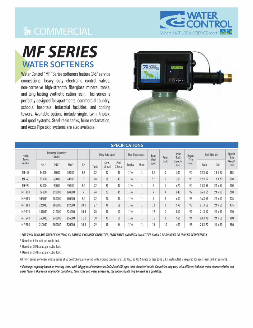
MF-48 34000 48000 52000 8.3 22 32 42 1 ½ 1 3.5 2 300 90 12 X 52 18 X 33 185
MF-60 33000 60000 64000 8 18 28 40 1 ½ 1 3.5 2 300 90 12 X 52 18 X 33 210
MF-90 63000 90000 96000 8.4 22 30 42 1 ½ 1 5 3 670 90 14 X 65 24 x 50 300
MF-120 84000 120000 128000 9 24 33 45 1 ½ 1 7 4 640 92 16 X 65 24 x 50 360
MF-150 105000 150000 160000 8.2 22 30 41 1 ½ 1 7 5 600 94 16 X 65 24 x 50 425
MF-180 126000 180000 192000 10.2 27 40 51 1 ½ 1 12 6 590 90 21 X 62 24 x 50 475
MF-210 147000 210000 224000 10.4 28 40 52 1 ½ 1 12 7 560 92 21 X 62 24 x 50 510
MF-240 168000 240000 256000 11.2 30 42 56 1 ½ 1 15 8 525 94 24 X 72 24 x 50 700
MF-300 210000 300000 320000 10.8 29 40 54 1 ½ 1 15 10 490 96 24 X 72 24 x 50 850
- FOR TWIN TANK AND TRIPLEX SYSTEMS, CV RATNGS, EXCHANGE CAPACITIES, FLOW RATES AND RESIN QUANTITIES SHOULD BE DOUBLED OR TRIPLED RESPECTIVELY.
1 Based on 6 lbs salt per cubic foot.
2 Based on 10 lbs salt per cubic foot.
3 Based on 15 lbs salt per cubic foot.
All “MF” Series softeners utilize series 2850 controllers, pre-wired with 3-prong connectors, 120 VAC, 60 Hz, 5 Amps or less (One G.F.I. wall outlet is required for each resin tank in system).
* Exchange capacity based on treating water with 10 gpg total hardness as CaCo3 and 400 ppm total dissolved solids. Capacities may vary with different influent water characteristics and other factors. Due to varying water conditions, tank sizes and water pressures, the above should only be used as a guideline.
MF SERIESWATER SOFTENERS
Water Control “MF” Series softeners feature 1½” service connections, heavy duty electronic control valves, non-corrosive high-strength fiberglass mineral tanks, and long-lasting synthetic cation resin. This series is perfectly designed for apartments, commercial laundry, schools, hospitals, industrial facilities, and cooling towers. Available options include single, twin, triplex, and quad systems. Steel resin tanks, brine reclamation, and Accu-Pipe skid systems are also available.
SPECIFICATIONS
We have team members throughout the US and Canada who are ready to serve you.To get started, please talk with your local sales representative, or contact our Technical Support Department: 1-866-405-1268 or [email protected]
Water Control Corporation7150 143rd Ave NW • Ramsey, MN 55303
Phone: 763-427-9638 • Fax: 763-427-5665www.watercontrolinc.com
© Water Control Corporation 0317
WITH OVER 45 YEARS OF EXPERIENCE IN THE WATER CONDITIONING AND PLUMBING INDUSTRIES, WATER CONTROL
CAN DESIGN AND MANUFACTURE EQUIPMENT FOR VIRTUALLY ANY APPLICATION. WE OFFER A COMPLETE MENU OF SERVICES, INCLUDING WATER TESTING, SYSTEM
SIZING, BIM MODELING (REVIT™), DELIVERY, SETUP, STARTUP, AND AFTER-MARKET SERVICE PLANS. WE MAINTAIN A UNIQUE FOCUS ON MECHANICAL ENGINEERS,
CONTRACTORS, AND THE PLUMBING INDUSTRY. DEPEND ON US TO PROVIDE QUALITY, INNOVATIVE SOLUTIONS FOR ALL YOUR COMMERCIAL WATER CONDITIONING NEEDS.
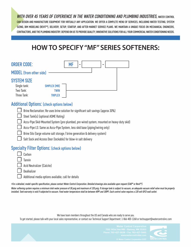
HOW TO SPECIFY “MF” SERIES SOFTENERS:
ORDER CODE:
MODEL (from other side)
SYSTEM SIZESingle tank:Two Tank:Three Tank:
Additional Options: (check options below)☐ Brine Reclamation: Re-uses brine solution for significant salt savings (approx 30%)
☐ Steel Tank(s) (optional ASME Rating)
☐ Accu-Pipe Skid-Mounted System (pre-plumbed, pre-wired system, mounted on heavy-duty skid)
☐ Accu-Pipe LS: Same as Accu-Pipe System, less skid base (piping/wiring only)
☐ Brine Silo (large volume salt storage / brine generation & delivery system)
☐ Salt Sock and Access Door (lockable) for blow-in salt delivery
Specialty Filter Options: (check options below)
☐ Carbon
☐ Tannin
☐ Acid Neutralizer (Calcite)
☐ Dealkalizer
☐ Additional media options available, call for details
*For a detailed, model-specific specification, please contact Water Control Corporation. Detailed drawings also available upon request (CAD™ or Revit™).
Water softening system requires a minimum inlet water pressure of 30 psig and maximum of 120 psig. If storage tank is subject to vacuum, an adequate vacuum relief valve must be properly installed. Tank warranty is void if subjected to vacuum. Feed water temperature shall be between 40⁰F and 100⁰F. Each control valve requires a 120 volt GFCI wall outlet.
SIMPLEX (MR)TWIN
TRIPLEX
MF - -
We have team members throughout the US and Canada who are ready to serve you.To get started, please talk with your local sales representative, or contact our Technical Support Department: 1-866-405-1268 or [email protected]
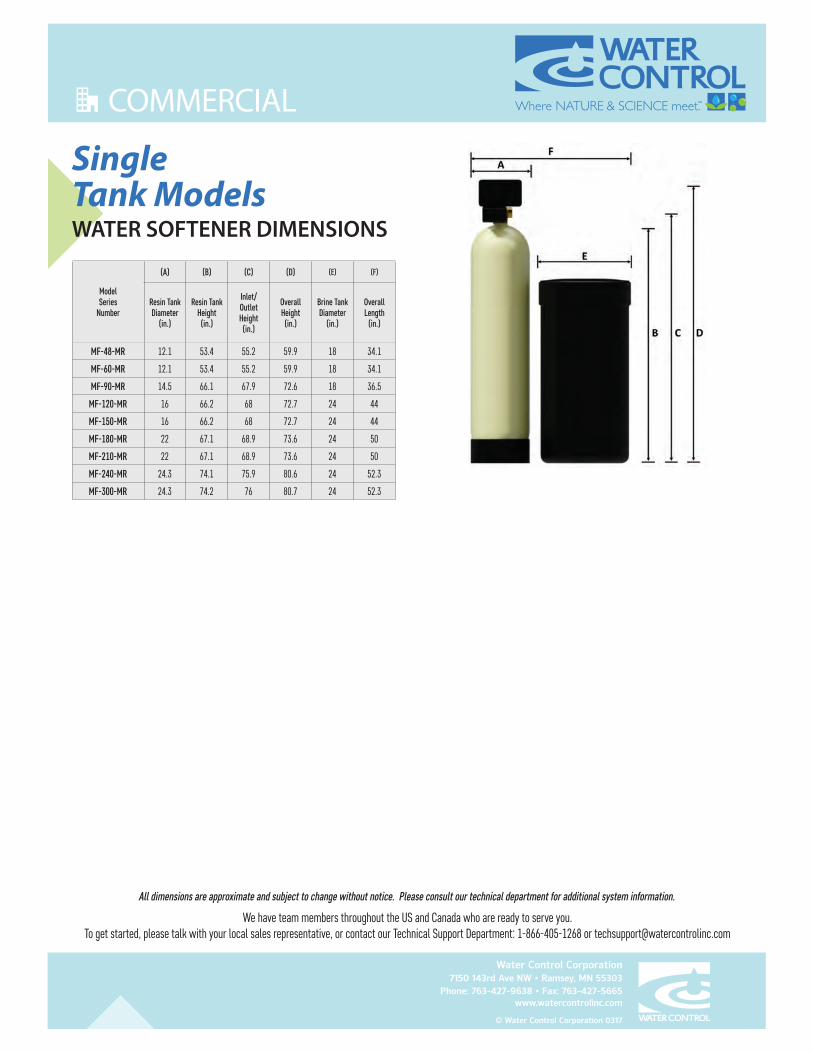
All dimensions are approximate and subject to change without notice. Please consult our technical department for additional system information.
Water Control Corporation7150 143rd Ave NW • Ramsey, MN 55303
Phone: 763-427-9638 • Fax: 763-427-5665www.watercontrolinc.com
© Water Control Corporation 0317
SingleTank ModelsWATER SOFTENER DIMENSIONS
ModelSeries
Number
(A) (B) (C) (D) (E) (F)
Resin Tank Diameter
(in.)
Resin Tank Height (in.)
Inlet/ Outlet Height (in.)
Overall Height (in.)
Brine Tank Diameter
(in.)
Overall Length
(in.)
MF-48-MR 12.1 53.4 55.2 59.9 18 34.1
MF-60-MR 12.1 53.4 55.2 59.9 18 34.1
MF-90-MR 14.5 66.1 67.9 72.6 18 36.5
MF-120-MR 16 66.2 68 72.7 24 44
MF-150-MR 16 66.2 68 72.7 24 44
MF-180-MR 22 67.1 68.9 73.6 24 50
MF-210-MR 22 67.1 68.9 73.6 24 50
MF-240-MR 24.3 74.1 75.9 80.6 24 52.3
MF-300-MR 24.3 74.2 76 80.7 24 52.3
FILTRATION & PROCESS
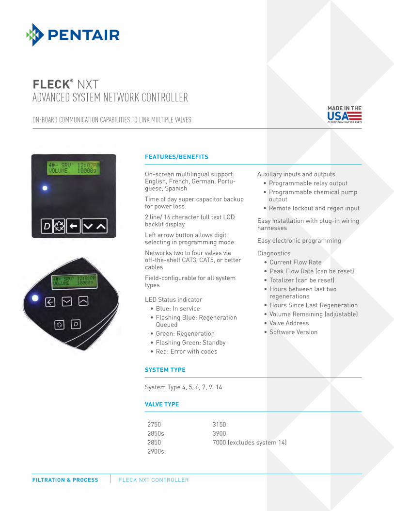
FEATURES/BENEFITS
On-screen multilingual support: English, French, German, Portu-guese, SpanishTime of day super capacitor backup for power loss 2 line/ 16 character full text LCD backlit displayLeft arrow button allows digit selecting in programming modeNetworks two to four valves via off-the-shelf CAT3, CAT5, or better cablesField-configurable for all system types
LED Status indicatorBlue: In serviceFlashing Blue: Regeneration QueuedGreen: RegenerationFlashing Green: StandbyRed: Error with codes
Auxillary inputs and outputsProgrammable relay output Programmable chemical pump outputRemote lockout and regen input
Easy installation with plug-in wiring harnesses
Easy electronic programming
DiagnosticsCurrent Flow RatePeak Flow Rate (can be reset)Totalizer (can be reset)Hours between last two regenerationsHours Since Last RegenerationVolume Remaining (adjustable)Valve AddressSoftware Version
FLECK NXT CONTROLLER
ON-BOARD COMMUNICATION CAPABILITIES TO LINK MULTIPLE VALVES
FLECK® NXT
ADVANCED SYSTEM NETWORK CONTROLLER
SYSTEM TYPE
System Type 4, 5, 6, 7, 9, 14
VALVE TYPE
27502850s28502900s
31503900 7000 (excludes system 14)
FILTRATION & PROCESS5730 NORTH GLEN PARK ROAD, MILWAUKEE, WI 53209P: 262.238.4400 | F: 262.518.4404 | WWW.PENTAIRAQUA.COM | CUSTOMER CARE: 800.279.9404
All Pentair trademarks and logos are owned by Pentair, Inc. or its affiliates. All other registered and unregistered trademarks and logos are the property of their
respective owners. Because we are continuously improving our products and services, Pentair reserves the right to change specifications without prior notice.
Pentair is an equal opportunity employer.
42693 REV B NV13 © 2013 Pentair Residential Filtration, LLC. All Rights Reserved.
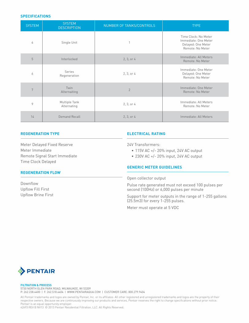
REGENERATION TYPE
Meter Delayed Fixed ReserveMeter ImmediateRemote Signal Start ImmediateTime Clock Delayed
REGENERATION FLOW
DownflowUpflow Fill FirstUpflow Brine First
ELECTRICAL RATING
24V Transformers:115V AC +/- 20% input, 24V AC output230V AC +/- 20% input, 24V AC output
GENERIC METER GUIDELINES
Open collector outputPulse rate generated must not exceed 100 pulses per second (100Hz) or 6,000 pulses per minuteSupport for meter outputs in the range of 1-255 gallons (25.5m3) for every 1-255 pulses. Meter must operate at 5 VDC
SYSTEM SYSTEMDESCRIPTION NUMBER OF TANKS/CONTROLS TYPE
4 Single Unit 1
Time Clock: No MeterImmediate: One Meter
Delayed: One MeterRemote: No Meter
5 Interlocked 2, 3, or 4 Immediate: All MetersRemote: No Meter
6 SeriesRegeneration 2, 3, or 4
Immediate: One MeterDelayed: One MeterRemote: No Meter
7 TwinAlternaiting 2 Immediate: One Meter
Remote: No Meter
9 Multiple TankAlternating 2, 3, or 4 Immediate: All Meters
Remote: No Meter
14 Demand Recall 2, 3, or 4 Immediate: All Meters
SPECIFICATIONS
FILTRATION & PROCESS FLECK 2850 COMMERCIAL CONTROL VALVES
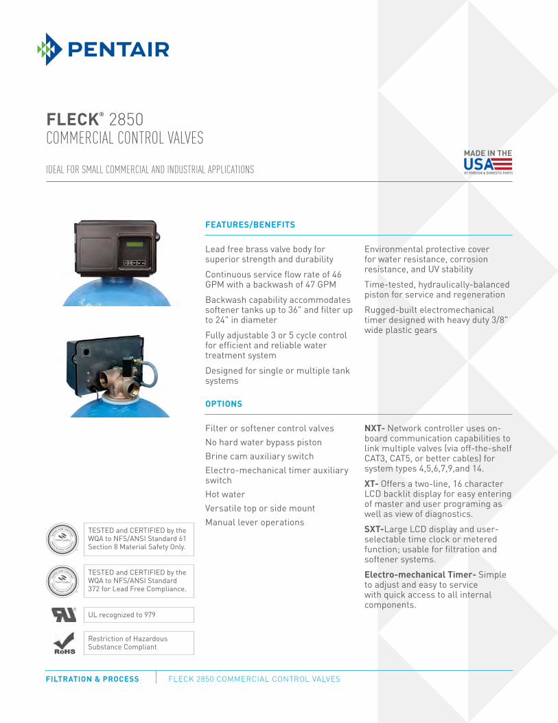
IDEAL FOR SMALL COMMERCIAL AND INDUSTRIAL APPLICATIONS
FLECK® 2850
COMMERCIAL CONTROL VALVES
FEATURES/BENEFITS
Lead free brass valve body for superior strength and durability Continuous service flow rate of 46 GPM with a backwash of 47 GPMBackwash capability accommodates softener tanks up to 36" and filter up to 24" in diameterFully adjustable 3 or 5 cycle control for efficient and reliable water treatment systemDesigned for single or multiple tank systems
Environmental protective cover for water resistance, corrosion resistance, and UV stabilityTime-tested, hydraulically-balanced piston for service and regenerationRugged-built electromechanical timer designed with heavy duty 3/8" wide plastic gears
OPTIONS
Filter or softener control valvesNo hard water bypass pistonBrine cam auxiliary switchElectro-mechanical timer auxiliary switchHot water Versatile top or side mountManual lever operations
NXT- Network controller uses on-board communication capabilities to link multiple valves (via off-the-shelf CAT3, CAT5, or better cables) for system types 4,5,6,7,9,and 14.XT- Offers a two-line, 16 character LCD backlit display for easy entering of master and user programing as well as view of diagnostics.SXT-Large LCD display and user-selectable time clock or metered function; usable for filtration and softener systems.Electro-mechanical Timer- Simple to adjust and easy to service with quick access to all internal components.
TESTED and CERTIFIED by the WQA to NFS/ANSI Standard 61 Section 8 Material Safety Only.
TESTED and CERTIFIED by the WQA to NFS/ANSI Standard 372 for Lead Free Compliance.
Restriction of Hazardous Substance Compliant
UL recognized to 979
FILTRATION & PROCESS5730 NORTH GLEN PARK ROAD, MILWAUKEE, WI 53209P: 262.238.4400 | F: 262.518.4404 | WWW.PENTAIRAQUA.COM | CUSTOMER CARE: 800.279.9404
All Pentair trademarks and logos are owned by Pentair, Inc. or its affiliates. All other registered and unregistered trademarks and logos are the property of their
respective owners. Because we are continuously improving our products and services, Pentair reserves the right to change specifications without prior notice.
Pentair is an equal opportunity employer.
40726 REV D NV13 © 2013 Pentair Residential Filtration, LLC. All Rights Reserved.
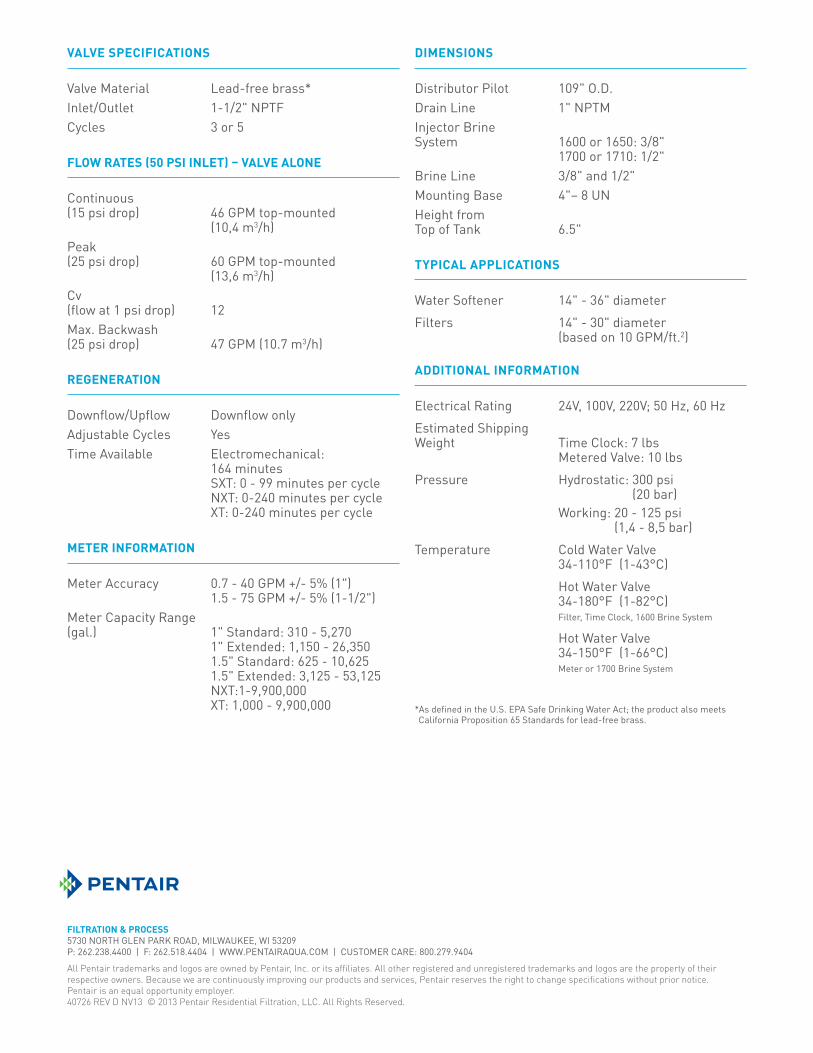
VALVE SPECIFICATIONS
Valve Material Lead-free brass*Inlet/Outlet 1-1/2" NPTFCycles 3 or 5
FLOW RATES (50 PSI INLET) – VALVE ALONE
Continuous (15 psi drop) 46 GPM top-mounted (10,4 m3/h)Peak (25 psi drop) 60 GPM top-mounted (13,6 m3/h)Cv (flow at 1 psi drop) 12Max. Backwash (25 psi drop) 47 GPM (10.7 m3/h)
REGENERATION
Downflow/Upflow Downflow onlyAdjustable Cycles YesTime Available Electromechanical:
164 minutes SXT: 0 - 99 minutes per cycle NXT: 0-240 minutes per cycle XT: 0-240 minutes per cycle
METER INFORMATION
Meter Accuracy 0.7 - 40 GPM +/- 5% (1") 1.5 - 75 GPM +/- 5% (1-1/2")
Meter Capacity Range (gal.) 1" Standard: 310 - 5,270
1" Extended: 1,150 - 26,350 1.5" Standard: 625 - 10,625 1.5" Extended: 3,125 - 53,125 NXT:1-9,900,000 XT: 1,000 - 9,900,000
DIMENSIONS
Distributor Pilot 109" O.D.Drain Line 1" NPTMInjector Brine System 1600 or 1650: 3/8"
1700 or 1710: 1/2"Brine Line 3/8" and 1/2"Mounting Base 4"– 8 UNHeight from Top of Tank 6.5"
TYPICAL APPLICATIONS
Water Softener 14" - 36" diameterFilters 14" - 30" diameter (based on 10 GPM/ft.2)
ADDITIONAL INFORMATION
Electrical Rating 24V, 100V, 220V; 50 Hz, 60 HzEstimated Shipping Weight Time Clock: 7 lbs Metered Valve: 10 lbsPressure Hydrostatic: 300 psi
(20 bar) Working: 20 - 125 psi
(1,4 - 8,5 bar)Temperature Cold Water Valve 34-110°F (1-43°C) Hot Water Valve 34-180°F (1-82°C) Filter, Time Clock, 1600 Brine System
Hot Water Valve 34-150°F (1-66°C) Meter or 1700 Brine System
*As defined in the U.S. EPA Safe Drinking Water Act; the product also meets California Proposition 65 Standards for lead-free brass.
FILTRATION & PROCESSING SOLUTIONS FLECK METERS
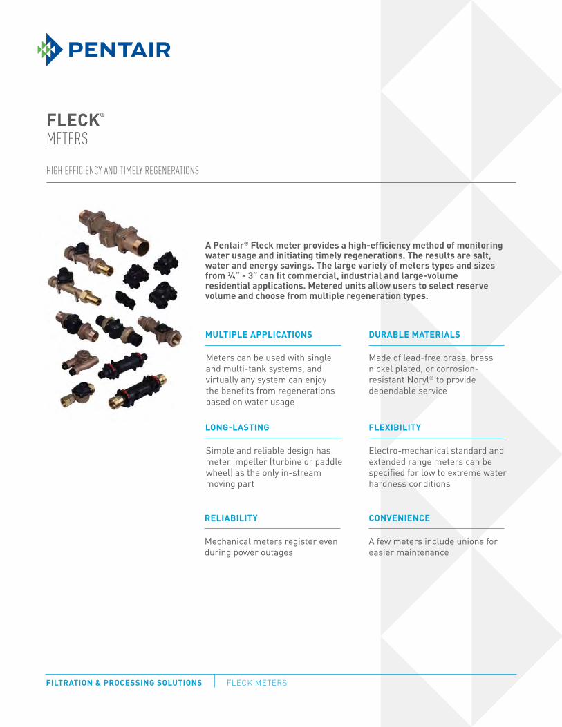
FLECK®
METERS
A Pentair® Fleck meter provides a high-efficiency method of monitoringwater usage and initiating timely regenerations. The results are salt,water and energy savings. The large variety of meters types and sizesfrom ¾” - 3” can fit commercial, industrial and large-volumeresidential applications. Metered units allow users to select reservevolume and choose from multiple regeneration types.
MULTIPLE APPLICATIONS
LONG-LASTING
DURABLE MATERIALS
FLEXIBILITY
CONVENIENCERELIABILITY
HIGH EFFICIENCY AND TIMELY REGENERATIONS
Meters can be used with single and multi-tank systems, and virtually any system can enjoy the benefits from regenerations based on water usage
Simple and reliable design hasmeter impeller (turbine or paddlewheel) as the only in-stream moving part
Made of lead-free brass, brass nickel plated, or corrosion-resistant Noryl® to provide dependable service
Electro-mechanical standard andextended range meters can bespecified for low to extreme waterhardness conditions
A few meters include unions for easier maintenance
Mechanical meters register evenduring power outages
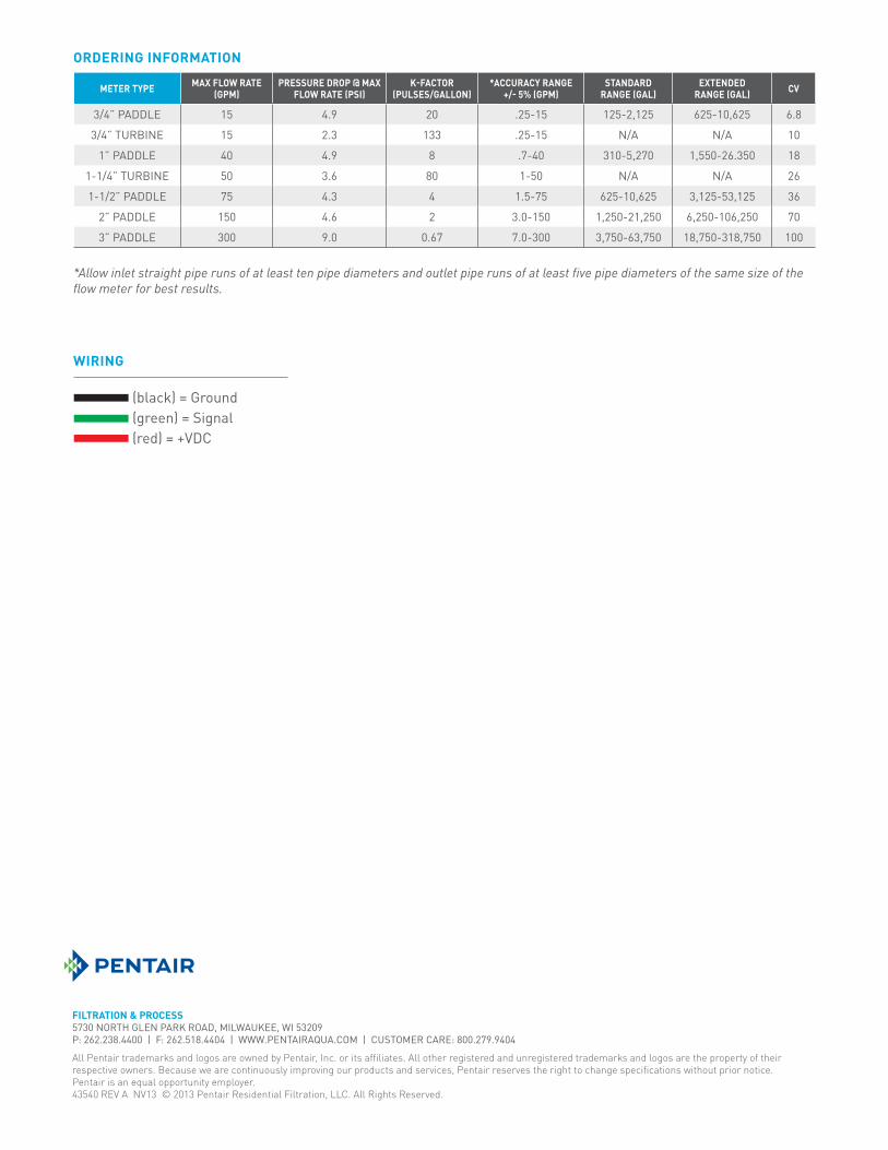
ORDERING INFORMATION
METER TYPE MAX FLOW RATE(GPM)
PRESSURE DROP @ MAX FLOW RATE (PSI)
K-FACTOR (PULSES/GALLON)
*ACCURACY RANGE+/- 5% (GPM)
STANDARD RANGE (GAL)
EXTENDEDRANGE (GAL) CV
3/4” PADDLE 15 4.9 20 .25-15 125-2,125 625-10,625 6.8
3/4” TURBINE 15 2.3 133 .25-15 N/A N/A 10
1” PADDLE 40 4.9 8 .7-40 310-5,270 1,550-26.350 18
1-1/4” TURBINE 50 3.6 80 1-50 N/A N/A 26
1-1/2” PADDLE 75 4.3 4 1.5-75 625-10,625 3,125-53,125 36
2” PADDLE 150 4.6 2 3.0-150 1,250-21,250 6,250-106,250 70
3” PADDLE 300 9.0 0.67 7.0-300 3,750-63,750 18,750-318,750 100
FILTRATION & PROCESS5730 NORTH GLEN PARK ROAD, MILWAUKEE, WI 53209P: 262.238.4400 | F: 262.518.4404 | WWW.PENTAIRAQUA.COM | CUSTOMER CARE: 800.279.9404
All Pentair trademarks and logos are owned by Pentair, Inc. or its affiliates. All other registered and unregistered trademarks and logos are the property of their
respective owners. Because we are continuously improving our products and services, Pentair reserves the right to change specifications without prior notice.
Pentair is an equal opportunity employer.
43540 REV A NV13 © 2013 Pentair Residential Filtration, LLC. All Rights Reserved.
*Allow inlet straight pipe runs of at least ten pipe diameters and outlet pipe runs of at least five pipe diameters of the same size of the flow meter for best results.
WIRING
(black) = Ground(green) = Signal(red) = +VDC
©2013 Pentair Residential Filtration, LLC www.pentairaqua.com
FLECK® 3200 NXTSERVICE MANUAL
2 • FLECK® 3200 NXT Service Manual
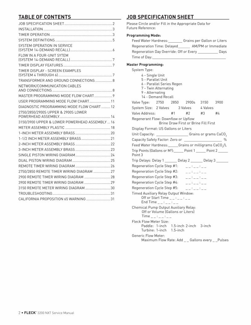
TABLE OF CONTENTSJOB SPECIFICATION SHEET ................................................2INSTALLATION .....................................................................3TIMER OPERATION ..............................................................3SYSTEM DEFINITIONS .........................................................5SYSTEM OPERATION IN SERVICE (SYSTEM 14-DEMAND RECALL) ..........................................6FLOW IN A FOUR-UNIT SYTEM (SYSTEM 14-DEMAND RECALL) ..........................................7TIMER DISPLAY FEATURES .................................................7TIMER DISPLAY - SCREEN EXAMPLES (SYSTEM 4 THROUGH 6) ......................................................7TRANSFORMER AND GROUND CONNECTIONS .................8NETWORK/COMMUNICATION CABLES AND CONNECTIONS ............................................................8MASTER PROGRAMMING MODE FLOW CHART ..................9USER PROGRAMMING MODE FLOW CHART .....................11DIAGNOSTIC PROGRAMMING MODE FLOW CHART .........122750/2850/2900S UPPER & 2900S LOWER POWERHEAD ASSEMBLY...................................................143150/3900 UPPER & LOWER POWERHEAD ASSEMBLY ...16METER ASSEMBLY PLASTIC .............................................181-INCH METER ASSEMBLY BRASS ...................................201-1/2 INCH METER ASSEMBLY BRASS .............................212-INCH METER ASSEMBLY BRASS ...................................223-INCH METER ASSEMBLY BRASS ...................................23SINGLE PISTON WIRING DIAGRAM ...................................24DUAL PISTON WIRING DIAGRAM ......................................25REMOTE TIMER WIRING DIAGRAM ...................................262750/2850 REMOTE TIMER WIRING DIAGRAM .................272900 REMOTE TIMER WIRING DIAGRAM ..........................283900 REMOTE TIMER WIRING DIAGRAM ..........................293150 REMOTE METER WIRING DIAGRAM .........................30TROUBLESHOOTING ..........................................................31CALIFORNIA PROPOSITION 65 WARNING ........................31
JOB SPECIFICATION SHEETPlease Circle and/or Fill in the Appropriate Data for Future Reference:
Programming Mode:Feed Water Hardness: _______ Grains per Gallon or LitersRegeneration Time: Delayed ______ AM/PM or ImmediateRegeneration Day Override: Off or Every __________ DaysTime of Day: _____________________________________
Master Programming: System Type: 4 - Single Unit 5 - Parallel Unit 6 - Parallel Series Regen 7 - Twin Alternating 9 - Alternating 14 - Demand Recall Valve Type: 2750 2850 2900s 3150 3900System Size: 2 Valves 3 Valves 4 ValvesValve Address: #1 #2 #3 #4Regenerant Flow: Downflow or Upflow Brine Draw First or Brine Fill FirstDisplay Format: US Gallons or LitersUnit Capacity: ________________ Grains or grams CaCO3
Capacity Safety Factor: Zero or ___________________ %Feed Water Hardness: _____Grains or milligrams CaCO3/L Trip Points (Gallons or M3):_____ Point 1 _____ Point 2 _____ Point 3Trip Delays: Delay 1 ______ Delay 2 ______ Delay 3 ______Regeneration Cycle Step #1: _ _ : _ _ : _ _Regeneration Cycle Step #2: _ _ : _ _ : _ _Regeneration Cycle Step #3: _ _ : _ _ : _ _Regeneration Cycle Step #4: _ _ : _ _ : _ _Regeneration Cycle Step #5: _ _ : _ _ : _ _Timed Auxiliary Relay Output Window: Off or Start Time _ _ : _ _ : _ _ End Time _ _ : _ _ : _ _Chemical Pump Output Auxiliary Relay: Off or Volume (Gallons or Liters) Time _ _ : _ _ : _ _Fleck Flow Meter Size: Paddle: 1-inch 1.5-inch 2-inch 3-inch Turbine: 1-inch 1.5-inchGeneric Flow Meter: Maximum Flow Rate: Add _ _ Gallons every _ _Pulses
FLECK® 3200 NXT Service Manual • 3
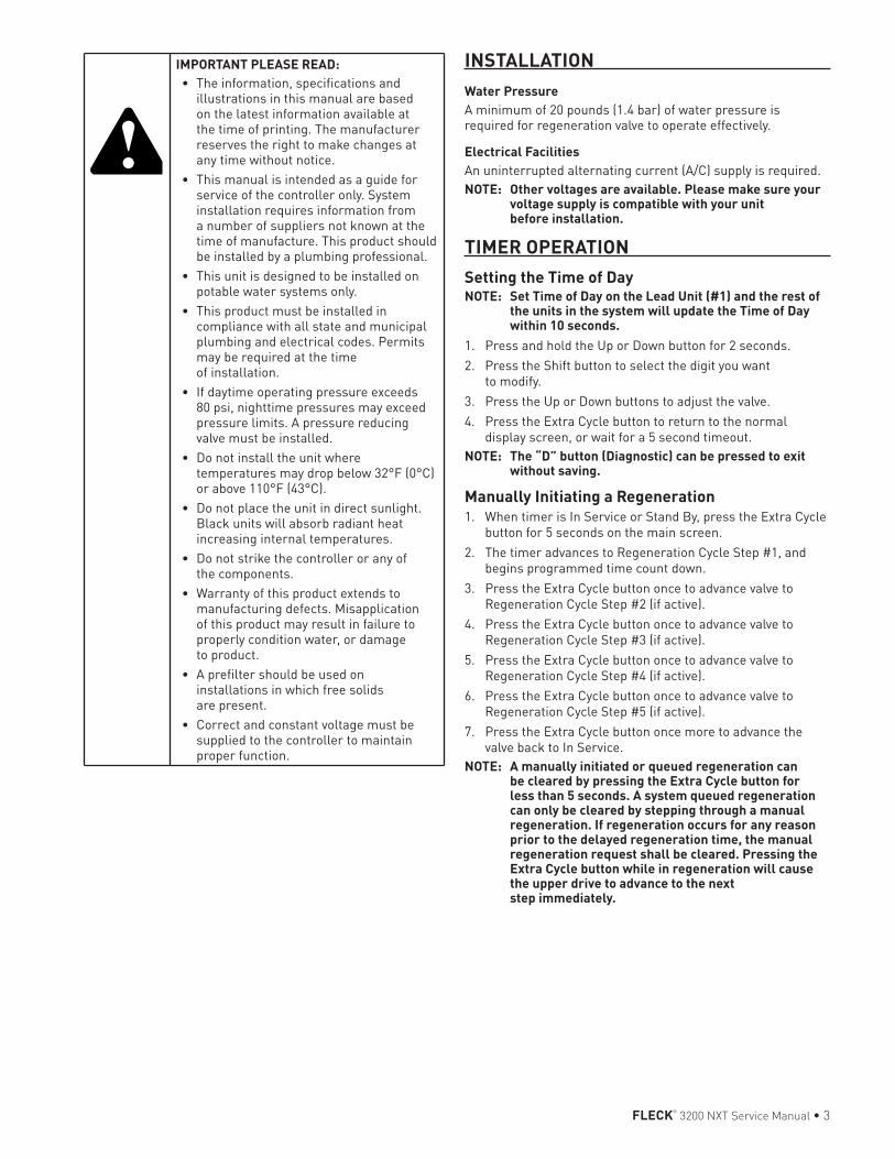
INSTALLATIONWater PressureA minimum of 20 pounds (1.4 bar) of water pressure is required for regeneration valve to operate effectively.
Electrical Facilities An uninterrupted alternating current (A/C) supply is required. NOTE: Other voltages are available. Please make sure your
voltage supply is compatible with your unit before installation.
TIMER OPERATIONSetting the Time of DayNOTE: Set Time of Day on the Lead Unit (#1) and the rest of
the units in the system will update the Time of Day within 10 seconds.
1. Press and hold the Up or Down button for 2 seconds.2. Press the Shift button to select the digit you want
to modify.3. Press the Up or Down buttons to adjust the valve.4. Press the Extra Cycle button to return to the normal
display screen, or wait for a 5 second timeout.NOTE: The “D” button (Diagnostic) can be pressed to exit
without saving.
Manually Initiating a Regeneration1. When timer is In Service or Stand By, press the Extra Cycle
button for 5 seconds on the main screen.2. The timer advances to Regeneration Cycle Step #1, and
begins programmed time count down.3. Press the Extra Cycle button once to advance valve to
Regeneration Cycle Step #2 (if active).4. Press the Extra Cycle button once to advance valve to
Regeneration Cycle Step #3 (if active).5. Press the Extra Cycle button once to advance valve to
Regeneration Cycle Step #4 (if active).6. Press the Extra Cycle button once to advance valve to
Regeneration Cycle Step #5 (if active).7. Press the Extra Cycle button once more to advance the
valve back to In Service.NOTE: A manually initiated or queued regeneration can
be cleared by pressing the Extra Cycle button for less than 5 seconds. A system queued regeneration can only be cleared by stepping through a manual regeneration. If regeneration occurs for any reason prior to the delayed regeneration time, the manual regeneration request shall be cleared. Pressing the Extra Cycle button while in regeneration will cause the upper drive to advance to the next step immediately.
IMPORTANT PLEASE READ: • The information, specifications and
illustrations in this manual are based on the latest information available at the time of printing. The manufacturer reserves the right to make changes at any time without notice.
• This manual is intended as a guide for service of the controller only. System installation requires information from a number of suppliers not known at the time of manufacture. This product should be installed by a plumbing professional.
• This unit is designed to be installed on potable water systems only.
• This product must be installed in compliance with all state and municipal plumbing and electrical codes. Permits may be required at the time of installation.
• If daytime operating pressure exceeds 80 psi, nighttime pressures may exceed pressure limits. A pressure reducing valve must be installed.
• Do not install the unit where temperatures may drop below 32°F (0°C) or above 110°F (43°C).
• Do not place the unit in direct sunlight. Black units will absorb radiant heat increasing internal temperatures.
• Do not strike the controller or any of the components.
• Warranty of this product extends to manufacturing defects. Misapplication of this product may result in failure to properly condition water, or damage to product.
• A prefilter should be used on installations in which free solids are present.
• Correct and constant voltage must be supplied to the controller to maintain proper function.
4 • FLECK® 3200 NXT Service Manual
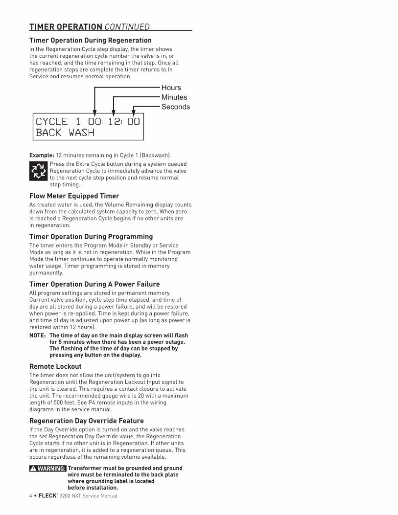
Timer Operation During RegenerationIn the Regeneration Cycle step display, the timer shows the current regeneration cycle number the valve is in, or has reached, and the time remaining in that step. Once all regeneration steps are complete the timer returns to In Service and resumes normal operation.
Example: 12 minutes remaining in Cycle 1 (Backwash)Press the Extra Cycle button during a system queued Regeneration Cycle to immediately advance the valve to the next cycle step position and resume normal step timing.
Flow Meter Equipped TimerAs treated water is used, the Volume Remaining display counts down from the calculated system capacity to zero. When zero is reached a Regeneration Cycle begins if no other units are in regeneration.
Timer Operation During ProgrammingThe timer enters the Program Mode in Standby or Service Mode as long as it is not in regeneration. While in the Program Mode the timer continues to operate normally monitoring water usage. Timer programming is stored in memory permanently.
Timer Operation During A Power FailureAll program settings are stored in permanent memory. Current valve position, cycle step time elapsed, and time of day are all stored during a power failure, and will be restored when power is re-applied. Time is kept during a power failure, and time of day is adjusted upon power up (as long as power is restored within 12 hours).NOTE: The time of day on the main display screen will flash
for 5 minutes when there has been a power outage. The flashing of the time of day can be stopped by pressing any button on the display.
Remote Lockout The timer does not allow the unit/system to go into Regeneration until the Regeneration Lockout Input signal to the unit is cleared. This requires a contact closure to activate the unit. The recommended gauge wire is 20 with a maximum length of 500 feet. See P4 remote inputs in the wiring diagrams in the service manual.
Regeneration Day Override Feature If the Day Override option is turned on and the valve reaches the set Regeneration Day Override value, the Regeneration Cycle starts if no other unit is in Regeneration. If other units are in regeneration, it is added to a regeneration queue. This occurs regardless of the remaining volume available.
WARNING: Transformer must be grounded and ground wire must be terminated to the back plate where grounding label is located before installation.
TIMER OPERATION CONTINUED
FLECK® 3200 NXT Service Manual • 5
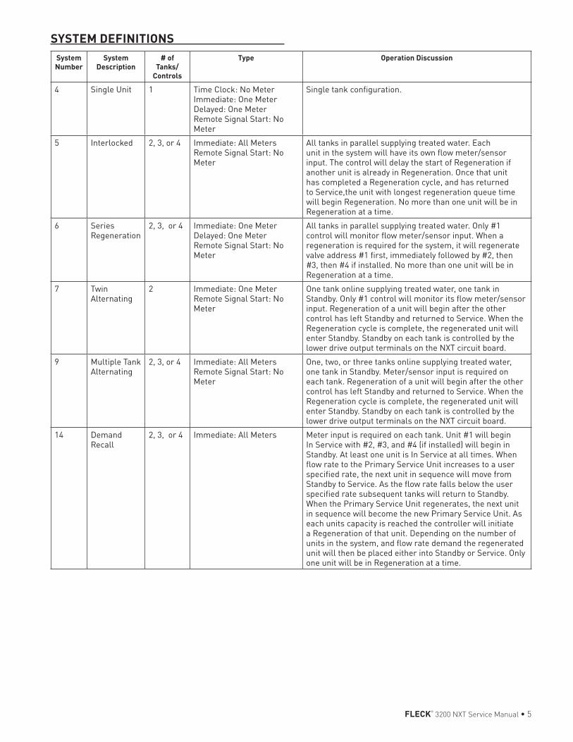
SYSTEM DEFINITIONSSystem Number
System Description
# of Tanks/
Controls
Type Operation Discussion
4 Single Unit 1 Time Clock: No MeterImmediate: One MeterDelayed: One MeterRemote Signal Start: No Meter
Single tank configuration.
5 Interlocked 2, 3, or 4 Immediate: All MetersRemote Signal Start: No Meter
All tanks in parallel supplying treated water. Each unit in the system will have its own flow meter/sensor input. The control will delay the start of Regeneration if another unit is already in Regeneration. Once that unit has completed a Regeneration cycle, and has returned to Service,the unit with longest regeneration queue time will begin Regeneration. No more than one unit will be in Regeneration at a time.
6 Series Regeneration
2, 3, or 4 Immediate: One MeterDelayed: One MeterRemote Signal Start: No Meter
All tanks in parallel supplying treated water. Only #1 control will monitor flow meter/sensor input. When a regeneration is required for the system, it will regenerate valve address #1 first, immediately followed by #2, then #3, then #4 if installed. No more than one unit will be in Regeneration at a time.
7 Twin Alternating
2 Immediate: One MeterRemote Signal Start: No Meter
One tank online supplying treated water, one tank in Standby. Only #1 control will monitor its flow meter/sensor input. Regeneration of a unit will begin after the other control has left Standby and returned to Service. When the Regeneration cycle is complete, the regenerated unit will enter Standby. Standby on each tank is controlled by the lower drive output terminals on the NXT circuit board.
9 Multiple Tank Alternating
2, 3, or 4 Immediate: All MetersRemote Signal Start: No Meter
One, two, or three tanks online supplying treated water, one tank in Standby. Meter/sensor input is required on each tank. Regeneration of a unit will begin after the other control has left Standby and returned to Service. When the Regeneration cycle is complete, the regenerated unit will enter Standby. Standby on each tank is controlled by the lower drive output terminals on the NXT circuit board.
14 Demand Recall
2, 3, or 4 Immediate: All Meters Meter input is required on each tank. Unit #1 will begin In Service with #2, #3, and #4 (if installed) will begin in Standby. At least one unit is In Service at all times. When flow rate to the Primary Service Unit increases to a user specified rate, the next unit in sequence will move from Standby to Service. As the flow rate falls below the user specified rate subsequent tanks will return to Standby. When the Primary Service Unit regenerates, the next unit in sequence will become the new Primary Service Unit. As each units capacity is reached the controller will initiate a Regeneration of that unit. Depending on the number of units in the system, and flow rate demand the regenerated unit will then be placed either into Standby or Service. Only one unit will be in Regeneration at a time.
6 • FLECK® 3200 NXT Service Manual
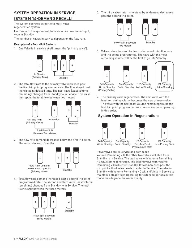
SYSTEM OPERATION IN SERVICE (SYSTEM 14-DEMAND RECALL)The system operates as part of a multi-valve regeneration system.Each valve in the system will have an active flow meter input, even in Standby.The number of valves in service depends on the flow rate.
Examples of a Four-Unit System:1. One Valve is in service at all times (the “primary valve”).
In Service (Primary Tank) Standby
1 2 3 4
2. The total flow rate to the primary valve increased past the first trip point programmed rate. The flow stayed past the trip point delayed time. The next valve (least volume remaining) changes from Standby to In Service. This valve then splits the total flow between two meters.
In Service
1 2 3 4
StandbyFirst Trip Point (Primary Valve)
Total Flow Split Between Two Meters
3. The flow rate demand decreased below the first trip point. The valve returns to Standby.
Standby
Flow Rate Demand Below First Trip Point
(Primary Valve)
1 2 3 4
4. Total flow rate demand increased past a second trip point programmed rate. The second and third valve (least volume remaining) changes from Standby to In Service. The total flow is split between the three meters.
Standby
Flow Split Between Three Meters
1 2 3 4
5. The third valves returns to stand by as demand decreases past the second trip point.
StandbyFlow Split Between Two Meters
1 2 3 4
6. Valves return to stand by due to decreased total flow rate and trip points programmed. The valve with the most remaining volume will be the first to go into Standby.
Full Capacity 4th in Standby (Primary Valve)
3/4 Capacity 3rd in Standby
1 2 3 4
1/2 Capacity 2nd in Standby
1/4 Capacity 1st in Standby
7. The primary valve regenerates. The next valve with the least remaining volume becomes the new primary valve. The valve with the next least volume remaining will be the first trip point programmed rate. Valves continue operating in this order.
Full Capacity 4th in Standby
3/4 Capacity 3rd in Standby
1 2 3 4
1/2 Capacity First Trip Point
Programmed Rate
1/4 Capacity New Primary Tank
System Operation in Regeneration:
If two valves are In Service and both reach Volume Remaining = 0, the other two valves will shift from Standby to In Service. The lead valve with Volume Remaining = 0 will start regeneration. The second valve with Volume Remaining = 0 will enter Standby. If flow increases past the trip point a third valve needs to enter In Service. The valve in Standby with Volume Remaining = 0 will shift into In Service to maintain a steady flow. Operating for extended periods in this mode may degrade the water quality.
FLECK® 3200 NXT Service Manual • 7
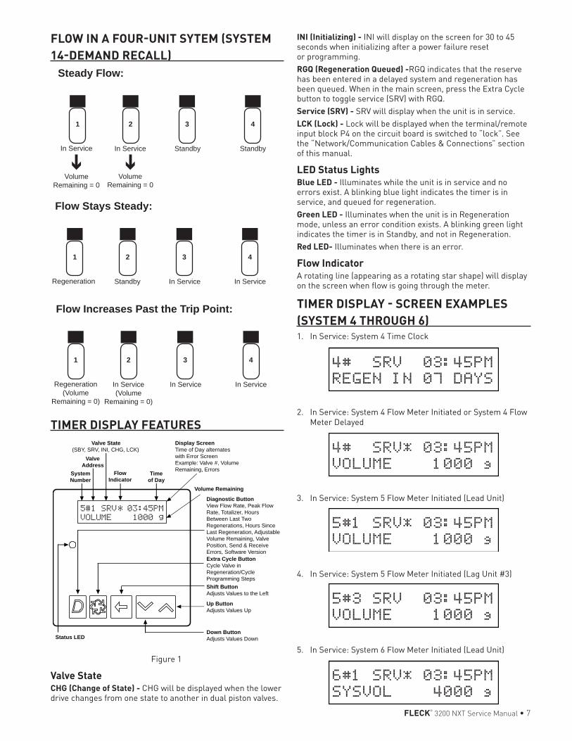
FLOW IN A FOUR-UNIT SYTEM (SYSTEM 14-DEMAND RECALL)
In Service In Service
1 2 3 4
Standby Standby
Steady Flow:
Volume Remaining = 0
Volume Remaining = 0
Regeneration (Volume
Remaining = 0)
In Service (Volume
Remaining = 0)
1 2 3 4
In Service In Service
Flow Increases Past the Trip Point:
Regeneration Standby
1 2 3 4
In Service In Service
Flow Stays Steady:
TIMER DISPLAY FEATURES
System Number
Valve Address
Valve State (SBY, SRV, INI, CHG, LCK)
Flow Indicator
Time of Day
Shift ButtonAdjusts Values to the Left
Up Button Adjusts Values Up
Down Button Adjusts Values Down
Volume Remaining
Status LED
Display ScreenTime of Day alternates with Error Screen Example: Valve #, Volume Remaining, Errors
Diagnostic ButtonView Flow Rate, Peak Flow Rate, Totalizer, Hours Between Last Two Regenerations, Hours Since Last Regeneration, Adjustable Volume Remaining, Valve Position, Send & Receive Errors, Software VersionExtra Cycle ButtonCycle Valve in Regeneration/Cycle Programming Steps
Figure 1
Valve StateCHG (Change of State) - CHG will be displayed when the lower drive changes from one state to another in dual piston valves.
INI (Initializing) - INI will display on the screen for 30 to 45 seconds when initializing after a power failure reset or programming.RGQ (Regeneration Queued) -RGQ indicates that the reserve has been entered in a delayed system and regeneration has been queued. When in the main screen, press the Extra Cycle button to toggle service (SRV) with RGQ.Service (SRV) - SRV will display when the unit is in service.LCK (Lock) - Lock will be displayed when the terminal/remote input block P4 on the circuit board is switched to “lock”. See the “Network/Communication Cables & Connections” section of this manual.
LED Status LightsBlue LED - Illuminates while the unit is in service and no errors exist. A blinking blue light indicates the timer is in service, and queued for regeneration.Green LED - Illuminates when the unit is in Regeneration mode, unless an error condition exists. A blinking green light indicates the timer is in Standby, and not in Regeneration.Red LED- Illuminates when there is an error.
Flow IndicatorA rotating line (appearing as a rotating star shape) will display on the screen when flow is going through the meter.
TIMER DISPLAY - SCREEN EXAMPLES (SYSTEM 4 THROUGH 6)1. In Service: System 4 Time Clock
4# SRV 03:45PM
REGEN IN 07 DAYS
2. In Service: System 4 Flow Meter Initiated or System 4 Flow Meter Delayed
4# SRV* 03:45PM
VOLUME 1000 g
3. In Service: System 5 Flow Meter Initiated (Lead Unit)
5#1 SRV* 03:45PM
VOLUME 1000 g
4. In Service: System 5 Flow Meter Initiated (Lag Unit #3)
5#3 SRV 03:45PM
VOLUME 1000 g
5. In Service: System 6 Flow Meter Initiated (Lead Unit)
6#1 SRV* 03:45PM
SYSVOL 4000 g
8 • FLECK® 3200 NXT Service Manual
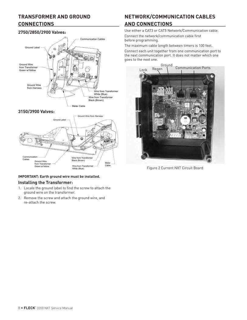
TRANSFORMER AND GROUND CONNECTIONS2750/2850/2900 Valves:
3150/3900 Valves:
IMPORTANT: Earth ground wire must be installed.Installing the Transformer:1. Locate the ground label to find the screw to attach the
ground wire on the transformer.2. Remove the screw and attach the ground wire, and
re-attach the screw.
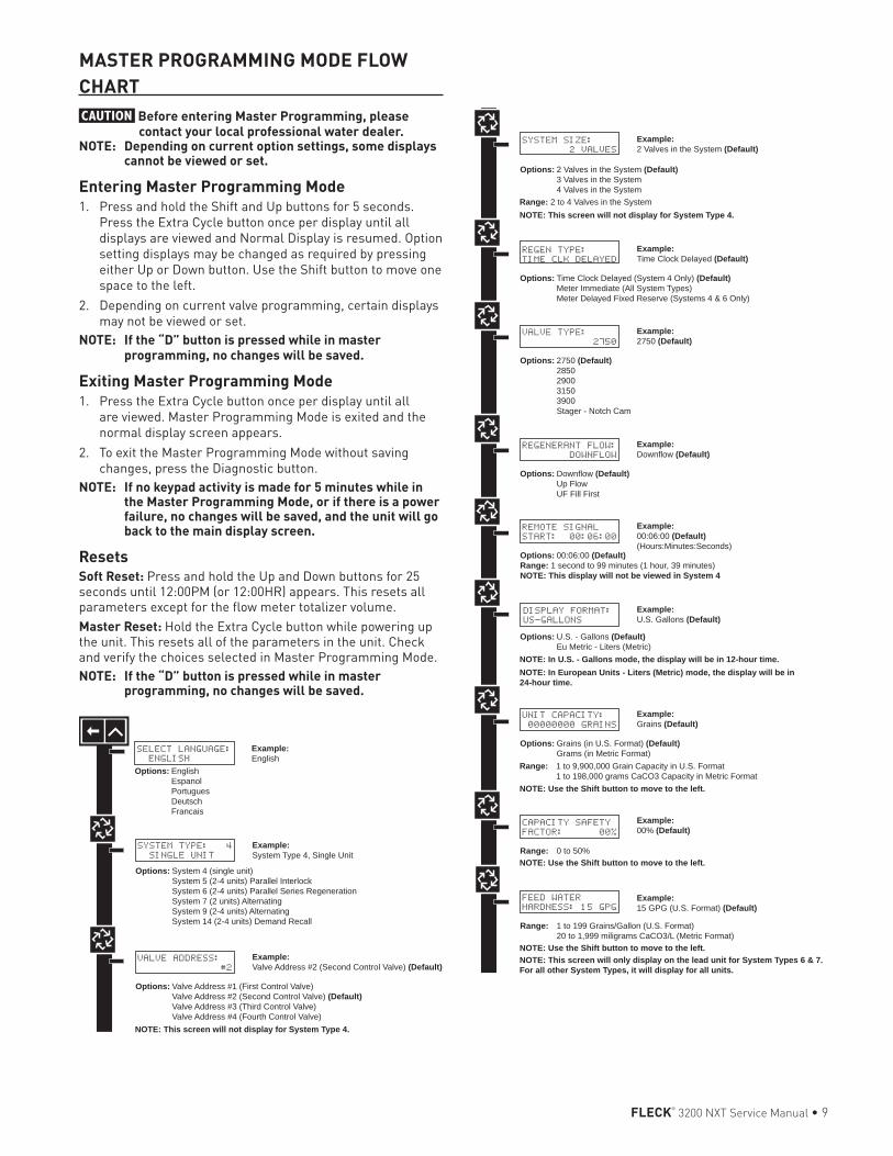
NETWORK/COMMUNICATION CABLES AND CONNECTIONSUse either a CAT3 or CAT5 Network/Communication cable.Connect the network/communication cable first before programming.The maximum cable length between timers is 100 feet.Connect each unit together from one communication port to the next communication port. It does not matter which one goes to the next one.
Communication PortsGround
Lock Regen
Figure 2 Current NXT Circuit Board
FLECK® 3200 NXT Service Manual • 9
VALVE ADDRESS:
#2
Options: Valve Address #1 (First Control Valve) Valve Address #2 (Second Control Valve) (Default) Valve Address #3 (Third Control Valve) Valve Address #4 (Fourth Control Valve)
SYSTEM TYPE: 4
SINGLE UNIT
Options: System 4 (single unit) System 5 (2-4 units) Parallel Interlock System 6 (2-4 units) Parallel Series Regeneration System 7 (2 units) Alternating System 9 (2-4 units) Alternating System 14 (2-4 units) Demand Recall
Example:System Type 4, Single Unit
Example:Valve Address #2 (Second Control Valve) (Default)
Example:U.S. Gallons (Default)
SELECT LANGUAGE:
ENGLISH
Options: English Espanol Portugues Deutsch Francais
Example:English
VALVE TYPE:
2750
Options: 2750 (Default) 2850 2900 3150 3900 Stager - Notch Cam
Example:2750 (Default)
REGEN TYPE:
TIME CLK DELAYED
Options: Time Clock Delayed (System 4 Only) (Default) Meter Immediate (All System Types) Meter Delayed Fixed Reserve (Systems 4 & 6 Only)
Example:Time Clock Delayed (Default)
REGENERANT FLOW:
DOWNFLOW
Options: Downflow (Default) Up Flow UF Fill First
Example:Downflow (Default)
REMOTE SIGNAL
START: 00:06:00
Options: 00:06:00 (Default)Range: 1 second to 99 minutes (1 hour, 39 minutes)NOTE: This display will not be viewed in System 4
Example:00:06:00 (Default)(Hours:Minutes:Seconds)
NOTE: This screen will not display for System Type 4.
SYSTEM SIZE:
2 VALVES
Options: 2 Valves in the System (Default) 3 Valves in the System 4 Valves in the System
Example:2 Valves in the System (Default)
Range: 2 to 4 Valves in the SystemNOTE: This screen will not display for System Type 4.
DISPLAY FORMAT:
US-GALLONS
Options: U.S. - Gallons (Default) Eu Metric - Liters (Metric)
NOTE: In European Units - Liters (Metric) mode, the display will be in 24-hour time.
NOTE: In U.S. - Gallons mode, the display will be in 12-hour time.
UNIT CAPACITY:
00000000 GRAINS
Options: Grains (in U.S. Format) (Default) Grams (in Metric Format)
Example:Grains (Default)
NOTE: Use the Shift button to move to the left.
Range: 1 to 9,900,000 Grain Capacity in U.S. Format 1 to 198,000 grams CaCO3 Capacity in Metric Format
Example:00% (Default)
CAPACITY SAFETY
FACTOR: 00%
Range: 0 to 50%NOTE: Use the Shift button to move to the left.
FEED WATER
HARDNESS: 15 GPG
Range: 1 to 199 Grains/Gallon (U.S. Format) 20 to 1,999 miligrams CaCO3/L (Metric Format)
Example:15 GPG (U.S. Format) (Default)
NOTE: Use the Shift button to move to the left.NOTE: This screen will only display on the lead unit for System Types 6 & 7.For all other System Types, it will display for all units.
TRIP POINT 1:
000 gpm
NOTE: Display will not appear unless timer is programmed as valve position #1. Use the Shift button to change each decimal position.
REGENERATION DAY
OVERRIDE:OFF
Example:Off (Default)On (Default for time clock)
REGENERATION DAY
OVERRIDE:01 DAYS
Options: Off (Default for meter) or On
Example:1 Day
Range: 1 to 99 Days
REGENERATION
TIME: 02:00AM
Example:2:00 A.M. (Default)
Options: A.M. (U.S. Format) HR (Metric Format)NOTE: Regeneration time will not appear unless Regeneration Day Override is on.
CYCLE 1 00:00:00
BACK WASH
Example:Cycle 1 in Back Wash Mode
Options: Regeneration Cycle Step #1 Regeneration Cycle Step #2 Regeneration Cycle Step #3 Regeneration Cycle Step #4 Regeneration Cycle Step #5NOTE: Please refer to the “Regenerant Flow Default Cycle Steps & Times” in the Master Programming Mode section of the manual.NOTE: If Stager is chosen for Valve Type, the Regeneration Cycle Step description will not display.
AUXILIARY RELAY:
DISABLED
Example:Auxiliary Relay is Disabled
Options: Enabled Disabled (Default)
AUX RELAY OUTPUT
START 1 00:00:00
Example:Auxiliary Relay Output in Start 1 at 0 hours, 0 minutes, & 0 seconds
Range: 00:00:00 to 18:00:00NOTE: Only displayed if Auxiliary Relay is enabled in previous screen. Auxiliary Relay will only display if Chemical Pump is OFF for System Types 6 & 7.
AUX RELAY OUTPUT
END 1 00:00:00
Example:Auxiliary Relay Output in End 1 at 0 hours, 0 minutes, & 0 seconds
Range: 00:00:00 to 18:00:00
CHEMICAL PUMP:
DISABLED
Example:Chemical Pump is Disabled
Options: Enabled Disabled (Default)NOTE: This screen will only display on the lead unit for System Types 6 & 7. For all other System Types, it will display for all units.
CPO AUX RELAY
VOLUME: 000 g
Example:Energize Chemical Pump Relay Every 50 GallonsEnergize Chemical Pump Relay Every 200 L
Range: 1 to 999 gallons in U.S. Format 1 to 9.999 L in Metric FormatNOTE: Only displayed on units that physically have a meter (Lead always has a meter). Only shown if Auxiliary Relay is disabled on System Types 6 & 7.
CPO AUX RELAY
TIME: 00:00:00
Example:Each Time the Chemical Pump Relay is on, Run for 30 Seconds (00:00:30)
Range: 00:00:00 to 02:00:00
FLOW METER:
1.0 PADDLE
Example:1.0 Paddle Flow Meter
Options: 1.0 Paddle (Fleck) 1.0 Turbine (Fleck) 1.5 Paddle (Fleck) 1.5 Turbine (Fleck) 2.0 Paddle (Fleck) 3.0 Paddle (Fleck) Generic (Non-Fleck)NOTES: Default flow meter type is based on the valve type. This screen will only display on the lead unit for System Types 6 & 7. All other system types it will display for all units.
MAXIMUM FLOW
RATE: 0000 gpm
Example:Maximum Flow Rate of 0 gpm
Range: 20 - 2,000 gpm (U.S. Format) 20 - 200.0 L (Metric Format) NOTE: Only displayed if “Generic” is chosen for the flow meter.
Range: 1 - 255Gallons (U.S. Format) 0.1 - 09.9 L (Metric Format) Pulses: 1 - 255
Options: Gallons (U.S. Format) Liters (Metric Format)
ADD 01 GALLONS
EVERY 001 PULSES
Example:Add 1 Gallon for Each Pulse in U.S. Format
NOTE: Only displayed if “Generic” is chosen for the flow meter.
PROGRAMMING UNIT
PLEASE WAIT...
Example:Master Programming Mode is Exiting
NOTE: Display will not appear unless timer is programmed as valve position #1. Use the Shift button to move one space to the left.
TRIP DELAY 1:
30 SECONDS
NOTE: Display will not appear unless timer is programmed as valve position #1. System size must be 3 or 4 to appear. Use the Shift button to move one space to the left.
TRIP DELAY 2:
30 SECONDS
NOTE: Display will not appear unless timer is programmed as valve position #1. System size must be 3 or 4 to appear. Use the Shift button to move one space to the left.
TRIP POINT 2:
gpm
NOTE: Display will not appear unless timer is programmed as valve position #1. System size must be 4 to appear. Use the Shift button to move one space to the left.
TRIP POINT 3:
gpm
NOTE: Display will not appear unless timer is programmed as valve position #1. System size must be 4 to appear. Use the Shift button to move one space to the left.
TRIP DELAY 3:
30 SECONDS
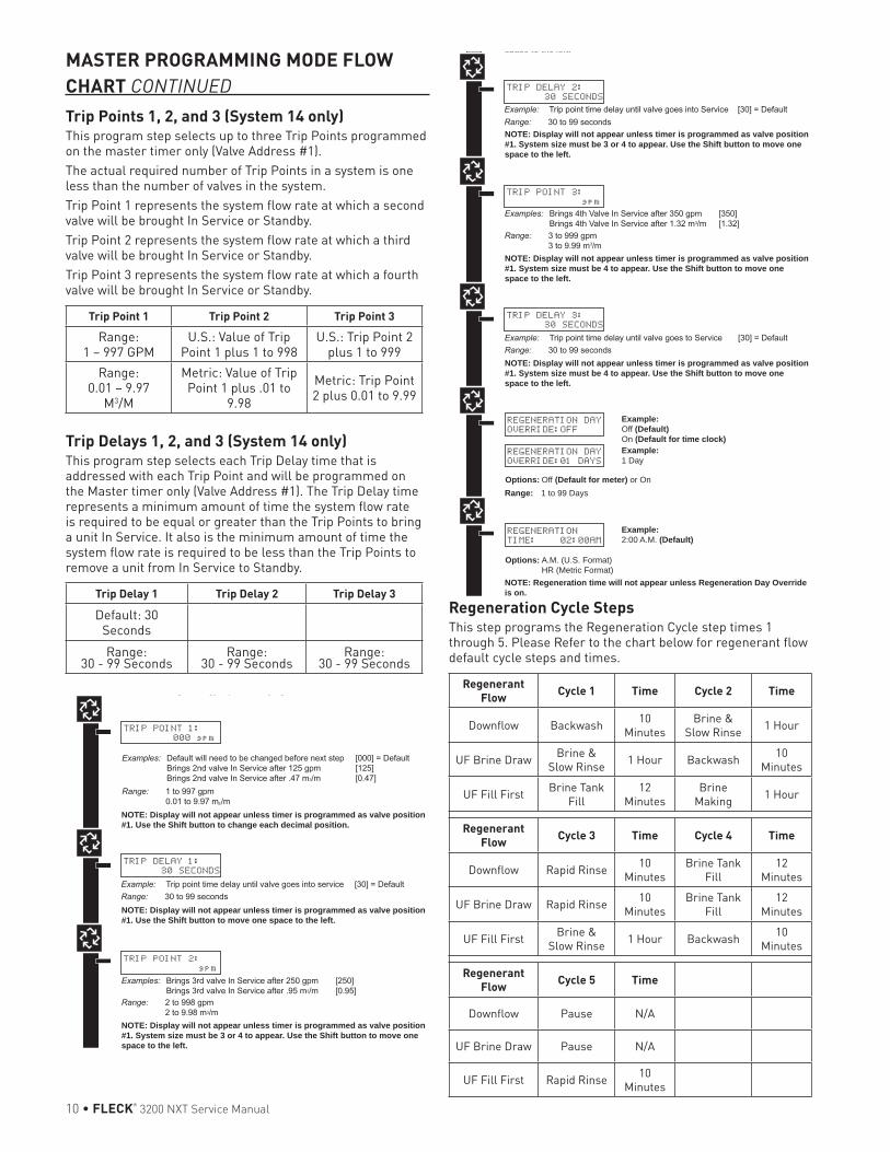
MASTER PROGRAMMING MODE FLOW CHARTCAUTION Before entering Master Programming, please
contact your local professional water dealer.NOTE: Depending on current option settings, some displays
cannot be viewed or set.
Entering Master Programming Mode1. Press and hold the Shift and Up buttons for 5 seconds.
Press the Extra Cycle button once per display until all displays are viewed and Normal Display is resumed. Option setting displays may be changed as required by pressing either Up or Down button. Use the Shift button to move one space to the left.
2. Depending on current valve programming, certain displays may not be viewed or set.
NOTE: If the “D” button is pressed while in master programming, no changes will be saved.
Exiting Master Programming Mode1. Press the Extra Cycle button once per display until all
are viewed. Master Programming Mode is exited and the normal display screen appears.
2. To exit the Master Programming Mode without saving changes, press the Diagnostic button.
NOTE: If no keypad activity is made for 5 minutes while in the Master Programming Mode, or if there is a power failure, no changes will be saved, and the unit will go back to the main display screen.
ResetsSoft Reset: Press and hold the Up and Down buttons for 25 seconds until 12:00PM (or 12:00HR) appears. This resets all parameters except for the flow meter totalizer volume.Master Reset: Hold the Extra Cycle button while powering up the unit. This resets all of the parameters in the unit. Check and verify the choices selected in Master Programming Mode.NOTE: If the “D” button is pressed while in master
programming, no changes will be saved.
VALVE ADDRESS:
#2
Options: Valve Address #1 (First Control Valve) Valve Address #2 (Second Control Valve) (Default) Valve Address #3 (Third Control Valve) Valve Address #4 (Fourth Control Valve)
SYSTEM TYPE: 4
SINGLE UNIT
Options: System 4 (single unit) System 5 (2-4 units) Parallel Interlock System 6 (2-4 units) Parallel Series Regeneration System 7 (2 units) Alternating System 9 (2-4 units) Alternating System 14 (2-4 units) Demand Recall
Example:System Type 4, Single Unit
Example:Valve Address #2 (Second Control Valve) (Default)
Example:U.S. Gallons (Default)
SELECT LANGUAGE:
ENGLISH
Options: English Espanol Portugues Deutsch Francais
Example:English
VALVE TYPE:
2750
Options: 2750 (Default) 2850 2900 3150 3900 Stager - Notch Cam
Example:2750 (Default)
REGEN TYPE:
TIME CLK DELAYED
Options: Time Clock Delayed (System 4 Only) (Default) Meter Immediate (All System Types) Meter Delayed Fixed Reserve (Systems 4 & 6 Only)
Example:Time Clock Delayed (Default)
REGENERANT FLOW:
DOWNFLOW
Options: Downflow (Default) Up Flow UF Fill First
Example:Downflow (Default)
REMOTE SIGNAL
START: 00:06:00
Options: 00:06:00 (Default)Range: 1 second to 99 minutes (1 hour, 39 minutes)NOTE: This display will not be viewed in System 4
Example:00:06:00 (Default)(Hours:Minutes:Seconds)
NOTE: This screen will not display for System Type 4.
SYSTEM SIZE:
2 VALVES
Options: 2 Valves in the System (Default) 3 Valves in the System 4 Valves in the System
Example:2 Valves in the System (Default)
Range: 2 to 4 Valves in the SystemNOTE: This screen will not display for System Type 4.
DISPLAY FORMAT:
US-GALLONS
Options: U.S. - Gallons (Default) Eu Metric - Liters (Metric)
NOTE: In European Units - Liters (Metric) mode, the display will be in 24-hour time.
NOTE: In U.S. - Gallons mode, the display will be in 12-hour time.
UNIT CAPACITY:
00000000 GRAINS
Options: Grains (in U.S. Format) (Default) Grams (in Metric Format)
Example:Grains (Default)
NOTE: Use the Shift button to move to the left.
Range: 1 to 9,900,000 Grain Capacity in U.S. Format 1 to 198,000 grams CaCO3 Capacity in Metric Format
Example:00% (Default)
CAPACITY SAFETY
FACTOR: 00%
Range: 0 to 50%NOTE: Use the Shift button to move to the left.
FEED WATER
HARDNESS: 15 GPG
Range: 1 to 199 Grains/Gallon (U.S. Format) 20 to 1,999 miligrams CaCO3/L (Metric Format)
Example:15 GPG (U.S. Format) (Default)
NOTE: Use the Shift button to move to the left.NOTE: This screen will only display on the lead unit for System Types 6 & 7.For all other System Types, it will display for all units.
TRIP POINT 1:
000 gpm
NOTE: Display will not appear unless timer is programmed as valve position #1. Use the Shift button to change each decimal position.
REGENERATION DAY
OVERRIDE:OFF
Example:Off (Default)On (Default for time clock)
REGENERATION DAY
OVERRIDE:01 DAYS
Options: Off (Default for meter) or On
Example:1 Day
Range: 1 to 99 Days
REGENERATION
TIME: 02:00AM
Example:2:00 A.M. (Default)
Options: A.M. (U.S. Format) HR (Metric Format)NOTE: Regeneration time will not appear unless Regeneration Day Override is on.
CYCLE 1 00:00:00
BACK WASH
Example:Cycle 1 in Back Wash Mode
Options: Regeneration Cycle Step #1 Regeneration Cycle Step #2 Regeneration Cycle Step #3 Regeneration Cycle Step #4 Regeneration Cycle Step #5NOTE: Please refer to the “Regenerant Flow Default Cycle Steps & Times” in the Master Programming Mode section of the manual.NOTE: If Stager is chosen for Valve Type, the Regeneration Cycle Step description will not display.
AUXILIARY RELAY:
DISABLED
Example:Auxiliary Relay is Disabled
Options: Enabled Disabled (Default)
AUX RELAY OUTPUT
START 1 00:00:00
Example:Auxiliary Relay Output in Start 1 at 0 hours, 0 minutes, & 0 seconds
Range: 00:00:00 to 18:00:00NOTE: Only displayed if Auxiliary Relay is enabled in previous screen. Auxiliary Relay will only display if Chemical Pump is OFF for System Types 6 & 7.
AUX RELAY OUTPUT
END 1 00:00:00
Example:Auxiliary Relay Output in End 1 at 0 hours, 0 minutes, & 0 seconds
Range: 00:00:00 to 18:00:00
CHEMICAL PUMP:
DISABLED
Example:Chemical Pump is Disabled
Options: Enabled Disabled (Default)NOTE: This screen will only display on the lead unit for System Types 6 & 7. For all other System Types, it will display for all units.
CPO AUX RELAY
VOLUME: 000 g
Example:Energize Chemical Pump Relay Every 50 GallonsEnergize Chemical Pump Relay Every 200 L
Range: 1 to 999 gallons in U.S. Format 1 to 9.999 L in Metric FormatNOTE: Only displayed on units that physically have a meter (Lead always has a meter). Only shown if Auxiliary Relay is disabled on System Types 6 & 7.
CPO AUX RELAY
TIME: 00:00:00
Example:Each Time the Chemical Pump Relay is on, Run for 30 Seconds (00:00:30)
Range: 00:00:00 to 02:00:00
FLOW METER:
1.0 PADDLE
Example:1.0 Paddle Flow Meter
Options: 1.0 Paddle (Fleck) 1.0 Turbine (Fleck) 1.5 Paddle (Fleck) 1.5 Turbine (Fleck) 2.0 Paddle (Fleck) 3.0 Paddle (Fleck) Generic (Non-Fleck)NOTES: Default flow meter type is based on the valve type. This screen will only display on the lead unit for System Types 6 & 7. All other system types it will display for all units.
MAXIMUM FLOW
RATE: 0000 gpm
Example:Maximum Flow Rate of 0 gpm
Range: 20 - 2,000 gpm (U.S. Format) 20 - 200.0 L (Metric Format) NOTE: Only displayed if “Generic” is chosen for the flow meter.
Range: 1 - 255Gallons (U.S. Format) 0.1 - 09.9 L (Metric Format) Pulses: 1 - 255
Options: Gallons (U.S. Format) Liters (Metric Format)
ADD 01 GALLONS
EVERY 001 PULSES
Example:Add 1 Gallon for Each Pulse in U.S. Format
NOTE: Only displayed if “Generic” is chosen for the flow meter.
PROGRAMMING UNIT
PLEASE WAIT...
Example:Master Programming Mode is Exiting
NOTE: Display will not appear unless timer is programmed as valve position #1. Use the Shift button to move one space to the left.
TRIP DELAY 1:
30 SECONDS
NOTE: Display will not appear unless timer is programmed as valve position #1. System size must be 3 or 4 to appear. Use the Shift button to move one space to the left.
TRIP DELAY 2:
30 SECONDS
NOTE: Display will not appear unless timer is programmed as valve position #1. System size must be 3 or 4 to appear. Use the Shift button to move one space to the left.
TRIP POINT 2:
gpm
NOTE: Display will not appear unless timer is programmed as valve position #1. System size must be 4 to appear. Use the Shift button to move one space to the left.
TRIP POINT 3:
gpm
NOTE: Display will not appear unless timer is programmed as valve position #1. System size must be 4 to appear. Use the Shift button to move one space to the left.
TRIP DELAY 3:
30 SECONDS
10 • FLECK® 3200 NXT Service Manual
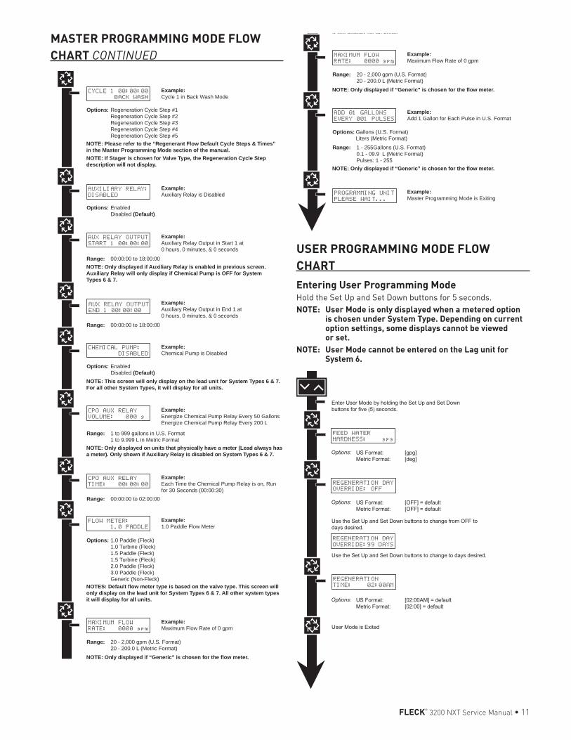
Trip Points 1, 2, and 3 (System 14 only)This program step selects up to three Trip Points programmed on the master timer only (Valve Address #1).The actual required number of Trip Points in a system is one less than the number of valves in the system.Trip Point 1 represents the system flow rate at which a second valve will be brought In Service or Standby.Trip Point 2 represents the system flow rate at which a third valve will be brought In Service or Standby. Trip Point 3 represents the system flow rate at which a fourth valve will be brought In Service or Standby.
Trip Point 1 Trip Point 2 Trip Point 3
Range: 1 – 997 GPM
U.S.: Value of Trip Point 1 plus 1 to 998
U.S.: Trip Point 2 plus 1 to 999
Range: 0.01 – 9.97
M3/M
Metric: Value of Trip Point 1 plus .01 to
9.98
Metric: Trip Point 2 plus 0.01 to 9.99
Trip Delays 1, 2, and 3 (System 14 only)This program step selects each Trip Delay time that is addressed with each Trip Point and will be programmed on the Master timer only (Valve Address #1). The Trip Delay time represents a minimum amount of time the system flow rate is required to be equal or greater than the Trip Points to bring a unit In Service. It also is the minimum amount of time the system flow rate is required to be less than the Trip Points to remove a unit from In Service to Standby.
Trip Delay 1 Trip Delay 2 Trip Delay 3
Default: 30 SecondsRange:
30 - 99 SecondsRange:
30 - 99 SecondsRange:
30 - 99 Seconds
Regeneration Cycle StepsThis step programs the Regeneration Cycle step times 1 through 5. Please Refer to the chart below for regenerant flow default cycle steps and times.
Regenerant Flow Cycle 1 Time Cycle 2 Time
Downflow Backwash 10 Minutes
Brine & Slow Rinse 1 Hour
UF Brine Draw Brine & Slow Rinse 1 Hour Backwash 10
Minutes
UF Fill First Brine Tank Fill
12 Minutes
Brine Making 1 Hour
Regenerant Flow Cycle 3 Time Cycle 4 Time
Downflow Rapid Rinse 10 Minutes
Brine Tank Fill
12 Minutes
UF Brine Draw Rapid Rinse 10 Minutes
Brine Tank Fill
12 Minutes
UF Fill First Brine & Slow Rinse 1 Hour Backwash 10
Minutes
Regenerant Flow Cycle 5 Time
Downflow Pause N/A
UF Brine Draw Pause N/A
UF Fill First Rapid Rinse 10 Minutes
VALVE ADDRESS:
#2
Options: Valve Address #1 (First Control Valve) Valve Address #2 (Second Control Valve) (Default) Valve Address #3 (Third Control Valve) Valve Address #4 (Fourth Control Valve)
SYSTEM TYPE: 4
SINGLE UNIT
Options: System 4 (single unit) System 5 (2-4 units) Parallel Interlock System 6 (2-4 units) Parallel Series Regeneration System 7 (2 units) Alternating System 9 (2-4 units) Alternating System 14 (2-4 units) Demand Recall
Example:System Type 4, Single Unit
Example:Valve Address #2 (Second Control Valve) (Default)
Example:U.S. Gallons (Default)
SELECT LANGUAGE:
ENGLISH
Options: English Espanol Portugues Deutsch Francais
Example:English
VALVE TYPE:
2750
Options: 2750 (Default) 2850 2900 3150 3900 Stager - Notch Cam
Example:2750 (Default)
REGEN TYPE:
TIME CLK DELAYED
Options: Time Clock Delayed (System 4 Only) (Default) Meter Immediate (All System Types) Meter Delayed Fixed Reserve (Systems 4 & 6 Only)
Example:Time Clock Delayed (Default)
REGENERANT FLOW:
DOWNFLOW
Options: Downflow (Default) Up Flow UF Fill First
Example:Downflow (Default)
REMOTE SIGNAL
START: 00:06:00
Options: 00:06:00 (Default)Range: 1 second to 99 minutes (1 hour, 39 minutes)NOTE: This display will not be viewed in System 4
Example:00:06:00 (Default)(Hours:Minutes:Seconds)
NOTE: This screen will not display for System Type 4.
SYSTEM SIZE:
2 VALVES
Options: 2 Valves in the System (Default) 3 Valves in the System 4 Valves in the System
Example:2 Valves in the System (Default)
Range: 2 to 4 Valves in the SystemNOTE: This screen will not display for System Type 4.
DISPLAY FORMAT:
US-GALLONS
Options: U.S. - Gallons (Default) Eu Metric - Liters (Metric)
NOTE: In European Units - Liters (Metric) mode, the display will be in 24-hour time.
NOTE: In U.S. - Gallons mode, the display will be in 12-hour time.
UNIT CAPACITY:
00000000 GRAINS
Options: Grains (in U.S. Format) (Default) Grams (in Metric Format)
Example:Grains (Default)
NOTE: Use the Shift button to move to the left.
Range: 1 to 9,900,000 Grain Capacity in U.S. Format 1 to 198,000 grams CaCO3 Capacity in Metric Format
Example:00% (Default)
CAPACITY SAFETY
FACTOR: 00%
Range: 0 to 50%NOTE: Use the Shift button to move to the left.
FEED WATER
HARDNESS: 15 GPG
Range: 1 to 199 Grains/Gallon (U.S. Format) 20 to 1,999 miligrams CaCO3/L (Metric Format)
Example:15 GPG (U.S. Format) (Default)
NOTE: Use the Shift button to move to the left.NOTE: This screen will only display on the lead unit for System Types 6 & 7.For all other System Types, it will display for all units.
TRIP POINT 1:
000 gpm
NOTE: Display will not appear unless timer is programmed as valve position #1. Use the Shift button to change each decimal position.
REGENERATION DAY
OVERRIDE:OFF
Example:Off (Default)On (Default for time clock)
REGENERATION DAY
OVERRIDE:01 DAYS
Options: Off (Default for meter) or On
Example:1 Day
Range: 1 to 99 Days
REGENERATION
TIME: 02:00AM
Example:2:00 A.M. (Default)
Options: A.M. (U.S. Format) HR (Metric Format)NOTE: Regeneration time will not appear unless Regeneration Day Override is on.
CYCLE 1 00:00:00
BACK WASH
Example:Cycle 1 in Back Wash Mode
Options: Regeneration Cycle Step #1 Regeneration Cycle Step #2 Regeneration Cycle Step #3 Regeneration Cycle Step #4 Regeneration Cycle Step #5NOTE: Please refer to the “Regenerant Flow Default Cycle Steps & Times” in the Master Programming Mode section of the manual.NOTE: If Stager is chosen for Valve Type, the Regeneration Cycle Step description will not display.
AUXILIARY RELAY:
DISABLED
Example:Auxiliary Relay is Disabled
Options: Enabled Disabled (Default)
AUX RELAY OUTPUT
START 1 00:00:00
Example:Auxiliary Relay Output in Start 1 at 0 hours, 0 minutes, & 0 seconds
Range: 00:00:00 to 18:00:00NOTE: Only displayed if Auxiliary Relay is enabled in previous screen. Auxiliary Relay will only display if Chemical Pump is OFF for System Types 6 & 7.
AUX RELAY OUTPUT
END 1 00:00:00
Example:Auxiliary Relay Output in End 1 at 0 hours, 0 minutes, & 0 seconds
Range: 00:00:00 to 18:00:00
CHEMICAL PUMP:
DISABLED
Example:Chemical Pump is Disabled
Options: Enabled Disabled (Default)NOTE: This screen will only display on the lead unit for System Types 6 & 7. For all other System Types, it will display for all units.
CPO AUX RELAY
VOLUME: 000 g
Example:Energize Chemical Pump Relay Every 50 GallonsEnergize Chemical Pump Relay Every 200 L
Range: 1 to 999 gallons in U.S. Format 1 to 9.999 L in Metric FormatNOTE: Only displayed on units that physically have a meter (Lead always has a meter). Only shown if Auxiliary Relay is disabled on System Types 6 & 7.
CPO AUX RELAY
TIME: 00:00:00
Example:Each Time the Chemical Pump Relay is on, Run for 30 Seconds (00:00:30)
Range: 00:00:00 to 02:00:00
FLOW METER:
1.0 PADDLE
Example:1.0 Paddle Flow Meter
Options: 1.0 Paddle (Fleck) 1.0 Turbine (Fleck) 1.5 Paddle (Fleck) 1.5 Turbine (Fleck) 2.0 Paddle (Fleck) 3.0 Paddle (Fleck) Generic (Non-Fleck)NOTES: Default flow meter type is based on the valve type. This screen will only display on the lead unit for System Types 6 & 7. All other system types it will display for all units.
MAXIMUM FLOW
RATE: 0000 gpm
Example:Maximum Flow Rate of 0 gpm
Range: 20 - 2,000 gpm (U.S. Format) 20 - 200.0 L (Metric Format) NOTE: Only displayed if “Generic” is chosen for the flow meter.
Range: 1 - 255Gallons (U.S. Format) 0.1 - 09.9 L (Metric Format) Pulses: 1 - 255
Options: Gallons (U.S. Format) Liters (Metric Format)
ADD 01 GALLONS
EVERY 001 PULSES
Example:Add 1 Gallon for Each Pulse in U.S. Format
NOTE: Only displayed if “Generic” is chosen for the flow meter.
PROGRAMMING UNIT
PLEASE WAIT...
Example:Master Programming Mode is Exiting
NOTE: Display will not appear unless timer is programmed as valve position #1. Use the Shift button to move one space to the left.
TRIP DELAY 1:
30 SECONDS
NOTE: Display will not appear unless timer is programmed as valve position #1. System size must be 3 or 4 to appear. Use the Shift button to move one space to the left.
TRIP DELAY 2:
30 SECONDS
NOTE: Display will not appear unless timer is programmed as valve position #1. System size must be 3 or 4 to appear. Use the Shift button to move one space to the left.
TRIP POINT 2:
gpm
NOTE: Display will not appear unless timer is programmed as valve position #1. System size must be 4 to appear. Use the Shift button to move one space to the left.
TRIP POINT 3:
gpm
NOTE: Display will not appear unless timer is programmed as valve position #1. System size must be 4 to appear. Use the Shift button to move one space to the left.
TRIP DELAY 3:
30 SECONDS
MASTER PROGRAMMING MODE FLOW CHART CONTINUED
VALVE ADDRESS:
#2
Options: Valve Address #1 (First Control Valve) Valve Address #2 (Second Control Valve) (Default) Valve Address #3 (Third Control Valve) Valve Address #4 (Fourth Control Valve)
SYSTEM TYPE: 4
SINGLE UNIT
Options: System 4 (single unit) System 5 (2-4 units) Parallel Interlock System 6 (2-4 units) Parallel Series Regeneration System 7 (2 units) Alternating System 9 (2-4 units) Alternating System 14 (2-4 units) Demand Recall
Example:System Type 4, Single Unit
Example:Valve Address #2 (Second Control Valve) (Default)
Example:U.S. Gallons (Default)
SELECT LANGUAGE:
ENGLISH
Options: English Espanol Portugues Deutsch Francais
Example:English
VALVE TYPE:
2750
Options: 2750 (Default) 2850 2900 3150 3900 Stager - Notch Cam
Example:2750 (Default)
REGEN TYPE:
TIME CLK DELAYED
Options: Time Clock Delayed (System 4 Only) (Default) Meter Immediate (All System Types) Meter Delayed Fixed Reserve (Systems 4 & 6 Only)
Example:Time Clock Delayed (Default)
REGENERANT FLOW:
DOWNFLOW
Options: Downflow (Default) Up Flow UF Fill First
Example:Downflow (Default)
REMOTE SIGNAL
START: 00:06:00
Options: 00:06:00 (Default)Range: 1 second to 99 minutes (1 hour, 39 minutes)NOTE: This display will not be viewed in System 4
Example:00:06:00 (Default)(Hours:Minutes:Seconds)
NOTE: This screen will not display for System Type 4.
SYSTEM SIZE:
2 VALVES
Options: 2 Valves in the System (Default) 3 Valves in the System 4 Valves in the System
Example:2 Valves in the System (Default)
Range: 2 to 4 Valves in the SystemNOTE: This screen will not display for System Type 4.
DISPLAY FORMAT:
US-GALLONS
Options: U.S. - Gallons (Default) Eu Metric - Liters (Metric)
NOTE: In European Units - Liters (Metric) mode, the display will be in 24-hour time.
NOTE: In U.S. - Gallons mode, the display will be in 12-hour time.
UNIT CAPACITY:
00000000 GRAINS
Options: Grains (in U.S. Format) (Default) Grams (in Metric Format)
Example:Grains (Default)
NOTE: Use the Shift button to move to the left.
Range: 1 to 9,900,000 Grain Capacity in U.S. Format 1 to 198,000 grams CaCO3 Capacity in Metric Format
Example:00% (Default)
CAPACITY SAFETY
FACTOR: 00%
Range: 0 to 50%NOTE: Use the Shift button to move to the left.
FEED WATER
HARDNESS: 15 GPG
Range: 1 to 199 Grains/Gallon (U.S. Format) 20 to 1,999 miligrams CaCO3/L (Metric Format)
Example:15 GPG (U.S. Format) (Default)
NOTE: Use the Shift button to move to the left.NOTE: This screen will only display on the lead unit for System Types 6 & 7.For all other System Types, it will display for all units.
TRIP POINT 1:
000 gpm
NOTE: Display will not appear unless timer is programmed as valve position #1. Use the Shift button to change each decimal position.
REGENERATION DAY
OVERRIDE:OFF
Example:Off (Default)On (Default for time clock)
REGENERATION DAY
OVERRIDE:01 DAYS
Options: Off (Default for meter) or On
Example:1 Day
Range: 1 to 99 Days
REGENERATION
TIME: 02:00AM
Example:2:00 A.M. (Default)
Options: A.M. (U.S. Format) HR (Metric Format)NOTE: Regeneration time will not appear unless Regeneration Day Override is on.
CYCLE 1 00:00:00
BACK WASH
Example:Cycle 1 in Back Wash Mode
Options: Regeneration Cycle Step #1 Regeneration Cycle Step #2 Regeneration Cycle Step #3 Regeneration Cycle Step #4 Regeneration Cycle Step #5NOTE: Please refer to the “Regenerant Flow Default Cycle Steps & Times” in the Master Programming Mode section of the manual.NOTE: If Stager is chosen for Valve Type, the Regeneration Cycle Step description will not display.
AUXILIARY RELAY:
DISABLED
Example:Auxiliary Relay is Disabled
Options: Enabled Disabled (Default)
AUX RELAY OUTPUT
START 1 00:00:00
Example:Auxiliary Relay Output in Start 1 at 0 hours, 0 minutes, & 0 seconds
Range: 00:00:00 to 18:00:00NOTE: Only displayed if Auxiliary Relay is enabled in previous screen. Auxiliary Relay will only display if Chemical Pump is OFF for System Types 6 & 7.
AUX RELAY OUTPUT
END 1 00:00:00
Example:Auxiliary Relay Output in End 1 at 0 hours, 0 minutes, & 0 seconds
Range: 00:00:00 to 18:00:00
CHEMICAL PUMP:
DISABLED
Example:Chemical Pump is Disabled
Options: Enabled Disabled (Default)NOTE: This screen will only display on the lead unit for System Types 6 & 7. For all other System Types, it will display for all units.
CPO AUX RELAY
VOLUME: 000 g
Example:Energize Chemical Pump Relay Every 50 GallonsEnergize Chemical Pump Relay Every 200 L
Range: 1 to 999 gallons in U.S. Format 1 to 9.999 L in Metric FormatNOTE: Only displayed on units that physically have a meter (Lead always has a meter). Only shown if Auxiliary Relay is disabled on System Types 6 & 7.
CPO AUX RELAY
TIME: 00:00:00
Example:Each Time the Chemical Pump Relay is on, Run for 30 Seconds (00:00:30)
Range: 00:00:00 to 02:00:00
FLOW METER:
1.0 PADDLE
Example:1.0 Paddle Flow Meter
Options: 1.0 Paddle (Fleck) 1.0 Turbine (Fleck) 1.5 Paddle (Fleck) 1.5 Turbine (Fleck) 2.0 Paddle (Fleck) 3.0 Paddle (Fleck) Generic (Non-Fleck)NOTES: Default flow meter type is based on the valve type. This screen will only display on the lead unit for System Types 6 & 7. All other system types it will display for all units.
MAXIMUM FLOW
RATE: 0000 gpm
Example:Maximum Flow Rate of 0 gpm
Range: 20 - 2,000 gpm (U.S. Format) 20 - 200.0 L (Metric Format) NOTE: Only displayed if “Generic” is chosen for the flow meter.
Range: 1 - 255Gallons (U.S. Format) 0.1 - 09.9 L (Metric Format) Pulses: 1 - 255
Options: Gallons (U.S. Format) Liters (Metric Format)
ADD 01 GALLONS
EVERY 001 PULSES
Example:Add 1 Gallon for Each Pulse in U.S. Format
NOTE: Only displayed if “Generic” is chosen for the flow meter.
PROGRAMMING UNIT
PLEASE WAIT...
Example:Master Programming Mode is Exiting
NOTE: Display will not appear unless timer is programmed as valve position #1. Use the Shift button to move one space to the left.
TRIP DELAY 1:
30 SECONDS
NOTE: Display will not appear unless timer is programmed as valve position #1. System size must be 3 or 4 to appear. Use the Shift button to move one space to the left.
TRIP DELAY 2:
30 SECONDS
NOTE: Display will not appear unless timer is programmed as valve position #1. System size must be 3 or 4 to appear. Use the Shift button to move one space to the left.
TRIP POINT 2:
gpm
NOTE: Display will not appear unless timer is programmed as valve position #1. System size must be 4 to appear. Use the Shift button to move one space to the left.
TRIP POINT 3:
gpm
NOTE: Display will not appear unless timer is programmed as valve position #1. System size must be 4 to appear. Use the Shift button to move one space to the left.
TRIP DELAY 3:
30 SECONDS
FLECK® 3200 NXT Service Manual • 11
USER PROGRAMMING MODE FLOW CHARTEntering User Programming ModeHold the Set Up and Set Down buttons for 5 seconds.NOTE: User Mode is only displayed when a metered option
is chosen under System Type. Depending on current option settings, some displays cannot be viewed or set.
NOTE: User Mode cannot be entered on the Lag unit for System 6.
FEED WATER
HARDNESS: gpg
REGENERATION DAY
OVERRIDE: OFF
REGENERATION DAY
OVERRIDE:99 DAYS
REGENERATION
TIME: 02:00AM
MASTER PROGRAMMING MODE FLOW CHART CONTINUED
VALVE ADDRESS:
#2
Options: Valve Address #1 (First Control Valve) Valve Address #2 (Second Control Valve) (Default) Valve Address #3 (Third Control Valve) Valve Address #4 (Fourth Control Valve)
SYSTEM TYPE: 4
SINGLE UNIT
Options: System 4 (single unit) System 5 (2-4 units) Parallel Interlock System 6 (2-4 units) Parallel Series Regeneration System 7 (2 units) Alternating System 9 (2-4 units) Alternating System 14 (2-4 units) Demand Recall
Example:System Type 4, Single Unit
Example:Valve Address #2 (Second Control Valve) (Default)
Example:U.S. Gallons (Default)
SELECT LANGUAGE:
ENGLISH
Options: English Espanol Portugues Deutsch Francais
Example:English
VALVE TYPE:
2750
Options: 2750 (Default) 2850 2900 3150 3900 Stager - Notch Cam
Example:2750 (Default)
REGEN TYPE:
TIME CLK DELAYED
Options: Time Clock Delayed (System 4 Only) (Default) Meter Immediate (All System Types) Meter Delayed Fixed Reserve (Systems 4 & 6 Only)
Example:Time Clock Delayed (Default)
REGENERANT FLOW:
DOWNFLOW
Options: Downflow (Default) Up Flow UF Fill First
Example:Downflow (Default)
REMOTE SIGNAL
START: 00:06:00
Options: 00:06:00 (Default)Range: 1 second to 99 minutes (1 hour, 39 minutes)NOTE: This display will not be viewed in System 4
Example:00:06:00 (Default)(Hours:Minutes:Seconds)
NOTE: This screen will not display for System Type 4.
SYSTEM SIZE:
2 VALVES
Options: 2 Valves in the System (Default) 3 Valves in the System 4 Valves in the System
Example:2 Valves in the System (Default)
Range: 2 to 4 Valves in the SystemNOTE: This screen will not display for System Type 4.
DISPLAY FORMAT:
US-GALLONS
Options: U.S. - Gallons (Default) Eu Metric - Liters (Metric)
NOTE: In European Units - Liters (Metric) mode, the display will be in 24-hour time.
NOTE: In U.S. - Gallons mode, the display will be in 12-hour time.
UNIT CAPACITY:
00000000 GRAINS
Options: Grains (in U.S. Format) (Default) Grams (in Metric Format)
Example:Grains (Default)
NOTE: Use the Shift button to move to the left.
Range: 1 to 9,900,000 Grain Capacity in U.S. Format 1 to 198,000 grams CaCO3 Capacity in Metric Format
Example:00% (Default)
CAPACITY SAFETY
FACTOR: 00%
Range: 0 to 50%NOTE: Use the Shift button to move to the left.
FEED WATER
HARDNESS: 15 GPG
Range: 1 to 199 Grains/Gallon (U.S. Format) 20 to 1,999 miligrams CaCO3/L (Metric Format)
Example:15 GPG (U.S. Format) (Default)
NOTE: Use the Shift button to move to the left.NOTE: This screen will only display on the lead unit for System Types 6 & 7.For all other System Types, it will display for all units.
TRIP POINT 1:
000 gpm
NOTE: Display will not appear unless timer is programmed as valve position #1. Use the Shift button to change each decimal position.
REGENERATION DAY
OVERRIDE:OFF
Example:Off (Default)On (Default for time clock)
REGENERATION DAY
OVERRIDE:01 DAYS
Options: Off (Default for meter) or On
Example:1 Day
Range: 1 to 99 Days
REGENERATION
TIME: 02:00AM
Example:2:00 A.M. (Default)
Options: A.M. (U.S. Format) HR (Metric Format)NOTE: Regeneration time will not appear unless Regeneration Day Override is on.
CYCLE 1 00:00:00
BACK WASH
Example:Cycle 1 in Back Wash Mode
Options: Regeneration Cycle Step #1 Regeneration Cycle Step #2 Regeneration Cycle Step #3 Regeneration Cycle Step #4 Regeneration Cycle Step #5NOTE: Please refer to the “Regenerant Flow Default Cycle Steps & Times” in the Master Programming Mode section of the manual.NOTE: If Stager is chosen for Valve Type, the Regeneration Cycle Step description will not display.
AUXILIARY RELAY:
DISABLED
Example:Auxiliary Relay is Disabled
Options: Enabled Disabled (Default)
AUX RELAY OUTPUT
START 1 00:00:00
Example:Auxiliary Relay Output in Start 1 at 0 hours, 0 minutes, & 0 seconds
Range: 00:00:00 to 18:00:00NOTE: Only displayed if Auxiliary Relay is enabled in previous screen. Auxiliary Relay will only display if Chemical Pump is OFF for System Types 6 & 7.
AUX RELAY OUTPUT
END 1 00:00:00
Example:Auxiliary Relay Output in End 1 at 0 hours, 0 minutes, & 0 seconds
Range: 00:00:00 to 18:00:00
CHEMICAL PUMP:
DISABLED
Example:Chemical Pump is Disabled
Options: Enabled Disabled (Default)NOTE: This screen will only display on the lead unit for System Types 6 & 7. For all other System Types, it will display for all units.
CPO AUX RELAY
VOLUME: 000 g
Example:Energize Chemical Pump Relay Every 50 GallonsEnergize Chemical Pump Relay Every 200 L
Range: 1 to 999 gallons in U.S. Format 1 to 9.999 L in Metric FormatNOTE: Only displayed on units that physically have a meter (Lead always has a meter). Only shown if Auxiliary Relay is disabled on System Types 6 & 7.
CPO AUX RELAY
TIME: 00:00:00
Example:Each Time the Chemical Pump Relay is on, Run for 30 Seconds (00:00:30)
Range: 00:00:00 to 02:00:00
FLOW METER:
1.0 PADDLE
Example:1.0 Paddle Flow Meter
Options: 1.0 Paddle (Fleck) 1.0 Turbine (Fleck) 1.5 Paddle (Fleck) 1.5 Turbine (Fleck) 2.0 Paddle (Fleck) 3.0 Paddle (Fleck) Generic (Non-Fleck)NOTES: Default flow meter type is based on the valve type. This screen will only display on the lead unit for System Types 6 & 7. All other system types it will display for all units.
MAXIMUM FLOW
RATE: 0000 gpm
Example:Maximum Flow Rate of 0 gpm
Range: 20 - 2,000 gpm (U.S. Format) 20 - 200.0 L (Metric Format) NOTE: Only displayed if “Generic” is chosen for the flow meter.
Range: 1 - 255Gallons (U.S. Format) 0.1 - 09.9 L (Metric Format) Pulses: 1 - 255
Options: Gallons (U.S. Format) Liters (Metric Format)
ADD 01 GALLONS
EVERY 001 PULSES
Example:Add 1 Gallon for Each Pulse in U.S. Format
NOTE: Only displayed if “Generic” is chosen for the flow meter.
PROGRAMMING UNIT
PLEASE WAIT...
Example:Master Programming Mode is Exiting
NOTE: Display will not appear unless timer is programmed as valve position #1. Use the Shift button to move one space to the left.
TRIP DELAY 1:
30 SECONDS
NOTE: Display will not appear unless timer is programmed as valve position #1. System size must be 3 or 4 to appear. Use the Shift button to move one space to the left.
TRIP DELAY 2:
30 SECONDS
NOTE: Display will not appear unless timer is programmed as valve position #1. System size must be 3 or 4 to appear. Use the Shift button to move one space to the left.
TRIP POINT 2:
gpm
NOTE: Display will not appear unless timer is programmed as valve position #1. System size must be 4 to appear. Use the Shift button to move one space to the left.
TRIP POINT 3:
gpm
NOTE: Display will not appear unless timer is programmed as valve position #1. System size must be 4 to appear. Use the Shift button to move one space to the left.
TRIP DELAY 3:
30 SECONDS
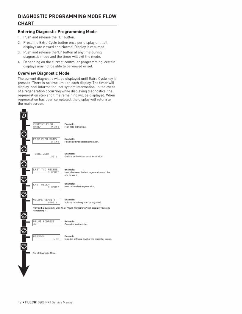
12 • FLECK® 3200 NXT Service Manual
DIAGNOSTIC PROGRAMMING MODE FLOW CHARTEntering Diagnostic Programming Mode1. Push and release the "D" button.2. Press the Extra Cycle button once per display until all
displays are viewed and Normal Display is resumed.3. Push and release the"D" button at anytime during
diagnostic mode and the timer will exit the mode.4. Depending on the current controller programming, certain
displays may not be able to be viewed or set.
Overview Diagnostic ModeThe current diagnostic will be displayed until Extra Cycle key is pressed. There is no time limit on each display. The timer will display local information, not system information. In the event of a regeneration occurring while displaying diagnostics, the regeneration step and time remaining will be displayed. When regeneration has been completed, the display will return to the main screen.
CURRENT FLOW
RATE: 0 gpm
PEAK FLOW RATE:
0 gpm
TOTALIZER:
130 g
LAST TWO REGENS:
0 HOURS
LAST REGEN
0 HOURS
VOLUME REMAIN:
1000 g
VALVE ADDRESS
#2
VERSION:
X.XX
NOTE: If a System 6, Unit #1 of “Tank Remaining” will display “System Remaining”.
Example:Flow rate at this time.
Example:Peak flow since last regeneration.
Example:Gallons at the outlet since installation.
Example:Hours between the last regeneration and the one before it.
Example:Hours since last regeneration.
Example:Volume remaining (can be adjusted).
Example:Controller unit number.
Example:Installed software level of the controller in use.
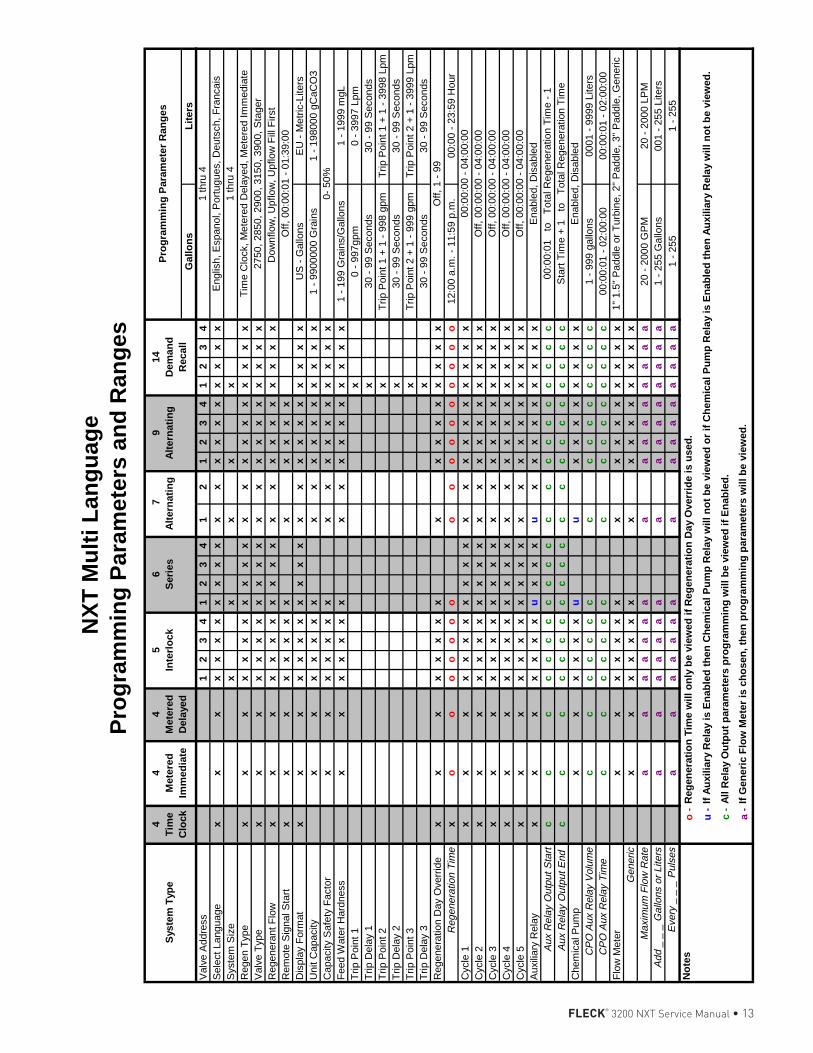
FLECK® 3200 NXT Service Manual • 13
NX
T M
ult
i Lan
gu
age
P
rog
ram
min
g P
aram
eter
s an
d R
ang
es
Gal
lon
s L
iter
sV
alve
Add
ress
12
34
12
34
12
12
34
12
34
Sel
ect L
angu
age
xx
xx
xx
xx
xx
xx
xx
xx
xx
xx
xS
yste
m S
ize
xx
xx
xR
egen
Typ
ex
xx
xx
xx
xx
xx
xx
xx
xx
xx
xx
Val
ve T
ype
xx
xx
xx
xx
xx
xx
xx
xx
xx
xx
xR
egen
eran
t Flo
wx
xx
xx
xx
xx
xx
xx
xx
xx
xx
xx
Rem
ote
Sig
nal S
tart
xx
xx
xx
xx
xx
xx
xD
ispl
ay F
orm
atx
xx
xx
xx
xx
xx
xx
xx
xx
xx
xx
US
- G
allo
nsE
U -
Met
ric-L
iters
Uni
t Cap
acity
xx
xx
xx
xx
xx
xx
xx
xx
x1
- 99
0000
0 G
rain
s1
- 19
8000
gC
aCO
3C
apac
ity S
afet
y F
acto
rx
xx
xx
xx
xx
xx
xx
xx
xx
Fee
d W
ater
Har
dnes
sx
xx
xx
xx
xx
xx
xx
xx
xx
1 -
199
Gra
ins/
Gal
lons
1 -
1999
mgL
Trip
Poi
nt 1
x0
- 99
7gpm
0 -
3997
Lpm
Trip
Del
ay 1
x30
- 9
9 S
econ
ds30
- 9
9 S
econ
dsT
rip P
oint
2x
Trip
Poi
nt 1
+ 1
- 9
98 g
pmT
rip P
oint
1 +
1 -
399
8 Lp
mT
rip D
elay
2x
30 -
99
Sec
onds
30 -
99
Sec
onds
Trip
Poi
nt 3
xT
rip P
oint
2 +
1 -
999
gpm
Trip
Poi
nt 2
+ 1
- 3
999
Lpm
Trip
Del
ay 3
x30
- 9
9 S
econ
ds30
- 9
9 S
econ
dsR
egen
erat
ion
Day
Ove
rrid
ex
xx
xx
xx
xx
x
xx
xx
xx
xR
egen
erat
ion
Tim
ex
oo
oo
oo
oo
oo
oo
oo
oo
o12
:00
a.m
. - 1
1:59
p.m
.00
:00
- 23
:59
Hou
rC
ycle
1
xx
xx
xx
xx
xx
xx
xx
xx
xx
xx
xC
ycle
2x
xx
xx
xx
xx
xx
xx
xx
xx
xx
xx
Cyc
le 3
xx
xx
xx
xx
xx
xx
xx
xx
xx
xx
xC
ycle
4x
xx
xx
xx
xx
xx
xx
xx
xx
xx
xx
Cyc
le 5
xx
xx
xx
xx
xx
xx
xx
xx
xx
xx
xA
uxili
ary
Rel
ayx
xx
xx
xx
ux
xx
ux
xx
xx
xx
xx
Aux
Rel
ay O
utpu
t Sta
rtc
cc
cc
cc
cc
cc
cc
cc
cc
cc
cc
Aux
Rel
ay O
utpu
t End
c
cc
cc
cc
cc
cc
cc
cc
cc
cc
cc
Che
mic
al P
ump
xx
xx
xx
uu
xx
xx
xx
xx
CP
O A
ux R
elay
Vol
ume
cc
cc
cc
cc
cc
cc
cc
cc
1 -
999
gallo
ns00
01 -
999
9 Li
ters
CP
O A
ux R
elay
Tim
e
cc
cc
cc
cc
cc
cc
cc
cc
00:0
0:01
- 0
2:00
:00
00:0
0:01
- 0
2:00
:00
Flo
w M
eter
xx
xx
xx
xx
xx
xx
xx
xx
Gen
eric
xx
xx
xx
xx
xx
xx
xx
xx
Max
imum
Flo
w R
ate
aa
aa
aa
aa
aa
aa
aa
aa
20 -
200
0 G
PM
20 -
200
0 LP
MA
dd _
_ _
Gal
lons
or
Lite
rsa
aa
aa
aa
aa
aa
aa
aa
a1
- 25
5 G
allo
ns00
1 -
255
Lite
rsE
very
_ _
_ P
ulse
sa
aa
aa
aa
aa
aa
aa
aa
a1
- 25
51
- 25
5N
ote
so
-
u - c -
a -
Sys
tem
Typ
e
If G
ener
ic F
low
Met
er is
ch
ose
n, t
hen
pro
gra
mm
ing
par
amet
ers
will
be
view
ed.
Reg
ener
atio
n T
ime
will
on
ly b
e vi
ewed
if R
egen
erat
ion
Day
Ove
rrid
e is
use
d.
If A
uxi
liary
Rel
ay is
En
able
d t
hen
Ch
emic
al P
um
p R
elay
will
no
t b
e vi
ewed
or
if C
hem
ical
Pu
mp
Rel
ay is
En
able
d t
hen
Au
xilia
ry R
elay
will
no
t b
e vi
ewed
.
All
Rel
ay O
utp
ut
par
amet
ers
pro
gra
mm
ing
will
be
view
ed if
En
able
d.
00:0
0:01
to
T
otal
Reg
ener
atio
n T
ime
- 1
Sta
rt T
ime
+ 1
to
T
otal
Reg
ener
atio
n T
ime
Ena
bled
, Dis
able
d
Off,
1 -
99
00:
00:0
0 -
04:0
0:00
Off,
00:
00:0
0 -
04:0
0:00
1" 1
.5"
Pad
dle
or T
urbi
ne, 2
" P
addl
e, 3
" P
addl
e, G
ener
ic
Off,
00:
00:0
0 -
04:0
0:00
Off,
00:
00:0
0 -
04:0
0:00
Off,
00:
00:0
0 -
04:0
0:00
Ena
bled
, Dis
able
d
2750
, 285
0, 2
900,
315
0, 3
900,
Sta
ger
Dow
nflo
w, U
pflo
w, U
pflo
w F
ill F
irst
Off,
00:
00:0
1 -
01:3
9:00
0- 5
0%
6
S
erie
s7
A
lter
nat
ing
9
A
lter
nat
ing
Tim
e C
lock
, Met
ered
Del
ayed
, Met
ered
Imm
edia
te
Pro
gra
mm
ing
Par
amet
er R
ang
es4
Tim
e C
lock
4
Met
ered
Im
med
iate
4
Met
ered
D
elay
ed
5
In
terl
ock
14
D
eman
d
Rec
all
1 th
ru 4
Eng
lish,
Esp
anol
, Por
tugu
es, D
euts
ch, F
ranc
ais
1 th
ru 4
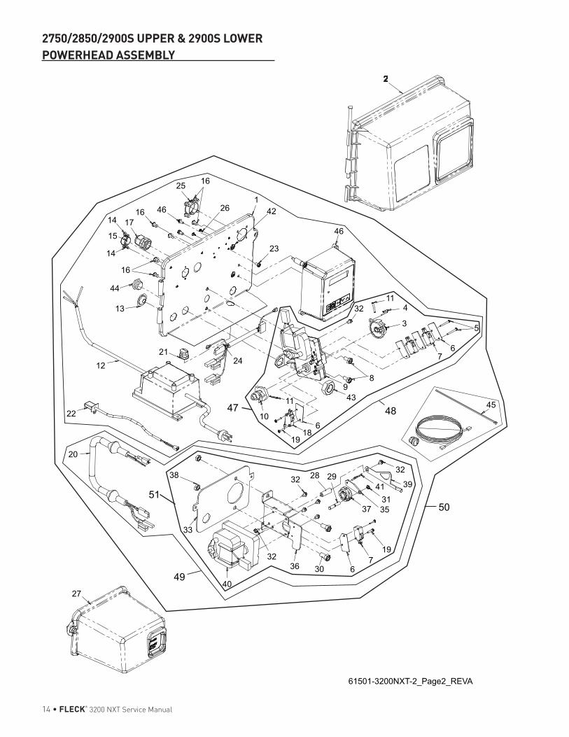
14 • FLECK® 3200 NXT Service Manual
2750/2850/2900S UPPER & 2900S LOWER POWERHEAD ASSEMBLY
37 3531
41 39
32
197
6303632
40
20
38
33
22
1221
13
44
16
14
15
14 1716 46
25 16
261
42
23
46
2
114
3 5
67
10
19
32 28 29
186
11 439
8
32
24
61501-3200NXT-2_Page2_REVA
27
4547 48
51
49
50
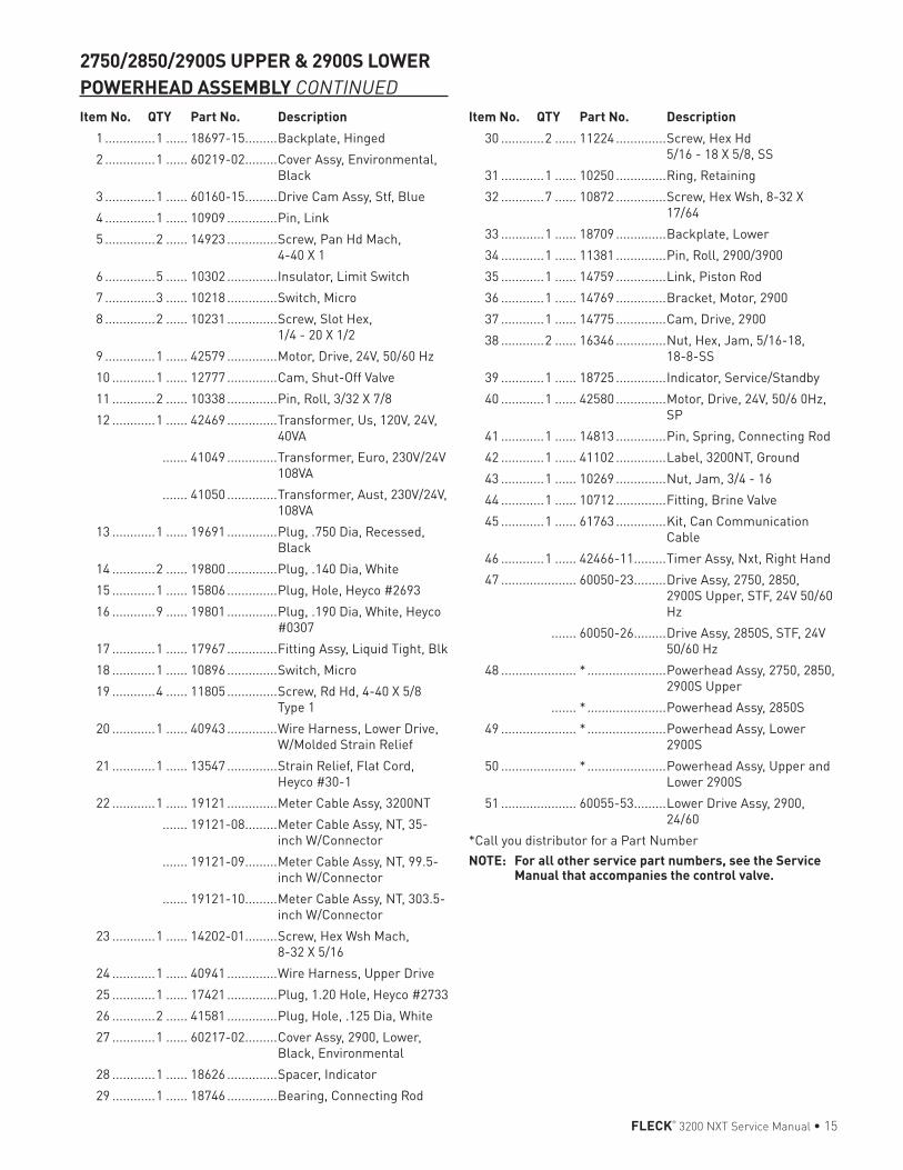
FLECK® 3200 NXT Service Manual • 15
Item No. QTY Part No. Description 1 ..............1 ...... 18697-15 .........Backplate, Hinged 2 ..............1 ...... 60219-02 .........Cover Assy, Environmental,
Black 3 ..............1 ...... 60160-15 .........Drive Cam Assy, Stf, Blue 4 ..............1 ...... 10909 ..............Pin, Link 5 ..............2 ...... 14923 ..............Screw, Pan Hd Mach,
4-40 X 1 6 ..............5 ...... 10302 ..............Insulator, Limit Switch 7 ..............3 ...... 10218 ..............Switch, Micro 8 ..............2 ...... 10231 ..............Screw, Slot Hex,
1/4 - 20 X 1/2 9 ..............1 ...... 42579 ..............Motor, Drive, 24V, 50/60 Hz 10 ............1 ...... 12777 ..............Cam, Shut-Off Valve 11 ............2 ...... 10338 ..............Pin, Roll, 3/32 X 7/8 12 ............1 ...... 42469 ..............Transformer, Us, 120V, 24V,
40VA ....... 41049 ..............Transformer, Euro, 230V/24V
108VA ....... 41050 ..............Transformer, Aust, 230V/24V,
108VA 13 ............1 ...... 19691 ..............Plug, .750 Dia, Recessed,
Black 14 ............2 ...... 19800 ..............Plug, .140 Dia, White 15 ............1 ...... 15806 ..............Plug, Hole, Heyco #2693 16 ............9 ...... 19801 ..............Plug, .190 Dia, White, Heyco
#0307 17 ............1 ...... 17967 ..............Fitting Assy, Liquid Tight, Blk 18 ............1 ...... 10896 ..............Switch, Micro 19 ............4 ...... 11805 ..............Screw, Rd Hd, 4-40 X 5/8
Type 1 20 ............1 ...... 40943 ..............Wire Harness, Lower Drive,
W/Molded Strain Relief 21 ............1 ...... 13547 ..............Strain Relief, Flat Cord,
Heyco #30-1 22 ............1 ...... 19121 ..............Meter Cable Assy, 3200NT ....... 19121-08 .........Meter Cable Assy, NT, 35-
inch W/Connector ....... 19121-09 .........Meter Cable Assy, NT, 99.5-
inch W/Connector ....... 19121-10 .........Meter Cable Assy, NT, 303.5-
inch W/Connector 23 ............1 ...... 14202-01 .........Screw, Hex Wsh Mach,
8-32 X 5/16 24 ............1 ...... 40941 ..............Wire Harness, Upper Drive 25 ............1 ...... 17421 ..............Plug, 1.20 Hole, Heyco #2733 26 ............2 ...... 41581 ..............Plug, Hole, .125 Dia, White 27 ............1 ...... 60217-02 .........Cover Assy, 2900, Lower,
Black, Environmental 28 ............1 ...... 18626 ..............Spacer, Indicator 29 ............1 ...... 18746 ..............Bearing, Connecting Rod
30 ............2 ...... 11224 ..............Screw, Hex Hd 5/16 - 18 X 5/8, SS
31 ............1 ...... 10250 ..............Ring, Retaining 32 ............7 ...... 10872 ..............Screw, Hex Wsh, 8-32 X
17/64 33 ............1 ...... 18709 ..............Backplate, Lower 34 ............1 ...... 11381 ..............Pin, Roll, 2900/3900 35 ............1 ...... 14759 ..............Link, Piston Rod 36 ............1 ...... 14769 ..............Bracket, Motor, 2900 37 ............1 ...... 14775 ..............Cam, Drive, 2900 38 ............2 ...... 16346 ..............Nut, Hex, Jam, 5/16-18,
18-8-SS 39 ............1 ...... 18725 ..............Indicator, Service/Standby 40 ............1 ...... 42580 ..............Motor, Drive, 24V, 50/6 0Hz,
SP 41 ............1 ...... 14813 ..............Pin, Spring, Connecting Rod 42 ............1 ...... 41102 ..............Label, 3200NT, Ground 43 ............1 ...... 10269 ..............Nut, Jam, 3/4 - 16 44 ............1 ...... 10712 ..............Fitting, Brine Valve 45 ............1 ...... 61763 ..............Kit, Can Communication
Cable 46 ............1 ...... 42466-11 .........Timer Assy, Nxt, Right Hand 47 ..................... 60050-23 .........Drive Assy, 2750, 2850,
2900S Upper, STF, 24V 50/60 Hz
....... 60050-26 .........Drive Assy, 2850S, STF, 24V 50/60 Hz
48 ..................... * ......................Powerhead Assy, 2750, 2850, 2900S Upper
....... * ......................Powerhead Assy, 2850S 49 ..................... * ......................Powerhead Assy, Lower
2900S 50 ..................... * ......................Powerhead Assy, Upper and
Lower 2900S 51 ..................... 60055-53 .........Lower Drive Assy, 2900,
24/60*Call you distributor for a Part NumberNOTE: For all other service part numbers, see the Service
Manual that accompanies the control valve.
Item No. QTY Part No. Description
2750/2850/2900S UPPER & 2900S LOWER POWERHEAD ASSEMBLY CONTINUED
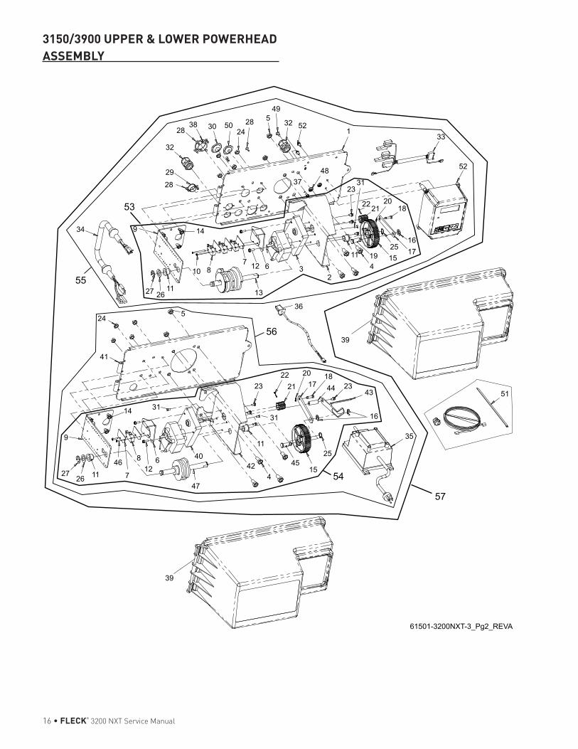
16 • FLECK® 3200 NXT Service Manual
3150/3900 UPPER & LOWER POWERHEAD ASSEMBLY
5
1
432
67
5
9
2726 11
46
7
812
6
47
4042
4
11
4515
25
35
16
432344
1817
20
2122
31
23
27 2611
10 8
13
1211 19 15
25 1716
24
34 9 14
2829
32
2838 30 50
2428
49
32 52
3748
2331
222120
18
33
52
61501-3200NXT-3_Pg2_REVA
39
39
51
41
3114
36
53
55
54
56
57
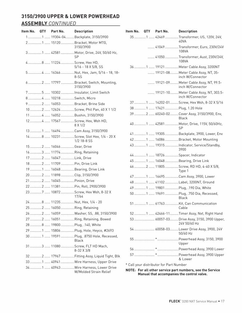
FLECK® 3200 NXT Service Manual • 17
Item No. QTY Part No. Description 1 ..............1 ...... 19304-04 .........Backplate, 3150/3900 2 ..............1 ...... 15120 ..............Bracket, Motor MTG,
3150/3900 3 ..............1 ...... 42581 ..............Motor, Drive, 24V, 50/60 Hz,
SP 4 ..............8 ...... 11224 ..............Screw, Hex HD,
5/16 - 18 X 5/8, SS 5 ..............4 ...... 16346 ..............Nut, Hex, Jam, 5/16 - 18, 18-
8-SS 6 ..............2 ...... 17797 ..............Bracket, Switch, Mounting,
3150/3900 7 ..............5 ...... 10302 ..............Insulator, Limit Switch 8 ..............4 ...... 10218 ..............Switch, Micro 9 ..............2 ...... 16053 ..............Bracket, Brine Side 10 ............2 ...... 12624 ..............Screw, Phil Pan, 40 X 1 1/2 11 ............4 ...... 16052 ..............Bushin, 3150/3900 12 ............4 ...... 17567 ..............Screw, Hex, Wsh HD,
8 X 1/2 13 ............1 ...... 16494 ..............Cam Assy, 3150/3900 14 ............8 ...... 10231 ..............Screw, Slot Hex, 1/4 - 20 X
1/2 18-8 SS 15 ............2 ...... 16046 ..............Gear, Drive 16 ............3 ...... 11774 ..............Ring, Retaining 17 ............2 ...... 16047 ..............Link, Drive 18 ............2 ...... 11709 ..............Pin, Drive Link 19 ............1 ...... 16048 ..............Bearing, Drive Link 20 ............2 ...... 11898 ..............Clip, 3150/3900 21 ............2 ...... 16045 ..............Pinion, Drive 22 ............2 ...... 11381 ..............Pin, Roll, 2900/3900 23 ............7 ...... 10872 ..............Screw, Hex Wsh, 8-32 X
17/64 24 ............8 ...... 11235 ..............Nut, Hex, 1/4 - 20 25 ............2 ...... 16050 ..............Ring, Retaining 26 ............2 ...... 16059 ..............Washer, SS, .88, 3150/3900 27 ............2 ...... 16051 ..............Ring, Retaining, Bowed 28 ............8 ...... 19800 ..............Plug, .140, White 29 ............1 ...... 15806 ..............Plug, Hole, Heyco, #2693 30 ............1 ...... 19591 ..............Plug, .8750 Hole, Recessed,
Black 31 ............3 ...... 11080 ..............Screw, FLT HD Mach,
8-32 X 3/8 32 ............2 ...... 17967 ..............Fitting Assy, Liquid Tight, Blk 33 ............1 ...... 40941 ..............Wire Harness, Upper Drive 34 ............1 ...... 40943 ..............Wire Harness, Lower Drive
W/Molded Strain Relief
35 ............1 ...... 42469 ..............Transformer, US, 120V, 24V, 40VA
....... 41049 ..............Transformer, Euro, 230V/24V 108VA
....... 41050 ..............Transformer, Aust, 230V/24V, 108VA
36 ............1 ...... 19121 ..............Meter Cable Assy, 3200NT ....... 19121-08 .........Meter Cable Assy, NT, 35-
inch W/Connector ....... 19121-09 .........Meter Cable Assy, NT, 99.5-
inch W/Connector ....... 19121-10 .........Meter Cable Assy, NT, 303.5-
inch W/Connector 37 ............1 ...... 14202-01 .........Screw, Hex Wsh, 8-32 X 5/16 38 ............1 ...... 17421 ..............Plug, 1.20 Hole 39 ............2 ...... 60240-02 .........Cover Assy, 3150/3900, Env,
Black 40 ............1 ...... 42581 ..............Motor, Drive, 115V, 50/60Hz,
SP 41 ............1 ...... 19305 ..............Backplate, 3900, Lower, Env 42 ............1 ...... 16086 ..............Bracket, Motor Mounting 43 ............1 ...... 19315 ..............Indicator, Service/Standby,
3900 44 ............1 ...... 18726 ..............Spacer, Indicator 45 ............1 ...... 16048 ..............Bearing, Drive Link 46 ............2 ...... 11805 ..............Screw, RD HD, 4-40 X 5/8,
Type 1 47 ............1 ...... 16495 ..............Cam Assy, 3900, Lower 48 ............1 ...... 41102 ..............Label, 3200NT, Ground 49 ............1 ...... 19801 ..............Plug, .190 Dia, White 50 ............1 ...... 19691 ..............Plug, .750 Dia, Recessed,
Black 51 ............1 ...... 61763 ..............Kit, Can Communication
Cable 52 ............1 ...... 42466-11 .........Timer Assy, Nxt, Right Hand 53 ..................... 60057-03 .........Drive Assy, 3150, 3900 Upper,
24V 50/60 Hz 54 ..................... 60058-03 .........Lower Drive Assy, 3900, 24V
50/60 Hz 55 ..................... * ......................Powerhead Assy, 3150, 3900
Upper 56 ..................... * ......................Powerhead Assy, 3900 Lower 57 ..................... * ......................Powerhead Assy, 3900 Upper
& Lower* Call your distributor for Part NumberNOTE: For all other service part numbers, see the Service
Manual that accompanies the control valve.
Item No. QTY Part No. Description
3150/3900 UPPER & LOWER POWERHEAD ASSEMBLY CONTINUED
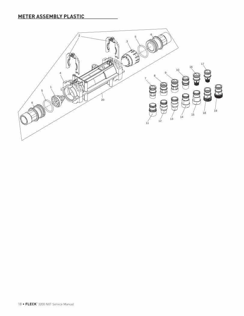
18 • FLECK® 3200 NXT Service Manual
METER ASSEMBLY PLASTIC
65
3
4
2
15
6
78
910
1112
1314
15
1617
1819
20
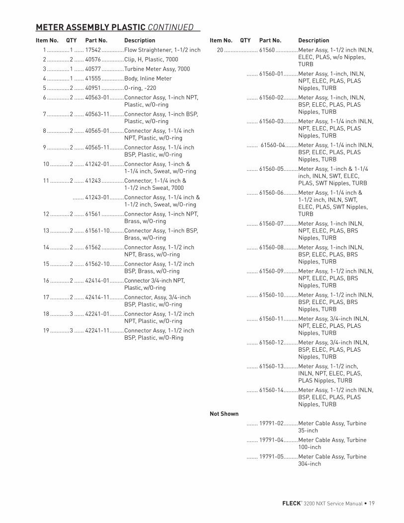
FLECK® 3200 NXT Service Manual • 19
Item No. QTY Part No. Description 1 ..............1 ...... 17542 ..............Flow Straightener, 1-1/2 inch 2 ..............2 ...... 40576 ..............Clip, H, Plastic, 7000 3 ..............1 ...... 40577 ..............Turbine Meter Assy, 7000 4 ..............1 ...... 41555 ..............Body, Inline Meter 5 ..............2 ...... 40951 ..............O-ring, -220 6 ..............2 ...... 40563-01 .........Connector Assy, 1-inch NPT,
Plastic, w/O-ring 7 ..............2 ...... 40563-11 .........Connector Assy, 1-inch BSP,
Plastic, w/O-ring 8 ..............2 ...... 40565-01 .........Connector Assy, 1-1/4 inch
NPT, Plastic, w/O-ring 9 ..............2 ...... 40565-11 .........Connector Assy, 1-1/4 inch
BSP, Plastic, w/O-ring 10 ............2 ...... 41242-01 .........Connector Assy, 1-inch &
1-1/4 inch, Sweat, w/O-ring 11 ............2 ...... 41243 ..............Connector, 1-1/4 inch &
1-1/2 inch Sweat, 7000 ....... 41243-01 .........Connector Assy, 1-1/4 inch &
1-1/2 inch, Sweat, w/O-ring 12 ............2 ...... 61561 ..............Connector Assy, 1-inch NPT,
Brass, w/O-ring 13 ............2 ...... 61561-10 .........Connector Assy, 1-inch BSP,
Brass, w/O-ring 14 ............2 ...... 61562 ..............Connector Assy, 1-1/2 inch
NPT, Brass, w/O-ring 15 ............2 ...... 61562-10 .........Connector Assy, 1-1/2 inch
BSP, Brass, w/O-ring 16 ............2 ...... 42414-01 .........Connector 3/4-inch NPT,
Plastic, w/O-ring 17 ............2 ...... 42414-11 .........Connector, Assy, 3/4-inch
BSP, Plastic, w/O-ring 18 ............3 ...... 42241-01 .........Connector Assy, 1-1/2 inch
NPT, Plastic, w/O-ring 19 ............3 ...... 42241-11 .........Connector Assy, 1-1/2 inch
BSP, Plastic, w/O-Ring
20 ..................... 61560 ..............Meter Assy, 1-1/2 inch INLN, ELEC, PLAS, w/o Nipples, TURB
....... 61560-01 .........Meter Assy, 1-inch, INLN, NPT, ELEC, PLAS, PLAS Nipples, TURB
....... 61560-02 .........Meter Assy, 1-inch, INLN, BSP, ELEC, PLAS, PLAS Nipples, TURB
....... 61560-03 .........Meter Assy, 1-1/4 inch INLN, NPT, ELEC, PLAS, PLAS Nipples, TURB
....... 61560-04 ........Meter Assy, 1-1/4 inch INLN, BSP, ELEC, PLAS, PLAS Nipples, TURB
....... 61560-05 .........Meter Assy, 1-inch & 1-1/4 inch, INLN, SWT, ELEC, PLAS, SWT Nipples, TURB
....... 61560-06 .........Meter Assy, 1-1/4 inch & 1-1/2 inch, INLN, SWT, ELEC, PLAS, SWT Nipples, TURB
....... 61560-07 .........Meter Assy, 1-inch INLN, NPT, ELEC, PLAS, BRS Nipples, TURB
....... 61560-08 .........Meter Assy, 1-inch INLN, BSP, ELEC, PLAS, BRS Nipples, TURB
....... 61560-09 .........Meter Assy, 1-1/2 inch INLN, NPT, ELEC, PLAS, BRS Nipples, TURB
....... 61560-10 .........Meter Assy, 1-1/2 inch INLN, BSP, ELEC, PLAS, BRS Nipples, TURB
....... 61560-11 .........Meter Assy, 3/4-inch INLN, NPT, ELEC, PLAS, PLAS Nipples, TURB
....... 61560-12 .........Meter Assy, 3/4-inch INLN, BSP, ELEC, PLAS, PLAS Nipples, TURB
....... 61560-13 .........Meter Assy, 1-1/2 inch, INLN, NPT, ELEC, PLAS, PLAS Nipples, TURB
....... 61560-14 .........Meter Assy, 1-1/2 inch INLN, BSP, ELEC, PLAS, PLAS Nipples, TURB
Not Shown ....... 19791-02 .........Meter Cable Assy, Turbine
35-inch ....... 19791-04 .........Meter Cable Assy, Turbine
100-inch ....... 19791-05 .........Meter Cable Assy, Turbine
304-inch
Item No. QTY Part No. Description
METER ASSEMBLY PLASTIC CONTINUED
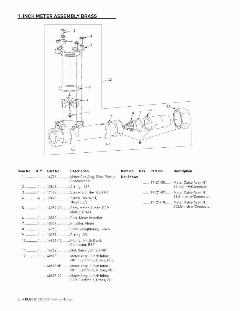
20 • FLECK® 3200 NXT Service Manual
1-INCH METER ASSEMBLY BRASS
Item No. QTY Part No. Description 1 ..............1 ...... 14716 ..............Meter Cap Assy, Elec, Plastic
Paddlewheel 2 ..............1 ...... 13847 ..............O-ring, -137 3 ..............1 ...... 17798 ..............Screw, Slot Hex WSH HD 4 ..............4 ...... 12473 ..............Screw, Hex WSH,
10-24 x 5/8 5 ..............1 ...... 14959-20 .........Body, Meter, 1-inch, BSP,
Metric, Brass 6 ..............1 ...... 13882 ..............Post, Meter Impeller 7 ..............1 ...... 13509 ..............Impeller, Meter 8 ..............1 ...... 14960 ..............Flow Straightener, 1-inch 9 ..............1 ...... 13287 ..............O-ring, 123 10 ............1 ...... 14961-10 .........Fitting, 1-inch Quick
Connector, BSP 11 ............1 ...... 14962 ..............Nut, Quick Connect NPT 12 ............1 ...... 60613 ..............Meter Assy, 1-inch Inline,
NPT, Electronic, Brass, PDL ....... 60613NP .........Meter Assy, 1-inch Inline,
NPT, Electronic, Nickel, PDL ....... 60613-20 .........Meter Assy, 1-inch Inline,
BSP, Electronic, Brass, PDL
6
7
1
3
4
2
109
11
12
85
5
Not Shown ....... 19121-08 .........Meter Cable Assy, NT,
35-inch, w/Connector ....... 19121-09 .........Meter Cable Assy, NT,
99.5-inch, w/Connector ....... 19121-10 .........Meter Cable Assy, NT,
303.5-inch w/Connector
Item No. QTY Part No. Description
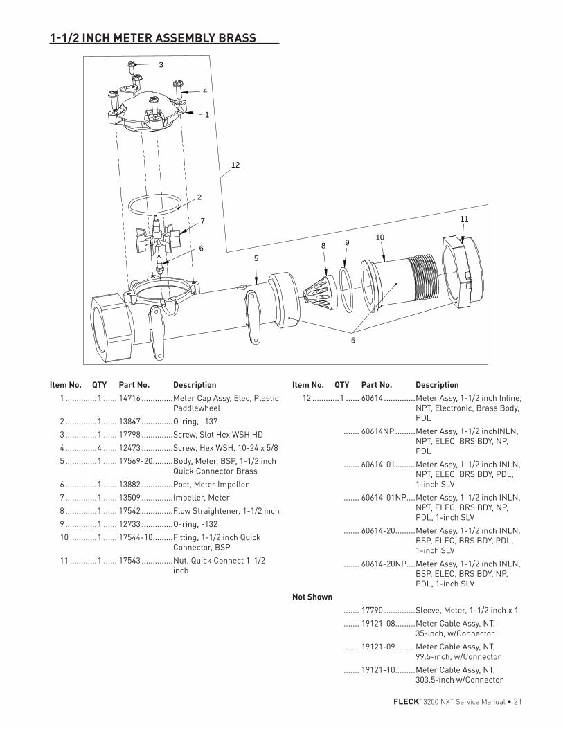
FLECK® 3200 NXT Service Manual • 21
1-1/2 INCH METER ASSEMBLY BRASS
Item No. QTY Part No. Description 1 ..............1 ...... 14716 ..............Meter Cap Assy, Elec, Plastic
Paddlewheel 2 ..............1 ...... 13847 ..............O-ring, -137 3 ..............1 ...... 17798 ..............Screw, Slot Hex WSH HD 4 ..............4 ...... 12473 ..............Screw, Hex WSH, 10-24 x 5/8 5 ..............1 ...... 17569-20 .........Body, Meter, BSP, 1-1/2 inch
Quick Connector Brass 6 ..............1 ...... 13882 ..............Post, Meter Impeller 7 ..............1 ...... 13509 ..............Impeller, Meter 8 ..............1 ...... 17542 ..............Flow Straightener, 1-1/2 inch 9 ..............1 ...... 12733 ..............O-ring, -132 10 ............1 ...... 17544-10 .........Fitting, 1-1/2 inch Quick
Connector, BSP 11 ............1 ...... 17543 ..............Nut, Quick Connect 1-1/2
inch
5
6
1
12
11
8 910
5
4
3
7
2
12 ............1 ...... 60614 ..............Meter Assy, 1-1/2 inch Inline, NPT, Electronic, Brass Body, PDL
....... 60614NP .........Meter Assy, 1-1/2 inchINLN, NPT, ELEC, BRS BDY, NP, PDL
....... 60614-01 .........Meter Assy, 1-1/2 inch INLN, NPT, ELEC, BRS BDY, PDL, 1-inch SLV
....... 60614-01NP....Meter Assy, 1-1/2 inch INLN, NPT, ELEC, BRS BDY, NP, PDL, 1-inch SLV
....... 60614-20 .........Meter Assy, 1-1/2 inch INLN, BSP, ELEC, BRS BDY, PDL, 1-inch SLV
....... 60614-20NP....Meter Assy, 1-1/2 inch INLN, BSP, ELEC, BRS BDY, NP, PDL, 1-inch SLV
Not Shown ....... 17790 ..............Sleeve, Meter, 1-1/2 inch x 1 ....... 19121-08 .........Meter Cable Assy, NT,
35-inch, w/Connector ....... 19121-09 .........Meter Cable Assy, NT,
99.5-inch, w/Connector ....... 19121-10 .........Meter Cable Assy, NT,
303.5-inch w/Connector
Item No. QTY Part No. Description
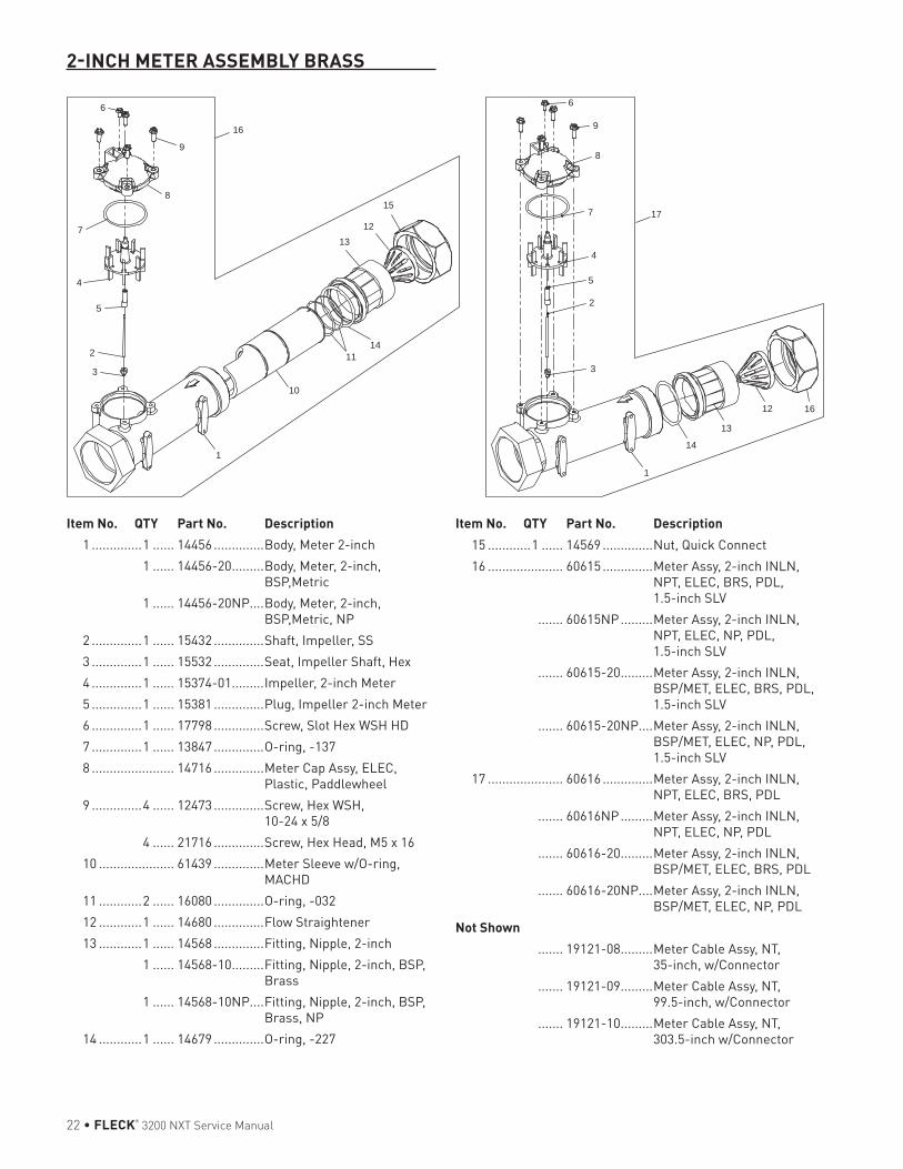
22 • FLECK® 3200 NXT Service Manual
2-INCH METER ASSEMBLY BRASS
Item No. QTY Part No. Description 1 ..............1 ...... 14456 ..............Body, Meter 2-inch 1 ...... 14456-20 .........Body, Meter, 2-inch,
BSP,Metric 1 ...... 14456-20NP....Body, Meter, 2-inch,
BSP,Metric, NP 2 ..............1 ...... 15432 ..............Shaft, Impeller, SS 3 ..............1 ...... 15532 ..............Seat, Impeller Shaft, Hex 4 ..............1 ...... 15374-01 .........Impeller, 2-inch Meter 5 ..............1 ...... 15381 ..............Plug, Impeller 2-inch Meter 6 ..............1 ...... 17798 ..............Screw, Slot Hex WSH HD 7 ..............1 ...... 13847 ..............O-ring, -137 8 ....................... 14716 ..............Meter Cap Assy, ELEC,
Plastic, Paddlewheel 9 ..............4 ...... 12473 ..............Screw, Hex WSH,
10-24 x 5/8 4 ...... 21716 ..............Screw, Hex Head, M5 x 16 10 ..................... 61439 ..............Meter Sleeve w/O-ring,
MACHD 11 ............2 ...... 16080 ..............O-ring, -032 12 ............1 ...... 14680 ..............Flow Straightener 13 ............1 ...... 14568 ..............Fitting, Nipple, 2-inch 1 ...... 14568-10 .........Fitting, Nipple, 2-inch, BSP,
Brass 1 ...... 14568-10NP....Fitting, Nipple, 2-inch, BSP,
Brass, NP 14 ............1 ...... 14679 ..............O-ring, -227
1
7
15
16
13
3
2
5
4
6
8
11
12
9
10
14
12 16
13
14
1
3
2
5
4
6
8
9
7 17
15 ............1 ...... 14569 ..............Nut, Quick Connect 16 ..................... 60615 ..............Meter Assy, 2-inch INLN,
NPT, ELEC, BRS, PDL, 1.5-inch SLV
....... 60615NP .........Meter Assy, 2-inch INLN, NPT, ELEC, NP, PDL, 1.5-inch SLV
....... 60615-20 .........Meter Assy, 2-inch INLN, BSP/MET, ELEC, BRS, PDL, 1.5-inch SLV
....... 60615-20NP....Meter Assy, 2-inch INLN, BSP/MET, ELEC, NP, PDL, 1.5-inch SLV
17 ..................... 60616 ..............Meter Assy, 2-inch INLN, NPT, ELEC, BRS, PDL
....... 60616NP .........Meter Assy, 2-inch INLN, NPT, ELEC, NP, PDL
....... 60616-20 .........Meter Assy, 2-inch INLN, BSP/MET, ELEC, BRS, PDL
....... 60616-20NP....Meter Assy, 2-inch INLN, BSP/MET, ELEC, NP, PDL
Not Shown ....... 19121-08 .........Meter Cable Assy, NT,
35-inch, w/Connector ....... 19121-09 .........Meter Cable Assy, NT,
99.5-inch, w/Connector ....... 19121-10 .........Meter Cable Assy, NT,
303.5-inch w/Connector
Item No. QTY Part No. Description
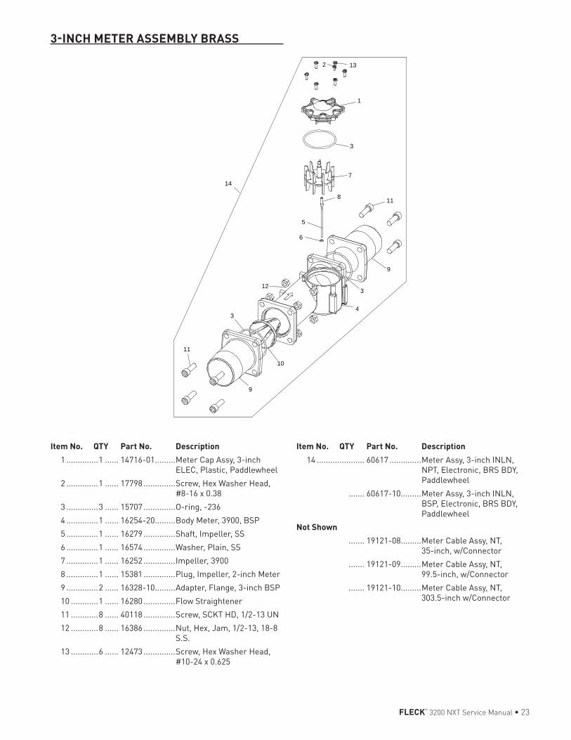
FLECK® 3200 NXT Service Manual • 23
3-INCH METER ASSEMBLY BRASS
Item No. QTY Part No. Description 1 ..............1 ...... 14716-01 .........Meter Cap Assy, 3-inch
ELEC, Plastic, Paddlewheel 2 ..............1 ...... 17798 ..............Screw, Hex Washer Head,
#8-16 x 0.38 3 ..............3 ...... 15707 ..............O-ring, -236 4 ..............1 ...... 16254-20 .........Body Meter, 3900, BSP 5 ..............1 ...... 16279 ..............Shaft, Impeller, SS 6 ..............1 ...... 16574 ..............Washer, Plain, SS 7 ..............1 ...... 16252 ..............Impeller, 3900 8 ..............1 ...... 15381 ..............Plug, Impeller, 2-inch Meter 9 ..............2 ...... 16328-10 .........Adapter, Flange, 3-inch BSP 10 ............1 ...... 16280 ..............Flow Straightener 11 ............8 ...... 40118 ..............Screw, SCKT HD, 1/2-13 UN 12 ............8 ...... 16386 ..............Nut, Hex, Jam, 1/2-13, 18-8
S.S. 13 ............6 ...... 12473 ..............Screw, Hex Washer Head,
#10-24 x 0.625
132
1
7
118
9
5
6
4
10
12
3
3
3
9
11
14
14 ..................... 60617 ..............Meter Assy, 3-inch INLN, NPT, Electronic, BRS BDY, Paddlewheel
....... 60617-10 .........Meter Assy, 3-inch INLN, BSP, Electronic, BRS BDY, Paddlewheel
Not Shown ....... 19121-08 .........Meter Cable Assy, NT,
35-inch, w/Connector ....... 19121-09 .........Meter Cable Assy, NT,
99.5-inch, w/Connector ....... 19121-10 .........Meter Cable Assy, NT,
303.5-inch w/Connector
Item No. QTY Part No. Description
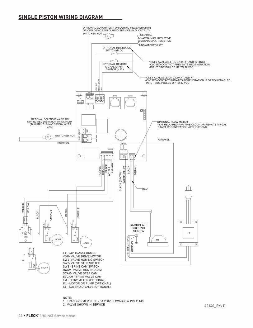
24 • FLECK® 3200 NXT Service Manual
SINGLE PISTON WIRING DIAGRAM
BVCAM
HCAM
SCAM
M1C
N.O
.
N.C
.SW
1VDMFM
C
N.O
.
N.C
.SW
3
C
N.O
.
N.C
.SW
2
S1
T1 - 24V TRANSFORMERVDM- VALVE DRIVE MOTORSW1- VALVE HOMING SWITCHSW2- VALVE STEP SWITCHSW3 - BRINE CAM SWITCHHCAM- VALVE HOMING CAMSCAM- VALVE STEP CAMBVCAM - BRINE VALVE CAMFM - FLOW METER (OPTIONAL)M1 - MOTOR OR PUMP (OPTIONAL)S1 - SOLENOID VALVE (OPTIONAL)
NOTE: 1. TRANSFORMER FUSE - 5A 250V SLOW-BLOW P/N 411432. VALVE SHOWN IN SERVICE
T1
WT/
BLK
YE
LLO
W
BLA
CK
OR
AN
GE
BLA
CK
PU
RP
LE
PU
RP
LEO
RA
NG
EB
LAC
K
YE
LLO
WW
T/B
LK
BLA
CK
(BR
OW
N)
WH
ITE
(BLU
E)
BLA
CK
GR
EE
N
RED
GR
N O
R G
RN
/YE
L
GR
N/Y
EL
BACKPLATEGROUND SCREW
GRN/YELSWITCHED HOT
NEUTRAL
OPTIONAL SOLENOID VALVE ON DURING REGENERATION OR STANDBY (P6 OUTPUT - 24VAC 50/60Hz, 0.25 A,
MAX.)
OPTIONAL INTERLOCK SWITCH (N.O.)
UNSWITCHED HOT
24VAC/3A MAX. RESISTIVE30VDC/3A MAX. RESISTIVE
NEUTRALSWITCHED HOT
OPTIONAL MOTOR/PUMP ON DURING REGENERATION OR CPO DEVICE ON DURING SERVICE (N.O. OUTPUT)
OPTIONAL REMOTESIGNAL START SWITCH (N.O.)
*ONLY AVAILABLE ON 3200NXT AND 3214NXT-CLOSED CONTACT PREVENTS REGENERATION-INPUT SIDE PULLED UP TO 32 VDC
*ONLY AVAILABLE ON 3200NXT AND XT-CLOSED CONTACT INITIATES REGENERATION IF OPTION ENABLED-INPUT SIDE PULLED UP TO 32 VDC
CAN1 CAN2
METER
24V AC
UPPER DRIVE
LOW
PE
RD
RIV
E
LOC
K O
UT
RE
MO
TE S
TAR
T
GN
D
AUX
F1
OPTIONAL FLOW METER-NOT REQUIRED FOR TIME CLOCK OR REMOTE SINGAL START REGENERATION APPLICATIONS.
42140_Rev D
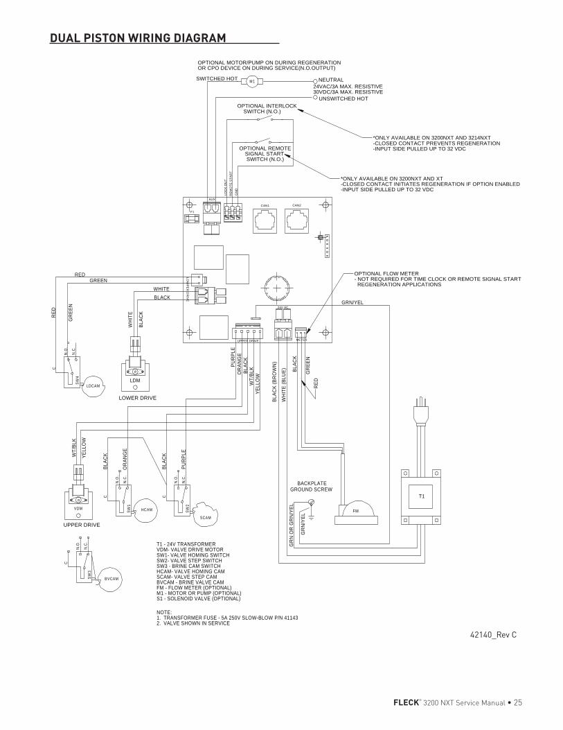
FLECK® 3200 NXT Service Manual • 25
DUAL PISTON WIRING DIAGRAM
BVCAM
SCAM
M1
VDM FM
C
N.O
.
N.C
.SW
3
C
N.O
.
N.C
.SW
2
HCAM
C
N.O
.
N.C
.SW
1
T1 - 24V TRANSFORMERVDM- VALVE DRIVE MOTORSW1- VALVE HOMING SWITCHSW2- VALVE STEP SWITCHSW3 - BRINE CAM SWITCHHCAM- VALVE HOMING CAMSCAM- VALVE STEP CAMBVCAM - BRINE VALVE CAMFM - FLOW METER (OPTIONAL)M1 - MOTOR OR PUMP (OPTIONAL)S1 - SOLENOID VALVE (OPTIONAL)
NOTE: 1. TRANSFORMER FUSE - 5A 250V SLOW-BLOW P/N 411432. VALVE SHOWN IN SERVICE
PUR
PLE
BLAC
K
YELL
OW
BLAC
K (B
RO
WN
)
GR
N/Y
EL
WT/
BLK
UNSWITCHED HOT
BLAC
K
WT/
BLK
OR
ANG
E
WH
ITE
(BLU
E)
NEUTRALYE
LLO
W
PUR
PLE
GR
N O
R G
RN
/YEL
T1
BACKPLATE GROUND SCREW
GRN/YEL
OPTIONAL INTERLOCK SWITCH (N.O.)
24VAC/3A MAX. RESISTIVE30VDC/3A MAX. RESISTIVE
SWITCHED HOT
BLAC
K
OR
ANG
E
RED
WH
ITE
BLAC
K
C
N.O
.
N.C
.SW
4G
REE
N
LDCAMLDM
RED
BLACKWHITE
GREEN
LOWER DRIVE
UPPER DRIVE
BLAC
K
RED
GR
EEN
OPTIONAL MOTOR/PUMP ON DURING REGENERATION OR CPO DEVICE ON DURING SERVICE(N.O.OUTPUT)
*ONLY AVAILABLE ON 3200NXT AND 3214NXT-CLOSED CONTACT PREVENTS REGENERATION-INPUT SIDE PULLED UP TO 32 VDCOPTIONAL REMOTE
SIGNAL START SWITCH (N.O.)
*ONLY AVAILABLE ON 3200NXT AND XT-CLOSED CONTACT INITIATES REGENERATION IF OPTION ENABLED-INPUT SIDE PULLED UP TO 32 VDC
CAN2CAN1
RE
MO
TE S
TAR
T
GN
D
LOC
K O
UT
AUX
LOW
PE
RD
RIV
E
UPPER DRIVE
24V AC
METER
F1
OPTIONAL FLOW METER- NOT REQUIRED FOR TIME CLOCK OR REMOTE SIGNAL START REGENERATION APPLICATIONS
42140_Rev C
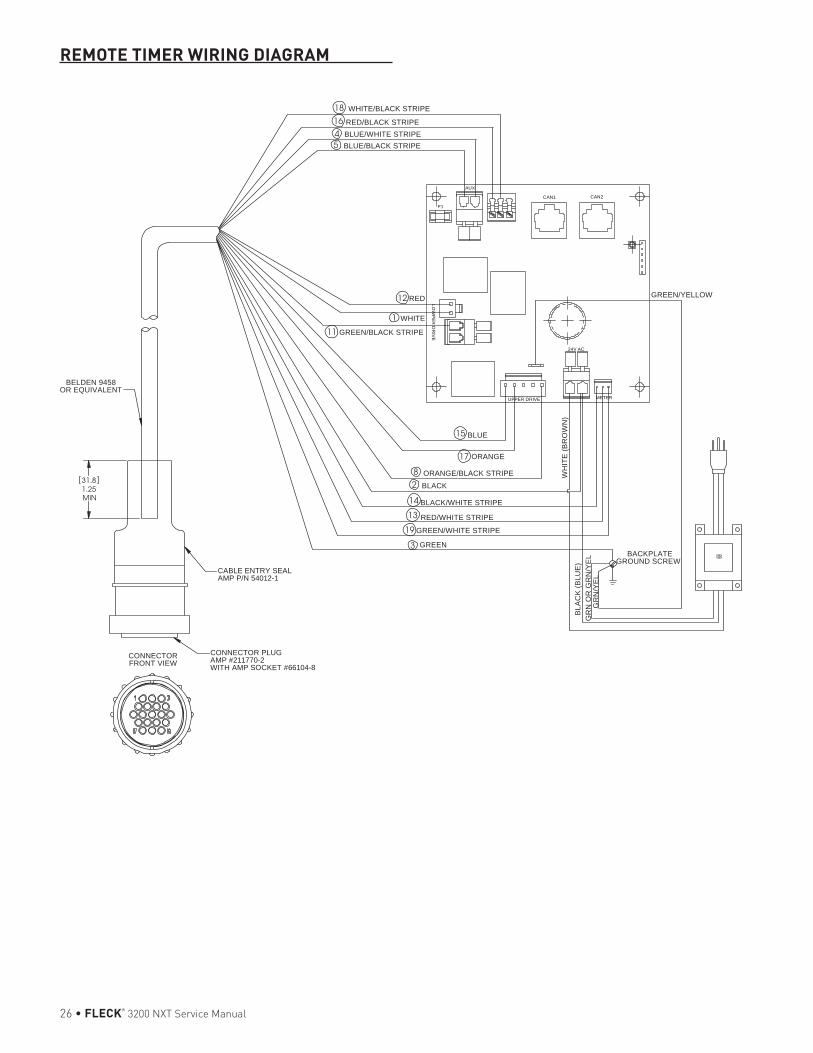
26 • FLECK® 3200 NXT Service Manual
REMOTE TIMER WIRING DIAGRAM
1.25MIN
31.8
GREEN/YELLOW
BACKPLATE GROUND SCREW
WHITE
GREEN/BLACK STRIPE
RED
��
GR
N O
R G
RN
/YE
LB
LAC
K (B
LUE
)
GR
N/Y
EL
WH
ITE
(BR
OW
N)
BLUE
ORANGE
ORANGE/BLACK STRIPE
BLACK
BLACK/WHITE STRIPE
RED/WHITE STRIPE
GREEN/WHITE STRIPE
WHITE/BLACK STRIPE
RED/BLACK STRIPE
BLUE/BLACK STRIPEBLUE/WHITE STRIPE
GREEN3
19
13
14
28
17
15
12
11
1
18
1645
CONNECTORFRONT VIEW
BELDEN 9458OR EQUIVALENT
CABLE ENTRY SEALAMP P/N 54012-1
CONNECTOR PLUGAMP #211770-2WITH AMP SOCKET #66104-8
CAN2CAN1
AUX
LOW
PE
RD
RIV
E
UPPER DRIVE
24V AC
METER
F1
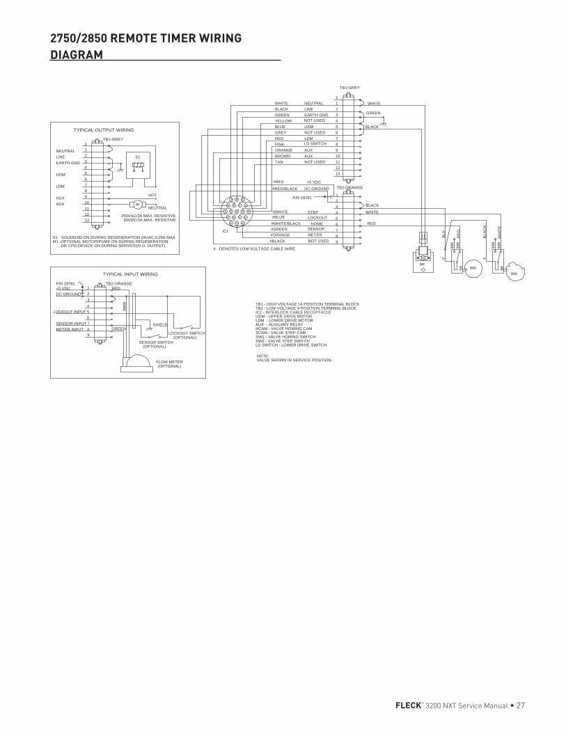
FLECK® 3200 NXT Service Manual • 27
2750/2850 REMOTE TIMER WIRING DIAGRAM
NOTE:VALVE SHOWN IN SERVICE POSITION.
TB1 - HIGH VOLTAGE 14 POSITION TERMINAL BLOCKTB2 - LOW VOLTAGE 9 POSITION TERMINAL BLOCKIC1 - INTERLOCK CABLE RECEPTACLEUDM - UPPER DRIVE MOTORLDM - LOWER DRIVE MOTORAUX - AUXILARY RELAYHCAM - VALVE HOMING CAMSCAM - VALVE STEP CAMSW1 - VALVE HOMING SWITCHSW2 - VALVE STEP SWITCHLD SWITCH - LOWER DRIVE SWITCH
TYPICAL INPUT WIRING
LOCKOUT SWITCH
SENSOR SWITCH
LOCKOUT INPUT
RED
GREENMETER INPUTSENSOR INPUT
(OPTIONAL)
(OPTIONAL)
TB2-ORANGE
SHIELD
(OPTIONAL)
2
5
1
4
87
DC GROUND+5 VDC
FLOW METER
3
6
9
P/N 19781
����
�
����
����
�
����
����
���
�
����
����
���
���
�� �� �� ��
�� �� ��
��������
� � � �
� � �
BLK
TAN
PINK
BLUE
HOME
P/N 19781
NOT USED
UDM
LINE
RED
BLACK
BLACK
IC1
REDGREY
METER
STEP
AUX
LDM
WHITE
GREEN
WHITE
RE
D
BLA
CK
+5 VDC
#BLACK NOT USED 9
#WHITE/BLACK 6
3
DC GROUND#RED/BLACK
11
8
5
2KCALB
#ORANGE 8
#GREEN SENSOR 7
2
#WHITE 4
1
TB2-ORANGE
13
01NWORB
12
AUX 9EGNARO
7
4WOLLEY
NOT USED 6
EARTH GND 3NEERG
WHITE NEUTRAL 11
TB1-GREY
WH
ITE
#BLUE LOCKOUT 5
#RED
# - DENOTES LOW VOLTAGE CABLE WIRE
NOT USED
LD SWITCH
��
1NEUTRAL
7LDM
13
TYPICAL OUTPUT WIRING
1
3EARTH GND
6
4
AUX 9
12
10AUX
S1 - SOLENOID ON DURING REGENERATION 24VAC,0.25A MAXM1 -OPTIONAL MOTOR/PUMP ON DURING REGENERATION OR CPO DEVICE ON DURING SERVICE(N.O. OUTPUT)
2
5UDM
8
11
TB1-GREY
LINE S1
HOT
NEUTRAL
250VAC/3A MAX. RESISTIVE 30VDC/3A MAX. RESISTIVE
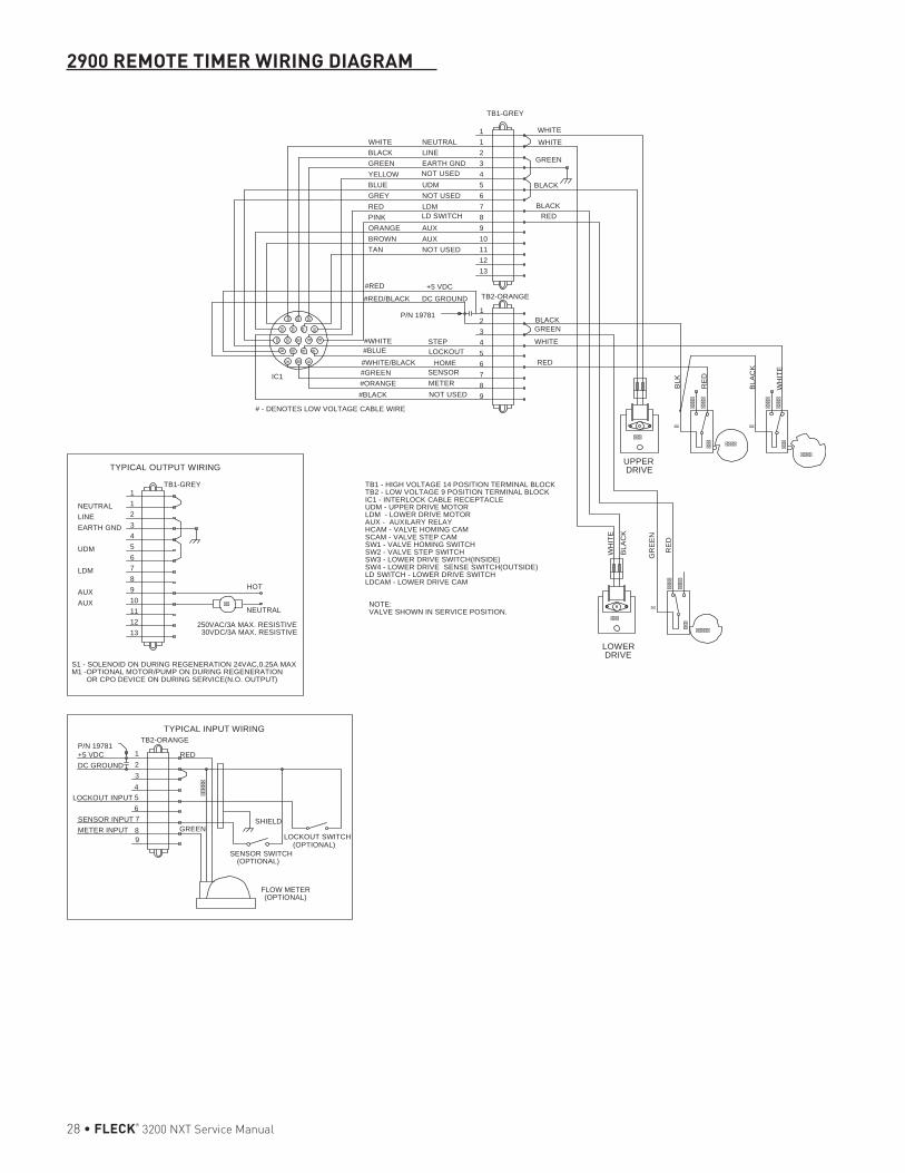
28 • FLECK® 3200 NXT Service Manual
2900 REMOTE TIMER WIRING DIAGRAM
NOTE:VALVE SHOWN IN SERVICE POSITION.
TB1 - HIGH VOLTAGE 14 POSITION TERMINAL BLOCKTB2 - LOW VOLTAGE 9 POSITION TERMINAL BLOCKIC1 - INTERLOCK CABLE RECEPTACLEUDM - UPPER DRIVE MOTORLDM - LOWER DRIVE MOTORAUX - AUXILARY RELAYHCAM - VALVE HOMING CAMSCAM - VALVE STEP CAMSW1 - VALVE HOMING SWITCHSW2 - VALVE STEP SWITCHSW3 - LOWER DRIVE SWITCH(INSIDE)SW4 - LOWER DRIVE SENSE SWITCH(OUTSIDE)LD SWITCH - LOWER DRIVE SWITCHLDCAM - LOWER DRIVE CAM
��
1NEUTRAL
7LDM
13
TYPICAL OUTPUT WIRING
1
3EARTH GND
6
4
AUX 9
12
10AUX
S1 - SOLENOID ON DURING REGENERATION 24VAC,0.25A MAXM1 -OPTIONAL MOTOR/PUMP ON DURING REGENERATION OR CPO DEVICE ON DURING SERVICE(N.O. OUTPUT)
2
5UDM
8
11
TB1-GREY
LINE
HOT
NEUTRAL
250VAC/3A MAX. RESISTIVE 30VDC/3A MAX. RESISTIVE
����
����
�
����
����
���
�
����
����
���
���
�� �� �� ��
�� �� ��
��������
� � � �
� � �
���
�����
�
����
����
���
BLK
TAN
PINK
BLUE
HOME
P/N 19781
NOT USED
UDM
LINE
RED
GREEN
BLACK
IC1
REDGREY
METER
STEP
AUX
LDM
WHITE
GREEN
WHITE
RE
D
BLA
CK
+5 VDC
#BLACK NOT USED 9
#WHITE/BLACK 6
3
DC GROUND#RED/BLACK
11
8
5
2KCALB
#ORANGE 8
#GREEN SENSOR 7
2
#WHITE 4
1
TB2-ORANGE
13
01NWORB
12
AUX 9EGNARO
7
4WOLLEY
NOT USED 6
EARTH GND 3NEERG
WHITE NEUTRAL 11
TB1-GREY
WH
ITE
#BLUE LOCKOUT 5
#RED
# - DENOTES LOW VOLTAGE CABLE WIRE
NOT USED
LD SWITCH
WHITE
BLACK
UPPER DRIVE
BLA
CK
WH
ITE
RE
D
GR
EE
NLOWER DRIVE
BLACKRED
����
�
P/N 19781
9
6
3
FLOW METER
+5 VDCDC GROUND
78
4
1
5
2
(OPTIONAL)
SHIELD
TB2-ORANGE
(OPTIONAL)
(OPTIONAL)
SENSOR INPUTMETER INPUT GREEN
RED
LOCKOUT INPUT
SENSOR SWITCH
LOCKOUT SWITCH
TYPICAL INPUT WIRING
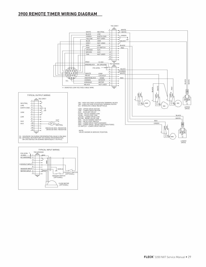
FLECK® 3200 NXT Service Manual • 29
3900 REMOTE TIMER WIRING DIAGRAM
NOTE:VALVE SHOWN IN SERVICE POSITION.
TB1 - HIGH VOLTAGE 14 POSITION TERMINAL BLOCKTB2 - LOW VOLTAGE 9 POSITION TERMINAL BLOCKIC1 - INTERLOCK CABLE RECEPTACLE
UDM - UPPER DRIVE MOTORLDM - LOWER DRIVE MOTORAUX - AUXILARY RELAYHCAM - VALVE HOMING CAMSCAM - VALVE STEP CAMLDCAM - LOWER DRIVE CAMBVCAM - BRINE VALVE CAMSW1 - VALVE HOMING SWITCHSW2 - VALVE STEP SWITCHSW3 - LOWER DRIVE SWITCH(INSIDE)SW4 - LOWER DRIVE SENSE SWITCH(OUTSIDE)LD SWITCH - LOWER DRIVE SWITCH
��
1NEUTRAL
7LDM
13
TYPICAL OUTPUT WIRING
1
3EARTH GND
6
4
AUX 9
12
10AUX
S1 - SOLENOID ON DURING REGENERATION 24VAC,0.25A MAXM1 -OPTIONAL MOTOR/PUMP ON DURING REGENERATION OR CPO DEVICE ON DURING SERVICE(N.O. OUTPUT)
2
5UDM
8
11
TB1-GREY
LINE
HOT
NEUTRAL
250VAC/3A MAX. RESISTIVE 30VDC/3A MAX. RESISTIVE
����
�
P/N 19781
9
6
3
FLOW METER
+5 VDCDC GROUND
78
4
1
5
2
(OPTIONAL)
SHIELD
TB2-ORANGE
(OPTIONAL)
(OPTIONAL)
SENSOR INPUTMETER INPUT GREEN
RED
LOCKOUT INPUT
SENSOR SWITCH
LOCKOUT SWITCH
TYPICAL INPUT WIRING
�� �� �� ��
�� �� ��
��������
� � � �
� � �
�
����
����
���
�
����
����
���
�
����
����
���
�������
����
�����
�
����
����
���
�����
���
TAN
PINK
BLUE
HOME
P/N 19781
NOT USED
UDM
LINE
RED
BLACK
IC1
REDGREY
METER
STEP
AUX
LDM
WHITE
GREEN
WHITE
+5 VDC
#BLACK NOT USED 9
#WHITE/BLACK 6
3
DC GROUND#RED/BLACK
11
8
5
2KCALB
#ORANGE 8
#GREEN SENSOR 7
2
#WHITE 4
1
TB2-ORANGE
13
01NWORB
12
AUX 9EGNARO
7
4WOLLEY
NOT USED 6
EARTH GND 3NEERG
WHITE NEUTRAL 11
TB1-GREY
#BLUE LOCKOUT 5
#RED
# - DENOTES LOW VOLTAGE CABLE WIRE
NOT USED
BLACK
WH
ITE
BLA
CK
RE
D
LD SWITCH
WH
ITE
BLA
CK
LOWER DRIVE
WHITE
UPPER DRIVE
BLACKRED
GREEN
BLACK
WHITE
RED
GREEN
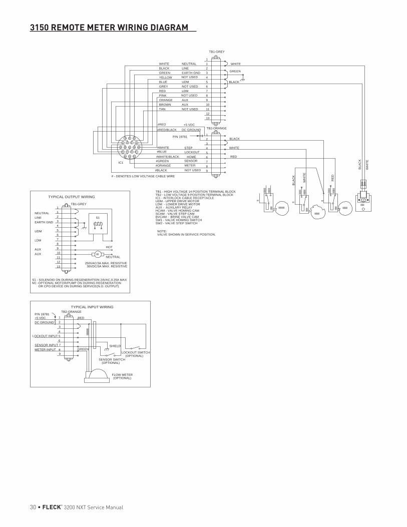
30 • FLECK® 3200 NXT Service Manual
3150 REMOTE METER WIRING DIAGRAM
NOTE:VALVE SHOWN IN SERVICE POSITION.
TB1 - HIGH VOLTAGE 14 POSITION TERMINAL BLOCKTB2 - LOW VOLTAGE 9 POSITION TERMINAL BLOCKIC1 - INTERLOCK CABLE RECEPTACLEUDM - UPPER DRIVE MOTORLDM - LOWER DRIVE MOTORAUX - AUXILARY RELAYHCAM - VALVE HOMING CAMSCAM - VALVE STEP CAMBVCAM - BRINE VALVE CAMSW1 - VALVE HOMING SWITCHSW2 - VALVE STEP SWITCH
��
1NEUTRAL
7LDM
13
TYPICAL OUTPUT WIRING
1
3EARTH GND
6
4
AUX 9
12
10AUX
S1 - SOLENOID ON DURING REGENERATION 24VAC,0.25A MAXM1 -OPTIONAL MOTOR/PUMP ON DURING REGENERATION OR CPO DEVICE ON DURING SERVICE(N.O. OUTPUT)
2
5UDM
8
11
TB1-GREY
LINE S1
HOT
NEUTRAL
250VAC/3A MAX. RESISTIVE 30VDC/3A MAX. RESISTIVE
����
�
P/N 19781
9
6
3
FLOW METER
+5 VDCDC GROUND
78
4
1
5
2
(OPTIONAL)
SHIELD
TB2-ORANGE
(OPTIONAL)
(OPTIONAL)
SENSOR INPUTMETER INPUT GREEN
RED
LOCKOUT INPUT
SENSOR SWITCH
LOCKOUT SWITCH
TYPICAL INPUT WIRING
�� �� �� ��
�� �� ��
��������
� � � �
� � �
�
����
����
���
�
����
����
���
�
����
����
���
�������
����
�����
TAN
PINK
BLUE
HOME
P/N 19781
NOT USED
UDM
LINE
RED
BLACK
IC1
REDGREY
METER
STEP
AUX
LDM
WHITE
GREEN
WHITE
+5 VDC
#BLACK NOT USED 9
#WHITE/BLACK 6
3
DC GROUND#RED/BLACK
11
8
5
2KCALB
#ORANGE 8
#GREEN SENSOR 7
2
#WHITE 4
1
TB2-ORANGE
13
01NWORB
12
AUX 9EGNARO
7
4WOLLEY
NOT USED 6
EARTH GND 3NEERG
WHITE NEUTRAL 11
TB1-GREY
#BLUE LOCKOUT 5
#RED
# - DENOTES LOW VOLTAGE CABLE WIRE
NOT USED
BLACK
WH
ITE
BLA
CK
RE
D
NOT USED
WH
ITE
BLA
CK
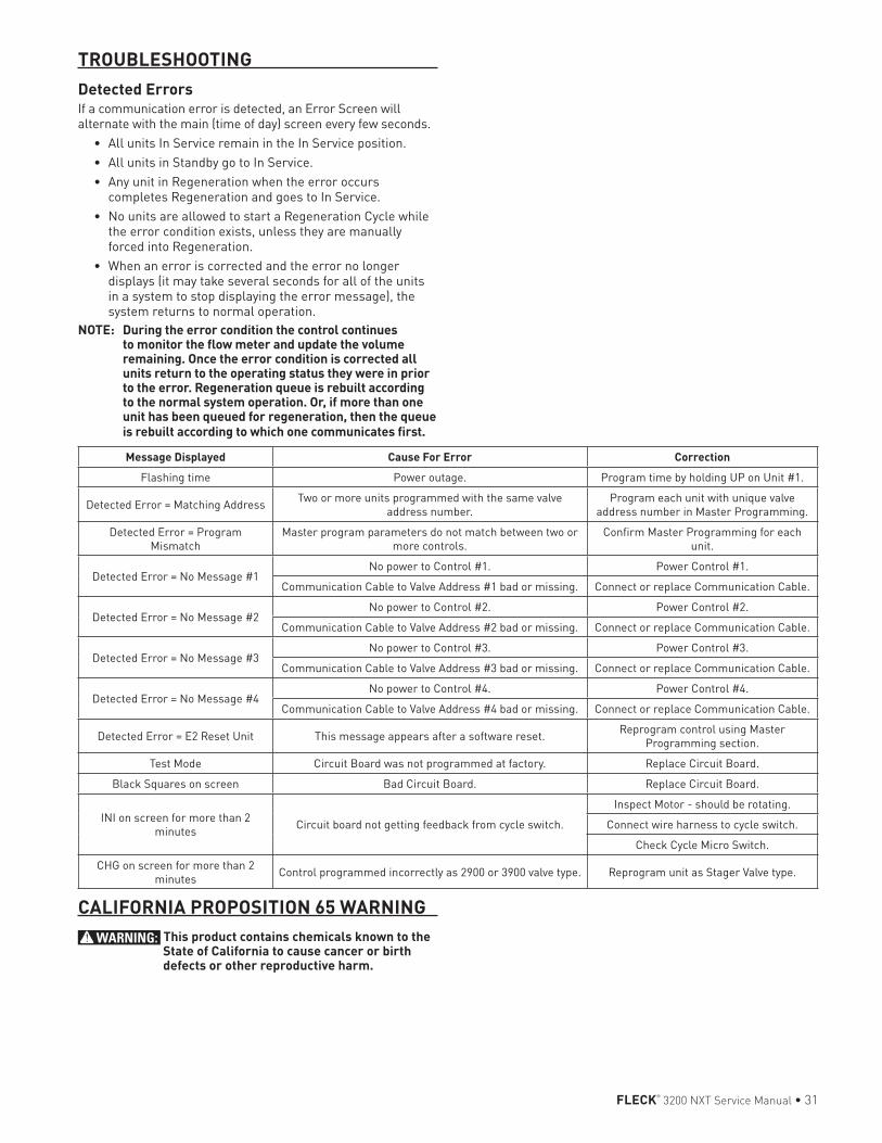
FLECK® 3200 NXT Service Manual • 31
TROUBLESHOOTINGDetected ErrorsIf a communication error is detected, an Error Screen will alternate with the main (time of day) screen every few seconds.
• All units In Service remain in the In Service position.• All units in Standby go to In Service.• Any unit in Regeneration when the error occurs
completes Regeneration and goes to In Service.• No units are allowed to start a Regeneration Cycle while
the error condition exists, unless they are manually forced into Regeneration.
• When an error is corrected and the error no longer displays (it may take several seconds for all of the units in a system to stop displaying the error message), the system returns to normal operation.
NOTE: During the error condition the control continues to monitor the flow meter and update the volume remaining. Once the error condition is corrected all units return to the operating status they were in prior to the error. Regeneration queue is rebuilt according to the normal system operation. Or, if more than one unit has been queued for regeneration, then the queue is rebuilt according to which one communicates first.
Message Displayed Cause For Error CorrectionFlashing time Power outage. Program time by holding UP on Unit #1.
Detected Error = Matching Address Two or more units programmed with the same valve address number.
Program each unit with unique valve address number in Master Programming.
Detected Error = Program Mismatch
Master program parameters do not match between two or more controls.
Confirm Master Programming for each unit.
Detected Error = No Message #1No power to Control #1. Power Control #1.
Communication Cable to Valve Address #1 bad or missing. Connect or replace Communication Cable.
Detected Error = No Message #2No power to Control #2. Power Control #2.
Communication Cable to Valve Address #2 bad or missing. Connect or replace Communication Cable.
Detected Error = No Message #3No power to Control #3. Power Control #3.
Communication Cable to Valve Address #3 bad or missing. Connect or replace Communication Cable.
Detected Error = No Message #4No power to Control #4. Power Control #4.
Communication Cable to Valve Address #4 bad or missing. Connect or replace Communication Cable.
Detected Error = E2 Reset Unit This message appears after a software reset. Reprogram control using Master Programming section.
Test Mode Circuit Board was not programmed at factory. Replace Circuit Board.
Black Squares on screen Bad Circuit Board. Replace Circuit Board.
INI on screen for more than 2 minutes Circuit board not getting feedback from cycle switch.
Inspect Motor - should be rotating.
Connect wire harness to cycle switch.
Check Cycle Micro Switch.
CHG on screen for more than 2 minutes Control programmed incorrectly as 2900 or 3900 valve type. Reprogram unit as Stager Valve type.
CALIFORNIA PROPOSITION 65 WARNINGWARNING: This product contains chemicals known to the
State of California to cause cancer or birth defects or other reproductive harm.

FILTRATION & PROCESSING SOLUTIONS5730 NORTH GLEN PARK ROAD, MILWAUKEE, WI 53209 P: 262.238.4400 | WWW.PENTAIRAQUA.COM | CUSTOMER CARE: 800.279.9404 | [email protected]
All Pentair trademarks and logos are owned by Pentair, Inc. or its affiliates. All other registered and unregistered trademarks and logos are the property of their respective owners. Because we are continuously improving our products and services. Pentair reserves the right to change specifications without prior notice. Pentair is an equal opportunity employer.41693 REV J FE13 © 2013 Pentair Residential Filtration, LLC All Rights Reserved.
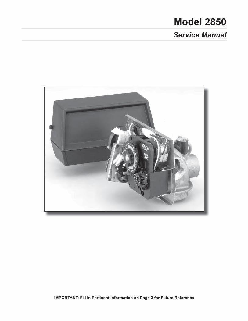
Model 2850
Service Manual
IMPORTANT: Fill in Pertinent Information on Page 3 for Future Reference
Job Specification Sheet ......................................................................................................................................... 3
Installation Instructions .......................................................................................................................................... 4
Start-Up Instructions .............................................................................................................................................. 5
3200 Timer Setting Procedure ............................................................................................................................... 6
3210 Timer Setting Procedure ............................................................................................................................... 7
3200, 3210, 3220 & 3230 Regeneration Cycle Setting Procedure ........................................................................ 8
3200 Time Clock Timer Assembly ....................................................................................................................... 10
3210 Meter Delayed Timer Assembly .................................................................................................................. 12
3220 Meter Immediate Timer Assembly .............................................................................................................. 14
3230 Remote Start Timer Assembly .................................................................................................................... 16
Control Valve with 1700 Injector Assembly .......................................................................................................... 18
Powerhead Assembly (Designer) ........................................................................................................................ 20
Environmental Powerhead Assembly .................................................................................................................. 22
Manual Powerhead Assembly ............................................................................................................................. 24
1600 Series Brine System ................................................................................................................................... 25
1650 Brine System Assembly .............................................................................................................................. 26
1700 Brine System Assembly .............................................................................................................................. 28
1710 Brine System Assembly .............................................................................................................................. 30
1600 Service Valve Operator Assembly (Old Style) ............................................................................................ 31
1” Meter Assembly ............................................................................................................................................... 32
1-1/2” Meter Assembly......................................................................................................................................... 33
2310 Safety Brine Valve ...................................................................................................................................... 34
2350 Safety Brine Valve ...................................................................................................................................... 35
Seal & Spacer Tools & Replacement ................................................................................................................... 36
Troubleshooting ................................................................................................................................................... 39
General Service Hints for Meter Control.............................................................................................................. 40
Water Conditioner Flow Diagrams ....................................................................................................................... 41
Flow Data & Injector Draw Rates ........................................................................................................................ 43
Dimensions .......................................................................................................................................................... 44
System #4 - Typical Single Tank Installation with Optional Meter ....................................................................... 46
System #5 Interlock - Typical Twin Tank Installation with Optional Meter Interlock
and No Hard Water Bypass ................................................................................................................................. 47
System #6 - Twin Series Regeneration Installation with a Remote Meter ........................................................... 48
System #7 - Twin Alternator Installation with a Remote Meter ............................................................................ 49
System #4 - Single Valve Regeneration Immediate and Delayed Valve Wiring .................................................. 50
System #4 - with Remote Starter Valve Wiring .................................................................................................... 51
System #5 - Interlocked Regeneration Valve Wiring ........................................................................................... 52
System #6 - Series Regeneration Valve Wiring ................................................................................................... 53
System #7 - Alternating Regeneration 230V / 3-Way Solenoid Output Valve Wiring .......................................... 54
Service Assemblies ............................................................................................................................................. 55
Table of Contents
IMPORTANT: The information, specifications and illustrations in this manual are based on the latest information
available at the time of printing. The manufacturer reserves the right to make changes at any time without notice.
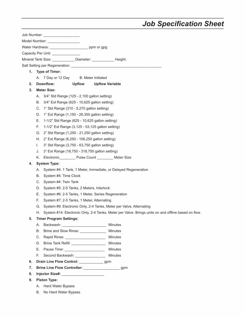
Job Specification Sheet
Job Number: __________________
Model Number: ________________
Water Hardness: ___________________ ppm or gpg
Capacity Per Unit: ______________
Mineral Tank Size: ___________ Diameter: ___________ Height:
Salt Setting per Regeneration: _____________________________________________
1. Type of Timer:
A. 7 Day or 12 Day B. Meter Initiated
2. Downflow: Upflow Upflow Variable
3. Meter Size:
A. 3/4” Std Range (125 - 2,100 gallon setting)
B. 3/4” Ext Range (625 - 10,625 gallon setting)
C. 1” Std Range (310 - 5,270 gallon setting)
D. 1” Ext Range (1,150 - 26,350 gallon setting)
E. 1-1/2” Std Range (625 - 10,625 gallon setting)
F. 1-1/2” Ext Range (3,125 - 53,125 gallon setting)
G. 2” Std Range (1,250 - 21,250 gallon setting)
H. 2” Ext Range (6,250 - 106,250 gallon setting)
I. 3” Std Range (3,750 - 63,750 gallon setting)
J. 3” Ext Range (18,750 - 318,750 gallon setting)
K. Electronic________ Pulse Count ________ Meter Size
4. System Type:
A. System #4: 1 Tank, 1 Meter, Immediate, or Delayed Regeneration
B. System #4: Time Clock
C. System #4: Twin Tank
D. System #5: 2-5 Tanks, 2 Meters, Interlock
E. System #6: 2-5 Tanks, 1 Meter, Series Regeneration
F. System #7: 2-5 Tanks, 1 Meter, Alternating
G. System #9: Electronic Only, 2-4 Tanks, Meter per Valve, Alternating
H. System #14: Electronic Only, 2-4 Tanks, Meter per Valve. Brings units on and offline based on flow.
5. Timer Program Settings:
A. Backwash: ______________________ Minutes
B. Brine and Slow Rinse: _____________ Minutes
C. Rapid Rinse: ____________________ Minutes
D. Brine Tank Refill: _________________ Minutes
E. Pause Time: ____________________ Minutes
F. Second Backwash: _______________ Minutes
6. Drain Line Flow Control: ____________ gpm
7. Brine Line Flow Controller: __________________ gpm
8. Injector Size#: _____________________
9. Piston Type:
A. Hard Water Bypass
B. No Hard Water Bypass
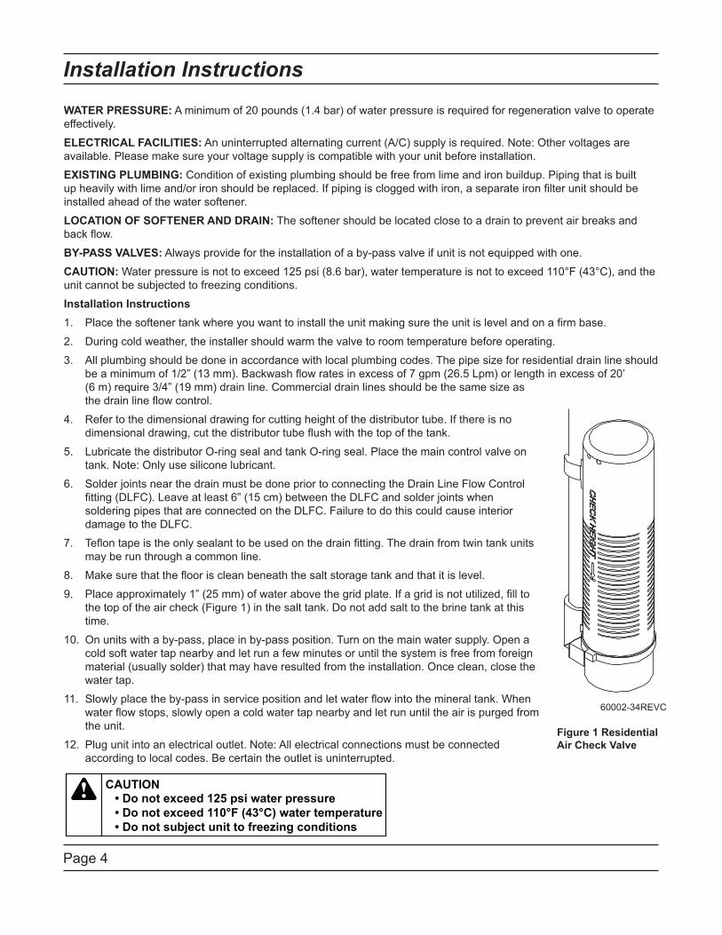
Installation Instructions
Page 4
WATER PRESSURE: A minimum of 20 pounds (1.4 bar) of water pressure is required for regeneration valve to operate
effectively.
ELECTRICAL FACILITIES: An uninterrupted alternating current (A/C) supply is required. Note: Other voltages are
available. Please make sure your voltage supply is compatible with your unit before installation.
EXISTING PLUMBING: Condition of existing plumbing should be free from lime and iron buildup. Piping that is built
up heavily with lime and/or iron should be replaced. If piping is clogged with iron, a separate iron filter unit should be
installed ahead of the water softener.
LOCATION OF SOFTENER AND DRAIN: The softener should be located close to a drain to prevent air breaks and
back flow.
BY-PASS VALVES: Always provide for the installation of a by-pass valve if unit is not equipped with one.
CAUTION: Water pressure is not to exceed 125 psi (8.6 bar), water temperature is not to exceed 110°F (43°C), and the
unit cannot be subjected to freezing conditions.
Installation Instructions
Place the softener tank where you want to install the unit making sure the unit is level and on a firm base.1.
During cold weather, the installer should warm the valve to room temperature before operating.2.
All plumbing should be done in accordance with local plumbing codes. The pipe size for residential drain line should 3.
be a minimum of 1/2” (13 mm). Backwash flow rates in excess of 7 gpm (26.5 Lpm) or length in excess of 20’
(6 m) require 3/4” (19 mm) drain line. Commercial drain lines should be the same size as
the drain line flow control.
Refer to the dimensional drawing for cutting height of the distributor tube. If there is no 4.
dimensional drawing, cut the distributor tube flush with the top of the tank.
Lubricate the distributor O-ring seal and tank O-ring seal. Place the main control valve on 5.
tank. Note: Only use silicone lubricant.
Solder joints near the drain must be done prior to connecting the Drain Line Flow Control 6.
fitting (DLFC). Leave at least 6” (15 cm) between the DLFC and solder joints when
soldering pipes that are connected on the DLFC. Failure to do this could cause interior
damage to the DLFC.
Teflon tape is the only sealant to be used on the drain fitting. The drain from twin tank units 7.
may be run through a common line.
Make sure that the floor is clean beneath the salt storage tank and that it is level.8.
Place approximately 1” (25 mm) of water above the grid plate. If a grid is not utilized, fill to 9.
the top of the air check (Figure 1) in the salt tank. Do not add salt to the brine tank at this
time.
On units with a by-pass, place in by-pass position. Turn on the main water supply. Open a 10.
cold soft water tap nearby and let run a few minutes or until the system is free from foreign
material (usually solder) that may have resulted from the installation. Once clean, close the
water tap.
Slowly place the by-pass in service position and let water flow into the mineral tank. When 11.
water flow stops, slowly open a cold water tap nearby and let run until the air is purged from
the unit.
Plug unit into an electrical outlet. Note: All electrical connections must be connected 12.
according to local codes. Be certain the outlet is uninterrupted.
60002-34REVC
Figure 1 Residential
Air Check Valve
Start-Up Instructions
Page 5
The water softener should be installed with the inlet, outlet, and drain connections made in accordance with the
manufacturer’s recommendations, and to meet applicable plumbing codes.
Turn the manual regeneraton knob slowly in a clockwise direction until the program micro switch lifts on top of 1.
the first set of pins. Allow the drive motor to move the piston to the first regeneration step and stop. Each time
the program switch position changes, the valve will advance to the next regeneration step. Always allow the
motor to stop before moving to the next set of pins or spaces.
NOTE: For electronic valves, please refer to the manual regeneration part of the timer operation
section. If the valve came with a separate electronic timer service manual, refer to the timer operation
section of the electronic timer service manual.
Position the valve to backwash. Ensure the drain line flow remains steady for 10 minutes or until the water 2.
runs clear (see above).
Position the valve to the brine / slow rinse position. Ensure the unit is drawing water from the brine tank (this 3.
step may need to be repeated).
Position the valve to the rapid rinse position. Check the drain line flow, and run for 5 minutes or until the water 4.
runs clear.
Position the valve to the start of the brine tank fill cycle. Ensure water goes into the brine tank at the desired 5.
rate. The brine valve drive cam will hold the valve in this position to fill the brine tank for the first regeneration.
Replace control box cover.6.
Put salt in the brine tank. 7.
NOTE: Do not use granulated or rock salt.
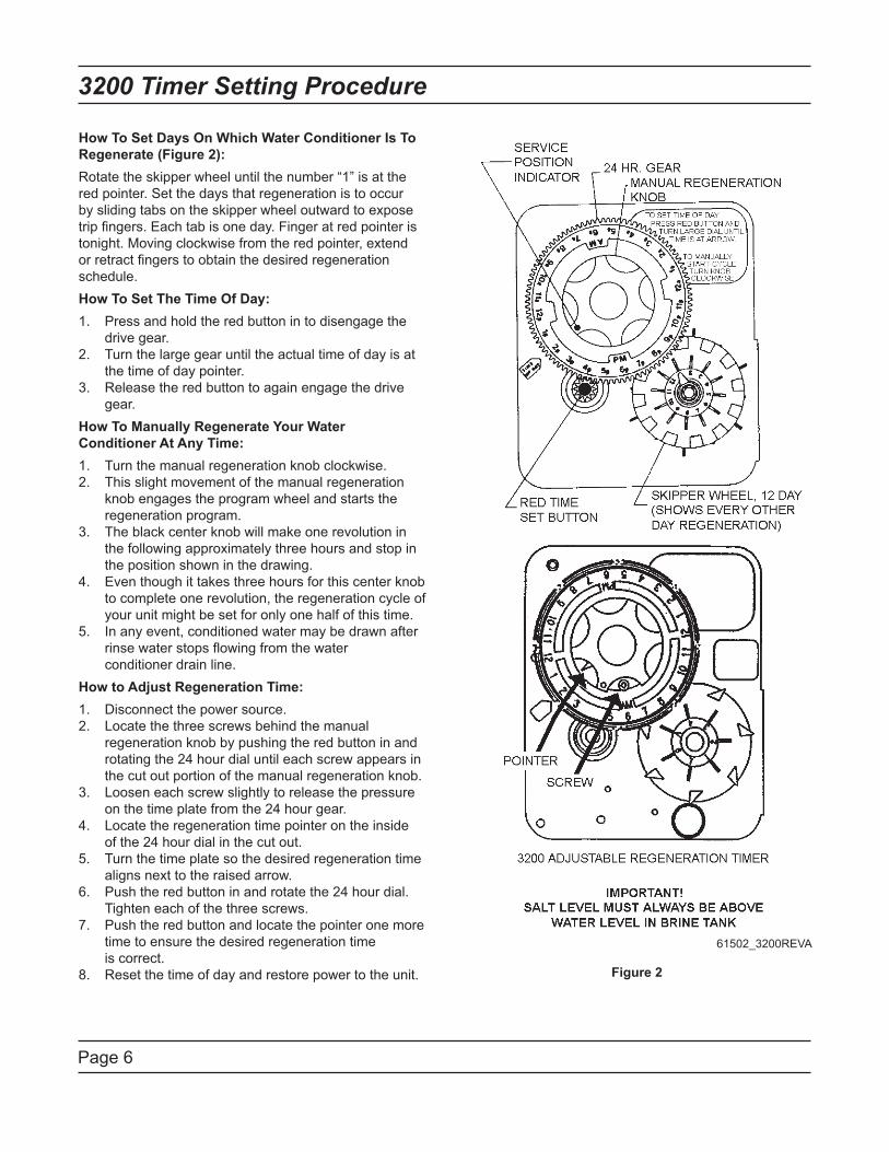
Page 6
3200 Timer Setting Procedure
How To Set Days On Which Water Conditioner Is To
Regenerate (Figure 2):
Rotate the skipper wheel until the number “1” is at the
red pointer. Set the days that regeneration is to occur
by sliding tabs on the skipper wheel outward to expose
trip fingers. Each tab is one day. Finger at red pointer is
tonight. Moving clockwise from the red pointer, extend
or retract fingers to obtain the desired regeneration
schedule.
How To Set The Time Of Day:
1. Press and hold the red button in to disengage the
drive gear.
2. Turn the large gear until the actual time of day is at
the time of day pointer.
3. Release the red button to again engage the drive
gear.
How To Manually Regenerate Your Water
Conditioner At Any Time:
1. Turn the manual regeneration knob clockwise.
2. This slight movement of the manual regeneration
knob engages the program wheel and starts the
regeneration program.
3. The black center knob will make one revolution in
the following approximately three hours and stop in
the position shown in the drawing.
4. Even though it takes three hours for this center knob
to complete one revolution, the regeneration cycle of
your unit might be set for only one half of this time.
5. In any event, conditioned water may be drawn after
rinse water stops flowing from the water
conditioner drain line.
How to Adjust Regeneration Time:
1. Disconnect the power source.
2. Locate the three screws behind the manual
regeneration knob by pushing the red button in and
rotating the 24 hour dial until each screw appears in
the cut out portion of the manual regeneration knob.
3. Loosen each screw slightly to release the pressure
on the time plate from the 24 hour gear.
4. Locate the regeneration time pointer on the inside
of the 24 hour dial in the cut out.
5. Turn the time plate so the desired regeneration time
aligns next to the raised arrow.
6. Push the red button in and rotate the 24 hour dial.
Tighten each of the three screws.
7. Push the red button and locate the pointer one more
time to ensure the desired regeneration time
is correct.
8. Reset the time of day and restore power to the unit. Figure 2
61502_3200REVA
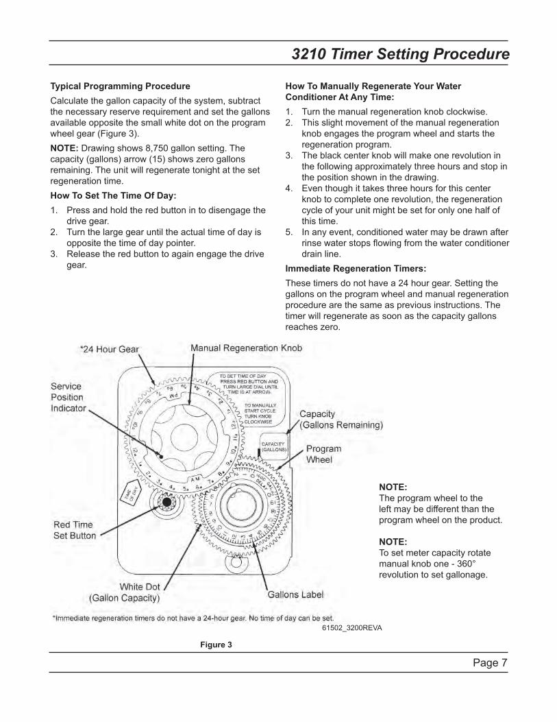
Page 7
3210 Timer Setting Procedure
Typical Programming Procedure
Calculate the gallon capacity of the system, subtract
the necessary reserve requirement and set the gallons
available opposite the small white dot on the program
wheel gear (Figure 3).
NOTE: Drawing shows 8,750 gallon setting. The
capacity (gallons) arrow (15) shows zero gallons
remaining. The unit will regenerate tonight at the set
regeneration time.
How To Set The Time Of Day:
Press and hold the red button in to disengage the 1.
drive gear.
Turn the large gear until the actual time of day is 2.
opposite the time of day pointer.
Release the red button to again engage the drive 3.
gear.
How To Manually Regenerate Your Water
Conditioner At Any Time:
Turn the manual regeneration knob clockwise.1.
This slight movement of the manual regeneration 2.
knob engages the program wheel and starts the
regeneration program.
The black center knob will make one revolution in 3.
the following approximately three hours and stop in
the position shown in the drawing.
Even though it takes three hours for this center 4.
knob to complete one revolution, the regeneration
cycle of your unit might be set for only one half of
this time.
In any event, conditioned water may be drawn after 5.
rinse water stops flowing from the water conditioner
drain line.
Immediate Regeneration Timers:
These timers do not have a 24 hour gear. Setting the
gallons on the program wheel and manual regeneration
procedure are the same as previous instructions. The
timer will regenerate as soon as the capacity gallons
reaches zero.
NOTE:
The program wheel to the
left may be different than the
program wheel on the product.
NOTE:
To set meter capacity rotate
manual knob one - 360°
revolution to set gallonage.
Figure 3
61502_3200REVA
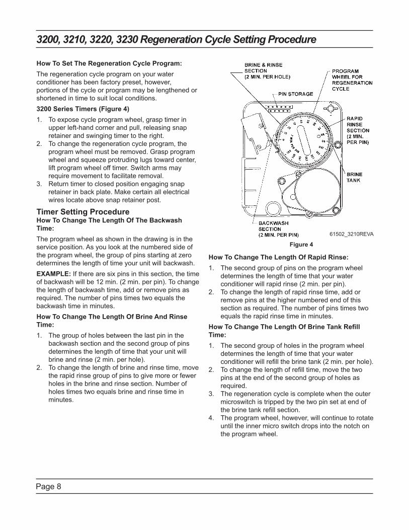
Page 8
3200, 3210, 3220, 3230 Regeneration Cycle Setting Procedure
How To Set The Regeneration Cycle Program:
The regeneration cycle program on your water
conditioner has been factory preset, however,
portions of the cycle or program may be lengthened or
shortened in time to suit local conditions.
3200 Series Timers (Figure 4)
To expose cycle program wheel, grasp timer in 1.
upper left-hand corner and pull, releasing snap
retainer and swinging timer to the right.
To change the regeneration cycle program, the 2.
program wheel must be removed. Grasp program
wheel and squeeze protruding lugs toward center,
lift program wheel off timer. Switch arms may
require movement to facilitate removal.
Return timer to closed position engaging snap 3.
retainer in back plate. Make certain all electrical
wires locate above snap retainer post.
Timer Setting Procedure How To Change The Length Of The Backwash
Time:
The program wheel as shown in the drawing is in the
service position. As you look at the numbered side of
the program wheel, the group of pins starting at zero
determines the length of time your unit will backwash.
EXAMPLE: If there are six pins in this section, the time
of backwash will be 12 min. (2 min. per pin). To change
the length of backwash time, add or remove pins as
required. The number of pins times two equals the
backwash time in minutes.
How To Change The Length Of Brine And Rinse
Time:
The group of holes between the last pin in the 1.
backwash section and the second group of pins
determines the length of time that your unit will
brine and rinse (2 min. per hole).
To change the length of brine and rinse time, move 2.
the rapid rinse group of pins to give more or fewer
holes in the brine and rinse section. Number of
holes times two equals brine and rinse time in
minutes.
How To Change The Length Of Rapid Rinse:
The second group of pins on the program wheel 1.
determines the length of time that your water
conditioner will rapid rinse (2 min. per pin).
To change the length of rapid rinse time, add or 2.
remove pins at the higher numbered end of this
section as required. The number of pins times two
equals the rapid rinse time in minutes.
How To Change The Length Of Brine Tank Refill
Time:
The second group of holes in the program wheel 1.
determines the length of time that your water
conditioner will refill the brine tank (2 min. per hole).
To change the length of refill time, move the two 2.
pins at the end of the second group of holes as
required.
The regeneration cycle is complete when the outer 3.
microswitch is tripped by the two pin set at end of
the brine tank refill section.
The program wheel, however, will continue to rotate 4.
until the inner micro switch drops into the notch on
the program wheel.
Figure 4
61502_3210REVA

Page 9
Notes
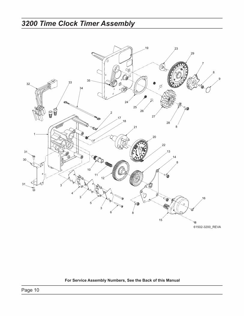
Page 10
3200 Time Clock Timer Assembly
61502-3200_REVA
For Service Assembly Numbers, See the Back of this Manual
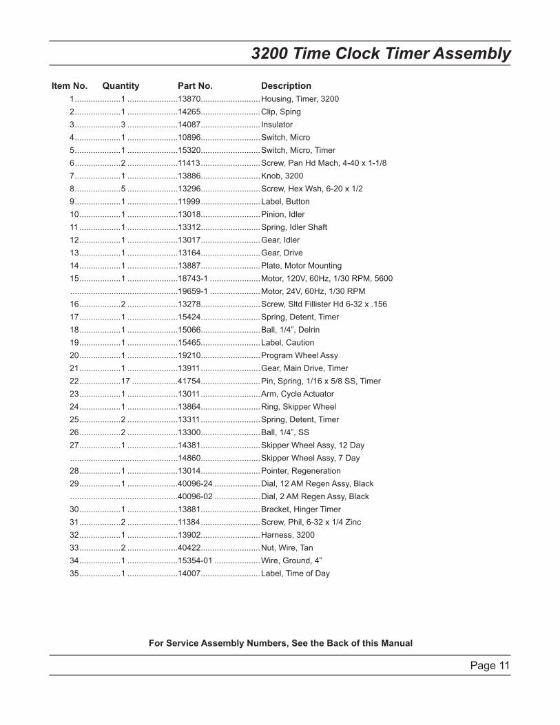
Page 11
3200 Time Clock Timer Assembly
Item No. Quantity Part No. Description
1 ....................1 ......................13870 ..........................Housing, Timer, 3200
2 ....................1 ......................14265 ..........................Clip, Sping
3 ....................3 ......................14087 .......................... Insulator
4 ....................1 ......................10896 ..........................Switch, Micro
5 ....................1 ......................15320 ..........................Switch, Micro, Timer
6 ....................2 ......................11413 ..........................Screw, Pan Hd Mach, 4-40 x 1-1/8
7 ....................1 ......................13886 ..........................Knob, 3200
8 ....................5 ......................13296 ..........................Screw, Hex Wsh, 6-20 x 1/2
9 ....................1 ......................11999 ..........................Label, Button
10 ..................1 ......................13018 ..........................Pinion, Idler
11 ..................1 ......................13312 ..........................Spring, Idler Shaft
12 ..................1 ......................13017 ..........................Gear, Idler
13 ..................1 ......................13164 ..........................Gear, Drive
14 ..................1 ......................13887 ..........................Plate, Motor Mounting
15 ..................1 ......................18743-1 ......................Motor, 120V, 60Hz, 1/30 RPM, 5600
...............................................19659-1 ......................Motor, 24V, 60Hz, 1/30 RPM
16 ..................2 ......................13278 ..........................Screw, Sltd Fillister Hd 6-32 x .156
17 ..................1 ......................15424 ..........................Spring, Detent, Timer
18 ..................1 ......................15066 ..........................Ball, 1/4”, Delrin
19 ..................1 ......................15465 ..........................Label, Caution
20 ..................1 ......................19210 ..........................Program Wheel Assy
21 ..................1 ......................13911 ..........................Gear, Main Drive, Timer
22 ..................17 ....................41754 ..........................Pin, Spring, 1/16 x 5/8 SS, Timer
23 ..................1 ......................13011 ..........................Arm, Cycle Actuator
24 ..................1 ......................13864 ..........................Ring, Skipper Wheel
25 ..................2 ......................13311 ..........................Spring, Detent, Timer
26 ..................2 ......................13300 ..........................Ball, 1/4”, SS
27 ..................1 ......................14381 ..........................Skipper Wheel Assy, 12 Day
...............................................14860 ..........................Skipper Wheel Assy, 7 Day
28 ..................1 ......................13014 ..........................Pointer, Regeneration
29 ..................1 ......................40096-24 ....................Dial, 12 AM Regen Assy, Black
...............................................40096-02 ....................Dial, 2 AM Regen Assy, Black
30 ..................1 ......................13881 ..........................Bracket, Hinger Timer
31 ..................2 ......................11384 ..........................Screw, Phil, 6-32 x 1/4 Zinc
32 ..................1 ......................13902 ..........................Harness, 3200
33 ..................2 ......................40422 ..........................Nut, Wire, Tan
34 ..................1 ......................15354-01 ....................Wire, Ground, 4”
35 ..................1 ......................14007 ..........................Label, Time of Day
For Service Assembly Numbers, See the Back of this Manual
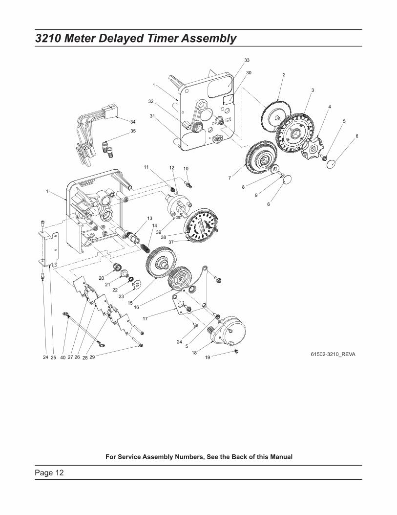
3210 Meter Delayed Timer Assembly
Page 12
61502-3210_REVA
For Service Assembly Numbers, See the Back of this Manual
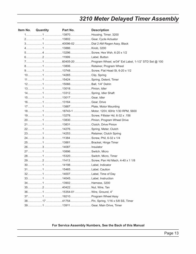
3210 Meter Delayed Timer Assembly
Page 13
Item No. Quantity Part No. Description
1 ....................1 ......................13870 ..........................Housing, Timer, 3200
2 ....................1 ......................13802 ..........................Gear, Cycle Actuator
3 ....................1 ......................40096-02 ....................Dial 2 AM Regen Assy, Black
4 ....................1 ......................13886 ..........................Knob, 3200
5 ....................4 ......................13296 ..........................Screw, Hex Wsh, 6-20 x 1/2
6 ....................2 ......................11999 ..........................Label, Button
7 ....................1 ......................60405-20 ....................Program Wheel, w/34” Ext Label, 1-1/2” STD Set @ 100
8 ....................1 ......................13806 ..........................Retainer, Program Wheel
9 ....................1 ......................13748 ..........................Screw, Flat Head St, 6-20 x 1/2
10 ..................1 ......................14265 ..........................Clip, Spring
11 ..................1 ......................15424 ..........................Spring, Detent, Timer
12 ..................1 ......................15066 ..........................Ball, 1/4” Delrin
13 ..................1 ......................13018 ..........................Pinion, Idler
14 ..................1 ......................13312 ..........................Spring, Idler Shaft
15 ..................1 ......................13017 ..........................Gear, Idler
16 ..................1 ......................13164 ..........................Gear, Drive
17 ..................1 ......................13887 ..........................Plate, Motor Mounting
18 ..................1 ......................18743-1 ......................Motor, 120V, 60Hz 1/30 RPM, 5600
19 ..................1 ......................13278 ..........................Screw, Fillister Hd, 6-32 x .156
20 ..................1 ......................13830 ..........................Pinion, Program Wheel Drive
21 ..................1 ......................13831 ..........................Clutch, Drive Pinion
22 ..................1 ......................14276 ..........................Spring, Meter, Clutch
23 ..................1 ......................14253 ..........................Retainer, Clutch Spring
24 ..................3 ......................11384 ..........................Screw, Phil, 6-32 x 1/4
25 ..................1 ......................13881 ..........................Bracket, Hinge Timer
26 ..................3 ......................14087 .......................... Insulator
27 ..................1 ......................10896 ..........................Switch, Micro
28 ..................1 ......................15320 ..........................Switch, Micro, Timer
29 ..................2 ......................11413 ..........................Screw, Pan Hd Mach, 4-40 x 1 1/8
30 ..................1 ......................14198 ..........................Label, Indicator
31 ..................1 ......................15465 ..........................Label, Caution
32 ..................1 ......................14007 ..........................Label, Time of Day
33 ..................1 ......................14045 ..........................Label, Instruction
34 ..................1 ......................13902 ..........................Harness, 3200
35 ..................2 ......................40422 ..........................Nut, Wire, Tan
36 ..................1 ......................15354-01 ....................Wire, Ground, 4”
37 ..................1 ......................19210 ..........................Program Wheel Assy
38 ..................17 ....................41754 ..........................Pin, Spring, 1/16 x 5/8 SS, Timer
39 ..................1 ......................13911 ..........................Gear, Main Drive, Timer
For Service Assembly Numbers, See the Back of this Manual
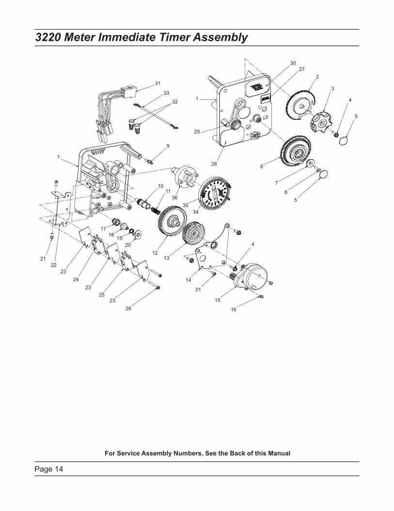
Page 14
3220 Meter Immediate Timer Assembly
1
2
3
4
5
6
7
8
9
1011
1213
14
15
16
1718
19
20
21
22
23
24
25
26
27
28
29
30
31
32
33
34
35
365
1
23
23
21
4
For Service Assembly Numbers, See the Back of this Manual
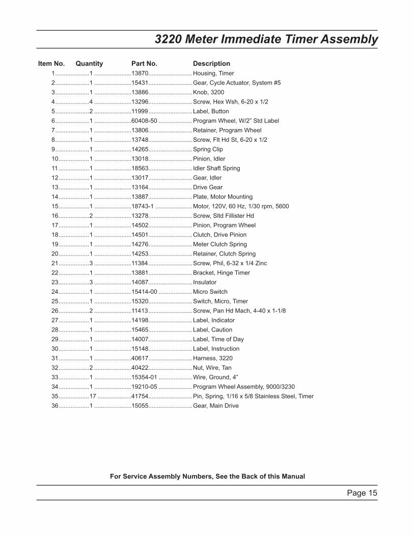
Page 15
3220 Meter Immediate Timer Assembly
Item No. Quantity Part No. Description
1 ....................1 ......................13870 ..........................Housing, Timer
2 ....................1 ......................15431 ..........................Gear, Cycle Actuator, System #5
3 ....................1 ......................13886 ..........................Knob, 3200
4 ....................4 ......................13296 ..........................Screw, Hex Wsh, 6-20 x 1/2
5 ....................2 ......................11999 ..........................Label, Button
6 ....................1 ......................60408-50 ....................Program Wheel, W/2” Std Label
7 ....................1 ......................13806 ..........................Retainer, Program Wheel
8 ....................1 ......................13748 ..........................Screw, Flt Hd St, 6-20 x 1/2
9 ....................1 ......................14265 ..........................Spring Clip
10 ..................1 ......................13018 ..........................Pinion, Idler
11 ..................1 ......................18563 .......................... Idler Shaft Spring
12 ..................1 ......................13017 ..........................Gear, Idler
13 ..................1 ......................13164 ..........................Drive Gear
14 ..................1 ......................13887 ..........................Plate, Motor Mounting
15 ..................1 ......................18743-1 ......................Motor, 120V, 60 Hz, 1/30 rpm, 5600
16 ..................2 ......................13278 ..........................Screw, Sltd Fillister Hd
17 ..................1 ......................14502 ..........................Pinion, Program Wheel
18 ..................1 ......................14501 ..........................Clutch, Drive Pinion
19 ..................1 ......................14276 ..........................Meter Clutch Spring
20 ..................1 ......................14253 ..........................Retainer, Clutch Spring
21 ..................3 ......................11384 ..........................Screw, Phil, 6-32 x 1/4 Zinc
22 ..................1 ......................13881 ..........................Bracket, Hinge Timer
23 ..................3 ......................14087 .......................... Insulator
24 ..................1 ......................15414-00 ....................Micro Switch
25 ..................1 ......................15320 ..........................Switch, Micro, Timer
26 ..................2 ......................11413 ..........................Screw, Pan Hd Mach, 4-40 x 1-1/8
27 ..................1 ......................14198 ..........................Label, Indicator
28 ..................1 ......................15465 ..........................Label, Caution
29 ..................1 ......................14007 ..........................Label, Time of Day
30 ..................1 ......................15148 ..........................Label, Instruction
31 ..................1 ......................40617 ..........................Harness, 3220
32 ..................2 ......................40422 ..........................Nut, Wire, Tan
33 ..................1 ......................15354-01 ....................Wire, Ground, 4”
34 ..................1 ......................19210-05 ....................Program Wheel Assembly, 9000/3230
35 ..................17 ....................41754 ..........................Pin, Spring, 1/16 x 5/8 Stainless Steel, Timer
36 ..................1 ......................15055 ..........................Gear, Main Drive
For Service Assembly Numbers, See the Back of this Manual
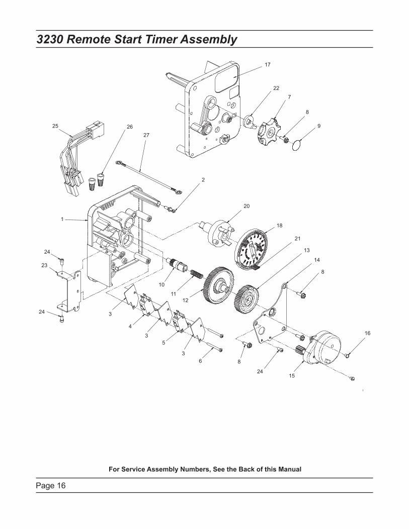
Page 16
3230 Remote Start Timer Assembly
1
2
3
4
5
6
7
8
9
10
11
12
13
14
15
16
17
18
20
8
8
3
3
24
24
24
23
21
25 26
27
22
For Service Assembly Numbers, See the Back of this Manual
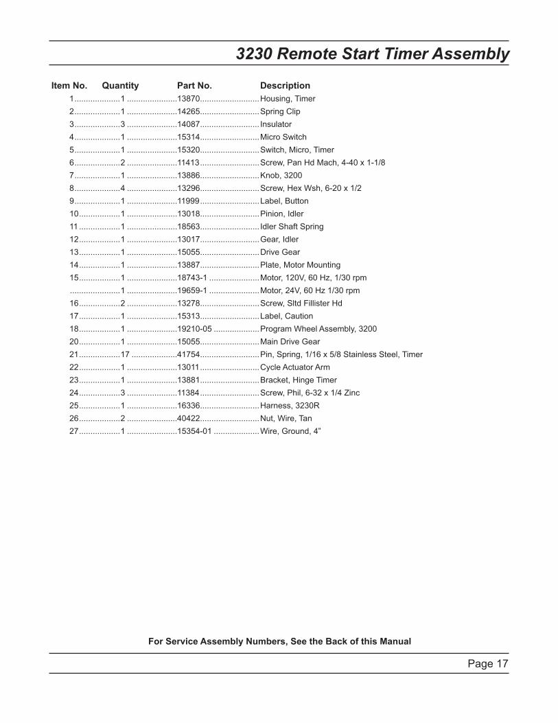
Page 17
3230 Remote Start Timer Assembly
Item No. Quantity Part No. Description
1 ....................1 ......................13870 ..........................Housing, Timer
2 ....................1 ......................14265 ..........................Spring Clip
3 ....................3 ......................14087 .......................... Insulator
4 ....................1 ......................15314 ..........................Micro Switch
5 ....................1 ......................15320 ..........................Switch, Micro, Timer
6 ....................2 ......................11413 ..........................Screw, Pan Hd Mach, 4-40 x 1-1/8
7 ....................1 ......................13886 ..........................Knob, 3200
8 ....................4 ......................13296 ..........................Screw, Hex Wsh, 6-20 x 1/2
9 ....................1 ......................11999 ..........................Label, Button
10 ..................1 ......................13018 ..........................Pinion, Idler
11 ..................1 ......................18563 .......................... Idler Shaft Spring
12 ..................1 ......................13017 ..........................Gear, Idler
13 ..................1 ......................15055 ..........................Drive Gear
14 ..................1 ......................13887 ..........................Plate, Motor Mounting
15 ..................1 ......................18743-1 ......................Motor, 120V, 60 Hz, 1/30 rpm
......................1 ......................19659-1 ......................Motor, 24V, 60 Hz 1/30 rpm
16 ..................2 ......................13278 ..........................Screw, Sltd Fillister Hd
17 ..................1 ......................15313 ..........................Label, Caution
18 ..................1 ......................19210-05 ....................Program Wheel Assembly, 3200
20 ..................1 ......................15055 ..........................Main Drive Gear
21 ..................17 ....................41754 ..........................Pin, Spring, 1/16 x 5/8 Stainless Steel, Timer
22 ..................1 ......................13011 ..........................Cycle Actuator Arm
23 ..................1 ......................13881 ..........................Bracket, Hinge Timer
24 ..................3 ......................11384 ..........................Screw, Phil, 6-32 x 1/4 Zinc
25 ..................1 ......................16336 ..........................Harness, 3230R
26 ..................2 ......................40422 ..........................Nut, Wire, Tan
27 ..................1 ......................15354-01 ....................Wire, Ground, 4”
For Service Assembly Numbers, See the Back of this Manual
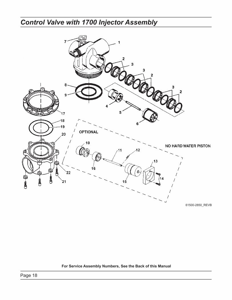
Control Valve with 1700 Injector Assembly
Page 18
61500-2850_REVB
For Service Assembly Numbers, See the Back of this Manual
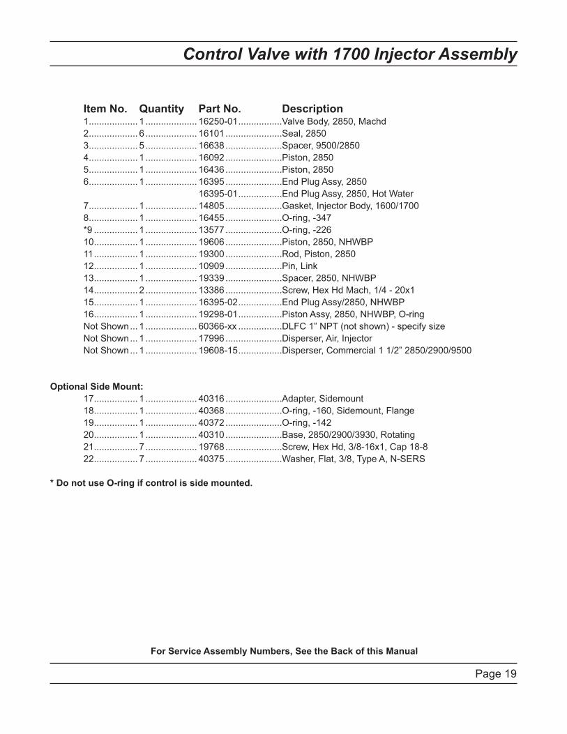
Control Valve with 1700 Injector Assembly
Page 19
Item No. Quantity Part No. Description 1 ................... 1 .................... 16250-01 .................Valve Body, 2850, Machd
2 ................... 6 .................... 16101 ......................Seal, 2850
3 ................... 5 .................... 16638 ......................Spacer, 9500/2850
4 ................... 1 .................... 16092 ......................Piston, 2850
5 ................... 1 .................... 16436 ......................Piston, 2850
6 ................... 1 .................... 16395 ......................End Plug Assy, 2850
16395-01 .................End Plug Assy, 2850, Hot Water
7 ................... 1 .................... 14805 ......................Gasket, Injector Body, 1600/1700
8 ................... 1 .................... 16455 ......................O-ring, -347
*9 ................. 1 .................... 13577 ......................O-ring, -226
10 ................. 1 .................... 19606 ......................Piston, 2850, NHWBP
11 ................. 1 .................... 19300 ......................Rod, Piston, 2850
12 ................. 1 .................... 10909 ......................Pin, Link
13 ................. 1 .................... 19339 ......................Spacer, 2850, NHWBP
14 ................. 2 .................... 13386 ......................Screw, Hex Hd Mach, 1/4 - 20x1
15 ................. 1 .................... 16395-02 .................End Plug Assy/2850, NHWBP
16 ................. 1 .................... 19298-01 .................Piston Assy, 2850, NHWBP, O-ring
Not Shown ... 1 .................... 60366-xx .................DLFC 1” NPT (not shown) - specify size
Not Shown ... 1 .................... 17996 ......................Disperser, Air, Injector
Not Shown ... 1 .................... 19608-15 .................Disperser, Commercial 1 1/2” 2850/2900/9500
Optional Side Mount:
17 ................. 1 .................... 40316 ......................Adapter, Sidemount
18 ................. 1 .................... 40368 ......................O-ring, -160, Sidemount, Flange
19 ................. 1 .................... 40372 ......................O-ring, -142
20 ................. 1 .................... 40310 ......................Base, 2850/2900/3930, Rotating
21 ................. 7 .................... 19768 ......................Screw, Hex Hd, 3/8-16x1, Cap 18-8
22 ................. 7 .................... 40375 ......................Washer, Flat, 3/8, Type A, N-SERS
* Do not use O-ring if control is side mounted.
For Service Assembly Numbers, See the Back of this Manual
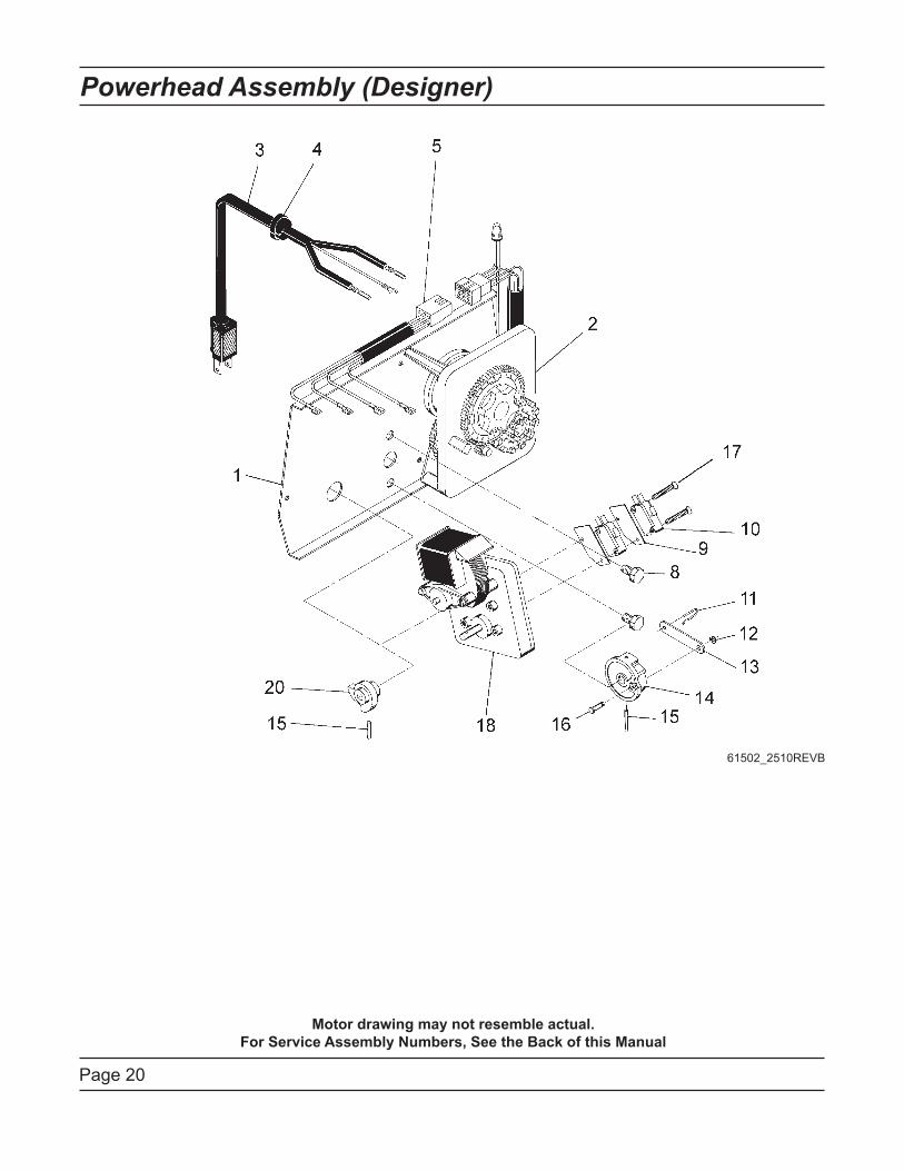
Page 20
Powerhead Assembly (Designer)
Motor drawing may not resemble actual.
For Service Assembly Numbers, See the Back of this Manual
61502_2510REVB
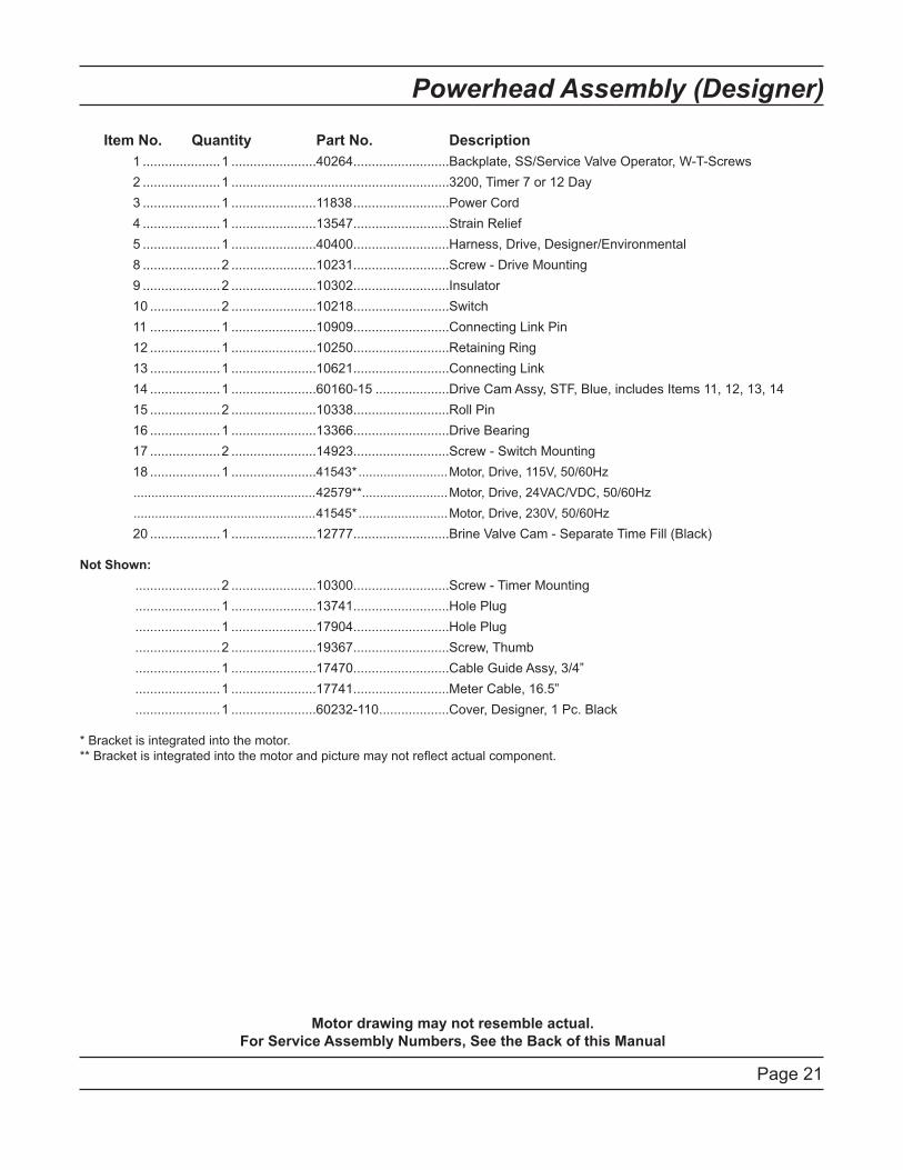
Page 21
Powerhead Assembly (Designer)
Item No. Quantity Part No. Description
1 .....................1 .......................40264 ..........................Backplate, SS/Service Valve Operator, W-T-Screws
2 .....................1 ...........................................................3200, Timer 7 or 12 Day
3 .....................1 .......................11838 ..........................Power Cord
4 .....................1 .......................13547 ..........................Strain Relief
5 .....................1 .......................40400 ..........................Harness, Drive, Designer/Environmental
8 .....................2 .......................10231 ..........................Screw - Drive Mounting
9 .....................2 .......................10302 ..........................Insulator
10 ...................2 .......................10218 ..........................Switch
11 ...................1 .......................10909 ..........................Connecting Link Pin
12 ...................1 .......................10250 ..........................Retaining Ring
13 ...................1 .......................10621 ..........................Connecting Link
14 ...................1 .......................60160-15 ....................Drive Cam Assy, STF, Blue, includes Items 11, 12, 13, 14
15 ...................2 .......................10338 ..........................Roll Pin
16 ...................1 .......................13366 ..........................Drive Bearing
17 ...................2 .......................14923 ..........................Screw - Switch Mounting
18 ...................1 .......................41543* .........................Motor, Drive, 115V, 50/60Hz
...................................................42579**........................Motor, Drive, 24VAC/VDC, 50/60Hz
...................................................41545* .........................Motor, Drive, 230V, 50/60Hz
20 ...................1 .......................12777 ..........................Brine Valve Cam - Separate Time Fill (Black)
Not Shown:
.......................2 .......................10300 ..........................Screw - Timer Mounting
.......................1 .......................13741 ..........................Hole Plug
.......................1 .......................17904 ..........................Hole Plug
.......................2 .......................19367 ..........................Screw, Thumb
.......................1 .......................17470 ..........................Cable Guide Assy, 3/4”
.......................1 .......................17741 ..........................Meter Cable, 16.5”
.......................1 .......................60232-110 ...................Cover, Designer, 1 Pc. Black
* Bracket is integrated into the motor.
** Bracket is integrated into the motor and picture may not reflect actual component.
Motor drawing may not resemble actual.
For Service Assembly Numbers, See the Back of this Manual
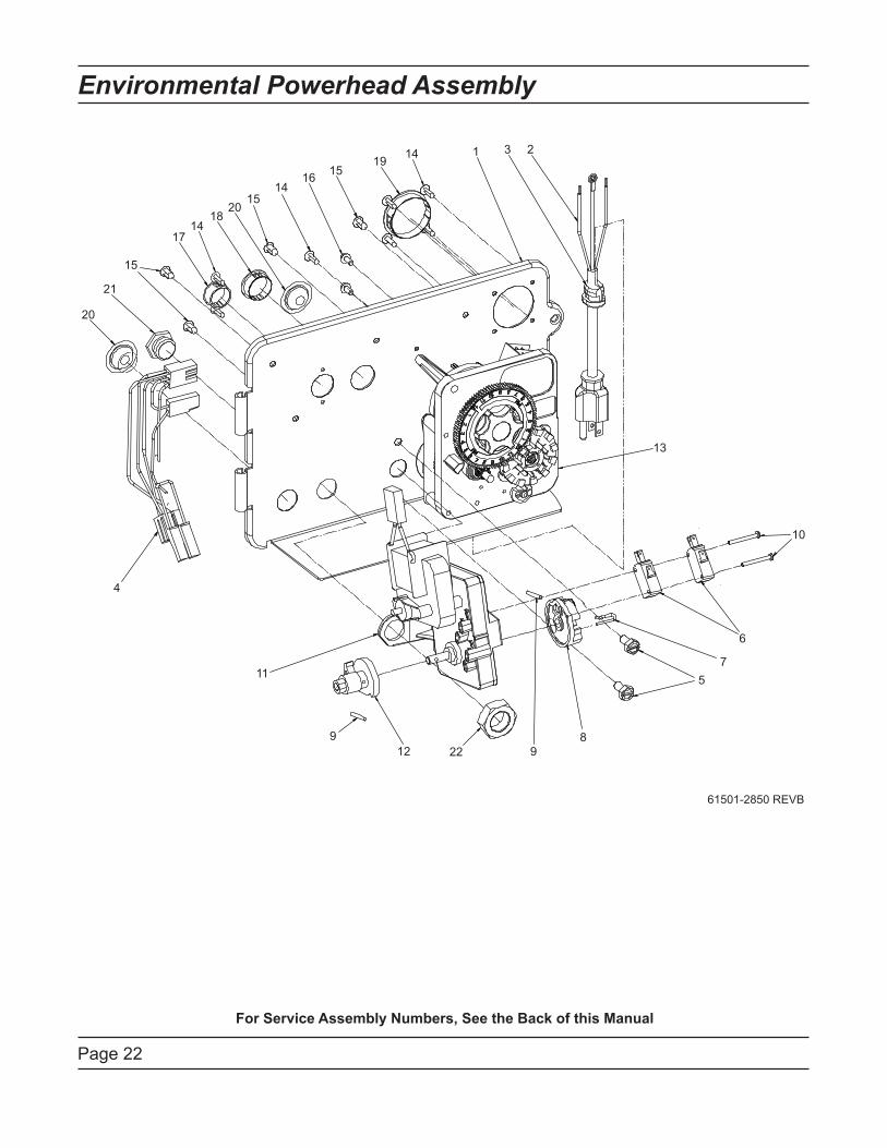
Page 22
Environmental Powerhead Assembly
61501-2850 REVB
1 23
4
5
6
7
8
9
10
11
12
13
14
15
16
17
18
19
20
21
22
9
2015
14
15
14
For Service Assembly Numbers, See the Back of this Manual
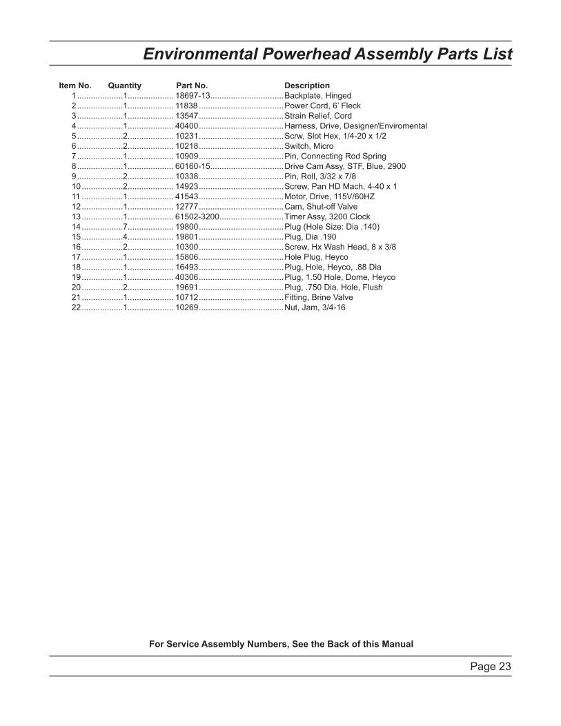
Page 23
Environmental Powerhead Assembly Parts List
Item No. Quantity Part No. Description
1 ....................1 .................... 18697-13................................Backplate, Hinged
2 ....................1 .................... 11838 .....................................Power Cord, 6’ Fleck
3 ....................1 .................... 13547 .....................................Strain Relief, Cord
4 ....................1 .................... 40400 .....................................Harness, Drive, Designer/Enviromental
5 ....................2 .................... 10231 .....................................Scrw, Slot Hex, 1/4-20 x 1/2
6 ....................2 .................... 10218 .....................................Switch, Micro
7 ....................1 .................... 10909 .....................................Pin, Connecting Rod Spring
8 ....................1 .................... 60160-15................................Drive Cam Assy, STF, Blue, 2900
9 ....................2 .................... 10338 .....................................Pin, Roll, 3/32 x 7/8
10 ..................2 .................... 14923 .....................................Screw, Pan HD Mach, 4-40 x 1
11 ..................1 .................... 41543 .....................................Motor, Drive, 115V/60HZ
12 ..................1 .................... 12777 .....................................Cam, Shut-off Valve
13 ..................1 .................... 61502-3200............................Timer Assy, 3200 Clock
14 ..................7 .................... 19800 .....................................Plug (Hole Size: Dia .140)
15 ..................4 .................... 19801 .....................................Plug, Dia .190
16 ..................2 .................... 10300 .....................................Screw, Hx Wash Head, 8 x 3/8
17 ..................1 .................... 15806 .....................................Hole Plug, Heyco
18 ..................1 .................... 16493 .....................................Plug, Hole, Heyco, .88 Dia
19 ..................1 .................... 40306 .....................................Plug, 1.50 Hole, Dome, Heyco
20 ..................2 .................... 19691 .....................................Plug, .750 Dia. Hole, Flush
21 ..................1 .................... 10712 .....................................Fitting, Brine Valve
22 ..................1 .................... 10269 .....................................Nut, Jam, 3/4-16
For Service Assembly Numbers, See the Back of this Manual
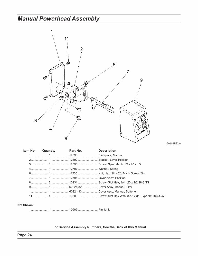
Page 24
Manual Powerhead Assembly
Item No. Quantity Part No. Description
1 ..................... 1 .......................12593 ..........................Backplate, Manual
2 ..................... 1 .......................12592 ..........................Bracket, Lever Position
3 ..................... 1 .......................12596 ..........................Screw, Spec Mach, 1/4 - 20 x 1/2
4 ..................... 1 .......................12707 ..........................Washer, Spring
6 ..................... 1 .......................11235 ..........................Nut, Hex, 1/4 - 20, Mach Screw, Zinc
7 ..................... 1 .......................12594 ..........................Lever, Valve Position
8 ..................... 2 .......................10231 ..........................Screw, Slot Hex, 1/4 - 20 x 1/2 18-8 SS
9 ..................... 1 .......................60224-32 ....................Cover Assy, Manual, Filter
....................... 1 .......................60224-33 ....................Cover Assy, Manual, Softener
11 ................... 4 .......................10300 ..........................Screw, Slot Hex Wsh, 8-18 x 3/8 Type “B” RC44-47
Not Shown:
....................... 1 .......................10909 ..........................Pin, Link
60409REVA
For Service Assembly Numbers, See the Back of this Manual
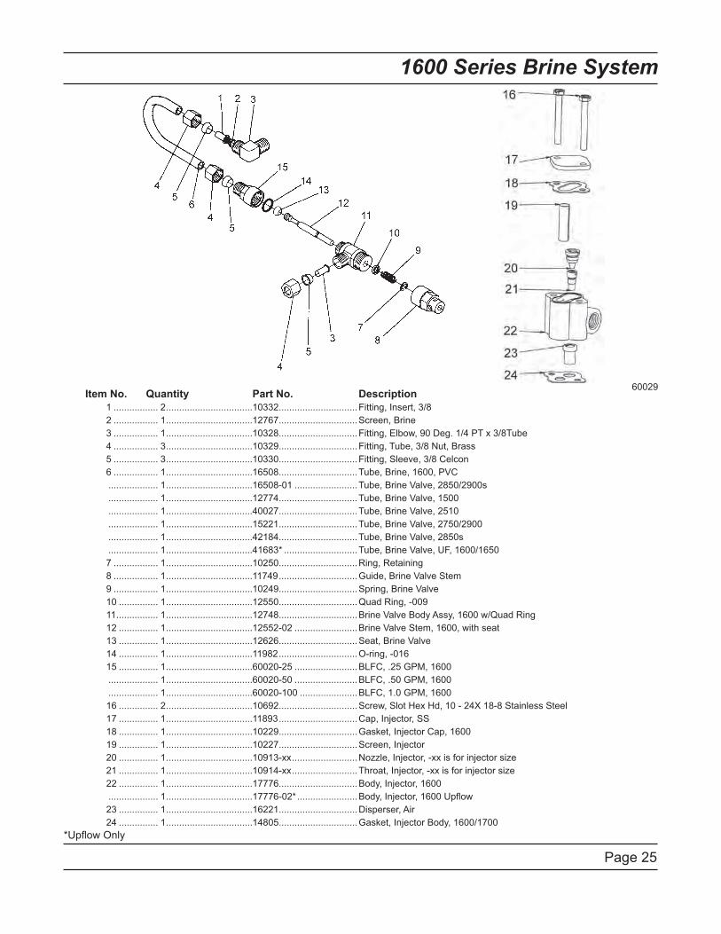
Page 25
1600 Series Brine System
Item No. Quantity Part No. Description
1 ................. 2 .................................10332 ..............................Fitting, Insert, 3/8
2 ................. 1 .................................12767 ..............................Screen, Brine
3 ................. 1 .................................10328 ..............................Fitting, Elbow, 90 Deg. 1/4 PT x 3/8Tube
4 ................. 3 .................................10329 ..............................Fitting, Tube, 3/8 Nut, Brass
5 ................. 3 .................................10330 ..............................Fitting, Sleeve, 3/8 Celcon
6 ................. 1 .................................16508 ..............................Tube, Brine, 1600, PVC
................... 1 .................................16508-01 ........................Tube, Brine Valve, 2850/2900s
................... 1 .................................12774 ..............................Tube, Brine Valve, 1500
................... 1 .................................40027 ..............................Tube, Brine Valve, 2510
................... 1 .................................15221 ..............................Tube, Brine Valve, 2750/2900
................... 1 .................................42184 ..............................Tube, Brine Valve, 2850s
................... 1 .................................41683* ............................Tube, Brine Valve, UF, 1600/1650
7 ................. 1 .................................10250 ..............................Ring, Retaining
8 ................. 1 .................................11749 ..............................Guide, Brine Valve Stem
9 ................. 1 .................................10249 ..............................Spring, Brine Valve
10 ............... 1 .................................12550 ..............................Quad Ring, -009
11 ................ 1 .................................12748 ..............................Brine Valve Body Assy, 1600 w/Quad Ring
12 ............... 1 .................................12552-02 ........................Brine Valve Stem, 1600, with seat
13 ............... 1 .................................12626 ..............................Seat, Brine Valve
14 ............... 1 .................................11982 ..............................O-ring, -016
15 ............... 1 .................................60020-25 ........................BLFC, .25 GPM, 1600
................... 1 .................................60020-50 ........................BLFC, .50 GPM, 1600
................... 1 .................................60020-100 ......................BLFC, 1.0 GPM, 1600
16 ............... 2 .................................10692 ..............................Screw, Slot Hex Hd, 10 - 24X 18-8 Stainless Steel
17 ............... 1 .................................11893 ..............................Cap, Injector, SS
18 ............... 1 .................................10229 ..............................Gasket, Injector Cap, 1600
19 ............... 1 .................................10227 ..............................Screen, Injector
20 ............... 1 .................................10913-xx .........................Nozzle, Injector, -xx is for injector size
21 ............... 1 .................................10914-xx .........................Throat, Injector, -xx is for injector size
22 ............... 1 .................................17776 ..............................Body, Injector, 1600
................... 1 .................................17776-02* .......................Body, Injector, 1600 Upflow
23 ............... 1 .................................16221 ..............................Disperser, Air
24 ............... 1 .................................14805 ..............................Gasket, Injector Body, 1600/1700
*Upflow Only
60029
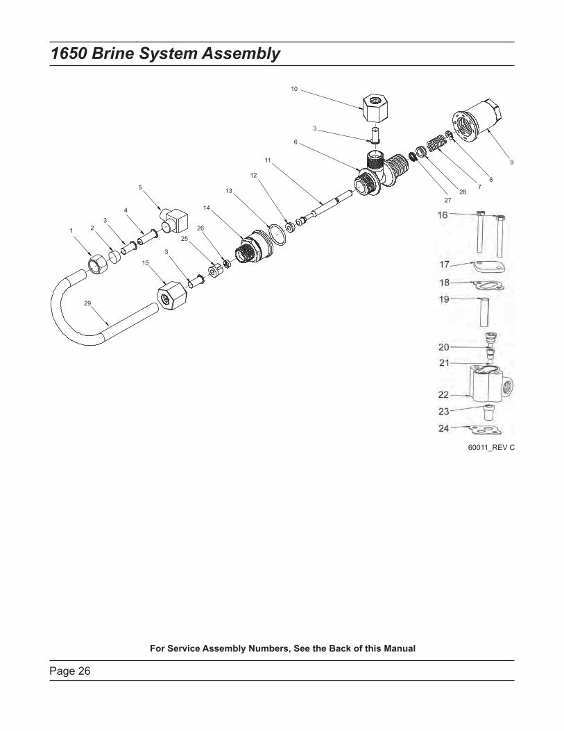
Page 26
1650 Brine System Assembly
1 2
3
4
5
6
7
8
9
10
11
12
13
14
15
29
25
26
27
28
3
3
60011_REV C
For Service Assembly Numbers, See the Back of this Manual
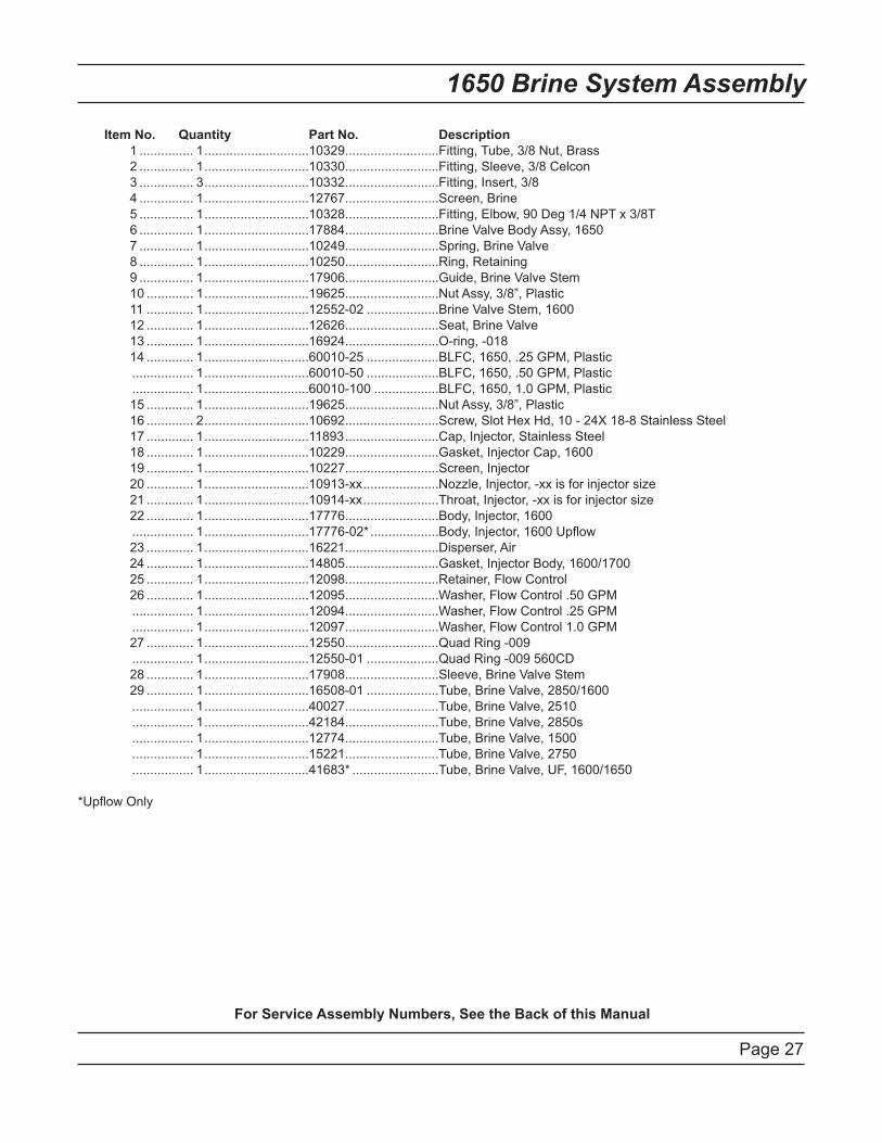
Page 27
Item No. Quantity Part No. Description
1 ............... 1 .............................10329 ..........................Fitting, Tube, 3/8 Nut, Brass
2 ............... 1 .............................10330 ..........................Fitting, Sleeve, 3/8 Celcon
3 ............... 3 .............................10332 ..........................Fitting, Insert, 3/8
4 ............... 1 .............................12767 ..........................Screen, Brine
5 ............... 1 .............................10328 ..........................Fitting, Elbow, 90 Deg 1/4 NPT x 3/8T
6 ............... 1 .............................17884 ..........................Brine Valve Body Assy, 1650
7 ............... 1 .............................10249 ..........................Spring, Brine Valve
8 ............... 1 .............................10250 ..........................Ring, Retaining
9 ............... 1 .............................17906 ..........................Guide, Brine Valve Stem
10 ............. 1 .............................19625 ..........................Nut Assy, 3/8”, Plastic
11 ............. 1 .............................12552-02 ....................Brine Valve Stem, 1600
12 ............. 1 .............................12626 ..........................Seat, Brine Valve
13 ............. 1 .............................16924 ..........................O-ring, -018
14 ............. 1 .............................60010-25 ....................BLFC, 1650, .25 GPM, Plastic
................. 1 .............................60010-50 ....................BLFC, 1650, .50 GPM, Plastic
................. 1 .............................60010-100 ..................BLFC, 1650, 1.0 GPM, Plastic
15 ............. 1 .............................19625 ..........................Nut Assy, 3/8”, Plastic
16 ............. 2 .............................10692 ..........................Screw, Slot Hex Hd, 10 - 24X 18-8 Stainless Steel
17 ............. 1 .............................11893 ..........................Cap, Injector, Stainless Steel
18 ............. 1 .............................10229 ..........................Gasket, Injector Cap, 1600
19 ............. 1 .............................10227 ..........................Screen, Injector
20 ............. 1 .............................10913-xx .....................Nozzle, Injector, -xx is for injector size
21 ............. 1 .............................10914-xx .....................Throat, Injector, -xx is for injector size
22 ............. 1 .............................17776 ..........................Body, Injector, 1600
................. 1 .............................17776-02* ...................Body, Injector, 1600 Upflow
23 ............. 1 .............................16221 ..........................Disperser, Air
24 ............. 1 .............................14805 ..........................Gasket, Injector Body, 1600/1700
25 ............. 1 .............................12098 ..........................Retainer, Flow Control
26 ............. 1 .............................12095 ..........................Washer, Flow Control .50 GPM
................. 1 .............................12094 ..........................Washer, Flow Control .25 GPM
................. 1 .............................12097 ..........................Washer, Flow Control 1.0 GPM
27 ............. 1 .............................12550 ..........................Quad Ring -009
................. 1 .............................12550-01 ....................Quad Ring -009 560CD
28 ............. 1 .............................17908 ..........................Sleeve, Brine Valve Stem
29 ............. 1 .............................16508-01 ....................Tube, Brine Valve, 2850/1600
................. 1 .............................40027 ..........................Tube, Brine Valve, 2510
................. 1 .............................42184 ..........................Tube, Brine Valve, 2850s
................. 1 .............................12774 ..........................Tube, Brine Valve, 1500
................. 1 .............................15221 ..........................Tube, Brine Valve, 2750
................. 1 .............................41683* ........................Tube, Brine Valve, UF, 1600/1650
*Upflow Only
1650 Brine System Assembly
For Service Assembly Numbers, See the Back of this Manual
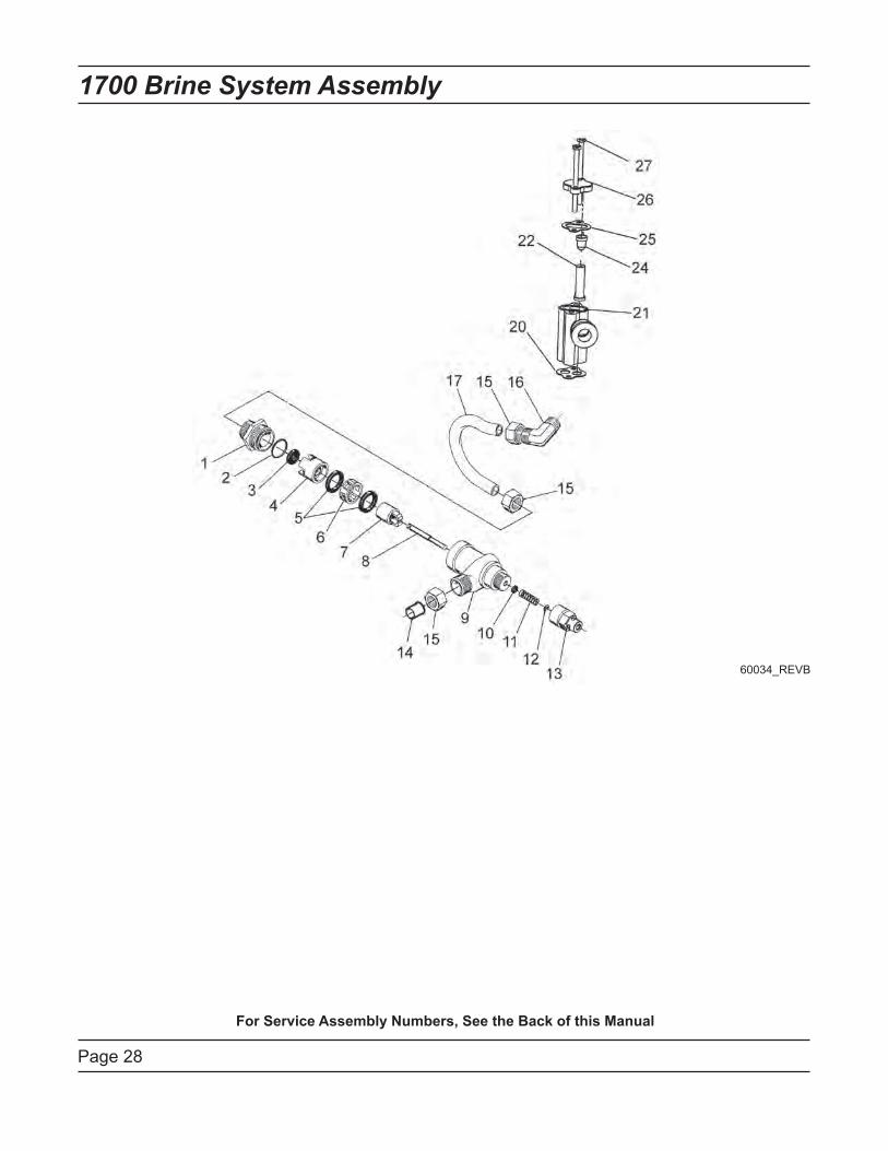
Page 28
1700 Brine System Assembly
For Service Assembly Numbers, See the Back of this Manual
60034_REVB
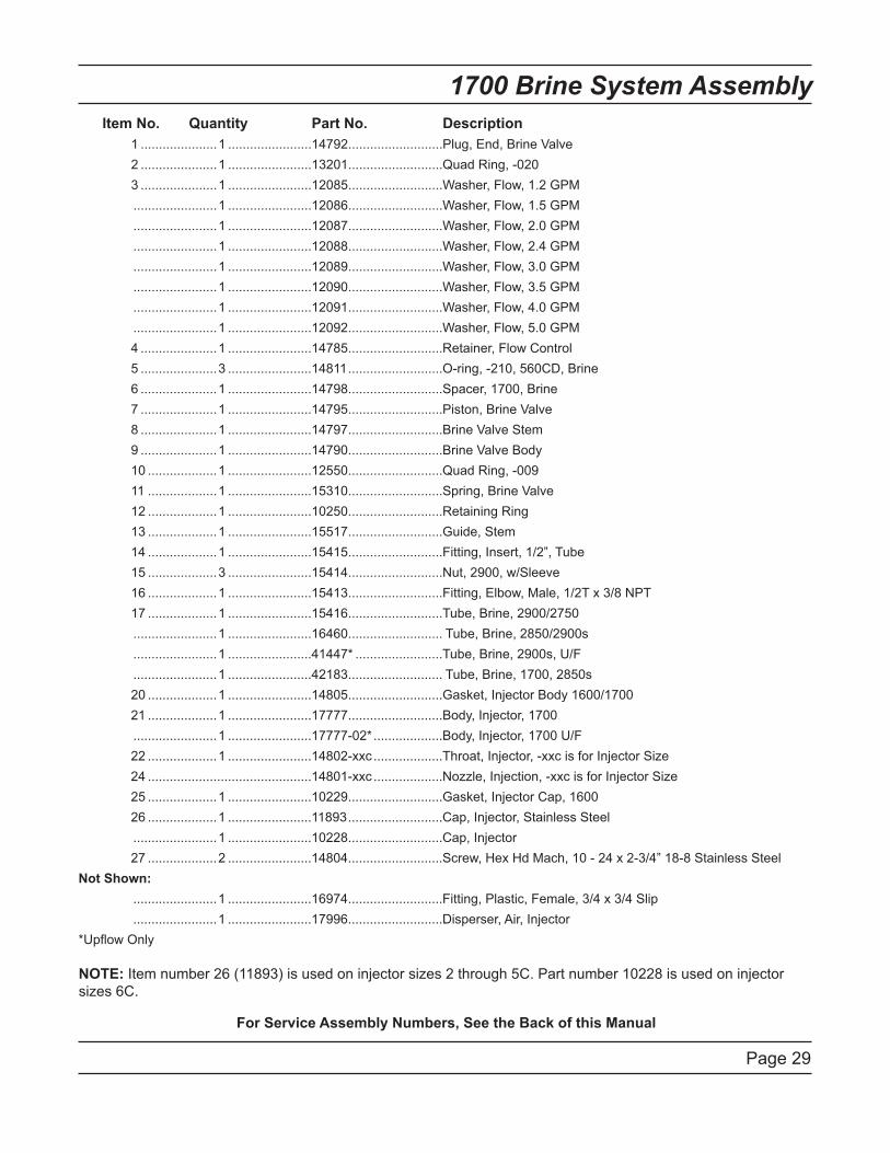
Page 29
1700 Brine System Assembly
Item No. Quantity Part No. Description
1 .....................1 .......................14792 ..........................Plug, End, Brine Valve
2 .....................1 .......................13201 ..........................Quad Ring, -020
3 .....................1 .......................12085 ..........................Washer, Flow, 1.2 GPM
.......................1 .......................12086 ..........................Washer, Flow, 1.5 GPM
.......................1 .......................12087 ..........................Washer, Flow, 2.0 GPM
.......................1 .......................12088 ..........................Washer, Flow, 2.4 GPM
.......................1 .......................12089 ..........................Washer, Flow, 3.0 GPM
.......................1 .......................12090 ..........................Washer, Flow, 3.5 GPM
.......................1 .......................12091 ..........................Washer, Flow, 4.0 GPM
.......................1 .......................12092 ..........................Washer, Flow, 5.0 GPM
4 .....................1 .......................14785 ..........................Retainer, Flow Control
5 .....................3 .......................14811 ..........................O-ring, -210, 560CD, Brine
6 .....................1 .......................14798 ..........................Spacer, 1700, Brine
7 .....................1 .......................14795 ..........................Piston, Brine Valve
8 .....................1 .......................14797 ..........................Brine Valve Stem
9 .....................1 .......................14790 ..........................Brine Valve Body
10 ...................1 .......................12550 ..........................Quad Ring, -009
11 ...................1 .......................15310 ..........................Spring, Brine Valve
12 ...................1 .......................10250 ..........................Retaining Ring
13 ...................1 .......................15517 ..........................Guide, Stem
14 ...................1 .......................15415 ..........................Fitting, Insert, 1/2”, Tube
15 ...................3 .......................15414 ..........................Nut, 2900, w/Sleeve
16 ...................1 .......................15413 ..........................Fitting, Elbow, Male, 1/2T x 3/8 NPT
17 ...................1 .......................15416 ..........................Tube, Brine, 2900/2750
.......................1 .......................16460 .......................... Tube, Brine, 2850/2900s
.......................1 .......................41447* ........................Tube, Brine, 2900s, U/F
.......................1 .......................42183 .......................... Tube, Brine, 1700, 2850s
20 ...................1 .......................14805 ..........................Gasket, Injector Body 1600/1700
21 ...................1 .......................17777 ..........................Body, Injector, 1700
.......................1 .......................17777-02* ...................Body, Injector, 1700 U/F
22 ...................1 .......................14802-xxc ...................Throat, Injector, -xxc is for Injector Size
24 .............................................14801-xxc ...................Nozzle, Injection, -xxc is for Injector Size
25 ...................1 .......................10229 ..........................Gasket, Injector Cap, 1600
26 ...................1 .......................11893 ..........................Cap, Injector, Stainless Steel
.......................1 .......................10228 ..........................Cap, Injector
27 ...................2 .......................14804 ..........................Screw, Hex Hd Mach, 10 - 24 x 2-3/4” 18-8 Stainless Steel
Not Shown:
.......................1 .......................16974 ..........................Fitting, Plastic, Female, 3/4 x 3/4 Slip
.......................1 .......................17996 ..........................Disperser, Air, Injector
*Upflow Only
NOTE: Item number 26 (11893) is used on injector sizes 2 through 5C. Part number 10228 is used on injector
sizes 6C.
For Service Assembly Numbers, See the Back of this Manual
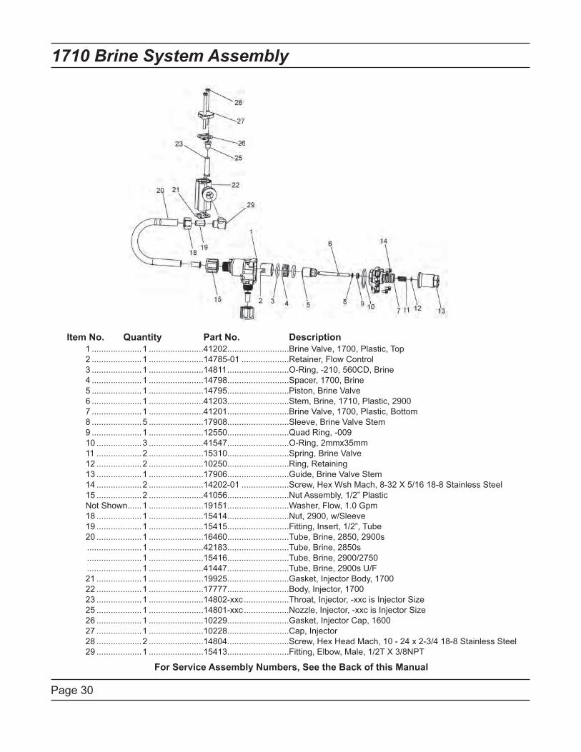
Page 30
Item No. Quantity Part No. Description
1 .....................1 .......................41202 ..........................Brine Valve, 1700, Plastic, Top
2 .....................1 .......................14785-01 ....................Retainer, Flow Control
3 .....................1 .......................14811 ..........................O-Ring, -210, 560CD, Brine
4 .....................1 .......................14798 ..........................Spacer, 1700, Brine
5 .....................1 .......................14795 ..........................Piston, Brine Valve
6 .....................1 .......................41203 ..........................Stem, Brine, 1710, Plastic, 2900
7 .....................1 .......................41201 ..........................Brine Valve, 1700, Plastic, Bottom
8 .....................5 .......................17908 ..........................Sleeve, Brine Valve Stem
9 .....................1 .......................12550 ..........................Quad Ring, -009
10 ...................3 .......................41547 ..........................O-Ring, 2mmx35mm
11 ...................2 .......................15310 ..........................Spring, Brine Valve
12 ...................2 .......................10250 ..........................Ring, Retaining
13 ...................1 .......................17906 ..........................Guide, Brine Valve Stem
14 ...................2 .......................14202-01 ....................Screw, Hex Wsh Mach, 8-32 X 5/16 18-8 Stainless Steel
15 ...................2 .......................41056 ..........................Nut Assembly, 1/2” Plastic
Not Shown......1 .......................19151 ..........................Washer, Flow, 1.0 Gpm
18 ...................1 .......................15414 ..........................Nut, 2900, w/Sleeve
19 ...................1 .......................15415 ..........................Fitting, Insert, 1/2”, Tube
20 ...................1 .......................16460 ..........................Tube, Brine, 2850, 2900s
.......................1 .......................42183 ..........................Tube, Brine, 2850s
.......................1 .......................15416 ..........................Tube, Brine, 2900/2750
.......................1 .......................41447 ..........................Tube, Brine, 2900s U/F
21 ...................1 .......................19925 ..........................Gasket, Injector Body, 1700
22 ...................1 .......................17777 ..........................Body, Injector, 1700
23 ...................1 .......................14802-xxc ...................Throat, Injector, -xxc is Injector Size
25 ...................1 .......................14801-xxc ...................Nozzle, Injector, -xxc is Injector Size
26 ...................1 .......................10229 ..........................Gasket, Injector Cap, 1600
27 ...................1 .......................10228 ..........................Cap, Injector
28 ...................2 .......................14804 ..........................Screw, Hex Head Mach, 10 - 24 x 2-3/4 18-8 Stainless Steel
29 ...................1 .......................15413 ..........................Fitting, Elbow, Male, 1/2T X 3/8NPT
1710 Brine System Assembly
For Service Assembly Numbers, See the Back of this Manual
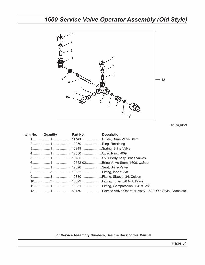
Page 31
1600 Service Valve Operator Assembly (Old Style)
Item No. Quantity Part No. Description
1 ................... 1 .................... 11749 ......................Guide, Brine Valve Stem
2 ................... 1 .................... 10250 ......................Ring, Retaining
3 ................... 1 .................... 10249 ......................Spring, Brine Valve
4 ................... 1 .................... 12550 ......................Quad Ring, -009
5 ................... 1 .................... 10785 ......................SVO Body Assy Brass Valves
6 ................... 1 .................... 12552-02 .................Brine Valve Stem, 1600, w/Seat
7 ................... 1 .................... 12626 ......................Seat, Brine Valve
8 ................... 3 .................... 10332 ......................Fitting, Insert, 3/8
9 ................... 3 .................... 10330 ......................Fitting, Sleeve, 3/8 Celcon
10 ................. 3 .................... 10329 ......................Fitting, Tube, 3/8 Nut, Brass
11 ................. 1 .................... 10331 ......................Fitting, Compression, 1/4” x 3/8”
12 ................. 1 .................... 60150 ......................Service Valve Operator, Assy, 1600, Old Style, Complete
60150_REVA
12
For Service Assembly Numbers, See the Back of this Manual
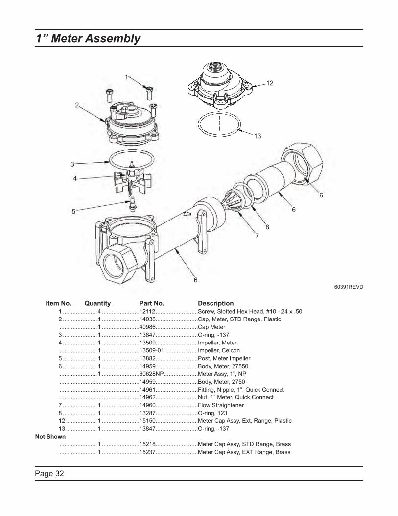
Page 32
1” Meter Assembly
Item No. Quantity Part No. Description
1 .....................4 .......................12112 ..........................Screw, Slotted Hex Head, #10 - 24 x .50
2 .....................1 .......................14038 ..........................Cap, Meter, STD Range, Plastic
.......................1 .......................40986 ..........................Cap Meter
3 .....................1 .......................13847 ..........................O-ring, -137
4 .....................1 .......................13509 ..........................Impeller, Meter
.......................1 .......................13509-01 ....................Impeller, Celcon
5 .....................1 .......................13882 ..........................Post, Meter Impeller
6 .....................1 .......................14959 ..........................Body, Meter, 27550
.......................1 .......................60628NP .....................Meter Assy, 1”, NP
.................................................14959 ..........................Body, Meter, 2750
.................................................14961 ..........................Fitting, Nipple, 1”, Quick Connect
.................................................14962 ..........................Nut, 1” Meter, Quick Connect
7 .....................1 .......................14960 ..........................Flow Straightener
8 .....................1 .......................13287 ..........................O-ring, 123
12 ...................1 .......................15150 ..........................Meter Cap Assy, Ext, Range, Plastic
13 ...................1 .......................13847 ..........................O-ring, -137
Not Shown
.......................1 .......................15218 ..........................Meter Cap Assy, STD Range, Brass
.......................1 .......................15237 ..........................Meter Cap Assy, EXT Range, Brass
1
2
3
4
5
6
7
8
12
13
6
660391REVD
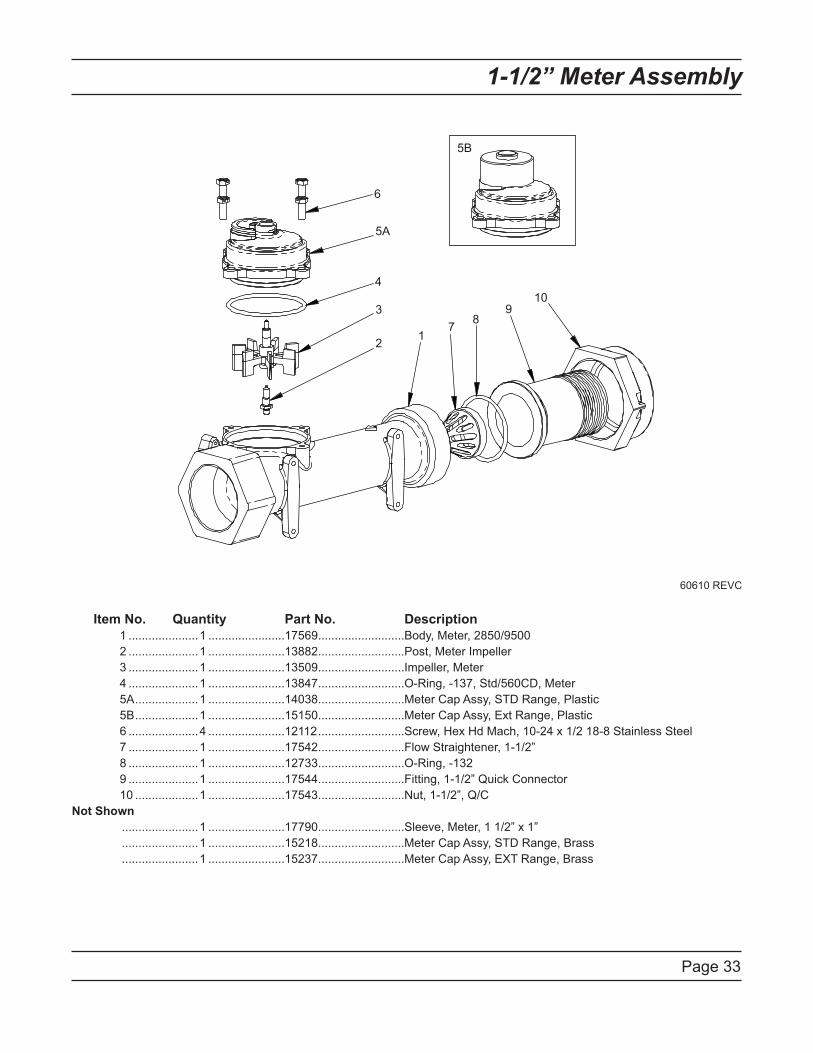
Page 33
1-1/2” Meter Assembly
Item No. Quantity Part No. Description
1 .....................1 .......................17569 ..........................Body, Meter, 2850/9500
2 .....................1 .......................13882 ..........................Post, Meter Impeller
3 .....................1 .......................13509 ..........................Impeller, Meter
4 .....................1 .......................13847 ..........................O-Ring, -137, Std/560CD, Meter
5A ...................1 .......................14038 ..........................Meter Cap Assy, STD Range, Plastic
5B ...................1 .......................15150 ..........................Meter Cap Assy, Ext Range, Plastic
6 .....................4 .......................12112 ..........................Screw, Hex Hd Mach, 10-24 x 1/2 18-8 Stainless Steel
7 .....................1 .......................17542 ..........................Flow Straightener, 1-1/2”
8 .....................1 .......................12733 ..........................O-Ring, -132
9 .....................1 .......................17544 ..........................Fitting, 1-1/2” Quick Connector
10 ...................1 .......................17543 ..........................Nut, 1-1/2”, Q/C
Not Shown
.......................1 .......................17790 ..........................Sleeve, Meter, 1 1/2” x 1”
.......................1 .......................15218 ..........................Meter Cap Assy, STD Range, Brass
.......................1 .......................15237 ..........................Meter Cap Assy, EXT Range, Brass
12
3
4
6
78
910
5A
5B
60610 REVC
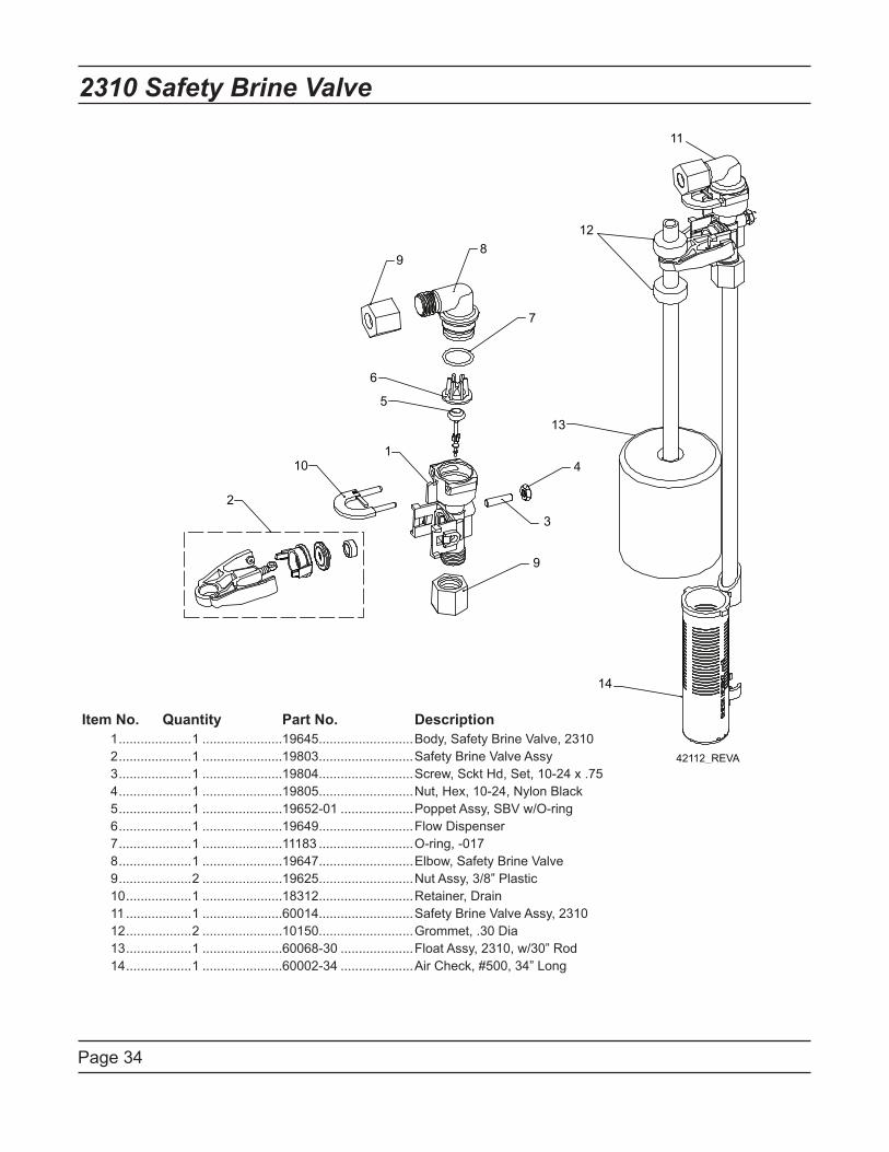
Page 34
2310 Safety Brine Valve
Item No. Quantity Part No. Description
1 ....................1 ......................19645 ..........................Body, Safety Brine Valve, 2310
2 ....................1 ......................19803 ..........................Safety Brine Valve Assy
3 ....................1 ......................19804 ..........................Screw, Sckt Hd, Set, 10-24 x .75
4 ....................1 ......................19805 ..........................Nut, Hex, 10-24, Nylon Black
5 ....................1 ......................19652-01 ....................Poppet Assy, SBV w/O-ring
6 ....................1 ......................19649 ..........................Flow Dispenser
7 ....................1 ......................11183 ..........................O-ring, -017
8 ....................1 ......................19647 ..........................Elbow, Safety Brine Valve
9 ....................2 ......................19625 ..........................Nut Assy, 3/8” Plastic
10 ..................1 ......................18312 ..........................Retainer, Drain
11 ..................1 ......................60014 ..........................Safety Brine Valve Assy, 2310
12 ..................2 ......................10150 ..........................Grommet, .30 Dia
13 ..................1 ......................60068-30 ....................Float Assy, 2310, w/30” Rod
14 ..................1 ......................60002-34 ....................Air Check, #500, 34” Long
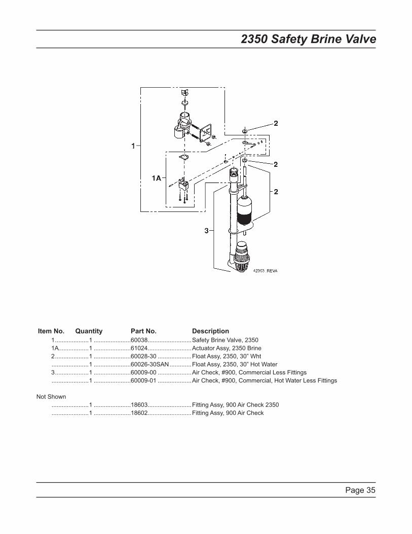
Page 35
2350 Safety Brine Valve
Item No. Quantity Part No. Description
1 ....................1 ......................60038 ..........................Safety Brine Valve, 2350
1A..................1 ......................61024 ..........................Actuator Assy, 2350 Brine
2 ....................1 ......................60028-30 ....................Float Assy, 2350, 30” Wht
......................1 ......................60026-30SAN .............Float Assy, 2350, 30” Hot Water
3 ....................1 ......................60009-00 ....................Air Check, #900, Commercial Less Fittings
......................1 ......................60009-01 ....................Air Check, #900, Commercial, Hot Water Less Fittings
Not Shown
......................1 ......................18603 ..........................Fitting Assy, 900 Air Check 2350
......................1 ......................18602 ..........................Fitting Assy, 900 Air Check
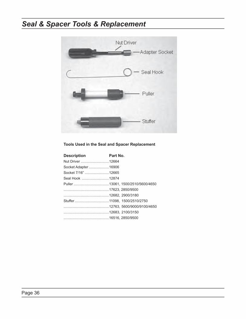
Page 36
Seal & Spacer Tools & Replacement
Tools Used in the Seal and Spacer Replacement
Description Part No.
Nut Driver ............................12664
Socket Adapter ....................16906
Socket 7/16” ........................12665
Seal Hook ...........................12874
Puller ...................................13061, 1500/2510/5600/4650
.............................................17623, 2850/9500
.............................................12682, 2900/3180
Stuffer ..................................11098, 1500/2510/2750
.............................................12763, 5600/9000/9100/4650
.............................................12683, 2100/3150
.............................................16516, 2850/9500
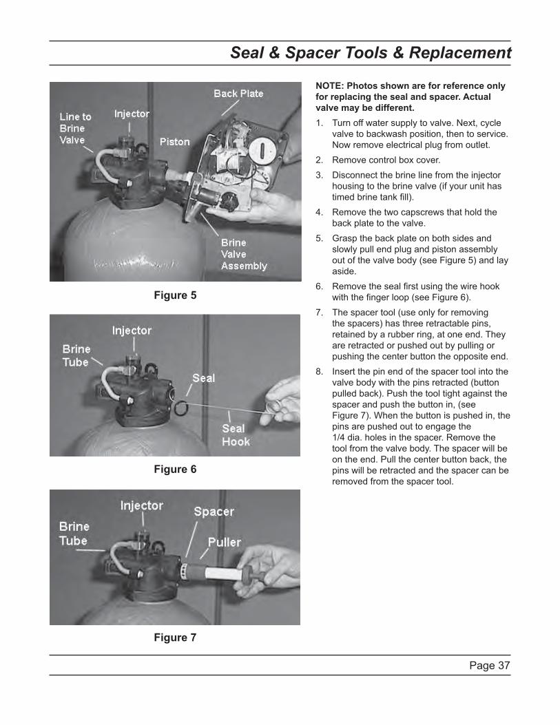
Page 37
Seal & Spacer Tools & Replacement
NOTE: Photos shown are for reference only
for replacing the seal and spacer. Actual
valve may be different.
Turn off water supply to valve. Next, cycle 1.
valve to backwash position, then to service.
Now remove electrical plug from outlet.
Remove control box cover.2.
Disconnect the brine line from the injector 3.
housing to the brine valve (if your unit has
timed brine tank fill).
Remove the two capscrews that hold the 4.
back plate to the valve.
Grasp the back plate on both sides and 5.
slowly pull end plug and piston assembly
out of the valve body (see Figure 5) and lay
aside.
Remove the seal first using the wire hook 6.
with the finger loop (see Figure 6).
The spacer tool (use only for removing 7.
the spacers) has three retractable pins,
retained by a rubber ring, at one end. They
are retracted or pushed out by pulling or
pushing the center button the opposite end.
Insert the pin end of the spacer tool into the 8.
valve body with the pins retracted (button
pulled back). Push the tool tight against the
spacer and push the button in, (see
Figure 7). When the button is pushed in, the
pins are pushed out to engage the
1/4 dia. holes in the spacer. Remove the
tool from the valve body. The spacer will be
on the end. Pull the center button back, the
pins will be retracted and the spacer can be
removed from the spacer tool.
Figure 5
Figure 6
Figure 7
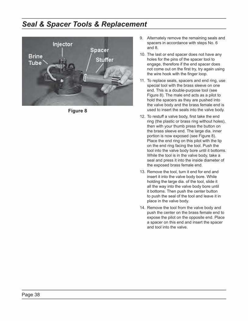
Page 38
Seal & Spacer Tools & Replacement
Figure 8
Alternately remove the remaining seals and 9.
spacers in accordance with steps No. 6
and 8.
The last or end spacer does not have any 10.
holes for the pins of the spacer tool to
engage, therefore if the end spacer does
not come out on the first try, try again using
the wire hook with the finger loop.
To replace seals, spacers and end ring, use 11.
special tool with the brass sleeve on one
end. This is a double-purpose tool (see
Figure 8). The male end acts as a pilot to
hold the spacers as they are pushed into
the valve body and the brass female end is
used to insert the seals into the valve body.
To restuff a valve body, first take the end 12.
ring (the plastic or brass ring without holes),
then with your thumb press the button on
the brass sleeve end. The large dia. inner
portion is now exposed (see Figure 8).
Place the end ring on this pilot with the lip
on the end ring facing the tool. Push the
tool into the valve body bore until it bottoms.
While the tool is in the valve body, take a
seal and press it into the inside diameter of
the exposed brass female end.
Remove the tool, turn it end for end and 13.
insert it into the valve body bore. While
holding the large dia. of the tool, slide it
all the way into the valve body bore until
it bottoms. Then push the center button
to push the seal of the tool and leave it in
place in the valve body.
Remove the tool from the valve body and 14.
push the center on the brass female end to
expose the pilot on the opposite end. Place
a spacer on this end and insert the spacer
and tool into the valve.
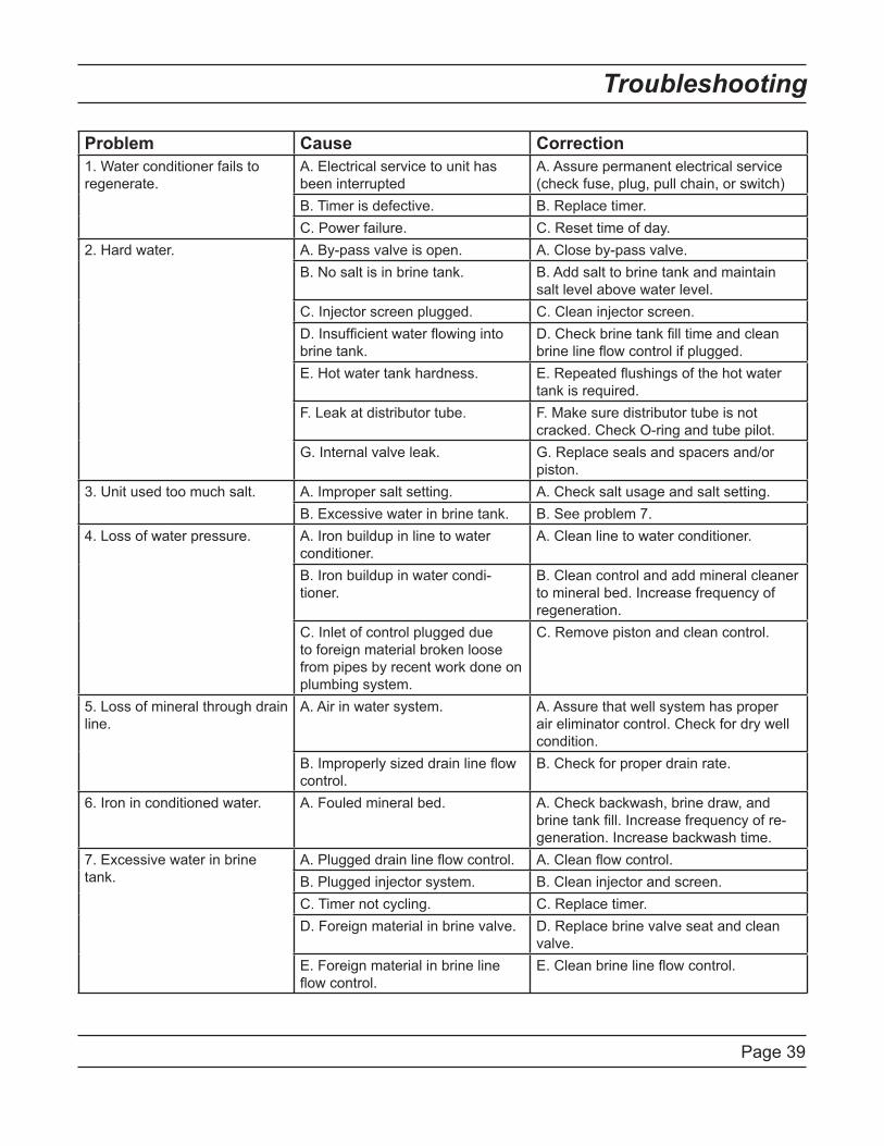
Page 39
Problem Cause Correction
1. Water conditioner fails to
regenerate.
A. Electrical service to unit has
been interrupted
A. Assure permanent electrical service
(check fuse, plug, pull chain, or switch)
B. Timer is defective. B. Replace timer.
C. Power failure. C. Reset time of day.
2. Hard water. A. By-pass valve is open. A. Close by-pass valve.
B. No salt is in brine tank. B. Add salt to brine tank and maintain
salt level above water level.
C. Injector screen plugged. C. Clean injector screen.
D. Insufficient water flowing into
brine tank.
D. Check brine tank fill time and clean
brine line flow control if plugged.
E. Hot water tank hardness. E. Repeated flushings of the hot water
tank is required.
F. Leak at distributor tube. F. Make sure distributor tube is not
cracked. Check O-ring and tube pilot.
G. Internal valve leak. G. Replace seals and spacers and/or
piston.
3. Unit used too much salt. A. Improper salt setting. A. Check salt usage and salt setting.
B. Excessive water in brine tank. B. See problem 7.
4. Loss of water pressure. A. Iron buildup in line to water
conditioner.
A. Clean line to water conditioner.
B. Iron buildup in water condi-
tioner.
B. Clean control and add mineral cleaner
to mineral bed. Increase frequency of
regeneration.
C. Inlet of control plugged due
to foreign material broken loose
from pipes by recent work done on
plumbing system.
C. Remove piston and clean control.
5. Loss of mineral through drain
line.
A. Air in water system. A. Assure that well system has proper
air eliminator control. Check for dry well
condition.
B. Improperly sized drain line flow
control.
B. Check for proper drain rate.
6. Iron in conditioned water. A. Fouled mineral bed. A. Check backwash, brine draw, and
brine tank fill. Increase frequency of re-
generation. Increase backwash time.
7. Excessive water in brine
tank.
A. Plugged drain line flow control. A. Clean flow control.
B. Plugged injector system. B. Clean injector and screen.
C. Timer not cycling. C. Replace timer.
D. Foreign material in brine valve. D. Replace brine valve seat and clean
valve.
E. Foreign material in brine line
flow control.
E. Clean brine line flow control.
Troubleshooting
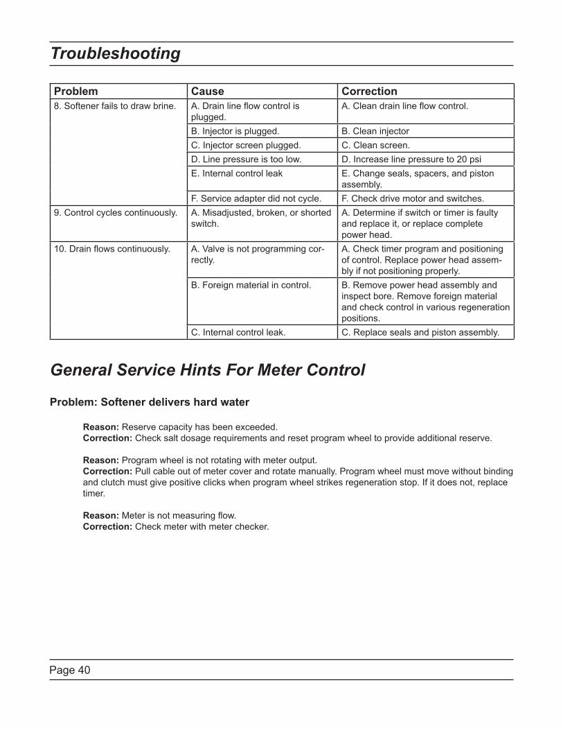
Page 40
Problem Cause Correction
8. Softener fails to draw brine. A. Drain line flow control is
plugged.
A. Clean drain line flow control.
B. Injector is plugged. B. Clean injector
C. Injector screen plugged. C. Clean screen.
D. Line pressure is too low. D. Increase line pressure to 20 psi
E. Internal control leak E. Change seals, spacers, and piston
assembly.
F. Service adapter did not cycle. F. Check drive motor and switches.
9. Control cycles continuously. A. Misadjusted, broken, or shorted
switch.
A. Determine if switch or timer is faulty
and replace it, or replace complete
power head.
10. Drain flows continuously. A. Valve is not programming cor-
rectly.
A. Check timer program and positioning
of control. Replace power head assem-
bly if not positioning properly.
B. Foreign material in control. B. Remove power head assembly and
inspect bore. Remove foreign material
and check control in various regeneration
positions.
C. Internal control leak. C. Replace seals and piston assembly.
General Service Hints For Meter Control
Problem: Softener delivers hard water
Reason: Reserve capacity has been exceeded.
Correction: Check salt dosage requirements and reset program wheel to provide additional reserve.
Reason: Program wheel is not rotating with meter output.
Correction: Pull cable out of meter cover and rotate manually. Program wheel must move without binding
and clutch must give positive clicks when program wheel strikes regeneration stop. If it does not, replace
timer.
Reason: Meter is not measuring flow.
Correction: Check meter with meter checker.
Troubleshooting
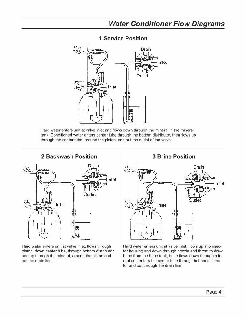
Page 41
Water Conditioner Flow Diagrams
1 Service Position
Hard water enters unit at valve inlet and flows down through the mineral in the mineral
tank. Conditioned water enters center tube through the bottom distributor, then flows up
through the center tube, around the piston, and out the outlet of the valve.
2 Backwash Position 3 Brine Position
Hard water enters unit at valve inlet, flows through
piston, down center tube, through bottom distributor,
and up through the mineral, around the piston and
out the drain line.
Hard water enters unit at valve inlet, flows up into injec-
tor housing and down through nozzle and throat to draw
brine from the brine tank, brine flows down through min-
eral and enters the center tube through bottom distribu-
tor and out through the drain line.
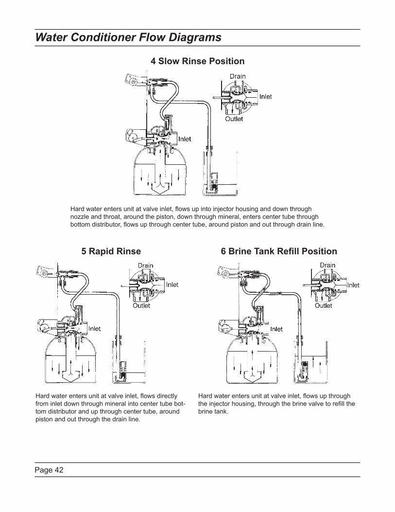
Page 42
Water Conditioner Flow Diagrams
4 Slow Rinse Position
5 Rapid Rinse 6 Brine Tank Refill Position
Hard water enters unit at valve inlet, flows up into injector housing and down through
nozzle and throat, around the piston, down through mineral, enters center tube through
bottom distributor, flows up through center tube, around piston and out through drain line.
Hard water enters unit at valve inlet, flows directly
from inlet down through mineral into center tube bot-
tom distributor and up through center tube, around
piston and out through the drain line.
Hard water enters unit at valve inlet, flows up through
the injector housing, through the brine valve to refill the
brine tank.
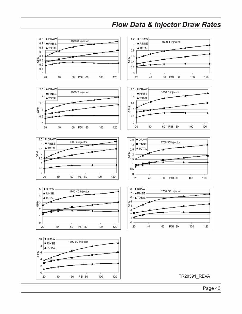
Page 43
Flow Data & Injector Draw Rates
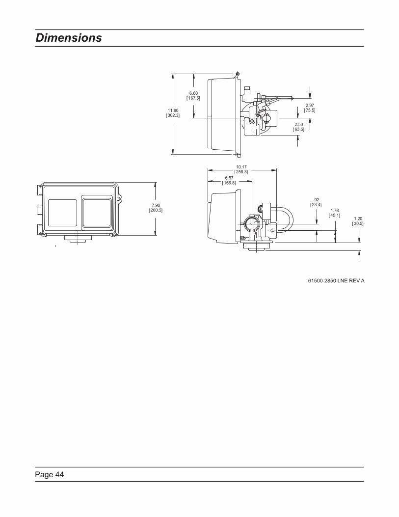
Page 44
Dimensions
2.97[75.5]
2.50[63.5]
6.60[167.5]
11.90[302.3]
7.90[200.5]
10.17[258.3]
6.57[166.8]
1.20[30.5]
1.78[45.1]
.92[ 23.4]
61500-2850 LNE REV A

Page 45
Notes
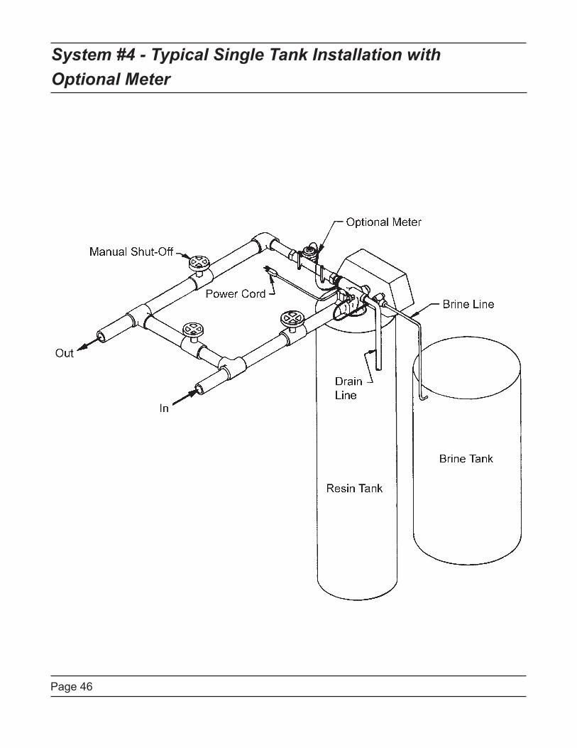
Page 46
System #4 - Typical Single Tank Installation with
Optional Meter
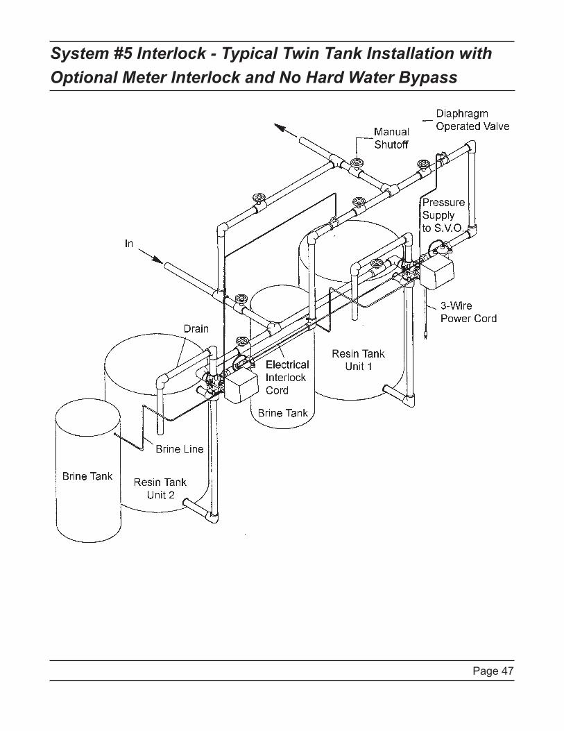
Page 47
System #5 Interlock - Typical Twin Tank Installation with
Optional Meter Interlock and No Hard Water Bypass
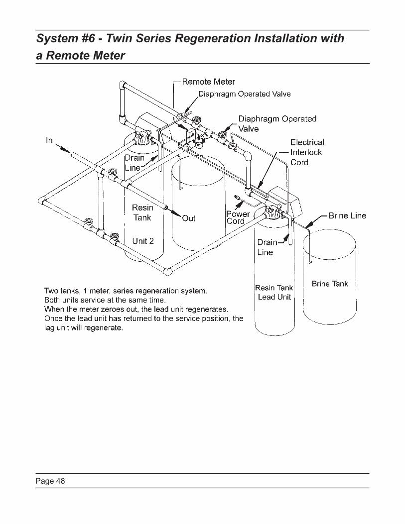
Page 48
System #6 - Twin Series Regeneration Installation with
a Remote Meter
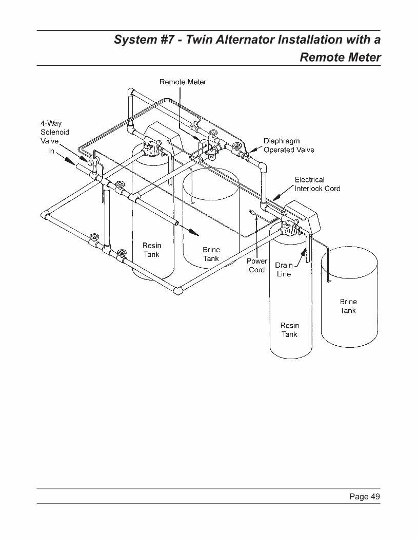
Page 49
System #7 - Twin Alternator Installation with a
Remote Meter
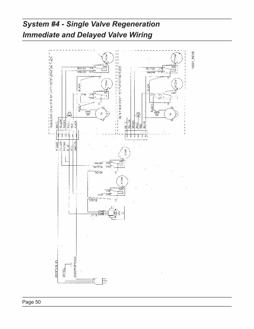
Page 50
System #4 - Single Valve Regeneration
Immediate and Delayed Valve Wiring
19
20
1_
RE
VB
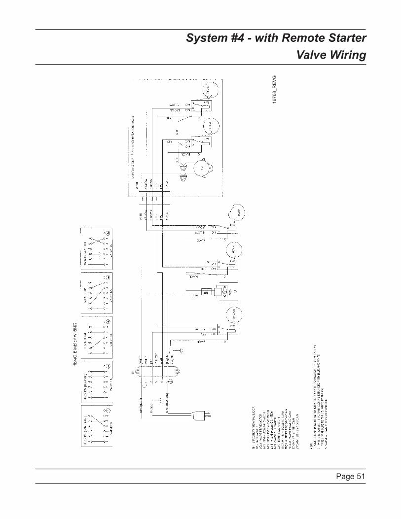
Page 51
System #4 - with Remote Starter
Valve Wiring
16
76
8_
RE
VG
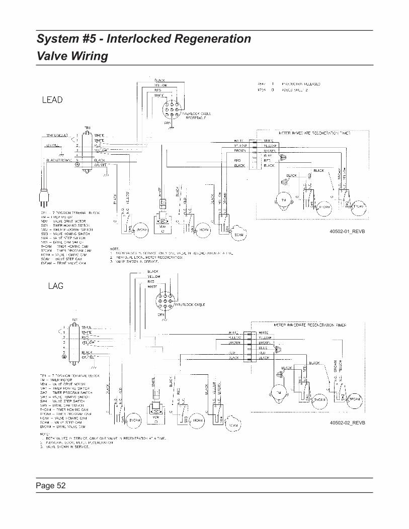
Page 52
System #5 - Interlocked Regeneration
Valve Wiring
40502-01_REVB
40502-02_REVB
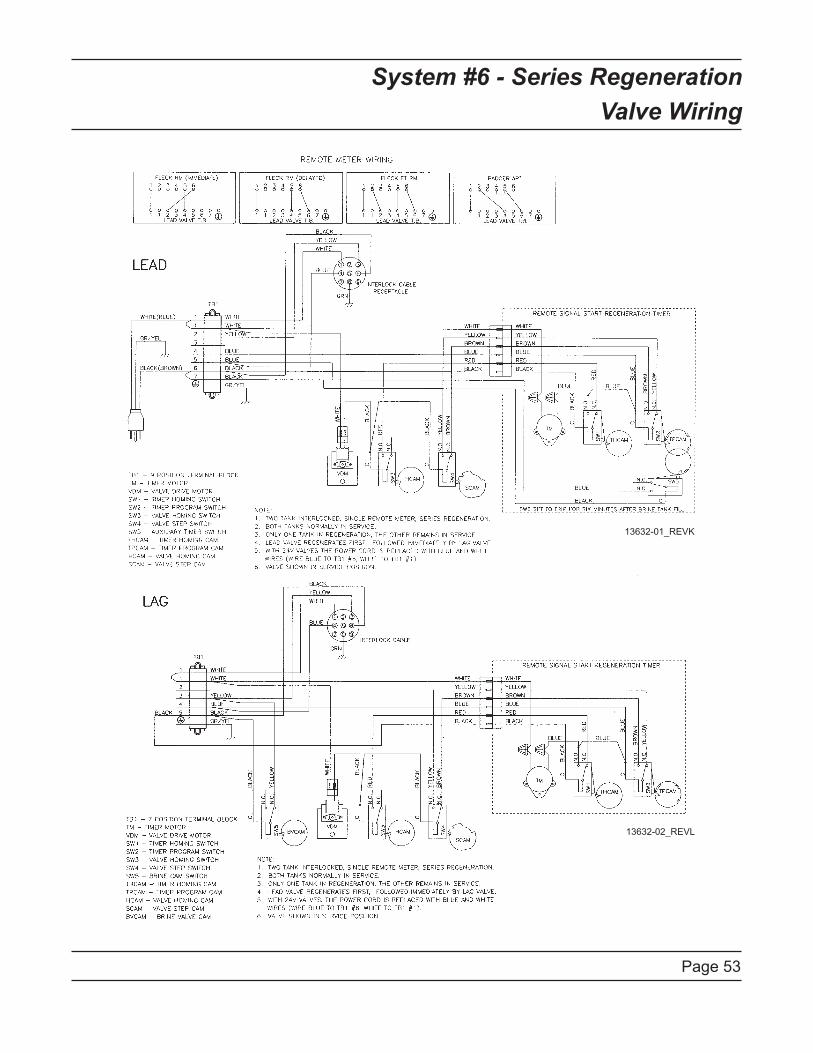
Page 53
System #6 - Series Regeneration
Valve Wiring
13632-01_REVK
13632-02_REVL
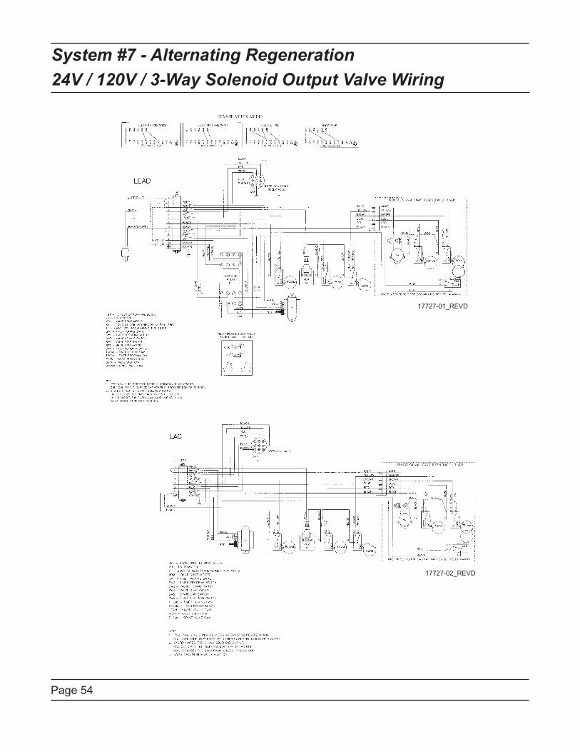
Page 54
System #7 - Alternating Regeneration
24V / 120V / 3-Way Solenoid Output Valve Wiring
17727-01_REVD
17727-02_REVD
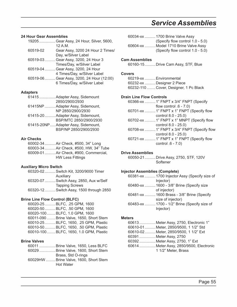
Page 55
Service Assemblies
24 Hour Gear Assemblies
19205 ...............Gear Assy, 24 Hour, Silver, 5600,
12 A.M.
60519-02 Gear Assy, 3200 24 Hour 2 Times/
Day, w/Silver Label
60519-03 ..........Gear Assy, 3200, 24 Hour 3
Times/Day, w/Silver Label
60519-04 ..........Gear Assy, 3200, 24 Hour
4 Times/Day, w/Silver Label
60519-06 ..........Gear Assy, 3200, 24 Hour (12:00)
6 Times/Day, w/Silver Label
Adapters
61415 ...............Adapter Assy, Sidemount
2850/2900/2930
61415NP ..........Adapter Assy, Sidemount,
NP 2850/2900/2930
61415-20 ..........Adapter Assy, Sidemount,
BSP/MTC 2850/2900/2930
61415-20NP .....Adapter Assy, Sidemount,
BSP/NP 2850/2900/2930
Air Checks
60002-34 ..........Air Check, #500, 34” Long
60003-34 ..........Air Check, #500, HW, 34” Tube
60009-01 ..........Air Check, #900, Commercial,
HW Less Fittings
Auxiliary Micro Switch
60320-02 ..........Switch Kit, 3200/9000 Timer
Auxiliary
60320-07 ..........Switch Assy, 2850, Aux w/Self
Tapping Screws
60320-12 ..........Switch Assy, 1500 through 2850
Brine Line Flow Control (BLFC)
60020-25 ..........BLFC, .25 GPM, 1600
60020-50 ..........BLFC, .50 GPM, 1600
60020-100 ........BLFC, 1.0 GPM, 1600
60011-090 ........Brine Valve, 1650, Short Stem
60010-25 ..........BLFC, 1650, .25 GPM, Plastic
60010-50 ..........BLFC, 1650, .50 GPM, Plastic
60010-100 ........BLFC, 1650, 1.0 GPM, Plastic
Brine Valves
60011 ...............Brine Valve, 1650, Less BLFC
60029 ...............Brine Valve, 1600, Short Stem
Brass, Std O-rings
60029HW .........Brine Valve, 1600, Short Stem
Hot Water
60034-xx ..........1700 Brine Valve Assy
(Specify flow control 1.0 - 5.0)
60604-xx ..........Model 1710 Brine Valve Assy
(Specify flow control 1.0 - 5.0)
Cam Assemblies
60160-15 ..........Drive Cam Assy, STF, Blue
Covers
60219-xx ..........Environmental
60232-xx ..........Designer 2 Piece
60232-110 ........Cover, Designer, 1 Pc Black
Drain Line Flow Controls
60366-xx ..........1” FNPT x 3/4” FNPT (Specify
flow control .6 - 7.0)
60701-xx ..........1” FNPT x 1” FNPT (Specify flow
control 8.0 - 25.0)
60702-xx ..........1” FNPT x 1” MNPT (Specify flow
control 8.0 - 25.0)
60708-xx ..........1” FNPT x 3/4” FNPT (Specify flow
control 8.0 - 25.0)
60721-xx ..........1” FNPT x 1” FNPT (Specify flow
control .6 - 7.0)
Drive Assemblies
60050-21 ..........Drive Assy, 2750, STF, 120V
Softener
Injector Assemblies (Complete)
60381-xx ..........1700 Injector Assy (Specify size of
Injector)
60480-xx ..........1600 - 3/8” Brine (Specify size
of injector)
60481-xx ..........1600 Brass - 3/8” Brine (Specify
size of injector)
60483-xx ..........1700 - 1/2” Brine (Specify size of
Injector)
Meters
60613 ...............Meter Assy, 2750, Electronic 1”
60610-01 ..........Meter, 2850/9500, 1 1/2” Std
60610-02 ..........Meter, 2850/9500, 1 1/2” Ext
60391 ...............Meter Assy, 2750
60392 ...............Meter Assy, 2750, 1” Ext
60614 ...............Meter Assy, 2850/9500, Electronic
1 1/2” Meter, Brass
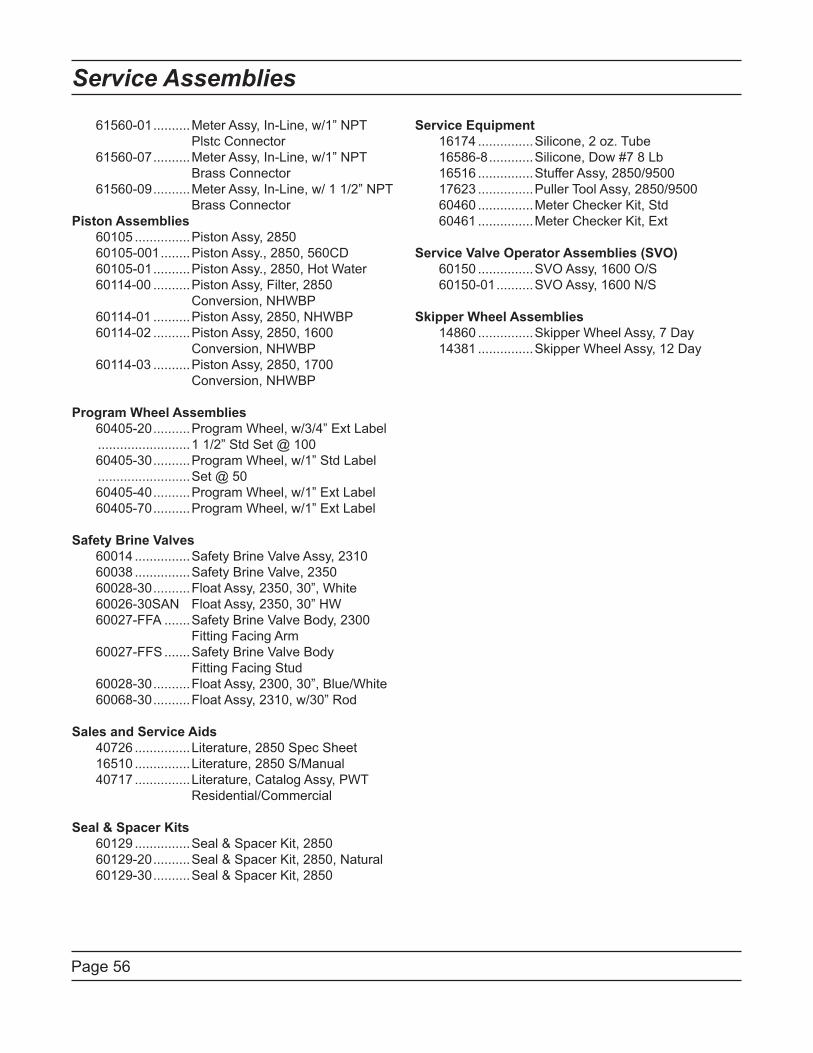
Page 56
Service Assemblies
61560-01 ..........Meter Assy, In-Line, w/1” NPT
Plstc Connector
61560-07 ..........Meter Assy, In-Line, w/1” NPT
Brass Connector
61560-09 ..........Meter Assy, In-Line, w/ 1 1/2” NPT
Brass Connector
Piston Assemblies
60105 ...............Piston Assy, 2850
60105-001 ........Piston Assy., 2850, 560CD
60105-01 ..........Piston Assy., 2850, Hot Water
60114-00 ..........Piston Assy, Filter, 2850
Conversion, NHWBP
60114-01 ..........Piston Assy, 2850, NHWBP
60114-02 ..........Piston Assy, 2850, 1600
Conversion, NHWBP
60114-03 ..........Piston Assy, 2850, 1700
Conversion, NHWBP
Program Wheel Assemblies
60405-20 ..........Program Wheel, w/3/4” Ext Label
.........................1 1/2” Std Set @ 100
60405-30 ..........Program Wheel, w/1” Std Label
.........................Set @ 50
60405-40 ..........Program Wheel, w/1” Ext Label
60405-70 ..........Program Wheel, w/1” Ext Label
Safety Brine Valves
60014 ...............Safety Brine Valve Assy, 2310
60038 ...............Safety Brine Valve, 2350
60028-30 ..........Float Assy, 2350, 30”, White
60026-30SAN Float Assy, 2350, 30” HW
60027-FFA .......Safety Brine Valve Body, 2300
Fitting Facing Arm
60027-FFS .......Safety Brine Valve Body
Fitting Facing Stud
60028-30 ..........Float Assy, 2300, 30”, Blue/White
60068-30 ..........Float Assy, 2310, w/30” Rod
Sales and Service Aids
40726 ...............Literature, 2850 Spec Sheet
16510 ...............Literature, 2850 S/Manual
40717 ...............Literature, Catalog Assy, PWT
Residential/Commercial
Seal & Spacer Kits
60129 ...............Seal & Spacer Kit, 2850
60129-20 ..........Seal & Spacer Kit, 2850, Natural
60129-30 ..........Seal & Spacer Kit, 2850
Service Equipment
16174 ...............Silicone, 2 oz. Tube
16586-8 ............Silicone, Dow #7 8 Lb
16516 ...............Stuffer Assy, 2850/9500
17623 ...............Puller Tool Assy, 2850/9500
60460 ...............Meter Checker Kit, Std
60461 ...............Meter Checker Kit, Ext
Service Valve Operator Assemblies (SVO)
60150 ...............SVO Assy, 1600 O/S
60150-01 ..........SVO Assy, 1600 N/S
Skipper Wheel Assemblies
14860 ...............Skipper Wheel Assy, 7 Day
14381 ...............Skipper Wheel Assy, 12 Day

Page 57

Page 58

Page 59

P/N 16510 Rev. G 10-13-08