Embed Size (px)
Citation preview

OWNERS MANUAL
VEGA 30 SERIES
WILLARD BOAT WORKS, INC.VEGA DIVISIONCOSTA MESA, CALIFORNIA
VEGA 30 OWNER'S MANUAL
WELCOME We welcome you to the growing group of discerning yachtsmen who own and cruise in their Vega 30 Trawlers. Willard Boat Works takes great pride in their tradition of quality products. We have sought to anticipate your needs and desires with respect to safety, convenience, styling, and engineering. We hope you enjoy your new Vega 30 and wish you many hours of pleasant and carefree cruising.
WARRANTIESThe warranties covering this vessel are included with this manual. Please read them carefully. They state in precise terms everything that is covered by these warranties.
IDENTIFICATIONThe official Hull Identification Number, for title and registration purposes, is molded into the hull at the stern just below shear line and slightly to starboard of center. It consists of twelve characters and appears on all hulls manufactured after October 31, 1972, as prescribed by the United States Coast Guard.
HOW TO USE YOUR VEGA 30 OWNER'S MANUALFor ease of reference, the manual has been sectionalized togroup related information together in a quick-to-locate form.You'll find the answers to the most commonly asked questionsabout your Vega 30 in the "Question and Answer" section.
April 25, 1974

TABLE OF CONTENTS
Vega 30 Series
OWNER'S MANUAL
QUESTIONS AND ANSWERS ABOUT YOUR VEGA 30..................1
SECTION A - PROPULSION SYSTEM.............................6
SECTION B - CONTROL SYSTEMS..............................10
SECTION C - ELECTRICAL SYSTEM............................11
SECTION D - FRESHWATER SYSTEM...........................13
SECTION E – GALLEY EQUIPMENT.............................15
SECTION F - SANITATION SYSTEM - VESSEL WASTES............16
SECTION G - BILGE SYSTEM.................................16
SECTION H - TOTAL CARE INFORMATION.......................17
SECTION I - SUGGESTED ONBOARD SPARE PARTS................20
QUESTIONS AND ANSWERS ABOUT YOUR VEGA 30
About Daily OperationQ. Are there any "break-in" precautions for ray boat?
A. The initial break-in period of the engine is 25 to 50 operating hours. During this period the engine should not be run at over 85% of full load and speed.
Q. What grade of diesel fuel should I use?
A. No. 2 Diesel — or "amber colored" fuel should be used.
Q. What is my fuel tank capacity? How can I tell how much fuel I have?
A. Approximately 1OO gallons — 50 gallons in each of two tanks. Provisions are made for checking fuel tanks by dip stick, however, best bet is to keep an Engine Log and at average consumption rate of approximately 1 gallon per hour keep a "running balance" of fuel on hand.
Q. What is engine oil capacity?
A. Oil system of the Perkins 4-107 will initially take six quarts of SAE 30. One quart less is required on oil changes (refer to maintenance schedule) as a quart will remain in the lines at all times and not return to the sump.
Q. What is my fresh water capacity?
A. Approximately 100 gallons — 50 gallons in each of two polyethylene tanks. Voyager has one 100 gallon tank.
Q. When should I check the battery fluid level?
A. About once a month and more frequently during hot weather or continuous running. Fluid level should be at the ring at the bottom of the filler well.
VEGA 30 SERIES - 1 - April 25, 1974

Q. What about engine cooling water?
A. The Perkins 4-107 cooling system incorporates a heat exchanger with cooling water in a closed circuit using fresh water as the cooling medium. Water level in the header tank should be kept topped off to a level approximately one inch below the pressure cap sealing flange. A rust inhibitor additive (such as Mac's 13) is recommended.
About Instruments and ControlsQ. How should I set switches on electrical panel?
A. The following procedure is recommended:
1. With master switch in "OFF" position, check each battery's condition. If voltage range is between 12 and 15 (green band) the battery is well charged.
2. Select the strongest battery for engine starting, turn master switch to that battery, then start your engine. It will require about 15 to 30 minutes engine running time to bring starting battery back up to full charge. Remember alternator charges only to selected battery.
3. If both batteries indicate low charge, turn master switch to "BOTH" position for engine starting.
4. Circuit switches on panels are easily identified for selection as required.
NOTE: Please refer to Electrical Systems in this Manual for detailed description of operation.
Q. How does the battery charger operate?
A. Operates on 110V shore power and should be switched off at panel before starting engine. Please refer to Technical Information Bulletin, which is included in Owner's folio for more detailed information.
Q. What does the Bartell milliampmeter tell me?
A. This is part of the corrosion protection system:
VEGA 30 SERIES - 2 - April 25, 1974

please refer to Bartell Corporation literature included in Owner's folio for complete description of how it functions.
Q. How do I start and stop the engine?
A. Before starting the engine, you should observe the following: Be sure that fuel tank contains sufficient fuel. Open engine heat exchanger raw-water through-hull valve, check coolant level in header tank, check engine and gear box lubricating oil level, turn on battery selector switch and Ignition switch on panel.
Starting the Engine: Place gearbox control in neutral gear. Place engine speed control in advanced speed position (¼ to ½ throttle). Turn key switch clockwise and, after momentarily hearing alarm horn to check its operation, hold down alarm squelch button until oil pressure comes up after engine starts, As soon as engine starts, release the key switch and reduce speed control to idle.
To Stop the Engine: Depress "STOP" button on instrument panel. This activates a solenoid which cuts off the fuel at the fuel injection pump. When the engine ceases to rotate, release stop button and turn key switch to "OFF" position. The alarm squelch button can also be used during the stop procedure until key switch is turned off.
NOTE: In the event the solenoid fails to function properly, fuel can be cut off manually by pulling up on wire cable found on port side of engine between engine block and exhaust manifold. This cable runs from solenoid to cut-off valve at fuel injection pump.
When engine is running, check the following:
1. That oil pressure is registered on gauge.
2. That charging rate is indicated on ammeter.
3. That heat exchange water is discharging overboard.
a. By-pass through hull on port side.
b. Excess by-pass water coming out exhaust aft to cool exhaust line.
VEGA 30 SERIES - 3 - April 25, 1974

Q. What does the engine alarm warning horn tell me?
A. That either oil pressure is too low or water temperature is too high. Shut down engine and find out why. A faulty sender could be responsible for sounding the alarm. Refer to Perkin's Engine Manual "Trouble Shooting".
About the InteriorQ. What should I do about through-hull valves?
A. If your boat is going to be left unattended for a period of time, it is good practice to close all through-hull valves. It is also good practice to always check through-hull valves to assure they are open before start-up. Periodically opening and closing valves assures operability.
Q. How often should I check propeller shaft stuffing box?
A. It is prudent to check during a period of continuous running to determine if it is too hot or too wet. Check frequently during break-in period.
Q. How do I operate the hot and cold pressure water system?
A. Detailed description of the system will be found under Contents, however, with the system filled, which should be done when commissioned, the pressure system operates when the water pressure switch is turned on. Hot water system is operated when engine is running or when on shore power through accessory control panel water heater switch.
Q. How do I operate the galley stove?
A. Refer to Galley Equipment Section of this manual, also Operating and Maintenance Instructions which are included in Owner's folio.
About the ExteriorQ. Is there anything special I should know about care
VEGA 30 SERIES - 4 - April 25, 1974
and maintenance of fiberglass?
A. Yes. Although fiberglass is known as comparatively "maintenance free" material, there are certain things you should know and do to insure good appearance and long life. This subject is covered in the Contents of this Manual under Total Care Information.
About Boat Operation and ManeuveringQ. What should I know about handling characteristics that are peculiar to the Vega 30?
A. 1. The Vega 30 has a left hand turning propeller, therefore, in reverse gear propeller rotation is right hand causing the vessel to back slightly to starboard. With a little practice this can be helpful when docking.
2. Running forward the Vega 30 has very "tight turning" ability due to the large rudder and propeller wash blasting directly against it. For a single screw vessel it is exceptionally maneuverable.
3. Stopping: The Vega 30 is a heavy displacement hull and underway carries a lot of momentum, which determines the length of time required to bring it to rest. In an emergency it can be stopped quite suddenly by reversing the propeller thrust, but for normal handling, it is best to allow time to slow down. Being a full displacement hull with skeg keel and large rudder, it maintains steerage way at very low speed.
VEGA 30 SERIES - 5 - April 25, 1974
SECTION A - PROPULSION SYSTEM
Section A-1: Engine & TransmissionThe Perkins 4-107 diesel engine is a four-cylinder, four-cycle engine, is fresh water cooled, and has a 12-volt 45 amp/alternator. Note that the 4-107 is INDIRECT injection.
The basic engine is manufactured in England and assembled in the United States, using accessories and parts manufactured here, so no special or metric tools are required to service these engines. The assembled engines are distributed throughout the United States by Perkins Engines, Inc. Please note that the manufacturer of Perkins Diesel Engines requires that each new engine installation be checked out in the water at the time of delivery to a customer by one of their local field service engineers in order for their WARRANTY TO BE VALID. A Marine Customer Delivery Report will be executed at this time and a copy will be mailed to you by your nearest Perkins representative, who must also be contacted for all warranty service. Since these are high speed diesels, they must use #2 or amber-colored fuel.
The oil system of the 4-107 will initially take six quarts of SAE 30. This original oil should be replaced after 25 to 50 operating hours with five quarts of SAE 30. One quart less is required on oil changes, which should take place every 150 running hours, as a quart will remain in the lines at all times and not return to the sump.
The disposable paper fuel and oil filters should also be replaced at this time.
During the initial break-in period of 25 to 50 operating hours, the engine should not be run at over 85% of full load and speed. At the end of this period the engine can be run at maximum revs, but the best cruising speed will be about 300 to 500 RPM's less than full RPM's. At this setting, the engine will burn about 1 to 1.2 gallons per hour while moving your boat at hull speed in smooth water. Naturally, these two figures can only be
VEGA 30 SERIES - 6 - April 25, 1974
estimates, as adverse winds and currents along with the reduction gear and prop size, can produce considerable differences. The engine is freshwater cooled through a seawater heat exchanger.
It is extremely important that the fresh water header tank be full to within an inch or two of the top (to allow for expansion) and the cap on tight. Also, remember that the engine raw-water pump DRIVE BELT SHOULD BE TIGHT AT ALL TIMES. When antifreeze is added, it must be from the recommended list found in the Perkins Engine Manual Section to avoid possible damage to the water pump impeller.
All other information is contained in the "Handbook for Perkins Diesel Engines" or the more detailed "Workshop Manual". Replacement parts should be ordered directly from Perkins Engines, Inc., or one of their many local dealers. Please remember to include your engine serial number with any requests.
Section A-2: Fuel System:The fuel system consists of two (2) 5O-gallon black iron tanks, located port and starboard outboard of engine. Fills are 1½" bronze fittings located in side decks port and starboard marked "fuel". Each tank is properly vented. Bronze wool filter traps in the fuel tank vents located on the cabin sides should be periodically cleaned to prevent clogging. Each tank suction line is equipped with a shut-off valve. The fuel pump by-pass returns fuel not used by engine to both tanks.
Section A-3: Cooling, Exhaust. & Ventilation System:Engine fresh, water is circulated through and cooled by means of a heat exchanger. This engine fresh water also circulated through the hot water heater, thereby heating water for shipboard use, while the engine is running. A thermostat is incorporated in the system. Engine water temperature should be approximately160 F during low speeds and may increase to 18O F during normal running conditions. This cooling system is safeguarded by an alarm which is set to sound should the temperatures exceed approximately 205 F. This alarm is also used as a safeguard for the engine oil pressure, which, should the oil pressure drop below eight pounds, will sound the alarm. A
VEGA 30 SERIES - 7 - April 25, 1974

push switch is provided on the instrument panel (marked "Alarm Squelch") which turns off the alarm horn when starting the engine. However, the key switch must be on during normal operation to provide the safety alarm feature.
A raw water pump, belt driven at the forward end of the engine, circulates raw water through the engine's heat exchanger, thus cooling the engine fresh water. The majority of this raw water is then dumped overboard (through hull, midship port side). However, a small amount is pumped into the exhaust line for cooling, then into the Onan Aqualift exhaust silencer and discharged with the engine exhaust. The only maintenance required of this system is occasional visual inspection of the pump and related hoses, hose clamps, and piping for possible water leaks. Two natural flow air intake vents provide fresh air into the engine room. These ducts are located on the port and starboard cabin sides.
Section A-4: Propeller ShaftThe 1-5-" "Sealoy" propeller shaft runs from the engine coupling through a stern tube to a shaft bearing located just forward of the shaft log — or "stuffing box". Note: Searcher and Horizon models also have shaft bearings forward which are accessible through inspection plate forward of dinette table leg mount. Lube fittings are mounted on the bearings which should be checked after periods of continuous running to insure proper lubrication. It is normal for shaft log packing to weep for lubrication and cooling. However, it should be tightened if a continued dripping is observed, or loosened if too hot to touch.
VEGA 30 SERIES - 8 - April 25, 1974
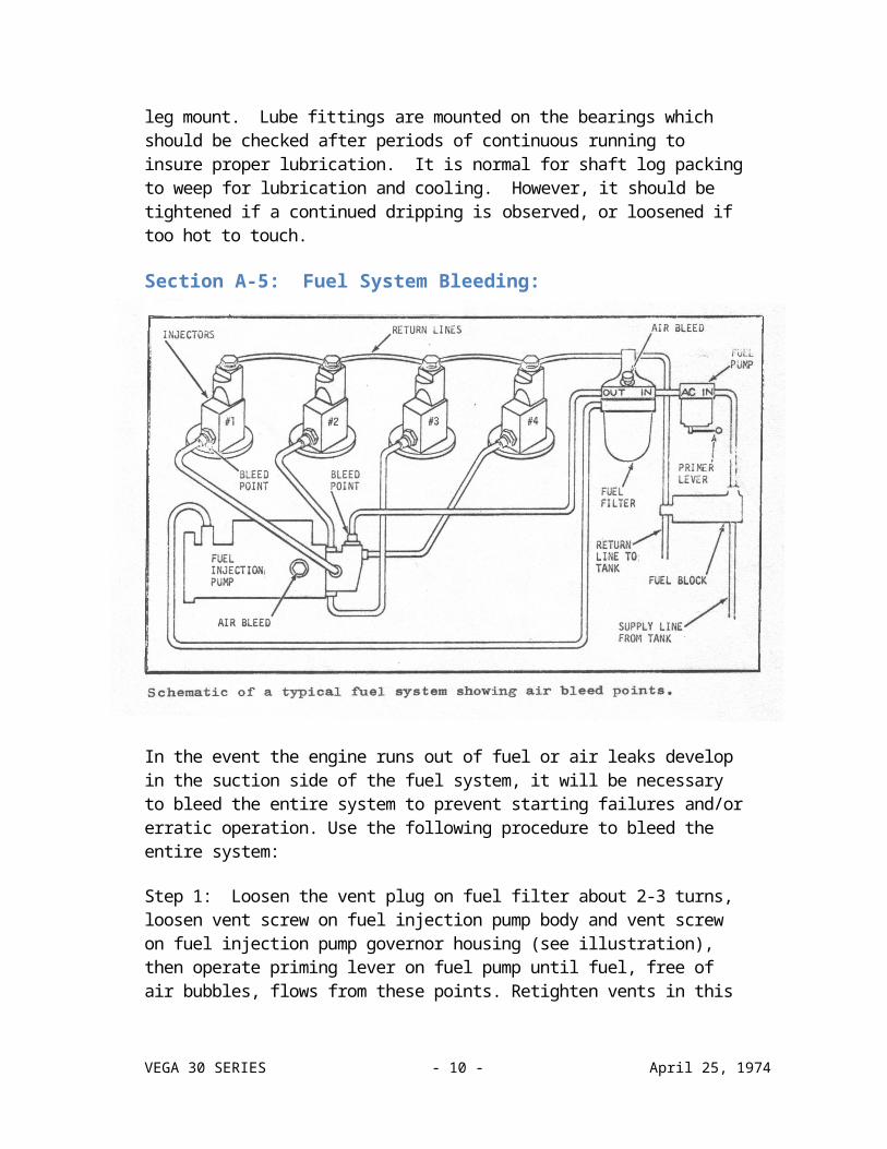
Section A-5: Fuel System Bleeding:
In the event the engine runs out of fuel or air leaks develop in the suction side of the fuel system, it will be necessary to bleed the entire system to prevent starting failures and/or erratic operation. Use the following procedure to bleed the entire system:
Step 1: Loosen the vent plug on fuel filter about 2-3 turns, loosen vent screw on fuel injection pump body and vent screw on fuel injection pump governor housing (see illustration), then operate priming lever on fuel pump until fuel, free of air bubbles, flows from these points. Retighten vents in this order: Filter vent plug, vent on injection pump body and finally vent on governor housing.
Step 2: Loosen the connecting nut on the inlet to the fuel injection pump then operate priming lever on fuel pump until fuel, free of air bubbles, flows out from around the threads. Retighten after air bubbles disappear.
Step 3: Loosen the connecting nuts on the high pressure fuel inlet pipes to each injector then crank engine with starting motor until air bubbles disappear from fuel flowing out of
VEGA 30 SERIES - 9 - April 25, 1974

these connecting points. From 30 to 60 seconds of cranking may be needed to bleed air at these points.
If the engine starts and runs but then stops after a few moments, look for loose connections on the suction side of the system. Bleeding procedure must be repeated if any leakage is discovered. Air in system may cause rough running and excessive noise.
FUEL INJECTORS and fuel injection pump work should be done only by qualified injection service center personnel. Fuel injectors should be removed and serviced after every 500 hours of operation to ensure top performance. It is a good idea to carry extra fuel injectors to replace those being serviced or to replace faulty injectors when underway.
To locate a faulty injector, run the engine at no load then loosen the injector pipe union nut to cut off fuel to each injector in turn until the injector is found which, when cut off, has little or no effect on operation — replace this injector with a spare and check operation.
To replace the injector, disconnect all fittings then remove the injector. Use a new copper washer when installing the replacement injector. Carefully connect piping to make sure pipes are not bent during installation.
SECTION B - CONTROL SYSTEMS
Section B-1: Steering ControlsThe steering control is a mechanical system that consists ofwheel and gear arrangement that activates a push-pull cable attached to the tiller arm on the rudder shaft. These cables are pre-lubricated and completely sealed in sheathing which protects them and preserves lubrication.
An additional safety feature on all boats starting with Hull No. 67 provides an emergency steering tiller. This is found stowed under cockpit seat. Installation procedure is as follows: Step 1: Remove deck plate from cockpit seat above rudder shaft. Step 2: Disconnect steering cable from tiller arm on the rudder shaft by removing clevis pin. Step
VEGA 30 SERIES - 10 - April 25, 1974
3: Socket end of emergency tiller fits onto squared end of rudder shaft above tiller arm.
Section B-2: Rudder InstallationThe rudder foots in a rubber bearing inserted in the bronzeskeg attached to the keel. The skeg also provides bottom protection to the propeller. The rudder shaft penetrates the hull bottom and extends upward through a water tight fiberglass tubeto well above the waterline, then passes through a shaft bearingassembly and terminates above the cockpit sole where the tillerarm is attached. The bearing has a grease fitting which shouldbe lubricated twice a year. It is accessible through the lazarette.
Section B-3: Engine and Shift ControlsThe engine and shift (or throttle and clutch) controls are mechanical push-pull cables similar to steering controls. They are comparatively trouble free and require no maintenance. However, it is recommended that attachment linkage points on the engine be checked periodically to insure they are secure.
SECTION C - ELECTRICAL SYSTEM
Section C-1: Electrical SystemThe wiring diagram in this section must, in some cases, be augmented by the specific engine wiring diagram that appears in the Engine manual. Also note that the description of any special electrical assessory, i.e. electric bilge pump, will be found in another, more appropriate section, yet may appear in this section's wiring diagram or the engine wiring diagram. In the event you make any electrical modifications to your boat, be sure that you follow the WIRING DIAGRAM or consult a competent MARINE ELECTRICIAN. Boat wiring is considerably different from house wiring due to the marine environment and other conditions not associated with houses.
VEGA 30 SERIES - 11 - April 25, 1974
[Note: Electrical Diagram moved to the appendix due to it’s size, 11 x 17”]
Section C-2: Basic Circuit Breaker Electrical SystemThe Master Power Control Panel features integrated, simplified controls and circuit breaker protection to permit safe and efficient operation of your boat's electrical equipment. All panel components have been carefully selected for their proved performance in marine applications. The basic panel is of a metal alloy which is inherently corrosion resistant and is doubly protected to optimize resistance to the effects of the marine environment. Electrical current is directed from two 12-volt, 105 amp batteries through the Master lower Control Panel for engine starting and accessory loads.
Panel selection of "BAT 1" or "BAT 2" determines which of the two batteries will be utilized for engine starting and subsequent charging. Before activating the electrical system, use the Battery Condition Indicator to ascertain the condition of your batteries.
Section C-3: Battery Condition IndicatorThis type of "indicator" or "meter" is technically referred to as a "Suppressed Zero Voltmeter". Note that calibrations do not start at zero, but provide a full scale reading from 8 or 10 to 16-vols, depending on the meter. Below 9 or 10 volts the battery charge is so low that terminal voltage readings are meaningless. Approximate voltage range interpretations are as follows:
Engine NOT ) Below 11 - - - - Very low battery chargeRunning or ) 11 - 12 - - - - Low battery chargeat Idle ) 12 - 1 3 - - - - Well-charged battery
Engine ) 13 - 13½- - - - - Low charge rateRunning ) 13½ - 15½ - - - - Alternator & VoltageAbove ) Regulator OKIdle ) 15½ or above - - Voltage Regulator out of Adjustment
It is important for you to understand that the reading on the Battery Condition Indicator Dial is indexed from the TOGGLE TEST SWITCH POSITION REGARDLESS OF THE MASTER SWITCH POSITION unless it is in the "BOTH" position. When the
VEGA 30 SERIES - 12 - April 25, 1974
Master Switch is in the "BOTH" position then the Battery Condition Indicator Dial will indicate BOTH BATTERY CONDITIONS NO MATTER WHICH WAY THE TOGGLE TEST SWITCH IS INDEXED. When the Master Switch is in either the "OFF", "BAT 1" or "BAT 2" positions, the meter will read the condition of the battery TOWARDS which you index the Toggle Test Switch. Note that panel and meter illumination is also provided by this same Toggle Test Switch.
Before activating the electrical system, check the condition of both batteries and then select the STRONGEST BATTERY FOR ENGINE STARTING. Index the Master Switch to the strong battery, and then start your engine. It will usually require about 15 to 30 minutes of engine running time to bring the starting battery back up to charge. Check the ammeter to assure that charging is normal and when the selected starting battery has been restored it is placed on reserve by switching to the other battery so subsequent charging and accessory loads will be confined to this second battery. It is a good practice to BRING THE FIRST SELECTED BATTERY UP TO FULL CHARGE BEFORE PUTTING IT ON RESERVE AND CHANGING TO THE SECOND BATTERY.
Use the Master Switch in "BOTH" position ONLY for emergencystarting when both batteries are low, or for "top off" chargingwhen both batteries are near full charge. When both batteriesare completely charged, transfer to either battery, keeping onebattery always in reserve. This is especially important when you realize that there is no way to start your inboard engine with a dead battery.
NEVER MOVE THE MASTER SWITCH TO "OFF" WHILE THE ENGINE IS RUNNING OR THE ALTERNATOR DIODES MAY BE BURNED OUT.
Section C-4: Operation of Circuit Breaker Electrical SystemAccessory loads may be selected as desired by indexing the appropriate panel breaker "ON" so current may flow from the switched battery to the accessory. A branch circuit overload will cause the accessory circuit breaker to "trip" i.e., the breaker will automatically open the circuit and its handle will flip to the "OFF" position. After
VEGA 30 SERIES - 13 - April 25, 1974
correction of the fault, the breaker may be manually indexed "ON".
The RUNNING LIGHTS switch activates the red and green lensed side lights, the white stern light aft, and the white bow light forward.
The cabin lights have their own individual switches, but must be activated first by the CABIN LIGHT switch on the Master Power Control Panel. If the cabin lights start getting dim, this is a warning that the battery immediately needs charging, as it probably will not start the engine at this point. For this reason, you should NEVER leave your battery selector switch on "BOTH" when engine is not running or you would have run down both batteries. Remember that you have a wet cell type battery whose charge and water level must be checked at least once a month. If your boat is to be unused or stored for extended periods of time, it is advisable to remove the batteries and store in a warm, dry location.
Periodically check all wires, connections, and terminals for loose connections which may cause loss of ground, sparks, or power loss.
This is especially important with the engine wires. When leaving the boat, INDEX THE MASTER SWITCH TO OFF.
SECTION D - FRESHWATER SYSTEM
Section D-1: Fresh Water SystemTwo (2) standard 50-gallon polyethylene fresh water tanks are located aft under the cockpit sole with a total capacity of 10O-gallons. The Voyager has one (1) 100-gallon polyethylene tank below main cabin sole. Care must be taken so that the air vent is not plugged or it will be impossible to pump water from this tank.
Section D-2: Hot & Cold Pressure Water System with ShowerThe hot water system is operated by either running the engine or on 110-volt AC shore power system through a circuit breaker on the Accessory Control Panel marked "Water Heater". On some water heaters there is also a
VEGA 30 SERIES - 14 - April 25, 1974

switch on unit itself. DO NOT TURN ON UNLESS THERE IS WATER IN THE SYSTEM AS THE HEATING ELEMENT WILL BE BURNED OUT IF THE TANK IS EMPTY.
When filling the system for the first time, or refilling an empty system, you will have to bleed the air out of ALL WATER LINES. This is accomplished in the following manner:
1. Fill water tanks and turn ON ship's electrical system.
2. Turn ON the Pressure Pump by activating the water pressure switch on the Master Power Control Panel.
3. Starting at the galley sink, turn ON the HOT WATER FAUCET. Expect nothing but air for the first few minutes as the hot water heater must be filled before water will flow from the faucet.
4. As the water heater approaches full, water will start to pop and spurt from the faucet. Turn the faucet OFF.
5. Now turn the faucet ON and OFF slowly, with one hand under the spout. This will keep water from splashing about while the last bit of air is being removed from the heater and the galley sink hot water lines.
6. When a solid stream of water is flowing from the spout, turn the faucet OFF. The pressure pump will continue to run and upon reaching about 25 PSI will automatically shut-off.
7. Now repeat this same procedure for the galley sink cold water faucet and both faucets in the head.
8. The system is now completely primed, so top off the water tanks to replace the water that is now in the system.
The pressure pump is a 12-volt DC unit that will start automatically when the pressure drops to 18 PSI and will continue running until the pressure has been brought up to 25 PSI. If the pump starts running wild, you are:
1. Out of water — fill system or switch tanks:
2. Have a leak in lines — check plumbing:
VEGA 30 SERIES - 15 - April 25, 1974
3. Have an air lock — bleed system.
Heat up time with electricity will take about an hour. NOTE that the shower drains into the bilge sump and the BILGE PUMP will operate when the Master Switch and the Accessory Bilge Pump Switch are ON. This will serve as the shower sump pump.
SECTION E – GALLEY EQUIPMENT
Section E-1: The Alcohol Galley RangeYour Vega 3O is equipped with a three-burner alcohol range and oven with stainless steel sea rails. The fuel supply is a two-gallon tank located under the seat locker on the Nomad and on the port side wheelhouse deck on the Searcher and Horizon, and below the galley sink on the Voyager. It contains a large fill opening, valve pressure gauge, and pump.
TO OPERATE STOVE: STARTING: Pump to 10 lbs. air pressure to pressurize tank. The burners must be preheated as follows: Carefully open one burner control at a time, allowing alcohol to flow into the priming cup beneath the burner until cup is about £ filled. DO NOT OVER-FILL! Shut off burner. Light the priming alcohol and wait until consumed: open the control and light the burner. Pre-heated burner produces vaporized alcohol and will ignite like a gas stove burner. An alternate method of preheating is the use of preheating tablets: These will produce a smaller and more concentrated preheating flame. Do not put a cooking utensil over the burner until the burner is operating properly. I LEASE refer to Bulletin contained in Owner's folio for complete operating instructions.
Section E-2: The IceboxYour icebox is insulated with a three-inch, foamed-in-place, layer of polyurethane foam and should retain low temperatures over ex- L tended periods of time. SINCE THE ICEBOX DRAINS INTO THE SUMP IN THE BILGE, IT IS ADVISABLE TO CHECK THE BILGE BEFORE AND AFTER ALL OUTINGS.
In order to get the icebox as large as possible, the lower portion and the drain on some models are BELOW the waterline. Thus, it is not possible to drain to a thru-
VEGA 30 SERIES - 16 - April 25, 1974

hull.Please remember that when a 25 pound block of ice melts, you end up with about three gallons of water in the bilge.
SECTION F - SANITATION SYSTEM - VESSEL WASTES
Section F-1: Marine ToiletThe standard marine toilet installation is a manual operating type that flushes with raw water and pumps overboard. Operating instructions are posted on the unit. Space provisions will accommodate a recirculating toilet or a holding tank and pump-out device, should that be desired or required in your area of operation.
Section F-2: Shower Waste WaterShower water drains to the bilge sump and is discharged overboard by the bilge pump. Care should be taken to assure activation of the bilge pump to prevent build-up of accumulated water in the bilge sump. Lavatory drain is directly overboard.
Section F-3: Galley Waste WaterGalley sink is a direct overboard drain and icebox drain, as noted in proceeding section, is into the bilge.
SECTION G - BILGE SYSTEM
Section G-1: Bilge SystemEvery boat has been equipped with one Manual Bilge Pump and an Electric Bilge Pump.
The factory installed Electric Bilge lump is connected to a switch on your Accessory Control Panel. Some boats are equipped with a MANUAL electric bilge pump, which is activated only by the switch on control panel, and some are equipped to operate AUTOMATICALLY through a float switch when the Control panel switch and the Master Battery switch are on. When water in the bilge sump is high enough to raise the float to two (2) inches, the pump will automatically go on.
A Manual Bilge Pump is located in the lower portion of the
VEGA 30 SERIES - 17 - April 25, 1974

locker in the head on the Horizon and Searcher models and in the aft salon seat locker in the Nomad and Voyager, and discharges out the starboard thru-hull.
SECTION H - TOTAL CARE INFORMATION
Section H-1: Fiberglass SurfacesThe glossy outer surface of your laminated fiberglass boat is known as "gelcoat", a polyester resin into which coloring pigments and weathering retardants have been incorporated. It should be hosed with fresh water after every outing and routinely washed with a good detergent. Use a sponge on the smooth surfaces, while a stiff deck brush will be helpful on the non-skid surfaces, followed by more fresh water to avoid streaking the topsides. Do not use abrasive cleaners as they will rapidly dull the gelcoat surface. A chamois should be used to wipe off smooth surfaces and windows to prevent water spots.
At least once a year (preferably every six months) the smooth gelcoat surfaces should be waxed and polished with a good automotive wax or a boat wax that is especially formulated for fiberglass surfaces. Color in gelcoat, as in any material exposed to direct sunlight, tends to face, dull, or chalk, and may require heavier buffing to bring back the original luster. For power cleaning use a light abrasive cleaner such as Mirror Glaze #1, while a heavier rubbing compound such as DuPont #7 may be used when polishing by hand. After buffing, wax and polish all surfaces EXCEPT the non-skid areas.
Regardless of the amount of care lavished on your boat, occasional scratches, surface checks or cracks, and small gouges are bound to appear. It is best to discuss the proper course of action with your local dealer or a professional who is SKILLED IN THE REPAIR OF FIBERGLASS BOATS.
Section H-2: WoodworkThe exterior and interior trim is teak, one of the most durable and decorative of all hardwoods. Teak must be maintained to keep it from discoloring. A generous coat of "Penta Var Sealer" #ICL 59 has been applied on all the teak at the factory.
VEGA 30 SERIES - 18 - April 25, 1974

Leaving the teak untreated and allowing it to weather naturallycan cause splitting and a poor appearance. Bronze wool or finesandpaper should be used periodically to clean the surface and acommercially available preparation such as Penta Var should beapplied to combat the dull gray appearance of naturally weatheredwood and help eliminate splitting. -
! CAUTION !
Never use steel wool instead of bronze wool or sandpaper. Small filaments of steel break off and cause rust spots that are very difficult to remove.
Another method of treating your exterior teak is varnishing. This method requires quite a bit of maintenance. The natural oils in teak tend to inhibit the bond of the varnish to the wood. If you decide to varnish, be prepared to add at least one additional coat approximately every four months. If the teak has been "oiled", it must be cleaned by scraping and/or heavy sanding with #80 or #100 paper before sealing and varnishing. While the teak still has its original color and texture, smooth with medium grit sandpaper (#129), dust the surface carefully, and seal with a good sealer such as Brolite S-94 Clear Acrylic Sealer. Make sure you select a dry warm day, and do not seal or varnish much after noon as the afternoon dampness will prevent proper drying and cause your varnish job to look discolored and uneven. Allow the sealer to dry at least overnight. Then smooth the raised grain with #120 paper, dust carefully, and apply the first coat of a. good quality spar varnish. The second and third coats are applied with at least a days wait inbetween and will provide a minimum varnish covering for your exterior wood trim. Four or five coats are better, now sanding inbetween with #180 sandpaper. Several thin coats always result in a far superior finish to a lesser number of thicker coats. A good rub with a chamois after hosing down will keep the gloss and also lengthen varnish life.
VEGA 30 SERIES - 19 - April 25, 1974
Section H-3: Interior AppointmentsYou can treat everything below decks just like a home interior. Your interior teak should be oiled occasionally with a quality teak oil such as "Tip Top" to maintain its "yacht like" appearance. Keep the boat well ventilated, especially the bilges and lockers, and watch out for dampness. It's a good idea to leave the bunk cushions on their sides and open up the lockers if you plan to be gone for awhile. It might not look very neat, but it increases ventilation and allows everything to air out. Any time things get wet with salt water, rinse off with FRESH WATER as soon as possible and let dry thoroughly. The salt crystals retain moisture and the material will always remain damp until cleaned with fresh water. Air and sunlight are wonderful cleaners! Bring the vacuum cleaner aboard and get the carpet, cushions, blankets, sleeping bags, etc., up on deck in the sunshine while the vacuum picks up below. Spring cleaning should take place periodically, not annually, to keep the interior clean and bright.
Most of the equipment below deck is covered in other sections of the manual, with the exception of any other accessories that you have installed.
Section H-4: Spars, Rigging, and HardwareThe surface of your ALUMINUM SPARS on the Horizon Vega 30 is protected from corrosion by a natural film of aluminum oxide. Unfortunately, in time dirt, salt, and chemical contaminants will break through this natural protective film, causing it to appear grimy and unsightly. To prevent adherence of these materials, coat the surface of your spars with a good automotive paste wax or a commercial protective coating. Brolite Z-Spar #100 Gloss White Enamel is used on the factory painted wooden spars. It consists of a prime coat, two undercoats, and a gloss coat. This product is compatible with other paints if touch-up is required. A good hosing with fresh water helps. ALWAYS keep halyards tied away from the mast. Besides protecting the aluminum oxide or painted surface, it does away with the din created by halyards slapping against the mast.
Periodically take a trip aloft to check the entire rig. Perhaps it would be less difficult to simply lower the
VEGA 30 SERIES - 20 - April 25, 1974
mast. Look for signs of chafe and check all nuts, bolts, screws, cotter keys, blocks, and masthead sheaves. Make sure the spreader tips are well covered with tape or leather to protect the sails from chafe and tearing. Take along a rag and bucket of fresh water to clean the rigging and mast on your way up. A clean rig means clean sails! On your way down, re-apply whatever protective coating you have decided to use on the mast and your work aloft is done — until the next time!
The halyards, sheets, and guys, along with all rope and wire splices, should be carefully checked before and after each sail for wear. Wire rigging must be examined for broken strands and signs of frayed sections.
Particularly close scrutiny should be given to those sections which rest on sheaves. The lines supplied with your boat are Dacron, have little stretch, and wear very well if not abused. Sheets and vangs often lead where they will rub together or chafe on lifelines. By adjusting leads or by applying inexpensive chafing gear, expensive damage may be prevented. When not in use, running rigging should be tied away from the mast or neatly coiled and hung in regular locations where it can be readily found. Frayed ends should be burned and whipped while chafed eye splices may be respliced following the instructions available from Samson Cordage Works, 470 Atlantic Avenue, Boston, Massachusetts 02210. All blocks, sheaves, turnbuckles, and winches used in conjunction with running rigging should be lubricated periodically with a light grease such as "Lubriplate" or sprayed with a protective film such as "WD-40".
Why is my stainless steel rusting? Basically, it is a galvanic action and you can prevent it with a cleaning rag! If you keep the stainless hardware on your boat free of marine growth and polished, it will last longer and look better. Saltwater sailers must hose off with fresh water after a hard, wet run, and a rub down with a chamois always helps. For a complete explanation on stainless steel in non-technical language, read John Fisher's excellent article in the January 1972 Boating Magazine.
VEGA 30 SERIES - 21 - April 25, 1974
SECTION I - SUGGESTED ONBOARD SPARE PARTS
Section I-1: Engine & Fuel System Refer to attached.
Section I-2: ElectricalInterior Light Fixtures - 12-v 25-w standard base bulbs
Running Lights - GE 1004 Bulbs
Section I-3: Water SystemsPressure pump - Jabsco Part No. 6800 J
Drive Belt for above - Jabsco Part No. ^5^3
Bilge Pump - Jabsco "Water Puppy" Part No. 6360
Empeller for Jabsco "Water Puppy" Part No. 6303-37
VEGA 30 SERIES - 22 - April 25, 1974

PERKINS 4.107MS - SUGGESTED MINOR ON BOARD SPARE PARTS:
VEGA 30 SERIES - 23 - April 25, 1974
VEGA 30 – MECHANICAL MAINTENANCE CHECK LIST
VEGA 30 SERIES - 24 - April 25, 1974