Embed Size (px)
Citation preview
TM
OWNER’S OPERATION
ANDMAINTENANCE MANUAL
OF THEMAK SPUTTERING SOURCES
6280 San Ignacio Avenue, Suite ESan Jose, CA 95119-1365
PH: (408) 363.6909 FX: (408) 363.6996 E-MAIL: [email protected]
YOUR S/N _____________________________
WARNING
AS WITH ALL ELECTRICAL DEVICES, THERE IS A SHOCK HAZARDASSOCIATED WITH THIS DEVICE. ALL INSTRUCTIONS SHOULD BEFOLLOWED PERTAINING TO THE USE OF SUITABLE INTERLOCKS ON ALLPOWER SUPPLIES TO BE USED TO POWER THIS PRODUCT.
2
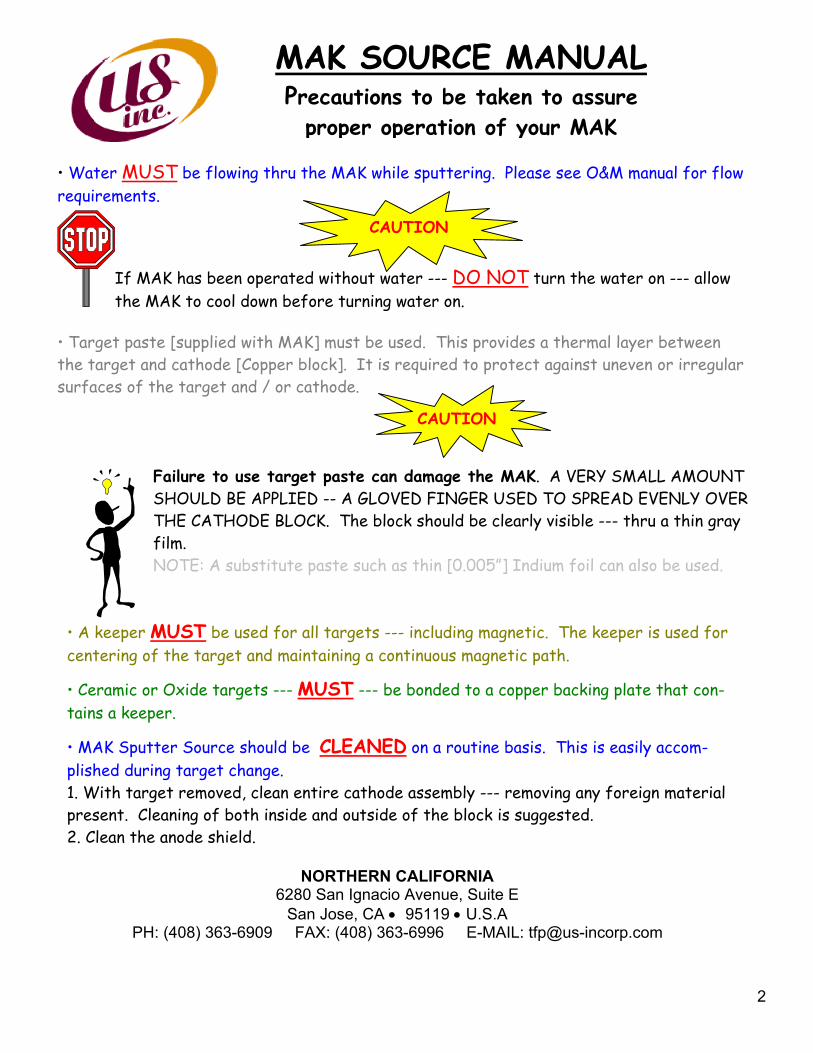
Failure to use target paste can damage the MAK. A VERY SMALL AMOUNTSHOULD BE APPLIED -- A GLOVED FINGER USED TO SPREAD EVENLY OVERTHE CATHODE BLOCK. The block should be clearly visible --- thru a thin grayfilm.NOTE: A substitute paste such as thin [0.005”] Indium foil can also be used.
• Ceramic or Oxide targets --- MUST --- be bonded to a copper backing plate that con-tains a keeper.
• MAK Sputter Source should be CLEANED on a routine basis. This is easily accom-plished during target change.1. With target removed, clean entire cathode assembly --- removing any foreign materialpresent. Cleaning of both inside and outside of the block is suggested.2. Clean the anode shield.
• A keeper MUST be used for all targets --- including magnetic. The keeper is used forcentering of the target and maintaining a continuous magnetic path.
CAUTION
• Water MUST be flowing thru the MAK while sputtering. Please see O&M manual for flowrequirements.
If MAK has been operated without water --- DO NOT turn the water on --- allowthe MAK to cool down before turning water on.
MAK SOURCE MANUALPrecautions to be taken to assure
proper operation of your MAK
• Target paste [supplied with MAK] must be used. This provides a thermal layer betweenthe target and cathode [Copper block]. It is required to protect against uneven or irregularsurfaces of the target and / or cathode.
CAUTION
NORTHERN CALIFORNIA6280 San Ignacio Avenue, Suite E
San Jose, CA • 95119 • U.S.APH: (408) 363-6909 FAX: (408) 363-6996 E-MAIL: [email protected]
3
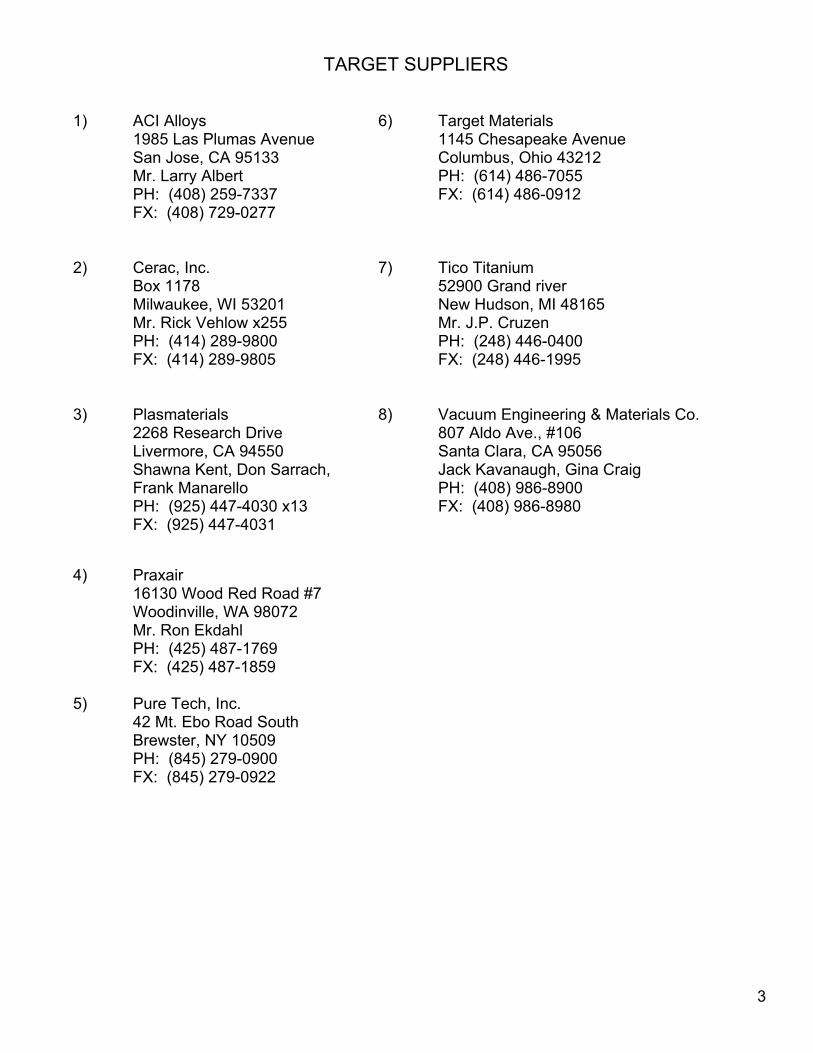
TARGET SUPPLIERS
1) ACI Alloys1985 Las Plumas AvenueSan Jose, CA 95133Mr. Larry AlbertPH: (408) 259-7337FX: (408) 729-0277
6) Target Materials1145 Chesapeake AvenueColumbus, Ohio 43212PH: (614) 486-7055FX: (614) 486-0912
2) Cerac, Inc.Box 1178Milwaukee, WI 53201Mr. Rick Vehlow x255PH: (414) 289-9800FX: (414) 289-9805
7) Tico Titanium52900 Grand riverNew Hudson, MI 48165Mr. J.P. CruzenPH: (248) 446-0400FX: (248) 446-1995
3) Plasmaterials2268 Research DriveLivermore, CA 94550Shawna Kent, Don Sarrach,Frank ManarelloPH: (925) 447-4030 x13FX: (925) 447-4031
8) Vacuum Engineering & Materials Co.807 Aldo Ave., #106Santa Clara, CA 95056Jack Kavanaugh, Gina CraigPH: (408) 986-8900FX: (408) 986-8980
4) Praxair16130 Wood Red Road #7Woodinville, WA 98072Mr. Ron EkdahlPH: (425) 487-1769FX: (425) 487-1859
5) Pure Tech, Inc.42 Mt. Ebo Road SouthBrewster, NY 10509PH: (845) 279-0900FX: (845) 279-0922
4
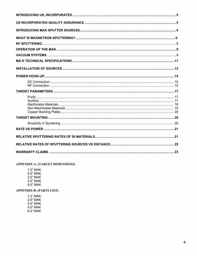
INTRODUCING US, INCORPORATED ....................................................................................................................5
US INCORPORATED QUALITY ASSURANCE .......................................................................................................5
INTRODUCING MAK SPUTTER SOURCES............................................................................................................5
WHAT IS MAGNETRON SPUTTERING?................................................................................................................6 RF SPUTTERING ......................................................................................................................................................8
OPERATION OF THE MAK ......................................................................................................................................9VACUUM SYSTEMS .................................................................................................................................................9
MA K TECHNICAL SPECIFICATIONS...................................................................................................................11
INSTALLATION OF SOURCES..............................................................................................................................13
POWER HOOK-UP..................................................................................................................................................15DC Connection............................................................................................................................................15RF Connection ............................................................................................................................................15
TARGET PARAMETERS ........................................................................................................................................17Purity ...........................................................................................................................................................17Surface ........................................................................................................................................................17Machinable Materials ..................................................................................................................................18Non-Machinable Materials ..........................................................................................................................19Copper Backing Plates................................................................................................................................20
TARGET MOUNTING..............................................................................................................................................20Simplicity in Sputtering................................................................................................................................20
RATE VS POWER ...................................................................................................................................................21
RELATIVE SPUTTERING RATES OF 50 MATERIALS.........................................................................................21
RELATIVE RATES OF SPUTTERING SOURCES VS DISTANCE........................................................................22
WARRANTY CLAIMS .............................................................................................................................................23
APPENDIX A: (TARGET DIMENSIONS)
1.3” MAK2.0” MAK3.0” MAK4.0” MAK6.0” MAK
APPENDIX B: (PARTS LIST)
1.3” MAK2.0” MAK3.0” MAK4.0” MAK6.0” MAK
5
INTRODUCING US, INCORPORATEDUS, Incorporated has been an innovative manufacturer and sales organization of thin film and highvacuum equipment since 1977. Exclusive licenses were obtained from Stanford University andLawrence Livermore Laboratory to build and distribute their patented magnetron sputtering sourceson a worldwide basis.
US INCORPORATED QUALITY ASSURANCEAll US, Incorporated products are manufactured under the most stringent conditions. This includesproper selection & inspection of original materials, assembly in clean room conditions, and com-plete testing for leaks & functionality. These quality products are packaged in durable containersfor shipment throughout the world.
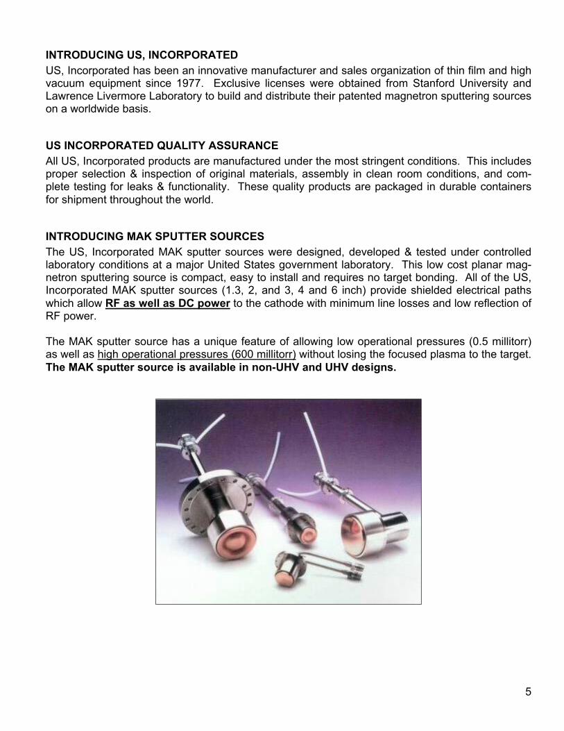
INTRODUCING MAK SPUTTER SOURCESThe US, Incorporated MAK sputter sources were designed, developed & tested under controlledlaboratory conditions at a major United States government laboratory. This low cost planar mag-netron sputtering source is compact, easy to install and requires no target bonding. All of the US,Incorporated MAK sputter sources (1.3, 2, and 3, 4 and 6 inch) provide shielded electrical pathswhich allow RF as well as DC power to the cathode with minimum line losses and low reflection ofRF power.
The MAK sputter source has a unique feature of allowing low operational pressures (0.5 millitorr)as well as high operational pressures (600 millitorr) without losing the focused plasma to the target.The MAK sputter source is available in non-UHV and UHV designs.
6
WHAT IS MAGNETRON SPUTTERING?
Observations of the phenomenon we now call sputtering, go back over one hundred years to earlyexperiments which introduced electricity into a reduced pressure atmosphere. L. Holland de-scribes these beginnings in his book Vacuum Deposition of Thin Films.
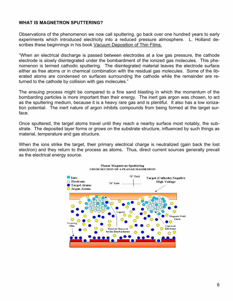
“When an electrical discharge is passed between electrodes at a low gas pressure, the cathodeelectrode is slowly disintegrated under the bombardment of the ionized gas molecules. This phe-nomenon is termed cathodic sputtering. The disintegrated material leaves the electrode surfaceeither as free atoms or in chemical combination with the residual gas molecules. Some of the lib-erated atoms are condensed on surfaces surrounding the cathode while the remainder are re-turned to the cathode by collision with gas molecules.”
The ensuing process might be compared to a fine sand blasting in which the momentum of thebombarding particles is more important than their energy. The inert gas argon was chosen, to actas the sputtering medium, because it is a heavy rare gas and is plentiful. It also has a low ioniza-tion potential. The inert nature of argon inhibits compounds from being formed at the target sur-face.
Once sputtered, the target atoms travel until they reach a nearby surface most notably, the sub-strate. The deposited layer forms or grows on the substrate structure, influenced by such things asmaterial, temperature and gas structure.
When the ions strike the target, their primary electrical charge is neutralized (gain back the lostelectron) and they return to the process as atoms. Thus, direct current sources generally prevailas the electrical energy source.
7
In order to increase sputtering rate, magnetic coils were sometimes placed around the chamber topinch the plasma during the deposition. The pressure was reduced to 20 microns (2 X 10⁻² torr)and the rates increased. The electrodes were close together and the R.F. voltage was high.These conditions caused damage to semiconductor devices due to the high electron and secon-dary ion bombardment, which took place.
When it was realized how important the role of a magnetic field was in concentrating the plasmaand the effects that it had on rate, sputtering became more attractive as a commercial process.Several magnetic configurations were used such as the post cathode, magnetically enhanced hol-low cathodes and magnetrons. In order to make a magnetron work, it is necessary to cause the EX B drift currents to close on themselves. This realization led to the magnetron cathode designsthat are in use today.
MAK BENEFITS
Magnetics
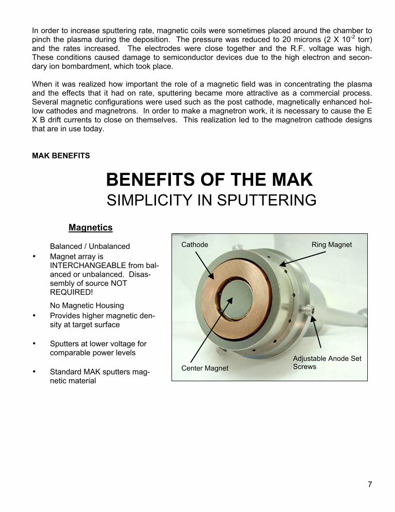
No Magnetic Housing• Provides higher magnetic den-
sity at target surface
• Sputters at lower voltage forcomparable power levels
• Standard MAK sputters mag-netic material
Balanced / Unbalanced• Magnet array is
INTERCHANGEABLE from bal-anced or unbalanced. Disas-sembly of source NOTREQUIRED!
BENEFITS OF THE MAKSIMPLICITY IN SPUTTERING
Cathode Ring Magnet
Center MagnetAdjustable Anode SetScrews
8
RF SPUTTERING If the target is an insulator, the neutralization process results in a positive charge on the targetsurface. This charge may grow to the point that the bombarding ions (±) are repelled and thesputtering process will stop. In order to make the process continue the polarity of the target mustbe reversed to attract enough electrons from the discharge to eliminate the surface charge. In or-der to attract the electrons and not repeal the ions, the frequency must be high enough to reversebefore the direction of the ions are affected. The usual industrial frequency assigned by the FCCfor such is in the MHz range. Since this is a “radio” frequency, the process is called radio fre-quency sputtering, or RF sputtering. Most of the early sputtering was done using direct currentsources. This meant high voltage, with current drawn being limited by the gas pressure. Typicalvoltages were 3-5 kV with a current from 50-250 ma at pressures of 50-250 microns. R.F. powerwas introduced because it makes it possible to sputter insulators.
PICTURE SHOWN IS NOTTO SCALE
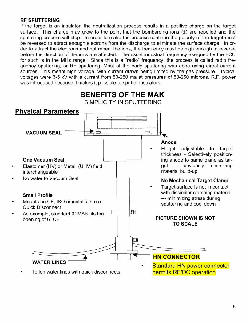
Anode• Height adjustable to target
thickness - Selectively position-ing anode to same plane as tar-get --- obviously minimizingmaterial build-up
No Mechanical Target Clamp• Target surface is not in contact
with dissimilar clamping material--- minimizing stress duringsputtering and cool down
• Standard HN power connectorpermits RF/DC operation
HN CONNECTOR
BENEFITS OF THE MAK SIMPLICITY IN SPUTTERING
Small Profile• Mounts on CF, ISO or installs thru a
Quick Disconnect• As example, standard 3” MAK fits thru
opening of 6” CF
One Vacuum Seal• Elastomer (HV) or Metal (UHV) field
interchangeable• No water to Vacuum Seal
VACUUM SEAL
WATER LINES
• Teflon water lines with quick disconnects
Physical Parameters
9
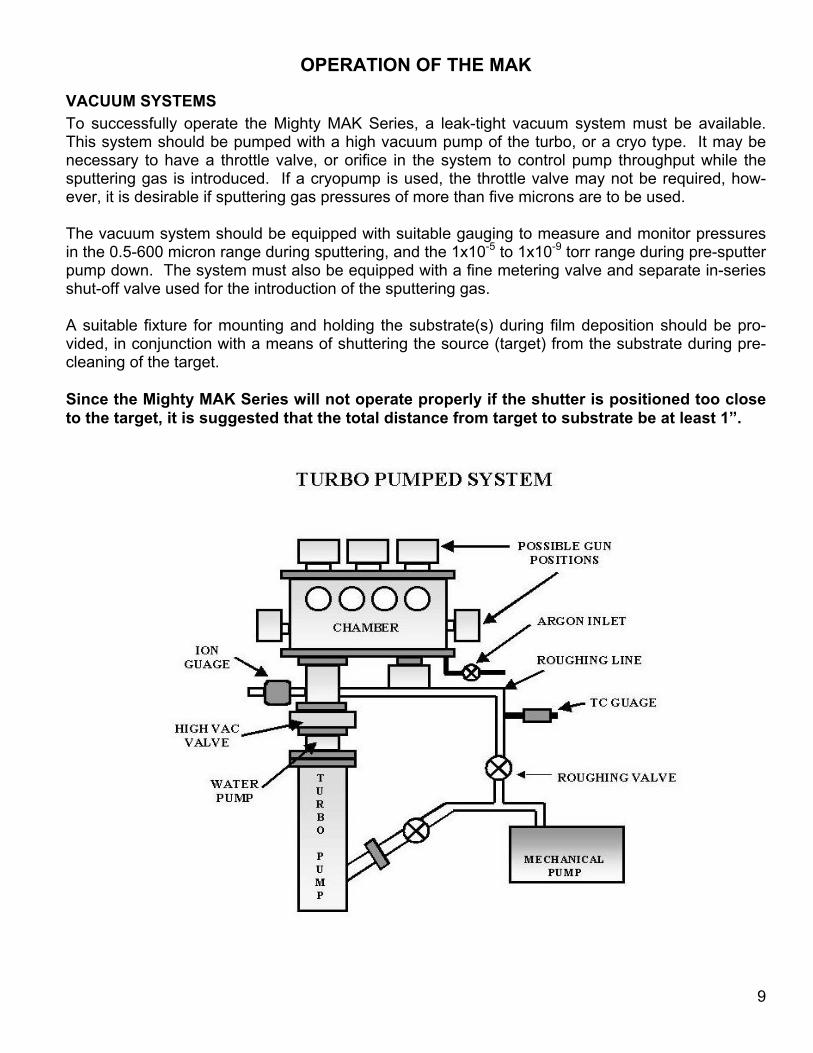
OPERATION OF THE MAK
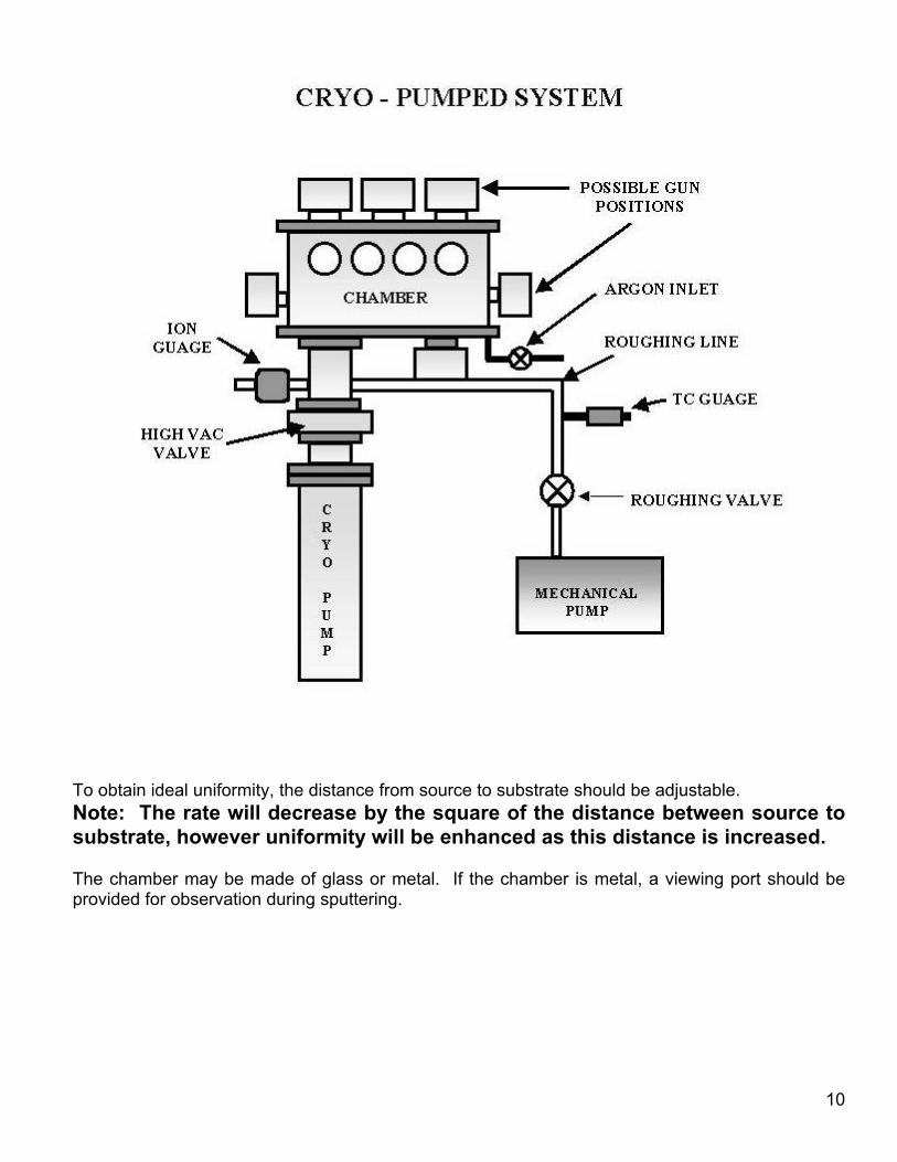
VACUUM SYSTEMSTo successfully operate the Mighty MAK Series, a leak-tight vacuum system must be available.This system should be pumped with a high vacuum pump of the turbo, or a cryo type. It may benecessary to have a throttle valve, or orifice in the system to control pump throughput while thesputtering gas is introduced. If a cryopump is used, the throttle valve may not be required, how-ever, it is desirable if sputtering gas pressures of more than five microns are to be used.
The vacuum system should be equipped with suitable gauging to measure and monitor pressuresin the 0.5-600 micron range during sputtering, and the 1x10⁻⁵ to 1x10⁻⁹ torr range during pre-sputterpump down. The system must also be equipped with a fine metering valve and separate in-seriesshut-off valve used for the introduction of the sputtering gas.
A suitable fixture for mounting and holding the substrate(s) during film deposition should be pro-vided, in conjunction with a means of shuttering the source (target) from the substrate during pre-cleaning of the target.
Since the Mighty MAK Series will not operate properly if the shutter is positioned too closeto the target, it is suggested that the total distance from target to substrate be at least 1”.
10
To obtain ideal uniformity, the distance from source to substrate should be adjustable. Note: The rate will decrease by the square of the distance between source tosubstrate, however uniformity will be enhanced as this distance is increased.
The chamber may be made of glass or metal. If the chamber is metal, a viewing port should beprovided for observation during sputtering.
11
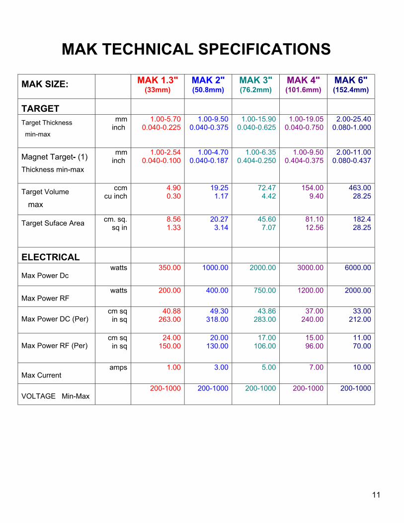
MAK TECHNICAL SPECIFICATIONS
MAK SIZE: MAK 1.3"(33mm)
MAK 2"(50.8mm)
MAK 3"(76.2mm)
MAK 4"(101.6mm)
MAK 6"(152.4mm)
TARGETTarget Thickness
min-max
mminch
1.00-5.700.040-0.225
1.00-9.500.040-0.375
1.00-15.900.040-0.625
1.00-19.050.040-0.750
2.00-25.400.080-1.000
Magnet Target- (1)Thickness min-max
mminch
1.00-2.540.040-0.100
1.00-4.700.040-0.187
1.00-6.350.404-0.250
1.00-9.500.404-0.375
2.00-11.000.080-0.437
Target Volume
max
ccmcu inch
4.900.30
19.251.17
72.474.42
154.009.40
463.0028.25
Target Suface Area cm. sq.sq in
8.561.33
20.273.14
45.607.07
81.1012.56
182.428.25
ELECTRICAL
Max Power Dc watts 350.00 1000.00 2000.00 3000.00 6000.00
Max Power RFwatts 200.00 400.00 750.00 1200.00 2000.00
Max Power DC (Per) cm sqin sq
40.88263.00
49.30318.00
43.86283.00
37.00240.00
33.00212.00
Max Power RF (Per)cm sqin sq
24.00150.00
20.00130.00
17.00106.00
15.0096.00
11.0070.00
Max Current amps 1.00 3.00 5.00 7.00 10.00
VOLTAGE Min-Max200-1000 200-1000 200-1000 200-1000 200-1000
12
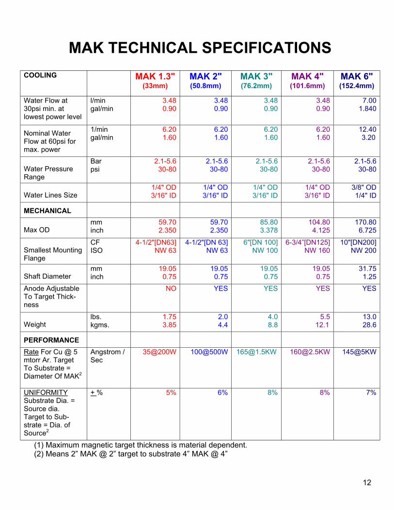
MAK TECHNICAL SPECIFICATIONSCOOLING MAK 1.3"
(33mm)MAK 2"(50.8mm)
MAK 3"(76.2mm)
MAK 4"(101.6mm)
MAK 6"(152.4mm)
Water Flow at30psi min. atlowest power level
l/mingal/min
3.480.90
3.480.90
3.480.90
3.480.90
7.001.840
Nominal WaterFlow at 60psi formax. power
1/mingal/min
6.201.60
6.201.60
6.201.60
6.201.60
12.40 3.20
Water PressureRange
Barpsi
2.1-5.630-80
2.1-5.630-80
2.1-5.630-80
2.1-5.630-80
2.1-5.630-80
Water Lines Size1/4" OD3/16" ID
1/4" OD3/16" ID
1/4" OD3/16" ID
1/4" OD3/16" ID
3/8" OD1/4" ID
MECHANICAL
Max ODmminch
59.702.350
59.702.350
85.803.378
104.804.125
170.806.725
Smallest MountingFlange
CFISO
4-1/2"[DN63]NW 63
4-1/2"[DN 63]NW 63
6"[DN 100] NW 100
6-3/4”[DN125] NW 160
10"[DN200]NW 200
Shaft Diametermminch
19.050.75
19.050.75
19.050.75
19.050.75
31.751.25
Anode AdjustableTo Target Thick-ness
NO YES YES YES YES
Weightlbs.kgms.
1.753.85
2.04.4
4.08.8
5.5 12.1
13.028.6
PERFORMANCERate For Cu @ 5mtorr Ar. TargetTo Substrate =Diameter Of MAK2
Angstrom /Sec
35@200W 100@500W [email protected] [email protected] 145@5KW
UNIFORMITYSubstrate Dia. =Source dia. Target to Sub-strate = Dia. ofSource2
+ % 5% 6% 8% 8% 7%
(1) Maximum magnetic target thickness is material dependent. (2) Means 2” MAK @ 2” target to substrate 4” MAK @ 4”
13
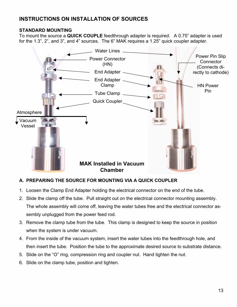
INSTRUCTIONS ON INSTALLATION OF SOURCES
STANDARD MOUNTINGTo mount the source a QUICK COUPLE feedthrough adapter is required. A 0.75” adapter is usedfor the 1.3”, 2”, and 3”, and 4” sources. The 6” MAK requires a 1.25” quick coupler adapter.
A. PREPARING THE SOURCE FOR MOUNTING VIA A QUICK COUPLER
1. Loosen the Clamp End Adapter holding the electrical connector on the end of the tube.
2. Slide the clamp off the tube. Pull straight out on the electrical connector mounting assembly.
The whole assembly will come off, leaving the water tubes free and the electrical connector as-
sembly unplugged from the power feed rod.
3. Remove the clamp tube from the tube. This clamp is designed to keep the source in position
when the system is under vacuum.
4. From the inside of the vacuum system, insert the water tubes into the feedthrough hole, and
then insert the tube. Position the tube to the approximate desired source to substrate distance.
5. Slide on the “O” ring, compression ring and coupler nut. Hand tighten the nut.
6. Slide on the clamp tube, position and tighten.
MAK Installed in VacuumChamber
Water Lines
Tube Clamp
End AdapterClamp HN Power
Pin
End Adapter
Quick Coupler
Power Connector(HN)
Power Pin SlipConnector
(Connects di-rectly to cathode)
VacuumVessel
Atmosphere
14
7. Put the Clamp End Adapter on the tube and then assemble the electrical connector. Make sure
that the slip pin in the connector body is inserted in the socket of the power feed rod. Push on
as far as it will go and slide the Clamp end Adapter on and tighten.
8. The system may now be pumped down.
9. Hook up the water lines. Connect the house supply and drain lines to the source tubes. See
technical specifications for minimum flow requirements.
10. Connect the power cable.
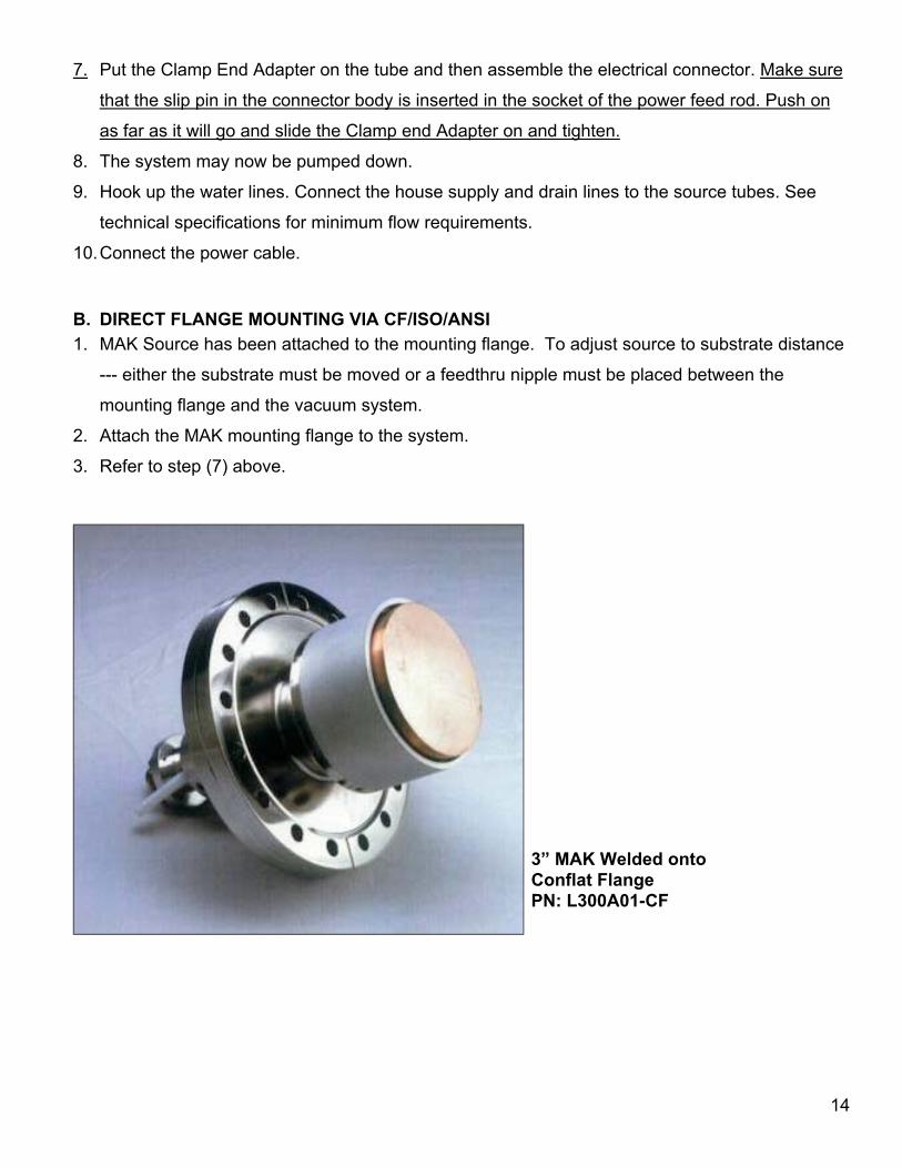
B. DIRECT FLANGE MOUNTING VIA CF/ISO/ANSI1. MAK Source has been attached to the mounting flange. To adjust source to substrate distance
--- either the substrate must be moved or a feedthru nipple must be placed between the
mounting flange and the vacuum system.
2. Attach the MAK mounting flange to the system.
3. Refer to step (7) above.
3” MAK Welded ontoConflat FlangePN: L300A01-CF
15
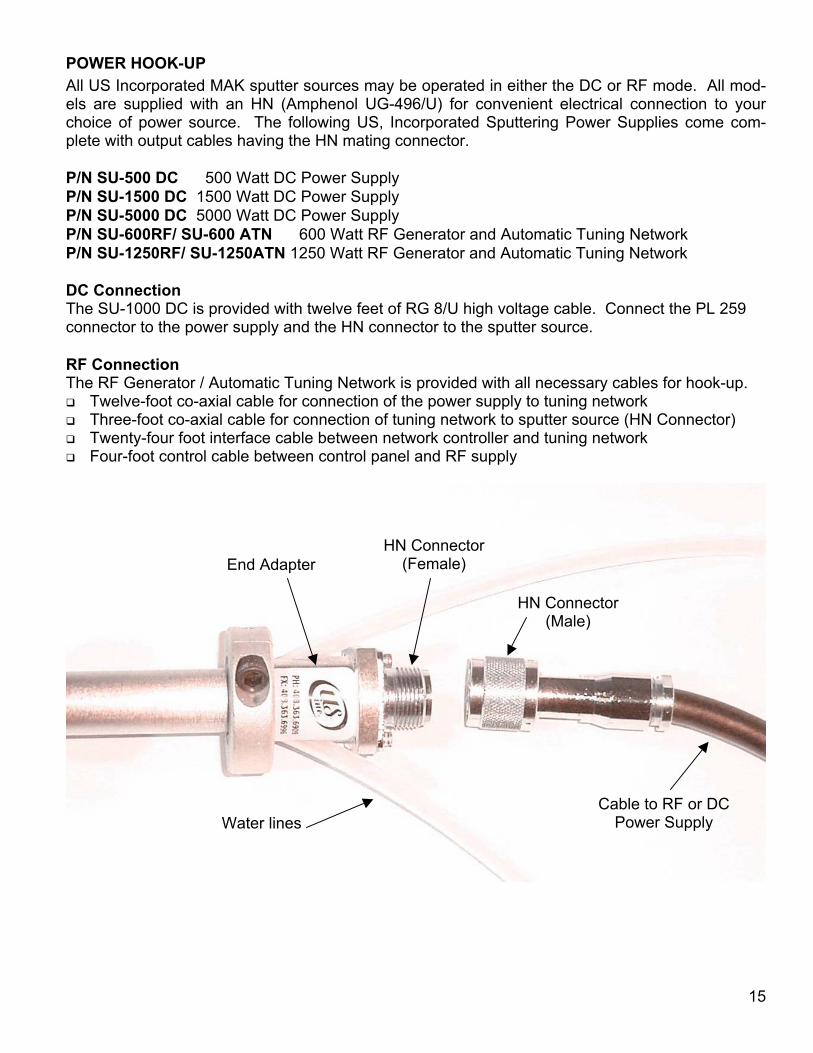
POWER HOOK-UPAll US Incorporated MAK sputter sources may be operated in either the DC or RF mode. All mod-els are supplied with an HN (Amphenol UG-496/U) for convenient electrical connection to yourchoice of power source. The following US, Incorporated Sputtering Power Supplies come com-plete with output cables having the HN mating connector.
P/N SU-500 DC 500 Watt DC Power SupplyP/N SU-1500 DC 1500 Watt DC Power Supply P/N SU-5000 DC 5000 Watt DC Power SupplyP/N SU-600RF/ SU-600 ATN 600 Watt RF Generator and Automatic Tuning NetworkP/N SU-1250RF/ SU-1250ATN 1250 Watt RF Generator and Automatic Tuning Network
DC ConnectionThe SU-1000 DC is provided with twelve feet of RG 8/U high voltage cable. Connect the PL 259connector to the power supply and the HN connector to the sputter source.
RF ConnectionThe RF Generator / Automatic Tuning Network is provided with all necessary cables for hook-up.
Twelve-foot co-axial cable for connection of the power supply to tuning network Three-foot co-axial cable for connection of tuning network to sputter source (HN Connector) Twenty-four foot interface cable between network controller and tuning network Four-foot control cable between control panel and RF supply
HN Connector(Male)
End Adapter
Water lines
HN Connector(Female)
Cable to RF or DCPower Supply
16
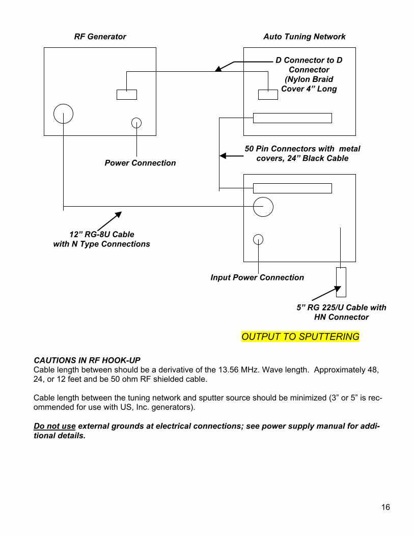
CAUTIONS IN RF HOOK-UPCable length between should be a derivative of the 13.56 MHz. Wave length. Approximately 48,24, or 12 feet and be 50 ohm RF shielded cable.
Cable length between the tuning network and sputter source should be minimized (3” or 5” is rec-ommended for use with US, Inc. generators).
Do not use external grounds at electrical connections; see power supply manual for addi-tional details.
12” RG-8U Cablewith N Type Connections
RF Generator
D Connector to DConnector
(Nylon BraidCover 4” Long
50 Pin Connectors with metalcovers, 24” Black CablePower Connection
Input Power Connection
5” RG 225/U Cable withHN Connector
OUTPUT TO SPUTTERING
Auto Tuning Network
17
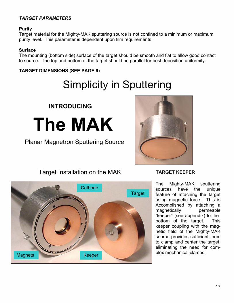
TARGET PARAMETERS
PurityTarget material for the Mighty-MAK sputtering source is not confined to a minimum or maximumpurity level. This parameter is dependent upon film requirements.
SurfaceThe mounting (bottom side) surface of the target should be smooth and flat to allow good contactto source. The top and bottom of the target should be parallel for best deposition uniformity.
TARGET DIMENSIONS (SEE PAGE 9)
TARGET KEEPER
The Mighty-MAK sputteringsources have the uniquefeature of attaching the targetusing magnetic force. This isAccomplished by attaching amagnetically permeable“keeper” (see appendix) to the bottom of the target. Thiskeeper coupling with the mag-netic field of the Mighty-MAKsource provides sufficient forceto clamp and center the target,eliminating the need for com-plex mechanical clamps.
Simplicity in Sputtering
INTRODUCING
Planar Magnetron Sputtering Source
The MAK
Target
Keeper
Cathode
Magnets
Target Installation on the MAK
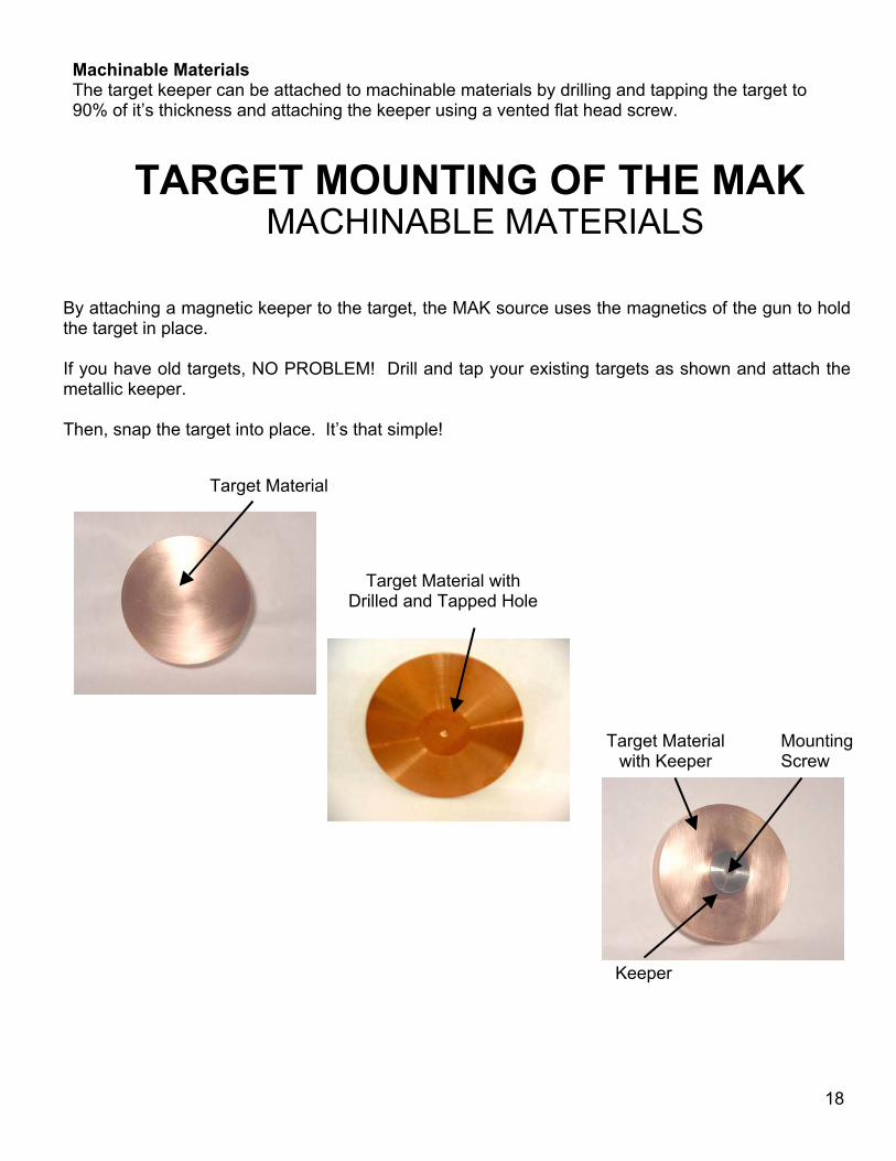
Machinable MaterialsThe target keeper can be attached to machinable materials by drilling and tapping the target to90% of it’s thickness and attaching the keeper using a vented flat head screw.
Target
By attaching a magnetic the target in place.
If you have old targets, Nmetallic keeper.
Then, snap the target into
TARGET MOUNTING OF THE MAK
MACHINABLE MATERIALS18
Material
keeper to the target, the MAK source uses the magnetics of the gun to hold
O PROBLEM! Drill and tap your existing targets as shown and attach the
place. It’s that simple!
Target Material withDrilled and Tapped Hole
Keeper
Target Materialwith Keeper
MountingScrew
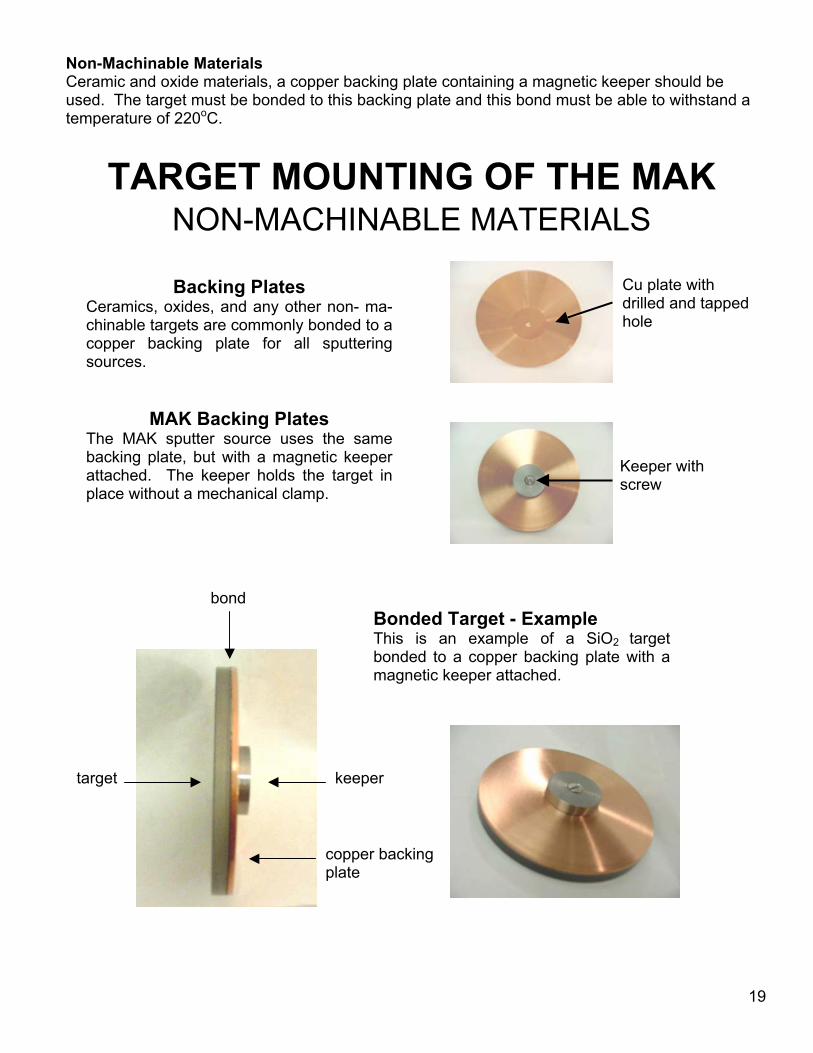
Non-Machinable MaterialsCeramic and oxide materials, a copper backing plate containing a magnetic keeper should beused. The target must be bonded to this backing plate and this bond must be able to withstand atemperature of 220oC.
Backing PlatesCeramics, oxides, and any other non- ma-chinable targets are commonly bonded to acopper backing plate for all sputteringsources.
MAK Backing PlatesThe MAK sputter source uses the samebacking plate, but with a magnetic keeperattached. The keeper holds the target inplace without a mechanical clamp.
TARGET MOUNTING OF THE MAKNON-MACHINABLE MATERIALS
Cu plate withdrilled and tappedhole
Keeper withscrew
target
bond
19
Bonded Target - ExampleThis is an example of a SiO2 targetbonded to a copper backing plate with amagnetic keeper attached.
keeper
copper backingplate
20
Copper Backing Plate Specifications (See Appendix A)MAK 1.3” Copper Backing Plate Part Number: MAK-130-BP
MAK 2” Copper Backing Plate Part Number MAK-200-BP
MAK 3” Copper Backing Plate Part Number MAK-300-BP
MAK 4” Copper Backing Plate Part Number MAK-400-BP
MAK 6” Copper Backing Plate Part Number MAK-600-BP
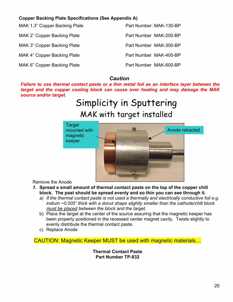
CautionFailure to use thermal contact paste or a thin metal foil as an interface layer between thetarget and the copper cooling block can cause over heating and may damage the MAKsource and/or target.
Remove the Anode1. Spread a small amount of thermal contact paste on the top of the copper chill
block. The past should be spread evenly and so thin you can see through it.a) If the thermal contact paste is not used a thermally and electrically conductive foil e.g.
indium ~0.005” thick with a donut shape slightly smaller than the cathode/chill blockmust be placed between the block and the target.
b) Place the target at the center of the source assuring that the magnetic keeper hasbeen properly positioned in the recessed center magnet cavity. Twists slightly toevenly distribute the thermal contact paste.
c) Replace Anode
CAUTION: Magnetic Keeper MUST be used with magnetic materials…
Thermal Contact PastePart Number TP-832
Simplicity in SputteringMAK with target installed
Targetmounted withmagnetickeeper
Anode retracted
21
COPPER 2"D, 3" DIST.
0.005.00
10.0015.0020.0025.0030.0035.0040.00
0 50 100 150 200 250 300 350 400 450 500
Watts RF
A/sec
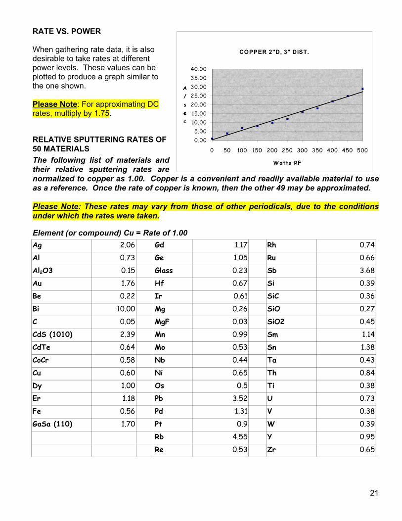
RATE VS. POWER
When gathering rate data, it is alsodesirable to take rates at differentpower levels. These values can beplotted to produce a graph similar tothe one shown.
Please Note: For approximating DCrates, multiply by 1.75.
RELATIVE SPUTTERING RATES OF50 MATERIALSThe following list of materials andtheir relative sputtering rates arenormalized to copper as 1.00. Copper is a convenient and readily available material to useas a reference. Once the rate of copper is known, then the other 49 may be approximated.
Please Note: These rates may vary from those of other periodicals, due to the conditionsunder which the rates were taken.
Element (or compound) Cu = Rate of 1.00Ag 2.06 Gd 1.17 Rh 0.74
Al 0.73 Ge 1.05 Ru 0.66
Al2O3 0.15 Glass 0.23 Sb 3.68
Au 1.76 Hf 0.67 Si 0.39
Be 0.22 Ir 0.61 SiC 0.36
Bi 10.00 Mg 0.26 SiO 0.27
C 0.05 MgF 0.03 SiO2 0.45
CdS (1010) 2.39 Mn 0.99 Sm 1.14
CdTe 0.64 Mo 0.53 Sn 1.38
CoCr 0.58 Nb 0.44 Ta 0.43
Cu 0.60 Ni 0.65 Th 0.84
Dy 1.00 Os 0.5 Ti 0.38
Er 1.18 Pb 3.52 U 0.73
Fe 0.56 Pd 1.31 V 0.38
GaSa (110) 1.70 Pt 0.9 W 0.39
Rb 4.55 Y 0.95
Re 0.53 Zr 0.65
22
RELATIVE RATES OF SPUTTERING SOURCES VS DISTANCE
Rate data, for sputtering with small sources, is usually taken by making step samples andthen measuring them with either profilometer or interferometer. A quartz crystal micro-balance type rate monitor may also be used. If a rate monitor is used, the geometry and thedensity of the deposit must be taken into account. Because of the uncertainties of ratemonitor data, the most prudent course is to correlate the values taken with the rate monitorwith those taken by step sample method.
If the distance from the substrate to the target is changed and the power remains constant, the rateof deposit will change. Now it is only necessary to find the ratio of the distances involved and therate of the material at the known distance.
IF THE RATE AT 3” IS 15/sec.,
AND ONE WISHES TO KNOW THE RATE AT 4”
THEN THE RATIO IS 9/16.
MULTIPLY .563 BY 15
WHICH GIVES THE RATE AT 4” OF 8.445.
Remember many things are involved and this is only an approximation
23
WARRANTY CLAIMS
US, Incorporated products are warranted to be free from failures due to defects in material and workman-ship for 24 months after they are shipped.
In order to claim shipping or handling damage, you must inspect the delivered goods and report such dam-age to US, Incorporated within 15 days of your receipt of the goods. Please note that failing to report anydamage within this period is the same as acknowledging that the goods were received undamaged.
For a warranty claim to be valid, it must:- be made within the applicable warranty period- include the product serial number and a full description of the circumstances giving rise to the claim- have been assigned a return authorization number (see below) by US, Incorporated or it’s distributors
All warranty work will be performed at an authorized US, Incorporated service center. You are responsiblefor obtaining authorization (see details below) to return any defective units, prepaying the freight costs, andensuring that the units are returned to the service center. US, Incorporated will return the repaired unit(freight prepaid) to you; repair parts and labor will be provided free of charge. Whoever ships the unit (ei-ther you or US, Incorporated) is responsible for properly packaging and adequately insuring the unit.
Authorized Returns
Before returning any product for repair and/or adjustment, call US, Incorporated or it’s distributor and dis-cuss the problem. Be prepared to give the serial number of the unit and the reason for the proposed return.This consultation call will allow us to determine if the unit must actually be returned for the problem to becorrected. If it is determined that the unit needs to be returned a Return Materials Authorization (RMA)number will be issued. This RMA number must be prominently displayed on the outside of any packagesthat are returned and included in all correspondence. Technical consultation is always available at nocharge.
Units that are returned without authorization from US, Incorporated and that are found to be functional willnot be covered under the warranty (see warranty statement, below). That is, you will have to pay a retestfee, and all shipping charges.
Warranty
The seller makes no express or implied warranty that the goods are merchantable or fit for any particularpurpose except as specifically stated in printed US, Incorporated specifications. The sole responsibility ofthe seller shall be that it will manufacture the goods in accordance with its published specifications and thatthe goods will be free from defects in material and workmanship. The seller's liability for breach of an ex-pressed warranty shall exist only if the goods are installed, started in operation, and tested in conformitywith the seller's published instructions. The seller expressly excludes any warranty whatsoever concerninggoods that have been subject to misuse, negligence, or accident, or that have been altered or repaired byanyone other than the seller or the seller's duly authorized agent. This warranty is expressly made in lieu ofany and all other warranties, express or implied, unless otherwise agreed to in writing. The warranty periodis 12 months after the date the goods are shipped from US, Incorporated. In all cases, the seller has soleresponsibility for determining the cause and nature of the failure, and the seller's determination with regardthereto shall be final.


![Axa Magnet - Presentasi AXA Magnet [ Maestro Global Network ] Terbaru](https://img.pdfslide.net/doc/110x75/55d2ed27bb61ebdd398b462f/axa-magnet-presentasi-axa-magnet-maestro-global-network-terbaru.jpg)

