Embed Size (px)
Citation preview

Owners Parts
Service Tuning

2
For parts orders, contact your local dealer.
To locate your closest Cobra dealer, log on to www.cobramoto.com
or call +1 (517) 437 - 9100
Cobra MOTO, LLC 240 Uran Road
Hillsdale, MI 49242 USA

3
DISCLAIMER OF WARRANTY
This motorcycle is sold “as is” with all faults, obvious or not. There are no warranties expressed or implied, including any warranty of merchantability and warranty of fitness for any particular purpose.
WARNING THE COBRA CX50JR IS A COMPETITION MODEL ONLY AND IS NOT MANUFACTURED FOR, NOR SHOULD IT BE USED ON PUBLIC STREETS, ROADS OR HIGHWAYS. THE USE OF THIS BIKE SHOULD BE LIMITED TO PARTICIPATION IN SANCTIONED COMPETITION EVENTS UPON A CLOSED COURSE BY A SUFFICIENTLY SKILLED RIDER AND SHOULD NOT BE USED FOR GENERAL OFF-ROAD RECREATIONAL RIDING. IMPROPER USE OF THIS MOTORCYCLE CAN CAUSE INJURY OR DEATH. THIS BIKE IS INTENDED FOR EXPERIENCED RACERS ONLY AND NOT FOR BEGINNERS. IT IS YOUR RESPONSIBILITY AS THE OWNER OF THIS COBRA MOTORCYCLE OR AS THE PARENT, OR LEGAL GUARDIAN OF THE OPERATOR, TO KEEP THIS COBRA MOTORCYCLE IN PROPER OPERATING CONDITION. THIS BIKE WAS DESIGNED FOR RIDERS THAT WEIGH LESS THAN 80 LBS WITH FULL RIDING GEAR AND SHOULD NOT BE OPERATED BY RIDERS THAT WEIGH MORE. BE SURE THAT THE RIDER ALWAYS WEARS ADEQUATE SAFETY GEAR EVERYTIME HE OR SHE RIDES THEIR COBRA MOTORCYCLE.
IMPORTANT SAFETY NOTICE
Failure to follow WARNING instructions could result in severe injury or death to the machine operator, a bystander, or a person inspecting or repairing the machine. CAUTION: A CAUTION indicates special precautions that must be taken to avoid damage to the machine. NOTE: A NOTE provides key information to make procedures easier or clearer.
MCCJ2021.3
4
Table of Contents General Information .............................................................................................. 6�
Specifications - General .................................................................................... 6�
Optional Suspension Components .................................................................... 7�
Specifications - Torque Values .......................................................................... 7�
Break-In Procedure ......................................................................................... 10�
Starting Procedure .......................................................................................... 11�
Maintenance ....................................................................................................... 12�
Tips ................................................................................................................. 12�
Schedule ......................................................................................................... 13�
Replacing Transmission / Clutch Lubricant ..................................................... 14�
Proper Chain adjustment ................................................................................. 15�
Rear Brake Maintenance ................................................................................. 15�
Brake Bleeding Procedure ................................ Error! Bookmark not defined.�
Air Filter Cleaning ............................................................................................ 17�
Fork Maintenance ........................................................................................... 18�
Fork Air Bleeding ......................................................................................... 19�
Fork Oil Replacement .................................................................................. 19�
Cobra Frictional Drive (V3 CFD) ..................................................................... 20�
Throttle cable strain relief ................................................................................ 21�
Parts ................................................................................................................... 22�
Parts – Airbox and Inlet System ...................................................................... 22�
Parts – Bars and Controls ............................................................................... 23�
Parts – Carburetor ........................................................................................... 24�
Parts – Coolant System ................................................................................... 24�
Parts – Electrical System ................................................................................ 26�
Parts – Engine – Bottom End and Transmission ............................................. 27�
Parts – Engine Clutch and Kick Lever ............................................................. 30�
Parts – Engine – Water Pump ......................................................................... 32�
Parts – Engine – Top End ............................................................................... 33�
Parts – Exhaust System .................................................................................. 34�
Parts – Forks & Triple Clamps ........................................................................ 36�
Parts – Forks – Leg Assembly – Brake Side ................................................... 38�
Parts – Forks – Leg Assembly – Non-Brake Side ........................................... 40�
Parts – Frame – Mounting Hardware I ............................................................ 42�
5
Parts – Front Brakes ....................................................................................... 44�
Parts – Front Wheel ........................................................................................ 44�
Parts – Plastic & Seat ...................................................................................... 46�
Parts – Rear Brake .......................................................................................... 48�
Parts – Rear Wheel ......................................................................................... 50�
Parts – Shock .................................................................................................. 51�
Parts – Shock - Internal ................................................................................... 52�
Parts – Swingarm Assembly ........................................................................... 53�
Service ................................................................................................................ 54�
Engine Service ................................................................................................ 54�
Base Gasket Selection ................................................................................ 55�
CFD Adjustment .......................................................................................... 57�
Engine Removal .......................................................................................... 57�
Complete Engine Disassembly Procedure .................................................. 58�
Top End Disassembly Procedure ................................................................ 58�
Splitting the Cases ....................................................................................... 59�
Engine assembly ......................................................................................... 60�
Clutch .............................................................................................................. 61�
CLUTCH ASSEMBLY: ................................................................................. 63�
Ignition ............................................................................................................. 64�
Cooling System ............................................................................................... 65�
Fuel & Air System ........................................................................................... 67�
Carburetor.................................................................................................... 67�
Reeds .......................................................................................................... 69�
Exhaust ........................................................................................................... 69�
Rear wheel pullers ....................................................................................... 70�
Brakes ............................................................................................................. 70�
Rear Shock ..................................................................................................... 72�
Suspension ..................................................................................................... 73�
Adjustment ................................................................................................... 74�
Front Fork Operation ................................................................................... 75�
Fork Damping Adjustments.......................................................................... 75�
Rear Shock Adjustments ............................................................................. 76�
Carburetion ..................................................................................................... 78�
Troubleshooting .................................................................................................. 80�
6
General Information
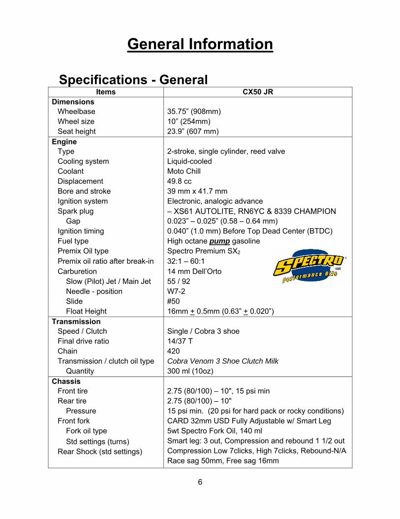
Specifications - General
Items CX50 JR Dimensions
Wheelbase 35.75” (908mm) Wheel size 10” (254mm) Seat height 23.9” (607 mm)
Engine Type 2-stroke, single cylinder, reed valve Cooling system Liquid-cooled Coolant Moto Chill Displacement 49.8 cc Bore and stroke 39 mm x 41.7 mm Ignition system Electronic, analogic advance Spark plug – XS61 AUTOLITE, RN6YC & 8339 CHAMPION Gap 0.023” – 0.025” (0.58 – 0.64 mm) Ignition timing 0.040” (1.0 mm) Before Top Dead Center (BTDC) Fuel type High octane pump gasoline Premix Oil type Spectro Premium SX2
Premix oil ratio after break-in 32:1 – 60:1 Carburetion 14 mm Dell’Orto Slow (Pilot) Jet / Main Jet 55 / 92 Needle - position W7-2 Slide #50 Float Height 16mm + 0.5mm (0.63” + 0.020”)
Transmission Speed / Clutch Single / Cobra 3 shoe Final drive ratio 14/37 T Chain 420 Transmission / clutch oil type Cobra Venom 3 Shoe Clutch Milk Quantity 300 ml (10oz)
Chassis Front tire 2.75 (80/100) – 10", 15 psi min Rear tire 2.75 (80/100) – 10" Pressure 15 psi min. (20 psi for hard pack or rocky conditions) Front fork CARD 32mm USD Fully Adjustable w/ Smart Leg Fork oil type 5wt Spectro Fork Oil, 140 ml
Std settings (turns) Rear Shock (std settings)
Smart leg: 3 out, Compression and rebound 1 1/2 out Compression Low 7clicks, High 7clicks, Rebound-N/A Race sag 50mm, Free sag 16mm
7
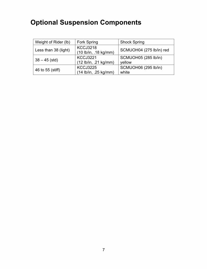
Optional Suspension Components
Weight of Rider (lb) Fork Spring Shock Spring
Less than 38 (light) KCCJ3218 (10 lb/in, .18 kg/mm)
SCMUOH04 (275 lb/in) red
38 – 45 (std) KCCJ3221 (12 lb/in, .21 kg/mm)
SCMUOH05 (285 lb/in) yellow
46 to 55 (stiff) KCCJ3225 (14 lb/in, .25 kg/mm)
SCMUOH06 (295 lb/in) white
8
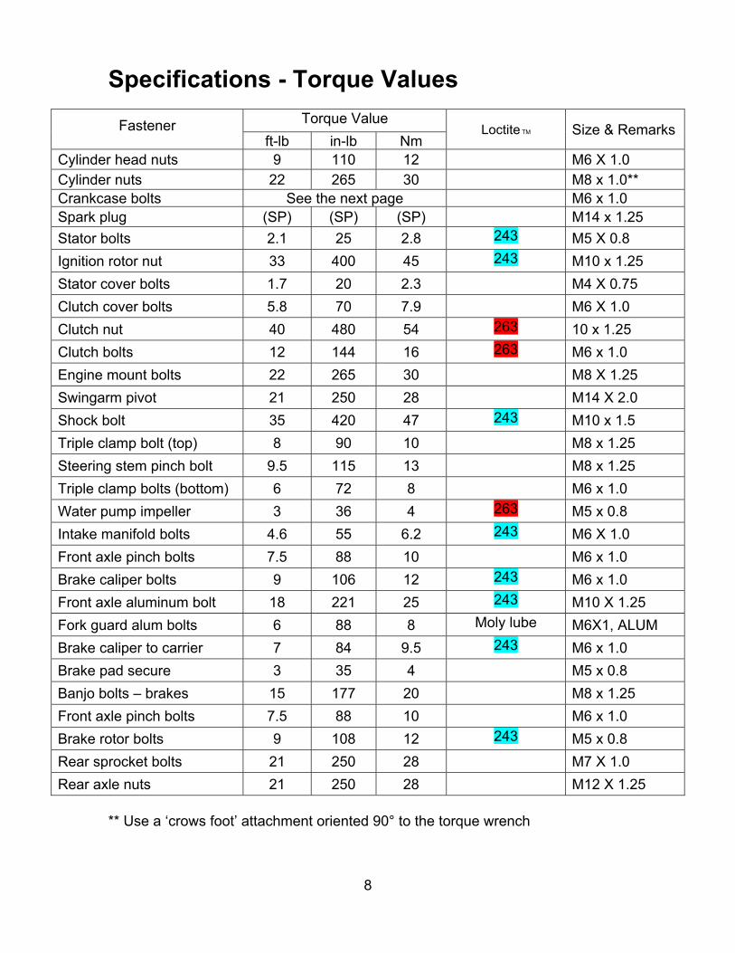
Specifications - Torque Values
Fastener Torque Value Loctite TM Size & Remarks
ft-lb in-lb NmCylinder head nuts 9 110 12 M6 X 1.0 Cylinder nuts 22 265 30 M8 x 1.0** Crankcase bolts See the next page M6 x 1.0Spark plug (SP) (SP) (SP) M14 x 1.25
Stator bolts 2.1 25 2.8 243 M5 X 0.8
Ignition rotor nut 33 400 45 243 M10 x 1.25
Stator cover bolts 1.7 20 2.3 M4 X 0.75
Clutch cover bolts 5.8 70 7.9 M6 X 1.0
Clutch nut 40 480 54 263 10 x 1.25
Clutch bolts 12 144 16 263 M6 x 1.0
Engine mount bolts 22 265 30 M8 X 1.25
Swingarm pivot 21 250 28 M14 X 2.0
Shock bolt 35 420 47 243 M10 x 1.5
Triple clamp bolt (top) 8 90 10 M8 x 1.25
Steering stem pinch bolt 9.5 115 13 M8 x 1.25
Triple clamp bolts (bottom) 6 72 8 M6 x 1.0
Water pump impeller 3 36 4 263 M5 x 0.8
Intake manifold bolts 4.6 55 6.2 243 M6 X 1.0
Front axle pinch bolts 7.5 88 10 M6 x 1.0
Brake caliper bolts 9 106 12 243 M6 x 1.0
Front axle aluminum bolt 18 221 25 243 M10 X 1.25
Fork guard alum bolts 6 88 8 Moly lube M6X1, ALUM
Brake caliper to carrier 7 84 9.5 243 M6 x 1.0
Brake pad secure 3 35 4 M5 x 0.8
Banjo bolts – brakes 15 177 20 M8 x 1.25
Front axle pinch bolts 7.5 88 10 M6 x 1.0
Brake rotor bolts 9 108 12 243 M5 x 0.8
Rear sprocket bolts 21 250 28 M7 X 1.0
Rear axle nuts 21 250 28 M12 X 1.25 ** Use a ‘crows foot’ attachment oriented 90° to the torque wrench

9
(SP) To apply the proper torque to the spark plug when inserting, first screw the spark plug in until the metal gasket ring causes resistance and then turn another ¼ turn.
Engine case torque values
Torque the engine case bolts in the pattern shown above. The upper two bolts have a different toque value compared to the others. Proper torquing procedure would have you lubricating the threads with 30W oil, torquing the bolts all first to an intermediate torque value of 10-12 Nm and then once they are all at that value, proceed back at bolt #1 and toque each bolt further up to the final value.

10
Break-In Procedure Your Cobra CX50 JR is a close-tolerance high performance machine and break-in time is very important for maximum life and performance. The CX50 JR can be ridden hard after the first ½ hour break-in time. Cobra recommends Spectro Premium SX2 premix oil with high octane pump gas mixed at 32:1 (4 oz of oil to a gallon of gas).
CAUTION: Failure to use proper fuel, oil, or fuel/oil mixture may result in premature engine wear or damage to the machine. Adhering to the following break-in schedule will result in long lasting high performance machine. Start bike on stand First 5-minute period, operate the bike on the stand with a combination of idle
and high RPM operation. (avoid prolonged high RPM but spin the rear wheel good at least once or twice per minute)
Allow bike to cool Ride for 15 minutes maximum (avoid prolonged high RPM operation and
avoid abusing the clutch with throttle blipping. Allow bike to cool and inspect bike for loose fasteners. Avoid prolonged operation at Wide Open Throttle for the next half hour. After 1 hour of operation
o Check for loose bolts and nuts. o Clean the carburetor bowl. o Change the transmission / clutch lubricant.
Check CFD torque and adjust as necessary After 8 hours of operation
o Change the fork oil. o Have a Certified Cobra Mechanic or suspension specialist change the shock oil.
Your bike is now ready for the highest level of competition! NOTE: During break-in the bike will likely lose some engine coolant through the radiator overflow hose. Losing up to 4 oz (120 ml) is normal. Proper coolant level will cover the top of the radiator cores. Removing the radiator cap and looking inside is the only way to check the coolant level.
Never remove the radiator cap of a machine that has a warm engine. Burning and scalding could occur.

11
Starting Procedure Before starting the machine inspect the following: Tire pressure Chain tension Coolant level Proper wear on chain rollers and sliders Handlebar tightness Throttle assembly movement/cable adjustment Air Filter Check for loose nuts and bolts Turn the fuel on by rotating the fuel petcock knob to the vertically downward
position (reserve position is horizontally forward) NOTE: For best results from your Cobra Motorcycle use only the recommended fuel. Testing has shown that most ‘race’ fuels actually degrade performance.
Always wear a helmet and other protective riding gear. When your pre-ride inspection is complete the bike may be started. For a cold engine follow this procedure. 1. Place the motorcycle on a stand of sufficient strength that positions the
motorcycle in a level upright position with the rear wheel off the ground. 2. Pull up the choke knob and turn it to lock it. 3. Kick start the engine. 4. Rev the engine in short spurts, turning the throttle no more than 1/4 open
until the engine will run without the choke. 5. Verify a functional engine shut-off switch by shutting off the engine. 6. Restart the engine and proceed with riding when the engine is sufficiently
warm (i.e. the side of the cylinder is warm to touch). CAUTION: Never rev an engine full throttle until the engine is at operating temperature.
This is a high performance race motorcycle. Too much application of throttle will likely land your little racer on his or her arse. Fenders can be replaced but bruised egos and other body parts take longer. CAUTION: Cobra recommends that you tell your child to take it easy the first couple of minutes in practice until the engine comes up to full operating temperature.

12
CAUTION: Make sure your riders’ foot is not resting on the foot brake while they are riding.
Maintenance A properly maintained machine is safer, faster, and more fun to ride. It is important that you adhere to this maintenance schedule so as to promote the longevity of your Cobra Motorcycle
Tips 1. Recommended lubricants:
a. Cobra Clutch Milk is by far the best auto clutch lubricant. It is a full synthetic lubricant that has been specifically formulated for Cobra’s auto clutch and has;
Exceptional film strength over petroleum based oils or synthetic blends.
Extreme temperature tolerance. NO frictional modifiers. Dispersant package to keep clutch fibers in suspension so
they can be flushed out when the oil is changed. Extremely low viscosity for minimal drag and ‘windage’.
b. Spectro Premium SX2 oil is the recommended premix oil because: Its Ester base leaves a film on all parts at all times. No metal
to metal startups or corrosion potential. Exception film strength over petroleum based oils or other
synthetic blends. Easily atomizes and burns completely. Does not fall out of suspension from premix in cold weather. Produces virtually no coking deposits, leaving pistons, rings
and heads extremely clean with minimal pipe ‘spooge’. 2. Filling your transmission with more than 8.0 oz (235 cc) of lubricant will help
to transfer heat from the clutch. Filling with more than 12 oz (355 cc) will degrade performance.
3. The cylinder base gasket has been ‘fitted’ for your engine. The code number stamped into the engine cases will guide you to what thickness base gasket is required during a common top end service. See the service section of this manual to correspond a code number with a base gasket part number.
4. Evaluate the bikes jetting only after it has been warmed up to race temperatures.
5. New chains will stretch on first use. Never install a new chain prior to a race. Always ‘break’ them in during practice.
6. Your Cobra Motorcycle has a 10-digit VIN (Vehicle Identification Number). The first three digits indicate the model while the sixth and seventh indicates the model year.

13
a. Example, CJRxx17xxx is a 2017 CX50 JR. 7. Because of the amount of heat generated by the clutch and engine during
extended periods of riding, it is advisable to remove the ignition cover afterward to allow the ignition to cool off. The heat transfers through the cases and can damage the stator as it cools off because of lack of airflow around the stator.
8. If you ever need to weld anything on the bike, disconnect the spark plug cap, unplug the ignition, disconnect the kill switch, scrape the paint bare near the area to be welded and put the ground clamp as close to the area to be welded as possible.
Be sure the fuel tank and carburetor have been removed and safely located away from the welding process.
9. The frame is 4130 Chrome Moly and it is important to weld it with the proper rod and heat settings set as light as possible. Cobra recommends replacing the frame with a new one if the old one becomes damaged. Use ER70S6 filler if welding on the frame.
10. If your kick-starter lever does not return properly, first try loosening the six kick/clutch cover screws ½ turn. Hold the kick lever ½ way down while retightening the six screws starting for the center and working out
11. Inspect CFD slip torque after the 2nd ride and then again after the 6th ride. After this follow the recommended schedule below.
12. Check proper clutch engagement before and after each ride. If the clutch is engaging properly DO NOT feel the need to take the clutch apart to; measure the spring stack, clean the stack, replace the springs, etc... Cobra has worked very hard to make a clutch that is low maintenance and so only take it apart if it NEEDS to be maintained.
Schedule Prior to each ride
o Check that the air filter is cleaned and oiled. o Insure the smooth operation of the throttle cable (throttle soundly ‘clacks’
shut). o Check for frayed strands of the throttle cable inside the throttle housing. o Check for adequate tire pressure. o Check all nuts and bolts for proper torque. o Spray all moving parts with WD40 or other light oil. o Check drive chain for
Proper tension. Adequate lubrication.
o Insure that the ignition stator and rotor are clean and dry. o Check the frame for cracks in the metal or cracks in the paint that might
Indicate that the metal has been stressed beyond its safe limits. o Check the rims for signs of stress, like cracks around the rim, spokes and hub.
14
o Equalize the pressure in the forks with atmosphere. Every 2 hours of operation
o Replace the transmission oil. o Check the CFD torque
Every 10 hours of operation o Replace the fork oil. o Have the shock oil replaced by a Certified Cobra Mechanic.
Replacing Transmission / Clutch Lubricant Tools needed: 5mm allen wrench Minimum of 300 cc (10 oz) Cobra Venom 3 Shoe Clutch Milk (Part
#MCMUGF32). Procedure: 1. Begin this procedure with a bike that has been ridden more than 5 minutes
but less than 10 minutes. It is desired to have the engine warm enough so that the oil is ‘runny’ but not so hot that there is risk of being burned by the engine or the oil.
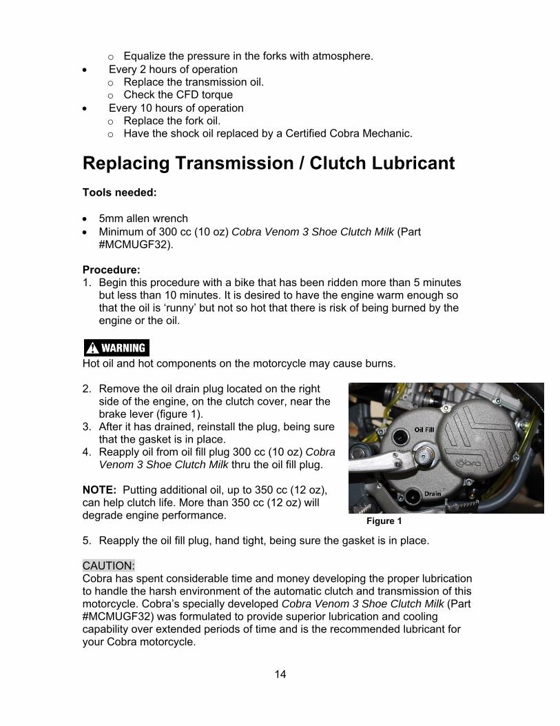
Hot oil and hot components on the motorcycle may cause burns. 2. Remove the oil drain plug located on the right
side of the engine, on the clutch cover, near the brake lever (figure 1).
3. After it has drained, reinstall the plug, being sure that the gasket is in place.
4. Reapply oil from oil fill plug 300 cc (10 oz) Cobra Venom 3 Shoe Clutch Milk thru the oil fill plug.
NOTE: Putting additional oil, up to 350 cc (12 oz), can help clutch life. More than 350 cc (12 oz) will degrade engine performance. 5. Reapply the oil fill plug, hand tight, being sure the gasket is in place. CAUTION: Cobra has spent considerable time and money developing the proper lubrication to handle the harsh environment of the automatic clutch and transmission of this motorcycle. Cobra’s specially developed Cobra Venom 3 Shoe Clutch Milk (Part #MCMUGF32) was formulated to provide superior lubrication and cooling capability over extended periods of time and is the recommended lubricant for your Cobra motorcycle.
Figure 1
15
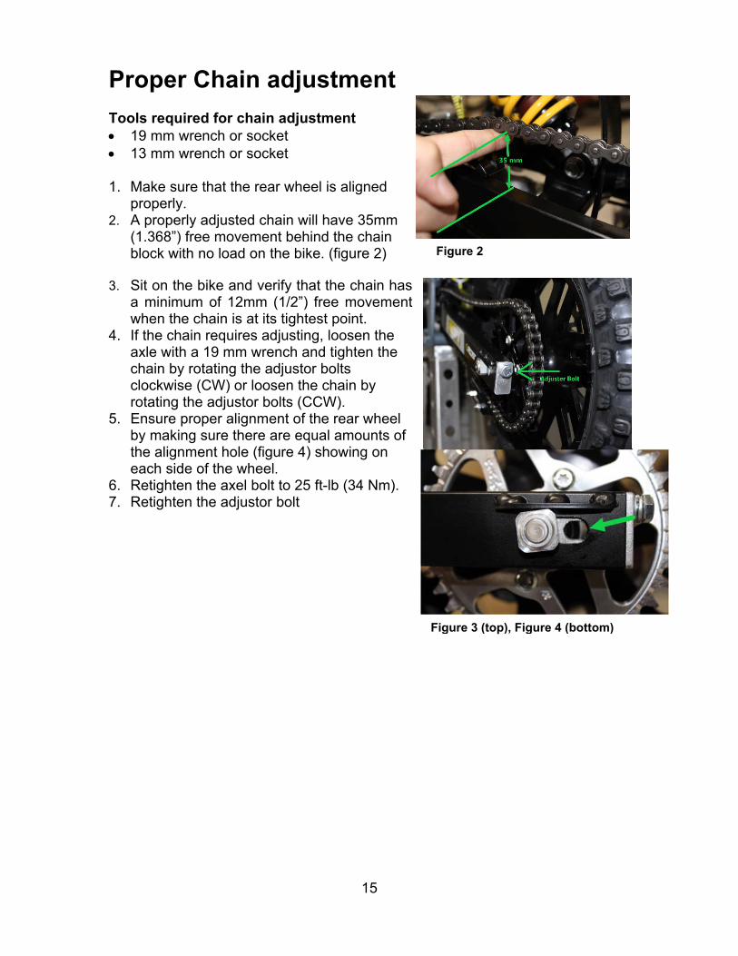
Proper Chain adjustment Tools required for chain adjustment 19 mm wrench or socket 13 mm wrench or socket 1. Make sure that the rear wheel is aligned
properly. 2. A properly adjusted chain will have 35mm
(1.368”) free movement behind the chain block with no load on the bike. (figure 2)
3. Sit on the bike and verify that the chain has a minimum of 12mm (1/2”) free movement when the chain is at its tightest point.
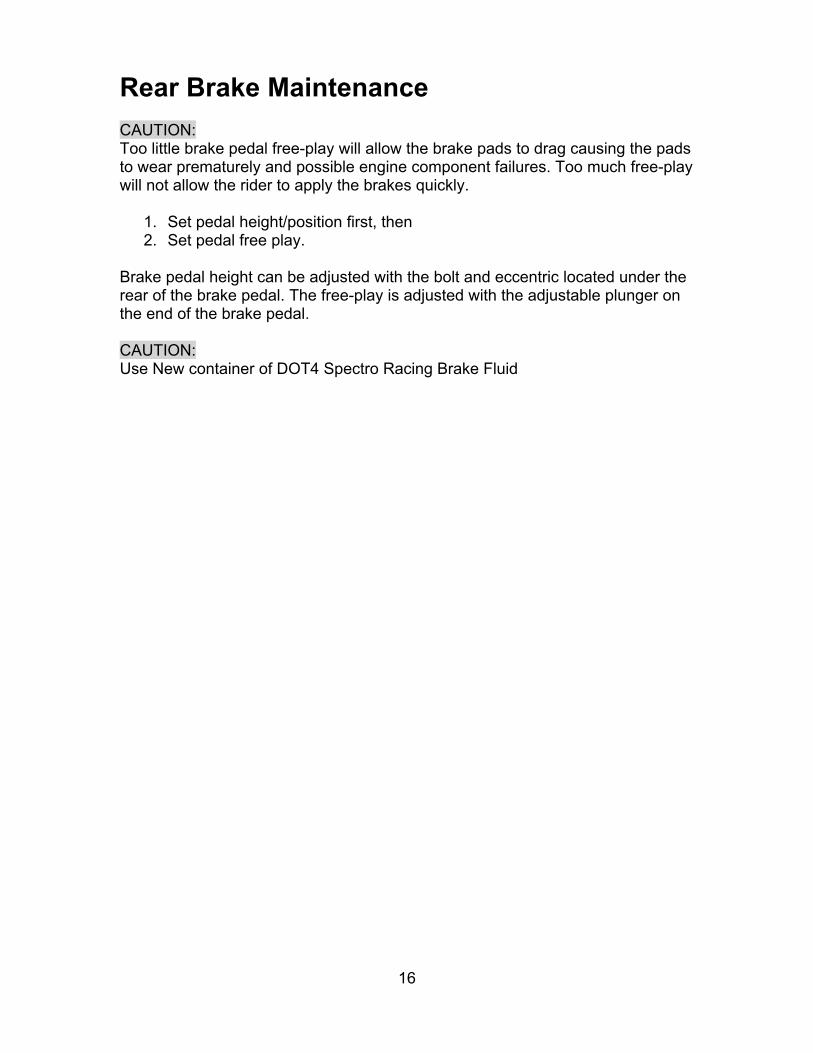
4. If the chain requires adjusting, loosen the axle with a 19 mm wrench and tighten the chain by rotating the adjustor bolts clockwise (CW) or loosen the chain by rotating the adjustor bolts (CCW).
5. Ensure proper alignment of the rear wheel by making sure there are equal amounts of the alignment hole (figure 4) showing on each side of the wheel.
6. Retighten the axel bolt to 25 ft-lb (34 Nm). 7. Retighten the adjustor bolt
Figure 2
Figure 3 (top), Figure 4 (bottom)
16
Rear Brake Maintenance CAUTION: Too little brake pedal free-play will allow the brake pads to drag causing the pads to wear prematurely and possible engine component failures. Too much free-play will not allow the rider to apply the brakes quickly.
1. Set pedal height/position first, then 2. Set pedal free play.
Brake pedal height can be adjusted with the bolt and eccentric located under the rear of the brake pedal. The free-play is adjusted with the adjustable plunger on the end of the brake pedal. CAUTION: Use New container of DOT4 Spectro Racing Brake Fluid

17
Setting rear brake pedal position (see figure 2b): 1. Loosen the Cap Screw in the Eccentric (5mm Allen wrench). 2. Rotate the eccentric so that the lever is comfortably reachable in both:
a. Standing riding position, and b. Sitting riding position.
3. Tighten Cap Screw (5 mm Allen wrench). CAUTION: Adequate pedal free play is required so that the brake pads do not drag on the rotor.
Make sure that the free play locking clip is installed such that one must push forward, toward the front of the bike, to remove. Otherwise the clip is apt to come undone while riding. To adjust freeplay (see figure 2b):
1. Loosen the lock nut (10mm). 2. Undo the free play locking clip from around the brake adjustor (plunger),
with your hand by pushing it forward. 3. Slide the pin of the locking free play locking clip from the brake lever 4. Adjust as needed by rotating the clevis on the end of the adjustor
(plunger). NOTE: Turning the clevis Clockwise will lengthen the adjustor (plunger), removing free play from the system, and turning the clevis Counter-Clockwise will shorten the adjustor (plunger) adding free play to the system.
Air Filter Cleaning Tools recommended for air filter maintenance: #2 Phillips head screwdriver 4 mm Allen wrench Foam filter oil Procedure 1. Removed the seat with a 4 mm Allen wrench. 2. Remove the filter/air inlet boot from the back of the carburetor with a Phillips
screwdriver 3. Pull the filter / boot assembly out the top of the air box. 4. Clean the filter in a nonflammable solvent to remove the filter oil.
Do not clean the air filter with gasoline or other highly volatile petroleum product. Diesel fuel or kerosene would be preferred but caution should still be taken. Hot soapy water works well.
Figure 2b
18
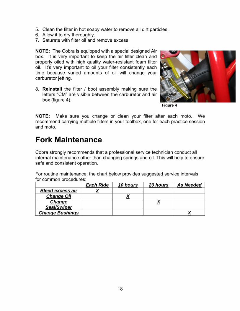
5. Clean the filter in hot soapy water to remove all dirt particles. 6. Allow it to dry thoroughly. 7. Saturate with filter oil and remove excess. NOTE: The Cobra is equipped with a special designed Air box. It is very important to keep the air filter clean and properly oiled with high quality water-resistant foam filter oil. It’s very important to oil your filter consistently each time because varied amounts of oil will change your carburetor jetting. 8. Reinstall the filter / boot assembly making sure the
letters “CM” are visible between the carburetor and air box (figure 4).
NOTE: Make sure you change or clean your filter after each moto. We recommend carrying multiple filters in your toolbox, one for each practice session and moto.
Fork Maintenance Cobra strongly recommends that a professional service technician conduct all internal maintenance other than changing springs and oil. This will help to ensure safe and consistent operation. For routine maintenance, the chart below provides suggested service intervals for common procedures:
Each Ride 10 hours 20 hours As NeededBleed excess air X
Change Oil X Change
Seal/Swiper X
Change Bushings X
Figure 4

19
Fork Air Bleeding Tools required 3mm hex key (Allen wrench)
During normal operation, both fork legs will build up air pressure. This pressure acts as an additional spring so it must be bled on a regular basis to maintain consistent suspension operation. Before each ride, loosen the socket head cap screw located at the front of each fork cap far enough so that any excess pressure in the leg is relieved. After excess air is bled off, retighten the screw to 5 in-lb. Be careful not to lose or damage the sealing ring that is located under the head of each bleed screw.
Fork Oil Replacement Tools required 32mm Fork Cap Tool (MCMUTL32) 19mm wrench or socket 4 & 5 mm hex key (Allen wrench) 9/16 wrench Mallet 5 wt. Spectro fork oil Disassembly procedure 1. Remove the front wheel (19 mm wrench). 2. Remove the brake caliper from the fork leg (4 mm hex key). 3. Loosen the fork caps (32mm fork cap tool). 4. Remove the fork legs from the triple clamps (5 mm hex key). 5. One leg at a time
a. Remove the fork cap from the fork tube. b. Pull the fork spring down to gain access to the fork cap jam nut and
secure it with a 9/16 wrench. c. Holding in one hand the 9/16 wrench use the fork cap wrench to
unscrew the fork cap from the damper rod. d. Remove the fork spring pad, and fork spring. e. Inside the damper rod, the rebound adjustment screw pin is resting
and will fall out of the damper rod when the fork is inverted. Try to catch it before it falls into your oil bucket.
f. Invert the fork and allow the oil to drain completely. Working the damper rod up and down will speed up the draining process.
Assembly procedure 1. Fill the fork with 140ml of fork oil. 2. Work the damper rod up and down to allow the fork cartridge to fill with oil. 3. Install the rebound adjustment screw pin into the damper rod. 4. Install the fork spring and spring pad.
20
5. Extend the damper rod completely and Compress the fork spring enough to begin threading the fork cap back onto the damper rod.
6. Make sure that the fork cap threads onto the damper rod completely before it makes contact with the jamnut.
7. Tighten the jamnut. 8. Tighten the fork cap to the fork leg outer 9. Pump the fork leg several times to verify that it operates smoothly. 10. Install each leg back into the triple clamp. Torque each pinch bolt to 8N-m (6
ft-lb) making sure both legs are set to the same height in the clamps. 11. Reinstall the brake caliper. 12. Reinstall the front wheel (25 ft-lb, 34 Nm).
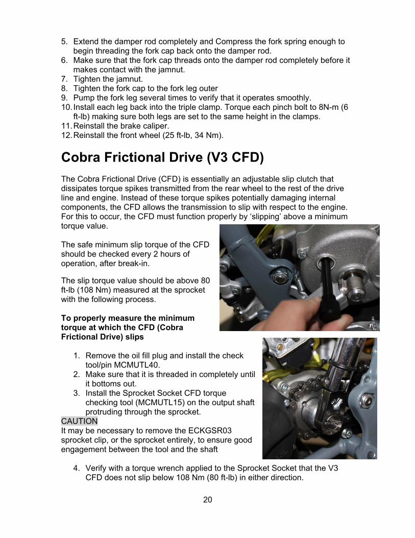
Cobra Frictional Drive (V3 CFD) The Cobra Frictional Drive (CFD) is essentially an adjustable slip clutch that dissipates torque spikes transmitted from the rear wheel to the rest of the drive line and engine. Instead of these torque spikes potentially damaging internal components, the CFD allows the transmission to slip with respect to the engine. For this to occur, the CFD must function properly by ‘slipping’ above a minimum torque value. The safe minimum slip torque of the CFD should be checked every 2 hours of operation, after break-in. The slip torque value should be above 80 ft-lb (108 Nm) measured at the sprocket with the following process. To properly measure the minimum torque at which the CFD (Cobra Frictional Drive) slips
1. Remove the oil fill plug and install the check tool/pin MCMUTL40.
2. Make sure that it is threaded in completely until it bottoms out.
3. Install the Sprocket Socket CFD torque checking tool (MCMUTL15) on the output shaft protruding through the sprocket.
CAUTION It may be necessary to remove the ECKGSR03 sprocket clip, or the sprocket entirely, to ensure good engagement between the tool and the shaft
4. Verify with a torque wrench applied to the Sprocket Socket that the V3 CFD does not slip below 108 Nm (80 ft-lb) in either direction.
21
5. If there is slippage below 108 Nm (80 ft-lb) remove the cotter pin and tighten the castle nut on the CFD one more position (it is a left hand thread nut so you must turn it counter clockwise)
NOTE: This V3 CFD torque checking method is possible do to with the chain on. Just put the bike on a stand so that the rear wheel can turn freely. NOTE: The CFD hubs can be removed with the universal puller (MCMUTL70). If it slips below the value, the CFD must be readjusted as per described in the service section of this manual. NOTE: If the bike makes a whir, whir, whir, sound coming from the clutch side engine cover it is very probable that the CFD has slipped enough that the brass bushing has worn sufficiently to let the gear operate off center. Time to install a CFD refresh kit (EKMU0033).
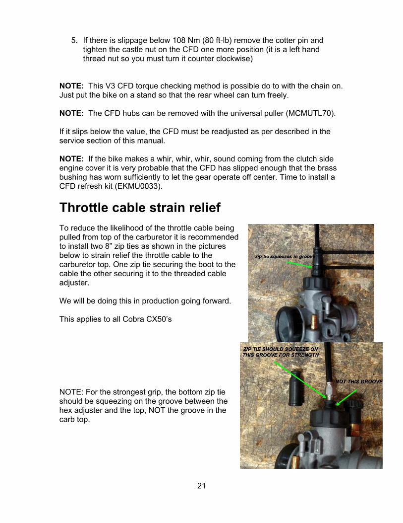
Throttle cable strain relief To reduce the likelihood of the throttle cable being pulled from top of the carburetor it is recommended to install two 8” zip ties as shown in the pictures below to strain relief the throttle cable to the carburetor top. One zip tie securing the boot to the cable the other securing it to the threaded cable adjuster. We will be doing this in production going forward. This applies to all Cobra CX50’s
NOTE: For the strongest grip, the bottom zip tie should be squeezing on the groove between the hex adjuster and the top, NOT the groove in the carb top.
22
Parts
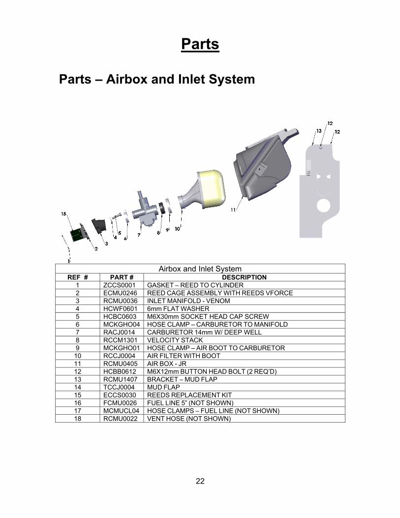
Parts – Airbox and Inlet System
Airbox and Inlet System
REF # PART # DESCRIPTION1 ZCCS0001 GASKET – REED TO CYLINDER2 ECMU0246 REED CAGE ASSEMBLY WITH REEDS VFORCE 3 RCMU0036 INLET MANIFOLD - VENOM4 HCWF0601 6mm FLAT WASHER5 HCBC0603 M6X30mm SOCKET HEAD CAP SCREW6 MCKGHO04 HOSE CLAMP – CARBURETOR TO MANIFOLD 7 RACJ0014 CARBURETOR 14mm W/ DEEP WELL8 RCCM1301 VELOCITY STACK9 MCKGHO01 HOSE CLAMP – AIR BOOT TO CARBURETOR 10 RCCJ0004 AIR FILTER WITH BOOT11 RCMU0405 AIR BOX - JR12 HCBB0612 M6X12mm BUTTON HEAD BOLT (2 REQ’D)13 RCMU1407 BRACKET – MUD FLAP14 TCCJ0004 MUD FLAP
15 ECCS0030 REEDS REPLACEMENT KIT16 FCMU0026 FUEL LINE 5” (NOT SHOWN)17 MCMUCL04 HOSE CLAMPS – FUEL LINE (NOT SHOWN)18 RCMU0022 VENT HOSE (NOT SHOWN)

23
Parts – Bars and Controls
Bars and ControlsREF # PART # DESCRIPTION
1 FAMU0017 HANDLEBAS – PRO TAPER MICROBARS – COBRA JR/P32 TCMU0021 GRIPS (SET OF TWO) – MICROGRIPS – RED / GRAY FWE3 FAMU0016 THROTTLE ASSEMBLY – PRO TAPER COBRA
3A FAMU0015 TUBE ASSEMBLY – THROTTLE – 2 PIECE PRO TAPER MICRO3B HCBC0525 M5 X 25 SHCS – THROTTLE ASSEMBLY3C FCMU0041 STOP RING – MICRO BAR THROTTLE4 FCPW0004 CABLE COVER5 FCMU0021 THROTTLE COVER6 FCMU0019 THROTTLE CABLE
6A HCNJ0801 NUT – 8MM JAM7 SEE FRONT BRAKE8 FCMU0033 KILL SWITCH ASSEMBLY9 HCBC0806 M8X30mm SOCKET HEAD CAP SCREW (4 REQ’D) 10 TCMU0060 BAR CLAMP
ACCESSORY MCMUAM11 GRIP DONUT – PAIR – PRO TAPER MICRO BAR
ACCESSORY FKMU0007 HANDLEBAR KIT– PRO TAPER MICRO WITH COBRA THROTTLE AND GRIPS
24
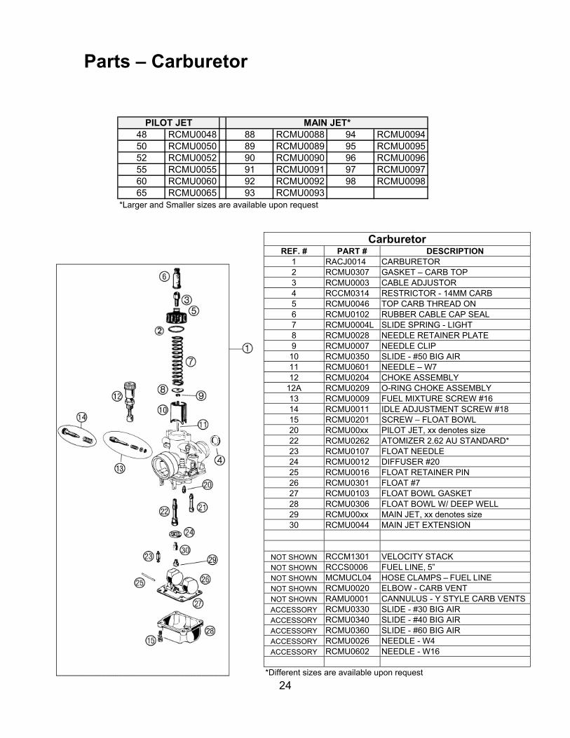
Parts – Carburetor
48 RCMU0048 88 RCMU0088 94 RCMU009450 RCMU0050 89 RCMU0089 95 RCMU009552 RCMU0052 90 RCMU0090 96 RCMU009655 RCMU0055 91 RCMU0091 97 RCMU009760 RCMU0060 92 RCMU0092 98 RCMU009865 RCMU0065 93 RCMU0093
PILOT JET MAIN JET*
*Larger and Smaller sizes are available upon request
Carburetor REF. # PART # DESCRIPTION
1 RACJ0014 CARBURETOR 2 RCMU0307 GASKET – CARB TOP 3 RCMU0003 CABLE ADJUSTOR 4 RCCM0314 RESTRICTOR - 14MM CARB 5 RCMU0046 TOP CARB THREAD ON 6 RCMU0102 RUBBER CABLE CAP SEAL7 RCMU0004L SLIDE SPRING - LIGHT 8 RCMU0028 NEEDLE RETAINER PLATE 9 RCMU0007 NEEDLE CLIP
10 RCMU0350 SLIDE - #50 BIG AIR 11 RCMU0601 NEEDLE – W7 12 RCMU0204 CHOKE ASSEMBLY
12A RCMU0209 O-RING CHOKE ASSEMBLY 13 RCMU0009 FUEL MIXTURE SCREW #16 14 RCMU0011 IDLE ADJUSTMENT SCREW #1815 RCMU0201 SCREW – FLOAT BOWL 20 RCMU00xx PILOT JET, xx denotes size 22 RCMU0262 ATOMIZER 2.62 AU STANDARD*23 RCMU0107 FLOAT NEEDLE 24 RCMU0012 DIFFUSER #20 25 RCMU0016 FLOAT RETAINER PIN26 RCMU0301 FLOAT #7 27 RCMU0103 FLOAT BOWL GASKET 28 RCMU0306 FLOAT BOWL W/ DEEP WELL29 RCMU00xx MAIN JET, xx denotes size 30 RCMU0044 MAIN JET EXTENSION
NOT SHOWN RCCM1301 VELOCITY STACK NOT SHOWN RCCS0006 FUEL LINE, 5” NOT SHOWN MCMUCL04 HOSE CLAMPS – FUEL LINE NOT SHOWN RCMU0020 ELBOW - CARB VENT NOT SHOWN RAMU0001 CANNULUS - Y STYLE CARB VENTSACCESSORY RCMU0330 SLIDE - #30 BIG AIR ACCESSORY RCMU0340 SLIDE - #40 BIG AIR ACCESSORY RCMU0360 SLIDE - #60 BIG AIRACCESSORY RCMU0026 NEEDLE - W4 ACCESSORY RCMU0602 NEEDLE - W16
*Different sizes are available upon request
25
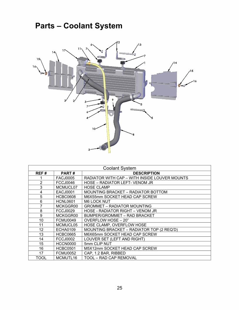
Parts – Coolant System
Coolant System
REF # PART # DESCRIPTION1 FACJ0005 RADIATOR WITH CAP – WITH INSIDE LOUVER MOUNTS 2 FCCJ0046 HOSE – RADIATOR LEFT- VENOM JR3 MCMUCL07 HOSE CLAMP4 EACJ0001 MOUNTING BRACKET – RADIATOR BOTTOM5 HCBC0608 M6X55mm SOCKET HEAD CAP SCREW6 HCNL0601 M6 LOCK NUT7 MCKGGR00 GROMMET – RADIATOR MOUNTING8 FCCJ0029 HOSE - RADIATOR RIGHT – VENOM JR9 MCKGGR00 BUMPER/GROMMET – RAD BRACKET10 FCMU0049 OVERFLOW HOSE – 20”11 MCMUCL05 HOSE CLAMP, OVERFLOW HOSE12 ECHA0109 MOUNTING BRACKET – RADIATOR TOP (2 REQ’D) 13 HCBC0665 M6X65mm SOCKET HEAD CAP SCREW14 FCCJ0002 LOUVER SET (LEFT AND RIGHT)15 HCCN0000 5mm CLIP NUT16 HCBC0501 M5X12mm SOCKET HEAD CAP SCREW17 FCMU0052 CAP, 1.2 BAR, RIBBED
TOOL MCMUTL16 TOOL – RAD CAP REMOVAL
26
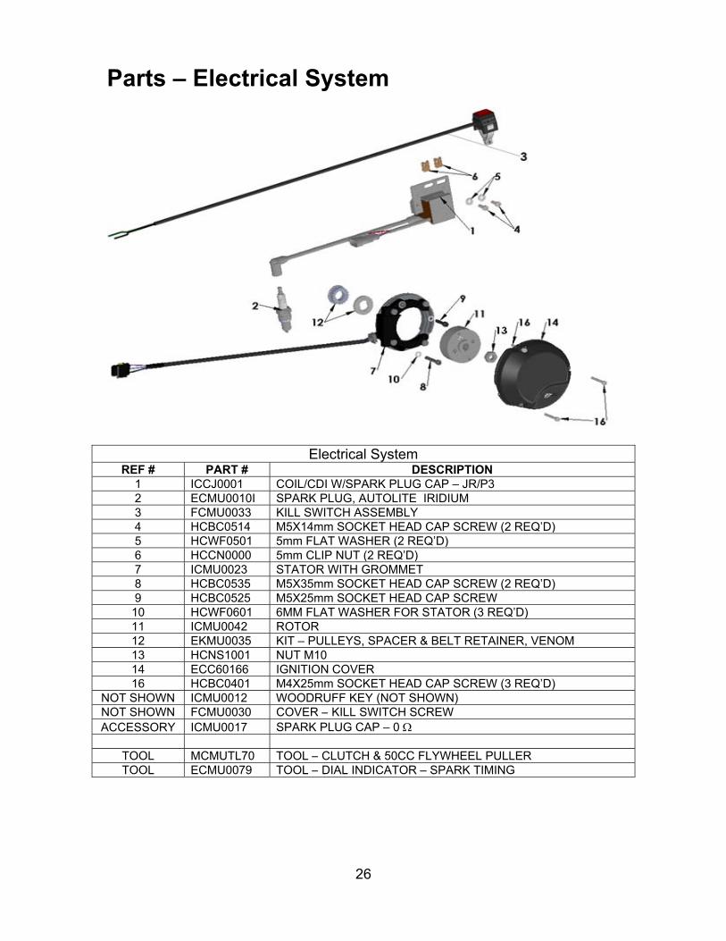
Parts – Electrical System
Electrical SystemREF # PART # DESCRIPTION
1 ICCJ0001 COIL/CDI W/SPARK PLUG CAP – JR/P32 ECMU0010I SPARK PLUG, AUTOLITE IRIDIUM3 FCMU0033 KILL SWITCH ASSEMBLY4 HCBC0514 M5X14mm SOCKET HEAD CAP SCREW (2 REQ’D) 5 HCWF0501 5mm FLAT WASHER (2 REQ’D)6 HCCN0000 5mm CLIP NUT (2 REQ’D)7 ICMU0023 STATOR WITH GROMMET8 HCBC0535 M5X35mm SOCKET HEAD CAP SCREW (2 REQ’D) 9 HCBC0525 M5X25mm SOCKET HEAD CAP SCREW10 HCWF0601 6MM FLAT WASHER FOR STATOR (3 REQ’D) 11 ICMU0042 ROTOR 12 EKMU0035 KIT – PULLEYS, SPACER & BELT RETAINER, VENOM 13 HCNS1001 NUT M1014 ECC60166 IGNITION COVER16 HCBC0401 M4X25mm SOCKET HEAD CAP SCREW (3 REQ’D)
NOT SHOWN ICMU0012 WOODRUFF KEY (NOT SHOWN)NOT SHOWN FCMU0030 COVER – KILL SWITCH SCREWACCESSORY ICMU0017 SPARK PLUG CAP – 0
TOOL MCMUTL70 TOOL – CLUTCH & 50CC FLYWHEEL PULLER TOOL ECMU0079 TOOL – DIAL INDICATOR – SPARK TIMING

27
This Page Intentionally Left Blank
28
Parts – Engine – Bottom End and Transmission
29
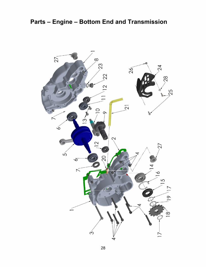
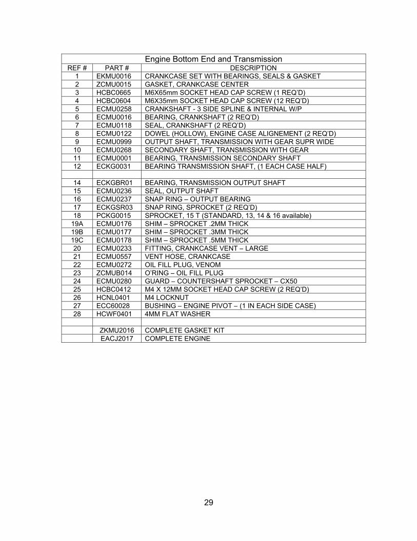
Engine Bottom End and TransmissionREF # PART # DESCRIPTION
1 EKMU0016 CRANKCASE SET WITH BEARINGS, SEALS & GASKET 2 ZCMU0015 GASKET, CRANKCASE CENTER3 HCBC0665 M6X65mm SOCKET HEAD CAP SCREW (1 REQ’D) 4 HCBC0604 M6X35mm SOCKET HEAD CAP SCREW (12 REQ’D) 5 ECMU0258 CRANKSHAFT - 3 SIDE SPLINE & INTERNAL W/P 6 ECMU0016 BEARING, CRANKSHAFT (2 REQ’D)7 ECMU0118 SEAL, CRANKSHAFT (2 REQ’D)8 ECMU0122 DOWEL (HOLLOW), ENGINE CASE ALIGNEMENT (2 REQ’D)9 ECMU0999 OUTPUT SHAFT, TRANSMISSION WITH GEAR SUPR WIDE 10 ECMU0268 SECONDARY SHAFT, TRANSMISSION WITH GEAR 11 ECMU0001 BEARING, TRANSMISSION SECONDARY SHAFT 12 ECKG0031 BEARING TRANSMISSION SHAFT, (1 EACH CASE HALF)
14 ECKGBR01 BEARING, TRANSMISSION OUTPUT SHAFT15 ECMU0236 SEAL, OUTPUT SHAFT 16 ECMU0237 SNAP RING – OUTPUT BEARING17 ECKGSR03 SNAP RING, SPROCKET (2 REQ’D)18 PCKG0015 SPROCKET, 15 T (STANDARD, 13, 14 & 16 available)
19A ECMU0176 SHIM – SPROCKET .2MM THICK19B ECMU0177 SHIM – SPROCKET .3MM THICK19C ECMU0178 SHIM – SPROCKET .5MM THICK20 ECMU0233 FITTING, CRANKCASE VENT – LARGE21 ECMU0557 VENT HOSE, CRANKCASE22 ECMU0272 OIL FILL PLUG, VENOM23 ZCMUB014 O’RING – OIL FILL PLUG24 ECMU0280 GUARD – COUNTERSHAFT SPROCKET – CX50 25 HCBC0412 M4 X 12MM SOCKET HEAD CAP SCREW (2 REQ’D) 26 HCNL0401 M4 LOCKNUT27 ECC60028 BUSHING – ENGINE PIVOT – (1 IN EACH SIDE CASE) 28 HCWF0401 4MM FLAT WASHER ZKMU2016 COMPLETE GASKET KIT EACJ2017 COMPLETE ENGINE

30
Parts – Engine Clutch and Kick Lever

31
Engine – Clutch and Kick StarterREF # PART # DESCRIPTION
1 CACJ0100 CLUTCH COMPLETE ASSY - 5GX2 CACJ0010 3 SHOES & WASHER STACKS W BOLTS - 5GX3 CCMU0005 CLUTCH ARBOR – 3 SIDED SPLINE4 CACJ0001 WASHER STACKS - SET OF 3 - CLUTCH - 5GX5 HCBT0001 BOLT - TORX - 5GX CLUTCH - M6 X 296 CCMU0008 SLEEVE - CLUTCH STACK 5GX7 ECMU0018 CLUTCH NUT, SPECIAL8 ECDC0030 BELLEVILLE LOCK WASHER9 CCMU0007 CLUTCH BACKING SPACER10 ECMU0120 CLUTCH BASKET WITH NEEDLE BEARING11 ECMU0119 CLUTCH BEARING12 ECMU0040 CLUTCH TO HUB SPACER(S) (0.030”, 0.76mm)13 ECMU0132 FITTING - COOLANT14 ECMU0307 NUT V3 CFD15 HCCP0002 COTTER PIN 3/32 X 1 ½”16 ECMU0308 BELLEVILLE SPRING V3 CFD17 ECMU0306 SLIP HUB V3 CFD (2) REQ’D18 ECMU0249 FRICTION MATERIAL V3 CFDTHICK (2 REQ’D)19 ECMU0301 GEAR V3 CFD20 ECMU0305 BUSHING V3 CFD 7mm21 ECMU0272 OIL FILL PLUG, VENOM22 ZCMUB014 O’RING – OIL FILL PLUG23 HCFH0616 M6X16mm FLAT HEAD BOLT24 ECMU0250 WASHER – KICK LEVER MOUNTING25 EAMU0011 KICK LEVER26 ECDC0078 SEAL - KICKSHAFT28 HCBC0608 M6X55mm SHCS (2 REQ’D)29 ECMU0263 CLUTCH COVER ASSEMBLY WITH SEAL AND PIN 30 ZCMU0017 GASKET - CLUTCH COVER31 ECMU0273 SPRING, KICKSTART32 ECMUSP01 KICK START DOG SPRING (PAPER CLIP / ‘J’ SPRING) 33 ECMU0207 KICKSTART GEAR SMALL34 ECMU0278 BRACKET – KICK SHAFT RETAINING35 HCBC0508 M5 X 8mm SHCS (2 REQ’D)36 ECMU0269 KICKSTART GEAR & SHAFT
KIT HKCP0001 10 PACK OF COTTER PINS (HCCP0002)KIT EKMU0002 KICKSTART PIVOT KIT SPRING-BALL-SCREWKIT HKAM0022 CLUTCH SHIM HARDEWARE KITKIT EKMU0033 CFD RFRESH KIT W’ FRICTIONS, SPRING, BUSHING AND COTTER PINS
TOOL MCMUTL40 TOOL - CFD – CHECK STOP PIN - VENOMTOOL MCMUTL18 TOOL – SPROCKET SOCKET – HIGH TORQUETOOL ECMU0078 TOOL – SOCKET - CLUTCH NUT – CX50TOOL MCMUTL03 TOOL – PISTON STOPTOOL MCMUTL70 TOOL – PULLER – CLUTCH AND FLYWHEEL – CX50
32
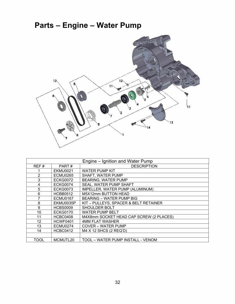
Parts – Engine – Water Pump
Engine – Ignition and Water PumpREF # PART # DESCRIPTION
1 EKMU0021 WATER PUMP KIT2 ECMU0265 SHAFT, WATER PUMP3 ECKG0072 BEARING, WATER PUMP4 ECKG0074 SEAL, WATER PUMP SHAFT5 ECKG0073 IMPELLER, WATER PUMP (ALUMINUM)6 HCBB0512 M5X12mm BUTTON HEAD7 ECMU0167 BEARING – WATER PUMP BIG8 EKMU0035P KIT – PULLEYS, SPACER & BELT RETAINER9 HCBS0009 SHOULDER BOLT 10 ECKG0170 WATER PUMP BELT11 HCBC0408 M4X8mm SOCKET HEAD CAP SCREW (2 PLACES) 12 HCWF0401 4MM FLAT WASHER13 ECMU0274 COVER – WATER PUMP14 HCBC0412 M4 X 12 SHCS (2 REQ’D)
TOOL MCMUTL20 TOOL – WATER PUMP INSTALL - VENOM

33
Parts – Engine – Top End
Engine – Top EndREF # PART # DESCRIPTION
1 EKMU0361 CYLINDER KIT (INCLUDES STUDS, PISTON, RINGS, PIN & CLIPS)2 ZCMU0102 BASE GASKET (0.20mm) THICK2 ZCMU0103 BASE GASKET (0.30mm) THICK2 ZCMU0104 BASE GASKET (0.40mm) THICK2 ZCMU0105 BASE GASKET (0.50mm) THICK2 ZCMU0106 BASE GASKET (0.60mm) THICK2 ZCMU0107 BASE GASKET (0.70mm) THICK2 ZCMU0108 BASE GASKET (0.80mm) THICK3 ECMU0276A PISTON KIT – ‘A’ SIZE (B, C, and D sizes available) 4 ECMU0077 BEARING, WRIST PIN 5 ECMU0155 PISTON RINGS (2 PER SET)6 ECMUSR00 SNAP RING FOR PISTON (2 REQ'D)7 ECKG0012 WRIST PIN8 ZCMUOR07 O-RING, EXHAUST FLANGE9 ECMU0262 EXHAUST FLANGE10 ZCMOTE11 O-RINGS – PIPE TO FLANGE (2 REQ’D)11 HCBC0612 M6X12, EXHAUST FLANGE SCREW (2 REQ'D) 12 HCNF0601 6MM FLANGE NUT (5 REQ’D)13 ECC60149 CYLINDER HEAD OUTER14 ZCC60009 O-RING, CYLINDER HEAD LARGE15 ZCMUOR23 O-RING CYLINDER HEAD SMALL16 ECMU0279 CYLINDER HEAD, INSERT17 ZCMUOR05 O-RING CYLINDER HEAD MEDIUM - YELLOW 18 ZCMUOR03 O-RING CYLINDER STUD (5 REQ'D)19 ECC60107 6MM STUD (5 REQ’D)20 HCNF0801 8MM FLANGE NUT (4 REQ’D)21 ECC60109 STUD, CYLINDER 8mm (4 REQ’D)22 ECMU0010I SPARK PLUG, IRIDIUM AUTOLITE, XS61
TOOL MCMUTL03 TOOL-PISTON STOPACCESSORY ZKMUOR13 TOP END O-RING KIT
EACJ2017 COMPLETE ENGINE

34
Parts – Exhaust System
Exhaust SystemREF # PART # DESCRIPTION
1 XCCJ2017 EXHAUST PIPE – JR/P32 ZCMOTE11 HEADER PIPE O-RINGS (2 REQ’D)3 XCMU0005 EXHAUST SPRING - SHORT4 MCMUGR02 GROMMET KIT5 XCMU0028 PIPE / SILENCER SEAL6 XCMU0032 SILENCER7 MCMUGR03 MOUNTING GROMMET (2 REQ’D)8 TCKG0001 SPACER (2 REQ’D)9 HCWF1478 SILENCER GROMMET WASHER (2 REQ’D) 10 HCBF0625 M6X25mm FLANGE HEAD BOLT (2 REQ’D)
ACCESSORY XCMU0026 SILENCER PACKING KIT

35
This Page Left Blank Intentionally

36
Parts – Forks & Triple Clamps

37
Front Forks and Triple Clamps
REF # PART # DESCRIPTION1 KACJ2018 FORK ASSEMBLY FORK LEGS ONLY2 KCMU0018 FORK GUARD SET – 3 BOLT3 HCSP0610 BOLT – FORK GUARD (6 REQ’D)4 BCC60015 BRAKELINE CLAMP5 HCBC0612 M6X12mm, SOCKET HEAD CAP SCREW (2 REQ’D) 6 HCNL0601 M6 LOCKNUT (2 REQ’D)7 FACS0009 TRIPLE CLAMP BOTTOM ASSY, (CLAMP & STEM) 8 FCMU0071 TRIPLE CLAMP TOP9 FCMU0074 BOLT – STEERING STEM - ALUMINUM10 FCMU0079 DUST COVER (1 REQ’D)11 FCMU0044 O-RING (2 REQ’D)12 FCMU0004 STEERING HEAD BEARING (2 REQ’D)13 HCBC0625 M6X25mm SOCKET HEAD CAP SCREW14 HCBF0616 M6X16mm FLANGE HEAD BOLT (NUMBER PLATE & FENDER)15 HCBC0525 M8x 25mm SOCKET HEAD CAP SCREW16 FCMU0011 RACE – STEERING STEM BEARING (2 REQ’D) 17 HCBC0602 M6X20MM SOCKET HEAD CAP SCCREW (2 REQ’D)
ACCESSORY FKMU0008 KIT – STEERING STEM BEARINGS, RACES AND SEALS
TOOL MCMUTL44 TOOL – BEARING AND SEAL INSTALLER ASSY

38
Parts – Forks – Leg Assembly – Brake Side
39
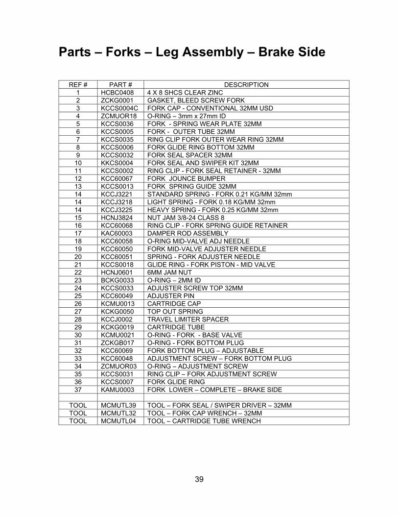
Parts – Forks – Leg Assembly – Brake Side
REF # PART # DESCRIPTION1 HCBC0408 4 X 8 SHCS CLEAR ZINC2 ZCKG0001 GASKET, BLEED SCREW FORK3 KCCS0004C FORK CAP - CONVENTIONAL 32MM USD4 ZCMUOR18 O-RING – 3mm x 27mm ID5 KCCS0036 FORK - SPRING WEAR PLATE 32MM6 KCCS0005 FORK - OUTER TUBE 32MM7 KCCS0035 RING CLIP FORK OUTER WEAR RING 32MM 8 KCCS0006 FORK GLIDE RING BOTTOM 32MM9 KCCS0032 FORK SEAL SPACER 32MM10 KKCS0004 FORK SEAL AND SWIPER KIT 32MM11 KCCS0002 RING CLIP - FORK SEAL RETAINER - 32MM 12 KCC60067 FORK JOUNCE BUMPER13 KCCS0013 FORK SPRING GUIDE 32MM14 KCCJ3221 STANDARD SPRING - FORK 0.21 KG/MM 32mm 14 KCCJ3218 LIGHT SPRING - FORK 0.18 KG/MM 32mm14 KCCJ3225 HEAVY SPRING - FORK 0.25 KG/MM 32mm15 HCNJ3824 NUT JAM 3/8-24 CLASS 816 KCC60068 RING CLIP - FORK SPRING GUIDE RETAINER 17 KAC60003 DAMPER ROD ASSEMBLY18 KCC60058 O-RING MID-VALVE ADJ NEEDLE19 KCC60050 FORK MID-VALVE ADJUSTER NEEDLE20 KCC60051 SPRING - FORK ADJUSTER NEEDLE21 KCCS0018 GLIDE RING - FORK PISTON - MID VALVE22 HCNJ0601 6MM JAM NUT23 BCKG0033 O-RING – 2MM ID24 KCCS0033 ADJUSTER SCREW TOP 32MM25 KCC60049 ADJUSTER PIN26 KCMU0013 CARTRIDGE CAP27 KCKG0050 TOP OUT SPRING28 KCCJ0002 TRAVEL LIMITER SPACER29 KCKG0019 CARTRIDGE TUBE30 KCMU0021 O-RING - FORK - BASE VALVE31 ZCKGB017 O-RING - FORK BOTTOM PLUG32 KCC60069 FORK BOTTOM PLUG – ADJUSTABLE33 KCC60048 ADJUSTMENT SCREW – FORK BOTTOM PLUG 34 ZCMUOR03 O-RING – ADJUSTMENT SCREW35 KCCS0031 RING CLIP – FORK ADJUSTMENT SCREW36 KCCS0007 FORK GLIDE RING37 KAMU0003 FORK LOWER – COMPLETE – BRAKE SIDE
TOOL MCMUTL39 TOOL – FORK SEAL / SWIPER DRIVER – 32MM TOOL MCMUTL32 TOOL – FORK CAP WRENCH – 32MMTOOL MCMUTL04 TOOL – CARTRIDGE TUBE WRENCH

40
Parts – Forks – Leg Assembly – Non-Brake Side

41
REF # PART # DESCRIPTION1 HCBC0408 4 X 8 SHCS CLEAR ZINC2 ZCKG0001 GASKET, BLEED SCREW FORK3 KCCS0004S FORK CAP – SMART LEG 32MM USD4 ZCMUOR18 O-RING PV SOLENOID - CX655 KCCS0036 FORK - SPRING WEAR PLATE 32MM6 KCCS0005 FORK - OUTER TUBE 32MM7 KCCS0035 RING CLIP FORK OUTER WEAR RING 32MM 8 KCCS0006 FORK GLIDE RING BOTTOM 32MM9 KCCS0032 FORK SEAL SPACER 32MM10 KCMZ0015 FORK SEAL - MARZ3211 KCCS0002 RING CLIP - FORK SEAL RETAINER - 32MM 12 KCC60067 FORK JOUNCE BUMPER13 KCCS0013 FORK SPRING GUIDE 32MM14 KCCJ3221 STANDARD SPRING - FORK 0.21 KG/MM 32mm 14 KCCJ3218 LIGHT SPRING - FORK 0.18 KG/MM 32mm 14 KCCJ3225 HEAVY SPRING - FORK 0.25 KG/MM 32mm 15 HCNJ3824 NUT JAM 3/8-24 CLASS 816 KCC60068 RING CLIP - FORK SPRING GUIDE RETAINER 17 KAC60003 DAMPER ROD ASSEMBLY18 KCC60058 O-RING MID-VALVE ADJ NEEDLE19 KCC60050 FORK MID-VALVE ADJUSTER NEEDLE 20 KCC60051 SPRING - FORK ADJUSTER NEEDLE21 KCCS0018 GLIDE RING - FORK PISTON - MID VALVE 22 HCNJ0601 6MM JAM NUT23 BCKG0033 O-RING – 2MM ID24 KCCS0033 ADJUSTER SCREW TOP 32MM25 KCC60049 ADJUSTER PIN26 KCMU0013 CARTRIDGE CAP27 KCKG0050 TOP OUT SPRING28 KCCJ0002 TRAVEL LIMITER SPACER29 KCKG0019 FORK - CARTRIDGE TUBE30 KCMU0021 O-RING - FORK - BASE VALVE31 KCC60057 PLUG – FORK BOTTOM – SMART LEG 32 KCCS0007 FORK GLIDE RING33 KAMU0004 FORK LOWER – COMPLETE – NON BRAKE SIDE
TOOL MCMUTL39 TOOL – FORK SEAL / SWIPER DRIVER – 32MM TOOL MCMUTL32 TOOL – FORK CAP WRENCH – 32MMTOOL MCMUTL04 TOOL – CARTRIDGE TUBE WRENCH
42
Parts – Frame – Mounting Hardware I
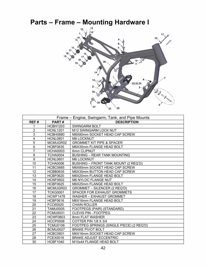
Frame – Engine, Swingarm, Tank, and Pipe Mounts REF # PART # DESCRIPTION
1 HCBH1203 SWINGARM BOLT2 HCNL1201 M12 SWINGARM LOCK NUT 3 HCBH0880 M8X80mm SOCKET HEAD CAP SCREW4 HCNL0801 M8 LOCKNUT5 MCMUGR02 GROMMET KIT PIPE & SPACER6 HCBF0635 M6X35mm FLANGE HEAD BOLT7 HCHA0003 6mm CLIPNUT8 TCHA0004 BUSHING – REAR TANK MOUNTING9 HCNL0601 M6 LOCKNUT10 TCHA0006 BUSHING – FRONT TANK MOUNT (2 REQ’D)11 HCBC0685 M6X85mm SOCKET HEAD CAP SCREW12 HCBB0635 M6X35mm BUTTON HEAD CAP SCREW13 HCBF0620 M6X20mm FLANGE HEAD BOLT14 HCNF0602 M6 NYLOC FLANGE NUT15 HCBF0625 M6X25mm FLANGE HEAD BOLT16 MCMUGR03 GROMMET – SILENCER (2 REQ’D)17 TCKG0001 SPACER FOR EXHAUST GROMMETS18 HCWF1478 WASHER – EXHAUST GROMMET19 HCBF0616 M6X16mm FLANGE HEAD BOLT20 FCC60020 CHAIN ROLLER21 TAMU0005 FOOTPEGS (PAIR) (STANDARD)22 FCMU0031 CLEVIS PIN - FOOTPEG 23 HCWF0803 8mm FLAT WASHER24 HCCP0008 COTTER PIN 1/8 X 3/425 TCMU0106 FOOTPEG SPRINGS (SINGLE PIECE) (2 REQ’D) 26 BCMU0027 BRAKE PIVOT BOLT27 HCBC0601 M6X16mm SOCKET HEAD CAP SCREW28 FCEX0018 BRAKE ADJUST ECCENTRIC30 HCBF1040 M10x44 FLANGE HEAD BOLT

43
Parts – Frame – Mounting Hardware II
Frame – Seat, Fender, Right Side Panel, Radiator & Shock Mounts REF # PART # DESCRIPTION
1 FACJ2019G FRAME CX50 JR/P3 2 EACJ0001 MOUNTING BRACKET – RADIATOR BOTTOM3 HCBC0608 M6X55mm SOCKET HEAD CAP SCREW4 HCNL0601 M6 LOCK NUT
5 MCKGGR00 GROMMET – RADIATOR MOUNT (2 REQ’D ON BOTTOM, 2 ON TOP BRACKET)
6 ECHA0109 MOUNTING BRACKET – RADIATOR TOP (2 REQ’D) 7 HCBC0665 M6X65mm SOCKET HEAD CAP SCREW8 HCBF0616 M6X16mm FLANGE HEAD BOLT9 HCHA0003 6mm CLIPNUT10 HCBH0502 M5X16mm HEX HEAD (2 REQ’D)11 HCWP0002 WASHER POP RIVET (2 REQ’D)

44
11
Parts – Front Brakes
Front BrakesREF# PART # DESCRIPTION
1 BAMU0007 BRAKE ASSY – FRONT CARD – JR/P32 BCMU0048 HOSE – BRAKE FRONT3 BAMU0009 LEVER ASSEMBLY – THIN FORMLY4 BAMU0006 MASTER CYLINDER ASSEMBLY 11.0 CARD5 BAMU0020 CALIPER – FRONT – CARD 2 PISTON6 BKMU0009 KIT 505 ORGANIC BRAKE PADS, WITH BOLT AND CLIP 7 BCMU0222 BRAKE ROTOR 8 HCBC0514 M5X14mm SOCKET HEAD CAP SCREW (5 REQ’D) 9 HCBC0604 M6X35mm SOCKET HEAD CAP SCREW10 HCBC0602 M6X20mm SOCKET HEAD CAP SCREW11 BCMU0116 COVER – MUD PROTECTION
Caliper Accessories ACCESSORY MCMUBF03 BRAKE FLUID – SPECTRO RACING DOT 4 –HIGH TEMP - 355 mlACCESSORY BKMU0003 BLEED KIT (MULTIPLE SYRINGES, FITTINGS & HOSE) ACCESSORY BCMU0038 SPRING - BRAKE PAD RETURNACCESSORY BKMU0006A PISTON & SEAL KIT – CARD - ALUMINUMACCESSORY BKMU0008 BLEED SCREW KIT – CARDACCESSORY BKMU0007 BANJO BOLT AND WASHER KIT – CARDACCESSORY BCMU0014 CALIPER ADJUSTMENT SHIMS 6mm IDMaster Cylinder Accessories ACCESSORY BKC60008 CAP & BLADDER KIT ZL150 (CAP, BLADDER & (2) M3-0.5 X 6mm LONG PHILLIPS SCREW)ACCESSORY BCC60058 CLAMP – M/C ZL150ACCESSORY HCBC0602 M6-1.0 X 22mm SOCKET HEAD CAP SCREWACCESSORY BCMU0060 PIVOT BOLT ACCESSORY BCC60017 BOOT – PISTON END COVERACCESSORY BKC60015 REBUILD KIT – MASTER CYLINDER CARD 11.0 mm ACCESSORY
(PISTON, SEALS, BUSHING, SPRING, CLIIP & RETAINING WASHER)
ACCESSORY HCSS0520 M5 X 20 SET SCREW – LEVER POSITON ADJUSTMENT ACCESSORY HCNJ0501 5MM LOCKNUTACCESSORY CKC60005 PIVOT BOLT KIT – LEVER TO PIVOT BLOCK – MALE & FEMALEACCESSORY HCSS0610 SET SCREW – PRESETACCESSORY BCMU0059 LEVER ONLY – THIN FORMLYACCESSORY CCC60026 SPRING – LEVER RETURNACCESSORY CCC60025 SPACER – SPRING CENTERING

45
Parts – Front Wheel
Front WheelREF # PART # DESCRIPTION
1 WAMUF020BLK WHEEL WITH BEARINGS SPOKE STYLE – BLACK ANODIZE2 WCMU0043 FRONT AXLE - HOLLOW3 HCSP1016M BOLT – ALUMINUM AXLE PULL4 WCMU0024 PLUG - BLACK PLASTIC5 HCBC0514 M5X14mm SOCKET HEAD CAP SCREW (5 REQ’D) 6 BCMU0222 BRAKE ROTOR – FRONT & REAR7 WCMU0045 WHEEL SPACER LEFT 8 WCMU0120 BEARING – WHEEL (2 REQ’D)9 WCMU0044 SPACER – WHEEL FRONT10 WCMUTU10 TUBE 10”11 WCMU1050D32 TIRE - FRONT - 60/100-10 - DUNLOP MX3S

46
Parts – Plastic & Seat

47
Parts – Plastic & Seat
Plastic and SeatREF # PART # DESCRIPTION
1 TCMU0034FLL FRONT FENDER – MEGA FLO YELLOW1 TCMU0034x FRONT FENDER x – DENOTES COLOR BLK, WHT, YEL, FLO
1A HCBF0616 FENDER BOLT, M6X16mm FLANGE HEAD (4 REQ’D) 2 TCC60002W NUMBER PLATE – FRONT2 TCC60002x FRONT PLATE x – DENOTES COLOR BLK, WHT, YEL
2A HCBF0616 M6X16mm FLANGE HEAD BOLT – FRONT NUMBER PLATE MOUNT
3 & 4 TCCJ0005FLL RADIATOR SHROUD SET (LEFT & RIGHT) – MEGA FLO YELLOW
3 & 4 TCCJ0005x RADIATOR SHROUD SET x - COLOR BLK, WHT, YEL, FLO
5 TCCJ0010C FUEL TANK – CLEAR – NO CAP OR PETCOCK – 2017 & NEWER
5A HCFH0625 M6X25mm PHILIPS HEAD SCREW – SEAT & SHROUD HOLD5B TCHA0005 SPACER – SEAT & SHROUD HOLD5C TCHA0006 SPACER – FRONT TANK MOUNT (2 REQ’D) 5D HCBC0685 M6X85mm SHCS – FRONT TANK MOUNT 5E HCNL0601 M6 LOCK NUT – FRONT TANK MOUNT BOLT 5F HCBC0685 M6X85mm SOCKET HEAD CAP SCREW5G TCHA0004 BUSHING – REAR TANK MOUNTING6 TCHA0002 CAP – FUEL TANK7 TCHA0003 HOSE – FUEL CAP8 TCMU0151 FUEL PETCOCK9 TCCM0007 SEAT
9A TCCM0007COVER SEAT COVER REPLACEMENT9B HCBC0604 M6X35mm SHCS – SEAT HOLDING9C MCMU0013 STRAP HANDLE
10 & 11 TCCJ0003W NUMBER PLATE SET (LEFT AND RIGHT) - WHITE 10 & 11 TCCJ0003x NUMBER PLATE SET x – DENOTES COLOR BLK, WHT, YEL
10A HCBF0616 M6X16mm FLANGE HEAD BOLT – FRONT SECURE
10B HCBF0620 M6X20mm FLANGE HEAD BOLT – FENDER & REAR SECURE
10C HCNF0602 M6 NYLOC FLANGE NUT10D HCBF0616 M6X16mm FLANGE HEAD BOLT – FRONT SECURE
10E HCBF0620 M6X20mm FLANGE HEAD BOLT – FENDER & REAR SECURE
10F HCNF0602 M6 NYLOC FLANGE NUT12 TCHA0112FLL FENDER – REAR – MEGA FLO YELLOW
12 TCHA0112x FENDER – REAR x – DENOTES COLOR BLK, WHT, YEL, MEGA FLO
12A HCBF0616 M6X16mm FLANGE HEAD BOLT – FENDER & AIRBOXACC’Y TCMU2020 GRAPHIC KITACC’Y TKCJ2019S BODYWORK KIT - JR - STOCKACC’Y TKCJ2019BLK BODYWORK KIT - JR - BLACKACC’Y TKCJ2019WHT BODYWORK KIT - JR - WHITEACC’Y TKCJ2019Y BODYWORK KIT - JR - YELLOWACC’Y TKCJ2019FLO BODYWORK KIT - JR – MEGA FLO YELLOW
48
Parts – Rear Brake
49
Parts – Rear Brake
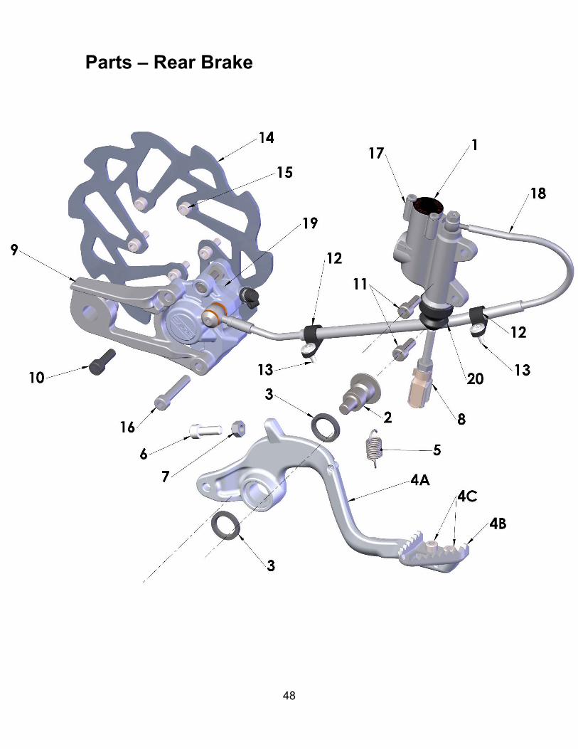
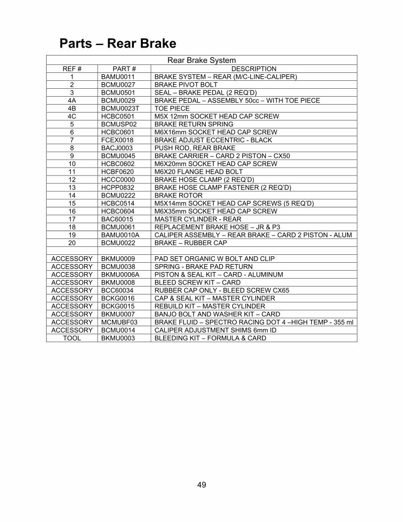
Rear Brake SystemREF # PART # DESCRIPTION
1 BAMU0011 BRAKE SYSTEM – REAR (M/C-LINE-CALIPER) 2 BCMU0027 BRAKE PIVOT BOLT3 BCMU0501 SEAL – BRAKE PEDAL (2 REQ’D)
4A BCMU0029 BRAKE PEDAL – ASSEMBLY 50cc – WITH TOE PIECE 4B BCMU0023T TOE PIECE4C HCBC0501 M5X 12mm SOCKET HEAD CAP SCREW5 BCMUSP02 BRAKE RETURN SPRING6 HCBC0601 M6X16mm SOCKET HEAD CAP SCREW7 FCEX0018 BRAKE ADJUST ECCENTRIC - BLACK8 BACJ0003 PUSH ROD, REAR BRAKE9 BCMU0045 BRAKE CARRIER – CARD 2 PISTON – CX50 10 HCBC0602 M6X20mm SOCKET HEAD CAP SCREW11 HCBF0620 M6X20 FLANGE HEAD BOLT 12 HCCC0000 BRAKE HOSE CLAMP (2 REQ’D)13 HCPP0832 BRAKE HOSE CLAMP FASTENER (2 REQ’D) 14 BCMU0222 BRAKE ROTOR 15 HCBC0514 M5X14mm SOCKET HEAD CAP SCREWS (5 REQ’D) 16 HCBC0604 M6X35mm SOCKET HEAD CAP SCREW17 BAC60015 MASTER CYLINDER - REAR18 BCMU0061 REPLACEMENT BRAKE HOSE – JR & P319 BAMU0010A CALIPER ASSEMBLY – REAR BRAKE – CARD 2 PISTON - ALUM20 BCMU0022 BRAKE – RUBBER CAP
ACCESSORY BKMU0009 PAD SET ORGANIC W BOLT AND CLIPACCESSORY BCMU0038 SPRING - BRAKE PAD RETURNACCESSORY BKMU0006A PISTON & SEAL KIT – CARD - ALUMINUM ACCESSORY BKMU0008 BLEED SCREW KIT – CARDACCESSORY BCC60034 RUBBER CAP ONLY - BLEED SCREW CX65 ACCESSORY BCKG0016 CAP & SEAL KIT – MASTER CYLINDERACCESSORY BCKG0015 REBUILD KIT – MASTER CYLINDERACCESSORY BKMU0007 BANJO BOLT AND WASHER KIT – CARDACCESSORY MCMUBF03 BRAKE FLUID – SPECTRO RACING DOT 4 –HIGH TEMP - 355 mlACCESSORY BCMU0014 CALIPER ADJUSTMENT SHIMS 6mm ID
TOOL BKMU0003 BLEEDING KIT – FORMULA & CARD
50
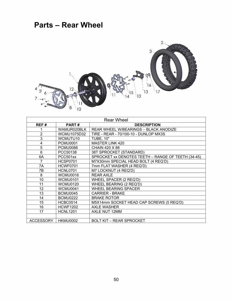
Parts – Rear Wheel
Rear WheelREF # PART # DESCRIPTION
1 WAMUR020BLK REAR WHEEL W/BEARINGS – BLACK ANODIZE 2 WCMU1075D32 TIRE - REAR - 70/100-10 - DUNLOP MX3S 3 WCMUTU10 TUBE, 10"4 PCMU0001 MASTER LINK 4205 PCMU0088 CHAIN 420 X 886 PCC50138 38T SPROCKET (STANDARD)
6A PCC501xx SPROCKET xx DENOTES TEETH – RANGE OF TEETH (34-45)7 HCSP0701 M7X30mm SPECIAL HEAD BOLT (4 REQ’D)
7A HCWF0701 7mm FLAT WASHER (4 REQ’D)7B HCNL0701 M7 LOCKNUT (4 REQ’D)8 WCMU0016 REAR AXLE10 WCMU0101 WHEEL SPACER (2 REQ’D)11 WCMU0120 WHEEL BEARING (2 REQ’D)12 WCMU0041 WHEEL BEARING SPACER 13 BCMU0045 CARRIER - BRAKE14 BCMU0222 BRAKE ROTOR15 HCBC0514 M5X14mm SOCKET HEAD CAP SCREWS (5 REQ’D) 16 HCWF1202 AXLE WASHER17 HCNL1201 AXLE NUT 12MM
ACCESSORY HKMU0002 BOLT KIT – REAR SPROCKET

51
Parts – Shock
Rear ShockREF# PART # DESCRIPTION
1 SACJ2012 SHOCK ABSORBER2 SCMU0043 SHOCK – BEARING SPERICAL SHOCK MOUNT – (2REQ’D)3 SCMU0039 O-RING – SHOCK – BUSHING (4 REQ’D)4 SCMU0042 SHOCK – MOUNT BUSHING (4 REQ’D)5 SCMU0058 SHOCK – WHITE NYLON TIP SET SCREW M6-1.0 6 SCMU0056 SHOCK – SLEEVE BLACK 7 SCCJ0004 BUMPER – JR - CARD SHOCK8 SCMU0040 SHOCK – SPRING PAD 9 SCMU0054 SHOCK SPRING PERCH10 SCMUOH05 SPRING – STANDARD (285 lb/in)10 SCMUOH04 SPRING – LIGHT (275 lb/in)10 SCMUOH06 SPRING – HEAVY (295 lb/in)11 HCBF1040 M10X40 FLANGE HEAD BOLT12 SCMU0330 RING -SPERICAL BEARING RETAINING -CARD SHOCKS13 SCMU0120 PRELOAD ADJUSTER – CARD SHOCK
ACCESSORY SKC60002 REBUILD KIT – CARD SHOCK
52
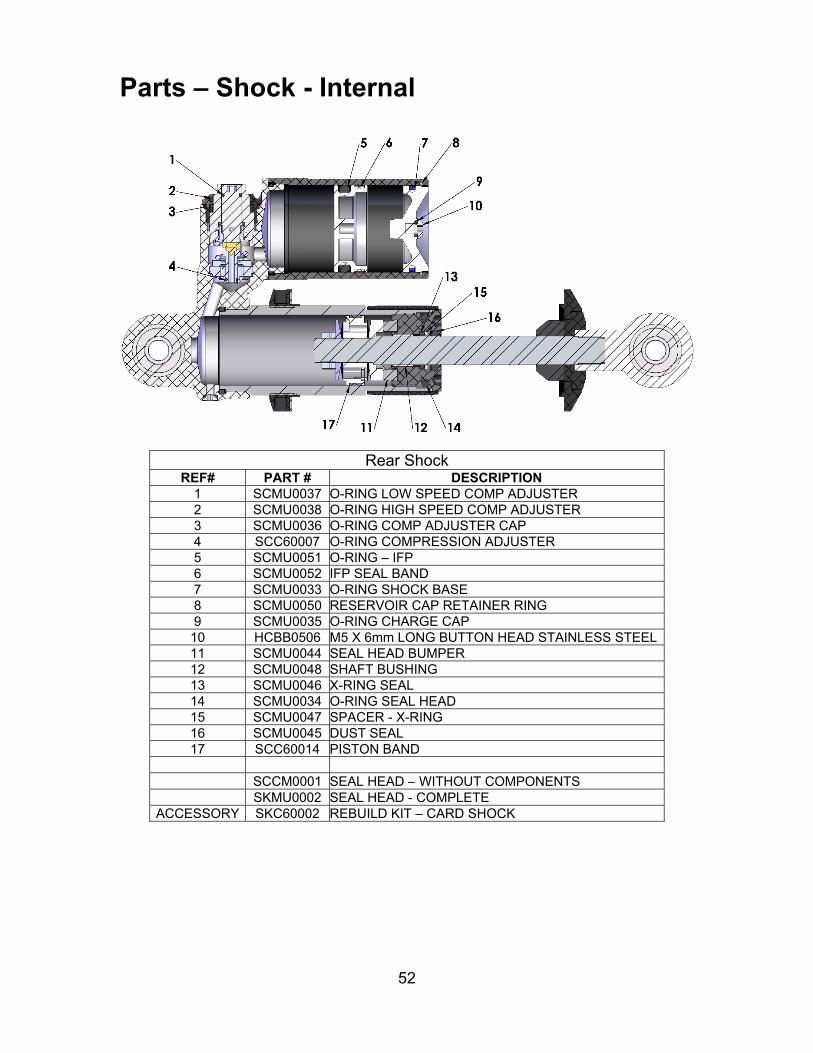
Parts – Shock - Internal
Rear ShockREF# PART # DESCRIPTION
1 SCMU0037 O-RING LOW SPEED COMP ADJUSTER 2 SCMU0038 O-RING HIGH SPEED COMP ADJUSTER 3 SCMU0036 O-RING COMP ADJUSTER CAP4 SCC60007 O-RING COMPRESSION ADJUSTER5 SCMU0051 O-RING – IFP6 SCMU0052 IFP SEAL BAND7 SCMU0033 O-RING SHOCK BASE8 SCMU0050 RESERVOIR CAP RETAINER RING9 SCMU0035 O-RING CHARGE CAP10 HCBB0506 M5 X 6mm LONG BUTTON HEAD STAINLESS STEEL11 SCMU0044 SEAL HEAD BUMPER12 SCMU0048 SHAFT BUSHING13 SCMU0046 X-RING SEAL14 SCMU0034 O-RING SEAL HEAD15 SCMU0047 SPACER - X-RING16 SCMU0045 DUST SEAL17 SCC60014 PISTON BAND
SCCM0001 SEAL HEAD – WITHOUT COMPONENTS SKMU0002 SEAL HEAD - COMPLETE
ACCESSORY SKC60002 REBUILD KIT – CARD SHOCK
53
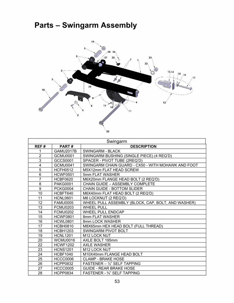
Parts – Swingarm Assembly
SwingarmREF # PART # DESCRIPTION
1 GAMU2017B SWINGARM - BLACK2 GCMU0001 SWINGARM BUSHING (SINGLE PIECE) (4 REQ’D) 3 GCCS0001 SPACER - PIVOT TUBE (2REQ’D)4 GCMU0041 SWINGARM CHAIN GUARD - CX50 - WITH MOHAWK AND FOOT5 HCFH0512 M5X12mm FLAT HEAD SCREW6 HCWF0501 5mm FLAT WASHER7 HCBF0620 M6X20mm FLANGE HEAD BOLT (2 REQ’D)8 PAKG0001 CHAIN GUIDE – ASSEMBLY COMPLETE9 PCKG0004 CHAIN GUIDE - BOTTOM SLIDER10 HCBFT640 M6X40mm FLAT HEAD BOLT (2 REQ’D)11 HCNL0601 M6 LOCKNUT (2 REQ’D)12 FAMU0005 WHEEL PULL ASSEMBLY (BLOCK, CAP, BOLT, AND WASHER)13 FCMU0203 WHEEL PULL14 FCMU0202 WHEEL PULL ENDCAP15 HCWF0801 8mm FLAT WASHER16 HCWL0801 8mm LOCK WASHER17 HCBH0810 M8X65mm HEX HEAD BOLT (FULL THREAD)18 HCBH1203 SWINGARM PIVOT BOLT19 HCNL1201 M12 LOCK NUT20 WCMU0016 AXLE BOLT 195mm22 HCWF1202 AXLE WASHER23 HCNS1201 M12 LOCK NUT24 HCBF1040 M10X40mm FLANGE HEAD BOLT25 HCCC0006 CLAMP - BRAKE HOSE26 HCPP0832 FASTENER – ½” SELF TAPPING27 HCCC0005 GUIDE - REAR BRAKE HOSE28 HCPP0834 FASTENER - ¾” SELF TAPPING

54
Service Trained technicians with precision gauging and proper assembly fixtures carefully assemble all Cobra engines to specific tolerances. If you feel you have the skills, and the appropriate tools, to perform the following service tasks please follow the instructions closely. The part numbers are listed throughout to help you when ordering parts from your local Cobra dealer. If you do not feel comfortable with the service work log on to: www.cobramoto.com to find a cobra dealer or call 517-437-9100.
Engine Service One method for determining whether the top end of your engine needs rebuilt is to perform a wide open throttle kicking compression test. Before performing the procedure please read the caution notes below. CAUTION: There is a large wide range of variability in reading compression gauges. The head volume of this Cobra Motorcycle is very small and requires 20 kicks
before you establish the most accurate reading possible. Because of the geometry of the spark plug used in this Cobra Motorcycle, the
adapter used with your compression tester must have a similar volume protruding into the combustion chamber to establish an accurate value.
Length of hose on the compression tester will affect the reading. The shorter
the hose length the more accurate your reading will be. Because of these difficulties in measuring an absolute compression value, a useful relative value can be achieved by testing your bike’s compression with your own particular gauge after a new top end or when the bike is new so that you know what your particular gauge reads on a ‘fresh’ engine. When it has dropped to 90% of its original value the engine will be down on power and would benefit from a rebuild. When it’s dropped to 80% it really needs rebuilt! Using the table below will help you determine monitor the condition of your top end.
Procedure for Compression Testing 1. Shut off the fuel petcock. 2. Install the compression gauge into the spark plug hole. 3. Hold the throttle wide open, and kick repeatedly (approximately 20 times) or until the gauge reading does not increase in value with each kick.
Engine is Fresh Measured Value
Engine Down on Power Measured Value * 0.9
Engine NEEDS Rebuilt Measured Value * 0.8
Example 110 psi 110 psi * 0.9 = 99 psi 110 psi * 0.8 = 88 psi Your Values

55
Base Gasket Selection Tools required 17mm wrench 1mm flexible solder material measurement calipers When rebuilding the ‘top end’ of your Cobra motorcycle, care must be taken to ensure the proper squish clearance. Squish clearance is defined as the minimum distance between cylinder head and piston at TDC, and there are negative effects of either having too much or too little clearance. Since parts like the crank, connecting rod, cylinder head, piston, and crankcases all have varying tolerances, Cobra offers several different base gasket thickness’ to ensure that you can always set the squish clearance of your engine to factory specifications. For base gasket replacement use the code (see figure 21 for location) along with the table on the following page reorder the correct thickness gasket.
Code Supplied Base
Gasket ThicknessCobra #
# mm inch Part #2 0.2 0.010 ZCMU01023 0.3 0.012 ZCMU01034 0.4 0.015 ZCMU01045 0.5 0.020 ZCMU01056 0.6 0.024 ZCMU01068 0.8 0.031 ZCMU0108
NOTE: Tolerances will affect the actual gasket thicknesses. If during the course of the maintenance more parts than the base gasket are changed, the squish clearance should be measured, and possibly a different base gasket will be required. The easiest way to measure squish clearance is with 1mm to 1.5mm thick flexible solder wire (available through most popular electronic stores). The process is as follows: Assemble the top end of the engine with either; 1) the crankcase stamp
recommended base gasket or, 2) if assembling with a new set of cases assemble with a 0.4mm (0.015”) base gasket, and torque the head nuts to the
Figure 21

56
proper torque specifications leaving off the spark plug and ignition cover (piston rings can be left off to ease of assembly).
Carefully insert the solder wire though the spark plug hole, into the cylinder far enough such that the tip of the wire touches the left or right side cylinder wall (not the front or back as the piston will rock more and give incorrect measurement).
Hold the wire at this position and rotate the crankshaft, by the flywheel nut (or kick lever) three revolutions to crush the solder wire.
CAUTION: If you rotate the flywheel nut in a counterclockwise direction there is a risk of loosening the nut. Pull out the wire and measure the solder thickness at the thinnest location
near its tip accurately with the thin tips of calipers. Adjust base gasket thickness as necessary to get the desired value. Upon completion, your final assembly squish clearance should agree with the chart below:
57
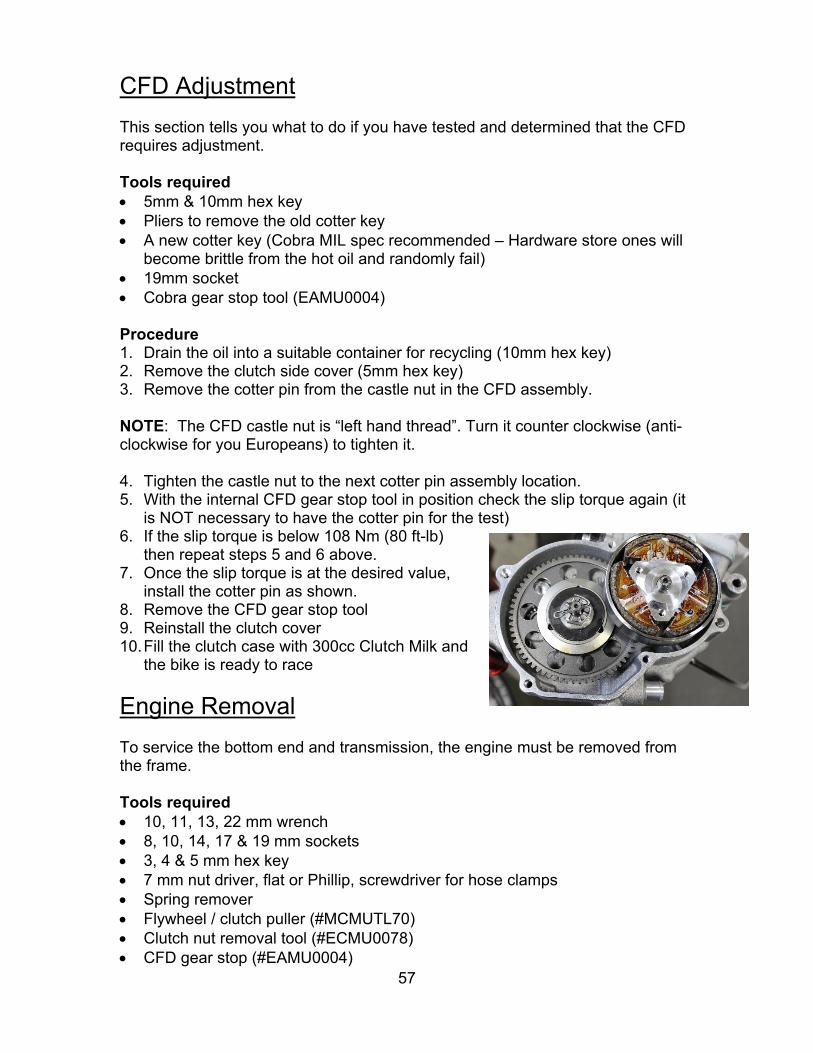
CFD Adjustment This section tells you what to do if you have tested and determined that the CFD requires adjustment. Tools required 5mm & 10mm hex key Pliers to remove the old cotter key A new cotter key (Cobra MIL spec recommended – Hardware store ones will
become brittle from the hot oil and randomly fail) 19mm socket Cobra gear stop tool (EAMU0004) Procedure 1. Drain the oil into a suitable container for recycling (10mm hex key) 2. Remove the clutch side cover (5mm hex key) 3. Remove the cotter pin from the castle nut in the CFD assembly.
NOTE: The CFD castle nut is “left hand thread”. Turn it counter clockwise (anti-clockwise for you Europeans) to tighten it.
4. Tighten the castle nut to the next cotter pin assembly location. 5. With the internal CFD gear stop tool in position check the slip torque again (it
is NOT necessary to have the cotter pin for the test) 6. If the slip torque is below 108 Nm (80 ft-lb)
then repeat steps 5 and 6 above. 7. Once the slip torque is at the desired value,
install the cotter pin as shown. 8. Remove the CFD gear stop tool 9. Reinstall the clutch cover 10. Fill the clutch case with 300cc Clutch Milk and
the bike is ready to race
Engine Removal To service the bottom end and transmission, the engine must be removed from the frame. Tools required 10, 11, 13, 22 mm wrench 8, 10, 14, 17 & 19 mm sockets 3, 4 & 5 mm hex key 7 mm nut driver, flat or Phillip, screwdriver for hose clamps Spring remover Flywheel / clutch puller (#MCMUTL70) Clutch nut removal tool (#ECMU0078) CFD gear stop (#EAMU0004)
58
Procedure 1. Remove the seat. 2. Turn of the fuel at the petcock and disconnect the fuel line. 3. Remove the tank (8 mm socket). 4. Remove the carburetor from the inlet (flat head or Phillips head screwdriver, 7
mm nut driver). 5. Remove the silencer & pipe (spring remover, 8mm socket). 6. Locate a suitable container for the engine coolant and disconnect the coolant
lines connected to the engine (8 mm socket). NOTE: If the coolant looks to be free of contaminates it may be reused. 7. Remove the master link from the chain. 8. Remove front engine mount bolt (13 mm socket, 6 mm hex key). 9. Remove the swingarm bolt (19mm socket). NOTE: Only drive the swingarm bolt far enough to clear the engine, leave it holding the one side of the swingarm to the frame 10. Remove the engine from the right side of the frame. NOTE: If you are merely performing a top end service skip ahead to Top End Disassembly Procedure.
Complete Engine Disassembly Procedure 1. Remove the ignition cover (3mm hex key) 2. Remove the bolt from the water pump shaft (4mm) and slide off the belt cover
and the water pump belt 3. Using a flywheel holding tool and 14 mm socket remove the nut that secures
the flywheel. 4. Using the Cobra flywheel / clutch puller (#MCMUTL70), remove the flywheel
from the crankshaft. 5. Remove the stator (4mm hex key). 6. Remove the clutch nut / starter gear that holds on the clutch (#ECMU0078). 7. With the Cobra flywheel / clutch puller (#MCMUTL70), remove the clutch from
the crankshaft (details in Clutch Service portion of this manual). 8. Remove the left hand thread nut holding the CFD to the transmission input
shaft using the CFD gear stop (#EAMU0004) and a 19mm socket.
Top End Disassembly Procedure 1. Remove the cylinder head nuts (10mm). 2. Remove the cylinder head outer.

59
3. Remove the cylinder head insert. 4. Remove the cylinder.
Muriatic acid can be dangerous. Follow the manufacturer’s instructions closely. 5. Remove the piston clip with a scribe. 6. Remove the piston pin with a piston pin remover. INSPECTION NOTE: Inspect the piston for abrasions and deposits on the top and sides and clean or replace as necessary. INSPECTION NOTE: Piston ring end gap should be between 0.008” (0.16 mm) and 0.015” (0.4 mm)
Splitting the Cases 1. Remove the fasteners holding the two halves of the crankcase together. 2. Separate the cases with a proper case splitting tools.
INSPECTION NOTE: Inspect the cylinder bore for abrasions, deposits, and missing coating.
1. If abrasions: scrapes, scratches, pitting, etc… are found, replace the cylinder.
2. If deposits are all are found a. Clean with muriatic acid. b. Once the deposits are removed, inspect for abrasions and missing
surface coating. i. If there are abrasions or missing coating, replace. ii. If all looks well, the cylinder may be saved.
INSPECTION NOTE: Inspect the cylinder head for deposits and abrasions.
1. If there are deposits they should be removed a. Black oily deposits (indicating a rich mixture or improper oil
type/quantity) can be removed with solvent b. Crusty deposits (indicating dirt ingestion) can be removed with
solvent and may require some scraping. 2. Abrasions
a. Pitting or erosion indicates detonation and may require cylinder head replacement, also
i. Retard the ignition timing ii. Use a higher octane fuel
b. Missing chunks or indentations indicate broken hardware or ingested items - replace the cylinder head.
60
CAUTION: Take caution when handling the crankshaft. It is the main power transfer to the rest of the engine. If it is out of alignment, it will cause premature failure of your bearings which can lead to serious damage to the cylinder as well as the rest of the engine. Do not try to true the crank yourself. Truing the crank should be done professionally. CAUTION: If you split the cases, check the gear tooth faces for chipping & signs of fatigue. Check all the bearing for smooth noise free operation.
Engine assembly CAUTION: For any seals that are to be installed, apply a light amount of grease to the seals’ ID, assembly lube on all bearings and a small amount of Loctite to the OD. 1. Press the three bearings into the respective holes in each case half. 2. Press in the crank seals such that the concave side faces the crank weights. 3. Press in the counter shaft seal (concave side faces inside of transmission) 4. Press in the water pump assembly 5. Tap both ways axially then verify easy rotation. 6. Inspect the crankshaft for proper true geometry (no more than 0.002 “,
0.05mm, measured at bearing journal area while supported from the ends). 7. Insert the case bolts with the proper lengths at locations shown. 8. Torque to 12Nm (105in-lb). Starting toward the center working outward. 9. Trim away any excess gasket material if necessary. NOTE: Check engine mount holes for excess material that may cause problems in engine installation. 10. Install the piston with new wrist pin bearing and, pin and clips. CAUTION: Be sure to install the piston such that the arrow on the top piston surface points to the exhaust (front of bike/engine) and put assembly lube on the connecting rod bearing. 11. Install the piston rings. CAUTION: Ring end gap should be no less than 0.008” (0.20mm) and no more than 0.015” (0.4mm). 12. Install the base gasket. CAUTION: See base gasket selection at the beginning of service section.

61
13. Install the cylinder being sure that the piston rings are properly aligned with
the indexing pins. CAUTION: Never force the cylinder. If resistance is felt, determine the problem and solve it. Once installed slightly rotate the cylinder back and forth insuring that the rings are properly seated. 14. Install cylinder head insert. NOTE: A light application of silicone grease can help hold the O-rings into position during assembly. 15. Install O-RINGs as shown in the Parts-Engine Top End page. 16. Install the cylinder head. 17. Install the flange nuts. Torque to 123 in-lb (14 Nm) 18. Install reed and intake manifold with new gasket. Torque to 55 in-lb. (6.2
Nm). CAUTION: The intake manifold bolts will require being checked and torque values reset after a few heat cycles. 19. Leak check the engine to 20 psi to ensure proper seal. 20. Install stator reinstalling the grommet and wires (snug the bolts). 21. Install the rotor per Rotor Installation section, under the S3: Ignition portion of
this manual. 22. If necessary install the water pump outlet pipe (apply gray Permatex gasket
maker to the threads before assembly). 23. Install the CFD. 24. Install the clutch per Clutch Installation section in this manual. 25. Install the coolant drain plug. 26. Make sure that the exhaust spacer is on the cylinder (53 in-lb, 6 Nm). 27. Install the spark plug with a fresh gasket (to apply the proper torque to the
spark plug when inserting, one must first screw the spark plug in until the metal gasket ring causes resistance and then turn another 1/8 to ¼ turn).
Clutch The sleeve bolts of the 5GX provide a low uniform stress, minimal heat transfer, and allow channels for flushing the clutch fibers out of the washer stacks allowing a long time between part replacement provided you operate with 10 oz of clean Clutch Milk. All washer stacks are double sorted at the factory. They are first sorted by measured height. Secondly, each stack with bolt is sorted by measured

62
engagement force. The stacks in each set of three will measure within 0.05mm (0.002”). There are many variables in an automatic centrifugal clutch. These variables are set to world class standards from the factory but will change over time as the components wear, relax, and just plain get used. Tools recommended for clutch service: Universal clutch puller- a universal puller that pulls the clutch, main drive gear
and rotor. (Part # MCMUTL70). 5mm T-handle T25 Torx Accurate torque wrench in the range of 16 Nm (12 ft-lb, 144 in-lb). Clutch nut removal tool (ECMU0078) & piston stop (MCMUTL03). Cobra 3 Shoe Clutch Milk (Part # MCMUGF32). CLUTCH REMOVAL: 1. Drain the engine transmission oil and remove the clutch cover. 2. Remove the clutch nut (NOT left hand thread) on the end of the crankshaft with
the clutch nut removal tool. CAUTION: It is possible to cause damage to the piston when using the piston stop. Care must be used when removing and installing the clutch arbor and using the piston stop. 3. Attach the Universal Puller. There are three 6mm
clutch puller holes located on the ends of the center hub.
4. Install each of the 3 6mm x 55mmsocket head cap screws (clutch cover bolts can be used) until each is similarly snug and the puller looks square to the end of the crank
5. One at a time, tighten each of the 1/4 turn until the clutch 'pops' off
NOTE: It may be helpful to use a screwdriver or similar device in the side hole of the puller to stop rotation CAUTION: Do not use a jaw type puller. CLUTCH WASHER STACKUPS: Once the clutch is removed, and cool to touch, carefully put it into a vice and remove the center shoulder bolt out of each clutch shoe. You WILL have to heat the center hub again to remove the bolts. Once you get a bolt loosened, carefully remove it with the shoe and observe the way the spring washers are stacked. Clean the washers and bolt if you intend to reuse.

63
CAUTION: You should apply heat to the arbor near the clutch bolt threads or you will very likely break the Torx bit upon attempted removal. CAUTION: It is easy to prematurely damage the clutch and other engine components with improper clutch adjustment. If you are unsure of how to adjust the clutch, contact the Cobra Technical Support Group before making adjustments. Clutch shoe wear: This can be measured by the overall diameter of the shoes installed on the
arbor. This measurement should be greater than 80.5mm If the clutch has been slipping and shows signs of glazing, it is best to replace
the shoes. We have found that once the shoes are glazed, even if deglazed with emery paper or a file, the performance is reduced.
The best way to prevent glazing is by not gearing too high, changing the oil as specified and by not blipping the throttle. Every time you blip the throttle, you are working your clutch springs.
Clutch basket wear: The internal diameter of a new clutch basket should measure ˜84.10mm. Over
time the clutch shoes will wear the internal surface down creating a bigger ID and causing a later engagement. The maximum ID we recommend to allow is 84.25mm.
CAUTION: The clutch produces a tremendous amount of heat and when a rider is blipping the throttle. This makes the clutch and clutch springs wear out quicker. This also makes your engine tend to run hotter which decreases engine power. It is important to train your rider NOT to be a throttle 'blipper'.
CLUTCH ASSEMBLY: 1. Start with a new set of pre- assembled washer stacks or a cleaned,
reassembled set of washer stacks and bolts. CAUTION: It is also important that all three shoes are stacked the same. (See figure 32) 2. Clean the threads of the stack bolt and the clutch with brake cleaner removing
all old thread locking material. 3. Assemble the stacks and shoes on the arbor using high strength thread lock
material to the stack bolt and tighten to 16 Nm (12 ft-lb, 144 in-lb). CAUTION: Avoid allowing excess thread lock material to contact the spring washers and the clutch or the clutch is likely to malfunction.

64
4. Clean the threads of the crank shaft and the clutch nut. 5. Install the clutch arbor on the crank. Making sure that the backing spacer in
place on the crank. 6. Apply high strength thread locking agent to the threads and install the clutch
nut and torque to 40 ft-lb (54Nm).
7. Install the clutch cover tightening the bolts from inside out. (8 or 10 mm socket, 5.8 ft-lb, 7.8 Nm).
NOTE: To ensure proper engagement of the kick gear with the starter nut, tighten the six screws only to the point of being not extremely loose. Using one hand rotate the kick lever to ½ stroke and hold while tightening the six screws completely with the other hand. 8. Fill with oil 300 cc (10.0 oz) Cobra 3 Shoe Clutch Milk (Part # MCMUGF32).
Ignition
Stator care Stator failure could result from running the bike hot. Following is a list of things that will make your engine run hot. 1. The timing should not exceed the maximum specifications listed. 2. Improper carburetor jetting. 3. Improper spark plug heat range. Never run a hotter plug than the specified
spark plug. 4. Clutch slippage. See “CLUTCH” section for causes of slippage. CAUTION: Because of the amount of heat generated by the clutch and engine during
extended periods of riding, it is advisable to remove the ignition cover afterward to allow the ignition to cool off. The heat transfers through the cases and can damage the stator as it cools off because of lack of airflow around the stator.
Ignition will overheat if the gap between the rotor and stator is not large enough. There should be even clearance as the rotor rotates relative to the stator.
INSPECTION NOTE: There must be in / out play in installed clutch, 0.3mm to 1.0 mm
(0.012” to 0.040”). This should be adjusted with the ECMU0040T and ECMU0040
shims A blue clutch drum is worn out from excessive slippage or improper
lubrication.

65
Ignition timing is not adjustable. Changing the ignition timing can degrade performance.
Make sure connections are free of dirt. CAUTION: Advancing the ignition timing will cause the engine to run hotter, in-turn causing power loss, shortened clutch life, and possibly lead to premature stator failure, and can also cause detonation which can lead to premature piston and ring failure. Tools recommended for timing service: Compact motorcycle dial indicator (ECMU0079) Universal clutch puller- a universal puller that pulls the clutch, main drive gear
and rotor. (Part # MCMUTL70).
CONFIRM YOUR IGNITION TIMING: 1. Remove the spark plug. 2. Insert the dial indicator into the spark plug hole. 3. Remove the four bolts from the ignition cover. 4. Remove the water pump belt from the rotor and water pump shaft. 5. Turn the crankshaft counterclockwise until it reaches top dead center. 6. Set the dial indicator to zero 7. Turn the crankshaft clockwise until the dial indicator reaches 0.040” (1.0 mm)
from top dead center. 8. At this position the line on the rotor should align with the center of the stator
coil at 5 o’clock position on stator frame. If not loosen the three 5mm bolts to adjust the stator.
ROTOR INSTALLATION: 1. Torque the nut on the rotor to 30 ft-lb (45 Nm) with medium strength (blue)
thread locking agent. 2. Recheck the timing following the procedure of timing your ignition. 3. Install the water pump belt back on. 4. Bolt the ignition cover back on. 5. Put the spark plug back in, and firmly stick the spark plug cap onto the spark
plug.
Cooling System Radiator fluid removal: Remove the coolant drain plug (10mm hex key) on the bottom of the engine cases. NOTE: Inspect the old coolant for evidence of oil, combustion byproducts (black ‘oil slick’ stuff) or other things that may indicate a problem.

66
Tools recommended for impeller service: Flat head screwdriver 2.5mm hex key 3mm hex key 4mm hex key 10mm hex key Water Pump Installation tool - MCMUTL08B Slide hammer with fitting to thread into threads on end of shaft (M6x1.0) single and double hook ends for removing plastic impeller Hammer
COBRA IMPELLER SERVICE INSTRUCTIONS 1. Remove radiator cap and drain engine coolant as described above.
NOTE: If the impeller is damaged or broken completely back flush the coolant system to ensure no solid pieces are in the system.
2. Remove ignition cover and water pump cover using a 3mm hex key
3. Using a 3mm hex key, remove the screw in the water pump shaft stop hole.
4. Stick a 2.5mm hex key in the water pump shaft cross hole, and remove belt retainer screw using a 4mm hex key. (Figure 41 - item 1)
5. Remove belt retainer, water pump belt and water pump fan pulley.
6. Remove bearing retainer screw using a 3mm hex key.
7. Thread a slide hammer onto the end of the water pump shaft and remove the assembly.
8. Clean any debris or particles from the bore and use some light emery cloth to remove any scratches in the surface that the removal process may have created.
9. Lubricate the bore with grease.
10. Prepare for assembly by installing the water pump assembly into the assembly tool and align the tool with engine case making sure alignment pin is in proper hole.

67
CAUTION: Damage may occur if one attempts to install the water pump assembly and it’s not aligned correctly in the bore. 11. Holding the tool squarely over the water pump assembly tap it firmly into place.
12. The assembly is installed properly when the retaining screw can be tightened
and it does not cause a bind on the spinning shaft (use medium strength thread lock on the retainer screw).
NOTE: It may be necessary to tap the outer bearing race in (hammer & blunt punch) or out (with slide hammer) to insure proper free operation of the shaft while the screw is tight. 13. Reinstall the pulley, belt and fan cover using a 2.5mm hex key to stop the
rotation of the water pump assembly while tightening with medium strength thread lock to 10 ft-lb (14Nm).
14. Reinstall the covers NOTE: Refill the coolant system with 50/50 antifreeze-coolant / distilled water. CAUTION: Do not mix Propylene Glycol based coolant / antifreeze solutions with Ethylene Glycol based coolant / antifreeze solutions.
Fuel & Air System
Carburetor Tools recommended for carburetor service: Small flat head screwdriver WD-40 8mm socket Your Cobra is equipped with an adjustable carburetor. Some fine-tuning may be needed according to weather condition and altitude. Proper jetting is very important for engine performance and engine life. Serious damage to the engine can occur if not properly adjusted. IDLE ADJUSTMENT: On the left side of the carburetor, there are two adjustment screws. The larger screw with the knurled head is the idle adjustment screw. To raise the idle, turn the screw in clockwise (in 1/4 turn increments) and rev the engine after each adjustment. To lower the idle, turn the screw counter-clockwise.
68
TOP END JETTING: Indications that the engine is running too rich (too much fuel for the air) are: Engine not revving out or blubbering at high RPMs. Engine will not ‘clean out’ Wet or black spark plug NOTE: Before changing jetting be sure that the air filter is properly cleaned and has the usual amount of air filter oil. An overly dirty air filter can cause the engine to run rich. If the engine is running rich on the top end it should be leaned out. Leaning it out can be done by: 1. Changing the main jet to a smaller number. 2. Raising the needle clip (this lowers the jet needle) one notch at a time on the
slide. Indications that the engine is running too lean are: Engine cutting out on top end. Engine overheating and ultimately seizure. White spark plug CAUTION: It is much safer to operate the engine slightly rich as opposed to slightly lean. This is because an overly rich engine will just run poorly while an overly lean engine will seize, potentially causing an expensive top end rebuild and a DNF. To richen the carburetor: 1. Change the main jet one number at a time (larger). 2. Lower the needle clip (raising the jet needle) one notch at a time until the engine
starts to blubber on the top end, then move the clip back up one notch or until you get the blubber out.
FUEL MIXTURE SCREW The smaller brass screw that is towards the front of the engine is a fuel mixture screw. This screw will also richen and lean your engine more on the bottom and mid-range. In warmer conditions, turn the screw in. In colder conditions, turn the screw out. Be sure to keep the carburetor very clean and make sure you don't have water or dirt in the carburetor bowl. Use automotive carburetor cleaner or WD-40 to clean the carburetor inside and out. Cleaning the carburetor:
Clean the carburetor in a well-ventilated area, and take care that there is no spark or flame anywhere near the working area; this includes any appliance with a pilot light. Because of the danger of highly flammable liquids, do not use gasoline or low flash-point solvent to clean the carburetor.
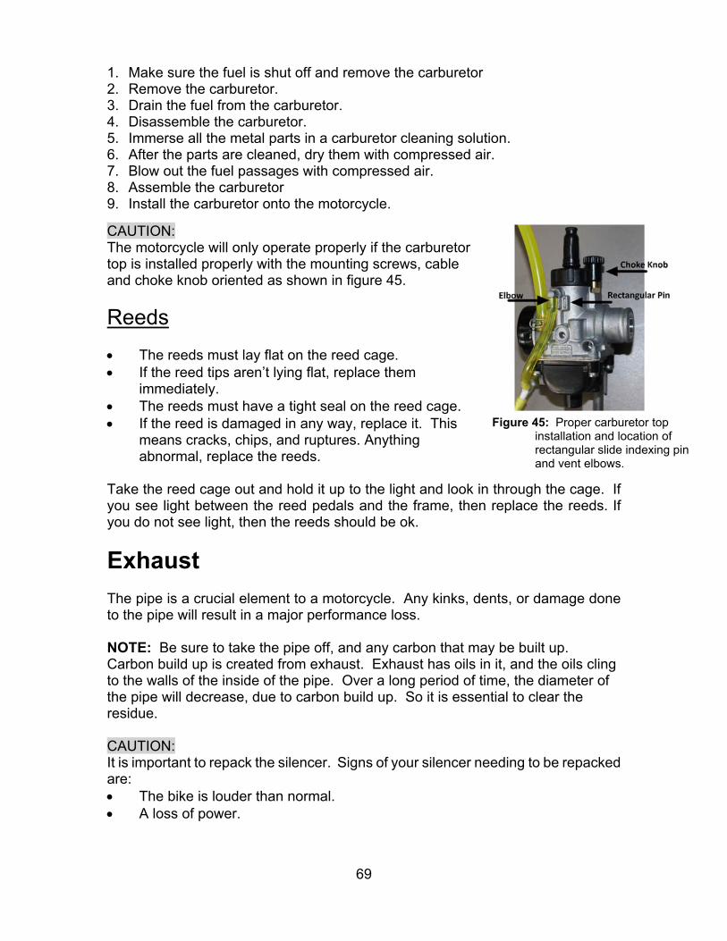
69
1. Make sure the fuel is shut off and remove the carburetor 2. Remove the carburetor. 3. Drain the fuel from the carburetor. 4. Disassemble the carburetor. 5. Immerse all the metal parts in a carburetor cleaning solution. 6. After the parts are cleaned, dry them with compressed air. 7. Blow out the fuel passages with compressed air. 8. Assemble the carburetor 9. Install the carburetor onto the motorcycle.
CAUTION: The motorcycle will only operate properly if the carburetor top is installed properly with the mounting screws, cable and choke knob oriented as shown in figure 45.
Reeds The reeds must lay flat on the reed cage. If the reed tips aren’t lying flat, replace them
immediately. The reeds must have a tight seal on the reed cage. If the reed is damaged in any way, replace it. This
means cracks, chips, and ruptures. Anything abnormal, replace the reeds.
Take the reed cage out and hold it up to the light and look in through the cage. If you see light between the reed pedals and the frame, then replace the reeds. If you do not see light, then the reeds should be ok.
Exhaust The pipe is a crucial element to a motorcycle. Any kinks, dents, or damage done to the pipe will result in a major performance loss. NOTE: Be sure to take the pipe off, and any carbon that may be built up. Carbon build up is created from exhaust. Exhaust has oils in it, and the oils cling to the walls of the inside of the pipe. Over a long period of time, the diameter of the pipe will decrease, due to carbon build up. So it is essential to clear the residue. CAUTION: It is important to repack the silencer. Signs of your silencer needing to be repacked are: The bike is louder than normal. A loss of power.
Figure 45: Proper carburetor top installation and location of rectangular slide indexing pin and vent elbows.
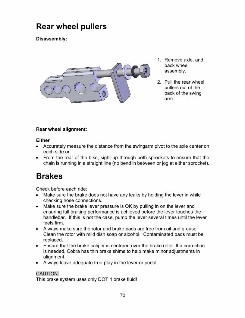
70
Rear wheel pullers Disassembly:
Rear wheel alignment: Either Accurately measure the distance from the swingarm pivot to the axle center on
each side or From the rear of the bike, sight up through both sprockets to ensure that the
chain is running in a straight line (no bend in between or jog at either sprocket).
Brakes Check before each ride: Make sure the brake does not have any leaks by holding the lever in while
checking hose connections. Make sure the brake lever pressure is OK by pulling in on the lever and
ensuring full braking performance is achieved before the lever touches the handlebar. If this is not the case, pump the lever several times until the lever feels firm.
Always make sure the rotor and brake pads are free from oil and grease. Clean the rotor with mild dish soap or alcohol. Contaminated pads must be replaced.
Ensure that the brake caliper is centered over the brake rotor. It a correction is needed, Cobra has thin brake shims to help make minor adjustments in alignment.
Always leave adequate free-play in the lever or pedal. CAUTION: This brake system uses only DOT 4 brake fluid!
1. Remove axle, and back wheel assembly.
2. Pull the rear wheel
pullers out of the back of the swing arm.
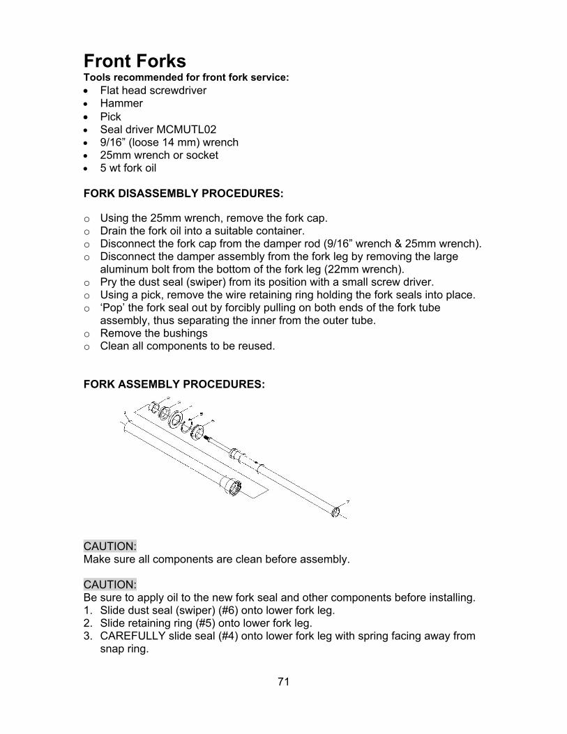
71
Front Forks Tools recommended for front fork service: Flat head screwdriver Hammer Pick Seal driver MCMUTL02 9/16” (loose 14 mm) wrench 25mm wrench or socket 5 wt fork oil FORK DISASSEMBLY PROCEDURES:
o Using the 25mm wrench, remove the fork cap. o Drain the fork oil into a suitable container. o Disconnect the fork cap from the damper rod (9/16” wrench & 25mm wrench). o Disconnect the damper assembly from the fork leg by removing the large
aluminum bolt from the bottom of the fork leg (22mm wrench). o Pry the dust seal (swiper) from its position with a small screw driver. o Using a pick, remove the wire retaining ring holding the fork seals into place. o ‘Pop’ the fork seal out by forcibly pulling on both ends of the fork tube
assembly, thus separating the inner from the outer tube. o Remove the bushings o Clean all components to be reused.
FORK ASSEMBLY PROCEDURES:
CAUTION: Make sure all components are clean before assembly. CAUTION: Be sure to apply oil to the new fork seal and other components before installing. 1. Slide dust seal (swiper) (#6) onto lower fork leg. 2. Slide retaining ring (#5) onto lower fork leg. 3. CAREFULLY slide seal (#4) onto lower fork leg with spring facing away from
snap ring.
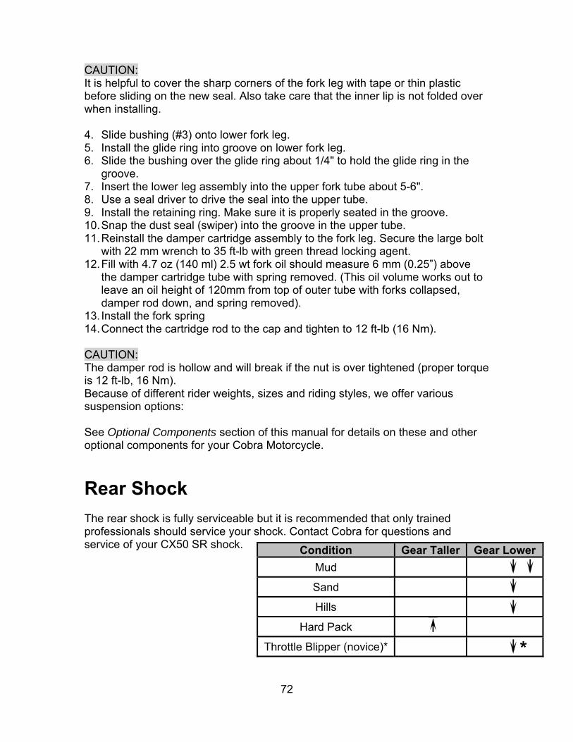
72
CAUTION: It is helpful to cover the sharp corners of the fork leg with tape or thin plastic before sliding on the new seal. Also take care that the inner lip is not folded over when installing. 4. Slide bushing (#3) onto lower fork leg. 5. Install the glide ring into groove on lower fork leg. 6. Slide the bushing over the glide ring about 1/4" to hold the glide ring in the
groove. 7. Insert the lower leg assembly into the upper fork tube about 5-6". 8. Use a seal driver to drive the seal into the upper tube. 9. Install the retaining ring. Make sure it is properly seated in the groove. 10. Snap the dust seal (swiper) into the groove in the upper tube. 11. Reinstall the damper cartridge assembly to the fork leg. Secure the large bolt
with 22 mm wrench to 35 ft-lb with green thread locking agent. 12. Fill with 4.7 oz (140 ml) 2.5 wt fork oil should measure 6 mm (0.25”) above
the damper cartridge tube with spring removed. (This oil volume works out to leave an oil height of 120mm from top of outer tube with forks collapsed, damper rod down, and spring removed).
13. Install the fork spring 14. Connect the cartridge rod to the cap and tighten to 12 ft-lb (16 Nm). CAUTION: The damper rod is hollow and will break if the nut is over tightened (proper torque is 12 ft-lb, 16 Nm). Because of different rider weights, sizes and riding styles, we offer various suspension options: See Optional Components section of this manual for details on these and other optional components for your Cobra Motorcycle.
Rear Shock The rear shock is fully serviceable but it is recommended that only trained professionals should service your shock. Contact Cobra for questions and service of your CX50 SR shock.
Condition Gear Taller Gear Lower
Mud Sand Hills
Hard Pack Throttle Blipper (novice)* *
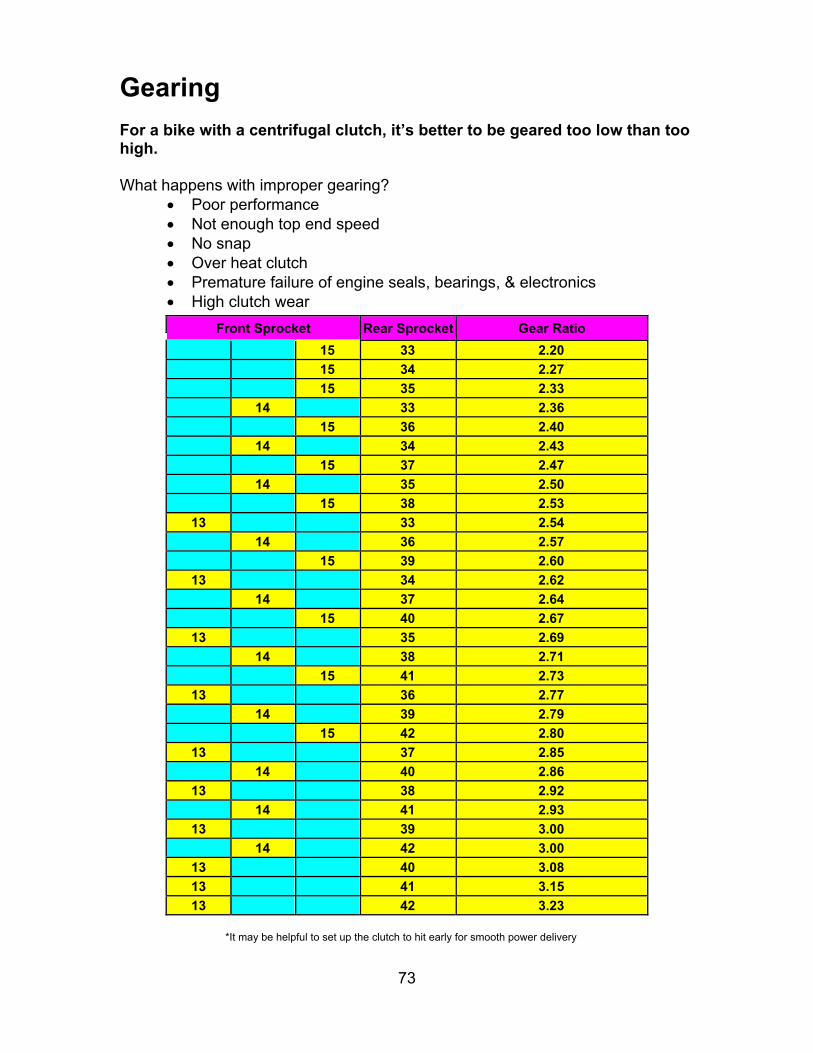
73
Gearing For a bike with a centrifugal clutch, it’s better to be geared too low than too high. What happens with improper gearing?
Poor performance Not enough top end speed No snap Over heat clutch Premature failure of engine seals, bearings, & electronics High clutch wear
Front Sprocket Rear Sprocket Gear Ratio
15 33 2.20
15 34 2.27
15 35 2.33
14 33 2.36
15 36 2.40
14 34 2.43
15 37 2.47
14 35 2.50
15 38 2.53
13 33 2.54
14 36 2.57
15 39 2.60
13 34 2.62
14 37 2.64
15 40 2.67
13 35 2.69
14 38 2.71
15 41 2.73
13 36 2.77
14 39 2.79
15 42 2.80
13 37 2.85
14 40 2.86
13 38 2.92
14 41 2.93
13 39 3.00
14 42 3.00
13 40 3.08
13 41 3.15
13 42 3.23
*It may be helpful to set up the clutch to hit early for smooth power delivery
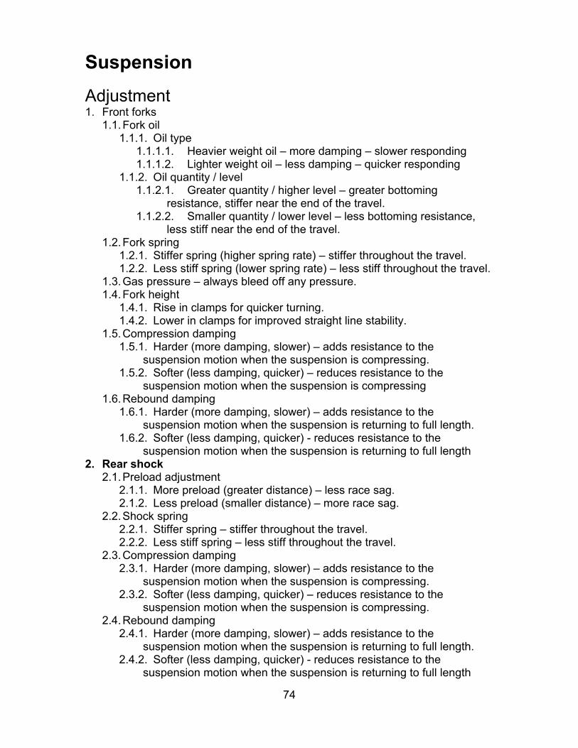
74
Suspension
Adjustment 1. Front forks
1.1. Fork oil 1.1.1. Oil type
1.1.1.1. Heavier weight oil – more damping – slower responding 1.1.1.2. Lighter weight oil – less damping – quicker responding
1.1.2. Oil quantity / level 1.1.2.1. Greater quantity / higher level – greater bottoming
resistance, stiffer near the end of the travel. 1.1.2.2. Smaller quantity / lower level – less bottoming resistance,
less stiff near the end of the travel. 1.2. Fork spring
1.2.1. Stiffer spring (higher spring rate) – stiffer throughout the travel. 1.2.2. Less stiff spring (lower spring rate) – less stiff throughout the travel.
1.3. Gas pressure – always bleed off any pressure. 1.4. Fork height
1.4.1. Rise in clamps for quicker turning. 1.4.2. Lower in clamps for improved straight line stability.
1.5. Compression damping 1.5.1. Harder (more damping, slower) – adds resistance to the
suspension motion when the suspension is compressing. 1.5.2. Softer (less damping, quicker) – reduces resistance to the
suspension motion when the suspension is compressing 1.6. Rebound damping
1.6.1. Harder (more damping, slower) – adds resistance to the suspension motion when the suspension is returning to full length.
1.6.2. Softer (less damping, quicker) - reduces resistance to the suspension motion when the suspension is returning to full length
2. Rear shock 2.1. Preload adjustment
2.1.1. More preload (greater distance) – less race sag. 2.1.2. Less preload (smaller distance) – more race sag.
2.2. Shock spring 2.2.1. Stiffer spring – stiffer throughout the travel. 2.2.2. Less stiff spring – less stiff throughout the travel.
2.3. Compression damping 2.3.1. Harder (more damping, slower) – adds resistance to the
suspension motion when the suspension is compressing. 2.3.2. Softer (less damping, quicker) – reduces resistance to the
suspension motion when the suspension is compressing. 2.4. Rebound damping
2.4.1. Harder (more damping, slower) – adds resistance to the suspension motion when the suspension is returning to full length.
2.4.2. Softer (less damping, quicker) - reduces resistance to the suspension motion when the suspension is returning to full length
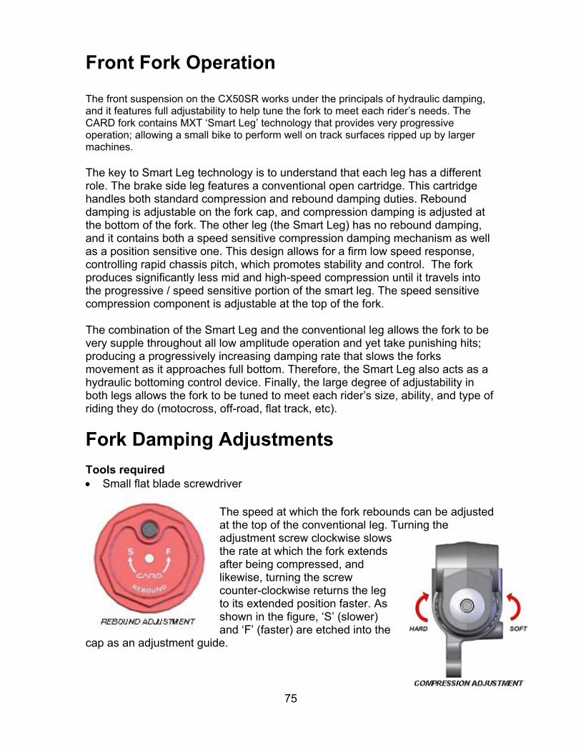
75
Front Fork Operation The front suspension on the CX50SR works under the principals of hydraulic damping, and it features full adjustability to help tune the fork to meet each rider’s needs. The CARD fork contains MXT ‘Smart Leg’ technology that provides very progressive operation; allowing a small bike to perform well on track surfaces ripped up by larger machines. The key to Smart Leg technology is to understand that each leg has a different role. The brake side leg features a conventional open cartridge. This cartridge handles both standard compression and rebound damping duties. Rebound damping is adjustable on the fork cap, and compression damping is adjusted at the bottom of the fork. The other leg (the Smart Leg) has no rebound damping, and it contains both a speed sensitive compression damping mechanism as well as a position sensitive one. This design allows for a firm low speed response, controlling rapid chassis pitch, which promotes stability and control. The fork produces significantly less mid and high-speed compression until it travels into the progressive / speed sensitive portion of the smart leg. The speed sensitive compression component is adjustable at the top of the fork. The combination of the Smart Leg and the conventional leg allows the fork to be very supple throughout all low amplitude operation and yet take punishing hits; producing a progressively increasing damping rate that slows the forks movement as it approaches full bottom. Therefore, the Smart Leg also acts as a hydraulic bottoming control device. Finally, the large degree of adjustability in both legs allows the fork to be tuned to meet each rider’s size, ability, and type of riding they do (motocross, off-road, flat track, etc).
Fork Damping Adjustments Tools required Small flat blade screwdriver
The speed at which the fork rebounds can be adjusted at the top of the conventional leg. Turning the adjustment screw clockwise slows the rate at which the fork extends after being compressed, and likewise, turning the screw counter-clockwise returns the leg to its extended position faster. As shown in the figure, ‘S’ (slower) and ‘F’ (faster) are etched into the
cap as an adjustment guide.

76
At the base of the conventional leg is another adjustment screw that controls the amount of compression damping. Turning this screw clockwise increases damping and turning it counter-clockwise will decrease it. This is illustrated by the “HARD” and “SOFT” in the figure at the right.
The Smart Leg cap is labeled “Speed Sensitive Bottoming Control”, and this adjuster provides a range of control over how progressive the fork feels. Turning the screw clockwise increases the fork’s resistance to bottoming, while turning the screw counter-clockwise decreases it. On the track, this effect will be felt on sections where the fork is forced to move very quickly such as on harsh landings or when traversing sharp edged bumps.
Symptom Action Rear end feels stiff on small bumps Softer compression damping Rear end ‘sways’ on straights Harder compression damping Bike tends to jump ‘rear end high’ Harder rebound damping Bike tends to jump ‘rear end low’ Softer rebound damping Frequent rear end bottoming Harder compression damping Bottoms after end of continuous bumps Softer rebound damping
Rear end ‘kicks’ over square edge bumps 1) Harder rebound, 2) Softer Compression
Rear Shock Adjustments Always start with standard settings and make damping changes in no more than two click increments and only make one change at a time.
Symptom Action
Rear end feels stiff on small bumps Softer Low Speed Compression Damping
Rear end ‘sways’ on straights Harder Low Speed Compression Damping
Bike tends to jump ‘rear end high’ Harder High Speed CompressionBike tends to jump ‘rear end low’ Softer High Speed CompressionFrequent rear end bottoming Harder Compression Damping Bottoms after end of continuous bumps Softer rebound damping
Rear end ‘kicks’ over square edge bumps 1) Harder rebound, 2) Softer Low and High Speed Compression
Rear end feels stiff under acceleration bumps.
Softer Rebound and/or Stiffer Low Speed Compression Damping

77
Proactive Suspension Adjustments Once you have the suspension adjusted for decent overall feel, you can make proactive adjustments when faced with different racing conditions.
Situation Actions Sand track Lower the rear end (increase race sag).Sand track Stiffer compression and rebound damping.Long fast track Lower the forks in the clamps by 3 mm.Tight slow track Raise the forks in the clamps by 3 mm.
Mud track Lower the bike if the rider has difficulties touching the ground.
Shock preload Loosen the set screw and turn the spring perch in full turn increments to get the desired sag settings.
NOTE: Always leave the spring perch rotated in such position so that the set screw is easily accessible.
Shock Damping
11. Adjustment of rebound damping 12. Adjustment of compression damping
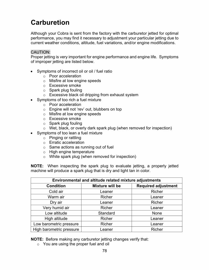
78
Carburetion Although your Cobra is sent from the factory with the carburetor jetted for optimal performance, you may find it necessary to adjustment your particular jetting due to current weather conditions, altitude, fuel variations, and/or engine modifications. CAUTION: Proper jetting is very important for engine performance and engine life. Symptoms of improper jetting are listed below. Symptoms of incorrect oil or oil / fuel ratio
o Poor acceleration o Misfire at low engine speeds o Excessive smoke o Spark plug fouling o Excessive black oil dripping from exhaust system
Symptoms of too rich a fuel mixture o Poor acceleration o Engine will not ‘rev’ out, blubbers on top o Misfire at low engine speeds o Excessive smoke o Spark plug fouling o Wet, black, or overly dark spark plug (when removed for inspection)
Symptoms of too lean a fuel mixture o Pinging or rattling o Erratic acceleration o Same actions as running out of fuel o High engine temperature o White spark plug (when removed for inspection)
NOTE: When inspecting the spark plug to evaluate jetting, a properly jetted machine will produce a spark plug that is dry and light tan in color.
Environmental and altitude related mixture adjustments Condition Mixture will be Required adjustment
Cold air Leaner Richer Warm air Richer Leaner Dry air Leaner Richer
Very humid air Richer Leaner Low altitude Standard None High altitude Richer Leaner
Low barometric pressure Richer Leaner High barometric pressure Leaner Richer
NOTE: Before making any carburetor jetting changes verify that:
o You are using the proper fuel and oil
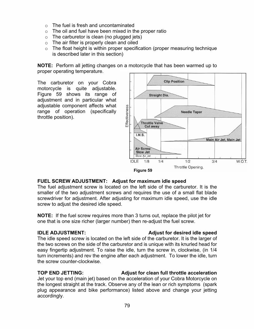
79
o The fuel is fresh and uncontaminated o The oil and fuel have been mixed in the proper ratio o The carburetor is clean (no plugged jets) o The air filter is properly clean and oiled o The float height is within proper specification (proper measuring technique
is described later in this section) NOTE: Perform all jetting changes on a motorcycle that has been warmed up to proper operating temperature. The carburetor on your Cobra motorcycle is quite adjustable. Figure 59 shows its range of adjustment and in particular what adjustable component affects what range of operation (specifically throttle position).
FUEL SCREW ADJUSTMENT: Adjust for maximum idle speed The fuel adjustment screw is located on the left side of the carburetor. It is the smaller of the two adjustment screws and requires the use of a small flat blade screwdriver for adjustment. After adjusting for maximum idle speed, use the idle screw to adjust the desired idle speed. NOTE: If the fuel screw requires more than 3 turns out, replace the pilot jet for one that is one size richer (larger number) then re-adjust the fuel screw. IDLE ADJUSTMENT: Adjust for desired idle speed The idle speed screw is located on the left side of the carburetor. It is the larger of the two screws on the side of the carburetor and is unique with its knurled head for easy fingertip adjustment. To raise the idle, turn the screw in, clockwise, (in 1/4 turn increments) and rev the engine after each adjustment. To lower the idle, turn the screw counter-clockwise. TOP END JETTING: Adjust for clean full throttle acceleration Jet your top end (main jet) based on the acceleration of your Cobra Motorcycle on the longest straight at the track. Observe any of the lean or rich symptoms (spark plug appearance and bike performance) listed above and change your jetting accordingly.
Figure 59

80
PART THROTTLE Adjust for desired acceleration Using an area of the track that allows the rider to operate and mid throttle and transition (accelerate, or ‘roll on’) from closed, or mostly closed throttle, to a larger throttle opening. Observe the rich and lean symptoms listed above. Adjust the jet needle position by moving the clip from its current position (move the clip higher on the needle to make the bike run leaner, or move the clip lower on the needle to make the bike run richer) to one higher or lower.
Troubleshooting 1) Engine not behaving properly
a) The carburetor slide indexing pin is missing
b) Wrong spark plug installed (8339 Champion to be used on ’04 or later & no
mods)
c) Needle clip is on top of plastic not below
d) Air leak – find where with carb cleaner or similar
e) Ground wire or ignition leads have fault
2) Engine is down on power
a) Clutch engagement is not set properly
b) Jetting is incorrect
c) Silencer needs repacked
d) Exhaust pipe
i) Has excess carbon buildup
ii) Has large dent in it
e) Compression is low
i) Piston
ii) Rings
f) Reeds are damaged
g) Ignition timing is incorrect
3) Engine is excessively loud
a) Silencer needs to be repacked
4) Engine cuts out at high RPMs
a) Stator bad
b) Carburetor diffuser plate upside down (install like a skirt)
c) Plugged fuel petcock
d) Silencer core tube broken

81
5) Engine won’t start
a) Fuel
i) None in tank
ii) Is sour or bad
b) Carburetor is dirty
c) Ignition
i) Spark plug fouled
ii) Wrong spark plug installed (8339 Champion to be used on ’04 or later & no
mods)
iii) Spark plug cap off
iv) Engine Shut-off ‘kill’ switch is shorted
v) Bad electrical ground
vi) Stator winding damaged
d) Exhaust is plugged
6) Overheating
a) Bad stator
b) Water pump pulleys or belt broken
c) Water pump impeller broken or bolt out
d) Jetting too lean
e) Too much throttle blipping
f) Too high gearing
g) Kinked radiator hose
h) Rear brake dragging
i) Chain too tight
j) Air leak
7) Engine won’t idle
a) Idle knob needs adjusted
b) Air leak
c) Carburetor jets are dirty