Embed Size (px)
Citation preview

Owner's ManualPlease read this manual before operating your battery charger
switch Mode, automatic, lead acid Battery Charger
MoDeLS:SeC-1215ULSeC-1230ULSeC-2415UL
2 | SAMLEX AMERICA INC.
Owner's Manual: Battery Chargers | Index
Section 1Safety Precautions ................................................................ 3
Section 2Layout .......................................................................... 4
Section 3Description, Features & Cooling ........................................... 7
Section 4Charging Stages & Protections ............................................. 8
Section 5Installation & Charger Operation ....................................... 10
Section 6Troubleshooting ................................................................. 15
Section 7Internal Fuse Rating & Specifications .................................. 17
Section 8Warranty ......................................................................... 18
2 | SAMLEX AMERICA INC. SAMLEX AMERICA INC. | 3
seCtIOn 1 | safety Precautions
Hazardous conditions may result if the charger is not installed or operat-ed correctly. Please read the following instructions to prevent personal injury or damage to the charger:
Battery Related
• Toreducetheriskofbatteryexplosion,followtheseinstructionsandthosemarkedonthebattery
• Neversmokeorallowanopenspark orflameinthevicinityofthebatteryorengine
• ChargeonlyLeadAcidtypeofbatteries(Flooded/AbsorbedGlassMat(AGM)/GelCell).DonotchargeothertypeofbatterieslikeNickelCadmium (NiCad)
• Nickel-MetalHydride(Ni-MH),Dry-Celletc.Othertypesofbatteriesmightburstcausing personal injury
• Neverchargeafrozenbattery
• WorkinginthevicinityofLeadAcidbat-teriesisdangerous.Batteriesgenerateexplosivegasesduringnormalopera-tion.Takenecessarysafetyprecautionswheninstallingthechargernearabattery or in a battery compartment (Followsafetyinstructionsgivenbythebatterymanufacturer)
• Neverplacethechargerdirectlyaboveorbelowthebatterybeingcharged;gasesorfluidsfromthebatterywillcor-rodeanddamagethecharger.Locatethechargerasfarawayfromthebat-teryasDCcablespermit.Donotinstallin the same compartmentas batteries
charger Related
• Donotoperatethechargerinaclosed-inareaorrestrictventilationinanyway.
• Installinawellventilated,cool, dryplace.
• Thechargermustnotbeoperatedinadamporwetenvironment.Whenmountinginaboat,makesureitisnotsubjectedtobilgewatersplash
• Donotblocktheventilationopenings/openingsforthecoolingfan.Thereshould be at least 6 inches clearance all around the unit
• Installationandwiringmustcomplywiththelocalandthenational electricalcodes.
• Itisrecommendedthatinstallation andwiringmaybedonebya certified electrician
• Wronginstallationonaboatmayleadtocorrosionoftheboat.Itisrecom-mended that installation on the boat must be carried out by a boat electrician
• DisconnecttheACinputpowertothechargerbeforeconnecting/disconnect-ing the batteries or other DC loads or whenworkingonthecharger
• DisconnecttheACinputpowerbeforechangingsettingoftheDIPSwitch
• Thechassisofthechargerisconnectedtotheearthgroundpinofthepowercordplug.EnsurethattheearthgroundpinofACreceptaclefeedingthecharger is connected to earth ground
• Donotuseanadapter.Ifagroundingtypeofreceptacleisnotavailable, do not use this charger until the proper outlet is installed by a qualifiedelectrician.
• Donotoperatethechargerifthepowercord is damaged
4 | SAMLEX AMERICA INC.
seCtIOn 2 | layout
12V - 15AAutomaticBatteryCharger
ModelSEC-1215UL
4
3
8765- + + +
2
1
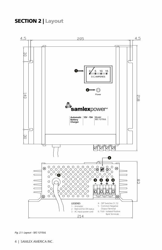
LEGEND:1 - Ammeter2 - Red LED for ON status3 - AC input power cord
4 - DIP Switches S1, S25 - Common Negative Output Terminal6, 7 & 8 - Isolated Positive Bank Terminals
Fig. 2.1: Layout - SEC-1215UL
4 | SAMLEX AMERICA INC. SAMLEX AMERICA INC. | 5
seCtIOn 2 | layout
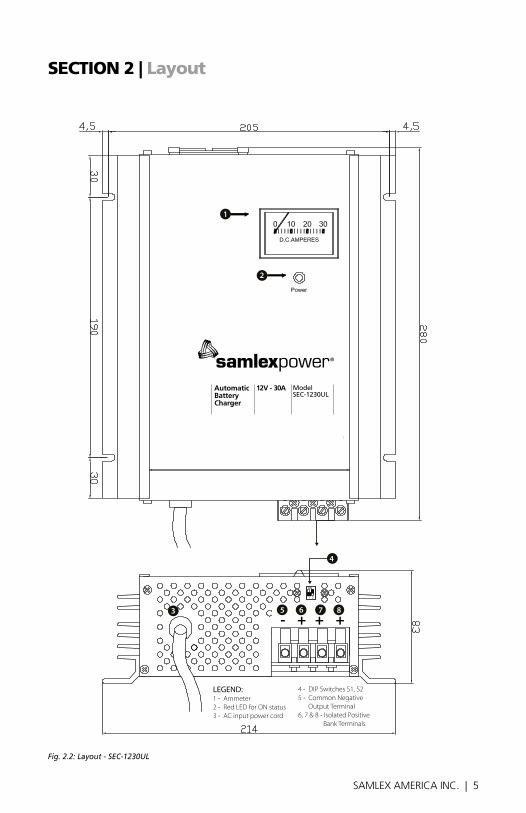
Fig. 2.2: Layout - SEC-1230UL
12V - 30AAutomaticBatteryCharger
ModelSEC-1230UL
LEGEND:1 - Ammeter2 - Red LED for ON status3 - AC input power cord
4 - DIP Switches S1, S25 - Common Negative Output Terminal6, 7 & 8 - Isolated Positive Bank Terminals
2
1
4
3 8765- + + +
6 | SAMLEX AMERICA INC.
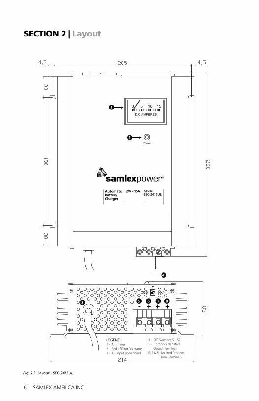
Fig. 2.3: Layout - SEC-2415UL
24V - 15AAutomaticBatteryCharger
ModelSEC-2415UL
8765- + + +
2
1
4
3
LEGEND:1 - Ammeter2 - Red LED for ON status3 - AC input power cord
4 - DIP Switches S1, S25 - Common Negative Output Terminal6, 7 & 8 - Isolated Positive Bank Terminals
seCtIOn 2 | layout
6 | SAMLEX AMERICA INC. SAMLEX AMERICA INC. | 7
seCtIOn 3 | Description, Features & Cooling
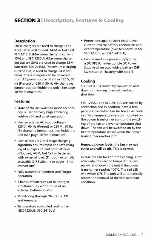
DescriptionThesechargersareusedtochargeLeadAcidBatteries(Flooded,AGMorGelCell).SEC-1215UL(Maximumchargingcurrent15A)andSEC-1230UL(Maximumcharg-ingcurrent30A)areusedtocharge12Vbatteries.SEC-2415UL(Maximumchargingcurrent15A)isusedtocharge24Vbat-teries.ThesechargerscanbepoweredfromACpowersourceofeither120V,60Hz(Pre-set)or230V,50Hz(Bychangingjumper position inside the unit - See page 10forinstructions).
Features
• Stateoftheartswitchedmodetechnol-ogyisusedforveryhighefficiency,lightweightandquietoperation.
• UserselectableACinputvoltage- 120V,60Hz(Pre-set)or230V,50Hz (by changing jumper position inside the unit(Seepage10forinstructions).
• Userselectable2or3stagechargingalgorithmensuresrapidandsafecharg-ingofalltypesofleadacidbatteries-Flooded,AGM,GelCellorbatterieswithexternalload.(ThroughexternallyaccessibleDIPSwitch-seepages11forinstructions)
• Fullyautomatic"ConnectandForget"operation
• 3banksofbatteriescanbechargedsimultaneouslywithoutuseofan externalbatteryisolator
• MonitoringthroughONstatusLED andAmmeter
• Temperaturecontrolledcoolingfan(SEC-1230UL,SEC-2415UL)
• Protectionsagainstshortcircuit,overcurrent,reversebatteryconnectionandovertemperature(overtemperatureforSEC-1230ULandSEC-2415UL)
• CanbeusedasapowersupplyorasaDCUPS(UninterruptibleDCPowerSupply)whenusedwithabattery(DIPSwitchsetat"Batterywithload")
coolingSEC-1215ULiscooledbyconvectionanddoesnothaveanythermaloverload shutdown.
SeC-1230UL and SeC-2415UL are cooled by convectionandinaddition,haveatem-peraturecontrolledfanforforcedaircool-ing.Twotemperaturesensorsmountedonthepowertransformercontroltheswitch-ingofthefanandovertemperatureshutdown.Thefanwillbeswitchedonbythefirsttemperaturesensorwhenthepowertransformerreaches70°C.
Hence, at lower loads, the fan may not cut in and will be off. this is normal.
Incasethefanfailsorifthecoolingisnotadequate,thesecondtemperaturesen-sorwillshutdowntheunitifthepowertransformerreaches100°C.TheredLEDwillswitchoff.Theunitwillautomaticallyrecoveronremovalofthermaloverloadcondition.
8 | SAMLEX AMERICA INC.
seCtIOn 4 | Charging states & Protections
Thesechargerscanbemanuallyselectedto operate in 3 stage or 2 stage modes (Pleasesee"Selecting the type of Battery and charging Stages"atpage11).Thechargingstagesaredescribedbelow:
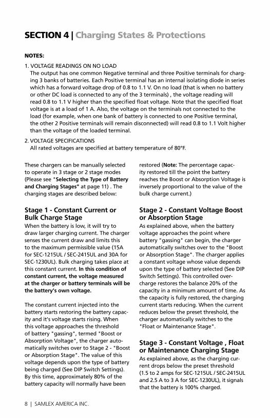
Stage 1 - constant current or Bulk charge StageWhenthebatteryislow,itwilltrytodrawlargerchargingcurrent.Thechargersensesthecurrentdrawandlimitsthistothemaximumpermissiblevalue(15AforSEC-1215UL/SEC-2415ULand30AforSEC-1230UL).Bulkchargingtakesplaceatthisconstantcurrent.in this condition of constant current, the voltage measured at the charger or battery terminals will be the battery's own voltage.
Theconstantcurrentinjectedintothebattery starts restoring the battery capac-ityandit'svoltagestartsrising.Whenthisvoltageapproachesthethresholdofbattery"gassing",termed"BoostorAbsorptionVoltage",thechargerauto-maticallyswitchesovertoStage2-"BoostorAbsorptionStage".Thevalueofthisvoltagedependsuponthetypeofbatterybeingcharged(SeeDIPSwitchSettings).Bythistime,approximately80%ofthebatterycapacitywillnormallyhavebeen
restored (note:Thepercentagecapac-ity restored till the point the battery reachestheBoostorAbsorptionVoltageisinverselyproportionaltothevalueofthebulkchargecurrent.)
Stage 2 - constant Voltage Boost or Absorption StageAsexplainedabove,whenthebatteryvoltageapproachesthepointwherebattery"gassing"canbegin,thechargerautomaticallyswitchesovertothe"BoostorAbsorptionStage".Thechargerappliesaconstantvoltagewhosevaluedependsuponthetypeofbatteryselected(SeeDIPSwitchSettings).Thiscontrolledover-chargerestoresthebalance20%ofthecapacityinaminimumamountoftime.Asthecapacityisfullyrestored,thechargingcurrentstartsreducing.Whenthecurrentreducesbelowthepresetthreshold,thechargerautomaticallyswitchestothe"FloatorMaintenanceStage".
Stage 3 - constant Voltage , Float or Maintenance charging StageAsexplainedabove,asthechargingcur-rentdropsbelowthepresetthreshold (1.5to2ampsforSEC-1215UL/SEC-2415ULand2.5Ato3AforSEC-1230UL),itsignalsthatthebatteryis100%charged.
nOtes:
1.VOLTAGEREADINGSONNOLOAD TheoutputhasonecommonNegativeterminalandthreePositiveterminalsforcharg-ing3banksofbatteries.EachPositiveterminalhasaninternalisolatingdiodeinserieswhichhasaforwardvoltagedropof0.8to1.1V.Onnoload(thatiswhennobatteryorotherDCloadisconnectedtoanyofthe3terminals),thevoltagereadingwillread0.8to1.1Vhigherthanthespecifiedfloatvoltage.Notethatthespecifiedfloatvoltageisataloadof1A.Also,thevoltageontheterminalsnotconnectedtotheload(forexample,whenonebankofbatteryisconnectedtoonePositiveterminal,theother2Positiveterminalswillremaindisconnected)willread0.8to1.1Volthigherthanthevoltageoftheloadedterminal.
2.VOLTAGESPECIFICATIONS Allratedvoltagesarespecifiedatbatterytemperatureof80°F.
8 | SAMLEX AMERICA INC. SAMLEX AMERICA INC. | 9
seCtIOn 4 | Charging states & Protections
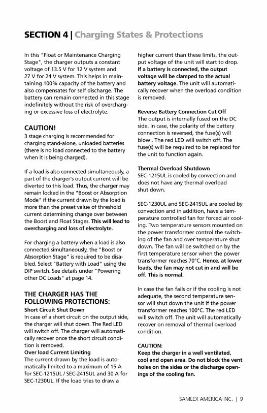
Inthis"FloatorMaintenanceChargingStage",thechargeroutputsaconstantvoltageof13.5Vfor12Vsystemand 27Vfor24Vsystem.Thishelpsinmain-taining100%capacityofthebatteryandalsocompensatesforselfdischarge.Thebattery can remain connected in this stage indefinitelywithouttheriskofovercharg-ingorexcessivelossofelectrolyte.
cAUtion!3stagechargingisrecommendedforchargingstand-alone,unloadedbatteries(there is no load connected to the battery whenitisbeingcharged).
Ifaloadisalsoconnectedsimultaneously,apartofthecharger'soutputcurrentwillbedivertedtothisload.Thus,thechargermayremainlockedinthe"BoostorAbsorptionMode"ifthecurrentdrawnbytheloadismorethanthepresetvalueofthresholdcurrentdeterminingchangeoverbetweentheBoostandFloatStages.this will lead to overcharging and loss of electrolyte.
Forchargingabatterywhenaloadisalsoconnectedsimultaneously,the"BoostorAbsorptionStage"isrequiredtobedisa-bled.Select"BatterywithLoad"usingtheDIPswitch.Seedetailsunder"PoweringotherDCLoads"atpage14.
tHe cHARgeR HAS tHe Following PRotectionS:Short circuit Shut DownIncaseofashortcircuitontheoutputside,thechargerwillshutdown.TheRedLEDwillswitchoff.Thechargerwillautomati-callyrecoveroncetheshortcircuitcondi-tionisremoved.over load current limitingThecurrentdrawnbytheloadisauto-maticallylimitedtoamaximumof15AforSEC-1215UL/SEC-2415ULand30AforSEC-1230UL.Iftheloadtriestodrawa
highercurrentthantheselimits,theout-putvoltageoftheunitwillstarttodrop.if a battery is connected, the output voltage will be clamped to the actual battery voltage. Theunitwillautomati-callyrecoverwhentheoverloadconditionisremoved.
Reverse Battery connection cut offTheoutputisinternallyfusedontheDCside.Incase,thepolarityofthebatteryconnectionisreversed,thefuse(s)willblow.TheredLEDwillswitchoff.Thefuse(s)willberequiredtobereplacedfortheunittofunctionagain.
thermal overload ShutdownSEC-1215ULiscooledbyconvectionanddoesnothaveanythermaloverload shutdown.
SeC-1230UL and SeC-2415UL are cooled by convectionandinaddition,haveatem-peraturecontrolledfanforforcedaircool-ing.Twotemperaturesensorsmountedonthepowertransformercontroltheswitch-ingofthefanandovertemperatureshutdown.Thefanwillbeswitchedonbythefirsttemperaturesensorwhenthepowertransformerreaches70°C.Hence, at lower loads, the fan may not cut in and will be off. this is normal.
Incasethefanfailsorifthecoolingisnotadequate,thesecondtemperaturesen-sorwillshutdowntheunitifthepowertransformerreaches100°C.TheredLEDwillswitchoff.Theunitwillautomaticallyrecoveronremovalofthermaloverloadcondition.
cAUtion: Keep the charger in a well ventilated, cool and open area. Do not block the vent holes on the sides or the discharge open-ings of the cooling fan.
10 | SAMLEX AMERICA INC.
seCtIOn 5 | Installation & Charger Operation
inStAllAtion
location, Mounting & SafetyThechargerisrequiredtobeinstalledinasafe,wellventilatedanddrylocation.Pleaseseethedetailsgivenunder"Impor-tantSafetyInstructions"onpage3.
Withthehelpof4screws,mountthechargeronaverticalbulkheadwiththeoutputterminalsidefacingdown.
output connectorsAterminalblockwithtubular,screwdowntypeofterminalsisusedforoutputcon-nection.Thediameterofthetubularholesisasfollows:SEC-1215UL 0.14inchesSEC-2415UL/SEC-1230UL 0.19inches
wires for Battery connectionToavoidpolarityerrorsandpossibledamage,neverusewiresofonlyonecolor.Useredinsulatedwire(s)forPosi-tiveconnection(s)andblackforNegativeconnection(s)
RecommendedDCwiresizesaregivenbelow.ThelengthinfeetisthelengthofthepairofthePositiveandNegativeDCwiresfromthechargertothebattery/other DC load:
LengthofthepairofthePositive&Negativecables
SeC-1215UL SeC-2415UL SeC-1230UL
0 to 6 ft. AWG #10 AWG #8
6 to 10 ft. AWG #8 AWG #6
10 to 20 ft. AWG #6 AWG #4
termination of wire ends Wireendsforconnectiontothechargershouldbeterminatedwithpintypeoflugsprovided.
cAUtion!For firm connection when using stranded cable, crimp / solder "pin" style terminal on the charger end of the Dc wires used for connecting to the battery / other Dc loads.
cHARgeR oPeRAtionPreparing the charger for operation:Selecting Ac input voltageThechargerispre-settooperatefrominputACvoltageof120VAC,60Hz.TooperatethechargerfromACinputvoltageof230VAC,50Hz,changetheinternalsettingasfollows:
1. Removethe4screwsontheammetersideofthetopcover
2. Gentlyslidethetopcoveroutby2to3inches.(cAUtion! the top cover will be restrained from fully sliding out by the wires connecting the am-meter, leD and the fan)
3. Locatethejumperwirewithaquickfemaledisconnect.Inthepre-setcondition,itisconnectedtothemaleverticalpinmarked"115V".Pullthisfemaledisconnectupwardstodis-connectfromthe"115V"position.Connectthistothemaleverticalpinmarked"230V"
4. Replacethefusewiththefuserecom-mendedfor230VACoperation(Seefuseratingatpage17)
5. ReplacetheACplugofthepowercordwithasuitable3pingrounded

10 | SAMLEX AMERICA INC. SAMLEX AMERICA INC. | 11
SECTION 5 | Installation & Charger Operation
plug to mate with the 230 VAC out-let. Caution: the new plug should have 3 poles i.e. Line (L) , neutral(n) and Earth ground. Color code for the power cord conductors is: - Line (L) - Black - neutral (n) - White - Earth ground - Green
Preparing the Charger For operation: Selecting the type of Battery and Charging StagesThe Float Voltage and Boost Voltage (Also called Absorption or Overcharge Voltage) of different types of Lead Acid Batteries are different. Also, when a charger is used to charge a battery and simultaneously supply a load , the Boost Stage is required to be disabled to prevent overcharging of
the battery . A DIP Switch is provided on top of the output terminals for selecting the battery type and for disabling the Boost Stage when charging loaded batter-ies. The following selections can be made with the help of the DIP Switch. Caution! Do not change the DiP Switch setting when the charger is operating. al-ways change the DiP Switch setting when the charger is off , i.e. after disconnecting the charger from the aC input power. notE: the voltages are for a temperature of 80°F. Caution! Please ensure that the position no. 4 of the DiP switch (S1-on & S2-on) is nEVER selected.
DiP SWitCh SEttinGS: SEC-1215uL/SEC-1230uL
S1 S2 Float BoostBattery
typeCharging
Stages
OFF * ON * 13.5 V * 14.4 V * Flooded / AGM *
3 Stages (Stages 1, 2, 3)
ON OFF 13.5 V 14.0 V Gel Cell 3 Stages (Stages 1, 2, 3)
OFF OFF 13.5 V Disabled Battery with Load
2 Stages (Stages 1, 3)
ON ON Caution! Do not use this setting
* Factory pre-set in this position
DiP SWitCh SEttinGS - SEC-2415uL
S1 S2 Float Boost Battery
type Charging
Stages
OFF * ON * 27 V * 28.8 V * Flooded / AGM *
3 Stages (Stages 1, 2, 3)
ON OFF 27 V 28.0 V Gel Cell 3 Stages (Stages 1, 2, 3)
OFF OFF 27 V Disabled Battery with load
2 Stages (Stages 1, 3)
ON ON Caution! Do not use this setting
* Factory pre-set in this position
12 | SAMLEX AMERICA INC.
seCtIOn 5 | Installation & Charger Operation
connecting the Batteries or other Dc loadsTheoutputhasacommonNegative(-)terminaland3Positiveterminalsforchargingupto3independentbanksofbatteries.EachPositiveconnectorhasit'sowninternalisolatingdiodewhichworksasabatteryisolator.Ifmorethanonebankofbatteriesisconnected,thesewillbecharged at the same time as long as the ACpowerisavailabletothecharger(themaximumchargingcurrentof15Aof SEC-1215UL/SEC-2415ULand30AofSEC-1230ULwillbesharedamongtheconnectedbanksofthebatteriesdepend-ingupontheirdischargedstates).IncasetheACpowerfailsorifthereisnooutputfromthecharger,theisolatingdiodeswillpreventcharging/dischargingamongthebatteriesconnectedtothebanks.
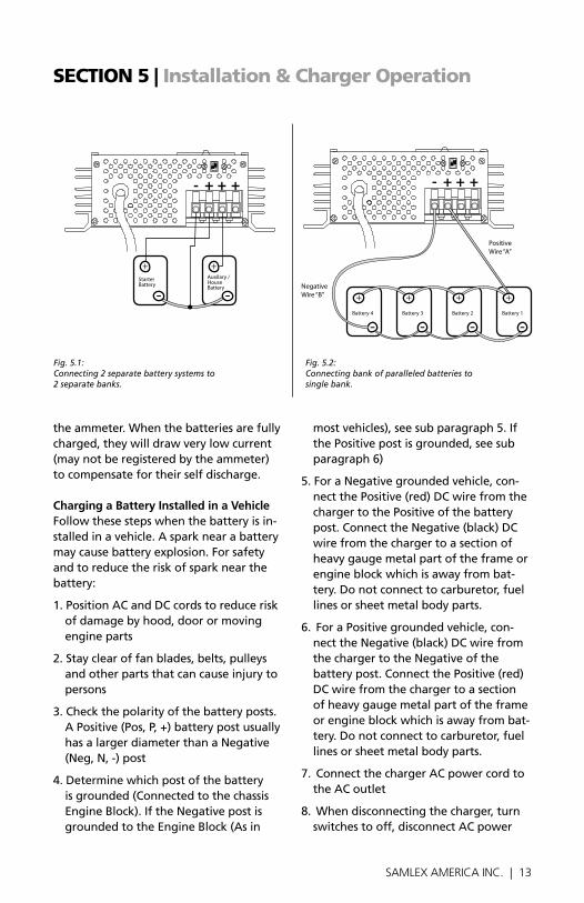
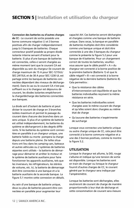
Theabovearrangementworksasabatteryisolatorandcandividethechargingcur-rentintoamaximumof3isolatedbranchesandallowscurrentflowineachbranchinonedirectiononly.Ifmorethanonebat-terysystemsarebeingusedindependently,thesystembatterieswilldischargetodifferentlevels.Ifsystembatteriesarecon-nectedinparalleltochargefromasinglecharger,aweakoradeadbatterywilldrainthechargefromthestrongbattery.SuchsituationoccursinRVs,boatsandothervehicleswhere2separatebatterysystemsareused–starterbatteryforstartingandrunningtheengineandtheotherauxiliary/housebatterysystemforrunningauxiliarydeviceslikeinverters,refrigerators,carstereosetc.Here,thestarterbatteryshouldbeconnectedtoonebankandtheauxiliary/housebatterytothesecondbank.Fig.5.1showsthisconnection.
Inasinglebatterybank,twoormorebatteries may be connected in parallel to
increasetheirAHcapacity.Thesewillbedischarged and charged as a single battery bank.Inthiscase,theparalleledbankofmultiple batteries is to be considered as asinglebankandconnectedtoanyoneofthe3banksofthechargerasshowninFig.5.2forbankof4batteries.Forproperchargingofallthebatteries,pleaseensurethatthePositivewire“A”fromthechargerisconnectedtothePositiveterminalofthefirstbattery(Battery1)andtheNegativewire“B”isconnectedtotheNegativeterminalofthelastbattery(Battery4).Thiswillensurethefollowing:
• Resistanceoftheinterconnectingcableswillbebalancedandtheindividualbat-terieswillseethesameseriesresistance
• Alltheindividualbatterieswillbecharged at the same charging current andthuswillbechargedtothesamestateofcharge
• Noneofthebatterieswillseeanover-charge condition
WhenconnectingasinglebatteryorothersingleDCload,itcanbeconnectedtothecommonNegativeandanyoneofthe3PositiveterminalsasinFig.5.2.
oPeRAtionWhenthechargerisswitchedon,the red LeD lights up indicating that output voltageisavailable.Whenthebatteriesarebeingchargedorwhenthecharger issupplyingotherDCload,thecurrent fedbythechargerwillbeindicatedby theammeter.
Whenthebatteriesaredischarged,theywilldrawchargingcurrentproportionalto their discharged condition (up to a maximumcurrentratingofthecharger)andthiscurrentdrawwillbeshownby
12 | SAMLEX AMERICA INC. SAMLEX AMERICA INC. | 13
theammeter.Whenthebatteriesarefullycharged,theywilldrawverylowcurrent (maynotberegisteredbytheammeter)tocompensatefortheirselfdischarge.
charging a Battery installed in a VehicleFollowthesestepswhenthebatteryisin-stalledinavehicle.Asparknearabatterymaycausebatteryexplosion.Forsafetyandtoreducetheriskofsparknearthebattery:
1.PositionACandDCcordstoreduceriskofdamagebyhood,doorormovingengine parts
2.Stayclearoffanblades,belts,pulleysand other parts that can cause injury to persons
3.Checkthepolarityofthebatteryposts.APositive(Pos,P,+)batterypostusuallyhasalargerdiameterthanaNegative(Neg,N,-)post
4.Determinewhichpostofthebatteryis grounded (Connected to the chassis EngineBlock).IftheNegativepostisgroundedtotheEngineBlock(Asin
mostvehicles),seesubparagraph5.IfthePositivepostisgrounded,seesubparagraph6)
5.ForaNegativegroundedvehicle,con-nectthePositive(red)DCwirefromthechargertothePositiveofthebatterypost.ConnecttheNegative(black)DCwirefromthechargertoasectionofheavygaugemetalpartoftheframeorengineblockwhichisawayfrombat-tery.Donotconnecttocarburetor,fuellinesorsheetmetalbodyparts.
6.ForaPositivegroundedvehicle,con-necttheNegative(black)DCwirefromthechargertotheNegativeofthebatterypost.ConnectthePositive(red)DCwirefromthechargertoasectionofheavygaugemetalpartoftheframeorengineblockwhichisawayfrombat-tery.Donotconnecttocarburetor,fuellinesorsheetmetalbodyparts.
7.ConnectthechargerACpowercordtotheACoutlet
8.Whendisconnectingthecharger,turnswitchestooff,disconnectACpower
seCtIOn 5 | Installation & Charger Operation
StarterBattery
Auxilary /HouseBattery
- + + +
Battery 4 Battery 3 Battery 2 Battery 1
Negative Wire “B”
Positive Wire “A”
- + + +
Fig. 5.1: Connecting 2 separate battery systems to 2 separate banks.
Fig. 5.2: Connecting bank of paralleled batteries to single bank.
14 | SAMLEX AMERICA INC.
seCtIOn 5 | Installation & Charger Operation
cord,removeconnectionfromthevehi-clechassisandthenremoveconnectionfromthebatteryterminal
charging a Battery outside the VehicleFollowthesestepswhenthebatteryisoutsidethevehicle.Asparknearthebatterymaycausebatteryexplosion.Forsafetyandtoreduceriskofsparknearthebattery,connectthechargerasfollows:
1.Checkthepolarityofthebatteryposts.APositive(Pos,P,+)batterypostusuallyhasalargerdiameterthanaNegative(Neg,N,-)post
2.Attachapieceofatleast3"ofAWG#6insulatedbatterywiretotheNegativebattery post
3.ConnectthePositive(red)DCwirefromthechargertothePositivebatterypost
4.PositionyourselfandthefreeendofthepieceofwireattachedtotheNega-tivepostasfarawayfromthebatteryaspossibleandthenconnecttheNegative(black)DCwirefromthechargertothefreeendofthepieceofwireattachedtotheNegativebatterypost
5.Donotfacethebatterywhenmakingthe final connection
6.ConnectthechargerACpowercord totheACoutlet
7.Whendisconnectingthecharger, alwaysdosoinreversesequenceof connectingprocedureandbreakthefirstconnectionwhilestandingasfarawayfromthebatteryaspractical
cHARging MoRe tHAn one BAnK oF BAtteRieScAUtion! when charging more than one bank of batteries at the same time using 3 Stage charging, ensure that the batteries in the banks are in a similar discharged condition. if one bank is completely discharged and another is almost fully charged, the bank that is fully charged will be subjected to over charge condition during the time when the charger remains in Boost Stage for charging the completely discharged bank. if batteries are in dis-similar states of charge, select DiP Switch setting for "Battery with load."
Powering other Dc loadsThechargercanbeusedasapowersup-plyorasaDCUPS.Forboththeseapplica-tions,firstsettheDIPSwitchto"Batterywithload".(See under " Selecting the type of Battery and charging Stages" on page 11).
Touseasapowersupply,firstswitchofftheDCload.ConnecttheDCloadbetweenthecommonNegativeterminalandoneofthethreePositiveterminals.ensure that the maximum current drawn by the Dc load is below the maximum current rating of the charger. Switch on the charger and then the Dc load.
InaDCUPS(Un-interruptiblePowerSup-ply),thechargersimultaneouslypowerstheDCloadaswellasthebattery.AslongastheACpowertothechargerisavail-ableandthechargerisworkingnormally,thechargerwillsupplytheDCloadaswellascharge/floatthebattery.IncasetheACpowerfailsorifthechargerstopswork-
14 | SAMLEX AMERICA INC. SAMLEX AMERICA INC. | 15
seCtIOn 5 | Installation & Charger Operation
ing,thebatterywillautomaticallypowertheDCload.AssoonastheACpowertothechargerisrestored,theDCloadwillonceagainbefedbythechargerandatthesametimethebatterywillberecharged.
cAUtion! Please ensure that the sum of the current drawn by the Dc load and the current desired for charging the battery is less than the maximum current capacity of the charger.
TouseasaDCUPS,firstswitchoffthe DCloadandconnectittothebattery.Nowconnectthebatteryasexplainedaboveunder"ChargingaBatteryoutsidetheVehicle"onpage14.SwitchonthechargerandthenswitchontheDCload.
seCtIOn 6 | troubleshooting
SYMPtoMS: cHARgeR PoweReD AnD connecteD to tHe BAtteRYthe Red leD is oFFTheDCsidefusemayhaveblownduetowrongpolarityofbatteryconnection. EnsurePositiveofthebatteryisconnectedtothePositiveofthechargerandtheNegativeofthebatteryisconnectedtotheNegativeofthecharger.Checkthefusesinsidethechargerandreplace,ifblown.
Thebatterymaybeshorted.Inthiscondi-tion,theunitisshutdownbytheshortcircuitprotectioncircuit.Removethebatteryconnection.IftheredLEDnowcomeson,thebatteryisshorted.IftheredLEDstilldoesnotcomeon,checkifthereisACpowerinthereceptacle.Ifthereispower,checktheACsidefuseinsidetheunit.Ifthefuseisnotblown,callTechnicalSupport.
the Red leD is on but the Ammeter Shows no ReadingThebatteryisfullycharged.Ifthebatteryisnotfullycharged,theconnectiontothe
batterymaybelooseoropen.Checktightnessandcontinuityofthebatteryconnection.
the Battery is getting over charged or BoilsThechargerisalsofeedingotherDCload(s)inparallelwiththebattery.TheDIPSwitchisnotselectedfor"BatterywithLoad".ChangeDIPSwitchsettingto"BatterywithLoad"(seeunder"PoweringotherDCloads"onpage14.
SYMPtoMS: cHARgeR PoweReD & DiSconnecteD FRoM BAtteRYthe Red leD is oFFCheckthereisACpowerinthereceptacle.Ifthereispower,checktheACsidefuseinsidetheunit.Ifthefuseisnotblown,checktheDCsidefuse.IftheDCsidefuseisnotblown,theoutputmaybeshorted.Inthiscondition,thechargerisshutdownbytheshortcircuitprotectioncircuit.Checkthattheoutputterminalsarenotshorted.Iftheterminalsarenotshorted,callTechnicalSupport.

16 | SAMLEX AMERICA INC.
seCtIOn 6 | troubleshooting
Ac Side Fuse Blows As Soon As Power is turned onTheACinputisselectedfor120VACbuttheunitispluggedinto230VAC.Alwayscheckthatthechargerissetforthecor-rectACmainsvoltage.IftheACinputvoltageiscorrect,thechargerisdefective.CallTechnicalSupport.
Dc Side Fuse Blows As Soon As the Battery is connectedWrongpolarityofthebatteryconnection.EnsurePositiveofthebatteryisconnectedtothePositiveofthechargerandtheNegativeofthebatteryisconnectedtotheNegativeofthecharger.
SYMPtoMS wHen tHe cHARgeR iS PoweReD AnD iS Being USeD AS A Dc PoweR SUPPlY/UPSthe Voltage Drops when load is Switched onTheloadistryingtodrawcurrentmorethanthecurrentlimitvalueofthecharger(thecurrentlimitvalueisthemaximum
specifiedchargingAmps).Oncetheloadcurrentreachesthecurrentlimitvalue,thecurrentlimitcircuitisactivatedandtheoutputvoltagedrops.Someloadslikemotors,compressors,incandescentlamps,halogenlamps,heatingelements,relays,coils,capacitorsetc.drawverylargeinrush/startingcurrentswhichmayreachup to 10 times their normal operating currents.Ensurethatthestarting/inrushcurrentorthemaximumoperatingcur-rentoftheloadislowerthanthecurrentlimitvalueofthecharger.
16 | SAMLEX AMERICA INC. SAMLEX AMERICA INC. | 17
seCtIOn 7 | Internal Fuse ratings & specifications
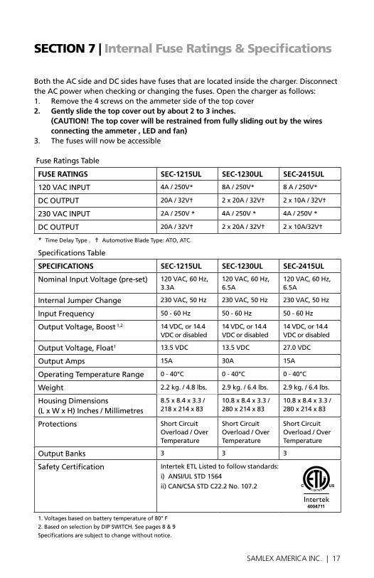
BoththeACsideandDCsideshavefusesthatarelocatedinsidethecharger.DisconnecttheACpowerwhencheckingorchangingthefuses.Openthechargerasfollows:1. Removethe4screwsontheammetersideofthetopcover2. gently slide the top cover out by about 2 to 3 inches.
(cAUtion! the top cover will be restrained from fully sliding out by the wires connecting the ammeter , leD and fan)
3. Thefuseswillnowbeaccessible
FuseRatingsTable
FUSe RAtingS Sec-1215Ul Sec-1230Ul Sec-2415Ul
120VACINPUT 4A/250V* 8A/250V* 8A/250V*
DCOUTPUT 20A/32V† 2x20A/32V† 2x10A/32V†
230VACINPUT 2A/250V* 4A/250V* 4A/250V*
DCOUTPUT 20A/32V† 2x20A/32V† 2x10A/32V†
* TimeDelayType.†AutomotiveBladeType:ATO,ATC.
SpecificationsTable
SPeciFicAtionS Sec-1215Ul Sec-1230Ul Sec-2415Ul
NominalInputVoltage(pre-set) 120VAC,60Hz,3.3A
120VAC,60Hz,6.5A
120VAC,60Hz,6.5A
InternalJumperChange 230VAC,50Hz 230VAC,50Hz 230VAC,50Hz
InputFrequency 50-60Hz 50-60Hz 50-60Hz
OutputVoltage,Boost1,2 14VDC,or14.4VDCordisabled
14VDC,or14.4VDCordisabled
14VDC,or14.4VDCordisabled
OutputVoltage,Float1 13.5VDC 13.5VDC 27.0VDC
OutputAmps 15A 30A 15A
OperatingTemperatureRange 0-40°C 0-40°C 0-40°C
Weight 2.2kg./4.8lbs. 2.9kg./6.4lbs. 2.9kg./6.4lbs.
HousingDimensions(LxWxH)Inches/Millimetres
8.5x8.4x3.3/218x214x83
10.8x8.4x3.3/280x214x83
10.8x8.4x3.3/280x214x83
Protections Short Circuit Overload/OverTemperature
Short Circuit Overload/OverTemperature
Short Circuit Overload/OverTemperature
OutputBanks 3 3 3
SafetyCertification IntertekETLListedtofollowstandards:
i)ANSI/ULSTD1564
ii)CAN/CSASTDC22.2No.107.2
1.Voltagesbasedonbatterytemperatureof80°F
2.BasedonselectionbyDIPSWITCH.Seepages8&9
Specificationsaresubjecttochangewithoutnotice.
4004711
18 | SAMLEX AMERICA INC.
seCtIOn 8 | warranty
2 YeAR liMiteD wARRAntY
SeC-1215UL / SeC-1230UL and SeC-2415UL manufacturedbySamlexAmerica,Inc.(the“Warrantor“)iswarrantedtobefreefromdefectsinwork-manshipandmaterialsundernormaluseandservice.Thewarrantyperiodis2yearsfortheUnitedStatesandCanada,andisineffectfromthedateofpurchasebytheuser(the“Purchaser“).
• WarrantyoutsideoftheUnitedStatesandCanadaislimitedto6months.Forawarrantyclaim,thePurchasershouldcontacttheplaceofpurchasetoobtainaReturnAuthorizationNumber.
• ThedefectivepartorunitshouldbereturnedatthePurchaser’sexpensetotheauthorizedlocation.Awrittenstatementdescribingthenatureofthedefect,thedateofpurchase,theplaceofpurchase,andthePurchas-er’sname,addressandtelephonenumbershouldalsobeincluded.
• IfupontheWarrantor’sexamination,thedefectprovestobetheresultofdefectivematerialorworkmanship,theequipmentwillberepairedorreplacedattheWarrantor’soptionwithoutcharge,andreturnedtothePurchaserattheWarrantor’sexpense.(ContiguousUSandCanadaonly)
• NorefundofthepurchasepricewillbegrantedtothePurchaser,unlesstheWarrantorisunabletoremedythedefectafterhavingareasonablenumberofopportunitiestodoso.WarrantyserviceshallbeperformedonlybytheWarrantor.AnyattempttoremedythedefectbyanyoneotherthantheWarrantorshallrenderthiswarrantyvoid.Thereshallbenowarrantyfordefectsordamagescausedbyfaultyinstallationorhook-up,abuseormisuseoftheequipmentincludingexposuretoexcessiveheat,saltorfreshwaterspray,orwaterimmersion.
• Nootherexpresswarrantyisherebygivenandtherearenowarrantieswhichextendbeyondthosedescribedherein.Thiswarrantyisexpressly inlieuofanyotherexpressedorimpliedwarranties,includinganyimpliedwarrantyofmerchantability,fitnessfortheordinarypurposesforwhichsuchgoodsareused,orfitnessforaparticularpurpose,oranyotherobli-gationsonthepartoftheWarrantororitsemployeesand representatives.
18 | SAMLEX AMERICA INC. SAMLEX AMERICA INC. | 19
seCtIOn 8 | warranty
• ThereshallbenoresponsibilityorliabilitywhatsoeveronthepartoftheWarrantororitsemployeesandrepresentativesforinjurytoanypersons,ordamagetopersonorpersons,ordamagetoproperty,orlossofincomeorprofit,oranyotherconsequentialorresultingdamagewhichmaybeclaimedtohavebeenincurredthroughtheuseorsaleoftheequipment,includinganypossiblefailureofmalfunctionoftheequipment,orpartthereof.TheWarrantorassumesnoliabilityforincidentalorconsequen-tialdamagesofanykind.
Samlex America inc. (the “warrantor”)www.samlexamerica.com

Contact Information
Toll Free NumbersPh: 1 800 561 5885
Fax: 1 888 814 5210
Local NumbersPh: 604 525 3836
Fax: 604 525 5221
Websitewww.samlexamerica.com
USA Shipping WarehouseKent WA
Canadian Shipping WarehouseDelta BC
Email purchase orders [email protected]
11001-SEC-1215-1230-2415UL-0513

Chargeur Commutateur, Automatique de Batterie Plomb-Acide
Guide d'utilisAtionVeuillez prendre con-naissance de ce guide AVANT toute utilisa-tion de votre chargeur de batterie
MODÈLES:SEC-1215ULSEC-1230ULSEC-2415UL
2 | SAMLEX AMERICA INC.
MAnuel d’utilisAtion: ChArGeurs de BAtterie | index
Section 1Mesures de sécurité ............................................................. 3
Section 2Présentation .......................................................................... 4
Section 3Description, Caractéristiques & Refroidissement .................. 7
Section 4Niveaux de charge et Protections ......................................... 8
Section 5Installation et Utilisation du chargeur ................................. 10
Section 6Résolution des problèmes .................................................. 15
Section 7Calibration des fusibles internes & Spécifications ............... 17
Section 8Garantie ......................................................................... 18
2 | SAMLEX AMERICA INC. SAMLEX AMERICA INC. | 3
seCtion 1 | Mesures de sécurité
De nombreux dangers peuvent se produire lorsque le chargeur n’est pas installé ou manipulé correctement. Veuillez lire les instructions suivantes afin d’éviter toutes blessures ou dom-mages personnels :
Risques liés à la batterie
• Afinderéduirelesrisquesd’explosion,suivezcesinstructionsetcellesapposéessur la batterie.
• Nejamaisfumerouapprocheruneflammeautourdelabatterieoudumoteur.
• Chargeruniquementdesbatteriesdetypeplomb-acide(inondées/AGM/cellulesgelées).Nepaschargerd’autrestypesdebatteriescommecelleennickel-cadmium.
• Nickel-hydruremétallique(Ni-MH),cellulessèches,etc.D’autrestypesdebatteriessontsusceptiblesd’imploseretpeuventprovo-querdesblessures.
• Nejamaischargerunebatteriegelée.
• Travailleràproximitédunebatterieplomb-acidepeutêtredangereux.Lesbatteriesgénèrentdesgazesexplosifsaucoursdeleurutilisation.Veuillezprendrelespré-cautionsnécessaireslorsdel’installationdevotrechargeuraproximitéd’unebatterieoud’uncompartimentdebatterie.(suivrelesinstructionsdesécuritéfourniesparlefabricantdelabatterie).
• Nejamaisdisposerlechargeurdirectementau dessus ou en dessous de la batterie étantchargée;lesgazesetfluidesdégagéspar la batterie entrainent la corrosion et l’altérationduchargeur.PlacerlechargeuraussiloinquelescâblesDCneleper-mettent.
Risques liés au chargeur
• N’utiliserenaucuncas,lechargeurdansunespaceconfinéoumalventilé.
• Installerlechargeurdansunendroitcor-rectementventilé,fraisetsec.
• Lechargeurnedoitpasêtreutilisédansunenvironnementhumide.Lorsqu’installésurunbateau,faitesattentionacequelechargeurnesoitpasexposéauxprojec-tionsd’eau.
• Nepasbloquerlesbouchesd’aérationetdeventilation.Prévoirundégagementd’aumoins15cm.
• Ilestrecommanded’installeretdebranch-erlechargeurparunélectriciencertifié.
• Uneinstallationdéfectueusesurunbateaupeutprovoquerlacorrosiondubateau.Ilestrecommandéquel’installationsoiteffectuéeparunélectriciencertifié.
• Déconnecterl’alimentationCAavantdemodifierlesréglagesdel’interrupteurDIP.
• Lechâssisduchargeurestconnectéalabrochedeterreducordond’alimentation.Assurez-vousquelabrochedeterreduboitierCAquialimentelechargeurestconnectéeausol.
• Nepasutiliserd’adaptateur.Siunboitieraprisedeterren’estpasdisponible,nepasutilisercechargeurjusqu'àcequ’unepriseadéquatenesoitinstalléeparunélectric-ienqualifié.
• Nepasutiliserlechargeursilecordond’alimentationestendommagé.
4 | SAMLEX AMERICA INC.
seCtion 2 | Présentation
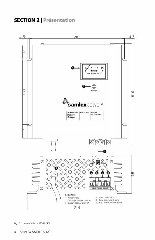
Fig. 2.1: presentation – SEC-1215UL
12V - 15AAutomaticBatteryCharger
ModelSEC-1215UL
4
3
8765- + + +
2
1
LEGEND:1 - Ammeter2 - Red LED for ON status3 - AC input power cord
4 - DIP Switches S1, S25 - Common Negative Output Terminal6, 7 & 8 - Isolated Positive Bank Terminals
LEGENDE:1 - Ampèremètre2 - DEL rouge lorsqu’en marche3 - Cordon d’alimentation CA
4 - Interrupteurs DIP S1, S25 - Borne commune de sortie 6,7 & 8 - Bornes positives isolées
4 | SAMLEX AMERICA INC. SAMLEX AMERICA INC. | 5
seCtion 2 | Présentation
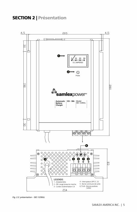
Fig. 2.2: présentation – SEC-1230UL
12V - 30AAutomaticBatteryCharger
ModelSEC-1230UL
LEGEND:1 - Ammeter2 - Red LED for ON status3 - AC input power cord
4 - DIP Switches S1, S25 - Common Negative Output Terminal6, 7 & 8 - Isolated Positive Bank Terminals
2
1
4
3 8765- + + +
LEGENDE:1 - Ampèremètre2 - DEL rouge lorsqu’en marche3 - Cordon d’alimentation CA
4 - Interrupteurs DIP S1, S25 - Borne commune de sortie 6,7 & 8 - Bornes positives isolées
6 | SAMLEX AMERICA INC.
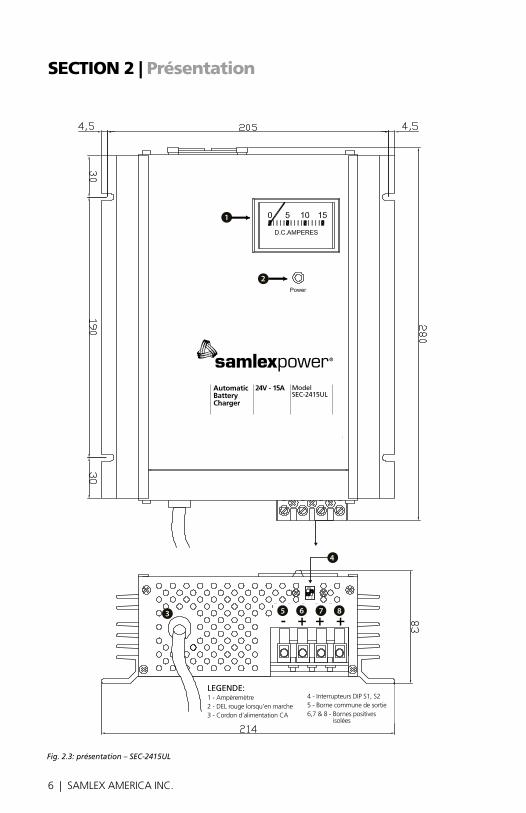
Fig. 2.3: présentation – SEC-2415UL
seCtion 2 | Présentation
24V - 15AAutomaticBatteryCharger
ModelSEC-2415UL
8765- + + +
2
1
4
3
LEGEND:1 - Ammeter2 - Red LED for ON status3 - AC input power cord
4 - DIP Switches S1, S25 - Common Negative Output Terminal6, 7 & 8 - Isolated Positive Bank Terminals
LEGENDE:1 - Ampèremètre2 - DEL rouge lorsqu’en marche3 - Cordon d’alimentation CA
4 - Interrupteurs DIP S1, S25 - Borne commune de sortie 6,7 & 8 - Bornes positives isolées
6 | SAMLEX AMERICA INC. SAMLEX AMERICA INC. | 7
seCtion 3 | description, Caractéristiques et refroidissement
DescriptionCeschargeurssontdestinésachargerdesbatteriesdetypeplomb-acide(inondées/AGM/cellulesgelées).
SEC-1215UL(courantdechargemaximum15A)etSEC-1230UL(courantdechargemaxi-mum30A)sontutiliséespourchargerdesbatteriesde24V.CeschargeurspeuventêtrealimentésdepuisunesourcedeCAde120V,60Hz(réglagepardéfaut)ou230V,50Hz(enchangeantlapositiondudisjoncteurauseindel’unité–voirinstructionsenpage10).
caractéristiques
• Latechnologieàdécoupagehautegammeestutiliséeenraisondesonimportanteefficacité,desonpoidslégeretdesonfonctionnementsilencieux.
• Latensiond’entréeduCAestsélectionna-bleparl’utilisateur–120V,60Hz(réglagepardéfaut)ou230V,50Hz(enchangeantlapositiondudisjoncteurauseindel’unité–voirinstructionsenpage10).
• L’utilisateurpeutsélectionner2ou3niveauxd’algorithmesdechargeetpro-céderalachargedetouteslesbatteriesdetypeplomb-acideentoutesécurité-inondées/AGM/cellulesgeléesoudesbatteriesachargexterne.(interrupteurDIPaccessibleenexterne–voirinstructionsenpage11).
• Fonctionnemententièrementautomatique«Chargezetoubliez».
• 3banquesdebatteriespeuventêtrechargéessimultanémentsansavoiràuti-liserunisolateurexternedebatterie.
• Contrôleeffectueal’aidedelaDEL,indi-quantlestatutONetl’ampèremètre.
• Températureréguléeparventilateur.
• Protectionscontrelescourts-circuits,lasurcharge,laconnexioninverséedela
batterieetlasurchauffe(surchauffepourSEC-1230ULetSEC-2415UL)
• Peutêtreutilisécommesourced’énergieoucommeASICC,lorsqu’utiliséavecunebatterie(option«batterieaveccharge»sélectionnéal’aidedel’interrupteurDIP).
RefroidissementSEC-1215ULestrefroidieparconvectionetnepossèdepasdeprotecteurthermiquedesurcharge.
SEC-1230ULetSEC-2415ULsontrefroidisparconvectionetpossèdentégalementunventi-lateurrégulantetcontrôlantlatempératuredecharge.Deuxcapteursthermiquesmontessurletransformateurélectriquecontrôlentledéclenchementduventilateuretleprotec-teurthermiquedesurcharge.Leventilateurs’enclenchelorsquelepremiercapteurthermiqueindiquequeletransformateuratteintles70°C.
cependant, lors de charges minimes, le ventilateur peut ne pas se déclencher et être éteint. ceci est normal.
Danslecasouleventilateurnefonctionnepasouestinadéquat,lesecondcapteurther-miqueentraineral’arrêtdel’unitédesquelatempératuredutransformateuratteintles100°C.LaDELrougesemettraenpositionOFF.L’unitéseremettraenmarcheunefoisl’étatdesurchauffeterminé.
8 | SAMLEX AMERICA INC.
seCtion 4 | niveaux de charge et Protections
Ceschargeurspeuventêtresélectionnésmanuellementafindefonctionnerenniveau2ouniveau3.(Veuillezconsulter«Sélec-tionnerletypedebatterieetlesniveauxdecharge»enpage11).Lesniveauxdechargesontdécritsci-dessous:
niveau 1 – courant constant ou charge de masseLorsquelabatterieestdéchargée,elleatendanceàconsommerplusdecourantdecharge.Lechargeursentcetteconsommationdecourantetlalimiteaunevaleurpermis-siblemaximum(15ApourSEC-1215UL/SEC-2415ULet30ApourSEC-1230UL).Lachargedemassesefaitaucoursdececourantconstant. Dans ce cas de courant constant, la tension mesurée aux bornes de la batterie ou du chargeur sera la tension propre de la batterie.
Lecourantconstantinjectédanslabatterierestaurelescapacitésdelabatteriepeuapeuetsatensioncommenceaaugmenter.Lorsquelatensionapprocheleseuildegazéi-ficationdelabatterie,appelée«tensiond’amplificationoud’absorption».Lavaleurdecettetensiondépenddutypedebatteriechargée(voirRéglagesdel’interrupteurDIP).Désormais,80%descapacitésdelabatterieontnormalementétérestores(note:lepour-centagedecapacitérestauréejusqu’acequelabatterieatteignelatensiond’amplificationoud’absorptionestinversementproportionnellealavaleurducourantdechargedemasse.)
niveau 2 – Amplification courante de tension ou absorptionCommeexpliquéci-dessus,lorsquelatensiondelabatterieavoisinel’étatde«gazéifica-tion»,lechargeurpasseautomatiquementenphase«d’amplificationoud’absorption».Lechargeurappliqueunetensioncou-rantedontlesvaleursdépendentdutypedebatteriesélectionnée(voirRéglagesdel’interrupteurDIP).Cettesurchargecontrôléerestaureles20%restantdescapacitésdelabatteriedansunlapsdetempsminimum.Lorsquelescapacitéssontentièrementrestaurées,lecourantdechargecommenceàdiminuer.Lorsquelecourantdiminueetsetrouveendessousduseuilpréréglé,lechargeurpasseautomatiquementaunniveaudechargede«flottementoud’entretien».
niveau 3 – tension constante, charge de flottement ou d’entretien Commeexpliqueci-dessus,lorsquelecourantdechargechuteendessousduseuilprésélec-tionné(1,5a2ampèrespourSEC-1215UL/SEC-2415ULet2,5Aa3ApourSEC-1230UL),celaindiquequelabatterieestchargéea100%.
Aucoursdecettechargede«flottementoud’entretien»,lechargeurdélivreunetensionconstantede13,5Vpourunsystème12Vetunetensionde27Vpourunsystème24V.Celaaideàconserver100%descapacitésdelabatterieetcompenseégalementl’auto
notes:
1.LECTURESDETENSIONHORS-CHARGE L’alimentationdisposed’unebornecommunenégativeetdetroisbornespositivespourlecharge-mentdetroisbanquesdebatterie.Chaquebornepositivedisposed’unesériedediodesinternesisolantesquiàunechutedetensiondirectede0,8à1,1v.Horscharge,(cequisignifiequ’aucunebatterieouautreccestconnecteau3bornes),lalecturedetensionindiquera0,8à1,1vsupé-rieurealatensiondeflottementspécifiée.Notezquelatensiondeflottementspécifiéeestàunechargede1a.Aussi,latensiondesbornesnonconnectéesàlacharge(parexemple,lorsqu’unebanquedebatteriesestconnectéeaunebornepositive,les2autresbornespositivesdemeurerontdéconnectées)indiqueraunetensionde0,8à1,1vsupérieurealatensiondelaborneencharge.
2.SPECIFICATIONSSURLATENSION Touteslestensionsévaluéessontspécifiéesàunetempératuredebatteriede27°C.
8 | SAMLEX AMERICA INC. SAMLEX AMERICA INC. | 9
seCtion 4 | niveaux de charge et Protections
déchargement.Labatteriepeutdemeurerconnectéeàceniveauindéfinimentsansrisquerlasurchargeoulaperteexcessived’électrolytes.
Attention !Lachargeniveau3estrecommandéepourlespilesoupilesoubatteriesdéchargées(iln’yapasdechargeconnectéealabatterielorsqu’elleestencoursdechargement).
Siunechargeestégalementconnectéesimul-tanément,unepartieducourantdesortieduchargeurseradétournéverscettecharge.Cependant,lechargeurpeutresterbloqueenmode«d’amplificationoud’absorption),silecourantinjecteparlachargeestsupérieurealavaleurprésélec-tionnéeduseuildecourantdéterminantlechangemententrelesniveauxd’amplificationetdeflottement.cela entrainera a une sur-charge et a un perte d’électrolytes.
Pourchargerunebatterielorsquelachargeestconnectéesimultanément,ilestrequisdedésactiverleniveaude«flottementetd’absorption».Sélectionner«Batterieaveccharge»al’aidedel’interrupteurDIP.Con-sultezlesdétailsenpage14«Activerd’autreschargesCC».
Le cHARGeUR PoSSeDe LeS PRotectionS SUiVAnteS :Protection contre les courts-circuitsEncasdecourt-circuitducourantdesortie,lechargeurs’éteindra.LaDELrouges’éteindra.Lechargeurredémarreraautomatiquementunefoislecourt-circuitréparé.
Limitation de courant de surcharge - Lecourantgénéréparlachargeestautoma-tiquementlimitéàunetensionmaximumde15ApourSEC-1215UL/SEC-2415ULetde30ApourSEC-1230UL.Silachargetentedegénéreruncourantsupérieuràceslimites,latensiondesortiedel’unitécommenceraàchuter.
Siunebatterieestconnectée,latensiondesortieseraégaleàcelledelabatterieencharge.L’unitéredémarreraautomatique-mentlorsquel’étatdesurchargeseraachevé.
extinction de la connexion inversée de la batterie - Lecourantdesortieestéquipédefusiblesinternes.Aucasou,lapolaritédelaconnexiondelabatteriesoitinversée,lesfusiblesexploseront.
Protection anti-surchauffe - SEC-1215estrefroidieparconvectionetnepossèdepasdeprotectionanti-surchauffe.
SEC-1230ULetSEC-2415ULsontrefroidisparconvectionetpossèdentégalementunventilateurrégulantetcontrôlantlatempé-raturedecharge.Deuxcapteursthermiquesmontessurletransformateurélectriquecontrôlentledéclenchementduventilateuretleprotecteurthermiquedesurcharge.Leventilateurs’enclenchelorsquelepremiercapteurthermiqueindiquequeletransfor-mateuratteintles70°C.cependant, lors de charges minimes, le ventilateur peut ne pas se déclencher et être éteint. ceci est normal.
Danslecasouleventilateurnefonctionnepasouinadéquat,lesecondcapteurther-miqueentraineral’arrêtdel’unitédesquelatempératuredutransformateuratteintles100°C.LaDELrougesemettraenpositionOFF.L’unitéseremettraenmarcheunefoisl’étatdesurchauffeterminé.
Attention : conservez le chargeur dans un lieu frais et ventile. ne pas obstruer les trous d’aération sur les cotés ni les ouvertures du ventilateur.
10 | SAMLEX AMERICA INC.
seCtion 5 | installation et utilisation du chargeur
inStALLAtion
emplacement, montage et sécuritéLechargeurdoitêtreinstallédansunlieusur,secetcorrectementventilé.Veuillezcon-sulterlesdétailsconcernantles«Instructionsimportantesdesécurité»enpage3.
Al’aidede4visses,fixezlechargeursurunecloisonverticale,labornedesortiefaceausol.
connecteurs de sortieUnborniercomposédebornestubulairesestutilisépourlaconnexiondesortie.Lesdiamè-tresdestroustubulairessontlessuivants:
SEC-1215UL 0,14poucesSEC-2415UL/SEC-1230UL 0,19pouces
câbles pour la connexion de la batterie Pourévitertouteserreursdepolaritéetdesdommageséventuels,nejamaisutiliserdecâblesdemêmecouleur.Utilisezdescâblesdecouleurrougepourlesconnexionsàlabornepositiveetdescâblesdecouleurnoirepourlesconnexionsàlabornenégative.
LesdiamètresdecâblesdeCCrecommandéssontdécritsci-dessous.Lalongueurenmètrecorrespondalalongueurdescâblespositifsetnégatifsdepuislechargeurjusqu'àlabat-terie/autreschargesdeCC:
Longueurde la paire descâblespositif&négatif
SEC-1215ULSEC-2415UL SEC-1230UL
0 a 6 pieds AWG #10 AWG #8
6 a 10 pieds AWG #8 AWG #6
10 a 20 pieds AWG #6 AWG #4
terminaison des câbles Lesterminaisonsdescâblespourla connexionduchargeurdoiventêtreenformed’épingle.
Attention !Pour une connexion ferme lorsque vous utilisez un câble toronné, pincez / soudez la borne en forme « d’épingle » sur la termi-naison des câbles de cc du chargeur utilisés pour la connexion de la batterie / autres charges de cc.
UtiLiSAtion DU cHARGeURPréparation du chargeur pour utilisation :Sélection de la tension d’entrée de cALechargeurestprésélectionnéafind’êtreutilisédepuisunetensiond’entréedeCAde120VAC,60Hz.Afind’utiliserlechargeurdepuisunetensiond’entréedeCAde230VAC,50hz,veuillezprocéderauxréglagesinternessuivants:
1.Retirezles4vissesducouvercledel’ampèremètre
2. Faites glisser délicatement le couvercle de 5 à 8 cm. (Attention ! Le couvercle sera retenu par les câbles connectant l’ampèremètre, la DeL et le ventilateur)
3.Localisezlecâbledudisjoncteurparunecourtedéconnectionducâblefemelle.Lecâblefemelleestconnecteaucâblemâlemarque«115V»danslesréglagesdeprésélection.Tirezsurlecâblefemelleafindeledéconnecterdelaposition «115V».Connectez-leaucâblemaleverticalmarqué«230V».
4.Remplacezlefusibleaveclefusiblerecom-mandepourl’utilisationde230VAC(voircalibrationdesfusiblesenpage17)
5.Remplacezlecordond’alimentationdeCAavecunepriseCAdemiseaterrea3broches et branchez-la a une sortie de 230VAC.ATTENTION:lanouvelleprisedoitavoirtroispôles,c.a.d,Ligne(L),
10 | SAMLEX AMERICA INC. SAMLEX AMERICA INC. | 11
seCtion 5 | installation et utilisation du chargeur
Neutre(N)etMiseaterre.Lecodecouleurpourlecordond’alimentationest:
- Ligne(L)–Noir- Neutre(N)–Blanc- Miseaterre–Verte
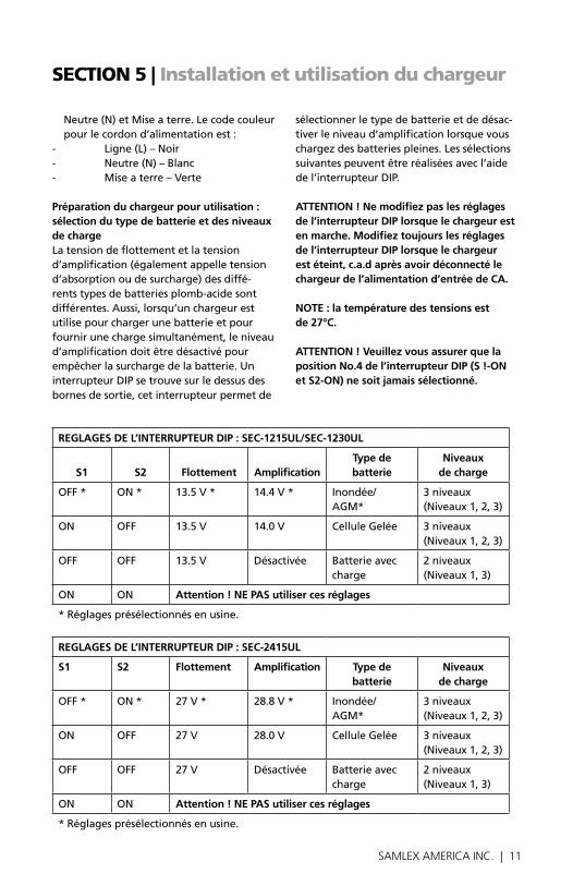
Préparation du chargeur pour utilisation : sélection du type de batterie et des niveaux de chargeLatensiondeflottementetlatensiond’amplification(égalementappelletensiond’absorptionoudesurcharge)desdiffé-rentstypesdebatteriesplomb-acidesontdifférentes.Aussi,lorsqu’unchargeurestutilise pour charger une batterie et pour fournirunechargesimultanément,leniveaud’amplificationdoitêtredésactivépourempêcherlasurchargedelabatterie.UninterrupteurDIPsetrouvesurledessusdesbornesdesortie,cetinterrupteurpermetde
sélectionnerletypedebatterieetdedésac-tiverleniveaud’amplificationlorsquevouschargezdesbatteriespleines.Lessélectionssuivantespeuventêtreréaliséesavecl’aidedel’interrupteurDIP. Attention ! ne modifiez pas les réglages de l’interrupteur DiP lorsque le chargeur est en marche. Modifiez toujours les réglages de l’interrupteur DiP lorsque le chargeur est éteint, c.a.d après avoir déconnecté le chargeur de l’alimentation d’entrée de cA. note : la température des tensions est de 27°c. Attention ! Veuillez vous assurer que la position no.4 de l’interrupteur DiP (S !-on et S2-on) ne soit jamais sélectionné.
ReGLAGeS De L’inteRRUPteUR DiP : Sec-1215UL/Sec-1230UL
S1 S2 Flottement Amplificationtype de batterie
niveaux de charge
OFF* ON* 13.5V* 14.4V* Inondée/AGM*
3niveaux(Niveaux1,2,3)
ON OFF 13.5V 14.0V CelluleGelée 3niveaux(Niveaux1,2,3)
OFF OFF 13.5V Désactivée Batterieaveccharge
2niveaux(Niveaux1,3)
ON ON Attention ! ne PAS utiliser ces réglages
*Réglagesprésélectionnésenusine.
ReGLAGeS De L’inteRRUPteUR DiP : Sec-2415UL
S1 S2 Flottement Amplification type de batterie
niveaux de charge
OFF* ON* 27V* 28.8V* Inondée/AGM*
3niveaux(Niveaux1,2,3)
ON OFF 27V 28.0V CelluleGelée 3niveaux(Niveaux1,2,3)
OFF OFF 27V Désactivée Batterieaveccharge
2niveaux(Niveaux1,3)
ON ON Attention ! ne PAS utiliser ces réglages
*Réglagesprésélectionnésenusine.
12 | SAMLEX AMERICA INC.
seCtion 5 | installation et utilisation du chargeur
connexion des batteries ou d’autres charges de cc - Lecourantdesortiepossèdeunebornecommunenégative(-)et3bornespositivesafindechargerindépendammentjusqu'à3banquesdebatteries.Chaqueconnecteurpositifpossèdesaproprediodeisolanteinterneservantd’isolantpourlabatterie.Siplusd’unebanquedebatteriesestconnectée,celles-ciserontchargéesaumêmemomenttantquelecourantCAestdisponibleauseinduchargeur(lecourantdechargemaximumde15ApourSEC-1215UL/SEC-2415ULetde30ApourSEC-1230ULestpartageentrelesbanquesdebatteriescon-nectéesdépendantdesniveauxdedécharge-ment).DanslecasoulecourantCAn’estpassuffisantousilechargeurestdépourvudecourant,lesdiodesisolantesempêcherontlacharge/déchargedesbatteriesconnectéesauxbanques.
Ladiodesertd’isolantdebatterieetpeutdiviserlecourantdechargeen3branchesisoléesmaximumetpermetlepassageducourant dans chacune des branches dans un sensunique.Siplusd’unsystèmedebatterieestutiliséindépendamment,lesbatteriesdusystèmesedéchargerontàdesdegrésdiffé-rents.Silesbatteriesdusystèmesontconnec-téesenparallèleàunchargeurunique,unebatteriefaibleoumortepomperalachargedepuisunebatteriepleine.Detellessitua-tionsontlieudanslescamping-cars,bateauxetautresvéhiculesou2systèmesdebatteriesséparéessontutilisés–labatteriededémar-ragepourdémarreretarrêterlemoteuretlesystèmedebatterieauxiliairepourfairefonctionnerlesappareilsauxiliaires,telsquelesinverseurs,lesréfrigérateurs,lesstéréosdevoitures,etc.Ici,labatteriededémarragedoitêtreconnectéeàunebanqueetalabatterieauxiliairedelasecondebanque.Lafigure5.1montrecetteconnexionendétails. Auseind’unebanquedebatterieunique,deuxouplusdebatteriespeuventêtrecon-nectéesenparallèlepouraugmenterleur
capacitéAH.Cesbatteriesserontdéchargéesetchargéescommeunebanquedebatterieunique.Danscecas,labanqueenparallèledebatteriesmultiplesdoitêtreconsidéréecommeunebanqueuniqueetdoitêtreconnectéeàunedes3banquesduchargeurcommeleprésentelafigure5.2pourunebanquede4batteries.Pourunchargementcorrectdetouteslesbatteries,veuillez-vousassurerquelecâblepositif«A»duchargeurestconnectéàlabornepositivedelapremièrebatterie(Batterie1)etquelecâblenégatif«B»estconnectéàlabornenégativedeladernièrebatterie(batterie4).Celapermettra:
• Quelarésistancedescâblesd’interconnexionsoitéquilibréeetquelesbatteriesindividuellesreçoiventlamêmerésistanceensérie.
• Quelesbatteriesindividuellessoientchargéesaveclemêmecourantdechargeetqu’ellessoientdoncchargéesaumêmeétatdecharge
• Qu’aucunedesbatteriesn’expérimente de surcharge
LorsquevousconnectezunebatterieuniqueouautrechargeuniquedeCC,celapeutêtreconnectéàlabornecommunenégativeetaunedes3bornespositives,commelemontrelafigure5.2.
UtiLiSAtionLorsquelechargeurestallume,laDELrouges’allumeetindiquequ’unetensiondesortieestdisponible.Lorsquelesbatteriessontentraindechargeroulorsquelechargeurfournitd’autreschargesdeCC,lecourantgénéréparlechargeurseraindiqueparl’ampèremètre.
Lorsquelesbatteriessontdéchargées,ellessoutirerontdecourantdechargedemanièreproportionnelleàleurétatdedéchargeetcetteconsommationdecourantseramesure
12 | SAMLEX AMERICA INC. SAMLEX AMERICA INC. | 13
parl’ampèremètre.Lorsquelesbatteriessontcomplètementchargées,ellesgénèrerontuntrèsfaiblecourant(quipeutnepasêtreenregistréparl’ampèremètre)afindecom-penserleurautodéchargement.
charger une batterie installe dans un véhiculeSuivezcesétapeslorsquelabatterieestinstalléeauseind’unvéhicule.Uneétincelleautourdelabatteriepeutprovoquerl’explosiondecelle-ci.Pourdesraisonsdesécuritéetpourréduirelerisqued’étincellesauxalentoursdelabatterie:
1.PositionnezlescâblesCAetCCafinderéduirelesrisquesdedommagescausésparlecapot,laportière,ouautrespiècesdumoteur.
2.Eloignez-vousdespalesduventilateur,descourroies,despouliesetautrespiècespouvantprovoquerdesblessures.
3.Vérifiezlapolaritédesbornesdelabat-terie.LaborneApositive(Pos,P,+)estgénéralementpluslargequelabornenégative(Neg,N,-).
4.Déterminezquellebornedelabatterieestmiseaterre(connectéeauchâssisdumoteur).Silabornenégativeestmiseà
terreaumoteur(commedanslaplupartdesvéhicules),veuillezlireleparagraphe5ci-dessous.Silabornepositiveestmiseaterre,veuillezlireleparagraphe6ci-dessous.
5.Pourunvéhiculedemiseàlaterrenéga-tive,connectezlecâbledeCCpositif(rouge)duchargeuràlabornepositivedelabatterie.ConnectezlecâbledeCCnégatif(noir)duchargeuràunepiècemé-talliquetrèsrésistantesituéesurlecadredumoteuretquisetientéloignéedelabatterie.Nepasconnecteraucarburateur,niauxtuyauxdecarburantouauxpiècesmétalliquesdelacarrosserie.
6.Pourunvéhiculedemiseàlaterrenéga-tive,connectezlecâbledeCCnégatif(noir)duchargeuràlabornepositivedelabatterie.ConnectezlecâbledeCCpositif(rouge)duchargeuràunepiècemétal-liquetrèsrésistantesituéesurlecadredumoteuretquisetientéloignéedelabatterie.Nepasconnecteraucarburateur,niauxtuyauxdecarburantouauxpiècesmétalliquesdelacarrosserie.
7.Connectezlecordond’alimentationCAduchargeuràuneprisesecteurCA.
seCtion 5 | installation et utilisation du chargeur
StarterBattery
Auxilary /HouseBattery
- + + +
Battery 4 Battery 3 Battery 2 Battery 1
Negative Wire “B”
Positive Wire “A”
- + + +
Fig. 5.1: Connexion de deux systèmes de batterie distincts à deux bancs de batterie indépendants.
Fig. 5.2: Connexion d'un banc de batteries en parallèle à un seul banc.
14 | SAMLEX AMERICA INC.
seCtion 5 | installation & Charger operation
8.Lorsquevousdéconnectezlechargeur,éteigneztouslesinterrupteurs,dé-branchezlecordond’alimentationdeCAetdébrancheztoutesconnexionsduchâssisduvéhicule,puisdébrancheztoutesconnexionsauxbornesdelabatterie.
charger une batterie hors d’un véhiculeSuivezcesétapeslorsquelabatterieesthorsduvéhicule.Uneétincelleàproximitédelabatteriepeutentrainerl’explosiondecelle-ci.Pourdesraisonsdesécuritéetpourréduirelesrisquesd’étincellesaproximitédelabat-terie,connectezlechargeurcommesuit:
1.Vérifiezlapolaritédesbornesdelabat-terie.LaborneApositive(Pos,P,+)estgénéralementpluslargequelabornenégative(Neg,N,-).
2.Attachezunepièced’aumoins7,5cmdecâbleisoledebatteried’AWG#6alabornenégativedelabatterie.
3.ConnectezlecâblepositifdeCC(rouge)duchargeur a l aborne positive de la batterie
4.Positionnez-vousainsiquelapartiedénu-déeducâbleattachealabornenégativeaussiloinquepossibledelabatterieetconnectezensuitelecâbledeCCnégatif(noir)duchargeuràlapartiedénudéeducâbleattachelabornenégativedelabat-terie.
5.Nejamaissemettrefacealabatterielor-squevousprocédezalaconnexionfinale.
6.Connectezlecordond’alimentationCAduchargeuràuneprisesecteurCA
7.Lorsquevousdéconnectezlechargeur,veuilleztoujoursprocédezdansl’ordreinversedecetteprocédureetdébranchezlapremièreconnexionenpremiertoutenrestantaussiloinquepossibledelabat-terie
cHARGeR PLUS D’Une BAnQUe De BAtteRieSATTENTION!Lorsquevouschargezplusd’unebanquedebatteriesenmêmetempsenutilisantleniveaudecharge3,assurez-0vousquelesbatteriesdanslesbanquessonttoutesdéchargéesaumêmeniveau.Siunebanqueestcomplètementdéchargéeetuneautrepresqueentièrementchargée,labanquequiestcomplètementchargéeserasujetteaunesurchargetantquelechargeurestenphased’amplificationpourchargerlabanquecomplètementdéchargée.Silesbatteriessontàdesdifférentsniveauxdedéchargement,sélectionnezl’option«Bat-terieaveccharge»àl’aidedel’interrupteurDIP.
charger d’autres charges de ccLechargeurpeutêtreutilisécommesourcedecourantoucommeASICC.Pourcesdeuxutilisations,veuilleztoutd’abordsélection-nerl’option«Batterieaveccharge»àl’aidedel’interrupteurDIP.(cf. « Sélection du type de batterie et des niveaux de charge » en page 11.)
Pourl’utilisercommesourcedecourant,veuillezd’abordéteindrelachargedeCC.ConnecterlachargedeCCentreleterminalnégatifetl’unedestroisbornespositives. Assurez-vous que la consommation maxi-mum de courant par la charge cc est infer-ieure au niveau actuel du chargeur. Allumez le chargeur et ensuite la charge de cc.
PourunASICC(sourcenon-interruptibledecourant),lechargeurchargesimultané-mentkachargedeCCainsiquelabatterie.TantquelecourantCAestdisponiblepourlechargeuretquelechargeurfonctionnenormalement,ilchargeralachargedeCCetchargera/flotteralabatterie.AucasoulecourantCAestindisponibleousilechargeur
14 | SAMLEX AMERICA INC. SAMLEX AMERICA INC. | 15
seCtion 5 | installation & Charger operation
s’arrêtedefonctionner,labatteriechargeraautomatiquementlachargedeCC.DesquelechargeurrestaurelecourantCA,lachargedeCCseradenouveauchargéeparlechargeurainsiquelabatterie.
Attention ! Veuillez vérifier que la somme du courant généré par la charge de cc et du courant désiré pour charger la batterie est inferieure à la capacité maximale actuelle du chargeur
Pourl’utilisercommeASICC,veuilleztoutd’abordéteindrelachargedeCCetlacon-necteralabatterie.Désormais,connectezlabatteriecommeexpliqueci-dessussousalsection“Chargerunebatteriehorsd’unvéhicule”enpage14.BranchezlechargeuretensuitebranchezlachargedeCC.
seCtion 6 | résolution des problemes
SYMPtoMeS : cHARGeUR BRAn-cHÉ et connectÉ A LA BAtteRie Le signal de la DeL est eteint (oFF) LefusibleduCCpeutavoirexploséenraisond’unemauvaisepolaritédelaconnexiondelabatterie.Assurez-vousquelabornepositivedelabatterieestconnecteàlabornepositiveduchargeuretquelabornenégativedelabatterieestconnecteàlabornenégativeduchargeur.Vérifiezlesfusiblesàl’intérieurduchargeuretremplacez-les,sibesoin. Labatteriepeutêtrecourt-circuitée.Danscecas,l’unités’éteintgrâceàlaprotectionanticourt-circuit.Débranchezlaconnexiondelabatterie.SilaDELrouges’allumedésormais,labatterieestcourt-circuitée.SilaDELrougen’apparaîttoujourspas,vérifiezlefusibledeCAàl’intérieurdel’unité.Silefusibleestintact,appelezleCentreTechnique. La DeL rouge est sur on mais l’ampèremètre n’affiche rienLabatterieestentièrementchargée.Silabatterien’estpascomplètementchargée,laconnexionàlabatteriepeutavoirétéperdueouêtreouverte.Vérifiezl’étanchéitéetlacontinuitédelaconnexion.
La batterie est en surcharge ou en ébullitionLechargeurchargeégalementd’autreschargesdeCCenparallèleàlabatterie.L’option“Batterieaveccharge”n’apasétésélectionnée.Sélectionnezdonccetteoptional’aidedel’interrupteurDIP(cf.“Charged’autreschargesdeCC”enpage14.)
SYMPtoMeS: cHARGeU BRAncHe et Deconnecte De LA BAtteRieLa DeL rouge est eteinte (oFF)Vérifiezqu’ilyaitducourantCAdanslaprise.Sitelestlecas,vérifiezlefusibledeCAàl’intérieurdel’unité.Silefusibleestintact,ilsepeutquel’unitéaitétécourt-circuitée.Danscecas,lechargeurs’éteintgrâceàlaprotectionanticourt-circuit.Vérifiezquelesbornesdesortienesontpascourt-circuitées.Silesbornesnelesontpas,appelezleCentreTechnique.
Le fusible de cA explose des que l’unité est en marcheLatensiond’entréedeCAestrégléesurdu120VACmaisl’unitéestbranchéesurdu230VAC.VérifieztoujoursquelechargeurestréglésurlatensiondeCAadéquate.
16 | SAMLEX AMERICA INC.
seCtion 6 | résolution des problemes
Silatensiond’entréedeCAestcorrecte,lechargeurestalorsdéfectueux.AppelezlaCentreTechnique.
Le fusible de cc explosée des que la batterie est en marcheUnemauvaisepolaritédelaconnexiondelabatterie.Assurez-vousquelabornepositivedelabatterieestconnecteàlabornepositiveduchargeuretquelabornenégativedelabatterieestconnecteàlabornenégativeduchargeur.
SYMPtoMeS LoRSQUe Le cHARGeUR eSt BRAncHe et eSt UtiLiSe coMMe SoURce De coURAnt cc / ASiLa tension chute lorsque la charge est en marcheLachargetentedegénérerplusdecourantquelavaleurlimiteducourantduchargeur(lavaleurlimiteducourantestlevaleurmaximaled’Ampèresencharge).Unefoisquelecourantdechargeatteintlavaleurlimiteducourant,lecircuitdecourantlimite
estactiveetlatensiondesoritechute.Cer-taineschargescommelesmotos,compres-seurs,lampeshalogènes,appareilsdechauff-age,coils,condensateurs,etc.génèrentdescourantsd’appel/transitoirestrèsimportantsquipeuventatteindrejusqu’a10foisleurtensionnormale.Assurez-vousquelecourantd’appel/transitoireouquelecourantmaxi-mumdelachargeestinferieuralavaleurlimitedecourantduchargeur.
16 | SAMLEX AMERICA INC. SAMLEX AMERICA INC. | 17
seCtion 7 | Calibration des fusibles internes et spécifications
LespolesdeCAetdeCCdisposentdefusiblesquisetrouventàl’intérieurduchargeur,Débranchezl’alimentationCAlorsquevousprocédezalavérificationetauremplacementdesfusibles,Ouvrezlechargeurcommesuit:
1. Retirezles4vissessituéessurlecouvercledel’ampèremètre,
2. Faites glisser délicatement le couvercle de 5 à 8 cm, Attention ! Le couvercle sera retenu par les câbles connectant l’ampèremètre, la DeL et le ventilateur)
3. Lesfusiblesserontmaintenantaccessibles,
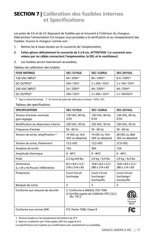
Tableaudecalibrationdesfusibles
FUSe RAtinGS Sec-1215UL Sec-1230UL Sec-2415UL
120VACINPUT 4A/250V* 8A/250V* 8A/250V*
DCOUTPUT 20A/32V† 2x20A/32V† 2x10A/32V†
230VACINPUT 2A/250V* 4A/250V* 4A/250V*
DCOUTPUT 20A/32V† 2x20A/32V† 2x10A/32V†
*Typeàretarddetemps.†Enformedepaledesvéhiculesàmoteur:l'ATO,ATC.
Tableaudesspécifications
SPeciFicAtionS Sec-1215UL Sec-1230UL Sec-2415UL
Tensiond’entréenominale (pré-réglage)
120VAC,60Hz,3,3A
120VAC,60Hz,6,5A
120VAC,60Hz,6,5A
Modificationdudisjoncteurinterne 230VAC,50Hz 230VAC,50Hz 230VAC,50Hz
Fréquenced’entrée 50-60Hz 50-60Hz 50-60Hz
Tensiondesortie,amplification1,2 14VDCou14,4VDCoudésactivé
14VDCou14,4VDCoudésactivé
28VDCou28,8VDCoudésactivé
Tensiondesortie,Flottement1 13,5VDC 13,5VDC 27,0VDC
Ampèresdesortie 15A 30A 15A
Amplitudethermique 0-40°C 0-40°C 0-40°C
Poids 2,2kg,/4,8lbs, 2,9kg./6,4lbs. 2,9kg./6,4lbs.
Dimensions(LxWxH)Pouces/Millimètres
8,5x8,4x3,3/218x214x83
10,8x8,4x3,3/280x214x83
10,8x8,4x3,3/280x214x83
Protections CourtCircuitSurcharge
CourtCircuitSurcharge/ Surchauffe
CourtCircuitSurcharge/ Surchauffe
Banquesdesortie 3 3 3
Conformeauxmesuresdesécurité i)ConformeàANSI/ULSTD1564ii)CertifiéauprèsdeCAN/USASTDC22,2 No,107,2
ConformeauxnormesEMI FCCPartie15(B),ClasseB
1,Tensionsbaséessurlestempératuresdebatteriede27°C
2,Basésurlasélectionparl’interrupteurDIP,Voirpages8et9
Lesspécificationssontsujettesauxmodificationssansavertissementaupréalable,
4004711
18 | SAMLEX AMERICA INC.
seCtion 8 | Warranty
GARAntie LiMitee SoUS 2 AnS
SEC-1215UL/SEC-1230ULetSEC-2415UL,fabriquésparSamlexAmerica,Inc.(le«Garant»)sontgarantisêtrenondéfectueuxdanslaconceptionetdanslesmatériaux,moyennantuneutilisationetunservicenormaux.Lapériodedegarantieestde2anspourlesEtats-UnisetleCanada,etprendeffetlejourdel’achatparl’utilisateur(«l’Acheteur»).
•LagarantiehorsdesEtatsUnisetduCanadaestlimitéeà6mois.Pouruneréclamationconcernantlagarantie,l’Acheteurdevracontacterlepointdeventeoul’achataétéeffectuéafind’obtenirunNumérod’AutorisationpourleRetour.
•Lapièceoul’unitédéfectueusedevraêtreretournéeauxfraisdel’acheteuraupointdeventeagrée.Unedéclarationécritedécrivantlanaturedudéfaut,ladateetlelieud’achatainsiquelenom,l’adresseetlenumérodetéléphonedel’Acheteurdevrontégalementêtrerenseignés.
•Sial’examinationdelademandeparleGarant,ledéfautestréellementlerésultatd’unmatériauoud’unassemblagedéfectueux,l’équipementseraréparéouremplacégratuitementetrenvoyéal’Acheteurauxfraisdu Garant.(Etats-UnisetCanadauniquement).
•Aucunremboursementduprixd’achatneseraaccordeal’Acheteur,saufsileGarantestincapablederemédieraudéfautaprèsavoireuplusieursoc-casiondelefaire.LeservicedegarantiedoitêtreeffectueuniquementparleGarant.Toutetentativesderemédieraudéfautparquelqu’und’autrequeleGarantrendentcettegarantienulleetsanseffet.Iln’existeaucunegarantieconcernantlesdéfautsoudommagescausésparuneinstallationdéfectueuseouinadaptée,parunabusouunemauvaiseutilisationdel’équipement,ycompris,uneexpositionexcessivealachaleur,ausel,auxéclaboussuresd’eaufraicheoual’immersiondansl’eau.
•Aucuneautregarantieexpressn’estaccordéeetiln’existeaucunesgarantiesquis’étendentaudelàdesconditionsdécritesparlaprésente.CettegarantieestlaseulegarantievalableetreconnueparleGarant,etprédominesurd’autresgarantieimplicites,ycomprislesgarantiesimplicitesliéesalagar-antiedequalitémarchande,al’usagedesobjectifshabituelspourlesquelsdetellesmarchandisessontutilisées,oul’usagepourunobjectifparticulier,outoutesautresobligationsdelapartduGarantoudesesemployésetreprésentants.
18 | SAMLEX AMERICA INC. SAMLEX AMERICA INC. | 19
seCtion 8 | Warranty
• IlnedoitpasexisterderesponsabilitéouautredelapartduGrantoudessesemployésetreprésentants,encequiconcernelesblessurescorporelles,oulesdommagesdepersonneapersonne,oulesdégâtssurunepropriété,oulapertederevenusoudebénéfices,ouautresdommagescollatéraux,pouvantêtrerapportéscommeayantsurvenusaucoursdel’utilisationoudelaventedumatériel,ycompristousdisfonctionnementsouéchecsdumatériel,ouunepartiedecelui-ci.LeGarantn’assumeaucuneresponsabilitéconcernanttoutessortesdedommagesaccidentelsouindirects.
Samlex America inc. (le « Garant »)www.samlexamerica.com

InformationContact
Numéros gratuitsTel : 1 800 561 5885Fax : 1 888 814 5210
Numéros locauxTel : 604 525 3836Fax : 604 525 5221
Site internetwww.samlexamerica.com
Entrepôt USA Kent, WA
Entrepôt CanadaDelta, BC
Adresse email pour passer commande
11001-SEC-1215-1230-2415UL-0513-FR


![Sealed Lead-Acid Battery Charger datasheet (Rev. C) · 2020. 12. 31. · Sealed Lead-Acid Battery Charger datasheet (Rev. C) Author: Texas Instruments, Incorporated [SLUS186,C ] Subject:](https://img.pdfslide.net/doc/110x75/610ffec508269627ff6a9729/sealed-lead-acid-battery-charger-datasheet-rev-c-2020-12-31-sealed-lead-acid.jpg)