Embed Size (px)
Citation preview
UNINTERRUPTIBLE POWER SUPPLY SYSTEM
MODEL
9700 SERIESOWNERS / TECHNICAL MANUAL
MITSUBISHIELECTRIC

Preface
MITSUBISHI ELECTRIC CORPORATION
Revision 3.32 Mar. 25, 08ALN-H0153
MITSUBISHI
ELECTRIC
9700 SERIES UPS
OWNERS / TECHNICAL MANUAL
Page Number:i
MITSUBISHI ELECTRIC 9700SERIES UPS
TABLE OF CONTENTS
LIST OF TABLES ............................................................................................ ii
LIST OF FIGURES .......................................................................................... iii
INTRODUCTION ............................................................................................. iv
SAFETY PRECAUSIONS ................................................................................ v
1.0 GENERAL .............................................................................................. 1-1
1.1 DEFINITIONS ......................................................................................... 1-2
1.2 OVERVIEW ............................................................................................. 1-3
1.3 SPECIFICATIONS .................................................................................. 1-9
2.0 OPERATION CONTROLS AND INDICATORS ...................... 2-1
2.1 LED DISPLAY ......................................................................................... 2-2
2.2 LIQUID CRYSTAL DISPLAY ................................................................... 2-3
2.3 EXTERNAL SIGNAL TERMINAL BLOCK ................................................ 2-9
2.4 EXTERNAL COMMUNICATION CONNECTOR ...................................... 2-12
3.0 INSTALLATION AND OPERATION ............................... 3-1
3.1 TRANSPORTATION AND INSTALLATION ............................................. 3-1
3.2 INSTALLATION PROCEDURE ............................................................... 3-1
3.3 PROCEDURE FOR CABLE CONNECTIONS .......................................... 3-2
3.4 OPERATING PROCEDURES ................................................................. 3-14
4.0 RESPONSE TO UPS FAILURE ................................... 4-1
5.0 PARTS REPLACEMENT ......................................... 5-1
6.0 FAULT CODES ................................................. 6-1
7.0 WARRANTY & OUT OF WARRANTY SERVICE .................... 7-1
MITSUBISHI
ELECTRIC
9700 SERIES UPS
OWNERS / TECHNICAL MANUAL
Page Number:ii
MITSUBISHI ELECTRIC 9700SERIES UPS
List of Tables
Table 1.1 Power Specifications.................................................................. 1-9
Table 1.2 UPS Module Information............................................................ 1-9
Table 1.3 Detail of Specifications............................................................... 1-10
Table 1.4 Rating of Contactors / Circuit Breakers and Fuses ..................... 1-11
Table 3.1 How to Transport and Install the System.................................... 3-1
Table 3.2 List of UPS Weights (lb.) ............................................................ 3-1
Table 3.3 Maximum Permitted Fault Current.............................................. 3-2
Table 3.4 Recommended Cable Size and.................................................. 3-5
Torque Requirements
Table 3.5 Crimp Type Compression Lug.................................................... 3-6
MITSUBISHI
ELECTRIC
9700 SERIES UPS
OWNERS / TECHNICAL MANUAL
Page Number:iii
MITSUBISHI ELECTRIC 9700SERIES UPS
List of Figures
Figure 1.1 Single Line Diagram-Normal Operation...................................... 1-3
Figure 1.2 Single Line Diagram-Bypass Operation...................................... 1-4
Figure 1.3 Single Line Diagram-Battery Operation ...................................... 1-4
Figure 1.4 UPS Parts Location.................................................................... 1-6
Figure 2.1 Operation/Display Panel ............................................................ 2-1
Figure 2.2 Main Screen .............................................................................. 2-3
Figure 2.3 Bypass Screen........................................................................... 2-3
Figure 2.4 Input Screen .............................................................................. 2-4
Figure 2.5 Output Voltage Screen............................................................... 2-4
Figure 2.6 Output Current Screen............................................................... 2-4
Figure 2.7 Trend Graph Screen .................................................................. 2-5
Figure 2.8 Battery Screen........................................................................... 2-5
Figure 2.9 Remote / Local Selection Screen ............................................... 2-5
Figure 2.10 Operation Menu Screen............................................................. 2-6
Figure 2.11 Battery Operation Screen........................................................... 2-7
Figure 2.12 Battery Low Voltage Screen....................................................... 2-7
Figure 2.13 Discharge Termination Screen................................................... 2-7
Figure 2.14 Fault Indication Screen .............................................................. 2-8
Figure 2.15 External Signal Terminal Block .................................................. 2-9
Figure 2.16 Control Wiring for External Contacts .......................................... 2-10
Figure 2.17 Remote "Start" Contact Connections.......................................... 2-11
Figure 2.18 External communication connector ............................................ 2-12
Figure 3.1 UPS Terminal Designation......................................................... 3-7
Figure 3.2 Diagram of input/output Terminals ............................................. 3-8
Figure 3.3 Start-up Menu............................................................................ 3-14
Figure 3.4 Inverter Start / Stop.................................................................... 3-14
MITSUBISHI
ELECTRIC
9700 SERIES UPS
OWNERS / TECHNICAL MANUAL
Page Number:iv
MITSUBISHI ELECTRIC 9700SERIES UPS
INTRODUCTION
Your Mitsubishi Uninterruptible Power Supply System (UPS) is designed to provide many
years of reliable protection from power failure, brown-outs, line noise, and voltage transients.
To ensure optimum performance of the equipment, follow the manufacturer's instructions. This
manual contains descriptions required to operate the UPS. Please read this manual carefully
and retain it for future reference.
This manual contains important instructions for the 9700 SERIES Uninterruptible Power Supply
Systems that should be followed during installation and maintenance of the UPS and batteries.
Lethal voltages exist within the equipment during operation. Observe
all warning and cautions in this manual. Failure to comply may result
in serious injury or death. Obtain qualified service for this equipment
as instructed.
IMPORTANT SAFETY INSTRUCTIONS
SAVE THESE INSTRUCTIONS
WARNING 1
MITSUBISHI
ELECTRIC
9700 SERIES UPS
OWNERS / TECHNICAL MANUAL
Page Number:v
MITSUBISHI ELECTRIC 9700SERIES UPS
In no event will MITSUBISHI be responsible or liable for either indirect orconsequential damage or injury that may come from the use of this equipment.
Any modifications without authorization by MITSUBISHI could result in personal
injuries, death or destruction of the UPS.
SAFETY PRECAUTIONS
APPLICATION
Special considerations are required when applying this UPS to theequipment (**) that affect human safety and/or maintain public services.
This UPS shall NOT be applied to support equipment (*) that could affectthe human lives, such as:
* Medical operation room equipment
Life support equipment (artificial dialysis, incubators, etc.)
Toxic gas or smoke eliminators
Equipment that must be provided under fire laws, construction standardsor other ordinances
Equipment equivalent to the above
** Equipment to supervise or control airways, railways, roads, sea-lanesor other transportation.
Equipment in nuclear power plants.
Equipment to control communications.
Equipment equivalent/similar to the above mentioned.
WARNING 2

MITSUBISHI
ELECTRIC
9700 SERIES UPS
OWNERS / TECHNICAL MANUAL
Page Number:vi
MITSUBISHI ELECTRIC 9700SERIES UPS
The UPS is to be installed in a controlled environment.
Improper storage and installation environment may deteriorateinsulation, shorten component life and cause malfunctions.
Keep the installation environment per standard described as follows:
UPS Installation Environment
No. Item Environment standard
1 Installationlocation
Indoors
2 Ambienttemperature
Minimum temperature: 32F(0C), Maximum temperature: 104F(40C) Theaverage temperature over any 24-hour period must be in the range 41 F (5C)to 95F(35C).
3 Relativehumidity
The relative humidity must be held between 5 and 95%. There must be nocondensation due to temperature changes.
4 Altitude This equipment must not be applied at altitude that exceeds 1520m(5000ft)above seal level.
5 Dust Dust in the room where the UPS is installed must not exceed normalatmospheric dust levels. In particular, that dust shoud not include iron particles,oils or fats, or organic materials such as silicone.
There should be no inflammable/explosive gas.
Hydrogen sulfide (H2S) No more than 0.003 PPM
Sulfurous acid gas (SO2) No more than 0.01 PPM
Chlorine gas (Cl2) No more than 0.0005 PPM
Ammonia gas (NH3) No more than 1 PPM
Hydrogen fluoride (HF) No more than 0.001 PPM
Nitrous oxides (NOx) No more than 0.05 PPM
6 Inflammable gas
Ozone (O3) No more than 0.002 PPM
WARNING 3

MITSUBISHI
ELECTRIC
9700 SERIES UPS
OWNERS / TECHNICAL MANUAL
Page Number:vii
MITSUBISHI ELECTRIC 9700SERIES UPS
This UPS does not include a Bypass Input circuit breaker (MCCB).
The Bypass Input contactor (CB3) does not protect against load
induced short circuits. The bypass input circuit breaker (MCCB) is
field supplied and installed. Breaker(MCCB)'s Specifications are as
follows:
Capacity (kVA) Bypass Voltage (VAC) Maximum Bypass
Rating (AAC)
Recommended
Breaker (A)
100 208 278 350
150 208 416 500
225 208 625 700
WARNING 4

MITSUBISHI
ELECTRIC
9700 SERIES UPS
OWNERS / TECHNICAL MANUAL
Page Number:1-1
MITSUBISHI ELECTRIC 9700 SERIES UPS
1.0 GENERAL
The Mitsubishi 9700 Series UPS is designed to provide continuous, clean electrical power
to your critical load and to monitor power conditions affecting that load. In the event of an
input power failure, the UPS will supply power to the critical load for the specified battery
time.
If the input power is not restored promptly, back up power from the UPS battery permits
the orderly shutdown of equipment supported by the UPS. The UPS is simple to start-up,
operate and maintain.
The 9700 Series UPS is available in three kVA sizes-100, 150, 225kVA. Specifications
for each kVA model appear in Section 1.3. The principles of operation described herein
are applicable to all models.
This manual provides an overview of the 9700 Series components and their functions. It
describes the appearance and purpose of operator controls and indicators. It contains
procedures for operation, start-up, shutdown, and basic maintenance.
MITSUBISHI
ELECTRIC
9700 SERIES UPS
OWNERS / TECHNICAL MANUAL
Page Number:1-2
MITSUBISHI ELECTRIC 9700 SERIES UPS
1.1 Definitions
UNINTERRUPTIBLE POWER SUPPLY SYSTEM (UPS) - All components within the UPS
Module Cabinet includes the batteries which function as a system to provide continuous,
conditioned AC power to a load. This is sometimes referred to as the "System".
UPS MODULE CABINET - The metal enclosure which contains the Converter / Charger,
the Inverter, the Static Transfer Switch, the Internal Bypass line, the operator controls, and
the internal control system required to provide specified AC power to a load.
UPS MODULE - The Converter / Charger and Inverter assemblies which, under the
direction of the internal control system and operator controls, provide specified AC power
to a load.
CONVERTER / CHARGER - The UPS components which contain the equipment and
controls necessary to convert input AC power to regulated DC power required for battery
charging and for supplying power to the Inverter.
INVERTER - The UPS components which contain the equipment and controls necessary
to convert DC power from the Converter / Charger, or the battery, to AC power required by
the critical load.
STATIC TRANSFER SWITCH - The device which connects the critical load to the bypass
line when the UPS module cannot supply continuous power.
BYPASS LINE - The line which conducts electricity directly from the input power source to the
critical load during Maintenance or whenever the UPS is not completely operational.
INPUT POWER - Power provided by the electrical utility company, or auxiliary generator,
which is connected to the UPS for supplying the critical load.
MITSUBISHI
ELECTRIC
9700 SERIES UPS
OWNERS / TECHNICAL MANUAL
Page Number:1-3
MITSUBISHI ELECTRIC 9700 SERIES UPS
1.2 Overview
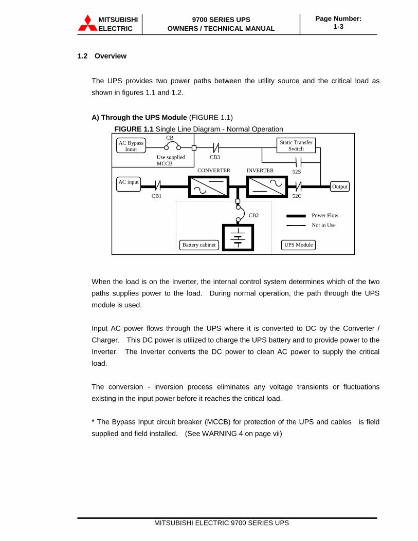
The UPS provides two power paths between the utility source and the critical load as
shown in figures 1.1 and 1.2.
A) Through the UPS Module (FIGURE 1.1)
FIGURE 1.1 Single Line Diagram - Normal Operation
When the load is on the Inverter, the internal control system determines which of the two
paths supplies power to the load. During normal operation, the path through the UPS
module is used.
Input AC power flows through the UPS where it is converted to DC by the Converter /
Charger. This DC power is utilized to charge the UPS battery and to provide power to the
Inverter. The Inverter converts the DC power to clean AC power to supply the critical
load.
The conversion - inversion process eliminates any voltage transients or fluctuations
existing in the input power before it reaches the critical load.
* The Bypass Input circuit breaker (MCCB) for protection of the UPS and cables is field
supplied and field installed. (See WARNING 4 on page vii)
Static TransferSwitch
AC BypassInput
OutputAC input
CB
CB3
52S
52C
Use suppliedMCCB
UPS ModuleBattery cabinet
CB1
CB2 Power Flow
Not in Use
CONVERTER INVERTER
MITSUBISHI
ELECTRIC
9700 SERIES UPS
OWNERS / TECHNICAL MANUAL
Page Number:1-4
MITSUBISHI ELECTRIC 9700 SERIES UPS
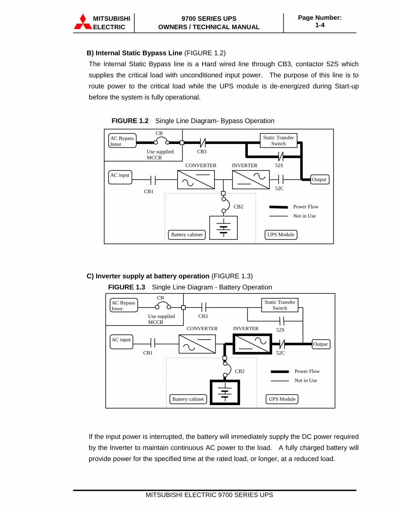
B) Internal Static Bypass Line (FIGURE 1.2)
The Internal Static Bypass line is a Hard wired line through CB3, contactor 52S which
supplies the critical load with unconditioned input power. The purpose of this line is to
route power to the critical load while the UPS module is de-energized during Start-up
before the system is fully operational.
FIGURE 1.2 Single Line Diagram- Bypass Operation
C) Inverter supply at battery operation (FIGURE 1.3)
FIGURE 1.3 Single Line Diagram - Battery Operation
If the input power is interrupted, the battery will immediately supply the DC power required
by the Inverter to maintain continuous AC power to the load. A fully charged battery will
provide power for the specified time at the rated load, or longer, at a reduced load.
Static TransferSwitch
AC BypassInput
OutputAC input
CB
CB3
52S
52C
Use suppliedMCCB
UPS ModuleBattery cabinet
CB1
CB2 Power Flow
Not in Use
CONVERTER INVERTER
Static TransferSwitch
AC BypassInput
OutputAC input
CB
CB3
52S
52C
Use suppliedMCCB
UPS ModuleBattery cabinet
CB1
CB2 Power Flow
Not in Use
CONVERTER INVERTER
MITSUBISHI
ELECTRIC
9700 SERIES UPS
OWNERS / TECHNICAL MANUAL
Page Number:1-5
MITSUBISHI ELECTRIC 9700 SERIES UPS
When power is restored after a low battery shutdown, the Converter automatically restarts
operation, recharges the batteries, and the Inverter is automatically restarted without
operator intervention. The load is assumed by the inverter automatically without
operator intervention.
In the event of a power failure, the rectifier will de-energize and the batteries will discharge
into the inverter and maintain power to the critical until a) the battery capacity expires and
the inverter turns off, or b) input power is restored after which the converter will power the
critical load and simultaneously recharge the batteries. Figure 1.3 illustrates the flow
diagram during battery operation.
MITSUBISHI
ELECTRIC
9700 SERIES UPS
OWNERS / TECHNICAL MANUAL
Page Number:1-6
MITSUBISHI ELECTRIC 9700 SERIES UPS
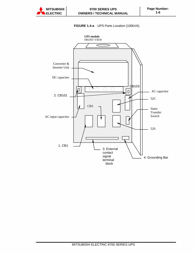
FIGURE 1.4-a UPS Parts Location (100kVA)
52S
3. Externalcontactsignalterminal
block
AC capacitor
UPS moduleFRONT VIEW
1. CB1
CB3
52C
Converter &Inverter Unit
StaticTransferSwitch
4. Grounding Bar
DC capacitor
2. CB101
AC input capacitor
CB103
MITSUBISHI
ELECTRIC
9700 SERIES UPS
OWNERS / TECHNICAL MANUAL
Page Number:1-7
MITSUBISHI ELECTRIC 9700 SERIES UPS
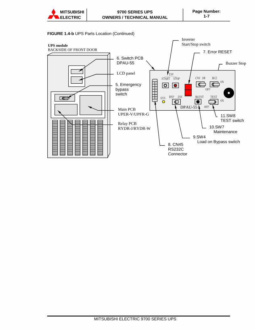
FIGURE 1.4-b UPS Parts Location (Continued)
Buzzer Stop
UPS moduleBACKSIDE OF FRONT DOOR
10.SW7Maintenance
9.SW4Load on Bypass switch
7. Error RESET
11.SW8TEST switch
DPAU-55
8. CN45RS232CConnector
6. Switch PCBDPAU-55
Main PCBUPER-V/UPFR-G
LCD panel
5. Emergencybypassswitch
Relay PCBRYDR-J/RYDR-W
CNV SW BUZON
OFF
MAINT TESTON
OFF
INV
START STOP
BYP INVSYN
InverterStart/Stop switch
MITSUBISHI
ELECTRIC
9700 SERIES UPS
OWNERS / TECHNICAL MANUAL
Page Number:1-8
MITSUBISHI ELECTRIC 9700 SERIES UPS
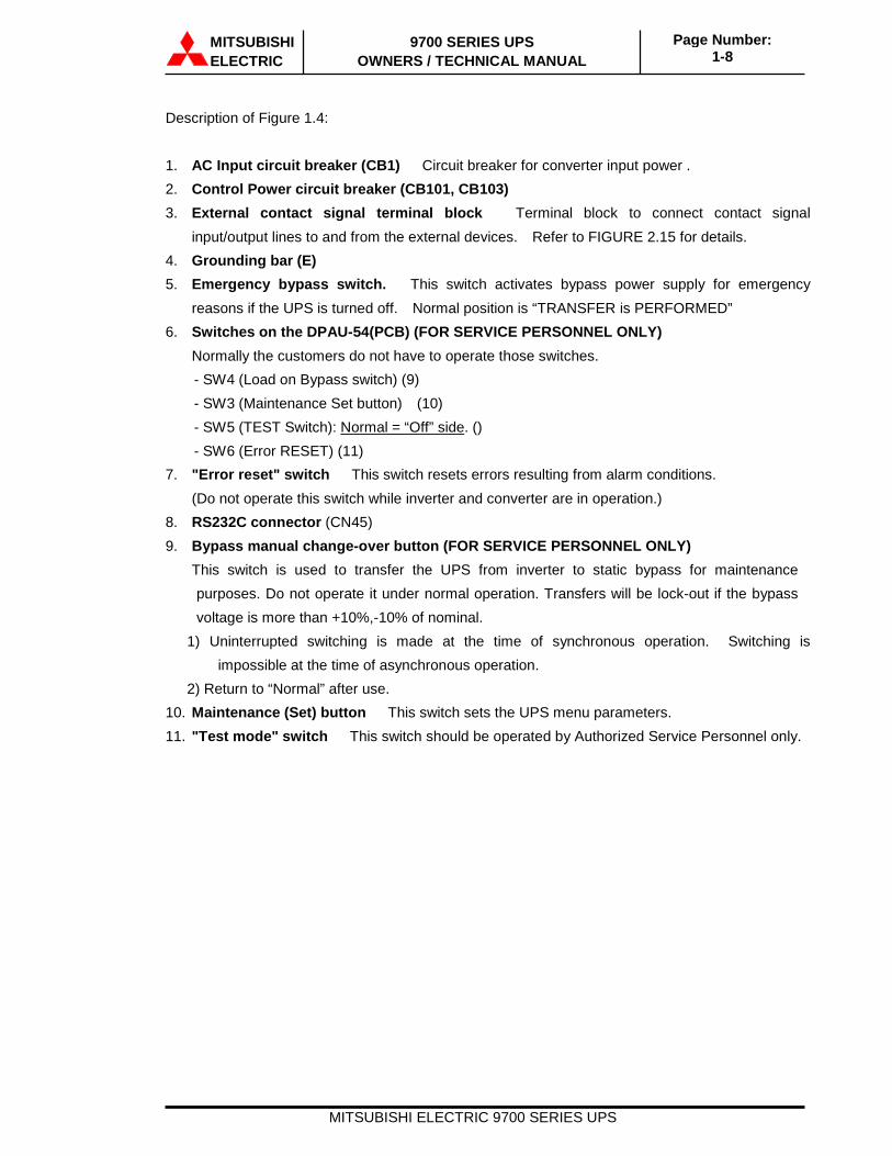
Description of Figure 1.4:
1. AC Input circuit breaker (CB1) Circuit breaker for converter input power .
2. Control Power circuit breaker (CB101, CB103)
3. External contact signal terminal block Terminal block to connect contact signal
input/output lines to and from the external devices. Refer to FIGURE 2.15 for details.
4. Grounding bar (E)
5. Emergency bypass switch. This switch activates bypass power supply for emergency
reasons if the UPS is turned off. Normal position is “TRANSFER is PERFORMED”
6. Switches on the DPAU-54(PCB) (FOR SERVICE PERSONNEL ONLY)
Normally the customers do not have to operate those switches.
- SW4 (Load on Bypass switch) (9)
- SW3 (Maintenance Set button) (10)
- SW5 (TEST Switch): Normal = “Off” side. ()
- SW6 (Error RESET) (11)
7. "Error reset" switch This switch resets errors resulting from alarm conditions.
(Do not operate this switch while inverter and converter are in operation.)
8. RS232C connector (CN45)
9. Bypass manual change-over button (FOR SERVICE PERSONNEL ONLY)
This switch is used to transfer the UPS from inverter to static bypass for maintenance
purposes. Do not operate it under normal operation. Transfers will be lock-out if the bypass
voltage is more than +10%,-10% of nominal.
1) Uninterrupted switching is made at the time of synchronous operation. Switching is
impossible at the time of asynchronous operation.
2) Return to “Normal” after use.
10. Maintenance (Set) button This switch sets the UPS menu parameters.
11. "Test mode" switch This switch should be operated by Authorized Service Personnel only.
MITSUBISHI
ELECTRIC
9700 SERIES UPS
OWNERS / TECHNICAL MANUAL
Page Number:1-9
MITSUBISHI ELECTRIC 9700 SERIES UPS
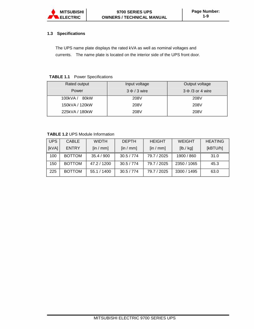
1.3 Specifications
The UPS name plate displays the rated kVA as well as nominal voltages and
currents. The name plate is located on the interior side of the UPS front door.
TABLE 1.1 Power Specifications
Rated output
Power
Input voltage
3 / 3 wire
Output voltage
3 /3 or 4 wire
100kVA / 80kW
150kVA / 120kW
225kVA / 180kW
208V
208V
208V
208V
208V
208V
TABLE 1.2 UPS Module Information
UPS
[kVA]
CABLE
ENTRY
WIDTH
[in / mm]
DEPTH
[in / mm]
HEIGHT
[in / mm]
WEIGHT
[lb./ kg]
HEATING
[kBTU/h]
100 BOTTOM 35.4 / 900 30.5 / 774 79.7 / 2025 1900 / 860 31.0
150 BOTTOM 47.2 / 1200 30.5 / 774 79.7 / 2025 2350 / 1065 45.3
225 BOTTOM 55.1 / 1400 30.5 / 774 79.7 / 2025 3300 / 1495 63.0
MITSUBISHI
ELECTRIC
9700 SERIES UPS
OWNERS / TECHNICAL MANUAL
Page Number:1-10
MITSUBISHI ELECTRIC 9700 SERIES UPS
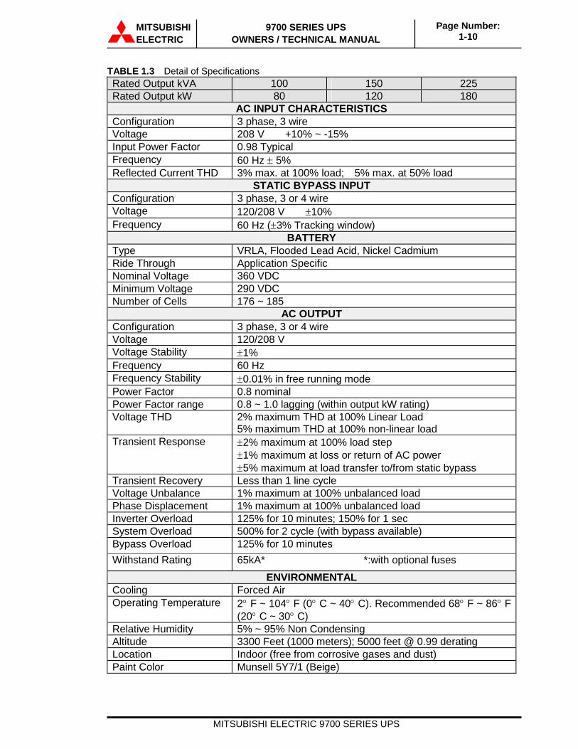
TABLE 1.3 Detail of Specifications
Rated Output kVA 100 150 225Rated Output kW 80 120 180
AC INPUT CHARACTERISTICSConfiguration 3 phase, 3 wireVoltage 208 V +10% ~ -15%Input Power Factor 0.98 TypicalFrequency 60 Hz 5%Reflected Current THD 3% max. at 100% load; 5% max. at 50% load
STATIC BYPASS INPUTConfiguration 3 phase, 3 or 4 wireVoltage 120/208 V 10%Frequency 60 Hz (3% Tracking window)
BATTERYType VRLA, Flooded Lead Acid, Nickel CadmiumRide Through Application SpecificNominal Voltage 360 VDCMinimum Voltage 290 VDCNumber of Cells 176 ~ 185
AC OUTPUTConfiguration 3 phase, 3 or 4 wireVoltage 120/208 VVoltage Stability 1%Frequency 60 HzFrequency Stability 0.01% in free running modePower Factor 0.8 nominalPower Factor range 0.8 ~ 1.0 lagging (within output kW rating)Voltage THD 2% maximum THD at 100% Linear Load
5% maximum THD at 100% non-linear loadTransient Response 2% maximum at 100% load step
1% maximum at loss or return of AC power5% maximum at load transfer to/from static bypass
Transient Recovery Less than 1 line cycleVoltage Unbalance 1% maximum at 100% unbalanced loadPhase Displacement 1% maximum at 100% unbalanced loadInverter Overload 125% for 10 minutes; 150% for 1 secSystem Overload 500% for 2 cycle (with bypass available)Bypass Overload 125% for 10 minutes
Withstand Rating 65kA* *:with optional fuses
ENVIRONMENTALCooling Forced AirOperating Temperature 2 F ~ 104 F (0 C ~ 40 C). Recommended 68 F ~ 86 F
(20 C ~ 30 C)Relative Humidity 5% ~ 95% Non CondensingAltitude 3300 Feet (1000 meters); 5000 feet @ 0.99 deratingLocation Indoor (free from corrosive gases and dust)Paint Color Munsell 5Y7/1 (Beige)
MITSUBISHI
ELECTRIC
9700 SERIES UPS
OWNERS / TECHNICAL MANUAL
Page Number:1-11
MITSUBISHI ELECTRIC 9700 SERIES UPS
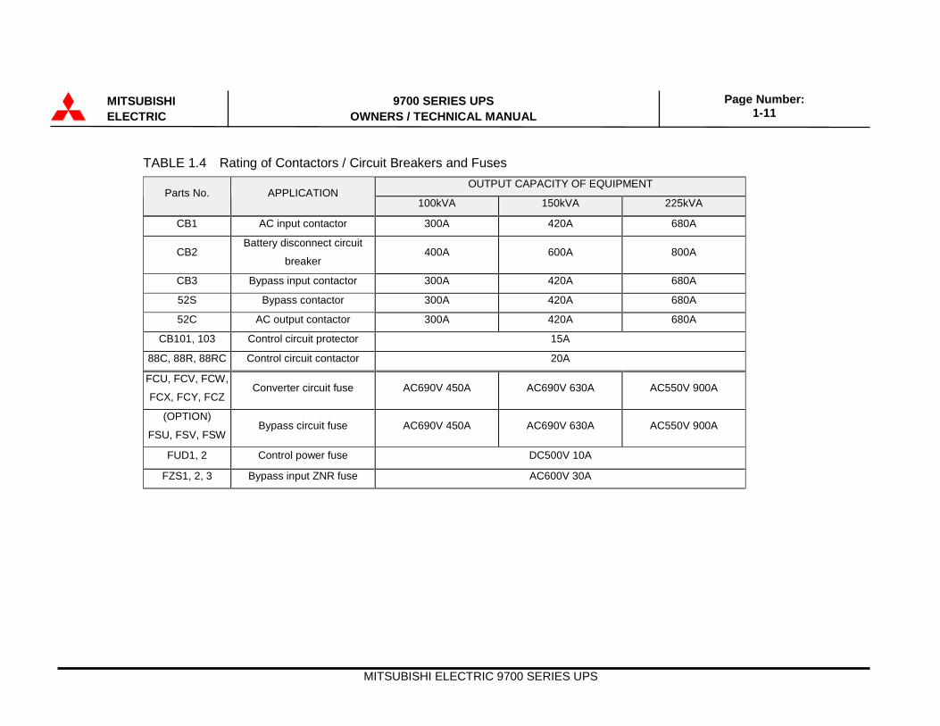
TABLE 1.4 Rating of Contactors / Circuit Breakers and Fuses
OUTPUT CAPACITY OF EQUIPMENTParts No. APPLICATION
100kVA 150kVA 225kVA
CB1 AC input contactor 300A 420A 680A
CB2Battery disconnect circuit
breaker400A 600A 800A
CB3 Bypass input contactor 300A 420A 680A
52S Bypass contactor 300A 420A 680A
52C AC output contactor 300A 420A 680A
CB101, 103 Control circuit protector 15A
88C, 88R, 88RC Control circuit contactor 20A
FCU, FCV, FCW,
FCX, FCY, FCZConverter circuit fuse AC690V 450A AC690V 630A AC550V 900A
(OPTION)
FSU, FSV, FSWBypass circuit fuse AC690V 450A AC690V 630A AC550V 900A
FUD1, 2 Control power fuse DC500V 10A
FZS1, 2, 3 Bypass input ZNR fuse AC600V 30A
MITSUBISHI
ELECTRIC
9700 SERIES UPS
OWNERS / TECHNICAL MANUAL
Page Number:2-1
MITSUBISHI ELECTRIC 9700 SERIES UPS
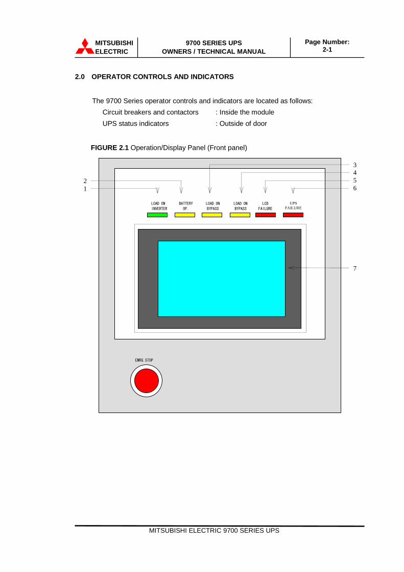
2.0 OPERATOR CONTROLS AND INDICATORS
The 9700 Series operator controls and indicators are located as follows:
Circuit breakers and contactors : Inside the module
UPS status indicators : Outside of door
FIGURE 2.1 Operation/Display Panel (Front panel)
EMRG.STOP
LOAD ON
INVERTER
BATTERY
OP.
LOAD ON
BYPASS
LCD
FAILURE
UPSFAILURE
7
3456
21
LOAD ON
BYPASS
MITSUBISHI
ELECTRIC
9700 SERIES UPS
OWNERS / TECHNICAL MANUAL
Page Number:2-2
MITSUBISHI ELECTRIC 9700 SERIES UPS
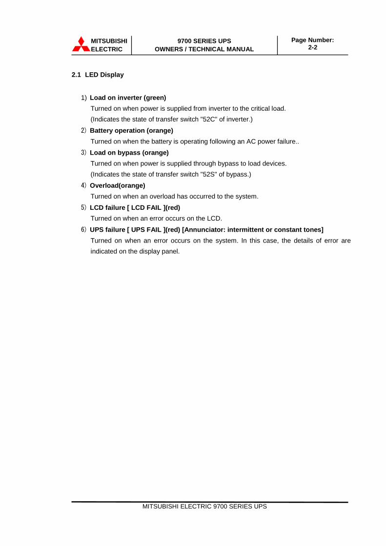
2.1 LED Display
1) Load on inverter (green)
Turned on when power is supplied from inverter to the critical load.
(Indicates the state of transfer switch "52C" of inverter.)
2) Battery operation (orange)
Turned on when the battery is operating following an AC power failure..
3) Load on bypass (orange)
Turned on when power is supplied through bypass to load devices.
(Indicates the state of transfer switch "52S" of bypass.)
4) Overload(orange)
Turned on when an overload has occurred to the system.
5) LCD failure [ LCD FAIL ](red)
Turned on when an error occurs on the LCD.
6) UPS failure [ UPS FAIL ](red) [Annunciator: intermittent or constant tones]
Turned on when an error occurs on the system. In this case, the details of error are
indicated on the display panel.
MITSUBISHI
ELECTRIC
9700 SERIES UPS
OWNERS / TECHNICAL MANUAL
Page Number:2-3
MITSUBISHI ELECTRIC 9700 SERIES UPS
2.2 Liquid Crystal Display (7)
The Liquid Crystal Display (LCD) panel indicates the power flow, measured values,
operational guidance, data record and error messages. The LCD panel is back-lit to
facilitate viewing in different ambient lighting conditions. The LCD will automatically clear if
the keyboard is not activated for 3 minutes. The ERROR indicator is cleared after 24
hours and can be reproduced by pressing any key on the panel.
2.2.1 Menu’s
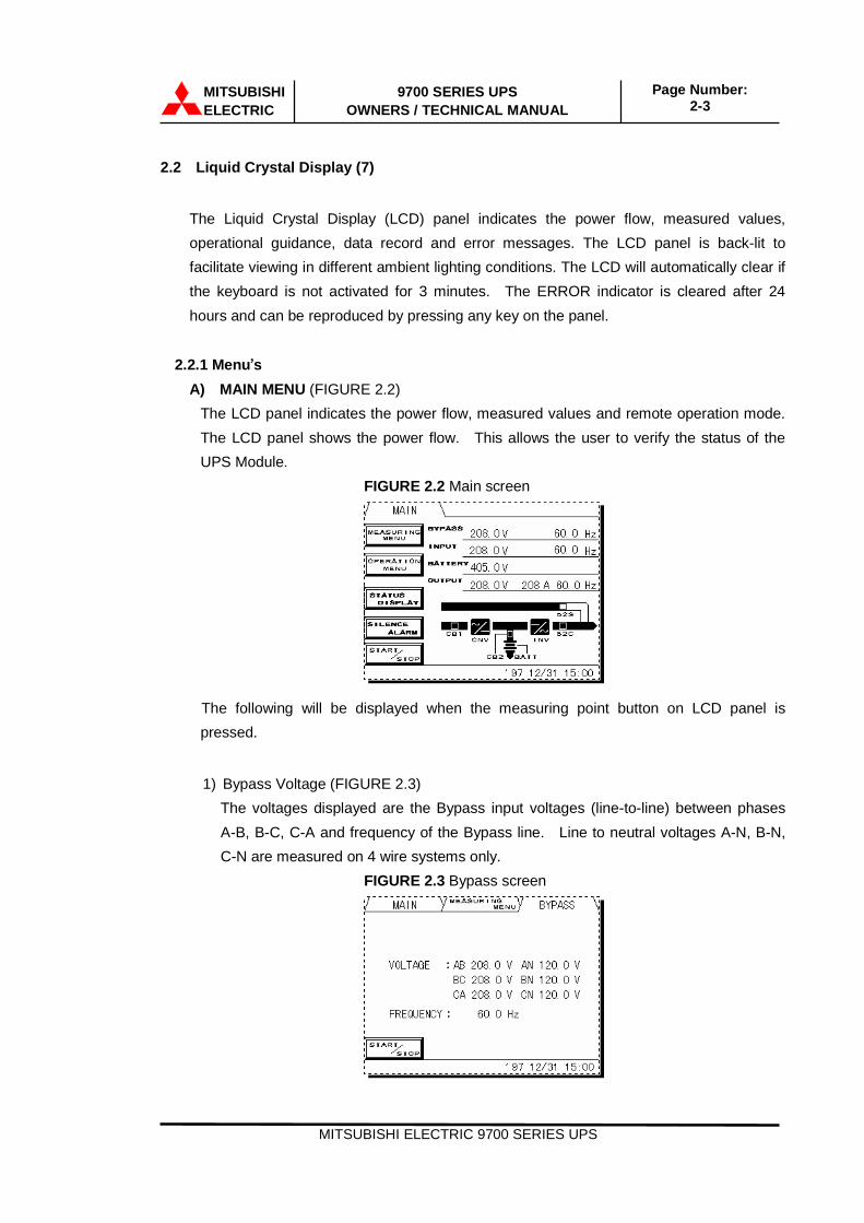
A) MAIN MENU (FIGURE 2.2)
The LCD panel indicates the power flow, measured values and remote operation mode.
The LCD panel shows the power flow. This allows the user to verify the status of the
UPS Module.
FIGURE 2.2 Main screen
The following will be displayed when the measuring point button on LCD panel is
pressed.
1) Bypass Voltage (FIGURE 2.3)
The voltages displayed are the Bypass input voltages (line-to-line) between phases
A-B, B-C, C-A and frequency of the Bypass line. Line to neutral voltages A-N, B-N,
C-N are measured on 4 wire systems only.
FIGURE 2.3 Bypass screen
MITSUBISHI
ELECTRIC
9700 SERIES UPS
OWNERS / TECHNICAL MANUAL
Page Number:2-4
MITSUBISHI ELECTRIC 9700 SERIES UPS
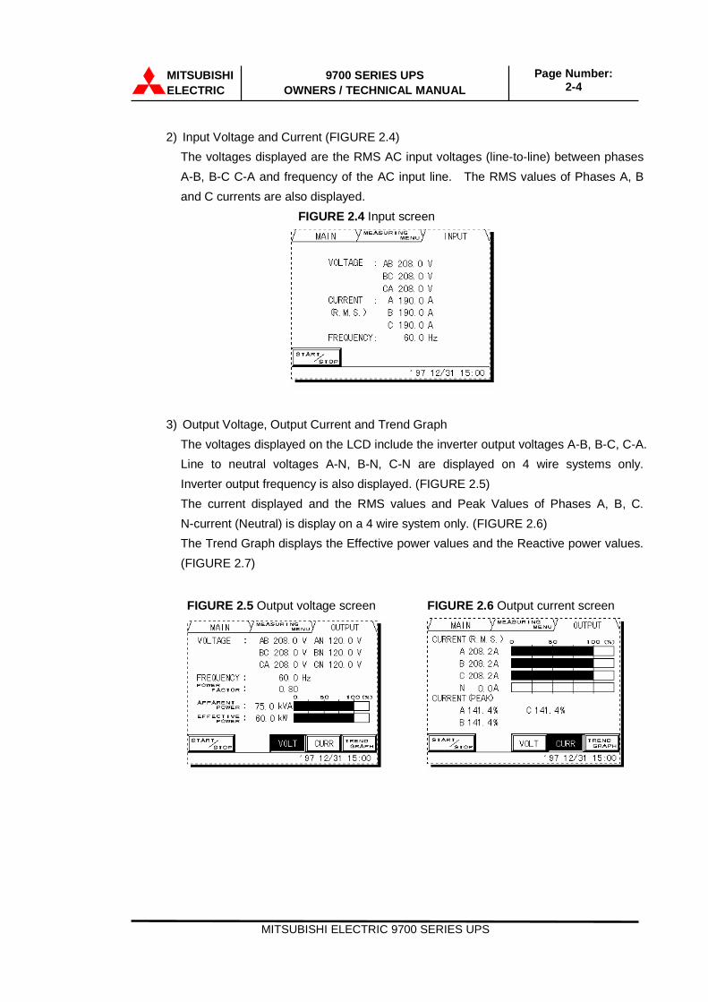
2) Input Voltage and Current (FIGURE 2.4)
The voltages displayed are the RMS AC input voltages (line-to-line) between phases
A-B, B-C C-A and frequency of the AC input line. The RMS values of Phases A, B
and C currents are also displayed.
FIGURE 2.4 Input screen
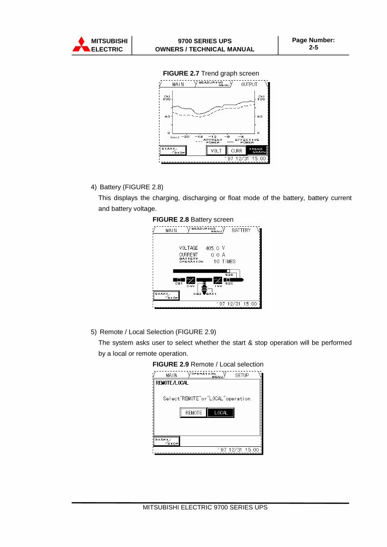
3) Output Voltage, Output Current and Trend Graph
The voltages displayed on the LCD include the inverter output voltages A-B, B-C, C-A.
Line to neutral voltages A-N, B-N, C-N are displayed on 4 wire systems only.
Inverter output frequency is also displayed. (FIGURE 2.5)
The current displayed and the RMS values and Peak Values of Phases A, B, C.
N-current (Neutral) is display on a 4 wire system only. (FIGURE 2.6)
The Trend Graph displays the Effective power values and the Reactive power values.
(FIGURE 2.7)
FIGURE 2.5 Output voltage screen FIGURE 2.6 Output current screen
MITSUBISHI
ELECTRIC
9700 SERIES UPS
OWNERS / TECHNICAL MANUAL
Page Number:2-5
MITSUBISHI ELECTRIC 9700 SERIES UPS
FIGURE 2.7 Trend graph screen
4) Battery (FIGURE 2.8)
This displays the charging, discharging or float mode of the battery, battery current
and battery voltage.
FIGURE 2.8 Battery screen
5) Remote / Local Selection (FIGURE 2.9)
The system asks user to select whether the start & stop operation will be performed
by a local or remote operation.
FIGURE 2.9 Remote / Local selection
MITSUBISHI
ELECTRIC
9700 SERIES UPS
OWNERS / TECHNICAL MANUAL
Page Number:2-6
MITSUBISHI ELECTRIC 9700 SERIES UPS
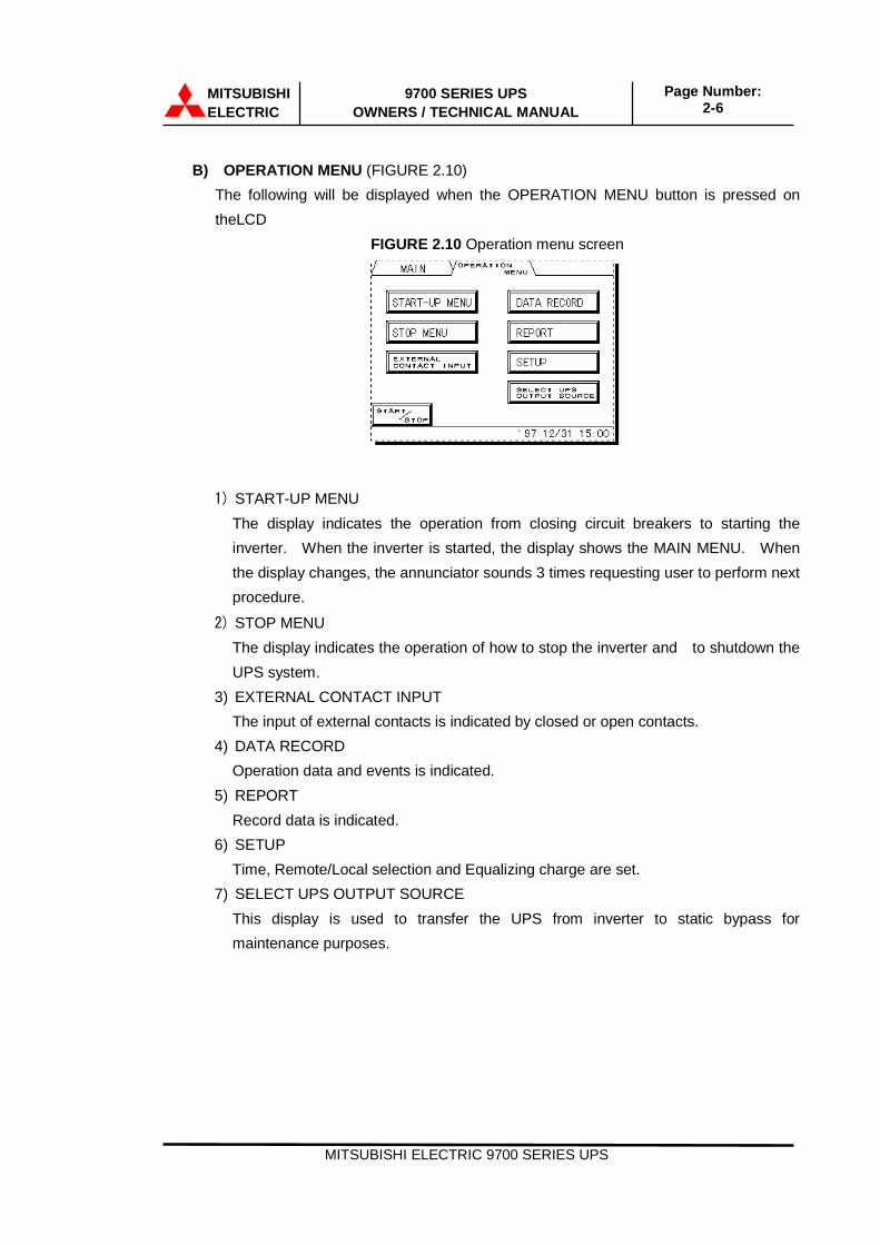
B) OPERATION MENU (FIGURE 2.10)
The following will be displayed when the OPERATION MENU button is pressed on
theLCD
FIGURE 2.10 Operation menu screen
1) START-UP MENU
The display indicates the operation from closing circuit breakers to starting the
inverter. When the inverter is started, the display shows the MAIN MENU. When
the display changes, the annunciator sounds 3 times requesting user to perform next
procedure.
2) STOP MENU
The display indicates the operation of how to stop the inverter and to shutdown the
UPS system.
3) EXTERNAL CONTACT INPUT
The input of external contacts is indicated by closed or open contacts.
4) DATA RECORD
Operation data and events is indicated.
5) REPORT
Record data is indicated.
6) SETUP
Time, Remote/Local selection and Equalizing charge are set.
7) SELECT UPS OUTPUT SOURCE
This display is used to transfer the UPS from inverter to static bypass for
maintenance purposes.
MITSUBISHI
ELECTRIC
9700 SERIES UPS
OWNERS / TECHNICAL MANUAL
Page Number:2-7
MITSUBISHI ELECTRIC 9700 SERIES UPS
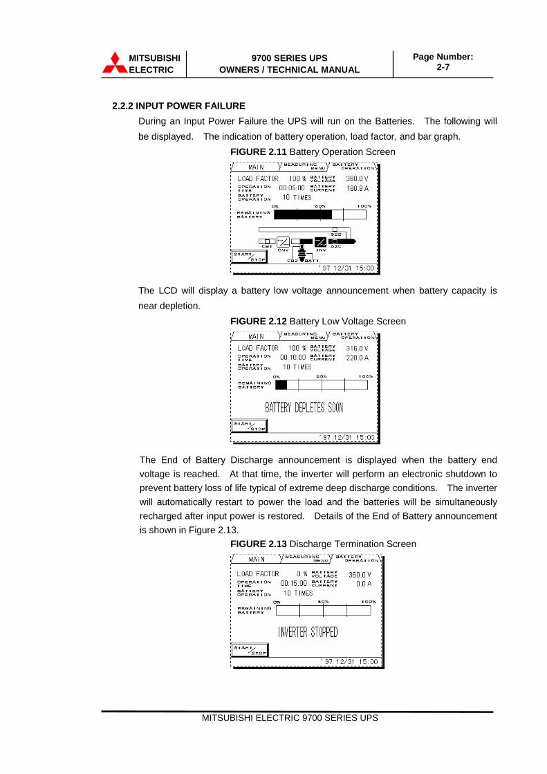
2.2.2 INPUT POWER FAILURE
During an Input Power Failure the UPS will run on the Batteries. The following will
be displayed. The indication of battery operation, load factor, and bar graph.
FIGURE 2.11 Battery Operation Screen
The LCD will display a battery low voltage announcement when battery capacity is
near depletion.
FIGURE 2.12 Battery Low Voltage Screen
The End of Battery Discharge announcement is displayed when the battery end
voltage is reached. At that time, the inverter will perform an electronic shutdown to
prevent battery loss of life typical of extreme deep discharge conditions. The inverter
will automatically restart to power the load and the batteries will be simultaneously
recharged after input power is restored. Details of the End of Battery announcement
is shown in Figure 2.13.
FIGURE 2.13 Discharge Termination Screen
MITSUBISHI
ELECTRIC
9700 SERIES UPS
OWNERS / TECHNICAL MANUAL
Page Number:2-8
MITSUBISHI ELECTRIC 9700 SERIES UPS
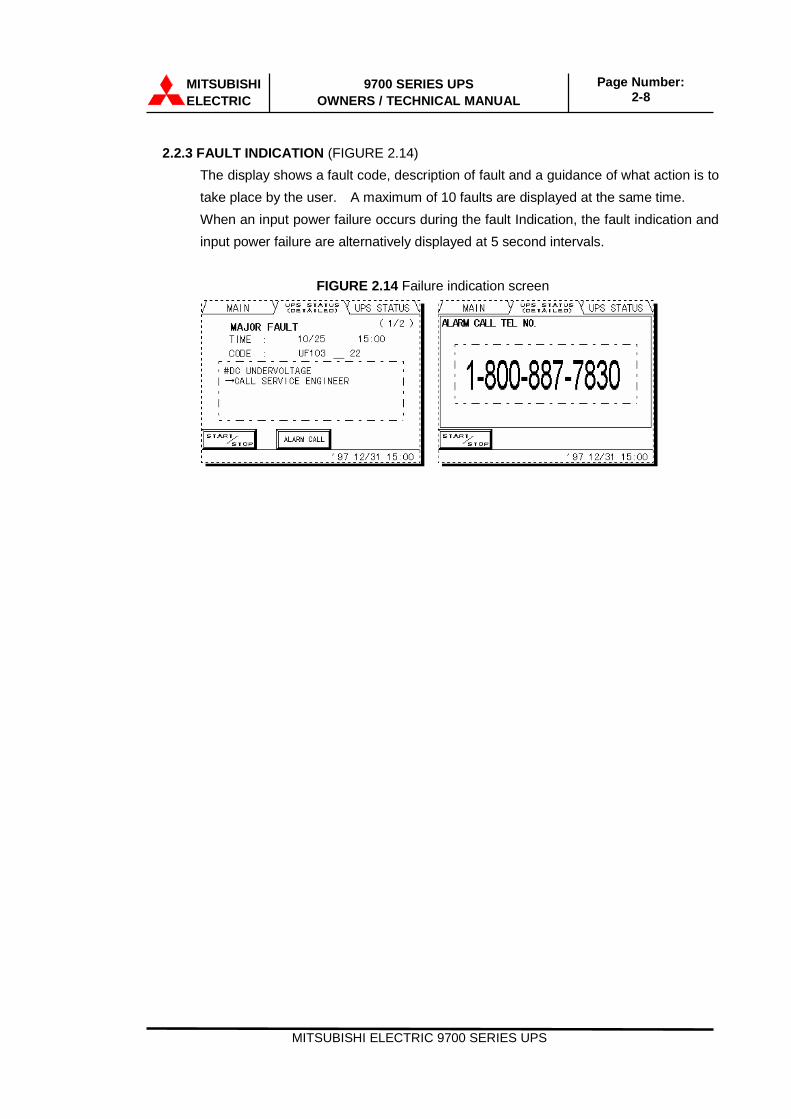
2.2.3 FAULT INDICATION (FIGURE 2.14)
The display shows a fault code, description of fault and a guidance of what action is to
take place by the user. A maximum of 10 faults are displayed at the same time.
When an input power failure occurs during the fault Indication, the fault indication and
input power failure are alternatively displayed at 5 second intervals.
FIGURE 2.14 Failure indication screen
MITSUBISHI
ELECTRIC
9700 SERIES UPS
OWNERS / TECHNICAL MANUAL
Page Number:2-9
MITSUBISHI ELECTRIC 9700 SERIES UPS
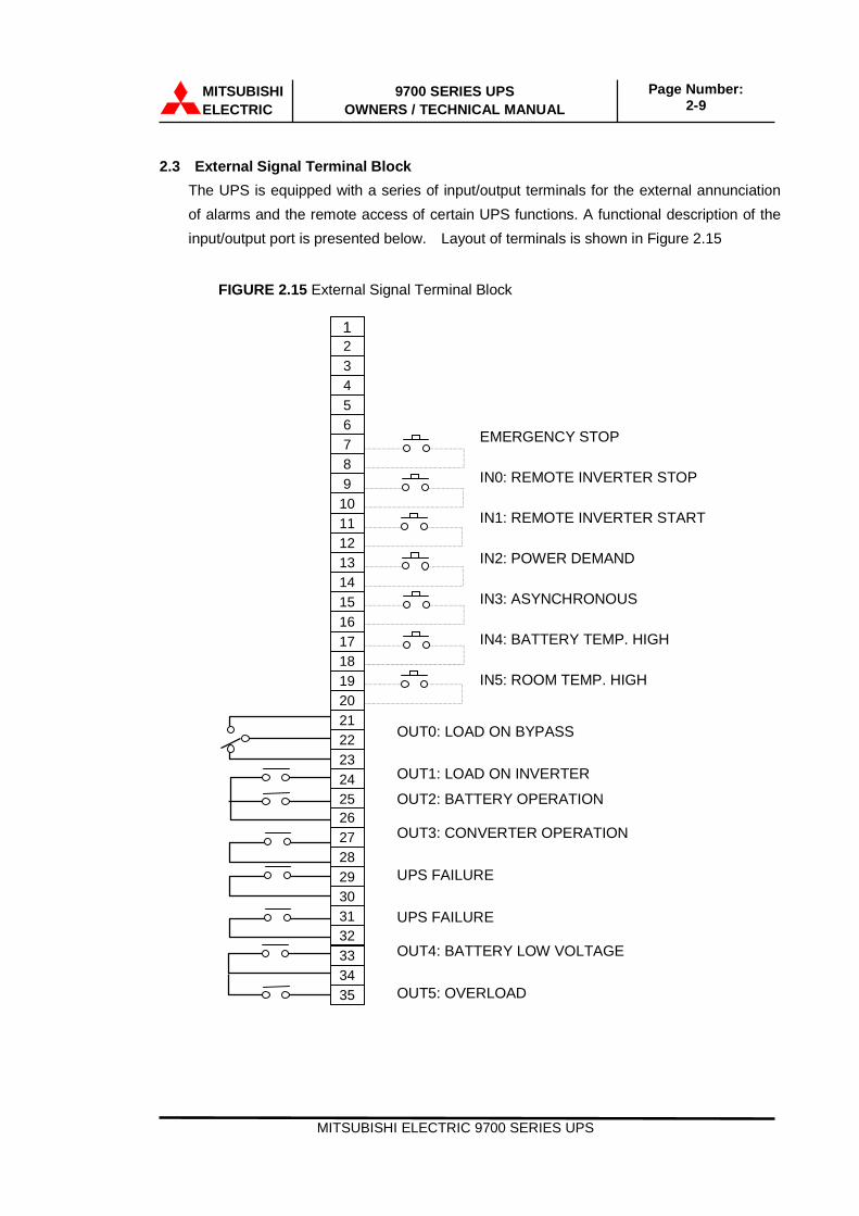
2.3 External Signal Terminal Block
The UPS is equipped with a series of input/output terminals for the external annunciation
of alarms and the remote access of certain UPS functions. A functional description of the
input/output port is presented below. Layout of terminals is shown in Figure 2.15
FIGURE 2.15 External Signal Terminal Block
EMERGENCY STOP
IN0: REMOTE INVERTER STOP
IN1: REMOTE INVERTER START
IN2: POWER DEMAND
IN3: ASYNCHRONOUS
IN4: BATTERY TEMP. HIGH
IN5: ROOM TEMP. HIGH
OUT0: LOAD ON BYPASS
OUT1: LOAD ON INVERTER
OUT2: BATTERY OPERATION
OUT3: CONVERTER OPERATION
UPS FAILURE
UPS FAILURE
OUT4: BATTERY LOW VOLTAGE
OUT5: OVERLOAD
10
12
3
4
5
6
7
8
9
11
12
13
14
15
16
17
18
19
20
21
22
23
24
25
26
27
28
29
30
31
32
33
34
35

MITSUBISHI
ELECTRIC
9700 SERIES UPS
OWNERS / TECHNICAL MANUAL
Page Number:2-10
MITSUBISHI ELECTRIC 9700 SERIES UPS
A) Output Contacts(for external alarm annunciation)
Output contacts consist of form “A” dry type contacts. Rated value of all output
contacts is 120Vac/0.5Aac or 30Vdc/1Adc. Operate all dry contacts at their rated
values or lower. Figure 2.16 illustrates typical installation. The external relay can
also be a lamp, LED, computer, etc.
FIGURE 2.16 Control Wiring for External Contacts
Terminal
UPS Cabinet External to UPSCabinet
Relay
Coil
PowerSource
RelayContact Terminal
Details of output alarm contacts :
Terminals 22 to 21 "Load on Bypass" contact (OUT0)
Activated when the power is supplied from the static bypass input.
Terminals 24 to 26 "Load on Inverter" contact (OUT1)
Activated when the power is supplied by the inverter.
Terminals 25 to 26 "Battery Operation" contact (OUT2)
Activated when the battery is operating following an AC power failure.
Terminals 27 to 28 “Converter Operation” contact (OUT3)
Activated when the converter is operating.
Terminals 29 to 30 "UPS failure" contact
Activated when a major fault has occurred to the system.
Terminals 31 to 32 "UPS failure" contact
Activated when a major fault has occurred to the system.
Terminals 34 to 33 "Battery Low Voltage" contact (OUT4)
Activated when DC voltage dropped below discharge end during inverter
operation.
Terminals 35 to 34 "Overload" contact (OUT5)
Activated when an overload has occurred to the system.
MITSUBISHI
ELECTRIC
9700 SERIES UPS
OWNERS / TECHNICAL MANUAL
Page Number:2-11
MITSUBISHI ELECTRIC 9700 SERIES UPS
NOTE: The UPS is equipped with a selectable output contact feature. The above
alarms are the default settings. Contact MITSUBISHI ELECTRIC
POWER PRODUCTS, INC. for set-up information.
B) Input Contacts(for remote access of UPS)
External contacts are provided by the user of the UPS system. Terminal voltage at
the UPS is 24Vdc. Provide external dry contact accordingly.
NOTE: Do not apply voltage to remote access input terminals. Damage to
UPS may result.
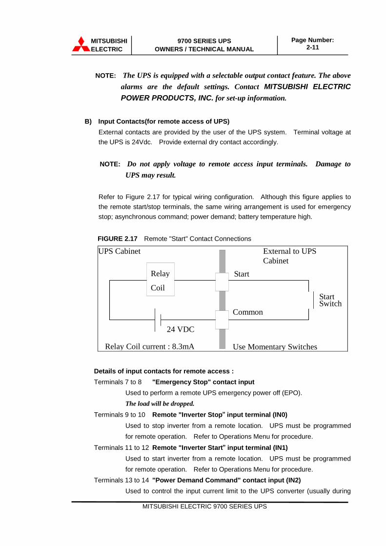
Refer to Figure 2.17 for typical wiring configuration. Although this figure applies to
the remote start/stop terminals, the same wiring arrangement is used for emergency
stop; asynchronous command; power demand; battery temperature high.
FIGURE 2.17 Remote "Start" Contact Connections
Start
Relay Coil current : 8.3mA Use Momentary Switches
UPS Cabinet External to UPSCabinet
Relay
Coil
24 VDC
StartSwitch
Common
Details of input contacts for remote access :
Terminals 7 to 8 "Emergency Stop" contact input
Used to perform a remote UPS emergency power off (EPO).
The load will be dropped.
Terminals 9 to 10 Remote "Inverter Stop” input terminal (IN0)
Used to stop inverter from a remote location. UPS must be programmed
for remote operation. Refer to Operations Menu for procedure.
Terminals 11 to 12 Remote "Inverter Start” input terminal (IN1)
Used to start inverter from a remote location. UPS must be programmed
for remote operation. Refer to Operations Menu for procedure.
Terminals 13 to 14 "Power Demand Command" contact input (IN2)
Used to control the input current limit to the UPS converter (usually during
MITSUBISHI
ELECTRIC
9700 SERIES UPS
OWNERS / TECHNICAL MANUAL
Page Number:2-12
MITSUBISHI ELECTRIC 9700 SERIES UPS
generator operation). Power demand is turned ON when the contact is
closed. Power demand is turned OFF when the contact is open.
Terminals 15 to 16 "Asynchronous Command" contact input (IN3)
Used to create an asynchronous condition between the static bypass source
and the inverter. Asynchronous condition is enabled when the switch is
closed. Asynchronous condition is disabled when the switch is opened.
Terminals 17 to 18 “BATTERY TEMP. HIGH” contact input (IN4)
Input fed by a thermocouple that monitors battery temperature. The
converter float voltage level is reduced for battery over-temperature
conditions. Use battery manufacture recommended thermocouple.
Terminals 19 to 20 “ROOM TEMP. HIGH” contact input (IN5)
Input fed by a thermocouple that monitors room temperature.
External thermocouple is user supplied.
NOTE : In all cases, a switch having a protective cover is recommended in order to
reduce possibility of accidental operation.
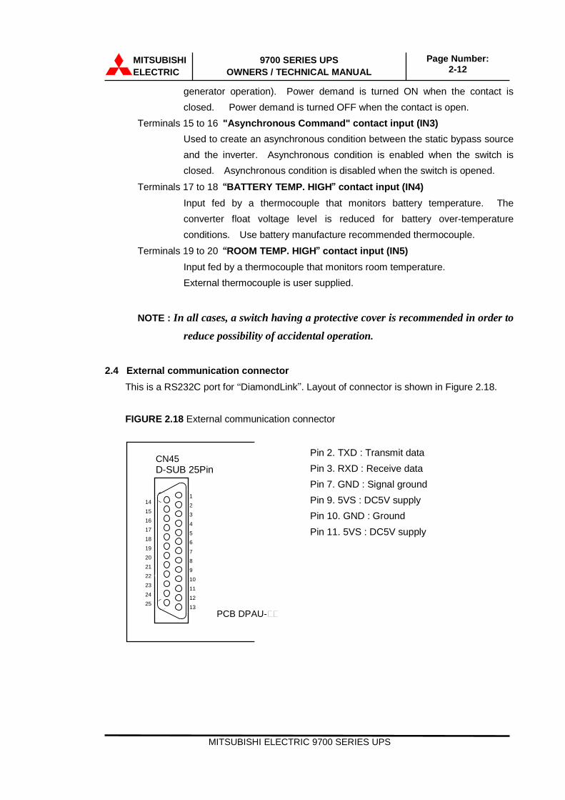
2.4 External communication connector
This is a RS232C port for “DiamondLink”. Layout of connector is shown in Figure 2.18.
FIGURE 2.18 External communication connector
Pin 2. TXD : Transmit data
Pin 3. RXD : Receive data
Pin 7. GND : Signal ground
Pin 9. 5VS : DC5V supply
Pin 10. GND : Ground
Pin 11. 5VS : DC5V supply
1
2
3
4
5
6
7
8
9
10
11
12
13
14
15
16
17
18
19
20
21
22
23
24
25
CN45D-SUB 25Pin
PCB DPAU-
MITSUBISHIELECTRIC
9700 SERIES UPSOWNERS / TECHNICAL MANUAL
Page Number:3-1
MITSUBISHI ELECTRIC 9700 SERIES UPS
3.0 INSTALLATION AND OPERATION
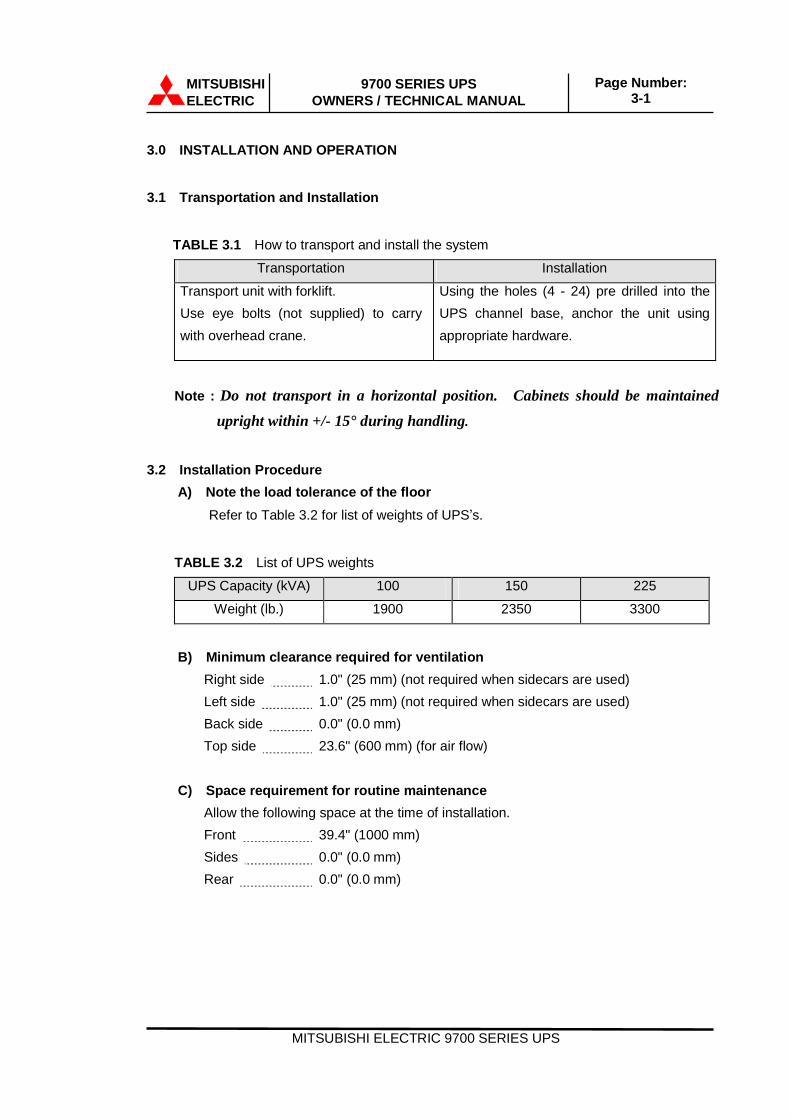
3.1 Transportation and Installation
TABLE 3.1 How to transport and install the system
Transportation Installation
Transport unit with forklift.
Use eye bolts (not supplied) to carry
with overhead crane.
Using the holes (4 - 24) pre drilled into the
UPS channel base, anchor the unit using
appropriate hardware.
Note : Do not transport in a horizontal position. Cabinets should be maintained
upright within +/- 15° during handling.
3.2 Installation Procedure
A) Note the load tolerance of the floor
Refer to Table 3.2 for list of weights of UPS’s.
TABLE 3.2 List of UPS weights
UPS Capacity (kVA) 100 150 225
Weight (lb.) 1900 2350 3300
B) Minimum clearance required for ventilation
Right side 1.0" (25 mm) (not required when sidecars are used)
Left side 1.0" (25 mm) (not required when sidecars are used)
Back side 0.0" (0.0 mm)
Top side 23.6" (600 mm) (for air flow)
C) Space requirement for routine maintenance
Allow the following space at the time of installation.
Front 39.4" (1000 mm)
Sides 0.0" (0.0 mm)
Rear 0.0" (0.0 mm)

MITSUBISHIELECTRIC
9700 SERIES UPSOWNERS / TECHNICAL MANUAL
Page Number:3-2
MITSUBISHI ELECTRIC 9700 SERIES UPS
D) External Battery Supply
Please refer to the following when installing batteries:
1. The customer shall make reference to the battery manufacturer's installation
manual for battery installation and maintenance instructions.
2. The maximum permitted fault current from the remote battery supply and the
DC voltage rating of the battery supply over-current protective device are
shown in Table 3.3.
TABLE 3.3 Maximum Permitted Fault Current
UPS CAPACITY
(kVA)
DC VOLTAGE
RATING (V)
MAXIMUM PERMITTED
FAULT CURRENT (A)
100 360 35000
150 360 25000
225 360 25000
3.3 Procedure for Cable Connections
A) Required metric tools – 19mm wrench, 19mm socket.
B) Confirm the capacity of the UPS being installed. Identify the input/output power
terminal blocks as shown in the appropriate Figure 3.1 through Figures 3.2-a~c.
C) Connect the internal control wire and power wire.
i) Control wire Inter-connect
DC breaker cabinet or battery cabinet
(1) CB2-UVR to terminal 5, 6 (100, 150, 225kVA) in bypass cabinet
section.
(2) CB2 Alarm to terminal 1, 2 (100, 150, 225kVA) in bypass cabinet
section.
(3) CB2 Auxiliary to terminal 3, 4 (100, 150, 225kVA) in bypass cabinet
section.
ii) Power wire Inter-connect
a) From user’s distribution cabinet
(1) X1 (A-phase) to A10 bus bar in UPS converter section.
(2) X2 (B-phase) to B10 bus bar in UPS converter section.
(3) X3 (C-phase) to C10 bus bar in UPS converter section.
b) DC Input to UPS
(1) Positive cable to BP bus bar in UPS converter section.
(2) Negative cable to NP bus bar in UPS converter section.
MITSUBISHIELECTRIC
9700 SERIES UPSOWNERS / TECHNICAL MANUAL
Page Number:3-3
MITSUBISHI ELECTRIC 9700 SERIES UPS
D) Connect the grounding conductor from the input service entrance to the UPS ground
bar.
E) Two (2) sources feeding the UPS:
i) Connect the converter input power cables from the input service entrance to the
converter input power terminals identified as A10, B10, C10 in Figures 3.2-a~c.
Input cables must be sized for an ampacity larger than the maximum input drawn
by the converter. Refer to Table 3.4 for recommended cable sizes.
ii) Confirm that an external bypass input circuit breaker (MCCB) is installed (refer to
WARNING 4). Connect the bypass input power cables from the input service
entrance to the bypass input power terminals identified as A40, B40, C40 and N60
in Figures 3.2-a~c. Bypass input cables must be sized for an ampacity larger
than the maximum output current capacity of the UPS. Refer to Table 3.4 for
recommended cable sizes.
F) One (1) source feeding the UPS:
i) Confirm that an external input circuit breaker sized to protect both the converter
input and the bypass lines is installed. Consult equipment nameplate for current
ratings. Connect the bypass input power cables from the input service entrance
to the bypass input power terminals identified as A40, B40, C40 and N60 in
Figures 3.2-a~c. Input cables must be sized for an ampacity larger than the
maximum current capacity of the UPS. Refer to Table 3.4 for recommended
cable sizes.
ii) Using adequately sized conductors per Table 3.4 and referring to the appropriate
figure identified in Figures 3.2-a~c, jumper bypass terminals A40, B40, C40 to
converter input power A10, B10, C10 identified Figures 3.2-a~c.
G) Referring to Figures 3.2-a~c, connect UPS load terminals A50, B50, C50 and N60 to
load distribution panel. Refer to Table 3.4 for cable sizes.
H) Connect external signal terminal block as needed. Refer to section 2.4 and Figure
2.15 for functional description. 12 AWG, or less, shielded conductor is
recommended.
MITSUBISHIELECTRIC
9700 SERIES UPSOWNERS / TECHNICAL MANUAL
Page Number:3-4
MITSUBISHI ELECTRIC 9700 SERIES UPS
NOTES: 1. Confirm that all UPS internal contactors(breakers) "CB1", "CB2", and
"CB3" are open before energizing UPS.
2. UPS power terminals are supplied with bus bar and hardware (12mm
diameter Nut/Bolt assembly). It is recommended that compression lugs be
used to fasten all input/output power cables. Refer to Table 3.5 for
recommended compression lugs and appropriate crimping tool.
3. If three wire source for input and bypass input is utilized, the neutral
conductor in the UPS must be banded to ground.
MITSUBISHIELECTRIC
9700 SERIES UPSOWNERS / TECHNICAL MANUAL
Page Number:3-5
MITSUBISHI ELECTRIC 9700 SERIES UPS
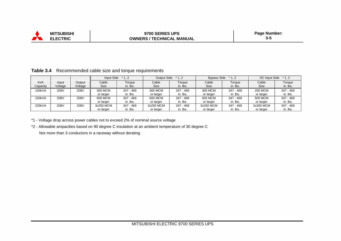
Table 3.4 Recommended cable size and torque requirements
Input Side * 1, 2 Output Side * 1, 2 Bypass Side * 1, 2 DC Input Side * 1, 2
kVACapacity
InputVoltage
OutputVoltage
CableSize
Torquein. lbs.
CableSize
Torquein. lbs.
CableSize
Torquein. lbs.
CableSize
Torquein. lbs.
100kVA 208V 208V 300 MCMor larger
347 - 469in. lbs.
300 MCMor larger
347 - 469in. lbs.
300 MCMor larger
347 - 469in. lbs.
250 MCMor larger
347 - 469in. lbs.
150kVA 208V 208V 600 MCMor larger
347 - 469in. lbs.
600 MCMor larger
347 - 469in. lbs.
600 MCMor larger
347 - 469in. lbs.
500 MCMor larger
347 - 469in. lbs.
225kVA 208V 208V 3x250 MCMor larger
347 - 469in. lbs.
3x250 MCMor larger
347 - 469in. lbs.
3x250 MCMor larger
347 - 469in. lbs.
2x300 MCMor larger
347 - 469in. lbs.
*1 - Voltage drop across power cables not to exceed 2% of nominal source voltage
*2 - Allowable ampacities based on 90 degree C insulation at an ambient temperature of 30 degree C
Not more than 3 conductors in a raceway without derating.
MITSUBISHIELECTRIC
9700 SERIES UPSOWNERS / TECHNICAL MANUAL
Page Number:3-6
MITSUBISHI ELECTRIC 9700 SERIES UPS
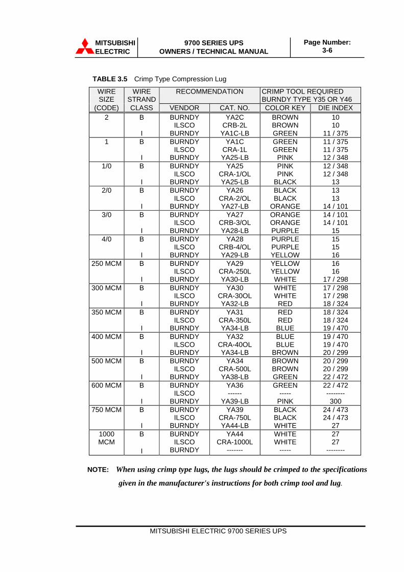
TABLE 3.5 Crimp Type Compression Lug
WIRESIZE
WIRESTRAND
RECOMMENDATION CRIMP TOOL REQUIREDBURNDY TYPE Y35 OR Y46
(CODE) CLASS VENDOR CAT. NO. COLOR KEY DIE INDEX
2 B
I
BURNDYILSCO
BURNDY
YA2CCRB-2L
YA1C-LB
BROWNBROWNGREEN
1010
11 / 3751 B
I
BURNDYILSCO
BURNDY
YA1CCRA-1LYA25-LB
GREENGREEN
PINK
11 / 37511 / 37512 / 348
1/0 B
I
BURNDYILSCO
BURNDY
YA25CRA-1/OLYA25-LB
PINKPINK
BLACK
12 / 34812 / 348
132/0 B
I
BURNDYILSCO
BURNDY
YA26CRA-2/OLYA27-LB
BLACKBLACK
ORANGE
1313
14 / 1013/0 B
I
BURNDYILSCO
BURNDY
YA27CRB-3/OLYA28-LB
ORANGEORANGEPURPLE
14 / 10114 / 101
154/0 B
I
BURNDYILSCO
BURNDY
YA28CRB-4/OLYA29-LB
PURPLEPURPLEYELLOW
151516
250 MCM B
I
BURNDYILSCO
BURNDY
YA29CRA-250LYA30-LB
YELLOWYELLOWWHITE
1616
17 / 298300 MCM B
I
BURNDYILSCO
BURNDY
YA30CRA-30OLYA32-LB
WHITEWHITERED
17 / 29817 / 29818 / 324
350 MCM B
I
BURNDYILSCO
BURNDY
YA31CRA-350LYA34-LB
REDREDBLUE
18 / 32418 / 32419 / 470
400 MCM B
I
BURNDYILSCO
BURNDY
YA32CRA-40OLYA34-LB
BLUEBLUE
BROWN
19 / 47019 / 47020 / 299
500 MCM B
I
BURNDYILSCO
BURNDY
YA34CRA-500LYA38-LB
BROWNBROWNGREEN
20 / 29920 / 29922 / 472
600 MCM B
I
BURNDYILSCO
BURNDY
YA36------
YA39-LB
GREEN-----
PINK
22 / 472--------300
750 MCM B
I
BURNDYILSCO
BURNDY
YA39CRA-750LYA44-LB
BLACKBLACKWHITE
24 / 47324 / 473
271000MCM
B
I
BURNDYILSCO
BURNDY
YA44CRA-1000L
-------
WHITEWHITE
-----
2727
--------
NOTE: When using crimp type lugs, the lugs should be crimped to the specifications
given in the manufacturer's instructions for both crimp tool and lug.

MITSUBISHIELECTRIC
9700 SERIES UPSOWNERS / TECHNICAL MANUAL
Page Number:3-7
MITSUBISHI ELECTRIC 9700 SERIES UPS
Fig.3.1 UPS Terminal Designation (100, 150, 225kVA)
Static TransferSwitch
AC BypassInput
OutputAC input
CB3
52S
52C
UPS ModuleBattery cabinet
CB1
CB2
Terminals:A40,B40,C40, N60
Terminals:A10,B10,C10
Terminals:BP, BN
Terminals:A50,B50,C50, N60
MITSUBISHI
ELECTRIC
9700 SERIES UPSOWNERS / TECHNICAL MANUAL
Page Number:3-8
MITSUBISHI ELECTRIC 9700 SERIES UPS
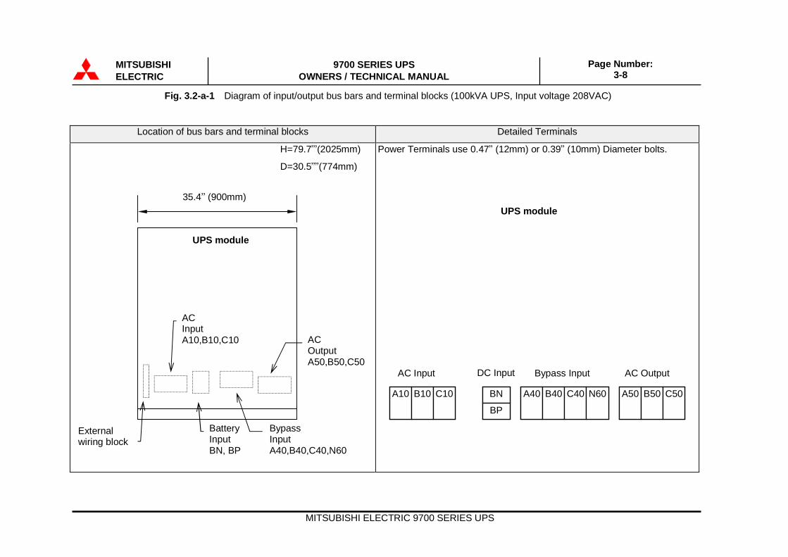
Fig. 3.2-a-1 Diagram of input/output bus bars and terminal blocks (100kVA UPS, Input voltage 208VAC)
Location of bus bars and terminal blocks Detailed Terminals
H=79.7”’(2025mm)
D=30.5””(774mm)
Power Terminals use 0.47” (12mm) or 0.39” (10mm) Diameter bolts.
35.4’’ (900mm)
BypassInputA40,B40,C40,N60
Externalwiring block
BatteryInputBN, BP
ACOutputA50,B50,C50
ACInputA10,B10,C10
UPS module
Bypass Input AC OutputAC Input DC Input
UPS module
A10 B10 C10 BN
BP
A40 B40 C40 N60 A50 B50 C50

MITSUBISHI
ELECTRIC
9700 SERIES UPSOWNERS / TECHNICAL MANUAL
Page Number:3-9
MITSUBISHI ELECTRIC 9700 SERIES UPS
Fig. 3.2-a-2 Diagram of Power Wire & Control Wire Inter-Connect (100kVA UPS, Input voltage 208VAC)
UPS module
BN
BP
UVR
Alarm
Auxiliary
DC circuit breaker
External signal terminal
PositiveNegative
Wall mounted DC breaker
6 5 4 3 2 1
MITSUBISHI
ELECTRIC
9700 SERIES UPSOWNERS / TECHNICAL MANUAL
Page Number:3-10
MITSUBISHI ELECTRIC 9700 SERIES UPS
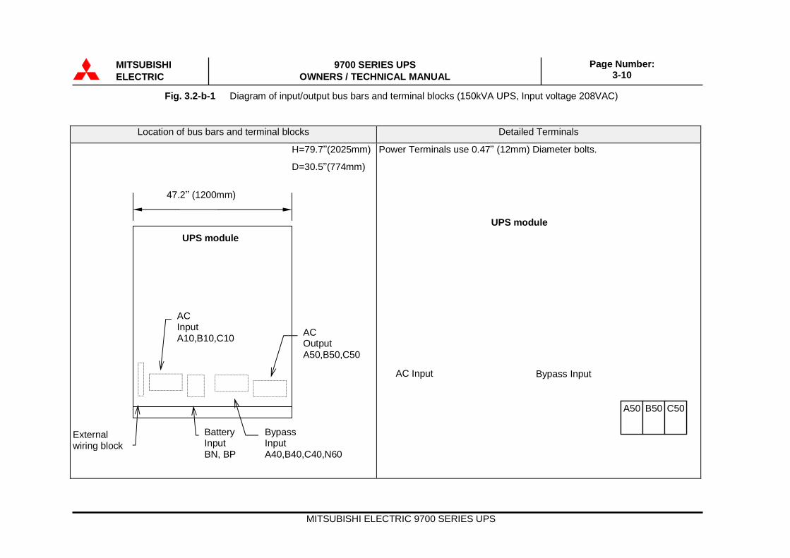
Fig. 3.2-b-1 Diagram of input/output bus bars and terminal blocks (150kVA UPS, Input voltage 208VAC)
Location of bus bars and terminal blocks Detailed Terminals
H=79.7’’(2025mm)
D=30.5”(774mm)
Power Terminals use 0.47” (12mm) Diameter bolts.
47.2’’ (1200mm)
Externalwiring block
BypassInputA40,B40,C40,N60
BatteryInputBN, BP
ACOutputA50,B50,C50
ACInputA10,B10,C10
UPS module
Bypass InputAC Input
UPS module
A50 B50 C50

MITSUBISHI
ELECTRIC
9700 SERIES UPSOWNERS / TECHNICAL MANUAL
Page Number:3-11
MITSUBISHI ELECTRIC 9700 SERIES UPS
Fig. 3.2-b-2 Diagram of Power Wire & Control Wire Inter-Connect (150kVA UPS, Input voltage 208VAC)
UPS module Wall mounted DC breaker
UVR
Alarm
Auxiliary
DC circuit breaker
External signal terminalPositiveNegative
BN
BP
6
5
4
3
2
1
MITSUBISHI
ELECTRIC
9700 SERIES UPSOWNERS / TECHNICAL MANUAL
Page Number:3-12
MITSUBISHI ELECTRIC 9700 SERIES UPS
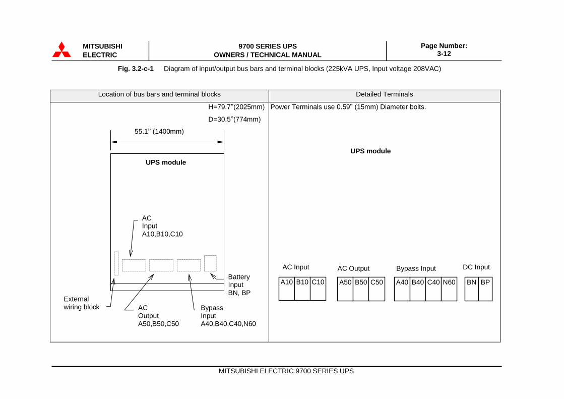
Fig. 3.2-c-1 Diagram of input/output bus bars and terminal blocks (225kVA UPS, Input voltage 208VAC)
Location of bus bars and terminal blocks Detailed Terminals
H=79.7’’(2025mm)
D=30.5”(774mm)
Power Terminals use 0.59” (15mm) Diameter bolts.
55.1’’ (1400mm)
Externalwiring block Bypass
InputA40,B40,C40,N60
BatteryInputBN, BP
ACOutputA50,B50,C50
ACInputA10,B10,C10
UPS module
Bypass InputAC Output
A10 B10 C10 BN BP
AC Input DC Input
A40 B40 C40 N60
UPS module
A50 B50 C50
MITSUBISHI
ELECTRIC
9700 SERIES UPSOWNERS / TECHNICAL MANUAL
Page Number:3-13
MITSUBISHI ELECTRIC 9700 SERIES UPS
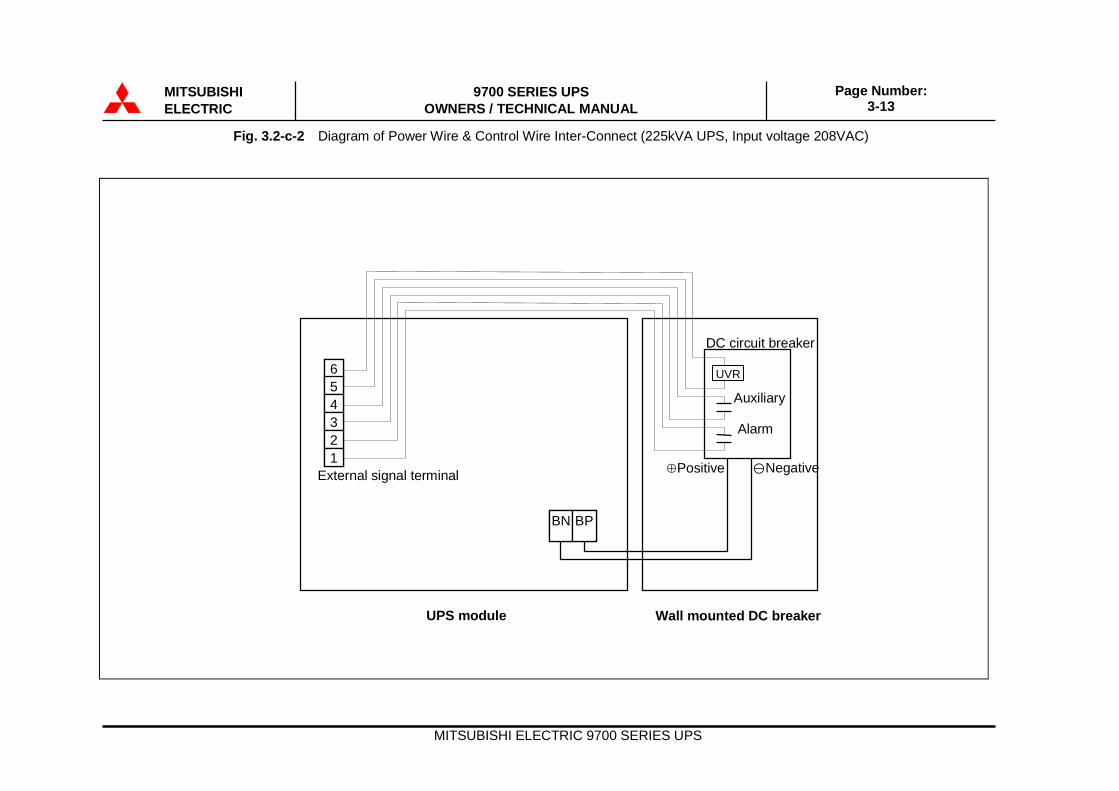
Fig. 3.2-c-2 Diagram of Power Wire & Control Wire Inter-Connect (225kVA UPS, Input voltage 208VAC)
UPS module Wall mounted DC breaker
UVR
Alarm
Auxiliary
DC circuit breaker
External signal terminalPositive Negative
6
5
4
3
2
1
BN BP

MITSUBISHIELECTRIC
9700 SERIES UPSOWNERS / TECHNICAL MANUAL
Page Number:3-14
MITSUBISHI ELECTRIC 9700 SERIES UPS
3.4 0perating Procedures
A) UPS Start-up Procedure
1. Verify that the External Bypass input Circuit Breaker (user supplied. Refer to warning
4) is closed.
2. Close Control Circuit Breaker (CB103).
3. Close Control Circuit Breaker (CB101).
4. After a few seconds, an audible annunciator will sound and the AC Input Circuit
Contactor (CB1) will automatically close.
5. The audible annunciator will sound and the instruction “RESET CB2” will be displayed
on the Liquid Crystal Display (LCD) panel.
6. Reset the Battery Disconnect Circuit Breaker (CB2). To reset CB2, press the handle
down until the handle stays in the off position.
7. Close the Battery Disconnect Circuit Breaker (CB2).
8. The audible annunciator will sound and the instruction "PRESS START / STOP KEY"
will be displayed on the LCD panel. ( Figure 3.3)
9. Press the "Start" key in the inverter START/STOP menu on the LCD panel. (Figure
3.4)
FIGURE 3.3 START-UP MENU FIGURE 3.4 INVERTER START/STOP
10. When the message "LOCAL" is displayed on the LCD panel, the inverter start
operation can only be performed locally at the UPS front panel. When the message
"REMOTE" is displayed on the LCD pane, the inverter start operation can be started
by remote operation only. Lock-out of one inverter start mode is inherent and cannot
be.
11. If a local inverter start operation is required (at the UPS), select "Local" in
"Remote/Local" function via the Operation menu. Select “LOCAL” mode.
12. Within five (5) seconds, the Inverter will start-up and begin supplying power to the
critical load.
13. If power is not supplied to the load, follow the instructions on the LCD panel.
MITSUBISHIELECTRIC
9700 SERIES UPSOWNERS / TECHNICAL MANUAL
Page Number:3-15
MITSUBISHI ELECTRIC 9700 SERIES UPS
B) UPS Shutdown Procedure
1. If a total UPS shutdown is required, verify that the critical load is OFF.
2. Select "STOP MENU" from the Operations menu.
3. Press the "INVERTER STOP" key in the START/STOP menu on the LCD panel.
The UPS will transfer the load to the static bypass line.
4. When the "LOCAL" is displayed on the LCD panel, the operation can be performed at
the UPS front panel. When the "REMOTE is displayed on the LCD pane, the
Inverter can be stopped by remote operation only. If the inverter stop operation is
required locally (at the UPS), select to "LOCAL" from the "Remote/Local" selection
in the Operations menu. Select “Local” mode.
5. Generally, the Inverter alone will be stopped and the Converter will remain energized
to float-charge the batteries.
6. If stopping the Converter is required, The operation instruction “TURN OFF CB2” will
be displayed on the LCD panel.
7. Open the Battery Disconnect circuit breaker (CB2) manually. The operation
instruction “TURN OFF CB101” will be displayed on the LCD panel.
WARNING : Verify the load is OFF if the next step is to be performed.
8. Open the control circuit breaker (CB101).
9. Open the AC Input circuit contactor (CB1) automatically.
NOTE : Power to the critical load is supplied through the static bypass line. Power
to the critical will be lost after execution of the next step. The load will drop.
10. If turning off all power to critical load is desired, open the control circuit breaker
(CB103), then open the Bypass input Circuit Breaker(MCCB inside the user’s cabinet)
manually.
11. Contactor CB3 will open automatically.
CAUTION : All UPS power terminals are still live. Lethal voltages present.
De-energize all external sources of AC and DC voltages before handling UPS.

MITSUBISHIELECTRIC
9700 SERIES UPSOWNERS / TECHNICAL MANUAL
Page Number:4-1
MITSUBISHI ELECTRIC 9700 SERIES UPS
4.0 RESPONSE TO UPS FAILURE
Depress Silence Alarm Key on MAIN menu.
Refer to the list of fault codes for the description of the
error.
Take necessary action per the guidance on the display.
When faults occur continuously contact the Authorized
Mitsubishi Service Representative or call Mitsubishi at
1-800-887-7830.
Note
The error code indicated on the LCD display panel at the time of UPS alarm
condition is very important. In order to reduce repair time, please include this
information, along with the operation status and load status, on all
correspondence with Mitsubishi’s field service group.
UPS FAULT
Annunciator Silence
Recording of Fault
Primary Action
Information to Service Center
MITSUBISHI
ELECTRIC
9700 SERIES UPS
OWNERS / TECHNICAL MANUAL
Page Number:5-1
MITSUBISHI ELECTRIC 9700 SERIES UPS
5.0 PARTS REPLACEMENT
Contact Mitsubishi or its Authorized Service Center on all issues regarding the
replacement of parts.
A) Battery
Battery lifetime may vary according to the frequency of use and the average ambient
operating temperature. Battery end of life is defined as the state of charge resulting
in an ampere-hour capacity less than, or equal to, 80% of nominal capacity. Replace
battery if capacity is within this percentage.
B) UPS Component Parts
Contact Mitsubishi or its Authorized Service Center for a complete parts replacement
schedule. Recommended replacement time interval varies with operating
environment. Contact Mitsubishi or its Authorized Service Center for application
specific recommendations.
MITSUBISHI
ELECTRIC
9700 SERIES UPS
OWNERS / TECHNICAL MANUAL
Page Number:6-1
MITSUBISHI ELECTRIC 9700 SERIES UPS
6.0 FAULT CODES
This section covers the fault codes, their description and required action.
At time of error :
A) Verify and record the occurrence of the alarm. Note details of alarm message on
the LCD display panel.
Contact Mitsubishi Electric Power Products, Inc. at 1-800-887-7830.
B) If a circuit breaker (MCCB) is in the trip state, depress the toggle to reset the
breaker before closing it again.
MITSUBISHIELECTRIC
9700 SERIES UPSOWNERS / TECHNICAL MANUAL
Page Number:6-2
MITSUBISHI ELECTRIC 9700 SERIES UPS
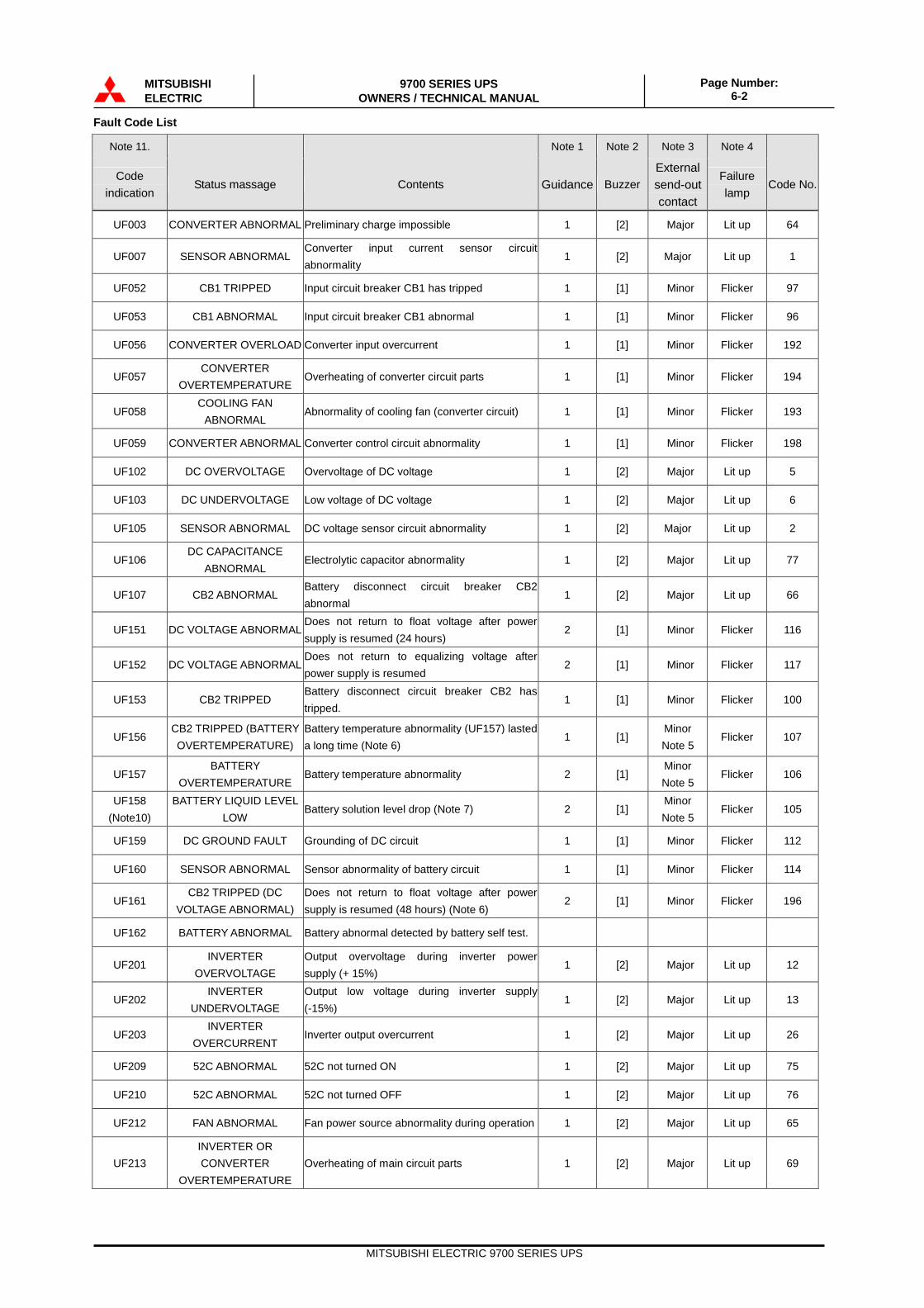
Fault Code List
Note 11. Note 1 Note 2 Note 3 Note 4
Code
indicationStatus massage Contents Guidance Buzzer
External
send-out
contact
Failure
lampCode No.
UF003 CONVERTER ABNORMAL Preliminary charge impossible 1 [2] Major Lit up 64
UF007 SENSOR ABNORMALConverter input current sensor circuit
abnormality1 [2] Major Lit up 1
UF052 CB1 TRIPPED Input circuit breaker CB1 has tripped 1 [1] Minor Flicker 97
UF053 CB1 ABNORMAL Input circuit breaker CB1 abnormal 1 [1] Minor Flicker 96
UF056 CONVERTER OVERLOAD Converter input overcurrent 1 [1] Minor Flicker 192
UF057CONVERTER
OVERTEMPERATUREOverheating of converter circuit parts 1 [1] Minor Flicker 194
UF058COOLING FAN
ABNORMALAbnormality of cooling fan (converter circuit) 1 [1] Minor Flicker 193
UF059 CONVERTER ABNORMAL Converter control circuit abnormality 1 [1] Minor Flicker 198
UF102 DC OVERVOLTAGE Overvoltage of DC voltage 1 [2] Major Lit up 5
UF103 DC UNDERVOLTAGE Low voltage of DC voltage 1 [2] Major Lit up 6
UF105 SENSOR ABNORMAL DC voltage sensor circuit abnormality 1 [2] Major Lit up 2
UF106DC CAPACITANCE
ABNORMALElectrolytic capacitor abnormality 1 [2] Major Lit up 77
UF107 CB2 ABNORMALBattery disconnect circuit breaker CB2
abnormal1 [2] Major Lit up 66
UF151 DC VOLTAGE ABNORMALDoes not return to float voltage after power
supply is resumed (24 hours)2 [1] Minor Flicker 116
UF152 DC VOLTAGE ABNORMALDoes not return to equalizing voltage after
power supply is resumed2 [1] Minor Flicker 117
UF153 CB2 TRIPPEDBattery disconnect circuit breaker CB2 has
tripped.1 [1] Minor Flicker 100
UF156CB2 TRIPPED (BATTERY
OVERTEMPERATURE)
Battery temperature abnormality (UF157) lasted
a long time (Note 6)1 [1]
Minor
Note 5Flicker 107
UF157BATTERY
OVERTEMPERATUREBattery temperature abnormality 2 [1]
Minor
Note 5Flicker 106
UF158
(Note10)
BATTERY LIQUID LEVEL
LOWBattery solution level drop (Note 7) 2 [1]
Minor
Note 5Flicker 105
UF159 DC GROUND FAULT Grounding of DC circuit 1 [1] Minor Flicker 112
UF160 SENSOR ABNORMAL Sensor abnormality of battery circuit 1 [1] Minor Flicker 114
UF161CB2 TRIPPED (DC
VOLTAGE ABNORMAL)
Does not return to float voltage after power
supply is resumed (48 hours) (Note 6)2 [1] Minor Flicker 196
UF162 BATTERY ABNORMAL Battery abnormal detected by battery self test.
UF201INVERTER
OVERVOLTAGE
Output overvoltage during inverter power
supply (+ 15%)1 [2] Major Lit up 12
UF202INVERTER
UNDERVOLTAGE
Output low voltage during inverter supply
(-15%)1 [2] Major Lit up 13
UF203INVERTER
OVERCURRENTInverter output overcurrent 1 [2] Major Lit up 26
UF209 52C ABNORMAL 52C not turned ON 1 [2] Major Lit up 75
UF210 52C ABNORMAL 52C not turned OFF 1 [2] Major Lit up 76
UF212 FAN ABNORMAL Fan power source abnormality during operation 1 [2] Major Lit up 65
UF213
INVERTER OR
CONVERTER
OVERTEMPERATURE
Overheating of main circuit parts 1 [2] Major Lit up 69
MITSUBISHIELECTRIC
9700 SERIES UPSOWNERS / TECHNICAL MANUAL
Page Number:6-3
MITSUBISHI ELECTRIC 9700 SERIES UPS
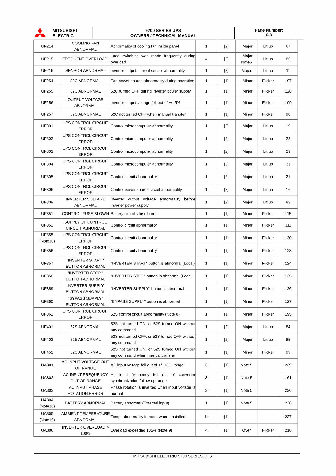
UF214COOLING FAN
ABNORMALAbnormality of cooling fan inside panel 1 [2] Major Lit up 67
UF215 FREQUENT OVERLOAD!Load switching was made frequently during
overload4 [2]
Major
Note5Lit up 86
UF216 SENSOR ABNORMAL Inverter output current sensor abnormality 1 [2] Major Lit up 11
UF254 88C ABNORMAL Fan power source abnormality during operation 1 [1] Minor Flicker 197
UF255 52C ABNORMAL 52C turned OFF during inverter power supply 1 [1] Minor Flicker 128
UF256OUTPUT VOLTAGE
ABNORMALInverter output voltage fell out of +/- 5% 1 [1] Minor Flicker 109
UF257 52C ABNORMAL 52C not turned OFF when manual transfer 1 [1] Minor Flicker 98
UF301UPS CONTROL CIRCUIT
ERRORControl microcomputer abnormality 1 [2] Major Lit up 19
UF302UPS CONTROL CIRCUIT
ERRORControl microcomputer abnormality 1 [2] Major Lit up 28
UF303UPS CONTROL CIRCUIT
ERRORControl microcomputer abnormality 1 [2] Major Lit up 29
UF304UPS CONTROL CIRCUIT
ERRORControl microcomputer abnormality 1 [2] Major Lit up 31
UF305UPS CONTROL CIRCUIT
ERRORControl circuit abnormality 1 [2] Major Lit up 21
UF306UPS CONTROL CIRCUIT
ERRORControl power source circuit abnormality 1 [2] Major Lit up 16
UF309INVERTER VOLTAGE
ABNORMAL
Inverter output voltage abnormality before
inverter power supply1 [2] Major Lit up 83
UF351 CONTROL FUSE BLOWN Battery circuit's fuse burnt 1 [1] Minor Flicker 115
UF352SUPPLY OF CONTROL
CIRCUIT ABNORMALControl circuit abnormality 1 [1] Minor Flicker 111
UF355
(Note10)
UPS CONTROL CIRCUIT
ERRORControl circuit abnormality 1 [1] Minor Flicker 130
UF356UPS CONTROL CIRCUIT
ERRORControl circuit abnormality 1 [1] Minor Flicker 123
UF357"INVERTER START "
BUTTON ABNORMAL"INVERTER START" button is abnormal (Local) 1 [1] Minor Flicker 124
UF358"INVERTER STOP "
BUTTON ABNORMAL"INVERTER STOP" button is abnormal (Local) 1 [1] Minor Flicker 125
UF359"INVERTER SUPPLY"
BUTTON ABNORMAL"INVERTER SUPPLY" button is abnormal 1 [1] Minor Flicker 126
UF360"BYPASS SUPPLY"
BUTTON ABNORMAL"BYPASS SUPPLY" button is abnormal 1 [1] Minor Flicker 127
UF362UPS CONTROL CIRCUIT
ERROR52S control circuit abnormality (Note 8) 1 [1] Minor Flicker 195
UF401 52S ABNORMAL52S not turned ON, or 52S turned ON without
any command1 [2] Major Lit up 84
UF402 52S ABNORMAL52S not turned OFF, or 52S turned OFF without
any command1 [2] Major Lit up 85
UF451 52S ABNORMAL52S not turned ON, or 52S turned ON without
any command when manual transfer1 [1] Minor Flicker 99
UA801AC INPUT VOLTAGE OUT
OF RANGEAC input voltage fell out of +/- 18% range 3 [1] Note 5 239
UA802AC INPUT FREQUENCY
OUT OF RANGE
Ac input frequency fell out of converter
synchronization follow-up range3 [1] Note 5 161
UA803AC INPUT PHASE
ROTATION ERROR
Phase rotation is inverted when input voltage is
normal3 [1] Note 5 236
UA804
(Note10)BATTERY ABNORMAL Battery abnormal (External input) 1 [1] Note 5 238
UA805
(Note10)
AMBIENT TEMPERATURE
ABNORMALTemp. abnormality in room where installed 11 [1] 237
UA806INVERTER OVERLOAD >
100%Overload exceeded 105% (Note 9) 4 [1] Over Flicker 216
MITSUBISHIELECTRIC
9700 SERIES UPSOWNERS / TECHNICAL MANUAL
Page Number:6-4
MITSUBISHI ELECTRIC 9700 SERIES UPS
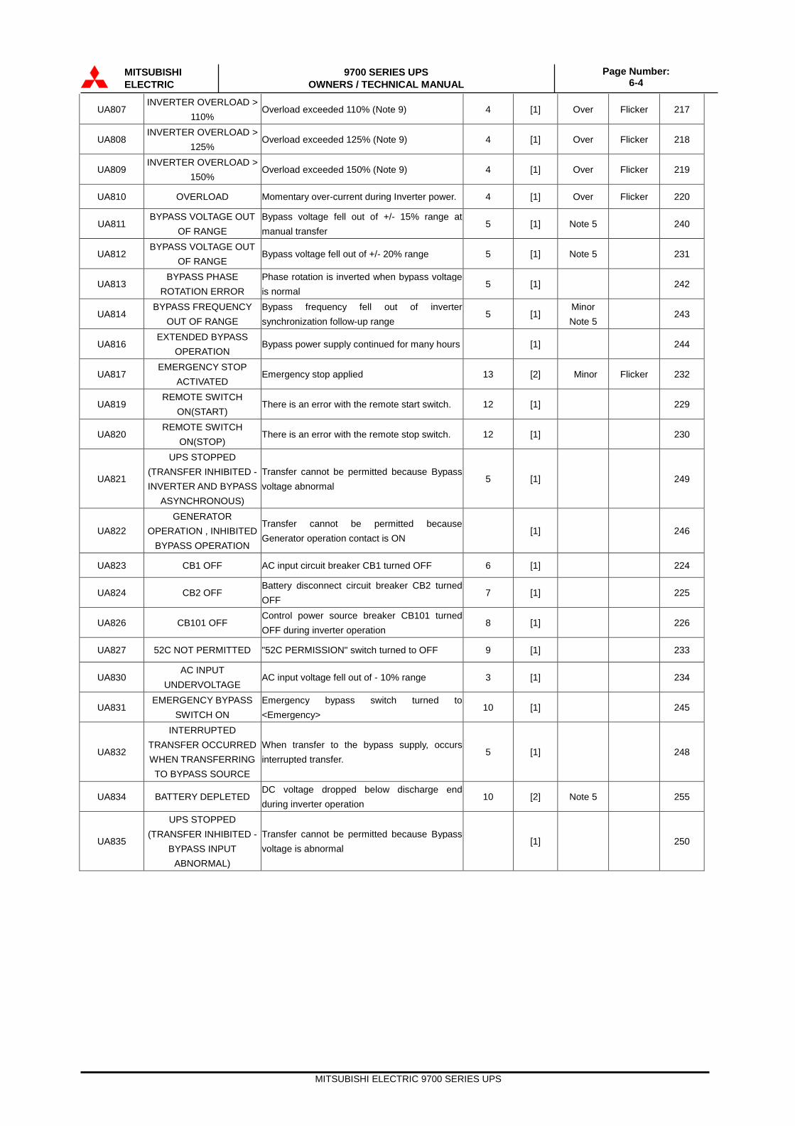
UA807INVERTER OVERLOAD >
110%Overload exceeded 110% (Note 9) 4 [1] Over Flicker 217
UA808INVERTER OVERLOAD >
125%Overload exceeded 125% (Note 9) 4 [1] Over Flicker 218
UA809INVERTER OVERLOAD >
150%Overload exceeded 150% (Note 9) 4 [1] Over Flicker 219
UA810 OVERLOAD Momentary over-current during Inverter power. 4 [1] Over Flicker 220
UA811BYPASS VOLTAGE OUT
OF RANGE
Bypass voltage fell out of +/- 15% range at
manual transfer5 [1] Note 5 240
UA812BYPASS VOLTAGE OUT
OF RANGEBypass voltage fell out of +/- 20% range 5 [1] Note 5 231
UA813BYPASS PHASE
ROTATION ERROR
Phase rotation is inverted when bypass voltage
is normal5 [1] 242
UA814BYPASS FREQUENCY
OUT OF RANGE
Bypass frequency fell out of inverter
synchronization follow-up range5 [1]
Minor
Note 5243
UA816EXTENDED BYPASS
OPERATIONBypass power supply continued for many hours [1] 244
UA817EMERGENCY STOP
ACTIVATEDEmergency stop applied 13 [2] Minor Flicker 232
UA819REMOTE SWITCH
ON(START)There is an error with the remote start switch. 12 [1] 229
UA820REMOTE SWITCH
ON(STOP)There is an error with the remote stop switch. 12 [1] 230
UA821
UPS STOPPED
(TRANSFER INHIBITED -
INVERTER AND BYPASS
ASYNCHRONOUS)
Transfer cannot be permitted because Bypass
voltage abnormal5 [1] 249
UA822
GENERATOR
OPERATION , INHIBITED
BYPASS OPERATION
Transfer cannot be permitted because
Generator operation contact is ON[1] 246
UA823 CB1 OFF AC input circuit breaker CB1 turned OFF 6 [1] 224
UA824 CB2 OFFBattery disconnect circuit breaker CB2 turned
OFF7 [1] 225
UA826 CB101 OFFControl power source breaker CB101 turned
OFF during inverter operation8 [1] 226
UA827 52C NOT PERMITTED "52C PERMISSION" switch turned to OFF 9 [1] 233
UA830AC INPUT
UNDERVOLTAGEAC input voltage fell out of - 10% range 3 [1] 234
UA831EMERGENCY BYPASS
SWITCH ON
Emergency bypass switch turned to
<Emergency>10 [1] 245
UA832
INTERRUPTED
TRANSFER OCCURRED
WHEN TRANSFERRING
TO BYPASS SOURCE
When transfer to the bypass supply, occurs
interrupted transfer.5 [1] 248
UA834 BATTERY DEPLETEDDC voltage dropped below discharge end
during inverter operation10 [2] Note 5 255
UA835
UPS STOPPED
(TRANSFER INHIBITED -
BYPASS INPUT
ABNORMAL)
Transfer cannot be permitted because Bypass
voltage is abnormal[1] 250
MITSUBISHI
ELECTRIC
9700 SERIES UPS
OWNERS / TECHNICAL MANUAL
Page Number:6-5
MITSUBISHI ELECTRIC 9700 SERIES UPS
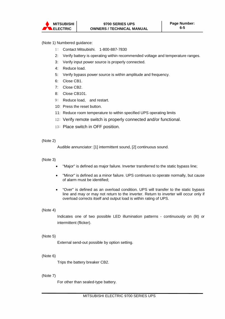
(Note 1) Numbered guidance:
1: Contact Mitsubishi. 1-800-887-7830
2: Verify battery is operating within recommended voltage and temperature ranges.
3: Verify input power source is properly connected.
4: Reduce load.
5: Verify bypass power source is within amplitude and frequency.
6: Close CB1.
7: Close CB2.
8: Close CB101.
9: Reduce load, and restart.
10: Press the reset button.
11: Reduce room temperature to within specified UPS operating limits
12: Verify remote switch is properly connected and/or functional.
13: Place switch in OFF position.
(Note 2)
Audible annunciator: [1] intermittent sound, [2] continuous sound.
(Note 3)
"Major" is defined as major failure. Inverter transferred to the static bypass line;
"Minor" is defined as a minor failure. UPS continues to operate normally, but causeof alarm must be identified;
“Over" is defined as an overload condition. UPS will transfer to the static bypassline and may or may not return to the inverter. Return to inverter will occur only ifoverload corrects itself and output load is within rating of UPS.
(Note 4)
Indicates one of two possible LED illumination patterns - continuously on (lit) or
intermittent (flicker).
(Note 5)
External send-out possible by option setting.
(Note 6)
Trips the battery breaker CB2.
(Note 7)
For other than sealed-type battery.
MITSUBISHI
ELECTRIC
9700 SERIES UPS
OWNERS / TECHNICAL MANUAL
Page Number:6-6
MITSUBISHI ELECTRIC 9700 SERIES UPS
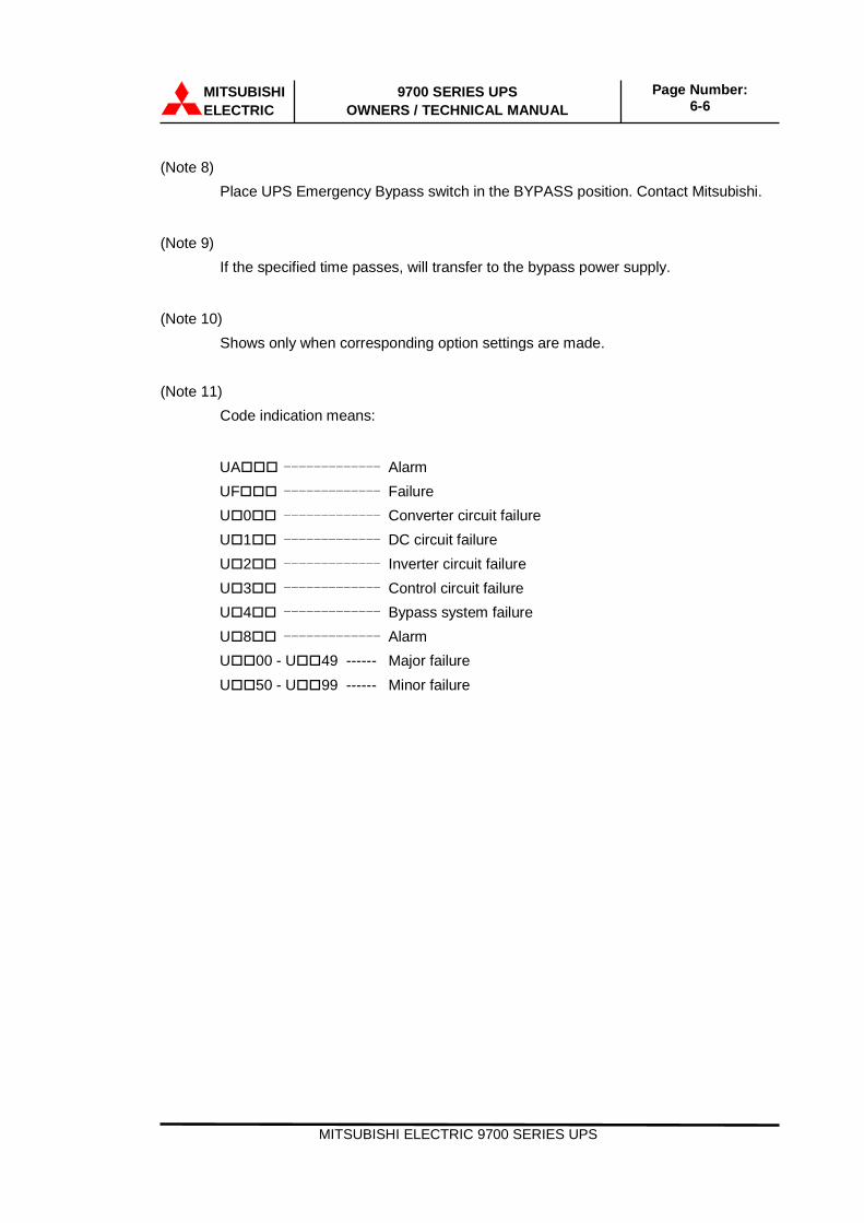
(Note 8)
Place UPS Emergency Bypass switch in the BYPASS position. Contact Mitsubishi.
(Note 9)
If the specified time passes, will transfer to the bypass power supply.
(Note 10)
Shows only when corresponding option settings are made.
(Note 11)
Code indication means:
UA ------------- Alarm
UF ------------- Failure
U0 ------------- Converter circuit failure
U1 ------------- DC circuit failure
U2 ------------- Inverter circuit failure
U3 ------------- Control circuit failure
U4 ------------- Bypass system failure
U8 ------------- Alarm
U00 - U49 ------ Major failure
U50 - U99 ------ Minor failure
MITSUBISHI ELECTRIC 9700 SERIES UPS
MITSUBISHI
ELECTRIC
9700 SERIES UPS
OWNERS / TECHNICAL MANUAL
Page Number:7-1
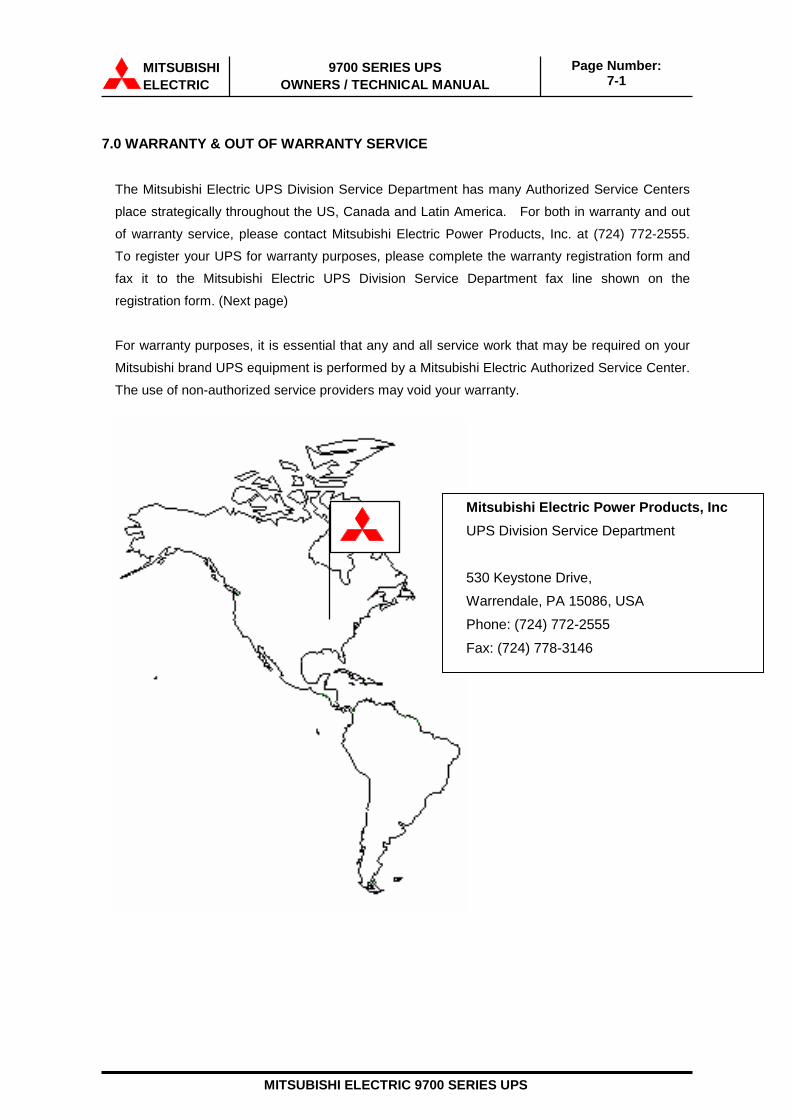
7.0 WARRANTY & OUT OF WARRANTY SERVICE
The Mitsubishi Electric UPS Division Service Department has many Authorized Service Centers
place strategically throughout the US, Canada and Latin America. For both in warranty and out
of warranty service, please contact Mitsubishi Electric Power Products, Inc. at (724) 772-2555.
To register your UPS for warranty purposes, please complete the warranty registration form and
fax it to the Mitsubishi Electric UPS Division Service Department fax line shown on the
registration form. (Next page)
For warranty purposes, it is essential that any and all service work that may be required on your
Mitsubishi brand UPS equipment is performed by a Mitsubishi Electric Authorized Service Center.
The use of non-authorized service providers may void your warranty.
Mitsubishi Electric Power Products, Inc
UPS Division Service Department
530 Keystone Drive,
Warrendale, PA 15086, USA
Phone: (724) 772-2555
Fax: (724) 778-3146
MITSUBISHI ELECTRIC 9700 SERIES UPS
MITSUBISHI
ELECTRIC
9700 SERIES UPS
OWNERS / TECHNICAL MANUAL
Page Number:7-2
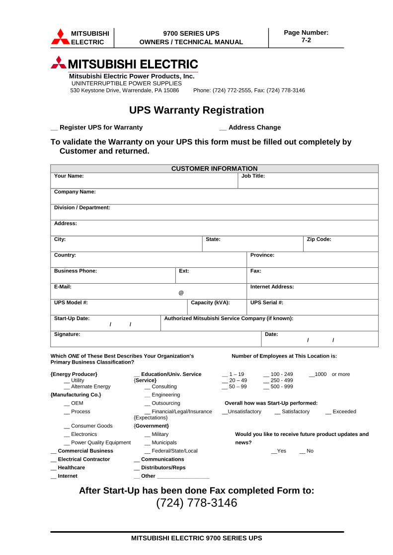
Mitsubishi Electric Power Products, Inc.UNINTERRUPTIBLE POWER SUPPLIES530 Keystone Drive, Warrendale, PA 15086 Phone: (724) 772-2555, Fax: (724) 778-3146
UPS Warranty Registration
__ Register UPS for Warranty __ Address Change
To validate the Warranty on your UPS this form must be filled out completely byCustomer and returned.
CUSTOMER INFORMATIONYour Name: Job Title:
Company Name:
Division / Department:
Address:
City: State: Zip Code:
Country: Province:
Business Phone: Ext: Fax:
E-Mail:@
Internet Address:
UPS Model #: Capacity (kVA): UPS Serial #:
Start-Up Date:/ /
Authorized Mitsubishi Service Company (if known):
Signature: Date:/ /
Which ONE of These Best Describes Your Organization’s Number of Employees at This Location is:Primary Business Classification?
{Energy Producer} __ Education/Univ. Service __ 1 – 19 __ 100 - 249 __1000 or more__ Utility {Service} __ 20 – 49 __ 250 - 499__ Alternate Energy __ Consulting __ 50 – 99 __ 500 - 999
{Manufacturing Co.} __ Engineering
__ OEM __ Outsourcing Overall how was Start-Up performed:
__ Process __ Financial/Legal/Insurance __Unsatisfactory __ Satisfactory __ Exceeded{Expectations}
__ Consumer Goods {Government}
__ Electronics __ Military Would you like to receive future product updates and
__ Power Quality Equipment __ Municipals news?
__ Commercial Business __ Federal/State/Local __Yes __ No
__ Electrical Contractor __ Communications
__ Healthcare __ Distributors/Reps
__ Internet __ Other __________________
After Start-Up has been done Fax completed Form to:
(724) 778-3146